1
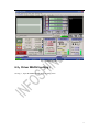
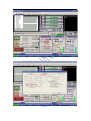
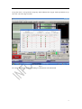
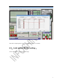
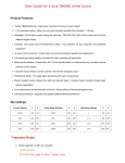
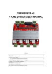
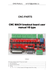
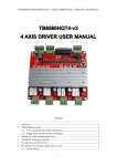
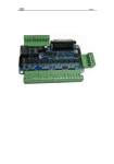
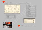
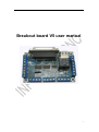
Breakout board V5 user manual
1
1、Instruction:
It can most connection 5pcs driver and control 5pcs motor in the same time
It is with 4-wire limit switch to insure our safty movement
It is with relay port to contro the cnc spindle
Working voltage is 5VDC and support with MACH3,EMC2,KCAM4 software
2、Breakout board view:
2
3、 The connection between breakout
board and driver:
4、Limit switch port connection:
3
5、DB25 parallel port definition
Fig 5.1
Parallel port output PIN definition:
PIN1
PIN2
PIN3
PIN4
PIN5
PIN6
PIN7
PIN8
PIN9
PIN10
STEPE
STEPA
DIRA
STEPB
DIRB
STEPC
DIRC
STEPD
DIRD
DIN1
B axis
PU
X axis
PU
X axis Y axis
DIR
PU
Y axis
DIR
Z axis
PU
Z axis
DIR
A axis
PU
A axis
DIR
Limit 1
PIN11
PIN12
PIN13
PIN14
PIN17
PIN16
PIN18~25
DIN2
DIN3
DIN4
DIRE
EN
RLY
GND
Limit 2
Limit 3
Limit 4
B axis
DIR
All
axis
enable
Relay
GND
4
6、Mach3 software setting:
6.1MACH open:
Fig 1
Open MACH3 software,select mach3MILL then click OK
5
Fig 2 MACH3 interface
6.2、Driver MACH3 setting:
See Fig 3,Open the PORT &PINS menu of config menu
6
Fig 3
Fig 4
7
Set up the circle 1 of Fig4 for the frequency which influence the stepper motor speed,then set up
the circle 2 as below Fig 5 for PIN
Fig 5
Pls setting the software as above according to our definition of breakout PIN
8
Fig 6
The select “output signals” as Fig 6, set up the pin numer as 16 and 17.
6.3、Limit switch MACH3 setting:
Click “input signal” to setting as below Fig 7
9
Fig 7
6.4、Run of the G code:
See Fig 8,open the G code menu
10
Fig 8
Find your G code,then open as Fig 9:
Fig 9
11
Fig 10
You will see “RESET” flicker after open the G code,you can click it to stop flicker,then run the
circle2 “CYCLESTART”
in addition if you need manual control,you can press the TAB of keyboard,the manual control
interface as below Fig 11
12
Fig 11
13