1
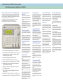
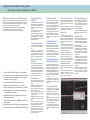
Technical Specifications
Technical Specifications continued
GENERAL
WAVEFORMS
Standard Waveforms
Sine, square, triangle, DC, positive ramp, negative ramp, sin(x)/x, pulse, pulse train,
cosine, haversine and havercosine.
Frequency Accuracy: Better than 10 ppm for 1 year.
o
Temperature Stability: Typically <1 ppm/ C
Sine, Cosine, Haversine, Havercosine
Range (Resolution):
Harmonic Distortion:
0.1 mHz to 40 MHz. (0.1mHz or 10 digits)
<0.15% THD to 100kHz; <-60dBc to 20kHz, <-50dBc to 1MHz,
<-40dBc to 10MHz, <-30dBc to 40MHz.
Non-harmonic Spurii: <-60dBc to 1MHz, + 6dB/octave 1MHz to 40MHz.
Square
Range (Resolution):
Rise and Fall Times:
1 mHz to 50 MHz. (1mHz or 7 digits)
<8ns
Triangle
Range (Resolution):
Linearity Error:
0.1 mHz to 500 kHz. (0.1mHz or 7 digits)
<0.1% to 30 kHz
Ramps and Sin(x)/x
Range (Resolution):
Linearity Error:
0.1 mHz to 100 kHz. (0.1mHz or 10 digits)
<0.1% to 30 kHz (ramps)
Pulse and Pulse Train
Rise and Fall Times: <8ns
Period:
Range 40ns to 100s. Resolution 7 digits or 10ns.
Delay and Width:
Range -99.9s to + 99.99s. Resolution 0.001% period or 10ns.
Trains of up to 10 pulses may be specified, each having independently defined width,
delay and level. The baseline voltage is separately defined and the sequence repetition rate is set by the pulse train period.
ARBITRARY
Up to 4 user defined waveforms may be stored. Arbitrary waveforms can be defined
by downloading of waveform data via RS232 or USB (or GPIB if fitted)
Waveform Size:
65536 (64K) points maximum, 8 points minimum.
Vertical Resolution:
12 bits
Sample Clock Range: 100mHz to 100MHz. Resolution 7 digits or 0.1 mHz
Output Filter:
Selectable between 40MHz Elliptic, 20MHz Bessel or none.
Noise Function:
Digital noise generated by a 35-bit linear feedback register clocked at 100MHz.
User’s external filter defines bandwidth and response.
ARBITRARY WAVEFORM CREATION / EDITING
Waveform Manager Plus software for Windows is supplied.
Full details of its capabilities are on our website or within the Waveform Manager Plus
brochure.
MODULATION MODES
Sweep
Capability provided for both standard and arbitrary waveforms. Arbitrary waveforms
are expanded or condensed to exactly 4096 points and DDS techniques are used to
perform the sweep.
Carrier Waveforms: All standard and arbitrary except pulse and pulse train.
Sweep Mode:
Linear or logarithmic, continuous or triggered.
Sweep Direction:
Up, down, up/down or down/up.
Sweep Range:
1mHz to 40 MHz in one range. Phase continuous. Independent setting of start/stop.
Sweep Time:
1ms to 999s (3 digit resolution).
Marker:
Variable during sweep.
Sweep Trig. Source: The sweep may be free run or triggered from the following
sources: Manually from keyboard. Externally from TRIG IN input or remote interface.
Triggered Burst
Tone Switching
Carrier Waveforms: All waveforms except pulse and pulse train.
Frequency List: Up to 16 frequencies from 1mHz to 40MHz.
Trigger Repitition Rate: 0.005Hz to 100kHz internal, dc to 1MHz external. Usable
repetition rate and waveform frequency depend on the tone switching mode.
Source: Internal from keyboard or trigger generator. External from TRIG IN or remote
interface.
Tone Switching Modes:
Gated: The tone is output while the trigger signal is true and stopped, at the end of
the current waveform cycle, while the trigger signal is false. The next tone is output
when the trigger signal is true again.
Triggered: The tone is output when the trigger signal goes true and the next tone is
output, at the end of the current waveform cycle, when the trigger signal goes true
again.
FSK: The tone is output when the trigger signal goes true and the next tone is output,
immediately, when the trigger signal goes true again.
Using 2 instruments with their outputs summed together it is possible to generate
DTMF test signals.
Trigger Generator
Internal source 0.005 Hz to 100kHz squarewave adjustable in 10us steps. 3 digit resolution. Available for external use from the SYNC OUT socket.
DIGITAL INTERFACES
Full remote control and waveform download facilities are available through the
RS-232 and USB interfaces. GPIB is available as an option.
RS-232:
Variable Baud rate, 9600 Baud maximum. 9-pin D-connector.
(Also compatible with TTi ARC system)
USB:
Conforming with USB 1.1
GPIB (Optional):
Conforming with IEEE488.1 and IEEE488.2
OUTPUTS
Amplitude Accuracy:
Amplitude Flatness:
DC Offset Range:
DC Offset Accuracy:
Resolution:
Multifunction output user definable or automatically selected to be any of the
following:
Waveform Sync: (all waveforms) A square wave with 50% duty cycle at the main
waveform frequency, or a pulse coincident with the first few points of an arbitrary
waveform.
Burst Done: Produces a pulse coincident with the last cycle of a burst.
Trigger: Selects the current trigger signal. Useful for synchronising burst or gated signals.
Sweep Sync: Outputs a pulse at the start of sweep to synchronise an oscilloscope or
recorder.
Sweep Marker: Additional output pulse for use as a marker in sweep mode. Can be
used to modulate the Z-axis of an oscilloscope or be displayed on a second 'scope
channel.
Phase Lock Out: Used to phase lock two or more generators. Produces a positive
edge at the 0o phase point.
Output Signal Level: Logic levels of <0.8V & >3V, except for Sweep Sync. Sweep
Sync is a 3-level waveform: low at start of sweep, high for the duration of the last frequency step at end of sweep, with a narrow 1V pulse at the marker point.
INPUTS
Trig In
Gated
Input Impedance:
Waveform will run while the Gate signal is true and stop while false.
Carrier Waveforms: All standard and arbitrary.
Max.Carrier Freqy.:
The smaller of 2.5MHz or the maximum for the selected waveform. 100Msamples/s for ARB.
Trigger Rate:
0.005Hz to 100kHz internal, dc to 1MHz external.
Gate Signal Source: Internal from keyboard or trigger generator. External from
TRIG IN or remote interface.
Start/Stop Phase:
± 360° settable with 0.1° resolution, subject to waveform frequency and type.
50W
5mV to 20V pk-pk open circuit (2.5mV to 10V pk-pk into 50W ).
Amplitude can be specified open circuit (Hi Z) or into an assumed load of 50W or 600W , in Vpk-pk, Vrms or dBm.
Better than 2% ±1mV at 1kHz into 50W .
±0.2dB to 1MHz; ±0.4dB to 40MHz.
±10V. DC offset plus signal peak limited to ±10V from 50W .
Typically within ±3% ±10mV, unattenuated.
3 digits or 1mV for both Amplitude and DC Offset.
Sync Out
Each active edge of the trigger signal will produce one burst of the waveform.
Carrier Waveforms: All standard and arbitrary.
Max.Carrier Freq.:
The smaller of 2.5MHz or the maximum for the selected waveform. 100Msamples/s for ARB.
Number of Cycles:
1 to 1048575
Trigger Repitition Rate: 0.005Hz to 100kHz internal, dc to 1MHz external.
Trigger Source:
Internal from keyboard or trigger generator. External from
TRIG IN or remote interface.
Start/Stop Phase:
± 360° settable with 0.1° resolution, subject to waveform frequency and type.
Frequency Range:
Signal Range:
Min. Pulse Width:
Input Impedance:
Stored Settings:
Size:
Weight:
Power:
Operating Range:
Storage Range:
Environmental:
Safety:
EMC:
WAVEFORM EDITING/CONVERSION
20 character x 4 row alphanumeric LCD.
Keyboard selection of mode, waveform etc.; value entry by numeric keys or by rotary control.
Up to 9 complete instrument set-ups may be stored and recalled.
3U (130mm) height; half-rack (212mm) width; 335mm deep.
4.1kg. (9lb.)
230V, 115V or 100V nominal 50/60Hz, adjustable internally;
operating range ±14% of nominal; 60VA max. Installation Category II.
+5oC to 40oC, 20-80% RH.
-20oC to + 60oC.
Indoor use at altitudes to 2km, Pollution Degree 1.
Complies with EN61010-1.
Complies with EN61326.
SUPPLIED ITEMS
AC Line Cable
User Manual:
Waveform Software:
Driver Software:
Printed Manual plus PDF multi-language manual on CD.
Waveform Manager Plus for Windows on CD.
Drivers for LabWindows CVI and Labview on CD.
19 inch rack mounting kit for one or two units.
Retro-fit interface board conforming to IEEE-488.2
o
Specifications apply at 18-28 C after one hour warm-up, at max. output into 50 W
Specifications Waveform Manager Plus
WAVEFORM BUILDING TOOLS
TOOLKIT
Waveforms can be built in any number of sections using any combination of the following:
Standard waveforms, mathematical expressions, drawn waveforms, uploaded waveforms,
imported waveforms (using clipboard), existing stored waveforms.
Note: Waveform section limits can be defined via moveable cursors which can be
dragged or positioned numerically.
STANDARD WAVEFORMS
The following waveforms are available directly from the Waveforms dialogue box: Sine,
square, triangle, pulse, ramp, sinc [sin(x)/x], gaussian,
exponent, noise.
Note: The mathematical expression for any standard waveform can be examined by
opening the expression editor window.
EXPRESSION EDITOR FUNCTIONS
The following mathematical operators are available within the expression editor: Add, subtract, multiply, divide, xn, sin, cos, arcsin, arccos, abs, log10, loge, en, square root, floor, ceiling, random, pulse, in conjunction with constants and waveforms.
Note: The expressions used for each section of a waveform are retained and can be
displayed in a drop-down window.
Set to Output:
Set to Phase Lock:
WAVEFORM MATHEMATICS
The Waveforms Maths function allows waveforms to be combined and manipulated independently of the expression editor. Waveforms can be scaled, offset, added, subtracted
or multiplied using dialogue boxes.
Note: Waveforms can also be combined and manipulated within the expression editor
giving access to the full range of mathematical functions.
THURLBY THANDAR INSTRUMENTS
TG4001
FILE FORMATS
Waveforms can be read from and saved as any of the following formats: WFM(binary),
NRM (normalised data in ASCII), WAV (WaveCAD), ASC (WaveCAD), DSF (Tektronix
DSO).
Waveforms can be downloaded/uploaded to/from TTi arbitrary generators (or certain
Tektronix DSOs) using either an RS232 or GPIB (IEEE-488) interface or, for the
TGA1210x, a USB interface.
CLIPBOARD FUNCTIONS
Waveforms can be imported to the program and exported from the program using the
Windows Clipboard.
Waveform import uses the “Text” clipboard format (i.e. numeric lists). This enables waveforms to be imported from spreadsheets such as Excel and from mathematical programs
such as MathCad. Values are automatically normalised and re-scaled.
Waveform export creates multiple clipboard formats of Text (normalised numeric values
between ±1), Bitmap (as per on-screen display) and Picture (metafile retaining waveform
vector properties).
Note: Pictures or bitmaps can be pasted into programs such as Word for documentation purposes.
DISPLAY AREA AND PRINTING
Multiple waveform windows can be open simultaneously. Each window is fully scaleable.
Variable zoom is provided with panning from a “navigator” sub-window.
Waveform section limits can be defined via moveable cursors which can be dragged or
positioned numerically.
Waveforms can be printed with automatic annotation and scaling.
MANAGEMENT AND UTILITIES
PROJECTS
To maintain good housekeeping, waveforms can be organised into “projects” with separate directory structures. Each project maintains its own library of expressions. Waveforms and expressions can be imported and exported from other projects.
INSTRUMENT SETUP
The instrument setup screen enables options for the waveform generator to be set from
the program. Examples of settable options are output amplitude, clock frequency and
trigger source.
HELP
Full on-screen Help is available with a hyper linked contents table.
WAVEFORM DRAWING FUNCTIONS
DC - 1MHz.
Threshold nominally TTL level; max. input ±10V.
50ns for Trigger and Gate modes; 50µs for Sweep mode;
20ms for Tone mode.
10kW
Waveforms can be created or edited using freehand drawing and/or point to point line
drawing.
SMOOTH
Waveforms can be smoothed using a running average filter. Start and end points can be
specified as well as the number of points to average.
DC - 500kHz.
VCA: - approximately 1V pk-pk for 100% level change at maximum output. SCM: - approximately ± 1Vpk for max. output.
Typically 1kW .
Designed and built in the Europe by:
DC - 30MHz.
Approximately 2Vpk-pk input for 20Vpk-pk output.
Typically 1kW .
Input for an external 10MHz reference clock. TTL/CMOS
threshold level.
Buffered version of the internal 10MHz clock. Output levels
nominally 1V and 4V from 50W .
Used together with SYNC OUT on a master and the TRIG IN
on a slave to synchronise (phase lock) multiple instruments.
40MHz DDS Function / Arbitrary Generator
High resolution, high purity standard waveforms
Ref Clock In/Out
Set to Input:
Allows a waveform to be resized horizontally to any length between 4 and 1M horizontal
points.
Note: The vertical resolution of a waveform is automatically adjusted when it is downloaded to the generator. Thus an 8-bit waveform from a DSO will be expanded to
12-bits if it is downloaded to a 12-bit generator (and vice versa).
The mathematical expressions used for waveform creation can be stored in libraries. A
default library is created for each project which includes a number of useful examples including waveshapes and modulations.
Sum In
Frequency Range:
Signal Range:
Input Impedance:
RESIZE WAVEFORM
EXPRESSION LIBRARIES
Modulation In
Frequency Range:
Signal Range:
All of the waveform building tools previously mentioned can be used to edit existing waveforms. In addition waveforms can be manipulated directly using the following functions:
WAVEFORM DOWNLOAD/UPLOAD
OPTIONS
Rack Mount:
GPIB Interface:
TOOLKIT
INPUT/OUTPUT FUNCTIONS
Thurlby Thandar Instruments Ltd. operates a policy of continuous development and
reserves the right to alter specifications without prior notice.
Main Output
Output Impedance:
Amplitude:
Display:
Data Entry:
Thurlby Thandar Instruments Ltd.
Glebe Road, Huntingdon. Cambs. PE29 7DR United Kingdom (UK)
Tel: +44 (0)1480 412451 Fax: +44 (0)1480 450409
Email: [email protected] Web: www.tti-test.com
Arbitrary waveforms up to 64K words and 100MS/s
A high performance 40MHz function generator
with arbitrary waveform capability up to 100MS/s
40MHz sinewaves from a low cost DDS generator
The TG4001 provides high purity sine waves at up to 40MHz and square waves
at up to 50MHz. No other DDS generator offers this performance at this price.
The output amplifier has a bandwidth approaching 100MHz ensuring that waveform quality is excellent right up to the frequency limits.
Amplitude flatness is better than ±0.2dB to 1MHz and ±0.4db to 40MHz.
Low noise design ensures minimum waveform aberations and
provides high waveform quality even at minimum output amplitude.
High speed arbitrary
waveforms
In addition to it's eleven 'standard' waveforms, the TG4001can generate arbitrary
waveforms of any length between 8 and
65,536 points at speeds of up to
100MS/s.
Up to four arbitrary waveforms can be
stored within the instrument.
Waveform Manager Plus software for
Windows is supplied for waveform creation and editing on a PC. Waveforms
are downloaded to the generator using
RS232, USB or GPIB.
Wide range sweep
Quick recall of settings
Waveform Manager Plus
All waveforms can be swept over their
full frequency range at a rate variable between 1 millisecond and 15 minutes.
Sweep can be linear or logarithmic, single or continuous. Single sweeps can be
triggered from the front panel, the trigger
input, or the digital interfaces.
A sweep marker is provided that is adjustable whilst sweep is running. The
markers can provide a visual indication
of frequency points on a ‘scope or chart
recorder.
The TG4001 provides nine memories for
storing settings (plus one memory for automatically storing the settings at switch
off).
Because all parameters are controlled
electronically, the memories store the
complete set-up of the instrument.
Waveform Manager Plus (supplied) provides all of the features needed for the
creation, manipulation and management
of arbitary waveforms within a single
Windows-based program.
Pulse train generation
Amplitude modulation
and signal summing
As well as standard and arbitrary waveforms, The TG4001 can generate pulse
trains.
A pattern of up to 10 pulses can be
quickly defined with each pulse having its
own amplitude, width and delay. The
whole pulse train pattern can then be replayed at a user defined repetition rate.
Amplitude modulation (VCA) and suppressed carrier modulation (SCM) are
available for all waveforms using the rear
panel modulation input.
A separate signal summing input is also
provided, allowing waveforms from another signal source to be amplified and
summed with the main output.
RS-232, USB or GPIB
interfaces
Triggered & gated modes,
built-in trigger generator
u 1ppm stability and <10 ppm absolute accuracy for one year.
The TG4001 includes both an RS-232 interface and USB interface as standard.
These interfaces can be used for remote
control of all of the instrument functions
and for storing instrument set-ups as well
as downloading arbitrary waveforms.
A GPIB (IEEE-488) interface is also
available as a retro-fittable option.
u 11 standard waveforms including sine, square, triangle,
Synchronisation
All waveforms are available as a triggered burst whereby each trigger edge
will produce one burst of the carrier.
Start and stop phase is fully variable.
Both Triggered and Gated modes can be
operated from the internal trigger generator, from an adjacent channel, an external source or a key press or remote bus
command.
The trigger generator is variable between 0.005 Hz and 100kHz, and the
signal is available as a separate output if
required.
u 0.1mHz to 40MHz range,10 digits or 0.1mHz resolution.
u
u
u
u
u
haversine, ramp, pulse, sin(x)/x.
Low distortion, high spectral purity sine waves.
Pulse train pattern generation for up to 10 pulses.
Arbitrary waveforms of up to 64K points at up to 100MS/s.
Internal sweep, linear or logarithmic, phase continuous,
0.1mHz to 40MHz in one range.
Modulations modes of burst, gated and tone switching;
built-in trigger generator.
u 5mV to 20V pk-pk output from 50
; plus multi function
auxiliary output.
u Storage for nine instrument set-ups in non-volatile memory.
u Programmable via RS-232 or USB interfaces; GPIB optional.
The auxiliary output socket can provide
any one of sixe different Synchronisation
signals.
Waveform Sync provides square wave at
the frequency of the main output.
Burst Done produces a pulse coincident
with the last cycle of a burst.
Sweep Sync outputs a pulse at the start
of each sweep to synchronise an oscilloscope or recorder.
Sweep Marker provides an additional
output pulse for use as a marker in sweep
mode.
Phase Lock Out can be used to phase
lock two or more generators. Produces a
positive edge at the 0o phase point.
Trigger Out provides a replica of the trigger signal which can originate from the
trigger input socket, the internal trigger/gate generator, the manual trigger
key, or the bus interface.
Tone switching & FSK
The TG4001 can provide triggered
switching between up to 16 frequencies
of standard or arbitrary waveforms.
Tone switching modes can be gated,
triggered or FSK using any trigger
source.
Frequency Shift Keying provides phase
coherent switching between two selected frequencies at a rate defined by
the switching signal source.
In tone switching mode the generator is
set to switch between a number of different frequencies in response to a trigger
signal.
Ease of use
The TG4001 is particularly easy to use.
All of the main information is clearly displayed on a backlit LCD with 4 rows of 20
characters. Sub menus are used for the
modulation modes and other complex
functions.
All parameters can be entered directly
from the numeric keypad. Alternatively
most parameters can be incremented or
decremented using the rotary encoder
for quasi-analogue control.
Frequency or period entry
The generator frequency can be set in
terms of either frequency or period.
Numeric entry can be floating point using
whatever units the operator prefers, or
can be done in exponent format.
Flexible amplitude entry
Amplitudes can be entered in terms of
peak to peak voltage, RMS voltage or
dBm.
The output amplitude can be set in terms
of either the voltage into a 50Ω or 600Ω
termination, or in terms of the source
EMF (for a high impedance load).
Choice of interfaces
The program supports RS232, USB and
GPIB interfaces for download and upload.
Upload from DSOs
The program can read several file formats and supports waveform import via
the clipboard allowing it to accept waveform files from most DSOs and digitisers.
A full suite of tools
Powerful mathematical functions are
combined with on-screen drawing tools
and clipboard functions to enable virtually any waveform to be created either
from scratch, or from the editing of existing waveforms.
Waveforms can be built in any number of
sections using any combination of the following: Standard waveforms, mathematical expressions, drawn waveforms,
uploaded waveforms, imported waveforms (using clipboard), existing stored
waveforms.
Waveforms can be viewed with variable
zoom and printed with annotation.
Waveform management tools include
Projects and Libraries for professional
organisation.
Technical Specifications
Technical Specifications continued
GENERAL
WAVEFORMS
Standard Waveforms
Sine, square, triangle, DC, positive ramp, negative ramp, sin(x)/x, pulse, pulse train,
cosine, haversine and havercosine.
Frequency Accuracy: Better than 10 ppm for 1 year.
o
Temperature Stability: Typically <1 ppm/ C
Sine, Cosine, Haversine, Havercosine
Range (Resolution):
Harmonic Distortion:
0.1 mHz to 40 MHz. (0.1mHz or 10 digits)
<0.15% THD to 100kHz; <-60dBc to 20kHz, <-50dBc to 1MHz,
<-40dBc to 10MHz, <-30dBc to 40MHz.
Non-harmonic Spurii: <-60dBc to 1MHz, + 6dB/octave 1MHz to 40MHz.
Square
Range (Resolution):
Rise and Fall Times:
1 mHz to 50 MHz. (1mHz or 7 digits)
<8ns
Triangle
Range (Resolution):
Linearity Error:
0.1 mHz to 500 kHz. (0.1mHz or 7 digits)
<0.1% to 30 kHz
Ramps and Sin(x)/x
Range (Resolution):
Linearity Error:
0.1 mHz to 100 kHz. (0.1mHz or 10 digits)
<0.1% to 30 kHz (ramps)
Pulse and Pulse Train
Rise and Fall Times: <8ns
Period:
Range 40ns to 100s. Resolution 7 digits or 10ns.
Delay and Width:
Range -99.9s to + 99.99s. Resolution 0.001% period or 10ns.
Trains of up to 10 pulses may be specified, each having independently defined width,
delay and level. The baseline voltage is separately defined and the sequence repetition rate is set by the pulse train period.
ARBITRARY
Up to 4 user defined waveforms may be stored. Arbitrary waveforms can be defined
by downloading of waveform data via RS232 or USB (or GPIB if fitted)
Waveform Size:
65536 (64K) points maximum, 8 points minimum.
Vertical Resolution:
12 bits
Sample Clock Range: 100mHz to 100MHz. Resolution 7 digits or 0.1 mHz
Output Filter:
Selectable between 40MHz Elliptic, 20MHz Bessel or none.
Noise Function:
Digital noise generated by a 35-bit linear feedback register clocked at 100MHz.
User’s external filter defines bandwidth and response.
ARBITRARY WAVEFORM CREATION / EDITING
Waveform Manager Plus software for Windows is supplied.
Full details of its capabilities are on our website or within the Waveform Manager Plus
brochure.
MODULATION MODES
Sweep
Capability provided for both standard and arbitrary waveforms. Arbitrary waveforms
are expanded or condensed to exactly 4096 points and DDS techniques are used to
perform the sweep.
Carrier Waveforms: All standard and arbitrary except pulse and pulse train.
Sweep Mode:
Linear or logarithmic, continuous or triggered.
Sweep Direction:
Up, down, up/down or down/up.
Sweep Range:
1mHz to 40 MHz in one range. Phase continuous. Independent setting of start/stop.
Sweep Time:
1ms to 999s (3 digit resolution).
Marker:
Variable during sweep.
Sweep Trig. Source: The sweep may be free run or triggered from the following
sources: Manually from keyboard. Externally from TRIG IN input or remote interface.
Triggered Burst
Tone Switching
Carrier Waveforms: All waveforms except pulse and pulse train.
Frequency List: Up to 16 frequencies from 1mHz to 40MHz.
Trigger Repitition Rate: 0.005Hz to 100kHz internal, dc to 1MHz external. Usable
repetition rate and waveform frequency depend on the tone switching mode.
Source: Internal from keyboard or trigger generator. External from TRIG IN or remote
interface.
Tone Switching Modes:
Gated: The tone is output while the trigger signal is true and stopped, at the end of
the current waveform cycle, while the trigger signal is false. The next tone is output
when the trigger signal is true again.
Triggered: The tone is output when the trigger signal goes true and the next tone is
output, at the end of the current waveform cycle, when the trigger signal goes true
again.
FSK: The tone is output when the trigger signal goes true and the next tone is output,
immediately, when the trigger signal goes true again.
Using 2 instruments with their outputs summed together it is possible to generate
DTMF test signals.
Trigger Generator
Internal source 0.005 Hz to 100kHz squarewave adjustable in 10us steps. 3 digit resolution. Available for external use from the SYNC OUT socket.
DIGITAL INTERFACES
Full remote control and waveform download facilities are available through the
RS-232 and USB interfaces. GPIB is available as an option.
RS-232:
Variable Baud rate, 9600 Baud maximum. 9-pin D-connector.
(Also compatible with TTi ARC system)
USB:
Conforming with USB 1.1
GPIB (Optional):
Conforming with IEEE488.1 and IEEE488.2
OUTPUTS
Amplitude Accuracy:
Amplitude Flatness:
DC Offset Range:
DC Offset Accuracy:
Resolution:
Multifunction output user definable or automatically selected to be any of the
following:
Waveform Sync: (all waveforms) A square wave with 50% duty cycle at the main
waveform frequency, or a pulse coincident with the first few points of an arbitrary
waveform.
Burst Done: Produces a pulse coincident with the last cycle of a burst.
Trigger: Selects the current trigger signal. Useful for synchronising burst or gated signals.
Sweep Sync: Outputs a pulse at the start of sweep to synchronise an oscilloscope or
recorder.
Sweep Marker: Additional output pulse for use as a marker in sweep mode. Can be
used to modulate the Z-axis of an oscilloscope or be displayed on a second 'scope
channel.
Phase Lock Out: Used to phase lock two or more generators. Produces a positive
edge at the 0o phase point.
Output Signal Level: Logic levels of <0.8V & >3V, except for Sweep Sync. Sweep
Sync is a 3-level waveform: low at start of sweep, high for the duration of the last frequency step at end of sweep, with a narrow 1V pulse at the marker point.
INPUTS
Trig In
Gated
Input Impedance:
Waveform will run while the Gate signal is true and stop while false.
Carrier Waveforms: All standard and arbitrary.
Max.Carrier Freqy.:
The smaller of 2.5MHz or the maximum for the selected waveform. 100Msamples/s for ARB.
Trigger Rate:
0.005Hz to 100kHz internal, dc to 1MHz external.
Gate Signal Source: Internal from keyboard or trigger generator. External from
TRIG IN or remote interface.
Start/Stop Phase:
± 360° settable with 0.1° resolution, subject to waveform frequency and type.
50W
5mV to 20V pk-pk open circuit (2.5mV to 10V pk-pk into 50W ).
Amplitude can be specified open circuit (Hi Z) or into an assumed load of 50W or 600W , in Vpk-pk, Vrms or dBm.
Better than 2% ±1mV at 1kHz into 50W .
±0.2dB to 1MHz; ±0.4dB to 40MHz.
±10V. DC offset plus signal peak limited to ±10V from 50W .
Typically within ±3% ±10mV, unattenuated.
3 digits or 1mV for both Amplitude and DC Offset.
Sync Out
Each active edge of the trigger signal will produce one burst of the waveform.
Carrier Waveforms: All standard and arbitrary.
Max.Carrier Freq.:
The smaller of 2.5MHz or the maximum for the selected waveform. 100Msamples/s for ARB.
Number of Cycles:
1 to 1048575
Trigger Repitition Rate: 0.005Hz to 100kHz internal, dc to 1MHz external.
Trigger Source:
Internal from keyboard or trigger generator. External from
TRIG IN or remote interface.
Start/Stop Phase:
± 360° settable with 0.1° resolution, subject to waveform frequency and type.
Frequency Range:
Signal Range:
Min. Pulse Width:
Input Impedance:
Stored Settings:
Size:
Weight:
Power:
Operating Range:
Storage Range:
Environmental:
Safety:
EMC:
WAVEFORM EDITING/CONVERSION
20 character x 4 row alphanumeric LCD.
Keyboard selection of mode, waveform etc.; value entry by numeric keys or by rotary control.
Up to 9 complete instrument set-ups may be stored and recalled.
3U (130mm) height; half-rack (212mm) width; 335mm deep.
4.1kg. (9lb.)
230V, 115V or 100V nominal 50/60Hz, adjustable internally;
operating range ±14% of nominal; 60VA max. Installation Category II.
+5oC to 40oC, 20-80% RH.
-20oC to + 60oC.
Indoor use at altitudes to 2km, Pollution Degree 1.
Complies with EN61010-1.
Complies with EN61326.
SUPPLIED ITEMS
AC Line Cable
User Manual:
Waveform Software:
Driver Software:
Printed Manual plus PDF multi-language manual on CD.
Waveform Manager Plus for Windows on CD.
Drivers for LabWindows CVI and Labview on CD.
19 inch rack mounting kit for one or two units.
Retro-fit interface board conforming to IEEE-488.2
o
Specifications apply at 18-28 C after one hour warm-up, at max. output into 50 W
Specifications Waveform Manager Plus
WAVEFORM BUILDING TOOLS
TOOLKIT
Waveforms can be built in any number of sections using any combination of the following:
Standard waveforms, mathematical expressions, drawn waveforms, uploaded waveforms,
imported waveforms (using clipboard), existing stored waveforms.
Note: Waveform section limits can be defined via moveable cursors which can be
dragged or positioned numerically.
STANDARD WAVEFORMS
The following waveforms are available directly from the Waveforms dialogue box: Sine,
square, triangle, pulse, ramp, sinc [sin(x)/x], gaussian,
exponent, noise.
Note: The mathematical expression for any standard waveform can be examined by
opening the expression editor window.
EXPRESSION EDITOR FUNCTIONS
The following mathematical operators are available within the expression editor: Add, subtract, multiply, divide, xn, sin, cos, arcsin, arccos, abs, log10, loge, en, square root, floor, ceiling, random, pulse, in conjunction with constants and waveforms.
Note: The expressions used for each section of a waveform are retained and can be
displayed in a drop-down window.
Set to Output:
Set to Phase Lock:
WAVEFORM MATHEMATICS
The Waveforms Maths function allows waveforms to be combined and manipulated independently of the expression editor. Waveforms can be scaled, offset, added, subtracted
or multiplied using dialogue boxes.
Note: Waveforms can also be combined and manipulated within the expression editor
giving access to the full range of mathematical functions.
THURLBY THANDAR INSTRUMENTS
TG4001
FILE FORMATS
Waveforms can be read from and saved as any of the following formats: WFM(binary),
NRM (normalised data in ASCII), WAV (WaveCAD), ASC (WaveCAD), DSF (Tektronix
DSO).
Waveforms can be downloaded/uploaded to/from TTi arbitrary generators (or certain
Tektronix DSOs) using either an RS232 or GPIB (IEEE-488) interface or, for the
TGA1210x, a USB interface.
CLIPBOARD FUNCTIONS
Waveforms can be imported to the program and exported from the program using the
Windows Clipboard.
Waveform import uses the “Text” clipboard format (i.e. numeric lists). This enables waveforms to be imported from spreadsheets such as Excel and from mathematical programs
such as MathCad. Values are automatically normalised and re-scaled.
Waveform export creates multiple clipboard formats of Text (normalised numeric values
between ±1), Bitmap (as per on-screen display) and Picture (metafile retaining waveform
vector properties).
Note: Pictures or bitmaps can be pasted into programs such as Word for documentation purposes.
DISPLAY AREA AND PRINTING
Multiple waveform windows can be open simultaneously. Each window is fully scaleable.
Variable zoom is provided with panning from a “navigator” sub-window.
Waveform section limits can be defined via moveable cursors which can be dragged or
positioned numerically.
Waveforms can be printed with automatic annotation and scaling.
MANAGEMENT AND UTILITIES
PROJECTS
To maintain good housekeeping, waveforms can be organised into “projects” with separate directory structures. Each project maintains its own library of expressions. Waveforms and expressions can be imported and exported from other projects.
INSTRUMENT SETUP
The instrument setup screen enables options for the waveform generator to be set from
the program. Examples of settable options are output amplitude, clock frequency and
trigger source.
HELP
Full on-screen Help is available with a hyper linked contents table.
WAVEFORM DRAWING FUNCTIONS
DC - 1MHz.
Threshold nominally TTL level; max. input ±10V.
50ns for Trigger and Gate modes; 50µs for Sweep mode;
20ms for Tone mode.
10kW
Waveforms can be created or edited using freehand drawing and/or point to point line
drawing.
SMOOTH
Waveforms can be smoothed using a running average filter. Start and end points can be
specified as well as the number of points to average.
DC - 500kHz.
VCA: - approximately 1V pk-pk for 100% level change at maximum output. SCM: - approximately ± 1Vpk for max. output.
Typically 1kW .
Designed and built in the Europe by:
DC - 30MHz.
Approximately 2Vpk-pk input for 20Vpk-pk output.
Typically 1kW .
Input for an external 10MHz reference clock. TTL/CMOS
threshold level.
Buffered version of the internal 10MHz clock. Output levels
nominally 1V and 4V from 50W .
Used together with SYNC OUT on a master and the TRIG IN
on a slave to synchronise (phase lock) multiple instruments.
40MHz DDS Function / Arbitrary Generator
High resolution, high purity standard waveforms
Ref Clock In/Out
Set to Input:
Allows a waveform to be resized horizontally to any length between 4 and 1M horizontal
points.
Note: The vertical resolution of a waveform is automatically adjusted when it is downloaded to the generator. Thus an 8-bit waveform from a DSO will be expanded to
12-bits if it is downloaded to a 12-bit generator (and vice versa).
The mathematical expressions used for waveform creation can be stored in libraries. A
default library is created for each project which includes a number of useful examples including waveshapes and modulations.
Sum In
Frequency Range:
Signal Range:
Input Impedance:
RESIZE WAVEFORM
EXPRESSION LIBRARIES
Modulation In
Frequency Range:
Signal Range:
All of the waveform building tools previously mentioned can be used to edit existing waveforms. In addition waveforms can be manipulated directly using the following functions:
WAVEFORM DOWNLOAD/UPLOAD
OPTIONS
Rack Mount:
GPIB Interface:
TOOLKIT
INPUT/OUTPUT FUNCTIONS
Thurlby Thandar Instruments Ltd. operates a policy of continuous development and
reserves the right to alter specifications without prior notice.
Main Output
Output Impedance:
Amplitude:
Display:
Data Entry:
Thurlby Thandar Instruments Ltd.
Glebe Road, Huntingdon. Cambs. PE29 7DR United Kingdom (UK)
Tel: +44 (0)1480 412451 Fax: +44 (0)1480 450409
Email: [email protected] Web: www.tti-test.com
Arbitrary waveforms up to 64K words and 100MS/s