1
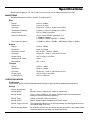
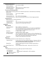
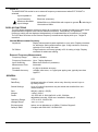
TG1006
10MHz DDS Function Generator
INSTRUCTION MANUAL
Table of Contents
Specifications
2
EMC
6
Safety
7
Installation
8
Connections
9
General
10
Standard Waveform Operation
11
Sweep
13
FSK
15
Store and Recall
16
LIST
17
Amplitude Modulation
17
External Counter
18
Calibration & Maintenance
18
This manual is 48591-1250 Issue 3
Note: The latest revision of this manual can be downloaded from:
http://tti1.co.uk/downloads/manuals-generator.htm
1
Specifications
Specifications apply at 18°- 28°C after one hour warm-up, at maximum output into 50Ω.
WAVEFORMS
Standard waveforms of Sine, Square, Triangle and DC.
Sine
Range:
1mHz to 10MHz.
Resolution:
1mHz or 6 digits.
Accuracy:
10 ppm for 1 year; ± 1mHz below 0.2Hz.
Temperature Stability:
Typically <1 ppm/ºC outside 18° to 28°C.
Output Level:
1mV to 10Vp−p into 50Ω.
Harmonic Distortion:
<0.3% THD to 20kHz (typically 0.1%).
<–45dBc to 300kHz.
<−30dBc to 10MHz (typically <−35dBc).
Non−harmonic Spurii:
<–55dBc to 1MHz, <–55dBc + 6dB/octave 1MHz to 10MHz.
Square
Range:
1mHz to 10MHz.
Resolution:
1mHz or 6 digits.
Symmetry Control:
20% to 80%, 1mHz to 10MHz.
Accuracy:
10 ppm for 1 year; ± 1mHz below 0.2Hz.
Output Level:
1mV to 10Vp−p into 50Ω.
Rise and Fall Times:
<25ns.
Aberrations:
<5% + 2mV.
Triangle
Range:
1mHz to 1 MHz.
Resolution:
1mHz or 6 digits.
Accuracy:
10 ppm for 1 year; ± 1mHz below 0.2Hz.
Output Level:
1mV to 10Vp−p into 50Ω.
Linearity Error:
<0.5% to 100 kHz.
OPERATING MODES
Continuous
Continuous cycles of the selected waveform are output at the programmed frequency.
Sweep
2
Carrier Waveforms:
All
Sweep Mode:
Manual, linear or logarithmic, single or continuous.
Sweep Width:
From 0.1Hz to 10MHz in one range. Phase continuous. Independent
setting of the start and stop frequency.
Sweep Time:
100ms to 999.99s (10ms resolution).
Sweep SYNC:
Start of sweep trigger available from SYNC output.
Sweep Trigger Source:
The sweep may be free run or a single sweep may be triggered from the
front panel MAN TRIG key.
Manual Sweep Mode:
An analogue control can be used to set the generator to any intermediate
frequency between the Start and Stop frequencies.
Amplitude Modulation
Carrier Frequency:
From 1mHz to 10MHz.
Carrier Waveforms:
All.
Modulation Frequency:
400Hz internal. DC to 20kHz external.
External Modulation:
AM/COUNT IN socket.
Frequency Shift Keying (FSK)
Phase coherent switching between two selected frequencies at a rate defined by the switching
signal source.
Carrier frequency:
From 0.1Hz to 10MHz.
Carrier waveforms:
All.
Switch repetition rate:
DC to 10kHz (internal trigger).
Switching signal source: Manual (front panel MAN TRIG key) or internal trigger generator.
Frequency List
Step through up to 10 stored frequencies.
Carrier Waveforms:
All.
Frequency List:
Up to 10 frequencies from 1mHz to 10MHz.
Switching Source:
Manual from front panel MAN TRIG key.
OUTPUTS
Main Outputs
Output Impedance:
50Ω and 600Ω (not independent).
Amplitude:
2mV to 20V pk-pk open circuit, (1mV to 10V pk-pk into 50Ω/600Ω) in
four switch selectable ranges with 20dB vernier control within each
range. Amplitude can be displayed in Vpk-pk or Vrms.
Attenuator:
0, -20dB, -40dB, or -60dB.
Amplitude Flatness:
±0.2dB to 500kHz; ±2dB to 10MHz.
DC Offset Range:
±10V. DC offset plus signal peak limited to ±10V from 50Ω/600Ω; CLIP
shows in display when offset plus signal peak exceeds ±10V. DC offset
plus waveform attenuated proportionally by the attenuator.
Resolution:
3 digits for both Amplitude and DC Offset.
SYNC Out
Automatically selected to be either Waveform Sync or Sweep Sync.
Waveform Sync:
A square wave at the main waveform frequency. Symmetry is 50% for
sine and triangle waves at MAIN OUT; for square waves symmetry is
the same as that of the waveform at MAIN OUT.
Sweep Sync:
Outputs a trigger signal at the start of sweep to synchronize an
oscilloscope.
Output Signal Level:
Output impedance 50Ω nominal. Logic levels of <0.8V & >3V.
INPUTS
AM In
The AM/COUNT IN socket is set to AM input when EXT AM is selected.
Input Impedance:
40kΩ.
Input Sensitivity:
Approximately 2V peak-peak for 100% modulation.
Maximum Allowable
Input Voltage:
±10V.
3
Count In
The AM/COUNT IN socket is set to external frequency measurement when EXT COUNT is
selected.
Input Impedance:
1MΩ//20pF.
Input Sensitivity:
50mVrms (sinewave).
Maximum Allowable
Input Voltage:
30Vdc/30Vrms to 50Hz/60Hz with respect to ground
1Vrms above 1MHz.
, reducing to
DISPLAY FUNCTIONS
The LCD shows generator frequency setting at a resolution of 4 digits simultaneously with output
amplitude/offset, together with various status annunciators. Alternatively, the generator
frequency setting can be displayed independently of amplitude/offset to a resolution of 6 digits.
The LCD also functions as the external frequency measurement display with up to 7 digits of
resolution.
Internal Measurement Accuracy
Amplitude:
Display shows peak-to-peak amplitude or rms value. Display corrected
for attenuator setting and waveform type. 3-digit resolution, accuracy
typically ±5% of range full scale.
DC Offset:
3-digit resolution; accuracy typically ±2% of setting ±1 digit. Display
corrected for attenuator setting.
External Frequency Measurement
Frequency Range:
3Hz to >120MHz.
Frequency Resolutuion: Up to 7 digits displayed.
Input Sensitivity:
Better than 50mVrms (sinewave).
Measurement Time:
Automatic.
Accuracy:
±1 digit ± timebase accuracy.
Timebase Accuracy:
<±5ppm initial error; <± 5 ppm/year ageing rate; typically less than
1ppm/°C.
GENERAL
Display:
Data Entry:
Stored Settings:
Size:
Weight:
Power:
Operating Range:
Storage Range:
Environmental:
Safety & EMC:
4
LCD.
Keyboard selection of mode; value entry direct by numeric keys or
by rotary control.
Up to 10 output frequencies may be stored and recalled from nonvolatile memory.
260(W) x 88(H) x 235(D)
1.45kg. (3.2lb.)
110-120V AC or 220V-240V AC ±10%, 50/60Hz,
adjustable internally; 35VA max. Installation Category II.
+5°C to 40°C, 20-80% RH.
-20°C to + 60°C.
Indoor use at altitudes up to 2000m, Pollution Degree 2.
Complies with EN61010-1 & EN61326.
EC Declaration of Conformity
We
Thurlby Thandar Instruments Ltd
Glebe Road
Huntingdon
Cambridgeshire PE29 7DR
England
declare that the
TG1006 10MHz Function Generator
meets the intent of the EMC Directive 2004/108/EC and the Low Voltage Directive 2006/95/EC.
Compliance was demonstrated by conformance to the following specifications which have been
listed in the Official Journal of the European Communities.
EMC
Emissions:
a) EN61326-1 (2006) Radiated, Class B
b) EN61326-1 (2006) Conducted, Class B
c) EN61326-1 (2006) Harmonics, referring to EN61000-3-2 (2006)
Immunity:
EN61326-1 (2006) Immunity Table 1, referring to:
a) EN61000-4-2 (2009) Electrostatic Discharge
b) EN61000-4-3 (2006) Electromagnetic Field
c) EN61000-4-11 (2004) Voltage Interrupt
d) EN61000-4-4 (2004) Fast Transient
e) EN61000-4-5 (2006) Surge
f)
EN61000-4-6 (2009) Conducted RF
Performance levels achieved are detailed in the user manual.
Safety
EN61010-1 Installation Category II, Pollution Degree 2.
CHRIS WILDING
TECHNICAL DIRECTOR
2 January 2013
5
EMC
This instrument has been designed to meet the requirements of the EMC Directive 2004/108/EC.
Compliance was demonstrated by meeting the test limits of the following standards:
Emissions
EN61326-1 (2006) EMC product standard for Electrical Equipment for Measurement, Control and
Laboratory Use. Test limits used were:
a)
Radiated:
Class B
b)
Conducted: Class B
c)
Harmonics: EN61000-3-2 (2006) Class A; the instrument is Class A by product category.
Immunity
EN61326-1 (2006) EMC product standard for Electrical Equipment for Measurement, Control and
Laboratory Use.
Test methods, limits and performance achieved are shown below (requirement shown in
brackets):
a)
EN61000-4-2 (2009) Electrostatic Discharge : 4kV air, 4kV contact, Performance A (B).
b)
EN61000-4-3 (2006) Electromagnetic Field: 3V/m, 80% AM at 1kHz, 80MHz – 1GHz:
Performance B† (A) and 1.4GHz to 2GHz: Performance A (A); 1V/m, 2.0GHz to 2.7GHz:
Performance A (A).
c)
EN61000-4-11 (2004) Voltage Interrupt: ½ cycle and 1 cycle, 0%: Performance A (B);
25 cycles, 70% : Performance A(C) and 250 cycles, 0%: Performance B (C).
d)
EN61000-4-4 (2004) Fast Transient, 1kV peak (AC line only; signal connections <3m,
therefore not tested††) Performance A (B).
e)
EN61000-4-5 (2006) Surge, 0·5kV (line to line), 1kV (line to ground), Performance A (B).
f)
EN61000-4-6 (2009) Conducted RF, 3V, 80% AM at 1kHz (AC line only; signal
†
connections <3m, therefore not tested ), Performance A (A).
†
In a sufficiently large RF field at 80-90MHz, the generator output may be affected such that the
signal fidelity marginally fails specification limits; however, in all other respects the instrument will
operate correctly (Performance A) in fields up to 3V/m.
††
Signal lines were not tested on the basis that typical use will be with connections <3m, for
which there is no test requirement. Immunity performance with connections >3m is not
guaranteed.
According to EN61326-1 the definitions of performance criteria are:
Performance criterion A: ‘During test normal performance within the specification limits.’
Performance criterion B: ‘During test, temporary degradation, or loss of function or
performance which is self-recovering’.
Performance criterion C: ‘During test, temporary degradation, or loss of function or
performance which requires operator intervention or system reset occurs.’
Cautions
To ensure continued compliance with the EMC directive observe the following precautions:
a) Connect the generator to other equipment using only high quality, double−screened cables.
This instrument met the Class B emission limits with the 50Ω Main Output connected via 1m coax
to a 50Ω load; note that emission levels may be higher when connected to a test system.
b) After opening the case for any reason, ensure that all signal and ground connections are
remade correctly and that the case screws are correctly fitted and tightened.
6
Safety
This instrument is Safety Class I according to IEC classification and has been designed to meet
the requirements of EN61010-1 (Safety Requirements for Electrical Equipment for Measurement,
Control and Laboratory Use). It is an Installation Category II instrument intended for operation
from a normal single phase supply.
This instrument has been tested in accordance with EN61010-1 and has been supplied in a safe
condition. This instruction manual contains some information and warnings which have to be
followed by the user to ensure safe operation and to retain the instrument in a safe condition.
This instrument has been designed for indoor use in a Pollution Degree 2 environment in the
temperature range 5°C to 40°C, 20% - 80% RH (non-condensing). It may occasionally be
subjected to temperatures between +5°C and –10°C without degradation of its safety. Do not
operate while condensation is present.
Use of this instrument in a manner not specified by these instructions may impair the safety
protection provided. Do not operate the instrument outside its rated supply voltages or
environmental range.
WARNING! THIS INSTRUMENT MUST BE EARTHED
Any interruption of the mains earth conductor inside or outside the instrument will make the
instrument dangerous. Intentional interruption is prohibited. The protective action must not be
negated by the use of an extension cord without a protective conductor.
When the instrument is connected to its supply, terminals may be live and opening the covers or
removal of parts (except those to which access can be gained by hand) is likely to expose live
parts. The apparatus shall be disconnected from all voltage sources before it is opened for any
adjustment, replacement, maintenance or repair.
Any adjustment, maintenance and repair of the opened instrument under voltage shall be
avoided as far as possible and, if inevitable, shall be carried out only by a skilled person who is
aware of the hazard involved.
If the instrument is clearly defective, has been subject to mechanical damage, excessive
moisture or chemical corrosion the safety protection may be impaired and the apparatus should
be withdrawn from use and returned for checking and repair.
Make sure that only fuses with the required rated current and of the specified type are used for
replacement. The use of makeshift fuses and the short-circuiting of fuse holders is prohibited.
Do not wet the instrument when cleaning it.
The following symbols are used on the instrument and in this manual:Caution - refer to the accompanying documentation, incorrect operation
may damage the instrument.
terminal connected to chassis ground.
alternating current.
7
Installation
Mains Operating Voltage
The operating voltage of the instrument is shown on the rear panel. Should it be necessary to
change the operating voltage from 230V to 115V or vice-versa, proceed as follows:
1.
Disconnect the instrument from all voltage sources.
2.
Unclip the front bezel by gently pulling the centre of each long edge up and forward.
The case halves are held together by 4 plastic push-rivets. Use the blade of a small screwdriver
in the slot beside each rivet to first ease out the rivet head and then fully remove the rivet body.
Separate the case halves. Visit www.tti-test.com for further details.
3.
Remove the 6 screws securing the main pcb to the case upper and lift the pcb free,
complete with front and rear panels.
4.
Change the appropriate zero-ohm links beside the transformer on the pcb:
Link LK2 only for 230V operation
Link LK1 and LK3 only for 115V operation
5.
Refit the pcb to the case upper, ensuring all connections (especially safety earth) are
remade as before, and refit the case lower.
6.
To comply with safety standard requirements the operating voltage marked on the rear
panel must be changed to clearly show the new voltage setting.
7.
Change the fuse to suit the new operating voltage, see below.
Fuse
The correct time-lag fuse must be fitted for the selected operating voltage.
For 230V operation use 125mA (T) 250V HBC.
For 115V operation use 250mA (T) 250V HBC.
Make sure that only fuses with the required rated current and of the specified type are used for
replacement. The use of makeshift fuses and the short-circuiting of fuse holders are prohibited.
Mains Lead
Connect the instrument to the AC supply using the mains lead provided. Should a mains plug be
required for a different mains outlet socket, a suitably rated and approved mains lead set should
be used which is fitted with the required wall plug and an IEC60320 C13 connector for the
instrument end. To determine the minimum current rating of the lead-set for the intended AC
supply, refer to the power rating information on the equipment or in the Specification.
WARNING! THIS INSTRUMENT MUST BE EARTHED
Any interruption of the mains earth conductor inside or outside the instrument will make the
instrument dangerous. Intentional interruption is prohibited.
8
Connections
MAIN OUT (50Ω and 600Ω)
This is the main output from the generator with an output source impedance of either 50Ω or 600Ω;
the outputs are not independent. Either output will provide up to 20V peak−to−peak e.m.f. which
will give 10V peak-to-peak into a matched load. The outputs can tolerate a short circuit for 10
minutes.
Do not apply external voltages to these outputs.
SYNC
Automatically selected to be either Waveform Sync or Sweep Sync.
Waveform Sync:
A square wave at the main waveform frequency. Symmetry is 50%
for sine and triangle waves at MAIN OUT; for square waves
symmetry is the same as that of the waveform at MAIN OUT.
Sweep Sync:
Outputs a trigger signal at the start of sweep to synchronize an
oscilloscope.
Output Signal Level:
Output impedance 50Ω nominal. Logic levels of <0.8V & >3V.
SYNC will withstand a short circuit.
Do not apply an external voltage to this output.
AM/COUNT IN
The AM/COUNT IN socket is set to external frequency measurement when the EXT COUNTER
switch is ON
.
Input Impedance:
1MΩ//20pF.
Input Sensitivity:
50mVrms (sinewave).
Maximum Allowable
Input Voltage:
30Vdc/30Vrms to 50Hz/60Hz with respect to ground
to 1Vrms above 1MHz.
, reducing
The AM/COUNT IN socket is set to AM input when EXT AM is selected (EXT COUNTER switch
OFF
).
Input Impedance:
40kΩ.
Input Sensitivity:
Approximately 2V peak-peak for 100% modulation.
Maximum Allowable
Input Voltage:
±10V.
9
General
This section is a general introduction to the organisation of the instrument and is intended to be
read before using the generator for the first time. Detailed operation is covered in later sections
starting with Standard Waveform Operation.
In this manual front panel controls and sockets are shown in capitals, e.g. AM DEPTH, MAIN
OUT; parameter values and messages displayed on the LCD are shown in a different type−font,
e.g. SWP-LOG, Func oFF.
DDS Principles
In this instrument waveforms are generated by Direct Digital Synthesis (DDS). A phase
accumulator is incremented at a rate proportional to the required output frequency. The most
significant 12 bits of the accumulator are used to address a look-up table ROM that converts the
phase information into sinewave amplitude data; this data is then passed to a 10-bit Digital-toAnalogue Converter (DAC) which produces the output waveform. For triangle waves the ROM
look-up table is by-passed and the phase accumulator output is passed directly to the DAC.
At low frequencies all 4096 points in the output wave are stepped through, but as the frequency
increases points are progressively missed out. Sinewaves and triangles are subsequently filtered
to smooth the steps in the DAC output; this technique ensures good sinewave purity up to the
maximum frequency of the generator but the practical limit to which excellent triangle linearity is
maintained is only about 100kHz. Squarewaves and pulses are derived from the sinewave using
a variable threshold comparator; this permits symmetry control of these waveforms across the
whole instrument frequency range.
The major advantages of DDS over conventional analogue generation are:
• Frequency accuracy and stability is that of the crystal oscillator.
• Frequencies can be set with high resolution from mHz to MHz.
• Low phase noise and distortion.
• Very wide frequency sweeps are possible.
• Fast phase continuous frequency switching.
Switching On
Switch on the generator using the POWER ON/OFF switch on the rear panel. To fully disconnect
from the AC supply unplug the mains cord from the back of the instrument or switch off at the AC
supply outlet; make sure that the means of disconnection is readily accessible. Disconnect from
the AC supply when not in use.
Ensure that the push-button switches in the AMPLITUDE MOD and EXT COUNTER sections of
the control panel are all set to the out ( ) position and that Sweep, FSK and List operating
modes (see below) are not enabled, i.e. set the generator to its normal free run mode; select
sinewave on the FUNCTION buttons. The display will show the frequency and peak-to-peak
output amplitude with appropriate range annunciators.
Shift Functions
This instrument has shift functions to select (and set up) Sweep, FSK, List, Store and Recall;
press SHIFT (the display shows SHIFt) followed by the required function or parameter. Sweep,
FSK and List are defined as operating modes and as such must be enabled and disabled. It is
only possible to run one of these operating modes at any given time; enabling a second
operating mode will disable the first. For confirmation, whenever an operating mode is enabled
or disabled a notification is displayed momentarily, e.g. LISt on is displayed when Frequency List
is enabled. If an operating mode was already running, this is turned off before the new function
is enabled and the display shows, for example, FS oFF (if FSK was running) before LISt on is
displayed. All shift function operating mode parameters e.g. SWEEP TIME, sweep START
frequency, etc., can be set whilst any of the shift function operating modes are enabled or whilst
all are disabled. When a shift function operating mode parameter is set, donE is displayed.
10
Data Retention at Power-down
Whenever the instrument is switched off the following parameters are stored to non-volatile
memory: main generator frequency, the 10 user-defined frequencies, sweep time, sweep start
and stop frequencies, lin or log selection, FSK frequencies F0 & F1, and the FSK rate.
Standard Display Screens
The instrument has 3 standard display screens • High resolution frequency display and entry – accessed by pressing the FREQ key and
used to edit and display the continuous generator output frequency at a higher resolution
of 6 digits. This screen is not available whilst any of the shift function operating modes
are enabled.
• Amplitude level with lower resolution frequency display – accessed by pressing the PKPK/RMS key and used to display the main output amplitude level in either peak-to-peak
volts or r.m.s volts, together with the generator output frequency at a lower resolution of 4
digits. This is the default screen at power-up.
• Offset level with lower resolution frequency display – accessed by pressing the OFFSET
key and used to display the main output offset level together with the generator output
frequency at a lower resolution of 4 digits.
Note: The user has the choice between the amplitude and offset screens when any of the shift
function operating modes are enabled.
Standard Waveform Operation
Frequency Setting
Pressing the FREQ key displays the high resolution frequency screen. The frequency can be
entered directly from the keyboard in any convenient units, e.g. 12.34kHz can be entered directly
in kHz but can also be entered as 12340Hz or 0.01234MHz. Display annunciators show Hz, kHz
or MHz. The CE key deletes the last digit that was entered and the ESCAPE key returns to the
high resolution frequency screen, leaving the generator frequency unchanged. Pressing the JOG
key enables the Jog capability. When Jog is enabled, turning the rotary control will increment or
decrement the numeric value in steps determined by the position of the edit cursor (blinking
digit); the cursor is moved by one digit to the left each time the JOG key is pressed. Once the
edit cursor position reaches the first digit, the next press of JOG returns the cursor to the last
digit. The JOG function can be disabled by pressing the JOG OFF key thus disabling the rotary
control and avoiding accidental unwanted modification of the generator frequency.
Note that pressing the FREQ key not only allows for frequency entry but also terminates/disables
any shift function operating mode that may be enabled. This provides a quick method of
returning to a continuous fixed frequency operating mode.
Waveform
The output waveform shape is selected by depressing one of the three function buttons to give
sine, square or triangle. With all three switches out (accomplished by half-depressing any one)
the output will be a DC level only; this is useful as it permits input threshold testing of a circuit
without having to connect up an external DC supply.
When the square waveform is selected, SYMMETRY is enabled and the SYMMETRY control can
be used to vary the duty cycle from 20% to 80% to produce variable pulse-width waveforms
(centre detent for 50% duty). When SYMMETRY is enabled the SYM annunciator is displayed.
Amplitude
The amplitude of the MAIN OUT output is set by the AMPLITUDE control and the ATTENUATOR
switches. Maximum output is 20 volts peak-to-peak open-circuit, 10 volts peak-to-peak when
terminated with the outputs characteristic impedance.
The AMPLITUDE control has greater than 20dB range; the ATTENUATOR switches permit
selection of up to -60dB attenuation (both switches pressed together). Used together these
11
controls provide a range of 20V peak-to-peak down to 2mV peak-to-peak, or 10V peak-to-peak
down to 1mV peak-to-peak into the output’s characteristic impedance.
Still greater attenuation of the 50Ω MAIN OUT can be achieved by using standard 50Ω BNC
attenuators. To maintain waveform integrity only 50Ω cable should be used and the receiving
end should be terminated with a 50Ω load.
The MAIN OUT outputs will withstand a short circuit for a period of 10 minutes at maximum
output and greater periods at lower output levels. However, damage will occur if an external
voltage is connected to the output sockets. The 50Ω and 600Ω outputs are not independent;
terminating one will affect the amplitude of the other.
The amplitude is displayed on the right-hand side of the LCD; the PK-PK/RMS key alternates the
reading between peak-to-peak volts and r.m.s. volts; display annunciators give the units as Vp-p,
mVp-p, Vrms or mVrms. The readout is correctly adjusted for attenuator setting and waveform
shape. The display shows open circuit voltage; the actual voltage at the socket will be half the
displayed value when the output is terminated with its characteristic impedance.
DC Offset
The DC OFFSET control has a range of ±10 volts from 50Ω/600Ω in all output modes; the control
has a centre detent for 0 volts. DC offset plus signal peak is limited to ±10V (±5V into the
characteristic output impedance); CLIP shows in the display when this limit is exceeded.
DC offset plus waveform is attenuated proportionally by the ATTENUATOR switches.
The DC offset can be displayed in place of the output amplitude by pressing the OFFSET key.
The display shows open circuit voltage offset (in Volts) and a DC annunciator; the actual voltage
at the socket will be half the displayed value when the output is terminated with its characteristic
impedance.
SYNC Output
The SYNC output provides a TTL/CMOS level output that is automatically switched between the
following:
• Waveform sync:
A sync signal phase coincident with the MAIN OUT waveform. For
sine and triangle waves the sync waveform rising edge is at the 0º
phase point of MAIN OUT and the falling edge is at the 180º phase
point. For square waves and pulses both phase and symmetry are
coincident with MAIN OUT.
• Sweep sync:
Outputs a trigger signal at the start of sweep with a width of half of
the total sweep (midpoint) to synchronize an oscilloscope.
Error Messages
An error message (Error) is shown in the display when an illegal setting is attempted, most
generally a number outside the range of values permitted.If this occurs whilst the main generator
frequency is being set then the entry is rejected and the frequency setting is left unchanged.
However if this occurs whilst a shift function operating parameter is being set, the value is set to
the maximum or minimum value permitted accordingly:
Entered value <Range minimum: value is set to the minimum range value.
Entered value >Range maximum: value is set to the maximum range value.
An error message is also shown if the Triangle waveform is selected whilst the MAIN output
frequency is greater than 1MHz; this will result in the frequency being set to 1MHz. However
such a condition is also possible during any shift function operating mode or even during
frequency counter mode; if such a condition does occur then the main output frequency and
appropriate shift function operating mode parameters are changed automatically. For further
information on the outcome of such a condition or other possible error conditions see Sweep,
FSK, Save and Recall and Frequency Counter sections.
During an error message the buzzer sounds twice to indicate that an error has occurred.
12
Sweep
Principles of Sweep Operation
All waveforms can be swept phase-continuously from 0.1Hz up to the maximum frequency for the
selected waveform. Although the frequency is stepped, not truly swept as in an analogue
generator, the short step interval (500us) gives a close approximation to an analogue instrument
except for the widest sweeps in the shortest time; see the Frequency Stepping Resolution section
for further discussion.
The frequency steps are calculated and updated in real-time at a rate of 2kHz with full precision,
following either a linear or log sweep law as selected by the user.
Sweep mode is turned on and off by pressing the SHIFT key followed by SWEEP (numeric key
7) on the keyboard; the SWP annuciator shows in the display. This is the only method for
enabling sweep mode; however, disabling sweep mode is additionally possible by either enabling
an alternative operating mode (FSK or LIST) or by pressing the FREQ key which disables all shift
functions.
Sweep Range
The maximum sweep range for all waveforms is 0.1Hz to 10MHz, except triangle (up to 1MHz).
The Sweep range is defined by start and stop frequencies which set the two end points of the
sweep. These points are entered directly from the numeric keyboard with a resolution of 0.1Hz.
The sweep function has the capability of sweeping either up or down in frequency; the sweep
direction is determined by the sweep start and stop frequencies as the sweep will always run
from the start frequency to the stop frequency. Thus, setting the stop frequency to a value that is
greater than the start frequency results in an upward sweep whereas setting the stop frequency
to a value that is less than the start frequency results in a downward sweep.
The start and stop frequencies can be checked and updated by pressing the SHIFT key followed
by either START (numeric key 5) or STOP (numeric key 6) respectively. When either the start or
stop frequency are selected the current frequency is displayed to a 4 digit resolution; this value
can then be modified via direct keyboard entry or be left unchanged by pressing SHIFT, ESCAPE
or any of the display screen keys (FREQ, PK-PK/RMS or OFFSET).
Sweep Time
The sweep time can be set from 0·1s to 999.99s with 10ms resolution by direct keyboard entry.
The shortest sweep times will have the fewest steps (a 100ms sweep will have only 200 steps
whereas a 10s sweep will have 20,000 steps) and will consequently have a coarse stepping
resolution with very wide sweeps, see Frequency Stepping Resolution section for more
discussion.
The sweep time can be checked and updated by pressing the SHIFT key followed by SWEEP
TIME (numeric key 4). Upon selection of the sweep time the current sweep time value is
displayed to a 10ms resolution (or 5 digits). This value can then be modified via direct keyboard
entry or be left unchanged by pressing SHIFT, ESCAPE or any of the display screen keys.
LIN / LOG Selection
The sweep function has the capability for producing a swept output that follows either a linear or
log sweep law as selected by the user. Selection between LIN and LOG is performed by
pressing the SHIFT key followed by LIN (numeric key 8) or LOG (numeric key 9) for a linear or
logarithmic sweep respectively. This is a toggle selection so selecting one also deselects the
other.
If the sweep function is enabled then the LIN or LOG annunciator will be displayed accordingly.
13
Manual Sweep
When the sweep function operating mode is enabled, its default condition of manual sweep is
initialised. This allows the user to manually sweep from the start frequency to the stop frequency
using the MANUAL SWEEP control. Manual sweep provides a total of 510 frequency steps
between the start and stop frequencies. The frequency of the current step of the sweep is
displayed with a resolution of 4 digits. The frequency can be manually swept following either a
linear or logarithmic sweep law; its current value can also be stored using the store function, see
Store and Recall section for more discussion. If the Triangle waveform is selected and the
manual sweep frequency is taken beyond the 1MHz limit, an error message is displayed and the
start and stop frequencies are adjusted accordingly to be limited to a maximum frequency of
1MHz.
Sweep Triggering
When the sweep function operating mode is enabled and in its default setting i.e. manual sweep
mode, the user can select between either a single or continuous sweep. A single sweep is
initialised by pressing the MAN TRIG key; this produces a single sweep from the start frequency
to the stop frequency in the defined sweep time. Upon completion of the sweep the instrument
returns to manual sweep mode at the frequency step determined by the position of the MANUAL
SWEEP control. Continuous sweep mode is initialised by pressing the RUN key; this produces
continuous sweeps between the start and stop frequencies in the defined sweep time. During a
running sweep (either single or continuous) an indication of the current sweep frequency is
displayed to a resolution of 4 digits at an update rate of 8Hz, unless a sweep time of less than or
equal to one second is defined, in which case run is displayed because the frequency changes
are too fast to display meaningfully. If Triangle waveform is selected and the current sweep
frequency is above the 1MHz limit, an error message is displayed and the start and stop
frequencies are adjusted accordingly to be limited to a maximum frequency of 1MHz.
Pressing either the MAN TRIG or RUN key whilst a single or continuous sweep is running results
in the termination of the running sweep and the instrument returns to manual sweep mode at the
frequency step determined by the position of the MANUAL SWEEP control.
Sweep Sync
Sweeps are generally used with an oscilloscope or hard−copy device to investigate the frequency
response of a circuit. The MAIN OUT is connected to the circuit input and the circuit output is
connected to an oscilloscope or, for slow sweeps, a recorder. An oscilloscope can be triggered
by connecting its trigger input to the generator’s SYNC ouput; the SYNC output defaults to a
Sweep Sync when a sweep is running (either continuous or single sweep). Sweep Sync goes
high at the start of sweep and low half way through the sweep. In manual sweep mode the
SYNC output reverts to its default state of Waveform Sync and outputs a signal that is phase
coincident with the MAIN OUT waveform.
Frequency Stepping Resolution
The generator frequency is stepped, not truly linearly swept, between the Start and Stop
frequencies. The number of discrete frequency steps in a sweep is determined by the sweep
time set; the size of each step, i.e. the frequency stepping resolution, is determined by the
number of steps and the sweep range (difference between the Start and Stop frequencies). At
the shortest sweep times ( i.e. the fewest steps) with the widest frequency spans the frequency
changes will be quite large at each step; if the output is applied to a filter, for example, the
response will be a succession of step-change levels with (at higher frequencies) many cycles of
the same frequency at each step. This is a limitation of a DDS generator in sweep mode but in
part, of course, this effect can only be created because of the very wide sweeps that can be
achieved with DDS techniques; analogue generators usually have more restricted capabilities.
14
FSK
General
FSK (Frequency Shift Keying) mode permits fast phase-continuous switching between two
frequencies within the range of 0.1Hz to 10MHz at a rate of up to 10kHz. All other parameters of
the waveform (amplitude, offset, symmetry) remain the same as the freq uency is switched.
FSK mode is turned on and off by pressing the SHIFT key followed by FSK (numeric key 1);
FS on momentarily shows in the display when it is turned on, and FS oFF shows when it is
turned off. This is the only method for enabling FSK mode; however, disabling FSK mode is
additionally possible by either enabling an alternative operating mode (SWEEP or LIST) or by
pressing the FREQ key which disables all shift functions.
Frequency Setting
The two frequencies F0 and F1, between which the waveform is switched, are checked and
updated by pressing the SHIFT key followed by F0/F1 (numeric key 2). This will display either F0
or F1 and its corresponding current frequency to a resolution of 4 digits. Switching between the
F0 and F1 frequency information is achieved with alternate presses of the MAN TRIG key. This
frequency value can then be modified via direct keyboard entry or be left unchanged by pressing
SHIFT, ESCAPE or any of the display screen keys (FREQ, PK-PK/RMS or OFFSET).
Rate Setting
The waveform can be continuously switched between the two frequencies F0 and F1 at a rate
defined by the rate entry. This rate can be set within the range of 0.1ms to 100s at a resolution
of 0.1ms. The FSK rate can be checked and updated by pressing the SHIFT key followed by
RATE (numeric key 3). Upon selection of the FSK rate the current FSK rate is displayed to a 5
digit resolution in seconds (indicated by an S following the value). This value can then be
modified via direct keyboard entry or be left unchanged by pressing SHIFT, ESCAPE or any of
the display screen keys.
FSK Triggering
Frequency shift keying between frequencies F0 and F1 can either be achieved manually with
alternate presses of the MAN TRIG key or can be switched at the user-defined FSK rate by
pressing the RUN key. When manually switching, the frequency currently selected is displayed
to a resolution of 4 digits. When switching at the rate defined by the user, run is displayed
because the frequency is generally changing too fast to read. When running at the FSK rate a
second press of the RUN key halts the running.
15
Store and Recall
General
Store and Recall functions permit up to 10 user-defined frequencies be saved to, and restored
from, non-volatile memory, with no limit to the number of overwrites to each memory location.
The stored values can be any frequency within the range of 1mHz to 10MHz.
Store
Storing a frequency value is initiated by pressing the SHIFT key followed by STORE (numeric
key 0). Confirmation of the intention to store a frequency value is requested by displaying
StorE ; this remains displayed until a memory location from 0-9 is selected at which the
frequency value will be stored. When a location is selected using keys 0-9 the display
momentarily shows the confirmation message donE before returning to the standard display
screen. A second store operation to the same location overwrites the data at that location with
the new data. The store function is able to not only store the continuous generator frequency but
also the current manual sweep frequency and both FSK frequencies, by using the same method
in both the Sweep and FSK functions respectively. It is not capable of storing a running sweep
(single or continuous) frequency value or an FSK frequency value whilst FSK is running at the
user-defined rate; attempting either results in the Error message.
Erase
A stored frequency value can be erased from memory by initiating the Store function (SHIFT key
then STORE), followed by a single press of the CE key. Confirmation of the intention to erase a
stored frequency value is requested by displaying ErASE; this remains displayed until the
memory location (0-9) to be erased is selected by pressing the appropriate numeric key. By
pressing 0, for example, the frequency value that is stored in location 0 is erased; recalling from
this location will then return null, see below.
Recall
A frequency value can be recalled by pressing the SHIFT key followed by RECALL (.).
Confirmation of the intention to recall a frequency value is requested by displaying rECALL; this
remains displayed until the memory location (0-9) containing the required frequency is selected
by pressing the appropriate numeric key. The frequency stored in the selected location is
recalled and used as the continuous generator frequency. Recalling from a memory location
that has no stored frequency value results in null being displayed momentarily and the generator
frequency is left unchanged. Recall cannot be used whilst Sweep or FSK operating modes are in
use; attempting either results in the Error message.
16
LIST
General
Frequency LIST mode permits stepping through a list of up to 10 user-defined frequency values.
These frequency values are the ones saved by the user in memory locations 0-9 using the Store
function; see Store and Recall section for more discussion.
LIST mode is turned on and off by pressing the SHIFT key followed by LIST (the CE key); LISt
on momentarily shows in the display when it is turned on, and LISt oFF shows when it is turned
off. This is the only method for enabling LIST mode; however, disabling LIST mode is
additionally possible by either enabling an alternative operating mode (SWEEP or FSK) or by
pressing the FREQ key which disables all shift functions.
Step
Stepping through the list can only be executed in one direction, from 0 to 9 (increment), and is
performed by pressing the MAN TRIG key. Once the current step reaches the last stored
frequency value, one further step causes a loop back to the first stored frequency value. The
function only steps through memory locations with stored frequencies; therefore, if only memory
locations 0 and 2 (for example) have frequencies stored, the list function will only step between
these two frequencies. All other memory locations are read as null and therefore skipped.
It is also possible to skip to a specific memory location within the LIST function by recalling the
desired memory location using the Recall function (see Store and Recall section for more
information); the LIST function will then increment from this point onwards.
Amplitude Modulation
Depressing the AM ON/OFF button selects AM. The depth of modulation can be adjusted over a
0% to 100% range using the AM DEPTH control. When AM is selected the output amplitude will
drop to 50% at 0% modulation.
With the AMPLITUDE MOD INT/EXT button in the INT (internal) position, the modulation source
is an internal 400Hz sinewave oscillator. The INT-AM annunciator is displayed.
With the AMPLITUDE MOD INT/EXT button in the EXT (external) position, and the EXT
COUNTER ON/OFF button in the OFF (EXT AM) position, external AM modulation is possible via
the AM/COUNT IN socket; the AM-EXT annunciator is displayed. The modulating signal applied
should have no DC offset or should be AC coupled. A 2V peak-to-peak signal gives
approximately 100% modulation with the modulation control at maximum. Modulating the
generator with a squarewave gives step changes in the output amplitude which are suitable for
testing signal compressors and automatic gain controlled circuits.
Applying a DC offset of approximately −1V gives suppressed carrier modulation. The DC offset
should first be adjusted to suppress the carrier, and the modulating signal then applied.
Applying a DC offset greater than −1V will invert the MAIN OUT outputs with respect to the SYNC
output.
The generator can also be asynchronously gated on and off using the AM facility. Select EXT AM
and apply a suitably offset squarewave to the AM/COUNT IN input. The squarewave Vlow should
be approximately −1V to give carrier suppression and the Vhigh should be +3V to +4V to give
normal full output.
17
External Counter
Selecting EXT COUNTER ON sets the COUNT IN socket to external frequency measurement.
The display changes to show a 6/7-digit frequency measurement and the EXT annunciator shows
in the display to indicate external measurement.
Note: With no input signal present the counter displays 00. until an adequate input signal is
applied.
In external counter mode the COUNT IN socket has an impedance of 1MΩ in parallel with 20pF.
Input frequency range is 3Hz to >120MHz (typically 150MHz).
Care should be taken when measuring input signals above 350mV rms (the onset of diode
clipping) with poor signal to noise ratios as under these circumstances it is possible for noise to
generate spurious counts. To ensure a correct count, therefore, noisy signals should be
attenuated externally before being presented to the counter. A convenient attenuation factor of
10 can be achieved by the use of a x10 oscilloscope probe.
The function generator continues to perform normally when EXT COUNT is selected; however,
all keyboard keys are disabled, leaving the generator fixed in its last set condition prior to
enabling the counter. Due to the continuation of normal generator operation whilst in external
count mode, selecting the triangle waveform when the main output frequency exceeds 1MHz still
results in an error condition. Thus an error message interrupts the count and the main output
frequency and any appropriate shift function operating mode parameters are updated.
Calibration & Maintenance
Calibration
The DDS generator and external frequency meter use a crystal oscillator reference which is
factory adjusted to meet the initial accuracy specifications. However, crystal ageing will affect the
long-term accuracy and the reference should be re-adjusted annually to ensure continued
compliance with the accuracy specifications, see below.
Maintenance
The Manufacturers or their agents overseas can provide a routine calibration service and also a
repair service for any unit developing a fault. Where owners wish to undertake their own
maintenance work, this should only be done by skilled personnel in conjunction with the Service
Guide which may be obtained directly from the Manufacturers or their agents overseas.
Cleaning
If the instrument requires cleaning use a cloth that is only lightly dampened with water or a mild
detergent.
WARNING! TO AVOID ELECTRIC SHOCK, OR DAMAGE TO THE INSTRUMENT, NEVER
ALLOW WATER TO GET INSIDE THE CASE. TO AVOID DAMAGE TO THE CASE NEVER
CLEAN WITH SOLVENTS.
18
Thurlby Thandar Instruments Ltd.
Glebe Road • Huntingdon • Cambridgeshire • PE29 7DR • England (United Kingdom)
Telephone: +44 (0)1480 412451 • Fax: +44 (0)1480 450409
International web site: www.aimtti.com • UK web site: www.aimtti.co.uk
Email: [email protected]
Aim Instruments and Thurlby Thandar Instruments
Book Part No. 48591-1250 Issue 3