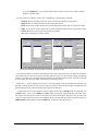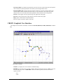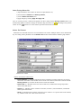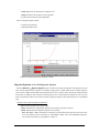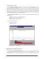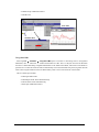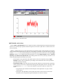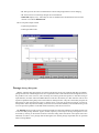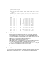
1
Columbia River Salmon Passage Model CRiSP.1.6 User Manual Date: March 13, 2002 3:29 pm Developed by the Columbia Basin Research School of Aquatic & Fishery Sciences University of Washington Contributors This model was developed as a team effort involving scientists, managers and computer programmers. Authors James Anderson - Principal Investigator, UW W. Nicholas Beer Joshua Hayes Susannah Iltis Matthew Moore David Salinger Pamela Shaw Richard Zabel Acknowledgments We wish to thank the following people for their support and suggestions in the development of this model. David Askren - BPA Dale Johnson - BLM Albert E. Giorgi - Don Chapman and Associates James Geiselman - BPA Funding Model development was funded by the Bonneville Power Administration Under Contract Contract Number: DE-BI79-89BP02347 Project Number: 89-108 <!Page 1> Table of Contents Introduction ......................................................................................................................6 General Description .................................................................................................6 CRiSP.1 in Context with Other Models...................................................................8 CRiSP.1 in the Decision Making Process ................................................................9 Fish Passage in CRiSP.1 ........................................................................................10 Species and Stocks ......................................................................................10 Passage Algorithms .....................................................................................10 Survival and Migration................................................................................11 CRiSP.1 Submodels ...............................................................................................12 Calibration Issues ...................................................................................................14 Getting Started...............................................................................................................16 Installation..............................................................................................................16 Internet Access and Communication...........................................................16 Windows 95/NT Installation .......................................................................16 Minimum System Requirements ...................................................16 Download and Install .....................................................................16 Unix Installation ..........................................................................................17 Minimum System Requirements ...................................................17 Download and Install .....................................................................17 Required Files .............................................................................................17 Starting CRiSP.1 ....................................................................................................18 Starting from the Desktop (Windows 95/NT).............................................18 Starting from the Command Prompt ...........................................................19 Running in Batch Mode ..............................................................................20 Unix ...............................................................................................20 Windows 95/NT.............................................................................21 CRiSP.1 Files .........................................................................................................21 River Description File .................................................................................21 Yearly Input Data File.................................................................................22 Model Parameter Data Files..................................................................23 Control File ...........................................................................................24 Flow Archive File........................................................................................25 Output Files and Directories .......................................................................25 Reading Data into CRiSP.1.........................................................................26 Standard CRiSP.1 Features ....................................................................................27 Standard Window Features .........................................................................28 Menus and Submenus..................................................................................28 Help Tools ...................................................................................................28 Two Level Editing and Display ..................................................................28 Slider Input ..................................................................................................30 Slider Input Window Features ..............................................................31 Edit Single Slider Value ................................................................31 Edit Multiple Slider Values Simultaneously .................................33 Edit All Slider Values Simultaneously ..........................................33 Slider Input Additional Features....................................................34 Editable Graph.............................................................................................34 Editable Graph Window Features .........................................................34 Editable Graph Viewing Features..................................................35 Editable Graph Input Features .......................................................36 1 CRiSP.1 Editable Graph Additional Features ..............................................36 Schedule Tool..............................................................................................36 Create a New Period ......................................................................36 Modify an Existing Period .............................................................37 Julian Day Output........................................................................................37 Julian Day Output Window Features ....................................................38 Julian Day Output Viewing Features.............................................38 Julian Day Output Additional Features .........................................39 Equation Input .............................................................................................39 Equation Input Features .................................................................40 CRiSP.1 Graphical User Interface .........................................................................41 River Map....................................................................................................42 File...............................................................................................................43 Open ......................................................................................................43 Save As .................................................................................................44 Print Map...............................................................................................44 Mouse Tool ...........................................................................................44 Message Log .........................................................................................45 Exit ........................................................................................................46 View ............................................................................................................46 UnZoom ................................................................................................46 Grid .......................................................................................................47 Map .......................................................................................................47 Release ........................................................................................................47 New .......................................................................................................47 Release Tool..........................................................................................47 Open Release Tool.........................................................................48 Create New Release .......................................................................48 Delete Existing Release Site ..........................................................49 Release Tool Features....................................................................49 Release Schedule...................................................................................50 Reservoir .....................................................................................................51 Reach Predator Density .................................................................51 Predator Distribution Coefficient..........................................................52 Reach Gas Theta ...................................................................................53 Gas Distribution ....................................................................................54 TDG Saturation > 100% .......................................................................55 TDG Saturation > 100% .......................................................................56 Water Temperature ...............................................................................57 Water Temperature ...............................................................................58 Headwater Temperature ........................................................................59 Velocity .................................................................................................60 River Parameters ...................................................................................61 Behavior ......................................................................................................62 Predation Coef.......................................................................................62 VVar......................................................................................................64 Migration Rate Variance .......................................................................64 Predation Temperature Response Equation ..........................................65 Migration Equation ...............................................................................66 Gas Mortality Equation .........................................................................68 Gas Mortality .................................................................................68 Population Density vs. Depth ........................................................70 Simple Mortality Equation....................................................................70 FLUSH Transport Merit Equation ........................................................71 2 CRiSP.1 Flow.............................................................................................................72 Dams .....................................................................................................73 Reaches .................................................................................................73 Headwaters............................................................................................74 Flows..............................................................................................74 Unregulated Max ...........................................................................75 Loss .......................................................................................................76 Elevation ...............................................................................................77 Drawdown Alternatives information .............................................77 Reservoirs..............................................................................................78 Headwater Modulation..........................................................................79 Dam .............................................................................................................80 Transport ...............................................................................................80 Create New Transport ....................................................................81 Delete Existing Transport ..............................................................81 Set Transport Parameters ...............................................................81 Separation Success Fractions.........................................................83 Transport Mortality Equation................................................................84 Spill Efficiency .....................................................................................85 Spill .......................................................................................................86 Spill Schedule .......................................................................................87 Planned Spill Days.........................................................................88 Preferred Fish Spill Periods ...........................................................89 Planned Spill ..................................................................................90 Spill Cap................................................................................................90 Predator Density....................................................................................91 Predation Probability.............................................................................92 TDG Saturation Equations ....................................................................93 Dam Gas Theta......................................................................................94 K Entrain ...............................................................................................95 Delay Equation......................................................................................96 Powerhouse Capacity ............................................................................97 Powerhouse Schedule ...........................................................................98 Powerhouse Priority ..............................................................................99 Powerhouse Spill Thresholds..............................................................100 Mortality..............................................................................................100 FGE .....................................................................................................101 FGE Equation......................................................................................102 Passage ......................................................................................................103 Run ............................................................................................................105 Run Scenario .......................................................................................105 Run Scenario Mode Interactively ................................................106 Run Scenario Mode in Batch Mode.............................................107 Scenario Mode Results (summary.dat) ........................................107 Cancel Run ..........................................................................................109 Monte Carlo ........................................................................................109 Create New Alternatives ..............................................................110 Delete Existing Alternatives ........................................................110 Set Monte Carlo Parameters ........................................................110 Set Monte Carlo Output and Runtime Settings ...........................114 Run Monte Carlo Interactively ....................................................115 Run Monte Carlo in Batch Mode.................................................115 Monte Carlo Results ....................................................................116 Lock Output Settings ..........................................................................116 3 CRiSP.1 Output Settings....................................................................................117 Output Settings for Dams ............................................................117 Output Settings for Reaches ........................................................118 Output Settings for Headwaters ...................................................119 Runtime Settings .................................................................................120 variance suppression ....................................................................121 predator density / volume interaction ..........................................121 age dependent fge ........................................................................122 Mortality Model ...........................................................................122 Analysis.....................................................................................................122 Input Data Report................................................................................122 Monte Data Report..............................................................................124 Output Window............................................................................126 Monte Alt. Comparison.......................................................................126 Monte Analysis ...................................................................................127 Analysis Tool ......................................................................................129 Help ...........................................................................................................130 Keyword Glossary.......................................................................................................132 Parameter Glossary .....................................................................................................135 Technical Details.........................................................................................................143 River Description File Structure ...............................................................143 Rules for construction .........................................................................143 Reach Parameters ................................................................................144 Keywords and descriptions for reaches .......................................144 Dam Parameters ..................................................................................145 Keywords and descriptions for dam parameters..........................145 Species, Stock, Release, and River Parameters ..................................146 Yearly Input Data File Structure ...............................................................146 Mean, High and Low ..........................................................................147 Equations.............................................................................................147 Species and Stock Tokens and Parameters .........................................147 Release Tokens and Parameters ..........................................................149 Reach Tokens and Parameters ............................................................150 Dam Tokens and Parameters...............................................................151 Headwater Tokens and Parameters .....................................................155 Global Tokens .....................................................................................156 Flow Archive File Structure ......................................................................157 Flow Archive Header ..........................................................................158 Flow Archive Data ..............................................................................158 Time in CRiSP.1 .......................................................................................159 CRiSP.1 Parser ..........................................................................................160 Description ..........................................................................................160 Vocabulary...................................................................................160 Parser ...........................................................................................160 Syntax..................................................................................................160 Comments ....................................................................................160 Include Command........................................................................161 Menus...........................................................................................161 The End Command ......................................................................161 Array Syntax .......................................................................................161 Limits ...........................................................................................162 4 CRiSP.1 Index Numbers.............................................................................162 Ranges..........................................................................................162 Global Ranges..............................................................................162 Combinations ...............................................................................162 Conflicts.......................................................................................163 Summary of Array Syntax ...........................................................163 Periods.................................................................................................163 Period Ranges ..............................................................................163 Period Values ...............................................................................163 Period Lists ..................................................................................164 Sub-Periods ..................................................................................164 Period Examples ..........................................................................164 Period Format ..............................................................................164 Equations.............................................................................................164 <!Page 6> 5 CRiSP.1 Introduction The Columbia River Salmon Passage model (CRiSP.1) tracks the downstream migration and survival of migratory fish through the tributaries and dams of the Columbia and Snake Rivers to the estuary. CRiSP.1 describes in detail the movement and survival of individual stocks of natural and hatchery-spawned juvenile salmonids and steelhead through hundreds of miles of river and the major dams. Constructed from basic principles of fish ecology and river operation, CRiSP.1 provides a synthesis of current knowledge on how the major hydroelectric system in the country interacts with one of its major fisheries. Biologists, managers and others interested in the river system can use this interactive tool to evaluate the effects of river operations on smolt survival. There are five major uses of the model: 1) educate users on the state of knowledge of the system 2) develop experiments 3) evaluate sensitivity of fish survival to different system factors 4) predict survival and travel time for use in life-cycle models and inseason management 5) estimate uncertainty in predictions. There are two modes in which CRiSP.1 can be executed. Scenario Mode illustrates the interactions of model variables. Monte Carlo Mode, which is stochastic, provides measures of variability and uncertainty in predicting passage survival. Using Monte Carlo Mode, estimates of probability distributions for survival and travel time can be determined for any stock between any two points in the river system. CRiSP.1 has advanced programming features including: • graphical user interface to access and change model variables and equations • flexible data structure that allows expansion of the model while assuring backwards compatibility with earlier versions • reconfigurability to a different river without reprogramming • on-line help system. The model is designed to run on Windows 95/NT operating systems or Sun SPARC workstations running Solaris2.X operating system. CRiSP.1 has been tested in both environments. CRiSP.1 was developed at Columbia Basin Research, School of Fisheries, University of Washington, under a contract from Environment, Fish and Wildlife, Bonneville Power Administration (BPA). The model is being applied to the Columbia River. As a result, the files describing the river and release points of fish into the river are an essential part of the model. A list of references pertaining to model theory and calibration can be found in the Theory, Calibration and Validation Manual (updated version due in 2000). <!Page 30 0> General Description CRiSP.1 models passage and survival of multiple salmon substocks through the Snake and Columbia rivers and their tributaries and the Columbia River Estuary. 6 CRiSP.1 Map of Columbia and Snake Rivers The model recognizes and accounts for the following aspects of the life-cycles of migratory fish and their interaction with the river system in which they live. Fish survival through reservoirs depends on: • predator density and activity • total dissolved gas supersaturation levels dependent on spill • travel time through a reservoir. Fish migration rate depends on: • fish behavior and age • water velocity which depends on flow, cross-sectional area of a reach, and reservoir elevation. Fish passage through dams depends on: • water spilled over the lip of the dam • turbine operations • bypass screens at turbine entrances and fish guidance sluiceways • fish diel behavior. 7 CRiSP.1 Spill Bypass Turbine Cross-section of a dam showing fish passage routes. Fish collected in bypass systems are returned to the tailrace or transported downstream. <!Page 30 1> CRiSP.1 in Context with Other Models CRiSP.1 is one of several models describing the passage of juvenile salmon through the Columbia Basin system. The major mainstem passage models and their time steps are outlined below. All of these models describe fish survival through the river system but differ in the details included. The simplest model is PAM and the most complex is CRiSP.1.6. With increasing complexity, the other models fall in between. CRiSP.0 is close to PAM, FLUSH lies in the middle and CREM and RESPRED are in turn more complex. • PAM - Smolt passage and survival is described through a flow relationship, and dam survival through passage efficiencies and mortalities. Time step is one year. • CRiSP.0 - Smolt reservoir survival is through a flow relationship. Dam survival is through passage efficiencies and mortalities. Time step is daily. • FLUSH - Reservoir survival in terms of fish residence time depending on flow and fish size and a predation mortality rate that depends on temperature. Dam survival is through passage efficiencies and mortalities. Time step is daily for fish passage and monthly for flow. • CREM/RESPRED - Smolt passage and survival through a reservoir depends on interactions of temperature, smolt run timing, size and number of both predator and prey. Dam survival is modeled with passage efficiencies and mortalities. Time step is a fraction of an hour. • CRiSP.1 • version 3 - Smolt reservoir survival depends on travel time, which depends on flow and mortality rates which in turn depends on temperature, predator abundance and nitrogen supersaturation. Dam survival depends on diel passage mortalities and passage efficiencies. Time step is a fraction of a day. • version 4 - Smolt reservoir survival depends on travel time, which depends on flow, reservoir elevation, smolt age and mortality rate which in turn depends on fish age, temperature, predator abundance and nitrogen supersaturation. Mortality in dam passage is identified separately for the forebay, dam passage routes and the tailrace. These mortalities depend on diel factors and passage efficiencies, which may depend on smolt age. Time step is a fraction of a day. • version 5 - Smolt reservoir survival depends on travel time, which depends on flow, reservoir elevation, smolt age and release date, temperature, predator abundance and nitrogen supersaturation and fish depth. Mortality in dam passage is identified separately for the forebay, dam passage routes and the tailrace. These mortalities depend on diel factors and 8 CRiSP.1 passage efficiencies, which may depend on smolt age. Time step is a fraction of a day. Several options are available to define mortality rates in transportation. • version 6 - Same as version 5 with an improved dam delay submodel, an improved predation submodel, and a new gas generation and mortality submodel. Simple and complex models each have advantages and disadvantages and the choice depends in part on the types of questions being addressed. Simple models are easy to understand and do not require large amounts of data since they are generally developed to the degree of resolution of the available data. Unfortunately, since they are designed to fit existing data, the variables are identified from past studies and there is no formal process to assess if chosen variables are insignificant or the driving variables. Simple models, being empirical and based on existing data, typically fit the available data but it is not clear that they would still represent the system if the system were to change. In general, complex models are based on underlying mechanisms which are inferred from analogous systems. As such, they often can be extended beyond the data of the system they are modeling. Mechanistic models are particularly useful for developing hypotheses that are to be tested through experimentation. A disadvantage of such models is that they require a considerable effort to understand and calibrate, and there is a chance that the underlying mechanisms may be misapplied or inappropriate, this can also be the case with simple empirical models. The tags of “simple and empirical” vs. “complex and mechanistic” are, in fact, only points along a continuum. Even the simplest models have some underlying mechanism and complex models, at some level of detail, contain empirical descriptions in which the parameters have no mechanistic foundation and are applied because they fit data or a desired mathematical form. The level of detail at which a model switches to empirical formulations distinguishes its degree of mechanism. All of the existing mainstem fish passage models leave out some variables which may be important. The simplest models, such as PAM and CRiSP.0, rely solely on flow to describe survival and are of limited value for investigating other factors. Although FLUSH and CRiSP.1.6 consider the effects of fish age on survival, none of the models considers differences in fish conditions, fish bioenergetics, or the river and tributary carrying capacities. <!Page 30 2> CRiSP.1 in the Decision Making Process The CRiSP.1 model provides one tool for decision makers. In the Monte Carlo Mode, model parameters are varied and a probability distribution of survival is calculated for a particular management action. Taken on their own, model runs provide compelling evidence for selecting management action. The question arises: Can the results of a model be trusted? Answering this question is difficult and involves good judgement which must also include societal, economic and political considerations. To proceed, decision makers need to know if a model is in agreement with the existing data, with other models, and with the general qualitative understanding of how the system works. The CRiSP.1 model has tools to address these needs. • • Qualitative understanding. Users are provided with several tools to develop a qualitative intuition of how the model works. • Runs of the model done in Scenario Mode allow a decision maker to study how each model element affects fish migration and survival. • The Theory, Calibration and Validation Manual provides information on how CRiSP.1 is formulated. Comparison with data. The calibration portion of the Theory, Calibration and Validation Manual provides users with information on how CRiSP.1 fits data. 9 CRiSP.1 • Predictive understanding. Users can obtain quantitative, probability-based predictions of survival and travel time using the Monte Carlo Mode of CRiSP.1. Results can be compared to the quantitative results of other models such as those mentioned in the previous section. <!Page 30 3> Fish Passage in CRiSP.1 • Species and Stocks • Passage Algorithms • Survival and Migration <!Page 30 4> Species and Stocks The species and stocks of fish entering the river system are arbitrarily defined. Species are identified as: • Yearling chinook usually the progeny of “spring” run chinook salmon; • Subyearling chinook usually the progeny of “fall” run chinook salmon on the Snake River; • Subyearling chinook usually the progeny of “summer” run chinook on the mid-Columbia River; and • Steelhead. Stocks are identified by their species, spawning stream, and season. The number of fish released at each site is identified on a daily basis. Each release group has a unique set of passage parameters and corresponding model results are tabulated separately. Note. Wild and hatchery migrants do not necessarily need to be defined as separate stocks if separate tracking is not desired, but definition as separate stocks is required if you assign them different parameter values (e.g. different vulnerability to predation, swimming behavior, etc.). If you want to keep track of different stocks as different releases with the same parameters, CRiSP.1 tracks each release separately in both Monte Carlo Mode and Scenario Mode. <!Page 30 5> Passage Algorithms CRiSP.1 calculates arrival of all fish on each day to each river segment (a section of river between confluences, dams, or headwaters) before calculating passage of fish to the next downstream segment. With this set of arrival information, it is possible to assign rules for fish transportation based on a percentage of the total run that will arrive at a dam. Thus, CRiSP.1 moves fish downstream a segment at a time, adding smolts coming from tributaries or hatcheries on a daily basis. The number of fish leaving a river segment on any given day depends on: • the number arriving on the same and previous days, • water flow rate in kcfs (1,000 cubic feet per second), and • mortality factors related to predation and gas bubble disease. Dam operations control important variables of CRiSP.1. The three major variables are daily total flows, spills, and fish transportation. Dam passage survival depends on the pathway fish take through a dam. At all dams, fish arriving at the forebay can pass over the spillway or through the powerhouse. The fraction of fish entering the spillway depends on: • percentage of total flow spilled, • spill efficiency at the dam, and 10 CRiSP.1 • timing of the spill period. Fish entering the powerhouse can pass through the turbines or be guided by traveling screens. The propensity of a population to be guided is represented by a fish guidance efficiency (fge) which can be set constant or varied over a season for each project and population. (See FGE and FGE Equation sections for more details.) Mortality depends on the pathway chosen which accrues for spillway passage, collection, and turbine passage. Dam activities are calculated on a six hour basis and summed over a day to provide a daily fish input to the next reservoir. Bypassed fish at specified dams may be transported in barges or trucks to any point in the river downstream of the collection site. Bypassed fish not transported are released into the tailrace. CRiSP.1 removes transported fish at a dam, computes a mortality, and releases fish at the transportation site at a later time as determined by a transportation velocity. Whether collected fish are transported depends on rules developed to simulate actual transportation decisions. Transportation factors are set with the Transport Tool and include: • numbers of fish collected, • a fraction of the total run of a species passing a project, • fish arrival on a given Julian Day, • transport onset set by number of fish or Julian Day, • transport termination set by number of fish passing within a specified number of days or by Julian Day, and • separator operation determined by flow and fraction of run passing a project. <!Page 30 6> Survival and Migration Survival and migration of fish in CRiSP.1 can be modeled in two modes: Scenario Mode and Monte Carlo Mode. Scenario Mode runs one year with as many releases as desired. It can be used to gain insight on the effects of changes in system parameters on the survival and migration of fish during a single water year. In this mode, natural unregulated inflows are specified. These flow into the mainstem rivers and storage reservoirs at headwaters. System operation and fish biological parameters can be varied stochastically according to user specifications. Monte Carlo Mode runs CRiSP.1 with as many releases as desired for one or more combinations of water year and system operations. The main variable changed in each run is river flow. Flows are specified at the project (dam), not headwaters. In each run, a different flow regime and other model parameters are used. Fish survival is determined for each run and the distribution of survivals from all runs provides an estimate of the probability distribution of survival under the specified conditions. Flow is generated from runs of the hydroregulation models maintained by the Army Corps of Engineers (HYSSR) and the BPA (HYDROSIM). The hydroregulation models use historical water data and a projection of electrical demand to simulate system flows, which are designated flow.archive files. These files give period-averaged flows at operating projects which are modulated by CRiSP.1 to represent daily flows. CRiSP.1 uses the modulated flows along with yearly input data files describing the system operations and fish biological parameters to produce histograms of survival. 11 CRiSP.1 Modulated Daily Flows Electrical Demand Historical Water Data 5 Flow Archive Files 4 1956 3 2 1956 1956 1 1956 1956 HYDROSIM or HYSSR Flow Model Yearly Input Data Survival Probability Distribution CRiSP Passage Model Interaction of hydroregulation model and CRiSP.1 in Monte Carlo Mode <!Page 30 7> CRiSP.1 Submodels CRiSP.1 integrates a number of submodels that describe interactions of isolated components. Together they represent the complete model. These elements include submodels for: fish travel time, reservoir mortality, dam passage, total dissolved gas supersaturation, and flow/velocity relationship. The structure of CRiSP.1 allows you to select different formulations of these submodels at run time. In this sense, CRiSP.1 can be configured for simple interactions or it can be set up to consider many ecological interactions. CRiSP.1, as it is presently calibrated, has an intermediate level of complexity: age dependent travel time is implemented, but other age dependent factors are switched off. A brief description of submodels follows. Travel Time The smolt migration submodel, which moves and spreads releases of fish down river, incorporates flow, river geometry, fish age and date of release. The arrival of fish at a given point in the river is expressed through a probability distribution. All travel time factors can be applied or they can be switched off individually, resulting in a simplified migration model. The underlying fish migration theory was developed from ecological principles. Each fish stock travels at a particular velocity relative to the water velocity. The relative velocity can be set to vary with fish age. In addition, within a single release, fish spread as they move down the river. 12 CRiSP.1 Predation Rate The predation rate submodel distinguishes mortality in the reservoir, and the forebay and tailrace of dams. The rate of predation can depend on temperature, diel distribution of light, smolt age, predator density, and reservoir elevation. Gas Bubble Disease CRiSP.1 incorporates a separate component of mortality due to gas bubble disease which is produced by total dissolved gas supersaturation. The mortality rate is species specific and is adjusted to reflect the effect of fish length and population depth distribution. Dam Passage Timing of fish passage at dams is developed in terms of a species dependent distribution factor and the distribution of fish in the forebay, which can change with daily and seasonal light levels. Fish guidance efficiency can be held constant over a season or it can vary with fish age and reservoir level. Transportation Passage Transportation of fish at collection dams is in accordance with the methods implemented by the U.S. Army Corps of Engineers. The start and termination of transportation and separation of fish according to species can be determined for any dam under the same rules used to manage the transportation program. Time in transportation and transportation mortality can also be set. Total Dissolved Gas Supersaturation Total dissolved gas supersaturation, resulting from spill at dams, can be described with a mechanistic submodel that includes information on the geometry of the spill bay and physics of gas entrainment. Alternatively, supersaturation can be described by empirical models. Flow Flow is modeled in two ways: it can be specified at dams using results of system hydroregulation models or it can be described in terms of daily flows at system headwaters. When flow is described in headwater streams, the flow submodel generates a random set of seasonal flows that have statistical properties in accordance with the available water over a year. In this fashion, the model statistically reproduces flow for wet, average and dry years. The user controls the mainstem river flows by adjusting the outflow of the storage reservoirs within their volume constraints. Water Velocity Water velocity is used in CRiSP.1 as one of the elements defining fish migration. Velocity is determined from flow, reservoir geometry and reservoir elevation. Reservoir Drawdown Reservoir elevation is set on a daily basis from elevation information in the system hydroregulation models or from user specified files. As water levels drop, part of the reservoir may become a free-flowing stream. Stochastic Processes CRiSP.1 can be run in a Monte Carlo Mode in which flows and model parameters vary within prescribed limits. In this mode, survival to any point in the river can be determined as a probability distribution. 13 CRiSP.1 Geographical Extent CRiSP.1 can describe a river to any desired level of detail by changing a single file containing the latitude and longitude of river segments, dams and release sites. In its present configuration, three river description files are available. One file contains an abbreviated river map with the major tributaries and about thirty representative release sites, although more can be added easily. The two other river description files contain drawdown alternatives. See the River Description File section for more information. <!Page 30 8> Calibration Issues The CRiSP.1 submodels are individually calibrated. Thus CRiSP.1 was not directly calibrated from markrecapture survival studies. Instead, such studies provided a check on the calibrations of the individual mechanisms of the model (model validation). Notes on the submodel calibrations are detailed below. Travel Time The travel time submodel was calibrated for subyearling chinook, yearling chinook, and steelhead using tagging data from the entire river system and over the entire migration season. Two separate calibration processes were applied: one to measure the spread of fish as they moved through the reservoir, and the other to measure the change in relative migration velocity with fish age. The first used marked, individual stock releases over a short period of time, and the second used marked and recaptured fish over entire seasons. Predation Rate Predator-prey interactions in CRiSP.1 were calibrated with information from predation studies in John Day Reservoir and information on predator densities for each of the major reservoirs. Gas Bubble Disease The rate of mortality due to gas bubble trauma was calibrated from dose-response studies conducted in both field and laboratory conditions. Dam Passage Diel passage elements of CRiSP.1 were calibrated from hydroacoustic and radio-tagging studies at dams. Fish guidance efficiency and spill efficiency were calibrated from a number of studies at a variety of dams. Fish guidance efficiency can be set to change with fish age and reservoir level or it can be set constant over the year. Mortalities in dam passage were determined from mark-recapture studies at dams. Transportation Passage Separation of large and small fish in transportation was applied from general information on the efficiency of the separators in the transportation facilities at dams. A transportation mortality was determined for each species, based on transport-benefit studies. In addition, time to transport fish through the river system was specified. Total Dissolved Gas Supersaturation Total dissolved gas supersaturation models were calibrated with data from the Army Corps and includes information collected in the 1992 drawdown study in Lower Granite and Little Goose reservoirs, as well as monitoring data from recent aggressive spill programs. 14 CRiSP.1 Flow Headwater flows in Scenario Mode were calibrated from information on stream flows provided by the U.S. Geological Survey. In Monte Carlo Mode, the modulators of the period average hydroregulation model flows were calibrated against historical daily flow records at dams. Water Velocity Water velocity requires information on reservoir and geometry. The relationship between geometry and elevation and free stream velocities were determined from Lower Granite Reservoir drawdown studies. Stochastic Processes The ranges for variables used in the Monte Carlo Mode have been calibrated to available data in the above mentioned studies. <!Page 2> 15 CRiSP.1 Getting Started The cross-platform Help provides instructions for using Columbia River Salmon Passage model (CRiSP.1) on both Unix and Windows 95/NT operating systems. Any differences in the commands used or the operation of CRiSP.1 between the operating systems are noted in the text. Help is designed to meet the needs of a wide variety of users, from a novice user of Solaris2.X or Windows 95/NT operating systems to programmers familiar with the C++ language in which the CRiSP.1 model was written. <!Page 30 9> Installation CRiSP.1 is designed to run on a Sun SPARC workstation running Solaris2.X or on a personal computer running Windows 95/NT operating systems. CRiSP.1 should run as expected on Windows 98, 2000, ME and XP. The first step is to install the model on your computer. • Internet Access and Communication • Windows 95/NT Installation • Unix Installation • Required Files <!Page 31 0> Internet Access and Communication CRiSP Passage information and files are available to users via the World Wide Web (web). Questions about CRiSP.1 can be sent to the CRiSP Passage email address listed below. • CRiSP Passage web page: http://www.cbr.washington.edu/crisp/crisp.html • CRiSP Passage e-mail: [email protected] <!Page 31 1> Windows 95/NT Installation Minimum System Requirements • Windows 95 or Windows NT 4.0 or later • 486/66 Mhz • 16 MB of RAM • 40 MB available hard disk space to install Download and Install 1) Download the current version of CRiSP.1 (Win32) from the Columbia Basin Research web site (http://www.cbr.washington.edu/crisp/crisp.html). With a 28.8 modem, downloading the model takes approximately 30 minutes. 2) Save to the directory of your choice when downloading. 3) Double click on the self-extracting file crisp1.exe icon or launch crisp1.exe from a Run dialog box. 16 CRiSP.1 4) A "WinZip Self-Extractor" dialog box will open. Select a destination directory for the install directory (Install) and subdirectories (Disk1 - Disk5). 5) Click Unzip to start the extracting process. Note. You can leave the check mark on "Overwrite Files Without Prompting" to shorten the upgrade process. 6) When the extracting process finishes, click OK. 7) Click Close to quit the "WinZip Self-Extractor" dialog box. 8) Change to the specified unzip destination directory. 9) Open the Install\Disk1 directory and double-click on the setup.exe icon. 10) Follow the on-screen instructions. 11) When you have finished installing CRiSP Passage, you can delete the Install directory and the selfextracting file crisp1.exe. <!Page 31 2> Unix Installation Minimum System Requirements • Solaris2.X with graphical interface • 45 MB available hard disk space to install Download and Install 1) Download the current version of CRiSP.1 (Unix) from the Columbia Basin Research web site (http:// www.cbr.washington.edu/crisp/crisp.html). The tar file includes all help files, sample data files, and executable files. 2) Save to the directory of your choice when downloading. 3) To extract the files, copy the tar file into your desired installation directory and type the following commands: gunzip r1.6.tar.gz tar -xf r1.6.tar 4) This will create the directory “r1.6” containing all the data files and executable files. 5) When you have finished installing CRiSP Passage, you can delete the r1.6.tar file. <!Page 31 3> Required Files There are four files required to run CRiSP.1 in both Scenario and Monte Carlo modes: • columbia.desc - defines the river segments, locations of dams, and release sites • crisp1.exe - CRiSP.1 executable code • base.dat - a database file that can be read into CRiSP.1 • flow.archive - A file of flows, spills and reservoir elevations (elevations are given in HYSSR files) initially generated from a hydroregulation model such as SAM, HYSSR or HYDROSIM. Outputs of these models are converted to CRiSP.1 compatible flow files using a preprocessor. In the simplest file arrangement, all files are placed in the same folder (or directory). For example, the configuration below shows these files contained within the folder named CRiSP Passage. By default, output files are written to the directory from which CRiSP.1 was executed (the CRiSP.1 “home directory”). On Windows 95/NT operating systems, this is the source directory for crisp1.exe. When saving files to the local system, you can override the default directory to specify any output directory. On the Unix system, the files can be written out to any directory for which the you have write permissions. For more information about these files 17 CRiSP.1 and other input and output files, see the CRiSP.1 Files section. Windows 95/NT installation of CRiSP.1 <!Page 31 4> Starting CRiSP.1 • Starting from the Desktop (Windows 95/NT) • Starting from the Command Prompt • Running in Batch Mode <!Page 31 5> Starting from the Desktop (Windows 95/NT) There are several ways to start CRiSP.1 using the graphical interface from your Desktop. • Double-click the CRiSP.1 icon . OR • Click the Start button, point to Programs, and click CRiSP Passage. OR • Click the Start button, point to Run, and click Browse to find and open CRiSP.1 on your computer. Wait for the CRiSP.1 Graphical User Interface and River Map to appear. Basic information about CRiSP.1, model parameters, and running CRiSP.1 are covered in later sections. 18 CRiSP.1 Main Panel and River Map <!Page 31 6> Starting from the Command Prompt To start CRiSP.1 from a command prompt, the model must be in the current directory (or, on Unix only, in the path). At a command prompt, type a command with the following syntax: crisp1 [-l{wmrd}] [-bsmi] [-r river_desc] [-f data_file] [-o output_file] [-c output_control_file] [-u] The arguments delimited by "[ ]" are all optional and can be given in any order. If an argument is not present, the default value is used. • -l{wmrd} controls the logging level. Five separate classes of logging messages are defined: Errors which are always logged, Warnings, Messages, Raw output, and Debug output. By default, Warnings are logged and the others are not. If -l is given, then the default is ignored and the characters which follow define what is logged. For example -lwm causes Warnings and Messages to be logged, -l causes nothing (except Errors) to be logged, -ld causes only Debug output to be logged, and -lr causes Raw output to be logged. • -bsmi controls the running mode. b selects Batch Mode (the default is Graphical User Interface mode). s selects Scenario Mode. m selects Monte Carlo Mode (which is the default in Batch Mode). i selects Realtime Mode. The letters can be combined in various ways and not all need to be included. bsi would select Batch Realtime Scenario Mode. -b selects Batch Monte Carlo Mode (since Monte Carlo Mode is the default for Batch Mode). Batch Monte Carlo Mode runs depend on the existence of a .crisp-alts file which specifies which alternatives to run. Note. Please see the Running in Batch Mode section for special instructions on running CRiSP.1 in batch mode. Note. Realtime Mode is only active in batch mode, not through the GUI. In either Scenario or Monte Carlo mode, the model default is to run with a yearly data file realtime.dat unless an alternate yearly data file is indicated with the -f flag. Running in Realtime Mode will create a realtime subdirectory with several default files, of particular interest is realtime.real file which is the 19 CRiSP.1 output file. For Realtime Monte Carlo mode runs, a flow file named flow.archive must reside in the run directory. In Realtime Monte Carlo Mode, the model does not depend on the .crisp-alts file to determine which alternative and which files to use. • -r river_desc specifies the name of the river description file. The default file is columbia.desc. • -f data_file specifies the name of the yearly data file. The default file is base.dat. • -o output_file specifies the name of the parameter data file to output at the end of a batch run. This option can only be used in conjunction with the -b argument. Only one -o option is allowed for any given batch run. The extension of the output filename determines what parameter data used during the model run will be written to the file. See the Model Parameter Data Files section for further details. For example, • name.dat writes out a parameter data file with all information in it • name.rls writes out a parameter data file with only the release information • name.ctrl writes out a control file with “include” directives and the 8 parameter data subset files which contain the whole database between them. • -c output_control_file gives the name of the parameter data configuration file to be used for the entire batch run. This option can only be used in conjunction with the -b argument. Either a file of type .dat or .cnf may be specified. If this option is given, the program as it starts up first reads columbia.desc, then it reads the "output_control_file" and turns on the Lock Output Settings feature, then it reads the yearly input data file (ignoring any output settings contained therein), and then it runs the model in batch mode, as specified by the other command line arguments. This option is intended to facilitate control of data output in batch mode processing. • -u indicates that a summary.alt# file should be written for each alternative run, exactly as if the "Write Supplemental Data" check box had been checked in the GUI Monte Carlo window. Data written to the file is based on the output settings in the yearly input data file(s) specified in each alternative. This option can only be used in conjunction with the -b{mi} argument. Example commands that open the CRiSP.1 Graphical User Interface crisp1 crisp1 -lmw -r columbia_drawdown.desc -f new.dat crisp1 -f test.dat Example commands that run CRiSP.1 in batch mode crisp1 crisp1 crisp1 crisp1 -b -o batch.ctrl -b -c batch.dat -bsi -f realtime.alt.dat -b -u <!Page 31 7> Running in Batch Mode The CRiSP Passage model can be executed in batch mode for either Monte Carlo or Scenario runs. See the Starting from the Command Prompt section for command options. The following are special instructions on running in batch mode for both Unix and Windows 95/NT operating systems. Unix On the Unix system, batch mode runs can be executed from the command prompt using any of the options detailed in the Starting from the Command Prompt section. There are a few special considerations for running CRiSP.1 in batch mode on Unix systems. The CRiSP.1 Unix distribution includes the program crisp1bat, which is the simulation engine of CRiSP.1 without the graphical user interface. Using this program, you can run CRiSP.1 in batch mode without having to set the DISPLAY environment variable. This makes it possible to run the CRiSP.1 model in batch mode from a dial-up connection or from a detached process, i.e. left running after logging off the workstation. The crisp1bat program uses the same command prompt arguments as crisp1, 20 CRiSP.1 except that the -b is assumed. Example commands crisp1bat -o batch.ctrl crisp1bat -c batch.dat crisp1bat -u Windows 95/NT There are a few special considerations for running CRiSP.1 in batch (non-graphics) mode on Windows 95/NT systems. These derive from the architecture of Windows 95 and Windows NT, which make sharp distinctions between MS-DOS-based programs and Windows-based programs. If you are running CRiSP.1 from the MS-DOS prompt, you have two choices: 1) redirect the program’s standard and error output streams to text files or 2) have standard and error output streams write to the MS-DOS shell. Example command to redirect the output streams to text files crisp1 -bs -f base.dat >output.txt 2>error.txt Example command to redirect both of the output streams to the same file crisp1 -bs -f base.dat 1>output.txt 2>&1 To let the batch mode program’s output streams write to the MS-DOS shell, you must use a second program called crisp1b that runs crisp1 in batch mode and is equivalent to crisp1 -b. crisp1b -s -f base.dat For this to work properly, the files crisp1.exe and crisp1b.exe must reside in the same directory. Warning. It would be a mistake to run the crisp1b program and then redirect its standard output streams. <!Page 31 8> CRiSP.1 Files • River Description File (columbia.desc) • Yearly Input Data File (base.dat) • Flow Archive File (flow.archive) • Output Files and Directories • • Model Parameter Data Files • Control File Reading Data into CRiSP.1 <!Page 31 9> River Description File: columbia.desc The River Description File (columbia.desc) contains all the information necessary to define the physical river system from the ocean to the various headwaters. This includes latitudes and longitudes of all possible release sites, dams, and river segments as well as many of the physical parameters of these features. All menus and input and output tools automatically configure from the information in this file. See the Technical Details section on the River Description File Structure for details on file structure, rules of construction, and parameter definitions. The Parameter Glossary contains definitions of the parameters and tokens found in this file. 21 CRiSP.1 The columbia.desc file is an ASCII file that you can edit and contains the following information: • names of species • names and locations of release sites on the river • names of dams, positions on the river and basic dimensions • names of river segments, latitude, longitude, widths and depths. The default columbia.desc file contains an abbreviated description of the Columbia Basin river system with about thirty fish release points and major dams. Some rivers in the basin are not represented in this map (for example, Imnaha River or Grande Ronde River). Additional River Description Files are also available in the CRiSP.1 distribution. They have been modified to reflect changes in the river that could occur under certain proposed management actions. The file columbia_snakedraw.desc does not have any of the Snake River dams in it. This simulates a Snake River drawdown in order to make the Snake River free-flowing. It has four dams removed that are in the default columbia.desc file: Lower Granite, Little Goose, Lower Monumental, and Ice Harbor dams. The file columbia_drawdown.desc is similar to columbia_snakedraw.desc. In addition to the removal of the four Snake River dams, it also has the John Day dam removed. This represents the most drawdown being considered. Five dams are removed that are in the default columbia.desc file. A River Description File can only be read when CRiSP.1 is initially started. In order to use one of the alternative files, you must start CRiSP.1 from a command prompt with the -r flag. See the Starting from the Command Prompt section for more information. Columbia River map showing potential release sites, dams, and rivers <!Page 32 0> Yearly Input Data File: base.dat The Yearly Input Data File (base.dat) contains all model parameter data for a single year run. If no other yearly input data file is specified when CRiSP.1 is started, the model will initially read the file base.dat. The CRiSP.1 Graphical User Interface menus are used to create and modify the parameter data for a run or for storage in data files. The data can be saved as either a single file or as a group of parameter data files corresponding to 22 CRiSP.1 predefined data groupings. These files can be read into the model individually or in a group prior to a run. See the Reading Data into CRiSP.1 section for further details. A file containing all model parameter data is designated .dat and is referred to as a yearly input data file. Parameter Data File Name Extensions • dat - all model parameter data • beh - parameters related to fish travel time and mortality • res - predator density in reservoirs • spill - spill schedules at all dams • flow - headwater flows, losses, elevations, storage reservoirs • dam - all parameters related to dam operation • rls - all parameters describing fish releases • river - headwater temperature and river parameters • cnf - runtime settings and output settings The Model Parameter Data Files section discusses the data and file name extensions in further detail. A yearly input data file containing all the data used in CRiSP.1 may be over 1M in size, depending on the number of releases and tributaries defined in the river. Typical data files are about 200K in size. See Technical Details section on the Yearly Input Data File Structure for details on file structure, rules of construction, and parameter definitions. The Parameter Glossary contains definitions of the parameters and tokens found in this file. <!Page 32 1> Model Parameter Data Files CRiSP.1 contains eight predefined model parameter data file name extensions. The model parameter data files are subsets of the data in CRiSP.1. All data in CRiSP.1 can be contained in these eight parameter data file types. All eight files combined would contain the same information as a Yearly Input Data File (.dat). By using Save As and a predefined extension, specific model parameter data groupings can be saved to a file for future use. In a similar manner, specific model parameter data groupings can be read into CRiSP.1 by using Open. See the Reading Data into CRiSP.1 section for further details. All eight parameter data files can be written out simultaneously using a Control File. The following is a list of data parameters stored in each file as determined by the file name extension. Following each extension is a short description and in parentheses is the GUI menu location for editing these parameters. • • • .rls - release information (Release) • species and stock • day of the start of release • number released each day • day of the smoltification onset and finish • smolt length and vitality .res - reservoir parameters (Reservoir) • predator densities in reaches • reach gas theta • delta water temperature .beh - behavior parameters (Behavior) • predation coefficient in reach, forebay and tailrace 23 CRiSP.1 • • • • • • migration variance • migration equation coefficients • gas mortality equation parameters • fish depth equation parameters • predator temperature response equation parameters • simple mortality equation parameters • FLUSH transport figure of merit equation parameters .flow - flow parameters (Flow) • headwater flow • headwater modulation • reservoir and reach loss (kcfs) on a daily basis • reservoir and reach elevation below full pool (ft) on a daily basis • flow maximum in headwaters (kcfs) • daily storage reservoir volume and output flow • reservoir output gas on a daily basis (if desired) .dam - dam guidance and mortality factors (Dam) • transportation parameters • mortality in dam passage routes • tdg saturation equation parameters • predator density in forebay, and tailrace • predation probability • separation probability • day and night fish guidance efficiency • spill equation parameters • fge equation parameters • transportation mortality equation parameters • powerhouse capacity and schedule • additional powerhouse information if any .spill - spill information at each dam (Dam) • spill cap • planned spill schedule information .river - river information (Reservoir) • gas dissipation exponent • headwater flow proportion • ufree • headwater temperature .cnf - config information (Run) • runtime settings • output settings <!Page 32 2> Control File A Control File allows you to write out or read in a set of parameter data files. In this manner, subsets of model parameter data can be replaced while other elements are unchanged. Control files are designated by the 24 CRiSP.1 extension .ctrl. Control files contain a list of Model Parameter Data Files which are identified in the lines below the Control File line (see file sample). You can save to disk all eight parameter data files with the same base name as the Control File by selecting Control Files (*.ctrl) for Save as type (Unix users will need to specify the file name extension) from File Save As. When reading control files into CRiSP.1, the parameter data files specified in a Control File can have different base names. By editing the Control File, you can mix parameter data files from different alternatives and sessions. You can use any text editor to edit a Control File. Each specific combination of parameter data files listed in a Control File can be read into CRiSP.1 by selecting the control file you want from File Open . Sample Control File with a list parameter data files from different alternatives. #===================================================# # CRiSP Control File CRiSP v1.6.0 (Solaris 2.x) # #Written on Fri Jun 25 11:53:20 1999 #===================================================# version 6 include session.beh include session1.res include session3.spill include session.flow include session2.dam include session.rls include session4.river include session.cnf <!Page 32 3> Flow Archive File: flow.archive The Flow Archive File ( flow.archive) contains flow, spill and elevation data generated from hydroregulation models such as SAM, HYSSR or HYDROSIM. The flow archive file can be used in Monte Carlo Mode as the source for flow, planned spill, and elevation. Information contained in a flow.archive file includes: • number of water years (number of games in flow archive header), • number of power years (number of years in flow archive header), • number of dams, • number of periods within years (i.e. weeks, months), • spill information, • reservoir elevation information, • flow information. See Technical Details section on the Flow Archive File Structure for details on file structure and parameter definitions. <!Page 32 4> Output Files and Directories A CRiSP.1 run generates and stores various information in output files and directories. Without making any selections with Output Settings (Run Menu), a model run in either mode generates travel time and survival information at the Estuary. All other data output must be specified prior to the run in Output Settings or specified in the data files used during the run. The following files and directories result from model runs and are stored in 25 CRiSP.1 the CRiSP.1 home directory. • summary.dat - An output file that contains results from the most recent run of CRiSP.1 in the Scenario Mode. This includes for each selected passage point: • number released • number passing specified points in river system • number transported • number censored, i.e. fish remaining in river after tracking time has elapsed (end of the year) statistics to lowest point in system including: percent survival; first and last passage days; average number passing; mean, median, mode, and standard deviation of passage days between points. Note. A copy of this file can be written to the Message Log window by selecting Message from the Logging menu. • • summary.alt# - An output file that contains results from the most recent run of an alternative in Monte Carlo Mode if the “Write supplemental data” check box is selected in the Monte Carlo window or if the -u command line option is used in batch mode. Run results written to this file are determined by the Output Settings specified in the yearly input data files used in each alternative. • altern# - A Monte Carlo Alternative directory that contains three output files. The files should only be modified by using the Monte Carlo tools to make any changes. The files are as follows: • altern#.alt - name of flow archive, names of input files in an alternative, number of games and years in the archive file, and number of times each archive flow file year is used • altern#.ind - internal index file generated by CRiSP.1 • altern#.out - output information used in Monte Analysis. <!Page 32 5> Reading Data into CRiSP.1 By default, data stored in CRiSP.1 is replaced by data read from a file, if and only if, that data item appears in the file. For each appearing data item, this is referred to as a "replace" operation. For example, this allows you to read in new flow information from a .flow file without affecting the rest of the data currently stored in CRiSP.1. There are three types of data that are exceptions to this rule: spill schedules, transport records, and releases. For these three types of data, a decision is made as to whether to delete existing data prior to reading the file. In all cases and all modes, once data reading has begun, multiple specifications of transport, spill, or release data are merged with each other. In interactive (GUI) mode, CRiSP.1 performs Replace or Merge operations according to file extension and user response. • Replace - The default behavior is to delete all existing data records of type spill schedule, release, and transport before a data file is read. If subsequent data of the same type appears in the file, it is then effectively a replacement. • Merge - Under certain circumstances (see following list), existing data for spill schedule, release, and transport is retained, and subsequently read data is merged with the pre-existing data. Depending on the file name extension, Replace or Merge operations are as follows: • .dat, .ctrl, or unknown • Delete spill, transport, and releases prior to reading file, and • replace all data appearing in file. 26 CRiSP.1 • • • • .spill, .spi • Prompt user whether to “Reset all spill?” and Replace or Merge new spill depending on user response, • merge any transport or release data, and • replace all other data appearing in file. .dam • Prompt user whether to “Reset all dams?” and Replace or Merge new transports depending on user response, • merge any spill or release data, and • replace all other data appearing in file. .rls • Prompt user whether to “Reset all releases?” and Replace or Merge new releases depending on user response, • merge any transport or spill data, and • replace all other data appearing in file. .beh, .res, .flo, .flow, .riv, .river, .cnf • Merge any transport, spill, or release data, and • replace all other data appearing in file. Files which are "included" from other files are not subject to the above determinations (see the CRiSP.1 Parser section for information on file includes). Only the top-level file to be read (not included) will have its extension examined. The above list then holds for all data read from that file or from any file subsequently "included." In batch mode runs, a replace operation is always performed. All spill, transport, and release data are first deleted, and then replaced with data appearing in the file. All other data appearing in the file is replaced as per the standard default. Note that in batch mode, since the pre-existing data consists of hard-coded defaults which may be questionable, it is advisable to make sure that files used in batch mode runs provide full coverage for all parameters. <!Page 32 6> Standard CRiSP.1 Features Interactive operation of CRiSP.1 is through a graphical user interface (GUI) using a two-button or three-button mouse. CRiSP.1 standard features and tools are detailed in the following sections. • Standard Window Features • Menus and Submenus • Help Tools • Two Level Editing and Display • Slider Input • Editable Graph • Schedule Tool • Julian Day Output • Equation Input <!Page 32 7> 27 CRiSP.1 Standard Window Features CRiSP.1 uses standard window features found on Windows 95/NT and Unix systems for opening, closing, resizing, and shrinking windows to an icon. If you have questions, please refer to your operating system and software documentation. The following are definitions of mouse operations as used in this documentation. • Click : clicking the left mouse button when the mouse pointer (pointer) is on an element of CRiSP.1. • Right-click: clicking the right mouse button when the pointer is on an element of CRiSP.1. • Drag: clicking, holding down the mouse button, moving the mouse, and then releasing the mouse button on an element of CRiSP.1. <!Page 32 8> Menus and Submenus Both the mouse and the keyboard can be used to open and select from the menus and submenus found in CRiSP.1. Using the mouse, you can open windows from menus and submenus. • Click the menu, point to a selection, and click the desired option. OR • Click the menu and drag the pointer to desired selection in submenu. Using the keyboard, you can open windows from menus and submenus. • Press ALT+ the underlined letter key to open a menu and press the underlined letter key to make a selection or open a submenu. OR • Press ALT+ the underlined letter key to open a menu, press the keyboard arrow keys to navigate within a menu, and press ENTER to open the selected menu item. <!Page 32 9> Help Tools Open context-sensitive help information by clicking or in a window. The context-sensitive help and additional information is accessible from Help in the Main Panel. <!Page 33 0> Two Level Editing and Display: Reset All, Apply All, Reset, Apply, Cancel, OK Throughout the model, CRiSP.1 uses the concept of two level editing and display. The data being displayed on the screen may be different from the data in the underlying database. A red dot in each corner of a window indicates that the data being displayed is different from the data currently stored in the model and that changes have not been applied to the underlying database, yet. For changes to take effect, click Apply or Apply All. Modifications that have not been applied can be discarded by clicking Reset or Reset All. Note. For example, if you open windows for all three dams for Flows / Reservoirs and modify the Outflow at each dam, you can apply the changes in two ways. If you click Apply in the Chief Joseph Dam Outflow window, that will only save the changes made to Chief Joseph Dam Outflow. 28 CRiSP.1 If you click Apply All in any of the three dam Outflow windows, that will save changes made to Outflow at all three dams. All input windows in CRiSP.1 contain all or a combination of the Standard Commands. • Reset All: Discard all changes and revert back to the last saved changes for the data set. • Apply All: Saves all changes made to the same data parameter set. • Reset: Discard only changes made to the currently displayed parameter data in a particular window. • Apply: Saves only the changes made to the currently displayed parameter data in a particular window. • Cancel: Restores all values to last saved and closes window. • OK: Applies all changes and closes window. Powerhouse Schedule window (default) and before applying changes In general, any number of windows of the same type can be active at the same time - just select the same menu item several times to create several copies of the same type of window. For input windows (dialogs and editable graphs), it is possible to have multiple windows displaying the same data at the same time. If the data is changed in one window, the others will update automatically to reflect the changes. Yellow dots will be displayed in the corners of all output graph windows when any input data has been changed, but the model has not been re-run to create new outputs. Yellow dots do not imply correlation between the data displayed in the output window and the changes to model input. To demonstrate this, run the program in Scenario Mode, and the open a Passage graph for the Estuary and the VVar window. After you click Apply in the VVar window, the passage graph will display yellow dots. VVar has changed, but passage has not been recalculated. Now run the model again. Passage is now up to date with respect to model inputs, so the yellow dots disappear. Please take note that yellow dots would also appear on a TDG Saturation output graph, even though VVar does not influence total dissolved gas. 29 CRiSP.1 Yellow Dots in Passage for Estuary window <!Page 33 1> Slider Input Slider Input windows are one type of data input windows found in CRiSP.1. Red sliders represent parameter settings and are changed using the mouse or the keyboard as described in the following sections. CRiSP.1 variables that incorporate sliders include: • Unregulated Headwater Flow Max • Predation Coefficients in Reach, Tailrace, Forebay • Velocity Variance Parameters • Powerhouse Spill Thresholds • Predation Probability • Mortality • FGE • River Parameters. As shown below, there are several formats for Slider Input windows. The Unregulated Headwater Flow Maximum window is an example of the Slider Input window in its simplest form. The Migration Rate Variance window contains a “tab” list where the list of variables is longer than allowed for one screen (ten variables) and is accessible by clicking on the tabs (labeled A, B, etc.) at the top of the window. Also illustrated in this window is the concept of setting Mean, Low and High values for each variable. The Dam Predation Probability window illustrates a Slider Input window containing time-specific, dam-specific and species-specific settings. 30 CRiSP.1 Various Slider Input windows Slider Input Window Features • Edit Single Slider Value • Edit Multiple Slider Values Simultaneously • Edit All Slider Values Simultaneously • Slider Input Additional Features <!Page 33 2> Edit Single Slider Value There are three ways to edit the value of an individual slider. • Move the pointer to the slider (1) and drag the slider to adjust the value. OR • Click on either side of the current value of a slider to “jump” the slider value to the point clicked. OR • Right-click on desired slider to open the Slider Value dialog box (2), type a value in the text box, and click OK to update the display in the Slider Input window. The values displayed above the text box in the Slider Value dialog are the minimum and maximum values allowed for that particular parameter. All changes made to slider values need to be applied by clicking Apply / Apply All / OK before the values will take effect. 31 CRiSP.1 1 2 Slider Input window and Slider Value dialog box Some Slider Input windows contain a tab list (variable list is longer than ten items), click on a letter tab to access a portion of the list and edit the desired slider as directed above. Some Slider Input windows contain Mean, Low, and High value sliders which are separate entities and are edited separately. There are several Slider Input windows which involve setting time-specific, dam-specific and species-specific values for each slider. • Predation Probability (time, dam, and species) • Mortality (dam and species) • FGE (dam and species) Parameter values can be set individually for each species at each dam by selecting the desired species from the species menu, selecting the desired dam from the dam menu, and then following the directions above. If you make multiple changes to dam and species parameter settings, click Apply All to save all the changes made. Parameters can be grouped across Time ( T), Dam (D) and Species (S) by selecting the appropriate check boxes to the right of the slider. See the Edit Multiple Slider Values Simultaneously and Edit All Slider Values Simultaneously sections for directions. Dam Predation Probability window. <!Page 33 3> 32 CRiSP.1 Edit Multiple Slider Values Simultaneously Editing multiple slider values simultaneously uses the “group” concept. For the majority of Slider Input windows, there is only one column of check boxes on the right side of the slider labeled G. There are several Slider Input windows in CRiSP.1 which involve setting time-specific, dam-specific and species-specific values. These Slider Input windows have check box columns labeled T (time), D (dam) and S (species). For Slider Input windows containing sliders for mean, low and high values, sliders are grouped for mean, low or high values separately. 1) Click the corresponding check box on right side of slider window (1) for each parameter in the group, 2) Move the pointer to any slider in the group, and 3) Follow the directions to Edit Single Slider Value. All changes made to slider values need to be applied by clicking Apply / Apply All / OK before the values will take effect. 1 Multiple sliders grouped <!Page 33 4> Edit All Slider Values Simultaneously Editing all slider values simultaneously uses the “group” concept. For the majority of Slider Input windows, there is only one column of check boxes on the right side of the slider labeled G. For Slider Input windows containing sliders for mean, low and high values, sliders are grouped for mean, low or high values separately. There are several Slider Input windows in CRiSP.1 which involve setting time-specific, dam-specific and species-specific values. These Slider Input windows have check box columns labeled T (time), D (dam) and S (species). 1) Click the top check box (G, T, D or S) on right side of slider window (1), 2) Move the pointer to any slider in the group, and 3) Follow the directions to Edit Single Slider Value. All changes made to slider values need to be applied by clicking Apply / Apply All / OK before the values will take effect. 33 CRiSP.1 1 All sliders grouped with top check box <!Page 33 5> Slider Input Additional Features • Help: Opens context-sensitive help information. • Reset: Restores values to last saved values of that specific set of data. • Apply: Saves changes to the specific set of data. • Cancel: Restores all values to last saved and closes window. • OK: Applies all changes and closes window. Slider Input windows that involve setting time-specific, dam-specific and species-specific values include the following features: • Reset All: Restores all values to last saved values for the data set. • Apply All: Saves all changes made to the data set. <!Page 33 6> Editable Graph Editable Graph windows allows rapid input and visualization of data that varies from day to day. Open Editable Graph windows by making a selection from a menu. Depending on the settings in the Mouse Tool, some Editable Graph windows can be opened from the River Map by clicking on a dam, reach or headwater. CRiSP.1 variables that can be set with a Editable Graph window include: • Headwater Temperature • Headwater Flow • Reach Flow Loss • Reach Elevation • Storage Reservoir Outflow • Storage Reservoir Volume. In all cases, Julian day is given as the horizontal coordinate (X-axis) with day zero corresponding to December 31. The vertical axis (Y-axis) is defined below the graph, naming the parameter and its unit of measurement. Editable Graph Window Features • Editable Graph Viewing Features • Editable Graph Input Features 34 CRiSP.1 • Editable Graph Additional Features <!Page 33 7> Editable Graph Viewing Features • Read X,Y coordinates and the corresponding calendar date from the display above the graph. Coordinates actively update as the pointer moves over the graph (1). • Actively update the graph display for dam, reach, or headwater as the pointer moves over the location on the River Map. • Ymax: Set the maximum value for the Y-axis by typing a value in the text box. • Ymin : Set the minimum value for the Y-axis by typing a value in the text box. Fix scale to current settings in order to visually compare graphs. • • Increase vertical graph scale. Or right-click in the upper-half of graph (2). This doubles the vertical scale. Decrease vertical graph scale. Or right-click in lower-half of graph (3). This halves the vertical • scale. Round scale up to next significant number. • • Display graph with continuous line connecting the data points (default view). • Display the graph with horizontal lines connecting the data points. • Display the graph as hollow bar chart. • Display graph as solid bar chart. • Group several graphs together to simultaneously change the scale when using Ymax, Ymin, , , , or . 1 2 3 Editable Graph window <!Page 33 8> 35 CRiSP.1 Editable Graph Input Features There are three ways to edit the values in a Editable Graph window. • Continuous input by dragging the pointer over graph and drawing a curve. OR • Step function input by clicking once, moving mouse to new position, and then click again. This action will produce a straight line between the two points. • Keyboard input by clicking Schedule in the lower portion of the window to open a Schedule Tool window. OR Create a new period: Identify Start Day, End Day and Value over the specified period by typing • in the corresponding text boxes, and then click new values and redraw the corresponding graph. to update the display list with the Modify an existing period: Click on the desired period in the Schedule Tool list to copy the values into the Start Day, End Day and Value text boxes, modify the desired values, and then • click graph. to update the display list with the new values and redraw the corresponding All changes need to be applied by clicking Apply All / Apply / OK for changes to take effect. <!Page 33 9> Editable Graph Additional Features • Opens Save dialog box to save data points to a text file. • Opens Print dialog box to print graph to a selected printer. • Opens context-sensitive Help for the active graph window variable. • Reset All, Apply All, Reset, Apply, Cancel, OK. <!Page 95 > Schedule Tool: Create a New Period and Modify an Existing Period Schedule Tool windows allow for keyboard input of data by time periods in days or hours. Schedule Tool windows occur two ways in CRiSP.1. Every Editable Graph window includes a Schedule button which opens a companion Schedule Tool window for editing the data. In addition, CRiSP.1 contains Schedule Tool windows that exist separately from Editable Graph windows, for example, Powerhouse Schedule (Dam Menu). Create a New Period 1) Identify Start Day, End Day and Value for the specified period by typing in the corresponding text boxes, and 2) click to update the display list with the new values and redraw the corresponding graph. You can define a period to be a single day or a range of days. A single value can be applied to a range of days even if values are already specified for the days. Use the steps outlined above (create a new period) to create a new range of days. 36 CRiSP.1 Modify an Existing Period 1) Click on the desired period in the Schedule Tool list to copy the values into the Start Day, End Day and Value text boxes, 2) modify the desired values, and 3) click to update the display list with the new values and redraw the corresponding graph. Schedule Tool features and functions • Help: Opens context-sensitive help information. • Reset All, Apply All, Reset, Apply, Cancel, OK. Schedule Tool window <!Page 34 0> Julian Day Output Julian Day Output windows allow visualization of data calculated by CRiSP.1. The viewing features are the same as the Editable Graph; however, the Julian Day Output window has no input features. Open Julian Day Output windows by making a selection from a menu. Depending on the settings in the Mouse Tool, Julian Day Output windows can be opened from the River Map by clicking on a dam or reach. CRiSP.1 includes the following dam and reach specific Julian Day Output windows: • Reach Temperature • TDG Saturation • Flow at Dams • Flow through Reservoirs • Spill at Dams • Fish Passage at Dams • Fish Passage in Reaches. 37 CRiSP.1 Julian Day Output window Julian Day Output Window Features • Julian Day Output Viewing Features • Julian Day Output Additional Features <!Page 34 1> Julian Day Output Viewing Features • Read X,Y coordinates and the corresponding calendar date from the display above the graph. Coordinates actively update as the pointer moves over the graph. • Actively update the graph display for dam, reach, or headwater as the pointer moves over the location on the River Map. • Ymax: Set the maximum value for the Y-axis by typing a value in the text box. • Ymin : Set the minimum value for the Y-axis by typing a value in the text box. • Fix scale to current settings in order to visually compare graphs. • Increase vertical graph scale. Or right-click in the upper-half of graph. This doubles the vertical scale. Decrease vertical graph scale. Or right-click in lower-half of graph. This halves the vertical • scale. • Round scale up to next significant number. • Display graph with continuous line connecting the data points (default view). • Display the graph with horizontal lines connecting the data points. 38 CRiSP.1 • Display the graph as hollow bar chart. • Display graph as solid bar chart. • Group several graphs together to simultaneously change the scale when using Ymax, Ymin, , , , or . <!Page 34 2> Julian Day Output Additional Features • Closes the Julian Day Output window. • Opens Save dialog box to save data points to a text file. • Opens Print dialog box to print graph to a selected printer. • Opens context-sensitive Help for the active graph window variable. <!Page 34 3> Equation Input Equation Input windows allow you to view and edit equation settings and parameters which are, in effect, submodels of CRiSP.1. The response of the equation to the parameters over the possible range of the independent variable is illustrated in the equation window as each parameter is changed. Note that for equation inputs, if you alter an equation and wish to use that altered equation in subsequent model runs you must click the Apply button to activate it, otherwise the model will revert to the previously-displayed equation and values. Equation name migration spill tdg saturation gas mortality depth distribution fge transportation mortality | Independent variable | Julian day | % river spill | spill in kcfs | % tdg sat above 100% | depth (ft) | fish age | water particle travel time | Dependent variable | migration rate in miles/day | % fish passage with spill | % tdg sat above 100% | % mortality/day | density, % of population/ft | fish depth parameters | % transportation mortality <!Page 34 4> 39 CRiSP.1 Equation Input Features 1 2 3 4 6 5 8 7 9 Equation Input window Equation Input features and functions Equation Input windows contain all or a combination of these features and functions. • Location (1): Identifies the location (dam) to which the equation and parameter values apply. • Species (2): Identifies the species to which the equation and parameter values apply. • Equation (3): Identifies the active equation from a list of equations. The calibrated equation is the default selection. • X, Y Coordinates (4): Displays X, Y Coordinates which actively update as the pointer moves over graph. • Graph Title (5): Displays the Equation Input window title in the graph for printing purposes. • Y-axis Label (6): Identifies the unit of measurement for the Y-axis. This is the dependent variable in the equation. • X-axis Label (7): Identifies the unit of measurement for the X-axis. This is the independent variable in the equation. • Equation Curves (8): Displays curve representing the active equation. If there are three curves, the red line is the average value and the blue lines are the minimum and maximum values. 40 CRiSP.1 • Parameter Sliders (9): Displays the parameter values for the active equation selected in the Equation menu. Modify the equation parameters with sliders (see Edit Single Slider Value). • Horizontal Black Line: Indicates that the parameter sliders above the line actually influence the running model, whereas parameters below the line are only included for visual effect only while editing. If there is no line, that means that all parameters shown influence the running model. • Increase vertical graph scale by right-clicking in the upper-half of the graph. • Decrease vertical graph scale by right-clicking in the lower-half of the graph. • Help: Opens context-sensitive help information. • Reset All, Apply All, Reset, Apply, Cancel, OK. <!Page 34 5> CRiSP.1 Graphical User Interface The Graphical User Interface of CRiSP.1 contains the Title Bar, Menu Bar, Toolbar, Status Bar, and River Map. 1 2 3 4 Main Panel of CRiSP.1 • Title Bar (1): Displays the version number of CRiSP Passage. • Menu Bar (2): Provides access to model variables, data input and output controls, CRiSP.1 runs, and tools for analyzing results. The Menu Bar contains the following menus which are discussed in separate sections. • File • View 41 CRiSP.1 • • Release • Reservoir • Behavior • Flow • Dam • Passage • Run • Analysis • Help Toolbar (3): Contains buttons for commonly used model functions and features. These items are discussed in further detail in later sections. Open/Read a parameter data file into the model (see Reading Data into CRiSP.1 for details) Save parameter data to a file (see Model Parameter Data Files for details on file types) Print Map Display or hide River Map Display or hide Latitude/Longitude (LatLon) Grid UnZoom one level of zoom stack for the River Map Run model in Scenario Mode Cancel a run in either Scenario or Monte Carlo Mode Open Mouse Tool to redefine mouse button functions on the River Map • Status Bar ( 4): Displays information about the pointer position on the River Map and information about the running model. From left to right: • Indicates which Reach, Dam or Headwater is active. This is determined by the position of the pointer as it is moved across the map. Opening windows with the Mouse Tool is dependent on which Reach, Dam or Headwater is active in the Status Bar. In addition, it shows the status of the model as each segment is computed during a run in either Scenario or Monte Carlo mode. • Indicates which Release Site is active. This is determined by the position of the pointer as it is moved across the map. • Displays the longitude and latitude coordinates of the pointer as it is moved across the map. • Displays the current time as determined by the local system. <!Page 34 6> River Map The River Map identifies river segments, dams, headwaters, and release sites as determined by the columbia.desc file. The majority of model variables, such as river flow or fish passage, can be accessed from any site on the map by positioning the pointer on the location and clicking a mouse button (Mouse Tool settings determine which windows open). The River Map contains the following features and functions: • Potential Release Site • Existing Release Site 42 CRiSP.1 • Dam, Potential Transport Site • Existing Transport Site • To Zoom In: Drag pointer across the map to select or outline an area and release the mouse button (1); the map will be redrawn to show only this area. • To Zoom Out: Click on an undefined area of the map (2). Alternatives. Click in the Toolbar or select UnZoom from the View menu. 2 1 River Map with river segments, dams and release sites <!Page 34 7> File The File menu contains general model functions and features. • Open • Save As • Print Map • Mouse Tool • Message Log • Exit <!Page 34 8> Open Selecting File Open opens a file selection dialog box to read data files into the model. You can use this menu option to open any data file in the proper format, either manually created or saved from CRiSP.1. You can revert to all default settings and parameter values for CRiSP.1 by using this menu option to open a Yearly in the Toolbar. Several Input Data File (.dat). In addition, the Open command is represented by parameter data files can be read into CRiSP.1 simultaneously by using a Control File. <!Page 34 9> 43 CRiSP.1 Save As Selecting File Save As opens a file selection dialog box to save part or all of the current database to a single file or to multiple parameter data files. The data files use a file name concatenated with predefined extensions (described in the Model Parameter Data Files section) identifying the type of data to be written out to that file. All the parameter information can be written out to separate data files by using a Control File. In addition, the Save As command is represented by in the Toolbar. The Save As function allows you to store model parameter changes, i.e. parameter values that have been set with the various input parameter tools, on disk for reuse. This gives you the flexibility to manipulate and store all data used in CRiSP.1 except flow archive data. Each parameter data file can be written separately by naming the file and choosing from the Save as type selection menu or specifying the appropriate data file extension (see Model Parameter Data Files section for further details). Currently, the Save as type selection menu is available for Windows 95/NT only. <!Page 35 0> Print Map Selecting File Print Map opens a printer control dialog to print the River Map. In addition, the Print Map command is represented by in the Toolbar. <!Page 82 > Mouse Tool: Redefining Mouse Functions on River Map You can define the function of the mouse buttons when used on the River Map by selecting File Mouse in the Toolbar. Location-specific output Tool. In addition, the Mouse Tool command is represented by windows can be opened by placing the pointer on the desired location on the River Map and clicking the appropriate mouse button. The Status Bar displays which Dam, Reach, or Headwater is active. The exact function of the mouse button depends on where the pointer is located, which button is pressed, and how the functions have been assigned. For example, On Release can be set to open a Release Tool or to have No Operation; the default setting opens a Release Tool window with a right-click on a Release Site. Four categories of selection are available: On Dam, On Reach, On Release, and On Headwater. The actions of each mouse button are changed by selecting the desired function from each category. Any changes you make take effect immediately and do not need to be applied. The Middle Button selections are provided for a three-button mouse; the settings are unavailable if you are using a two-button mouse. • Done: Closes Mouse Tool window. • Help: Opens context-sensitive help information 44 CRiSP.1 Mouse Tool identifies mouse button functions on the River Map <!Page 84 > Message Log Selecting File Message Log opens or restores the Log window. The Log window provides a number of messages from model runs. CRiSP.1 will alert you in the Log window if model operations encounter unexpected or incorrect model parameters. Error messages that warn of data problems that will cause CRiSP.1 to stop are always displayed in the Log window. You can choose which other types of messages will be displayed by choosing one or more of the options from the Logging menu in the Log window. Please send email to “[email protected]” if you have questions about any of the messages you get when running the model. Log window features • • • File • New - Clears Log window of all messages. • Save As - Saves all text in the Log window to a file. • Print - Opens print dialog to print contents of Log window. • Close - Discards all messages and closes Log window. • Copy - Copies selected text to the system clipboard. • Select All - Selects the whole contents of the Log window. Edit Logging • Warning - Reports non-lethal error information including extra and missing keywords in data files. By default, this option is turned on. • Message - Reports two types of information: 1) summary of survival and travel time for all releases (this information is also saved in summary.dat) and 2) any data requested by making selections in the Output Settings windows before run execution. • Raw - Reports the same data as in Message but with greater detail. For example, if TDG Saturation is selected in Output Settings for some reach, the Message option will give averaged levels for each day, whereas the Raw setting will give TDG levels for each dam time slice (four per day) in the entire year. • Debug - Reports information on river velocity and other parameters at Julian Day 0 in each river segment. This information is used to debug a columbia.desc file by checking if flows and cross-sectional area of segments are reasonable. • Help - Opens context-sensitive help information. 45 CRiSP.1 Sample output showing the beginning of a Scenario Mode run summary transportation transportation transportation transportation transportation transportation transportation transportation started stopped started stopped started stopped started stopped at at at at at at at at Lower Granite Dam, day 92 Lower Granite Dam, day 300 Little Goose Dam, day 92 Little Goose Dam, day 300 Lower Monumental Dam, day 94 Lower Monumental Dam, day 300 McNary Dam, day 160 McNary Dam, day 300 CRiSP1 Summary Output File Mon Jun 21 10:51:58 1999 Scenario Mode No average flows were calculated for this simulation. Statistics fields: first day, last day, total passage, mean day median day, mode day, std.dev day, avg.flow bypass out, spillway out, turbine out, transport out total in, bypass in, spillway in, turbine in, transport in The preceding line was repeated 2 times. Release: Dworshak Species: Steelhead 119 Released: 1192503 Survival Below Lower Granite Pool Passed: 1078314 Survival: 90.4% stats: 120 165 1078314.38 125.00 3.45 0.00 0.00 0.00 0.00 0.00 0.00 0.00 Stock: Generic Start date: 127.03 0.00 0.00 126.33 1179277.88 <!Page 35 1> Exit Selecting File Exit discards all unsaved changes and quits the CRiSP.1 program. If you have made changes to parameter values and settings in CRiSP.1 that you want to use at a later time, you should first save your changes to the appropriate parameter data file or save the whole database as a Yearly Input Data File (.dat). See the Save As section for further information on writing out settings and parameter values. <!Page 35 2> View The View menu contains functions related to the display of the River Map. • UnZoom • Grid • Map <!Page 35 3> UnZoom Selecting View is represented by UnZoom clears one level of the River Map zoom stack. In addition, the UnZoom command in the Toolbar. This action can also be accomplished by clicking on an undefined area on the River Map. See the River Map section for more details. <!Page 35 4> 46 CRiSP.1 Grid Selecting View Grid turns on or off the display of the latitude / longitude (latlon) grid on the River Map. The default setting for CRiSP.1 is to display the latlon grid. In addition, the Grid command is represented by in the Toolbar. <!Page 35 5> Map Selecting View Map turns on or off the display of the River Map. The default setting for CRiSP.1 is to display the River Map. In addition, the Map command is represented by in the Toolbar. <!Page 35 6> Release The Release menu provides access to the Release Tool and its companion graph window, the Release Schedule. By opening these windows, you can create, modify, or delete releases. On the River Map, designates the location of possible releases as defined in the columbia.desc file and location of existing releases as defined in a Yearly Input Data File (.dat) or a .rls file. • New • Release Tool designates the <!Page 35 7> New: Release Selecting a release site from Release New opens the Release Tool and its companion graph window, the Release Schedule, for creating a release at this site. The list of possible release sites is determined by the specifications in the River Description File (columbia.desc). See the Release Tool section for further details on creating, editing, and deleting releases. <!Page 72 > Release Tool Selecting Release Release Tool opens the Release Tool window and its companion graph window, the Release Schedule. In these windows, you can control release parameters including the timing and numbers of fish released and their level of smolt development. You can save your release specifications to a Yearly Input Data File (.dat) or a .rls file for subsequent use (see Save As). Details on creating, editing, and deleting releases are covered in the following sections: • Open Release Tool • Create New Release • Delete Existing Release Site • Release Tool Features - modify release parameters • Release Schedule. <!Page 35 8> 47 CRiSP.1 Open Release Tool • Select a release site from Release New - Opens the Release Tool and editable Release Schedule window for the selected site. After a new release is created (see Create New Release section) and applied, the River Map and the Existing releases site list will automatically update to show the newly created release. OR • Select Release Release Tool - Opens the Release Tool and editable Release Schedule window. OR • Right-click or on the River Map (unless you reconfigure the Mouse Tool). After a new release is created and applied, the River Map and the Existing releases menu will automatically update to show the newly created release. On the River Map, if there where no previous releases specified at the release site, the release icon will change to the existing release icon . <!Page 35 9> Create New Release 1) Open the Release Tool window as directed in Open Release Tool, 2) Select desired Release Site, Species, and Stock from the menus at the top of the window, • Release Site - Identifies release site. Select release site (menu includes both existing and possible release sites) from list. • Species - Identifies species of release: Chinook 0, Chinook 1, Chinook Summer, or Steelhead. • Stock - Identifies stock of release. This can be set to “Generic” or a specific stock can be Select species from list. selected, e.g. Catherine Creek Ch1. Select stock from list. 3) Click Create This Release, and 4) Set release parameters as directed in Release Tool Features. Release Tool window <!Page 36 0> 48 CRiSP.1 Delete Existing Release Site 1) Open the Release Tool window as directed in Open Release Tool, 2) select the desired Release from Existing releases, 3) click on Delete This Release, and 4) apply changes by clicking Apply All / Apply / OK. After an existing release is deleted and applied, the River Map and the Existing releases menu will automatically update to reflect this change. On the River Map, the release icon will change to the possible release site icon if there are no other releases specified at that release site. <!Page 36 1> Release Tool Features Parameters for individual releases are set in the Release Tool window. Multiple releases can be identified for any site. Setting release parameters uses the Release Tool window and the Release Schedule graph window. 1 2 3 4 5 6 b d c a 7 8 9 10 12 11 Release Tool window Release Tool features and functions • Existing Release (1) - Indicates whether the release information currently displayed is an existing release or a new release. If the window does not show text on this line, then select a release from the Existing releases (5) or follow the directions to Create New Release. • Release Site (2) - Identifies release site. Select release site (includes both existing and possible release sites) from the list. • Species (3) - Identifies species of release: Chinook 0, Chinook 1, Chinook Summer, or Steelhead. Select species from the list. • Stock (4) - Identifies stock of release. This can be set to “Generic” or a specific stock can be selected, e.g. Catherine Creek Ch1. Select stock from the list. 49 CRiSP.1 • Existing releases (5) - Identifies the active existing release. You can select another existing release from the list. • Release Start (Julian Day) (6) - Specifies the first day of a release. This parameter can be changed by: • typing in the text box on the right of the slider (a), or • dragging the slider box (b), or • clicking on either side of the slider box (c) to adjust the Julian Day value by increments of 10, or • clicking on the end-arrows ( d) of the slider to adjust the Julian Day value by an increment of one. • Smoltification Onset (Julian Day) (7) - Specifies the Julian Day at which fish will begin to migrate. This parameter is used by the Migration Equation to determine onset of migration. This parameter can be edited the same as Release Start. • Smoltification Done (Julian Day) (8) - Specifies the Julian Day by which all fish in the release will have started migration. This serves to “spread fish out” in a release. This parameter can be edited the same as Release Start. • Release Length (mm) (9) - Specifies the average length of the fish when released. • Create This Release (10) - Creates a new release with the specified Release Site, Species, and Stock. • Delete This Release (11) - Deletes the release currently displayed in the Release Tool. • Select With Mouse (12) - Actively updates display of release information as mouse moves over the River Map when box is checked. • Help: Opens context-sensitive help information. • Reset All, Apply All, Reset, Apply, Cancel, OK. <!Page 40 > Release Schedule Open the Release Schedule window, companion to the Release Tool window, by opening the Release Tool window. See the Open Release Tool section for details. In the Release Schedule window, you can change the number of fish released and the release range (the number of days over which the release is spread) following the Release Start day set in the Release Tool window. The range of the release and the number of fish released is displayed using Julian Day in the Release Schedule window. Please note that you are not actually setting release numbers to occur on specific days. CRiSP.1 will ignore attempts to set part or all of the release range before the Release Start day. After setting the range of the release, if you change the Release Start day in the Release Tool window, the whole release range will shift in respect to the change in that date (the length of the release range will remain the same). For example, if the range of the release is five days and the Release Start day is adjusted in the Release Tool window, the release will remain spread over five days. If you make changes in release counts or the number of days of release, you must click Apply for changes to take effect. This is an Editable Graph window. • Editable Graph Viewing Features • Editable Graph Input Features • Editable Graph Additional Features • Schedule Tool 50 CRiSP.1 Release Schedule window, the Release Tool companion window <!Page 36 2> Reservoir The Reservoir menu allows modification of predator densities, water temperature at the headwaters, and several global river parameters. • Reach Predator Density • Predator Distribution Coefficient • Reach Gas Theta • Gas Distribution • TDG Saturation > 100% • • Dam • Reach Water Temperature • Dam • Reach • Headwater Temperature • Velocity • River Parameters <!Page 49 > Reach Predator Density Selecting Reservoir Reach Predator Density opens a window for setting predator densities for each river 51 CRiSP.1 segment. Densities are given as number of northern pikeminnows per square kilometer of reservoir, excluding the tailrace and forebay (set in Dam Predator Density). This measure, based on full pool dimensions, is effectively a measure of the relative number of predators in a river segment. A segment is defined as a section of river between river elements (such as dams and confluences). Predation mortality in CRiSP.1 is related to predator abundance, predator temperature response, and a predator activity coefficient. These factors combine to determine a predation rate which is applied to the smolt population on a time-step basis. To use these parameter values during a run, select Gas and Pred Mortality as the Mortality Model in Run Runtime Settings. This is a Slider Input window. Click on the letter tabs to page through the Reach list. • Edit Single Slider Value • Edit Multiple Slider Values Simultaneously • Edit All Slider Values Simultaneously • Slider Input Additional Features Reach Predator Density window <!Page 90 > Predator Distribution Coefficient Selecting Reservoir Predator Distribution Coefficient opens a window for setting the predator distribution coefficient of the predator density/volume interaction for each river segment. The main purpose of the predator density/volume interaction is to properly scale the effect of initial predator densities on predation rate during reservoir drawdown. To use these parameter values during a run, turn on predator density / volume interaction in Run Runtime Settings. This is a Slider Input window. Click on the letter tabs to page through the Reach list. • Edit Single Slider Value 52 CRiSP.1 • Edit Multiple Slider Values Simultaneously • Edit All Slider Values Simultaneously • Slider Input Additional Features Predator Distribution Coefficient window <!Page 85 > Reach Gas Theta Selecting Reservoir Reach Gas Theta opens a window for setting the mixing parameter for dissolved gas in a specified reach. Gas Theta determines the rate of mixing between the gas levels in the left-bank and rightbank flows of the river (facing downstream). These flows often have different levels of gas upon exiting a dam and become more mixed as the river flows downstream. The mixing rate is with respect to time and is set by default to be 0.075 (mile)^-1, which leads to roughly 95% mixing after 40 miles. A value of zero for Reach Gas Theta results in no mixing between the flows and a value of 10 allows for complete mixing between the flows. This is a Slider Input window. Click on the letter tabs to page through the Reach list. • Edit Single Slider Value • Edit Multiple Slider Values Simultaneously • Edit All Slider Values Simultaneously • Slider Input Additional Features 53 CRiSP.1 Reach Gas Theta window <!Page 58 > Gas Distribution Selecting Reservoir Gas Distribution opens a graph of the level of dissolved gas in a reach from the start of the reach to the end. Both the left-bank flow and right-bank flow levels are marked on the same graph, with the left-bank flow in red and the right-bank flow in blue. These flows often have different levels of gas upon exiting a dam and become more mixed as the river flows downstream. The total amount of gas in the reach also decreases due to the dissipation in the reach. A slider for the graph is provided to change the Julian day for which gas is displayed. The X-axis is the distance downstream in miles from the start of the reach, mile 0. The Y-axis is the gas level measured in percent above 100, the equilibrium level. For example, if saturations vary between 100% and 110%, the Y-axis will range from 0 to 10. This window emulates an Equation Input window, but it is display only. • Equation Input Features • Edit Single Slider Value 54 CRiSP.1 Gas Distribution window <!Page 15 > TDG Saturation > 100%: Dam Selecting a Dam from Reservoir TDG Saturation > 100% Dam opens a histogram of the total dissolved gas (tdg) level exiting the dam for viewing only. This corresponds to the tailrace dissolved gas level. Tdg saturation for both the powerhouse flow (red) and spill flow (blue) levels are marked on the same graph. These flows often have different levels of gas upon exiting a dam because of the gas production from spill. Consult the table below to determine whether the spill side is left or right, looking downstream, at a specific dam. Histograms of the daily tdg level are displayed in percent above 100, the equilibrium level. For example, if saturations vary between 100% and 110%, the Y-axis will range from 0 to 10. DAM Chief Joseph Wells Rocky Reach Rock Island Wanapum Priest Rapids McNary John Day The Dalles Bonneville Dworshak Hells Canyon Lower Granite Little Goose Lower Monumental Ice Harbor spill side right left left right right right right right right right left right right right left right This is a Julian Day Output window. • Julian Day Output Viewing Features • Julian Day Output Additional Features 55 CRiSP.1 TDG Saturation > 100% for Ice Harbor Dam <!Page 17 > TDG Saturation > 100%: Reach Selecting a Reach from Reservoir TDG Saturation > 100% Reach opens a histogram of the level of total dissolved gas (tdg) exiting the reach for viewing only. Tdg saturation for both the left-bank flow (red) and rightbank flow (blue) levels are marked on the same graph. These flows often have different levels of gas upon exiting a dam because of the gas production from spill. As the water flows downstream, the level of total dissolved gas decreases due to dissipation across the air-water surface. For reaches directly above a dam, this corresponds to the forebay dissolved gas level. Histograms of the daily tdg level are displayed in percent above 100, the equilibrium level. For example, if saturations vary between 100% and 110%, the Y-axis will range from 0 to 10 with the Julian date on the X-axis. This is a Julian Day Output window. • Julian Day Output Viewing Features • Julian Day Output Additional Features 56 CRiSP.1 TDG Saturation > 100% for Columbia above Snake Confluence <!Page 18 > Water Temperature: Dam Selecting a Dam from Reservoir Water Temperature Dam opens a histogram of water temperature at the dam for viewing only. Water temperature is set on a daily basis in the headwaters. River temperatures in downstream segments are computed according to the fractions of the incoming flow which are derived from different headwaters in the segment and the temperature of the headwaters on a given day. This is a Julian Day Output window. • Julian Day Output Viewing Features • Julian Day Output Additional Features 57 CRiSP.1 Water Temperature for Dworshak Dam <!Page 19 > Water Temperature: Reach Selecting a Reach from Reservoir Water Temperature Reach opens a histogram of water temperature in the reach for viewing only. Water temperature is set on a daily basis in the headwaters. River temperatures in downstream segments are computed according to the fractions of the incoming flow which are derived from different headwaters in the segment and the temperature of the headwaters on a given day. This is a Julian Day Output window. • Julian Day Output Viewing Features • Julian Day Output Additional Features 58 CRiSP.1 Water Temperature for Clearwater River <!Page 43 > Headwater Temperature Selecting a Headwater from Reservoir Headwater Temperature opens a window for setting water temperature for the selected headwater. Headwater temperature is specified on a daily basis. Daily water temperature at a headwater is read in to CRiSP.1 as input from the Yearly Input Data File (.dat). This window can be opened by right-clicking on a headwater on the River Map (unless you reconfigure the Mouse Tool). This is an Editable Graph window. • Editable Graph Viewing Features • Editable Graph Input Features • Editable Graph Additional Features • Schedule Tool 59 CRiSP.1 Headwater Temperature for Clearwater Headwater <!Page 20 > Velocity: River velocity in a reach Selecting a Reach from Reservoir Velocity opens a histogram of the daily river velocity in miles per day for the reach for viewing only. The river velocity through a reach is calculated based on water elevation, bathymetry, and the daily flow level in the segment. Bathymetry data is read in to CRiSP.1 from the River Description File (columbia.desc). This is a Julian Day Output window. • Julian Day Output Viewing Features • Julian Day Output Additional Features 60 CRiSP.1 Velocity for Columbia Gorge <!Page 46 > River Parameters Selecting Reservoir River Parameters opens a window for setting several parameters that are applied throughout the river system and do not depend on species or day. The model is fairly sensitive to changes in these parameters; caution is recommended when making changes to these parameters. • gas dissp exp - An exponent controlling degassing of total dissolved gas from the water (*10^4cm^2/sec). This depends on river velocity and depth. • Ufree - River velocity in free flowing portions of river (in kcfs*10^-1). • fork threshold - Defines how big a river fork must be before elevation changes propagate up it. Note. In Monte Carlo Mode, it is possible to read the river elevation (at selected dams and reaches) from a flow archive file. If this is done, the elevation changes are then propagated upriver under certain rules. One of the rules concerns how to handle a fork. As CRiSP.1 propagates an elevation change upriver, it will come to a place where the river forks. CRiSP.1 always propagates up the larger of the two forks; however, it may or may not propagate up the smaller as well, depending on the fork threshold and the ratio of the flow max value for the smaller fork to the flow max value for the reach below the fork. For example, suppose the flow max for fork A is 80, fork B is 20, and flow max for the river below the fork is 100. If the fork threshold is .19999999 or less, the model will propagate elevation changes up both forks. If the fork threshold is .2 or more, CRiSP.1 will only propagate up fork A (the main branch). This is a Slider Input window. • Edit Single Slider Value • Edit Multiple Slider Values Simultaneously 61 CRiSP.1 • Edit All Slider Values Simultaneously • Slider Input Additional Features River parameters window <!Page 36 3> Behavior The Behavior menu allows you to set coefficients that model the rate of migration and survival. These parameters are species-specific and are applied uniformly in all reservoirs. • Predation Coef • Reach • Forebay • Tailrace • VVar • Migration Rate Variance • Predation Temperature Response Equation • Migration Equation • Gas Mortality Equation • Simple Mortality Equation • FLUSH Transport Merit Equation <!Page 52 > <!Page 53 > <!Page 54 > Predation Coef: Reach Activity, Forebay, and Tailrace Predation coefficients effect the rate of predation activity by northern pikeminnows on smolt for a given predator density. The coefficients are species specific and are defined separately for reaches, dam forebays and dam tailraces. Predation mortality in CRiSP.1 is related to predator abundance, predator temperature response, and a predator activity coefficient. These factors combine to determine a predation rate which is applied to the smolt population on a time-step basis. Behavior Predation Coef Reach Activity opens a window for setting the predator activity coefficient which scales the maximal consumption rate to represent in situ conditions where predator-prey encounters may be less frequent, alternative prey may exist, and predators may not be feeding to satiation. Functions with settings in Reach Predator Density and Predation Temperature Response Equation to set a rate of predation mortality. To use these parameter values during a run, select Gas and Pred Mortality for the Mortality Model 62 CRiSP.1 in Run Runtime Settings. This is a Slider Input window. Selecting Behavior Predation Coef Forebay or Behavior Predation Coef Tailrace opens a Slider Input window for setting the predation coefficients in dam forebays or tailraces, respectively, which effect the rate of predation activity on a species as they travel through that segment. Each Slider Input window contains three sliders for setting mean, low, and high values by species. When the low and high values are set to zero, or when the low and high are set to the mean value, CRiSP.1 uses the mean value at all times (the term becomes deterministic). When the low and high values are not equal, CRiSP.1 uses the mean, low and high values to randomly generate a value when executed with variance suppression turned off in the Runtime Settings window under the Run Menu. With variance suppression turned on, CRiSP.1 uses the mean value and ignores the high and low values. In either case, the mean value must lie within the central two quartiles of the distribution (i.e., the middle 50%). For example, if the low value is set to 0 and the high value is set to 100 then the mean value must be set between 25 and 75. If values are set that do not conform to this restriction, CRiSP.1 will abort the run and generate an error message in the Message Log (if open) specifying which species have bad parameters. ERROR: bad stochastic param reach pred coeff for Chinook 0. -->mean not in range 12.386550 <= mean <= 17.341249 ERROR: aborting run due to bad parameter values. Slider Input window features. • Edit Single Slider Value • Edit Multiple Slider Values Simultaneously • Edit All Slider Values Simultaneously • Slider Input Additional Features Predation Coefficient Reach, Forebay and Tailrace windows <!Page 55 > 63 CRiSP.1 VVar: Migration Variance Selecting Behavior VVar opens a window for setting the migration variance parameter which describes the along-stream spreading of a group of fish migrating through the river segments. This value is held constant over the year. It is also called the velocity variance parameter. This is a Slider Input window. Click on the letter tabs to page through the species and stock list. • Edit Single Slider Value • Edit Multiple Slider Values Simultaneously • Edit All Slider Values Simultaneously • Slider Input Additional Features VVar window <!Page 56 > Migration Rate Variance: Variance in Velocity Selecting Behavior Migration Rate Variance opens a window for setting the variability of the velocity of each stock. This window contains three sliders for each stock, denoting a mean, low, and high value. These values produce the envelope around the velocity for each release of each stock: a larger envelope around the mean value means that stock velocity is highly variable from model run to model run. Migration rate variation differs from VVar in that it applies to the entire stock and produces variation in velocity on a game by game basis. VVAR, conversely, operates to produce “spread” in a release over the entire course of migration. Warning. The impact of large variance in velocity can be substantial; it is not recommended to alter the calibrated values of migration rate variance. Migration rate variance is defined by a piecewise linear distribution within the range identified by low and high values. When the low and high values are set to zero or when the low and high are set to the mean value, 64 CRiSP.1 CRiSP.1 uses the mean value at all times (the term becomes deterministic). When the low and high values are not equal, CRiSP.1 uses the mean, low and high values to randomly generate a value when executed with variance suppression turned off in the Runtime Settings window under the Run Menu. With variance suppression turned on, CRiSP.1 uses the mean value and ignores the high and low values. In either case, the mean value must lie within the central two quartiles of the distribution (i.e., the middle 50%). For example, if the low value is set to 0 and the high value is set to 100 then the mean value must be set between 25 and 75. If the mean value does not conform to this restriction, CRiSP.1 will abort the run and generate an error message in the Message Log (if open) specifying which species or stocks have bad values. This is a Slider Input window. Click on the letter tabs to page through the species and stock list. • Edit Single Slider Value • Edit Multiple Slider Values Simultaneously • Edit All Slider Values Simultaneously • Slider Input Additional Features Migration Rate Variance window <!Page 89 > Predation Temperature Response Equation Selecting Behavior Predation Temperature Response Equation opens a window for setting the temperature response component of predator activity which determines maximum consumption rates as a function of temperature. These functions are based on laboratory experiments. Predation mortality in CRiSP.1 is related to predator abundance, predator temperature response, and a predator activity coefficient (see the Predation Coef section for further details). These factors combine to determine a predation rate which is applied to the smolt population on a time-step basis. There are three choices for Predation Temperature Response Equation: two exponential forms and a sigmoidal form. In the sigmoidal form (the recommended equation), the variables are as follows: 65 CRiSP.1 • Cmax: Represents the maximum consumption rate. • alpha: Determines the steepness of the sigmoidal. • T_inf: Sets the inflection point temperature. This is an Equation Input window. • Equation Input Features • Edit Single Slider Value Predation Temperature Response Equation window <!Page 28 > Migration Equation: Active Fish Migration Equation Selecting Behavior Migration Equation opens a window for setting the migration rate equations for each stock. Several migration rate equations are available, ranging from a simple model with a constant migration rate to a more complex model which relates migration rate to river velocity, date in the season, and downstream acceleration. In addition, other equations relate migration rate to fish length and temperature. For the given stock, the parameter sliders in the equation window change the shape of the migration pattern in well-defined ways. Migration rate equations parameter definitions • B0: Constant migration rate term (m/day). • Bmin: Minimum flow independent migration rate (m/day) at the time of release. • Bmax: Maximum flow independent migration rate (m/day). Note. With Bmax > Bmin, the fish have a tendency to migrate faster the longer they have been in the river. This tendency can be “turned off” by setting Bmax = Bmin. Also, flow independent migration can be turned off entirely by setting Bmax = Bmin = 0. 66 CRiSP.1 • Bflow: Determines the proportion of the river velocity used for downstream migration when the migrants are fully smolted. • Btemp : Coefficient that relates temperature (degrees C) to migration rate. • Blen: Coefficient that relates fish length to migration rate. • Alpha: Slope parameter that determines how quickly fish change from early season to late season behavior in terms of flow response (1/days). • Tseas: Inflection point of the flow dependent term that has the effect of shifting the flow effect through the season (Julian Days). • Alpha2: Slope parameter that determines rate of change from the minimum flow-independent migration rate (Bmin) to the maximum flow-independent migration rate (Bmax). In addition to parameters that vary the migration rate parameters, you may vary covariates that affect migration rate. These covariates are varied in the display only. • River vel (display only): Average river velocity during the average migration period for each of the reaches (mi/day). • Release date (display only): Release date in Julian days. • Fish len (display only): Length of fish at release (mm). • River temp (display only): River temperature (degrees C). This is an Equation Input window. • Equation Input Features • Edit Single Slider Value 67 CRiSP.1 Migration Equation window <!Page 26 > Gas Mortality Equation Selecting Behavior Gas Mortality Equation opens companion windows, the Gas Mortality window and the Population Density vs. Depth window. These two windows are interrelated, and together define the mortality due to gas relationship. The average gas mortality for a reach is calculated by averaging over all gas levels in a reach and also using a fish depth distribution. There is roughly a three percent per foot compensation for every foot below the surface. The average is computed by multiplying the gas mortality equation by the fish depth distribution and integrating over the length and depth of the reach. The percent mortality per day for the reach is a flow-weighted average of the mortality in each flow. Gas Mortality The Gas Mortality window displays the average mortality due to gas for each species in a reach specified by a set of adjustable parameters. Gas Mortality is displayed in %mortality/day versus the percent of dissolved gas saturation above 100 in the right-bank flow. The Gas Mortality Equation uses the following parameters: • mlow : Mortality rate for gas levels below the gas level specified by crit. • mhi: Mortality rate for gas levels above the gas level specified by crit. 68 CRiSP.1 • crit: Critical dissolved gas saturation level (in percent above 100) which determines the switch from a low to high mortality rate. The critical gas saturation level at the surface of the water is assumed to be the same throughout the water column in this particular model. The remaining parameters in this window are for display purposes only in order to describe and display attributes of a reach that affect its average gas mortality rate: • TDG2: Gas level in the left-bank flow in percent above 100. • SplFr: Percentage of flow in the right bank flow. • theta: Value for the Reach Gas Theta parameter, which determines the amount of mixing between flows in the reach. • Reach length: Length of the reach in miles. • River vel: River velocity in the reach in miles/day. This is an Equation Input window. • Equation Input Features • Edit Single Slider Value Gas Mortality Window <!Page 27 > 69 CRiSP.1 Population Density vs. Depth Selecting Behavior Gas Mortality Equation opens companion windows, the Gas Mortality window and the Population Density vs. Depth window. These two windows are interrelated, and together define the mortality due to gas relationship. The average gas mortality for a reach is calculated by averaging over all gas levels in a reach and also using a fish depth distribution. There is roughly a three percent per foot compensation for every foot below the surface. The average is computed by multiplying the gas mortality equation by the fish depth distribution and integrating over the length and depth of the reach. The percent mortality per day for the reach is a flow-weighted average of the mortality in each flow. The Population Density vs. Depth window uses three parameters to describe the depth profile for each stock modeled, where: • Dmode: Modal depth, the most commonly used depth. • Dbot: Deepest level at which a fish will swim. • depth (display only): Depth of the pool. This is an Equation Input window. • Equation Input Features • Edit Single Slider Value Population Density vs. Depth window <!Page 87 > Simple Mortality Equation: FLUSH Model Selecting Behavior Simple Mortality Equation opens a window for setting the parameters used in the Simple Mortality Model based on the FLUSH Model (see CRiSP.1 in Context with Other Models). In the Simple Mortality Model, reservoir survival is a function of fish travel time. To use these parameter values during a run, 70 CRiSP.1 select Simple Mortality for the Mortality Model in Run Simple Mortality Equation where: • A: Constant known per species. • B: Constant known per species. Runtime Settings. There are four choices for the This is an Equation Input window. • Equation Input Features • Edit Single Slider Value Simple Mortality equation window <!Page 88 > FLUSH Transport Merit Equation: FLUSH Model Selecting Behavior FLUSH Transport Merit Equation opens a window for setting the parameters used in the Simple Mortality Model based on the FLUSH Model (see CRiSP.1 in Context with Other Models). To use these parameter values during a run, select Simple Mortality for the Mortality Model in Run Runtime Settings. The Y-axis is the merit of transport value D and the X-axis is the percent survival. There are four choices for the FLUSH Transport Merit Equation--used in PATH for spring chinook (Marmorek 1996)--where: • a: Constant known per species. • b: Constant known per species. • Vt: Direct survival of transported fish. This is an Equation Input window. • Equation Input Features 71 CRiSP.1 • Edit Single Slider Value FLUSH Transport Merit Equation window Marmorek, D.R., et al. 1996. Plan for Analyzing and Testing Hypotheses (PATH): Final report on the retrospective analysis for fiscal year 1996. Compiled and edited by ESSA Technologies Ltd., Vancouver, B.C. <!Page 36 4> Flow The Flow menu controls input of flows to the river system at headwaters, removal of water for irrigation, and changes in both the reservoir and river segment elevation levels. The computation of flow in any river segment depends on the way CRiSP.1 is run. • Dams • Reaches • Headwaters • Flows • Unregulated Max • Loss • Elevation • Reservoirs • Headwater Modulation In the Scenario Mode, flows in all river segments are determined from the flows generated in headwaters and flow inputs and losses in each river segment from irrigation. Outflows from storage reservoirs are specified according to the volume constraints of the reservoirs. Finally, river flows are produced using the downstream propagation algorithm which combines storage reservoir flows and unregulated headwater flows. 72 CRiSP.1 In Monte Carlo Mode, average flows over defined periods at the dams are read as input from flow archive files produced by hydroregulation models. The period average flows are then modulated to give simulated daily flows at the dams. Using this information, flows in the headwaters are calculated with an upstream propagation algorithm. Finally, flows through river segments are calculated from the headwaters with the downstream propagation algorithm. <!Page 13 > Dams: Flow at Dams Selecting a Dam from Flow Dams opens a flow histogram at the dam for viewing only. Flows at dams are determined by input flows specified at the headwater and losses over intervening reaches. You can edit headwater Flows or reservoir Flow Loss, but not the flow at the dam. In addition, flow output windows can be opened by configuring the Mouse Tool and selecting a dam on the River Map. This is a Julian Day Output window. • Julian Day Output Viewing Features • Julian Day Output Additional Features Flow at Bonneville Dam <!Page 14 > Reaches: Flow at Reaches Selecting a Reach from Flow Reaches opens a flow histogram at the reach for viewing only. Flows at reaches are determined by input flows specified at the headwater and losses over intervening reaches. You can edit headwater Flows or reservoir Flow Loss, but not the flow at the reach. In addition, individual output windows can be opened by configuring the Mouse Tool and selecting the reach on the River Map. 73 CRiSP.1 This is a Julian Day Output window. • Julian Day Output Viewing Features • Julian Day Output Additional Features Flow at Hanford Reach <!Page 36 5> Headwaters: Flow at Headwaters • Flows • Unregulated Max <!Page 42 > Flows Selecting a Headwater from Flow Headwater Flows opens a window for setting flows for the selected headwater for Scenario Mode runs. Headwater flows are specified on a daily basis. These are combined at confluences to produce flows through all segments of the river system. Flows at dams are determined by input flows specified at the headwater and losses over intervening reaches. You can change the headwater flows or the reservoir losses, but not the flow at the dams. The mode used to run CRiSP.1 determines how headwater flow is created. In Scenario Mode, flows can also be randomly set by using the Headwater Modulation function. In Monte Carlo Mode, headwater flows can be calculated from flows at the dams as input by the flow.archive file. This is an Editable Graph window. • Editable Graph Viewing Features • Editable Graph Input Features 74 CRiSP.1 • Editable Graph Additional Features • Schedule Tool Draw Flow Modulate Flow Flow Submenus <!Page 48 > Unregulated Max Selecting Flow Headwater Unregulated Max opens a window for allocating flows to unregulated headwaters, that is streams with a confluence downstream of a dam. This is a 100-year flow used to determine how flow is distributed among unregulated headwaters in the Monte Carlo Mode, when flows at the dams are specified. It is not used as a limit and will be automatically reset to the maximum flow placed, if greater than the initial value assigned. Default values are determined by relative cross-sectional areas of the streams. This is a Slider Input window. • Edit Single Slider Value • Edit Multiple Slider Values Simultaneously • Edit All Slider Values Simultaneously • Slider Input Additional Features 75 CRiSP.1 Headwater Unregulated Flow Maximum window <!Page 33 > Loss: Flow Loss Selecting a Reach from Flow Loss opens a window for setting flow loss for the selected river segment. Flow loss in each segment is the loss of flow due to withdrawal, mainly from irrigation, on a daily basis or groundwater input on a daily basis. In the Loss window, positive values represent withdrawals and negative values represent return flows. The loss data in a segment represents the change in flow that occurs between the flow input (calculated from the flow of upstream segments) and the flow output (stored as data in the segment). Where not specified, flow loss is set to zero. This is an Editable Graph window. • Editable Graph Viewing Features • Editable Graph Input Features • Editable Graph Additional Features • Schedule Tool 76 CRiSP.1 Flow Loss window for Columbia above Snake Confluence <!Page 32 > Elevation: Reservoir Elevation Selecting a Reach from Flow Elevation opens a window for setting the elevation of the selected reach on a daily basis. For storage reservoirs, see Reservoirs. In Scenario Mode, the values set in this window are used to control the reservoir elevation. In Monte Carlo Mode, the reservoir elevation can be input from the Flow Archive File if it contains reservoir elevation, otherwise, it is taken from the specified Yearly Input Data File. This is an Editable Graph window. • Editable Graph Viewing Features • Editable Graph Input Features • Editable Graph Additional Features • Schedule Tool Drawdown Alternatives information • In the columbia.desc file, full pool reservoir elevations are defined using forebay_elevation and tailrace_elevation. Reservoir elevations may be computed from volume and surface area if no other information is present. They may also be input directly as average depth using the depth token. • Elevation changes at full pool are designated zero feet with drawdowns below full pool measured in negative feet. • Effective predator density can increase as the reservoir elevation (and volume) is lowered. Turning on predator density / volume interaction in Run Runtime Settings causes predator density to increase with elevation lowering. This increase may counteract the benefits of faster migration velocity and may result in no change in smolt survival. 77 CRiSP.1 Elevation window for McNary Pool <!Page 44 > <!Page 45 > Reservoirs: Storage Reservoir Inputs Selecting a Reservoir from Flow Reservoirs opens two windows, Basin Volume and Outflow, for the selected storage reservoir. Flow out of storage reservoirs is set by specifying either daily outflow (in kcfs) in the Outflow window or daily volume of the storage reservoir in kilo-acre feet (kaf) in the Basin Volume window. The Basin Volume window takes into account the amount lost to outflow and the amount added by inflow and runoff. These are Editable Graph windows. • Editable Graph Viewing Features • Editable Graph Input Features • Editable Graph Additional Features • Schedule Tool In Scenario Mode, flows from storage reservoirs such as Dworshak, Chief Joseph, and Hells Canyon are controlled through these two windows and interact with the headwater flow (accessed through the Headwaters submenu). The input flow (output flow from the headwater), outflow, and volume values set by these windows are constrained as follows: • With full reservoir, outflow equals input flow • With an empty reservoir (minimum reservoir volume), output is less than or equal to input flow. Adjusting storage reservoir flows is an interactive process. Outflow and volume are modified according to the above constraints given the input flow. When either the Outflow or the Basin Volume are adjusted with the mouse buttons, both windows are updated immediately when the mouse button is released. These windows allow you to examine the effect of adding new storage to the system, applying a water budget using existing 78 CRiSP.1 storage, or pulsing outflow from storage facilities. To update the effect of a new input flow on storage reservoir volume, run the Scenario Mode of CRiSP.1. The three windows -- Basin Volume, Outflow, and Flow -- will be updated according to the constraints. Basin Volume, Outflow and Input Flow windows for Dworshak to control storage reservoir flows <!Page 47 > Headwater Modulation: Headwater Flow Selecting Flow Headwater Modulation opens a window for setting overall water availability in the system relative to an average water year for Scenario Mode runs. Setting the water year level as a proportion of the mean flow and computing flows places modulated flows into all the headwaters. The slider for proportion of mean flow sets the total available water as the fraction of an average water year. The average water year (proportion of the mean flow set to 1) is the total runoff as determined from flows over the 1980’s. You can determine how wet or dry the year is during a Scenario run. The proportion of mean flow can be set from 0 (extremely dry) to 2 (extremely wet). This scaling factor applies to all unregulated headwaters. Caution. Changing this value causes flows to change, perhaps dramatically, throughout the model. This is a Slider Input window. • Edit Single Slider Value • Slider Input Additional Features 79 CRiSP.1 Headwater Modulation window <!Page 36 6> Dam The Dam menu includes many parameters that can be altered at each dam. These elements can be applied to specific dams and in some instances to specific species. • Transport • Transport Mortality Equation • Spill Efficiency • Spill • Spill Schedule • Spill Cap • Predator Density • Predation Probability • TDG Saturation Equations • Dam Gas Theta • K Entrain • Delay Equation • Powerhouse Capacity • Powerhouse Schedule • Powerhouse Priority • Powerhouse Spill Thresholds • Mortality • FGE • FGE Equation <!Page 73 > Transport: Transport Tool Selecting Dam Transport opens the Transport Tool. By using the Transport Tool, you can control transport parameters which include the timing and numbers of fish transported. You can specify transportation of fish from any transport point (dam) to any river segment downstream. On the River Map, the icon designates the location of possible transport sites and the icon designates the location of existing transports as defined in a Yearly Input Data File (.dat) or a .dam file. 80 CRiSP.1 Note. Rules of transportation are made to conform to the regulations according to the Fish Passage Plan for 1991. (Corps of Engineers Projects, US Army Corps of Engineers North Pacific Division report CENPD-PE-WM March 1991.) Steps for creating, deleting, and editing transports are covered in the following sections: • Create New Transport • Delete Existing Transport • Set Transport Parameters • Separation Success Fractions. <!Page 36 7> Create New Transport 1) Open the Transport Tool window by selecting Dam Transport, 2) select the desired Transport Dam and Release Reach, 3) select indicator species for Terminate when (in Separation section), 4) click Create This Transport, and 5) Set Transport Parameters (steps 1-4 must be completed first). After a new transport is created and applied, the River Map and the Existing Transport list will automatically update to show the newly created transport. On the River Map, the dam icon will change to the transport icon . <!Page 36 8> Delete Existing Transport 1) Open the Transport Tool window by selecting Dam Transport 2) select the desired Transport Dam, 3) click Delete This Transport, and 4) apply changes by clicking Apply All or OK. After a transport is deleted and the changes are applied, the River Map and the Existing Transport list will automatically update to reflect this change. On the River Map, the transport icon will change to the dam icon . <!Page 36 9> Set Transport Parameters Parameters for each transport are set in the Transport Tool window. Each element of the Transport Tool window is described below. There are several ways to edit each slider in this window. • Type a new value into the text box to the left of the slider (a). • Move the pointer to the slider (b) and drag the slider to adjust the value. • Click on either side of the slider box (c) to adjust the value by increments of 10. OR • Click on the end-arrows (d) of the slider to adjust the value by an increment of one. 81 CRiSP.1 1 3 2 4 5 a b c d 6 7 8 9 10 Transport Tool window Transport Tool features and functions • Transport Record Type (1) - Defines the state of the transport. • No title indicates a transport record is not active in CRiSP.1. • Existing Transport: Indicates an active transport record. • Transport Dam ( 2) - Select dam from which transported fish are collected. • Release Reach (3) - Select river reach into which fish are released. • Existing Transport (4) - List of existing transport sites • Start Transportation (5) - Conditions to start transportation. Select from the menu to begin transport: • On day: Julian day to start transportation, or • If daily count above: Number of fish that pass the dam in a day. (Unless realistic numbers of fish are modeled in the system, transport by count will not itself be realistically simulated.) • • Restart Transportation (6) - Conditions to restart transportation. Choices are: • never: Indicates transportation is never restarted. • once: Restarts transportation once on a specific Julian day (On day) or if passage exceeds a given count on a day (If daily count above). • as necessary: Restarts transportation every time passage is above the specified count (If daily count above). Stop Transportation (7) - Conditions to stop transportation. Choices are: • on day: Julian day to stop transportation, or 82 CRiSP.1 • • if daily count below : Number of fish that pass the dam in a day for the specified number of sequential days (for # required days). Separation (8) - Separation refers to those fish which will be separated and returned to the tailrace instead of being transported. Separators in bypass systems of dams will separate and return smaller fish to the tailrace when flow is above a specified level. Separation is terminated and all fish are collected when passage of a specified stock, the indicator species, exceeds a specified percentage. All species are separated with likelihood defined by separation probability (see Separation Success Fractions). Separator efficiency of each species is set for each dam. Criteria for starting and stopping separation: • when flow > (kcfs): Identifies flows above which separation starts. • Terminate when: Identifies indicator species (Chinook 0, Chinook 1, Chinook Summer, Steelhead) for which its passage will terminate separation. • passage > (%): Identifies what percent of the indicator species must pass to terminate separation. If this value is set to 0, then separation will never start and all bypassed fish will be transported. If this value is set to 100, then separation will always occur and fish will be returned to the river as specified in Separation Success Fractions window. Note. At McNary Dam separation typically begins with flows of 220 kcfs and at Little Goose and Lower Monumental Dams with flows of 100 kcfs. Separation is stopped if 80 percent of spring chinooks (Chinook 1) have passed and all bypassed fish are then transported thereafter. • Transport speed (mi/day) (9) - Identifies barge or truck transportation speed in miles per day from collection site to release site. • Separation Success Fractions (10) - Opens the Separation Success Fractions window which defines percent of each species returned to the river at each dam. • Help: Opens context-sensitive help information. • Reset All, Apply All, Reset, Apply, Cancel, OK <!Page 70 > Separation Success Fractions Selecting Separation Success Fractions from the Transport Tool window allows you to set the percent of each species returned to the river at each dam when separating. See the Set Transport Parameters section for details on setting other transportation parameters. This is a Slider Input window where the slider value for a specific species can be “grouped” for all dams using the D check box. This allows you to simultaneously set the separation probability for Chinook 0 to the same value at all dams. • Edit Single Slider Value • Edit Multiple Slider Values Simultaneously • Edit All Slider Values Simultaneously • Slider Input Additional Features 83 CRiSP.1 Separation Success Fractions window <!Page 22 > Transport Mortality Equation: Relating Transport Mortality to Flow Selecting Dam Transport Mortality Equation opens a window for specifying a relationship between water particle travel time (WPTT) and transport survival. The relationship is based on the assumption that changes in flow affect how well fish survive transportation. You can set four parameters in the Transport Mortality Equation window: • tt1 - Shorter of two WPTT values. • m1+ - Determines the increase over the base mortality level (set in the Mortality window) for transport that you want to associate with WPTT values of tt1 or shorter. • tt2 - Longer of the two WPTT values. • m2+ - Associates an increase over the base mortality level (set in the Mortality window) for transport where WPTT values are tt2 or longer. Between tt1 and tt2, CRiSP.1 interpolates in a linear fashion. This is an Equation Input window. • Equation Input Features • Edit Single Slider Value 84 CRiSP.1 Transport Mortality Equation window <!Page 21 > Spill Efficiency: Efficiency of Passing Fish with Spill Selecting Dam Spill Efficiency opens a window for setting parameters that describe the efficiency of passing fish with spill water at dams. Spill efficiency is set for each dam on a species-specific basis. The spill efficiency equations are of the form, Y = f (X: a, b, c, e), where: • Y = Percent fish passed in spill. • X = Percent of river spilled during the spill period. • a, b, c = Depend on functional form selected. • var = Equation variance parameter set by slider bar (e in equations). The average efficiency is displayed by a red line in the equation window and the blue lines determine the bound for the variance as set by var. This is an Equation Input window. • Equation Input Features • Edit Single Slider Value 85 CRiSP.1 Spill Efficiency equation window <!Page 16 > Spill: Spill Fraction at Dams Selecting a Dam from Dam Spill opens a spill fraction histogram at the specified dam for viewing only. Spill refers to water that flows over the top of the dam. Caution. Care must be taken to distinguish between the displayed day-averaged spill percentage (this window) and the percentage of instantaneous flow that is to be spilled during spill hours (set in the Spill Schedule windows). This is a Julian Day Output window. • Julian Day Output Viewing Features • Julian Day Output Additional Features 86 CRiSP.1 Spill Fraction for The Dalles Dam <!Page 37 0> Spill Schedule: Spill at Dams Selecting Dam Spill Schedule opens two companion windows, Planned Spill Days and Preferred Fish Spill Periods. You can adjust spill operations at dams using these two windows. Spill refers to water that flows over the top of the dam. CRiSP.1 considers three types of spill: Planned Spill, Overgeneration Spill, and Forced Spill. The Scenario Mode considers Planned Spill and Forced Spill only. In the Monte Carlo Mode, Overgeneration Spill is obtained from the flow.archive file, and Planned Spill can be obtained from the flow archive file or set with the Spill Schedule windows. It is recommended that Planned Spill be set with the Spill Schedule windows--Planned Spill Days and Preferred Fish Spill Periods--when making Monte Carlo runs by selecting “user data” as the source for Planned Spill in the Monte Carlo window. • Planned Spill is set by agreement with fisheries agencies and can be adjusted by using the Spill Schedule windows. Spill is identified as a percentage of the instantaneous flow and is specified for given days and hours of the day. • Overgeneration Spill results when the electrical generation demand is less than the dam’s generating capacity and the excess water is spilled instead of being passed through the turbines. This type of spill is established from flow.archive files and is defined over periods of either two weeks or one month. • Overgeneration Spill is added to the Planned Spill in Fish Spill Hours every day in a flow archive period. • If total spill in Fish Spill Hours is then greater than 100% of the river flow over the hours identified, excess Overgeneration Spill is distributed over the rest of the day. 87 CRiSP.1 • • If total spill for the entire day is greater than 100% then the excess Overgeneration Spill is ignored. Forced Spill results when river flow exceeds the hydraulic capacity of the dam and excess water is spilled. <!Page 66 > Planned Spill Days Selecting Dam Spill Schedule opens the Planned Spill Days window and its companion window Preferred Fish Spill Periods for adjusting spill operations at dams. The Planned Spill section discusses how the settings in these two windows work together. The Planned Spill Days window controls Spill Fraction, the fraction of river flow spilled on an instantaneous basis, and Planned Spill Days, the Julian days when spill fractions are planned as part of the water budget and spill allocation agreements. This is a Schedule Tool window with the following features: • Dam Menu - List of dams at which to set spill days and spill fraction information. • Spill Days list - Displays the days of Planned Spill and the instantaneous fraction of the river that is spilled within a period. Use the Start Day, Stop Day and Spill Fraction keyboard input boxes to create new periods or modify existing periods of spill. 1. Select a period (one line) in the Spill Days list to transfer the values into the text boxes. 2. Modify any of the values (Start Day, Stop Day, Spill Fraction). 3. Click to transfer the values from the text boxes back into the Spill Days list. The new/modified values only take effect after clicking Apply / Apply All / OK. Click Reset / Reset All / Cancel to revert back to the last saved values. Planned Spill Days window <!Page 67 > 88 CRiSP.1 Preferred Fish Spill Periods Selecting Dam Spill Schedule opens the Preferred Fish Spill Periods window and its companion window Planned Spill Days for adjusting spill operations at dams. The Planned Spill section discusses how the settings in these two windows work together. The Preferred Fish Spill Periods window controls Fish Spill Days, the Julian days when spill is allocated for fish passage, and Fish Spill Hours, the hours of the day when water will actually be spilled. This is a Schedule Tool window with the following features: • Dam Menu - Designates the dam to which fish spill days and hours apply. • Preferred Days list - Designates the actual days on which spill occurs. • Preferred Hours list - Designates the hours of spill for a period of fish spill days highlighted in the Preferred Days list. In the figure below, fish spill is identified for days 0 to 365 and fish spill hours 0 to 24 (fish spill operates all day, all year-round). Use the Start Day, Stop Day, Start Hour, and Stop Hour text boxes to create new periods or modify existing preferred fish spill periods. In order to set periods where fish spill is not occurring, you must clear the Preferred check box and set the values for Start Day, Stop Day, Start Hour, and Stop Hour during which fish spill is not to occur. For example, if you want fish spill to only occur at night and not during the day hours (6-18): • Clear the Preferred check box, • enter the 6 for Start Hour and 18 for Stop Hour, and • click to transfer the values from the text boxes to the Spill Days and Spill Hours list. The new/modified values only take effect after clicking Apply / Apply All / OK. Preferred Fish Spill Periods window 89 CRiSP.1 <!Page 37 1> Planned Spill The separation of Planned Spill Days and Preferred Fish Spill Periods is an arbitrary convention that arose out of the 1989 Spill Agreements. In practice, the spill fraction should be indicated in the fish spill days and planned spill days should be eliminated; however, this is not the way the agreement was written. The relationship between these spill operation variables is illustrated in the figure below. Planned Spill Days allocate a certain fraction of the river flow to be spilled during specified blocks of days as given in the water budget. Different fractions can be set for different blocks of days. Preferred Fish Spill Periods, however, indicate the actual days that spill will occur. The Fish Spill Hours specify blocks of time in each Fish Spill Day when spill occurs. In the example below, two Planned Spill Day periods are given. In the first period 50% of the daily averaged flow is planned to be spilled between Julian Day 0 and 100 and in the second period 70% spill is planned between day 125 and 300. These spills are computed as percentages of the average flow over the day. In this example, Fish Spill is identified for Julian Days 50 to 75 and 150 to 300. Spill will be 50% and 70%, respectively, of the daily averaged flows during these periods. The spill planned during days 125 and 150 will not occur. The Fish Spill Days period 150 to 300 has Fish Spill Hours 0 to 12. 300 100 125 On Fish Spill Days 300 50 75 150 0 On On 0 Planned Spill Days On State 0 0.7 0.5 On Flow Fraction 1 24 0 24 Fish Spill Hours Schematic of possible Planned Spill variables Note. In the example above, the second spill period demands 70% of total river flow, but only allocates 12 hours per day to spill it in. This will produce a warning message from CRiSP.1 since the model will be unable to achieve the 70% spill requirement by spilling only 50% of the time. Users should be careful to make their spill requests consistent with realistic dam operations. <!Page 57 > Spill Cap: Maximum Allowable Spill Selecting Dam Spill Cap opens a window for setting a maximum flow which can be passed over the spillway at each dam. Spill Cap only applies to Planned Spill; if Forced Spill (see Spill Schedule section) requires exceeding the spill cap, the cap is ignored. 90 CRiSP.1 This is a Slider Input window. Click on the letter tabs to page through the list of dams. • Edit Single Slider Value • Edit Multiple Slider Values Simultaneously • Edit All Slider Values Simultaneously • Slider Input Additional Features Spill Cap window <!Page 50 > Predator Density Selecting Dam Predator Density opens a window for setting predator densities in the forebay and tailrace at each dam (reaches are set in Reservoir Reach Predator Density). Predator numbers are expressed on a square kilometer basis. This function accounts for the increase in predator density at the dam relative to densities in the reservoirs. As forebay and tailrace depths change with pool elevations, the predator density can be specified to adjust according to the change in depth from full pool by turning on predator density / volume interaction in Run Runtime Settings. This is a Slider Input window. Click on the letter tabs to page through the list of dams. This slider input window groups forebay values separately from tailrace values. • Edit Single Slider Value • Edit Multiple Slider Values Simultaneously • Edit All Slider Values Simultaneously • Slider Input Additional Features 91 CRiSP.1 Dam Predator Density in forebay and tailrace <!Page 74 > Predation Probability: Diel Predation Probability Selecting Dam Predation Probability opens a window for adjusting the predation rate to some fraction below the maximum rate for each dam and species. Since predators typically use visual cues to find and capture prey, light levels should effect the rate of predation of fish in the forebay of the dam. Since dam passage varies between day and night, CRiSP.1 allows for the probability of predation to change over a 24 hour period in dam time increments (6 hours). A diel variation in reservoir predation is not applied since CRiSP.1 only uses two time steps over the day for reservoirs. This is a Slider Input window. • Edit Single Slider Value • Edit Multiple Slider Values Simultaneously • Edit All Slider Values Simultaneously • Slider Input Additional Features This Slider Input window includes menus for selecting by Dam and by Species. You can group sliders by: Time-Step (T), Dam (D), or Species (S). • If you group sliders by Time-Step (T), you are only modifying the grouped Time-Step values for the specific Dam and Species currently selected in the menus. • If you group sliders by Dam (D), you are modifying the value for the corresponding Time-Step(s) for the specified Species at all dams. • If you group sliders by Species (S), you are modifying the value for the corresponding Time-Step(s) at the specified Dam for all species. 92 CRiSP.1 • If you group slider by both Dam (D) and Species (S), you are modifying the value for the corresponding Time-Step(s) at all dams for all species. Dam Predation Probability window <!Page 24 > <!Page 41 > <!Page 51 > TDG Saturation Equations: Total Dissolved Gas Supersaturation Selecting Dam TDG Saturation Equations opens three gas production equation windows--Day, Night and Backup --for defining the production of total dissolved gas supersaturation due to spilling at dams. The relationship between spill in kcfs and total dissolved gas above 100% saturation in the water is illustrated in the equation windows. Operations at many dams differ during the day and night hours as a result different gas production equations are specified for each dam. Night is defined as hours 0-6 and 18-24 in the model. If the gas production characteristics are not significantly different for Night and Day, then these equations are specified to be the same. The Backup equation is intended to supply a third equation in case the spill value falls out of a reasonable range for the equations provided for Day and Night characteristics. For example, the linear equations work best for McNary and Bonneville under normal spill operations; however, extremely high spills could create gas levels too high in an unbounded linear equation. Spill values less than lb (lower bound) or greater than ub (upper bound) determine the switch to the Backup equation. There are six different gas production curves to choose from in each of the gas production windows. Bounded Linear and Bounded Exponential are the new and recommended production equations. Gas spill 1, Gas spill 2, and the other two equations offer other choices for gas production characteristics but are not implemented at any dam. The Gas spill equations have been the calibrated equations in previous versions of CRiSP.1. In general, the gas production equation parameters have been calibrated to existing data sets, and we recommend that you do not alter these values. • • • Bounded Linear • b, m = model parameters determining the gas production • lb, ub = lower and upper bound limits Bounded Exponential • a, b, c = model parameters determining the gas production • lb, ub = lower and upper bound limits Gas Spill models: models of supersaturation based on entrainment of gas bubbles in the tailrace (gas spill 1 and gas spill 2). These models are mechanistic, taking into account dam geometry and 93 CRiSP.1 hydrodynamics, but do not respond to reservoir elevation changes. They differ from each other in the way each computes gas bubble entrainment. • Empirical models: these are simple empirical models and not responsive to changes in reservoir elevation. The two equations contain the parameters: • Y = tdg supersaturation in percent above 100% saturation • X = river spilled in kcfs • a, b, h or k = model coefficients set with sliders. These are Equation Input windows. • Equation Input Features • Edit Single Slider Value TDG Supersaturation Equation windows <!Page 92 > Dam Gas Theta Selecting Dam Dam Gas Theta opens a window for setting the mixing parameter Gas Theta for each dam. This mixing parameter determines the level of mixing between the left-bank and right-bank flows in the tailrace of the dam and the resulting gas levels in each flow upon exiting the dam. This essentially determines the amount of mixing between the spill flow and the powerhouse flow in the tailrace. See the TDG Saturation > 100%: Dam section to determine whether the spill side is left or right, looking downstream, at a specific dam. Setting Gas Theta to zero results in no mixing between the spill and powerhouse flows and a value of 10 allows for complete mixing between the flows. Gas Theta is different from K Entrain in that it determines how much mixing is happening between the powerhouse and spill flows in the tailrace where as K Entrain determines how much more gas is added to the system. Gas Theta will result in an exchange of gas between flows but the total amount of gas remains the same. This is a Slider Input window. Click on the letter tabs to page through the list of dams. 94 CRiSP.1 • Edit Single Slider Value • Edit Multiple Slider Values Simultaneously • Edit All Slider Values Simultaneously • Slider Input Additional Features Dam Gas Theta window <!Page 86 > K Entrain Selecting Dam K entrain opens a window for setting the entrainment coefficient at a dam. K entrain determines how much additional gas is added to the powerhouse flow in the tailrace as a function of the amount of water going over the spillway into the tailrace of the dam and the spill flow gas level. The higher the amount of spill the more gas that is added to the powerhouse flow with the level of total dissolved gas (tdg) in the powerhouse flow ranging from the forebay tdg level to the tdg level in the spill flow. A K entrain value of zero results in no entrainment and the powerhouse flow will exit the dam at the same gas level it entered. A value of 10 results in maximum entrainment and the powerhouse flow will exit the dam at the same gas level that the spill produced in the spill flow. K entrain is different from the Dam Gas Theta in that it determines how much more gas is added to the system where as the mixing parameter Gas Theta determines how much mixing is happening between the powerhouse and spill flows in the tailrace. Gas Theta will result in an exchange of gas between flows but the total amount of gas remains the same. This is a Slider Input window. Click on the letter tabs to page through the list of dams. • Edit Single Slider Value • Edit Multiple Slider Values Simultaneously • Edit All Slider Values Simultaneously • Slider Input Additional Features 95 CRiSP.1 K Entrain window <!Page 23 > Delay Equation: Delay at Dams Selecting Dam Delay Equation opens the Passage Delay window which displays the passage probability in six hour intervals. The Delay Equation is a CRiSP.1 submodel that delays fish at a dam depending on the species, time of day, season, and flow. The delay is expressed in terms of a passage probability, not in terms of observed passage. The probability of passage depends on the model parameters; in all cases, increasing the parameters decreases the probability of delay and thus time spent in the forebay. The parameters are: • A day - Constant term that determines probability of delay during daytime hours. • A night - Constant term that determines probability of delay during nighttime hours. • B flow - Coefficient that relates delay probability to river flow. • B Spill - Coefficient that relates delay probability to percent river spilled. • B date - Coefficient that relates delay probability to date in the season. Several factors which affect delay are included in the display. Adjusting these factors does not change model data. • River vel (display only) - River velocity in the reservoir in miles/day. • Spill Fraction (display only) - Percentage of water spilled at the dam. • Julian date (display only) - Julian Day. This is an Equation Input window. • Equation Input Features • Edit Single Slider Value 96 CRiSP.1 Dam Passage Delay window <!Page 60 > Powerhouse Capacity Selecting Dam Powerhouse Capacity opens a window for setting how much flow each dam can put through its powerhouse before being forced to spill the remaining flow. Dams differ in their design, and different dams can accommodate differing amounts of flow through each powerhouse before being forced to spill excess flow. This is a Slider Input window. Click on the letter tabs to page through the list of dams. • Edit Single Slider Value • Edit Multiple Slider Values Simultaneously • Edit All Slider Values Simultaneously • Slider Input Additional Features 97 CRiSP.1 Powerhouse Capacity window <!Page 68 > Powerhouse Schedule Selecting Dam Powerhouse Schedule opens a window for setting the days and hours in which any powerhouse is used. Dams with two powerhouses can operate on a schedule to optimize survival during the fish passage season. The strategy is to operate the highest priority powerhouse up to its hydraulic capacity, then spill water up to another level called the spill threshold (set in Powerhouse Spill Thresholds window). Above this threshold, the second powerhouse is used. If the hydraulic capacity of the second powerhouse is exceeded, excess flow is spilled. For times when the second powerhouse is not scheduled, the spill threshold is not applied and all flow exceeding the hydraulic capacity of the first powerhouse is put into spill only. In the example, the Bonneville Dam primary powerhouse (set in Powerhouse Priority window) is on all day, every day. • Powerhouse Dam menu - Designates dam to which powerhouse activity applies. • Day List - Designates days of activity. • Hour List - Designates hours of activity for the selected period in the Day List. • Start Day and Stop Day - Text boxes to create or modify powerhouse activity periods. • Start Hour and Stop Hour - Text boxes to create or modify powerhouse activity periods. • On check box - Indicates that powerhouse operations are on for the period selected. Clear check box and modify powerhouse schedule to turn off powerhouse activity for the desired period of hours and/ or days. In the figure below, the powerhouse is set to operate all day, all year-round. Use the Start Day, Stop Day, Start Hour, and Stop Hour keyboard input boxes to create new periods or modify existing periods of activity. In order to have periods where the powerhouse is not in operation, you must clear the On check box and set Start Day, Stop Day, Start Hour, and Stop Hour for the period in which powerhouse operations are not to occur. 98 CRiSP.1 • For example, if you want the powerhouse to operate only at night and not during the day hours (6-18) then you would clear the On check box and enter the 6 for Start Hour and 18 for Stop Hour and click button to transfer the values from the keyboard input boxes to the Days and Hours lists. • The new/modified values only take effect after clicking Apply / Apply All / OK. This is a Schedule Tool window. Powerhouse Schedule window <!Page 62 > Powerhouse Priority Selecting Dam Powerhouse Priority opens a window for setting which powerhouse is designated the primary powerhouse. There are two dams that require a primary powerhouse to be set: Bonneville Dam and Rock Island Dam. 99 CRiSP.1 Powerhouse Priority window <!Page 61 > Powerhouse Spill Thresholds Selecting Dam Powerhouse Spill Thresholds opens a window for setting the maximum amount of spill allowed (in kcfs) at each primary powerhouse, set in Powerhouse Priority window, before the secondary powerhouse is used. This is a Slider Input window. • Edit Single Slider Value • Edit Multiple Slider Values Simultaneously • Edit All Slider Values Simultaneously • Slider Input Additional Features Powerhouse Spill Thresholds window <!Page 69 > Mortality: Mortality in Dam Passage Selecting Dam Mortality opens a window for setting the fish mortality rates for each dam and species in the various passage routes: spillway, bypass, turbine, and transport. Transportation mortality can be altered using parameters available in the Transport Mortality Equation window. The probability distribution of mortality for each passage route is defined by a piecewise linear distribution 100 CRiSP.1 within the range identified by low and high values. When the low and high values are set to zero or when the low and high values are set to the mean value, CRiSP.1 uses the mean value at all times (the term becomes deterministic). When the low and high values are not equal, CRiSP.1 uses the mean, low and high values to randomly generate a value when executed with variance suppression turned off in Runtime Settings (Run Menu). With variance suppression turned on, CRiSP.1 uses the mean value and ignores the high and low values. In either case, the mean value must lie within the central two quartiles of the distribution (i.e., the middle 50%). For example, if the low value is set to 0 and the high value is set to 100 then the mean value must be set between 25 and 75. If the mean value does not conform to this restriction, CRiSP.1 will abort the run and generate an error message in the Message Log (if open) specifying which species at which dams have bad values. This is a Slider Input window. In this slider input window, you can group sliders by: Dam (D) or Species (S). If you group sliders by Dam (D), you are modifying the mean, low or high value for the corresponding passage routes for the specified Species at all dams. If you group sliders by Species (S), you are modifying the mean, low or high value for the corresponding passage routes at the specified Dam for all species. • Edit Single Slider Value • Edit Multiple Slider Values Simultaneously • Edit All Slider Values Simultaneously • Slider Input Additional Features Dam Mortality window <!Page 71 > FGE: Constant Fish Guidance Efficiency Selecting Dam FGE opens a window for defining the fish guidance efficiency of the bypass systems at dams for day and night periods. One of two possible functional relationships can be specified for fge: constant fge or time varying fge (see FGE Equation). When age dependent fge is turned off (Run Runtime Settings), the model will use the constant fge condition and the values set in this window. Day and night fge then vary randomly on each dam time interval according to a fixed probability distribution, i.e. the distribution has no seasonal trend. Fge is specific to a given dam and species and its random variations occur for each dam time interval (6 hours). The probability distribution of constant fge is defined by a piecewise linear distribution within the range identified by the low and high values. When the low and high values are set to zero, or when the low and high are set to the mean value, CRiSP.1 uses the mean value at all times (the term becomes deterministic). When the low and high values are not equal, CRiSP.1 uses the mean, low and high values to randomly generate a value 101 CRiSP.1 when executed with variance suppression turned off (Run Runtime Settings). With variance suppression turned on, CRiSP.1 uses the mean value and ignores the high and low values. In either case, the mean value must lie within the central two quartiles of the distribution (i.e., the middle 50%). For example, if the low value is set to 0 and the high value is set to 100 then the mean value must be set between 25 and 75. If values are set that do not conform to this restriction, CRiSP.1 will abort the run and generate an error message in the Message Log (if open) specifying which species at which dams have bad values. The probability distributions for day and night fge set in this window are used in the calculation of time varying fge and the night fge values are displayed in the FGE Equation window. Changes applied to the probability distributions will automatically update the display in the FGE Equation window. This is a Slider Input window. • Edit Single Slider Value • Edit Multiple Slider Values Simultaneously • Edit All Slider Values Simultaneously • Slider Input Additional Features Fge window <!Page 25 > FGE Equation: Time Varying FGE Selecting Dam FGE Equation opens a window for setting parameters for time varying fge which differs from constant fge set in the FGE window. In order to execute a model run using the time varying fge condition, you must turn on age dependent fge (Run Runtime Settings). When the model is run under this condition, day and night fge change randomly for each dam time interval (6 hours) according to probability distributions that change with fish age and reservoir elevation. Variations in fge from the initial condition depends on Julian day, the day since the onset of smoltification, set in the Release Tool window, and reservoir elevation for each day, set in the Elevation window. The FGE Equation window displays the values for night fge only; however, both day and night values are calculated using the parameters set in this equation window as well as the mean, low and high fge values set in the FGE window. The difference between day and night fge is determined by the sliders describing the probability distribution in the FGE window. Changes applied to the probability distribution will automatically update the display in the FGE Equation window. In the FGE Equation window, mean fge is depicted as a red line and the blues lines designate the low and high values. Fge is plotted against fish age relative to the onset of smoltification. To coordinate effects of age dependent behavioral factors in fge and the seasonal dependent reservoir level factor, you must select the Julian day of the onset of smoltification. The fge submodel parameters are as follows: • z0 - Fish forebay depth at age (t0) where fish passage behavior starts changing. • z1 - Fish forebay depth at age (t0 + dt) where fish passage behavior stops changing. 102 CRiSP.1 • t0 - Fish age since the onset of smoltification at which fish passage behavior starts changing. • dt - Time interval over which fge changes due to fish behavior. • Smolt date (display only) - Julian day for onset of smoltification. Smoltification onset of actual releases is set with the Release Tool. This is an Equation Input window. • Equation Input Features • Edit Single Slider Value Night Fge Equation window. <!Page 34 > <!Page 35 > <!Page 36 > <!Page 38 > <!Page 37 > <!Page 39 > Passage: Passage Histograms CRiSP.1 computes daily fish passage on a release-specific basis for all river segments and dams. In CRiSP.1, passage and survival of fish through a reservoir is expressed in terms of the fish travel time through the reservoir, the predation rate in the reservoir, and a mortality rate resulting from fish exposure to total dissolved gas supersaturation, an effect called Gas Bubble Disease. Fish enter the forebay of a dam from the reservoir and experience predation during delays due to diel and flow related processes. They leave the forebay and pass the dam mainly at night through spill, bypass or turbine routes, or the fish are diverted to barges or trucks for transportation. Once they leave the forebay, each route has an associated Mortality rate and fish returning to the river are exposed to predators in the dam tailrace before they enter the next reservoir. The Passage menu provides access to passage histograms for each reach and dam in the model and for each of the four dam passage methods: bypass, turbine, spillway, and transport. Passage histograms are also accessible by clicking on the desired location of the River Map (unless the Mouse Tool options have been redefined). In order to view passage data and histograms, the desired passage output data must be specified before running CRiSP.1. 103 CRiSP.1 1) Open Output Settings. 2) Select desired passage points for each passage type in Output Settings for Dams or Output Settings for Reaches windows and click OK . 3) Run CRiSP.1 in Scenario Mode. 4) Select passage type and passage point from the Passage menu. • Passage Dam/Reach - Opens fish passage histogram for selected dam or reach. (Select Passage for the desired passage points in Output Settings for Dams or Output Settings for Reaches windows.) • Bypass Dam - Opens fish passage histogram for fish travelling through the bypass route at the dam. (Select Routing in Output Settings for Dams window for the desired dams.) • Turbine Dam - Opens fish passage histogram for fish travelling through the turbines at the dam. (Select Routing in Output Settings for Dams window for the desired dams.) • Spillway Dam - Opens fish passage histogram for fish travelling through the spillway at the dam. (Select Routing in Output Settings for Dams window for the desired dams.) • Transport Dam - Opens fish passage histogram for fish transported from the dam. (Select Routing in Output Settings for Dams window for the desired dams.) All Passage menu windows include a couple features which are not found in other Julian Day Output windows. Each passage histogram includes a species menu (1) in the upper-right corner of the window which allows you to view the survival and timing data for each species individually (Chinook 0, Chinook 1, Chinook Summer, or Steelhead) or for All species combined at the dam or reach. The default view is all species combined. Below the X-axis of the graph is the line “total passage # = %.” This is the total number of fish passing the selected point-dam or reach--for each day (2) and the percentage of the total number of fish released for the entire system that pass through the selected point (3). For example, in a run where the total number of fish released is 1,000,000 and total passage at Bonneville Dam is 281,029, then the passage at Bonneville Dam is 28% of the total number of fish released. When you view passage for a specific species the percentage is of the total number of species released. If you are viewing Spillway, Bypass, Turbine, or Transport Passage, the percentage shown is the percent of the total number of fish released. • Julian Day Output Viewing Features • Julian Day Output Additional Features 104 CRiSP.1 1 2 3 Passage for Bonneville Dam <!Page 37 2> Run The Run menu contains selections related to running CRiSP.1 in both Scenario Mode and Monte Carlo Mode. • Run Scenario • Cancel Run • Monte Carlo • Lock Output Settings • Output Settings • Runtime Settings <!Page 37 3> Run Scenario: Scenario Mode Selecting Run Run Scenario executes a Scenario Mode run using the data currently stored in the model. The data is a combination of parameter data read into the model and any changes in settings you have applied. In addition, the Run Scenario command is represented by in the Toolbar. Scenario Mode is used for determining migration and survival for a single year at a time. The model can be run in the Scenario Mode using its default settings as determined by base.dat. Normally, the default settings are replaced by reading userspecified parameter data into the model, selecting release sites, and running CRiSP.1. The results can be viewed in Passage Histograms, and statistical results can be viewed in the Message Log or in the summary.dat file which contains results from the most recent Scenario Mode run. • Run Scenario Mode Interactively 105 CRiSP.1 • Run Scenario Mode in Batch Mode • Scenario Mode Results (summary.dat) <!Page 37 4> Run Scenario Mode Interactively 1) Read parameter data into CRiSP.1 • CRiSP.1 reads in parameter data and model settings from a base.dat file when initially opened. Other parameter data can be read into the model by selecting File Open or by clicking . The CRiSP.1 distribution includes the “yearly.data” directory which contains .dat files with actual data for each year from 1965 to 1998. All changes applied during a session will be used in the Scenario Mode run. In order to save changes made to parameter data and settings for another session, use the Save As feature to save parameter data files or the whole database to a file. 2) Set Releases • New releases can be defined by right-clicking on a Tool or by selecting Release on the River Map to open a Release New. Existing releases are represented by on the River Map. See the Release Tool section for further information on creating, deleting, and editing releases. 3) Set Transports • Transports can be defined for any dam by selecting Dam Transport. See the Transport Tool section for further information on creating and editing transports. Existing transports are represented by on the River Map. 4) Select Output Data by selecting Run Output Settings a. Set Passage Points: CRiSP.1 computes daily fish passage on a release-specific basis through all river segments and dams. Fish survival and migration time at specific points along the river is displayed in Passage Histograms and in the Message Log after the run completes. You can request specific passage points by setting the options you want in the Output Settings for Dams and Output Settings for Reaches windows. See the Passage Histograms section for further information on passage data types. b. Set Flow Observation Point: A representative river flow over the travel time of a release can be obtained by selecting the dam you want as the Flow Ind. in the Output Settings for Dams window. The average flow will be reported in the Message Log and in the summary.dat file. Only one flow point can be specified. c. Set Other Data: Other data such as water temperature at a dam can be requested by setting the options you want in the Output Settings for Dams, Output Settings for Reaches and Output Settings for Headwaters windows. Note. During a CRiSP.1 session, the selected output settings can be used for multiple runs with various parameter data files by using the Lock Output Settings option (Run menu) to lock the output settings and override any output settings contained in a parameter data file subsequently read into the model. 5) Set Model Configurations • CRiSP.1 can be run with different functions that affect the movement and survival of fish through the river system. Specific functions can be set by selecting Run Runtime Settings and setting the runtime options you want. 6) Set Logging Options by selecting File Message Log 106 CRiSP.1 • Select Messages from the Logging menu in the window to write results from the run to the log window. See Message Log for other logging options. 7) Begin Scenario Run by selecting Run Run Scenario or clicking Note. The progress of Scenario Mode run calculations will be displayed in the Status Bar of the GUI, lower-left corner. 8) View Scenario Mode Results (summary.dat). You can produce the same output parameters from a model run during another session by saving output settings and runtime settings to a .cnf file. <!Page 37 5> Run Scenario Mode in Batch Mode CRiSP.1 can be run in batch scenario mode from a shell which would otherwise not be able to run the model using the graphical user interface. Please see the Running in Batch Mode section for special instructions on running CRiSP.1 in batch mode. 1) All parameter data and model settings should be set and saved to files on disk before running CRiSP.1 in batch scenario mode. See the Run Scenario Mode Interactively section for details on setting up a Scenario Mode run. 2) You can start batch scenario mode runs from the command prompt by typing any of the following example commands. • Unix using crisp1 • Unix using the batch mode only program, crisp1bat • Windows 95/NT using crisp1 (redirects both output streams to the same file) • Windows 95/NT using crisp1b (redirects output streams to shell) crisp1 -bs crisp1bat -s -c batch.cnf crisp1 -bs -f batch.dat 1>output.txt 2>&1 crisp1b -s -r columbia.desc 3) View Scenario Mode Results (summary.dat). See the Starting from the Command Prompt section for further information on command prompt options for CRiSP.1. Warning. Do not quit while the model is running. <!Page 37 6> Scenario Mode Results (summary.dat) Results produced by executing CRiSP.1 in Scenario Mode are written to the summary.dat file and the Message Log which includes survival and travel time information for all selected points. Reports of parameter values used during the most recent Scenario Mode run can be generated from the Input Data Report window (Analysis menu). To see the number of fish passing a river segment or dam each day, the cumulative number that eventually pass over the whole season, and percent survival on a species-specific basis open Passage Histograms by clicking the desired river segment or dam on the River Map. Information generated from the run is written to the summary.dat file and the Message Log. The output begins with each Release followed by the survival information for each passage point requested (see Run Scenario Mode Interactively). Following the release survival information is a summary statement for all 107 CRiSP.1 releases. Any other data you selected in Output Settings, e.g. water temperature, will follow all the release and survival information. Release • Dam or Reach, Species, Stock • Start date - first day of initial release • Released - number of fish in the specific release Survival Below Reach or Dam Passage Point for Specific Release • Passed - number of fish exiting the dam or reach. • Transported Out (transport dam only) - number of fish transported out from the dam • Vn (transport dam only) - survival fraction for non-transported fish from tailrace of transport dam to point of transport release based on Simple Mortality model, see Simple Mortality Equation • FLUSH D (transport dam only) - transport figure of merit based on Simple Mortality model, see FLUSH Transport Merit Equation • Survival - percent survival for the release through this river segment (total passage / total in) • stats - see statistics fields below Summary for all Releases • Released - total number of fish in all releases • Passed - total number of fish passed (survived) for all releases • Survival - percent survival for all fish in all releases through the whole system Statistics fields: • first day - first day of passage • last day - last day of passage • total passage - number of fish exiting (surviving) the reach or dam • mean day - mean passage day • median day - median passage day • mode day - mode passage day • std.dev day - standard deviation of passage • avg.flow - average flow at a site while fish are migrating • bypass out - number of fish that survived the bypass route (dam only) • spillway out - number of fish that survived the spillway (dam only) • turbine out - number of fish that survived the turbine (dam only) • transport out - number of fish transported from the dam (dam only) • total in - total number of fish entering the reach or dam • bypass in - number of fish entering the bypass route (dam only) • spillway in - number of fish entering the spillway (dam only) • turbine in - number of fish entering the turbine route (dam only) • transport in - number of fish transported to a site and released (reach only) Sample portion of the summary.dat file CRiSP1 Summary Output File Wed Jun 23 10:49:36 1999 108 CRiSP.1 Scenario Mode McNary Dam was used as the average flow indicator. Statistics fields: first day, last day, total passage, mean day median day, mode day, std.dev day, avg.flow bypass out, spillway out, turbine out, transport out total in, bypass in, spillway in, turbine in, transport in Release: 119 Dworshak Species: Steelhead Released: 1192503 Survival Below Lower Granite Pool Passed: 1078314 Survival: 90.4% stats: 120 165 1078314.38 125.00 3.45 238.74 1179277.88 0.00 0.00 0.00 Survival Below Lower Granite Dam Passed: 229929 Transported Out:783159 Vn: 0.140 FLUSH D: 0.272 Survival: 19.3% stats: 120 160 229928.91 127.00 4.05 238.67 0.00 712674.81 1054854.88 783159.00 783159.00 Stock: Generic Start date: 127.03 0.00 0.00 0.00 128.20 23894.62 24382.27 126.33 0.00 0.00 127.24 230001.47 247313.36 ... Summary for all Releases Released: 4411986 Passed: 1780767 Survival: 40.4% <!Page 37 7> Cancel Run Selecting Run Cancel Run or clicking during a run stops both Scenario Mode and Monte Carlo Mode runs. In addition, the Monte Carlo window includes a “Cancel Run” button to stop Monte Carlo Mode runs. Monte Carlo Mode runs may take a while to stop processing. <!Page 75 > Monte Carlo: Monte Carlo Mode Selecting Run Monte Carlo opens the Monte Carlo window for creating, deleting and editing Monte Carlo alternatives. Monte Carlo Mode runs CRiSP.1 for one or more combinations of water year and system operations. Flows are specified at dams or reaches and propagated upstream to the headwaters. In each run, a different flow regime and other model parameters are used. Fish survival is determined for each run and the distribution of survivals from all runs provides an estimate of the probability distribution of survival under the specified conditions. The main variable changed in each run is river flow. Flow is generated from runs of the hydroregulation models maintained by the Army Corps of Engineers (HYSSR) and BPA (HYDROSIM). The hydroregulation models use historical water data and a projection of electrical demand to simulate system flows, which are designated a Flow Archive File. These files provide period-averaged flows at operating projects which are modulated by CRiSP.1 to represent daily flows. CRiSP.1 uses the modulated flows along with a Yearly Input Data File for each power year to describe the system operations and fish biological parameters to produce histograms of survival and travel time. The CRiSP.1 distribution includes the “flow.data” directory which contains weekly averaged flow files for each year from 1961 to 1994. 109 CRiSP.1 In Monte Carlo Mode, you can run CRiSP.1 with one or more alternatives. An alternative is a file containing the flow file name, the number of games (runs), the number of years (power years), and the name of the Yearly Input Data File to use for each power year in the alternative. The Monte Carlo window contains three panels: Alternatives to run, Alternative being edited, and Run control. In the following sections, you will find details on creating, deleting, editing and running Monte Carlo alternatives. • Create New Alternatives • Delete Existing Alternatives • Set Monte Carlo Parameters • Set Monte Carlo Output and Runtime Settings • Run Monte Carlo Interactively • Run Monte Carlo in Batch Mode • Monte Carlo Results <!Page 37 8> Create New Alternatives 1) Select Run Monte Carlo. 2) Click New (upper-right corner of window) to create an alternative. 3) Type the name of new alternative in Monte Carlo Tool dialog box and click OK. The default name is altern#. It is recommended to assign a more descriptive name to the alternative to simplify later interpretation. 4) Follow the instructions in Set Monte Carlo Parameters. After you create a new alternative, the Alternatives to run list and the Alternative being edited list in the Monte Carlo window will update to include the new alternative. At the same time, an altern# directory has been created on disk which contains the Monte Carlo files. See the Monte Carlo section for the list of related sections. <!Page 37 9> Delete Existing Alternatives 1) Select Run Monte Carlo. 2) Select the alternative to be deleted in the Alternative being edited list and click Delete. 3) Click OK in the Monte Carlo Tool dialog box when prompted, “Really delete altern# ?” After you delete an alternative, the Alternatives to run list and the Alternative being edited list in the Monte Carlo window will update to reflect this change. At the same time, the altern# directory will be deleted from disk. See the Monte Carlo section for the list of related sections. <!Page 38 0> Set Monte Carlo Parameters Parameters for each alternative are set in the Monte Carlo window. The Monte Carlo window is divided into three panels: Alternatives, Alternatives being edited and Run control. Each panel is described separately. 110 CRiSP.1 1 2 3 4 6 5 7 10 8 9 11 12 13 14 15 16 18 17 19 20 Monte Carlo window Alternatives In the Alternatives panel (upper portion of the window), you can select alternatives to run, select an alternative to edit, Create New Alternatives, and Delete Existing Alternatives. It has the following controls: • Alternatives to run (1) - Displays a list of existing alternatives you can edit and run. Selected alternatives in this list will be computed when you click Run. • Current directory (2) - Identifies the working directory where files are located and where output files will be written, initially this is the CRiSP home directory. changes the current directory to a directory you specified by typing in the text box. browses your local system to select the working directory. Note. Unix users, this function does not work properly. Use the text box and to change working directory. • New (3) - Opens a dialog box in which you can type the name of a new alternative and adds the new alternative name to the Alternatives to run list and the Alternative being edited list (see Create New Alternatives). • Delete (4) - Removes the selected alternative in the Alternative being edited list from disk (see Delete Existing Alternatives). 111 CRiSP.1 • Rename (5) - Opens a dialog box in which you can type the new name for the selected alternative in Alternative being edited list. • Alternative being edited (6) - Displays a list of existing alternatives you can edit. The selected alternative is loaded into the Alternative being edited panel and is ready to be edited. Alternative being edited The Alternative being edited control panel displays information based on the alternative selected in the Alternative being edited list (6 ) in the Alternatives panel, and sets flow and other model information. It contains the following controls: 1) Flow from (7) - Specify the source of flow from an archive file or user data. A. If you select archive as source of flow, follow these steps: • flow archive - Identify the flow.archive file by typing the name of the file in the text box to browse your local system to select the appropriate file. and click Use, or by clicking This file must be in a format that CRiSP.1 can read. The CRiSP.1 distribution includes single year flow files (flow.data directory) for 1961 through 1994. Flow archive files typically contain period averaged flows and spills at dams as computed by a hydroregulation model such as HYSSR or HYDROSIM for a number of water years, or games, each identified by a year (e.g. 1938). • Typically, the archive will contain specifications for spill amounts at each dam. This information, however, is also specified in the yearly input files. To avoid confusion, CRiSP.1 requires that you decide which spill information to use: the data from the archive or the data from the .dat file. In the same manner, you will also need to specify the source of the elevation information. • Planned spill from (8) - Select source of planned spill information from period averaged data in the flow archive file (archive) or from hourly spill in yearly input (11) file (user data). • Elevation from (9) - Select source of reservoir elevation information from period averaged elevation in a flow archive file (archive ) or from daily elevation in yearly input (11) file (user data). • Customize games (10) - Customize games with this control to run multiple games of different water years. After you select an archive, this window displays a list of all the water years in the archive, e.g. 1929:1. Type the preferred number of games for each water year (zero is acceptable). Select a water year to edit the number of times to run each year in the text box. Click to update the changes to the number of games. Click to update all water years for the number of games typed into the # games text box. Click Apply All / Apply to save changes made to the alternative. B. If you select user data as source of flow, follow these steps: • Planned spill and Elevation data are automatically read from a Yearly Input Data File. Use Spill Schedule and Elevation windows, respectively, to change the values and make sure to save your changes to the yearly input data files that will be used. The changes must be saved to disk. • # games (10) - set the number of games to run for each yearly input data file. Apply the changes by clicking Apply. You must first turn off variance suppression in Runtime Settings (Run menu) and save the settings to the yearly input data file being used. 2) yearly input files (11) - Specify a Yearly Input Data File to be used for each power year in the alternative. You can specify any number of years for the alternative. Yearly input data files contain all the parameters that describe fish behavior, reservoir properties, spill schedules, elevation and loss 112 CRiSP.1 information, dam parameters, releases, and river information. You can use a Control File to "mix and match" pieces of information from various files. Once you have put together the pieces of interest, it is recommended that you write this information to a separate .dat file for later use. • Use # files (12) - Specify the number of years to be used in the alternative by typing the number in the text box and clicking Use. The yearly input files list will update to contain the specified number of entries. If you want to specify only one year, you do not need to enter a value in this box. • filename (13) - Select a line in the yearly input files list and identify the yearly input file by typing the name of the file in the text box or by clicking select a file. Click to browse the local file system to to update the yearly input files list with your selection. Click to update all yearly input file entries to use the file specified in the text box even if other selections have already been applied. Click Apply All / Apply to save changes made to the alternative. Run control The Run control panel displays information about the alternatives and the status of a Monte Carlo run. It has the following controls: • Alt Games (14) - Identifies the number of model runs to be completed for each year input data file of the alternative selected in the Alternative being edited list. After Run execution has begun, the display will update the information and status of completion of the alternative being run. Note. This is not the total number of games to be run when Monte Carlo is started. • Alt Years ( 15) - Identifies the number of years to be run of the alternative selected in the Alternative being edited list. After Run execution has begun, the display will update the information and status of completion of the alternative being run. Note. This is not the total number of years to be run when Monte Carlo is started. • Alternatives (16) - Identifies the total number of alternatives to be run determined by the alternatives highlighted in the Alternatives to run list. • Lock current output settings check box ( 17) - If selected (on), output settings specified in the Output Settings windows will override any output settings specified in the yearly input data files for each Monte Carlo alternative run. Lock current output settings is paired with Lock Output Settings (Run menu). You can turn the option on or off in by selecting Run Lock Output Settings or selecting Lock current output settings (i.e. making a selection in either place automatically updates both). • Write supplemental data check box (18) - If selected (on), CRiSP.1 writes Messages from Log Window to the summary.altern# file on disk (default setting is off). • Run (19) - Starts the Monte Carlo Mode run using the alternatives highlighted in the Alternatives to run list. See the Run Monte Carlo Interactively, Run Monte Carlo in Batch Mode and Set Monte Carlo Output and Runtime Settings sections for important information about running CRiSP.1 in Monte Carlo Mode. • Cancel Run (20) - Stops the Monte Carlo run currently in progress. It may take some time for the model to stop a Monte Carlo run process. The Monte Carlo window also includes the following: • Help: opens context-sensitive help information. • Reset All, Apply All, Reset, Apply, Cancel, OK. See the Monte Carlo section for the list of related sections. <!Page 38 1> 113 CRiSP.1 Set Monte Carlo Output and Runtime Settings When running in Monte Carlo mode, a number of results are calculated by the model, but only those requested by you will be available following the run. Before starting a Monte Carlo simulation, all output data and runtime settings must be specified. Output Settings To view and analyze survival and travel time information for any point in the river, the appropriate passage points must be specified before the run. Other output data also must be specified including water temperature and the average flow experienced by fish between the mean release date and mean passage date to any point in the river. There are two ways to save output data from Monte Carlo runs. You can specify the output settings in each yearly input data file before running Monte Carlo alternatives. 1) Select File Open and select a yearly input data file specified in the Monte Carlo alternative. 2) Select Run Output Settings and set the desired options in the Output Settings for Dams, Output Settings for Reaches and Output Settings for Headwaters windows. 3) Select File Save As to save the yearly input data file to disk. 4) Repeat steps 1-3 for each yearly input data file specified in the alternative. OR You can Lock Output Settings during the run. 1) Select Run Output Settings and set the desired options in the Output Settings for Dams, Output Settings for Reaches and Output Settings for Headwaters windows. 2) Select the Lock current output settings check box in the Monte Carlo window to override any output settings specified in the yearly input data files for each Monte Carlo simulation. This is the same as selecting Run Lock Output Settings. Runtime Settings CRiSP.1 can be run with different functions that effect the movement and survival of fish through the river system. Any specifications for Runtime Settings must be selected, applied and saved to the appropriate yearly input data files before running Monte Carlo. For example, if you forget to turn off variance suppression in a particular yearly input data file, you need to: 1) Select File CRiSP.1. Open and select the yearly input data file being used in alternative to read the file into 2) Select Run Runtime Settings. 3) Turn off variance suppression and click OK. 4) Select File Save As to save the yearly input data file to disk. After making all settings for parameters and output for each alternative, you are ready to Run Monte Carlo Interactively or Run Monte Carlo in Batch Mode. See the Monte Carlo section for the list of related sections. <!Page 38 2> 114 CRiSP.1 Run Monte Carlo Interactively The steps to run CRiSP.1 in Monte Carlo Mode are as follows: 1) Select Run Monte Carlo to open Monte Carlo Tool. 2) Edit alternatives, if necessary, using the three panels of the Monte Carlo window described in Set Monte Carlo Parameters. 3) Set Monte Carlo Output and Runtime Settings. 4) Select each desired alternative in the Alternatives to run list; you can run multiple alternatives at the same time. 5) Select if supplemental data is required. The Write supplemental data check box is located in the Run control panel. This will produce a summary.alt# file with all the data specified by Output Settings in the yearly input data files for each alternative in the run. In addition, you can choose to have this information also recorded in the Message Log by turning on Messages (this produces a considerable amount of information in the log window). 6) Click Run . The Run control panel contains three progress bars: Alt Games, Alt Years, and Alternatives. 7) View Monte Carlo Results. Monte Carlo runs are time-consuming. A 500-game run may take several hours, or more, to run. It is recommended to select several alternatives to run, start the run, and let it run overnight. You can shrink CRiSP.1 into an icon while it is running. Do not quit while the model is running. See the Monte Carlo section for the list of related sections. <!Page 38 3> Run Monte Carlo in Batch Mode Monte Carlo alternatives can be run in batch mode. The steps to running CRiSP.1 in batch mode are as follows: 1) Use the graphical user interface to Create New Alternatives and Set Monte Carlo Parameters, making sure to specify the flow archive, the yearly input data files, and the desired output data. All alternatives must be saved on disk. 2) Create or modify a file named .crisp1-alts. The file must exist in the same directory where your CRiSP.1 program and all the alternatives reside. The model will run all the alternatives listed in the .crisp1-alts file before concluding. This file can be created using any text editing tool. It simply contains a list of the names of the alternatives to be run, one on each line. For example, altern1 altern2 ... 3) Once you create your alternatives and a .crisp1-alts file in place, CRiSP.1 can be run in batch mode from a shell which would otherwise not be able to run the model using the graphical user interface. Batch mode is executed from the command prompt. Please see the Running in Batch Mode section for special instructions on batch mode operations. You can start batch monte carlo mode runs from the command prompt by typing any of the following example commands. • Unix using crisp1 crisp1 -b -u • Unix using the batch mode only program, crisp1bat crisp1bat -c batch.cnf • Windows 95/NT using crisp1 (redirects both output streams to the same file) crisp1 -bm 1>output.txt 2>&1 • Windows 95/NT using crisp1b (redirects output streams to shell) 115 CRiSP.1 crisp1b -r columbia.desc -u 4) View Monte Carlo Results. See the Starting from the Command Prompt section for further information on command line options for CRiSP.1. Monte Carlo runs are time-consuming. A 500-game run may take several hours, or more, to run. It is recommended that you select several alternatives to run, start the run, and let it run overnight. Windows 95/NT users, do not quit while the model is running. See the Monte Carlo section for the list of related sections. <!Page 38 4> Monte Carlo Results CRiSP.1 contains three tools in the Analysis menu for interpreting the results of Monte Carlo simulations and analyzing and comparing Monte Carlo runs. • Monte Data Report - View and print data produced by Monte Carlo runs; summarize results from runs. Only output data requested before run execution will be available for viewing and printing. See the Set Monte Carlo Parameters section for more details. • Monte Alt. Comparison - Compare two alternatives. • Monte Analysis - Analyze a single alternative and view survival and travel time histograms. See the Monte Carlo section for the list of related sections. <!Page 38 5> Lock Output Settings Selecting Run Lock Output Settings turns on or off the Lock Output Settings feature. When running in either Scenario or Monte Carlo mode, a number of results are calculated by the model; however, only the output data you have specified will be available following the run. When Lock Output Settings is not selected (off), CRiSP.1 will use the output settings specified in a yearly input data file or .cnf file to determine which results will be available to view and analyze after a run. Be sure to specify the desired outputs and save them to the yearly input data files to be used in the Monte Carlo alternatives. For Scenario Mode runs, you can view the output either in histograms, e.g. Passage Histograms, or in the Message Log. For Monte Carlo Mode runs, you can view the output with the Monte Data Report and Monte Analysis under the Analysis Menu. When selected (on), CRiSP.1 will override all output settings specified in any parameter data files read into the model or read during interactive Monte Carlo simulations. Instead, CRiSP.1 will generate output data for the current selections in the Output Settings windows for dams, reaches and headwaters. This allows a user, for example, to change the output data produced by a Monte Carlo run without editing all of the yearly data files used by that run. In Monte Carlo Mode, this feature can be used both in batch mode and interactively. In batch mode, the command option -c output_control_file can be used to override any output settings for an individual alternative. In the interactive mode, the locking option can be set using this feature or by selecting the check box Lock current output settings in the Run control panel of the Monte Carlo window. The current output settings specified in the Output Settings windows for dams, reaches and headwaters will be used during run execution. <!Page 63 > <!Page 64 > <!Page 65 > 116 CRiSP.1 Output Settings: Specifying Desired Outputs Selecting Run Output Settings opens three windows for configuring dam, reach and headwater output to save for examination after run completion: Output Settings for Dams, Output Settings for Reaches and Output Settings for Headwaters. When running in either Scenario or Monte Carlo mode, a number of results are calculated by the model; however, only those requested by you will be available following the run. For Scenario Mode runs, you can view the output either in histograms, e.g. Passage Histograms, or in the Message Log. For Monte Carlo Mode runs, you can view the output with the Monte Data Report and Monte Analysis under the Analysis Menu. Note. Be sure to specify the desired outputs and save them to the yearly input data files to be used in the Monte Carlo alternatives or use the Lock Output Settings feature. Output Settings for Dams For Dams, you can select to record output from the following parameters. • Passage - total fish passage (survival) • Transport - total fish transport passage and percent of total run • Routing - total fish passage through turbine, bypass and spillway routes at the dam and the percent of total run • Flow - flow (in kcfs) exiting a dam based on headwater input flows and reservoir losses • WTemp - daily water temperature at the dam based on water temperature set in the headwaters • TDG Sat - level of total dissolved gas saturation above 100% exiting a dam for both powerhouse and spill flow • Spill - day-averaged spill fraction at a dam • Flow Ind. - Flow Indicator dam keeps track of the average flow at the indicator dam during passage of the various stocks. Only one dam can be selected as the flow indicator. Click the check boxes to select the desired outputs. A whole row or column can be selected by clicking the all check box in a dam row (selects all parameters for that dam) or parameter column (selects all dams for that parameter). All check boxes can be selected by clicking the all column check box in the all row. 117 CRiSP.1 Output Settings for Dams window Output Settings for Reaches For Reaches, you can select to record output from the following parameters. • Passage - total fish passage through the reach and the percent of the total run • Flow - flow (in kcfs) exiting a reach • WTemp - daily water temperature in the reach based on water temperature set in the headwaters • TDG Sat - level of total dissolved gas saturation above 100% exiting a reach for both left-bank and right-bank flow • Velocity - daily river velocity in miles per day based on water elevation, bathymetry and daily flow level • Loss - flow loss in a river segment due to withdrawal, mainly from irrigation, and groundwater input (flow returned to the segment) • Elevation - the mode used to run CRiSP.1 determines how elevation is calculated. In Scenario Mode, daily elevation is based on user input. In Monte Carlo Mode, elevation is input from either the flow.archive file if it contains reservoir elevation or from specified yearly input files specified by you. Click the check boxes to select the desired outputs. A whole row or column can be selected by clicking the all check box in a reach row (selects all parameters for that reach) or parameter column (selects all reaches for that parameter). All check boxes can be selected by clicking the all column check box in the all row. 118 CRiSP.1 Output Settings for Reaches window Output Settings for Headwaters For Headwaters, Flow and Water Temperature are the only available output parameters. • Flow - the mode used to run CRiSP.1 determines how headwater flow is created. In Scenario Mode, daily flows are based on specified input flows or randomly set using the Headwater Modulation function. In Monte Carlo Mode, headwater flows are calculated from flows at the dams as input by the flow.archive file, or as specified in the yearly input data file(s) used for the alternative. • WTemp - daily headwater temperature based on user input. Click the check boxes to select the desired outputs. A whole row or column can be selected by clicking the all check box in a headwater row (selects all parameters for that headwater) or parameter column (selects all headwaters for that parameter). 119 CRiSP.1 Output Settings for Headwaters window <!Page 76 > Runtime Settings: Different Model Configurations Selecting Run Runtime Settings opens a window for specifying several functional relationships for run execution. CRiSP.1 can be run with different functions that effect the movement and survival of fish through the river system. Settings are selected or cleared by clicking the respective check box. Each relationship is described in the following sections. Any Runtime Settings you want to take effect during a Monte Carlo Mode run must be applied and saved to a yearly input data file (.dat or .cnf) specified in the Monte Carlo alternative. • variance suppression • predator density / volume interaction • age dependent fge • Mortality Model 120 CRiSP.1 Runtime Settings window <!Page 38 6> variance suppression The variance suppression option in Runtime Settings controls the stochastic parts of the model. When variance suppression is turned on, each subsequent run of the model uses exactly the same value for parameters that would otherwise be drawn from a distribution (the term becomes deterministic). This is useful for doing quick tests of sensitivity. By default, it is turned on. Variance suppression should be turned off when running multiple games in Monte Carlo Mode. Any Runtime Settings you want to take effect during a Monte Carlo Mode run must be applied and saved to a yearly input data file (.dat or .cnf) specified in the Monte Carlo alternative. Predation Coef, Migration Rate Variance, Mortality, and FGE are examples of stochastic parameters in CRiSP.1. Each window contains sliders for setting the mean, low, and high values by species or by dam and species. When the low and high values are set to zero or the low and high are set to the mean value, CRiSP.1 uses the mean value at all times (the term becomes deterministic). When the low and high values are not equal, CRiSP.1 uses the mean, low and high values to randomly generate a value when executed with variance suppression turned off. With variance suppression turned on, CRiSP.1 uses the mean value and ignores the high and low values. In either case, the mean value must lie within the central two quartiles of the distribution (the middle 50%). For example, if the low value is set to 0 and the high value is set to 100, the mean value must be set between 25 and 75. If values are set that do not conform to this restriction, CRiSP.1 will abort the run and generate an error message in the Message Log (if open) specifying which parameters have bad values. ERROR: bad stochastic param reach pred coeff for Chinook 0. -->mean not in range 12.386550 <= mean <= 17.341249 ERROR: aborting run due to bad parameter values. <!Page 38 7> predator density / volume interaction The predator density/volume interaction option in Runtime Settings serves to increase the mortality rate due to predation in CRiSP.1 runs. This runtime setting allows you to specify that predator density should increase as pool volume decreases, that is when the pool is drawn down. This interaction is based on the possibility that concentrating predators in a dam forebay or tailrace increases the encounter rate between predators and prey and thus effectively increases the mortality rate. If predator density/volume interaction is selected (on), predator density is a function of pool elevation for reservoir, forebay and tailrace regions. This setting increases the effective predator density as pools are lowered which in turn increases the predation rate. By default, this option is turned off. 121 CRiSP.1 Any Runtime Settings you want to take effect during a Monte Carlo Mode run must be applied and saved to a yearly input data file (.dat or .cnf) specified in the Monte Carlo alternative. <!Page 38 8> age dependent fge The age dependent fge option in Runtime Settings specifies one of two possible functional relationships for fish guidance efficiency (fge): constant fge or time varying fge. When age dependent fge is turned off, the model will use the constant fge condition and the values set in the FGE window. Day and night fge then vary randomly on each dam time interval according to fixed probability distributions (the distribution has no seasonal trend). Fge is specific to a given dam and species and its random variations occur for each dam time interval (6 hours). When age dependent fge is turned on, the model run varies fge at dams according to the settings in the FGE Equation window and the mean, low and high fge values set in the FGE window. When the model is run under this condition, day and night fge change randomly at each dam time interval according to probability distributions that change with fish age and reservoir elevation. Variations in fge from the initial condition depends on the day since the onset of smoltification which is set in the Release Tool window, and reservoir elevation for each day which is set with the Elevation window. Any Runtime Settings you want to take effect during a Monte Carlo Mode run must be applied and saved to a yearly input data file (.dat or .cnf) specified in the Monte Carlo alternative. <!Page 38 9> Mortality Model The Mortality Model option in Runtime Settings specifies which of the two mortality models to use during run execution: Gas and Pred Mortality or Simple Mortality. CRiSP.1 is currently calibrated for the Gas and Pred Mortality model. • Gas and Pred Mortality - Uses a predation model and new gas model to calculate mortality due to predation and gas based on parameter settings from several windows: Reach Predator Density, Predator Distribution Coefficient, Predation Temperature Response Equation, Gas Mortality Equation, and Predation Coef for reaches, forebays, and tailraces. • Simple Mortality - See Simple Mortality Equation under the Behavior Menu for details. This option is based on the FLUSH Model. Any Runtime Settings you want to take effect during a Monte Carlo Mode run must be applied and saved to a yearly input data file (.dat or .cnf) specified in the Monte Carlo alternative. <!Page 39 0> Analysis The Analysis menu provides tools to analyze CRiSP.1 results. • Input Data Report • Monte Data Report • Monte Alt. Comparison • Monte Analysis <!Page 78 > Input Data Report: Input Report Tool Selecting Analysis Input Data Report opens the Input Report Tool for generating lists of model 122 CRiSP.1 parameters. This tool provides an easy way for you to determine the precise values currently in memory in CRiSP.1 and what values would be used in a Scenario Mode run. You can write the parameters values into tables that can be viewed on the screen, saved to a file, or printed. Any groupings of data can be written into the tables using the Input Report Tool. The Parameter Glossary contains definitions for all the parameters found in the Input Report Tool except for the individual parameters used in each model equation. A similar option is available for batch mode runs using the -o output_file argument to generate a parameter data file. See Starting from the Command Prompt section for more information. Input Report Tool features • Category - Select the types of information that will be reported: dam/species, dam, headwater, reservoir, global, species, and transport. To view selections made from multiple categories, select each category of interest and highlight the desired parameters. When all the parameters of interest have been selected, click View All to generate a report for all selections. • Line Length - Specifies the line length of data written to the Output Window. • View - Opens the Output Window, a text window containing the values for the parameters selected under the currently highlighted category. • View All - Opens the Output Window, a text window containing the values for the parameters selected under all categories. • Clear - Clears selections for the current category. • Clear All - Clears all selections for all the categories. • Done - Closes Input Report Tool. • Help - Displays context-sensitive help information. • Parameter - Select parameters by clicking on an item. Click on a selected item to clear it. The list of parameters is determined by which category is selected in Category. CRiSP.1 keeps in memory the selections made in the Input Report Tool for all categories for the duration of the session or until selections are cleared by clicking Clear or Clear All. This is to facilitate generating reports of the same parameters for multiple data files and multiple runs. 123 CRiSP.1 Input Report Tool for generating tables of model parameters <!Page 77 > Monte Data Report: Monte Report Tool Selecting Analysis Monte Data Report opens the Monte Report Tool for generating summary reports from Monte Carlo runs that are tailored to individual needs. Monte Report Tool features • Category - Unavailable. • Line Length - Specifies the line length of data written to the Output Window. • View - Opens the Output Window, a text window of the parameters selected in the currently highlighted category. • View All - Unavailable. • Clear - Clears highlighted selections in all four columns. • Clear All - Unavailable. • Done - Closes Monte Report Tool. • Help - Displays context-sensitive help information. • Altern Years - Select the alternative years of interest from the list of alternatives available for analysis in the CRiSP.1 home directory. • Releases - Select the releases of interest from the list of releases that are available for analysis. • Segments - select the segments of interest from the list of sites that are available for analysis. The list is based on sites where data was stored in the Monte Carlo runs. This column lists ALL sites present in ANY of the alternatives; some alternatives may not have the same sites as others, and the report tool will skip lines or leave output values blank for those cases. 124 CRiSP.1 • Parameters - Select the parameters of interest from the list of parameters that are available for analysis. Similar to Segments, this list includes all parameters present in any of the alternatives, so some parameters may not be available for some alternatives. The amount of time required to generate output from this tool depends on the number of alternatives and the number of games in each alternative. CRiSP.1 keeps in memory the selections made in the Monte Report Tool for the duration of the session or until selections are cleared by clicking Clear. This is to facilitate generating reports of the same parameters for multiple Monte Carlo runs. During a session, CRiSP.1 attempts to preserve sensible selections if new model runs are performed, alternatives are deleted, or the working directory is changed. Monte Report Tool for generating model output reports • mean_passage, passage_std_dev, passage_coeff_variance, passage_skew, passage_kurtosis: Statistics for the survival of the release for the passage point. • mean_travel_time, travel_time_std_dev, travel_time_coeff_variance, travel_time_skew, travel_time_kurt: Statistics for the travel time of the release from the point of release to the passage point. • average_flow: An average water flow at the indicator dam during passage of the various stocks if a Output Settings. The average is taken over the period of time in which the fish traveled from release to the passage point. Only one dam can be selected as the flow indicator. Flow Ind. dam was selected in Run • bypass_passage: Percent of the release that survived that passed the dam through the bypass. • turbine_passage: Percent of the release that survived that passed the dam through the turbine. • spill_passage: Percent of the release that survived that passed the dam through the spillway. • transport_passage: Percent of the release that survived transport collection at the dam. • premort_transport_total: Number of fish in the release which were captured for transport. • postmort_transport_total: Number of fish in the release which survived transport to the release point. 125 CRiSP.1 • fpe: Fish passage efficiency. • bypass_input: Percent of the release that entered the bypass route. • turbine_input: Percent of the release that entered the turbines. • spill_input: Percent of the release that entered the spillway. • project_input: Number of fish entering the dam segment. <!Page 83 > Output Window Selections made in either in the Input Report Tool or the Monte Report Tool are displayed in the Output Window when you click View or View All. Information in the Output Window can be printed, saved to a file, or copied to a file. Output Window features • File • Save As - Save information to a text file in the CRiSP.1 home directory (the directory from which CRiSP.1 was started) or another location on your local system. • • • Print - Print the information displayed in the Output Window. • Close - Close the Output Window. • Copy - Copy selected text to another document. • Select All - Select all text in the window in order to copy the results into another document. Edit Help - Open context-sensitive help window. Output Window <!Page 79 > Monte Alt. Comparison: Comparing Two Distributions Selecting Analysis Monte Alt. Comparison opens the Alternative Comparison window for comparing two alternatives. You can compare two alternatives to determine if the probability distributions are statistically different. 126 CRiSP.1 Alternative Comparison features • Alternative 1 and 2: Select alternatives to be compared. • Year: Select (power) year for each alternative. • Release: Select release points for each alternative. • Passage Point: Select passage point. • Data Type: Select Survival or Travel Time. • Compute: Performs the Kolmogorov-Smirnov test for the selections made. • Done: Closes the Alternative Comparison window. • Help: Opens context-sensitive help window. The Alternative Comparison window uses the Kolmogorov-Smirnov test. The null hypothesis tested is that the two distributions are drawn from the same population, i.e. they are identical. To test this hypothesis, the d statistic is used. Results from the Kolmogorov-Smirnov test are displayed in the lower-left corner of the window. • The d statistic is the maximum value of the absolute difference between the two cumulative distributions being tested. • The probability measure is the fraction of times that a sample drawn from a distribution would be less than d if the two distributions were the same. Probability (d > observed by chance if pdf the same) The closer the probability is to zero the more likely the two distributions are statistically different. As a typical example, we would reject the hypothesis that the two distributions are the same for probability < 0.01. Alternative Comparison window <!Page 80 > Monte Analysis: Monte Analysis Tool Selecting Analysis Monte Analysis opens the Monte Analysis Tool and its companion window the Analysis Tool graph window. Using these windows, you can visually examine the results of a Monte Carlo run. You can plot either the survival or travel time results as a straight frequency histogram or as a cumulative probability histogram. 127 CRiSP.1 Monte Analysis Tool features • Alternative: Select an Alternative from the list of possible alternatives in the CRiSP.1 home directory (the directory from which CRiSP.1 was started). • Year: Select Year for the alternative. • Release: Select Release for the alternative. • Passage Point: Select Passage Point for the alternative. • Data Type: Select Survival or Travel Time. • Graph Type: Select Frequency or Cumulative. • Histogram Statistics • • • • Mean, Std Dev, Coeff Var, Skew, Kurtosis: Statistics for survival or travel time depending on the Data Type selection. • # of Games: Number of games completed in the selected alternative. Day of Passage • Mean, Median, Mode, Std Dev: Passage statistics for the release at the passage point. • First: First day of passage for the release at the passage point. • Last: Last day of passage for the release at the passage point. Route Passage Fractions • Bypass: Percent of the release that survived that passed the dam through the bypass. • Turbine: Percent of the release that survived that passed the dam through the turbine. • Spillway: Percent of the release that survived that passed the dam through the spillway. • Transport: Percent of the release that survived the entire transportation process from the dam to the release site. • FPE: Fish passage efficiency. • Premort Transport: Number of fish in the release which were captured for transport. • Postmort Transport: Number of fish in the release which survived transport to the release point. Histogram Control • Bin Size - set the size of each bin for survival histogram. In the example, the bin size is set to .02 (2%) for the survival histogram. The X-axis range is from 0 to 1 (0 to 100%). Each bar in the histogram represents 2%. With the bin size set to 2%, the games of the alternative are divided into 50 bins. The histogram represents what percent of the games (Y-axis) in the alternative fell within each 2% range. For travel time, the Bin Size entry field has been deactivated; the bin size is set to 1. • Print: Opens the Output Window with the survival or travel time statistics. Use the functions of the Output Window to print the information or save it to a file. • Plot: Calculates survival or travel time statistics and draws graph in the Analysis Tool graph window based on the selections made. • Help: Opens context-sensitive help window. • Done: Closes Monte Analysis Tool window. 128 CRiSP.1 Monte Analysis Tool <!Page 81 > Analysis Tool Selecting Analysis Monte Analysis opens the Analysis Tool graph window and its companion window the Monte Analysis Tool for visually examining the results of a Monte Carlo run. The Analysis Tool graph window has the same features as a Julian Day Output window; however, Julian days are not the unit of measurement for the X-axis. Survival or travel time between the point of release and points downstream can be viewed as either a histogram or cumulative distribution based on the selections made in the Monte Analysis Tool window. By selecting Survival or Travel Time for Data Type and clicking Plot in the Monte Analysis Tool, a frequency histogram or cumulative probability distribution of survival or travel time between release and river segment can be opened for passage points of any release. • Julian Day Output Viewing Features • Julian Day Output Additional Features • Survival Graph • Y-axis - percent of games falling within the range of each bin • X-axis - percent survival for the release through the segment for the selected alternative • Bin Size set in the Monte Analysis Tool determines the size of each bin. In the example, each bin is 2% and • 20.34% of the games fall within the survival range of 0-1% • 11.86% of the games fall within the survival range of 1-3% • 13.56% of the games fall within the survival range of 3-5% • 11.86% of the games fall within the survival range of 5-7% • 6.78% of the games fall within the survival range of 7-9% • 5.08% of the games fall within the survival range of 9-11% • 11.86% of the games fall within the survival range of 11-13% 129 CRiSP.1 • • • 13.56% of the games fall within the survival range of 13-15% 5.08% of the games fall within the survival range of 15-17% Travel Time Graph • Y-axis - percent of games falling within the range of each bin (1 day) • X-axis - travel time in days for the release from the release site through the river segment for the selected alternative Monte Analysis Tool Survival histogram <!Page 39 1> Help The Help menu contains the major categories of the Help system. • Contents: Opens the table of contents for Help system. • Introduction: Opens the Introduction section which provides introductory and background information about the CRiSP.1 model. • Getting Started: Opens the Getting Started section which details the features and functions of the CRiSP.1 model. • Glossary: Opens the Keyword Glossary section which is a glossary of terms used in CRiSP.1. • Parameter Glossary: Opens the Parameter Glossary section which is a glossary of parameters found in the two key files used by CRiSP.1: columbia.desc and base.dat. • Technical Details: Opens the Technical Details section which contains descriptions of the three key files used by CRiSP.1 (columbia.desc, base.dat, and flow.archive) and the CRiSP.1 Parser. • About CRiSP1: Opens a window displaying the version number of CRiSP.1 currently running. The Help system window has five navigation functions: 130 CRiSP.1 • Contents: Returns to the Help table of contents page. • Back : Displays the previously viewed page. This may be different from the Previous page if you followed a link (blue, underlined text) on a page. • Search: Allows you to select a topic from a list of topics in the Help system. • Prev: Displays the previous page within the Help system. • Next: Displays the next page within the Help system. <!Page 3> 131 CRiSP.1 Keyword Glossary • anadromous fish: Fish such as salmon or steelhead that hatch in freshwater, migrate to the ocean where they mature, and then return to freshwater to spawn. • bubble entrainment: The capture of bubbles into moving water, from the surface to the depths, at dam intakes and diversions. • bypass: A channel or conduit designed to route juvenile fish around the dam’s turbines. • chinook 0: Subyearling chinook smolts. Also known as fall chinook for the season when the adults run. • chinook 1: Yearling chinook smolts. Also known as spring chinook for the season when the adults run. • coeff variance: Coefficient of variation (cv). The standard deviation divided by the mean. • dam: Federally funded and maintained dams on the Snake and Columbia rivers. • diel: Varying on a day/night basis, e.g. “diel variation in fge.” • entrainment: Gas is added into the powerhouse flow, increasing the level of total dissolved gas, as the result of the amount of spill going over the spillway into the tailrace of the dam. • fge: Fish Guidance Efficiency (fge) is the percentage of total number of juvenile fish approaching a turbine intake that are successfully “guided” away from the turbine by a guidance device such as a submersible traveling screen. • forebay: Portion of the reservoir from which water is taken to run the turbines of a dam. • gas bubble disease: Adverse effect to fish caused by absorbing dissolved gas from supersaturated water. • headloss: The difference between the elevations of surfaces in a volume of water before and after drawdown in the flow. • headwater: The source and extreme upper reaches of a stream or river. • hydraulic capacity: The maximum flow a dam can pass through its turbines. • HYDROSIM: A model that produces estimated flows at points along the Columbia and Snake Rivers based on power and flood control requirements. This model is administered by the BPA for use by the River Operations System Experts (ROSE) Group. • hydrostatic pressure: The pressure exerted or transmitted by water at rest. • HYSSR: HYdro System Seasonal Regulation model, simulates power generating and flood control characteristics of the Columbia/Snake Basin, producing predicted flows at federal projects along the river. This model is administered by the Army Corps of Engineers. • input: Refers to data in a file that is read by CRiSP.1 to set certain values when the model is run. It also refers to any addition or change in the number or value of something, such as “input of fish to a reservoir.” • kcfs: Thousand cubic feet per second. • latlon: The latitude and longitude coordinate for a point in the river system, e.g. latlon 46 09 00 N 123 16 00 W marks 46 degrees 9 minutes north latitude, 123 degrees 16 minutes west longitude. • model: Refers to either CRiSP.1 or some other mathematical representation of a process. • Monte Carlo: A technique for producing estimates of “true” outcomes of stochastic processes by simply running many iterations of the model process and averaging the outcomes together. Results are given as statistics, e.g. mean and standard deviation of variable X. • nitrogen supersaturation: This term is no longer used. See total dissolved gas supersaturation. 132 CRiSP.1 • output: Refers to a result that is reported by CRiSP.1 or some other outcome or product such as “flow output from an upstream segment.” • PIT tag: Passive Interrogative Transponder tag; a tag that is typically inserted into the peritoneal cavity and allows identification of individual fish when they pass a detection facility. • predator: Northern pikeminnow (Ptychocheilus oregonensis). • primary powerhouse: At dams with more than one powerhouse (e.g. Bonneville), the powerhouse that is operated preferentially. • reach: A continuous stretch or expanse of the river. • regulated: Condition whereby stream flow is constrained by a dam. • release group: A group of fish either wild or released from a hatchery identified by a unique set of parameters. • reservoir: An artificial lake where water is collected and kept in quantity for use. • roller: Turbulent, aerated water in the stilling basin below the spillway. • runoff: Portion of rain or snowmelt that runs across the land surface and flows through the surface soil, ultimately reaching the stream or river. • salmonid: A member of the family Salmonidae, which includes salmon, trout and whitefish. • SAM: System Analysis Model which produces predicted flows at projects on the Columbia and Snake Rivers based on power and flood control requirements. This model is administered by the BPA. • scenario: A single set of parameter values run through the model for a single year simulation. • secondary powerhouse: At dams with more than one powerhouse, the powerhouse that operates second. • sluiceways: Routes for water around a dam. Also considered a bypass for fish. • smolt: A juvenile salmonid migrating to the ocean and undergoing physiological changes (called smoltification) to adapt from a freshwater to a saltwater environment. • smoltification: See smolt. • spill: Water released through a dam’s spillway rather than through its turbines. • spill allocation: Indicates the amount of river flow allotted to spill. • spillway: The channel or passageway around or over a dam through which excess water is released without going through the turbines. It is a safety valve for a dam and must be capable of discharging major floods without damaging the dam while maintaining the reservoir level below some predetermined maximum level. • stilling basin: Short area beyond a dam spillway where water is controlled prior to release. • stochastic: Containing some randomness, e.g. “stochastic process.” • stock: A population of fish that spawn in a particular stream during a particular season. Such fish generally do not breed with fish spawning in a different stream or at a different time. • substock: A portion of a stock. • subyearling: A juvenile anadromous fish that is less than one year old. This term is used primarily to refer to juvenile salmon such as fall chinook, which become smolts and migrate from freshwater production areas to the ocean at an age of less than one year. Also referred to as chinook 0. Fall chinook refers to the season when adults migrate upstream. • tailrace: An area of rapidly-moving water immediately downstream from a dam, typically about a kilometer in length. • thalweg volume: A portion of the total calculated volume of the river, essentially the middle of the river. • total dissolved gas (tdg) supersaturation: When water plunges over the spillway of a dam into the stilling basin, additional air is forced into the water. This results in an amount of total dissolved gas in the water which is greater than the saturation amount (greater than the maximum amount which can 133 CRiSP.1 remain dissolved for a long period). Over time, the excess dissolved gas will return to the atmosphere. Until then, the water is referred to as “supersaturated.” TDG is measured in terms of the percentage of gas in excess of the saturation amount. • transportation: Collecting migrating smolt at collection facilities and transporting them in trucks or barges around dams. • transportation velocity: Speed at which fish are moved downstream via barge or truck. • turbine: A mechanism in a dam that rotates with the force of water and produces electricity. • unregulated: Condition whereby streams flow into another stream with no intervening dam. • upstream propagation: Back-calculation of flows at upstream locations based on flows at downstream locations. • water budget: A volume of storage water in acre-feet that is reserved to augment spring and summer flows through the hydrosystem. • yearling: Juvenile anadromous fish that are one year old or older. This term is used primarily to refer to juvenile salmon such as coho or spring chinook or steelhead that become smolts and migrate from freshwater production areas to the ocean at an age of one or more years. Also referred to as chinook 1. Spring chinook refers to the season when adults migrate upstream. <!Page 4> 134 CRiSP.1 Parameter Glossary The Parameter Glossary includes terms that occur in the CRiSP.1 input files: columbia.desc and base.dat. (See the River Description File Structure and Yearly Input Data File Structure sections, respectively, for further details.) Terms that are not in bold designate parameters not recommended for use in model operations or parameters not currently in use. Keyword / Token [Category]: Description • abbrev [Dam]: Abbreviation by which this dam will be referred to in flow archives, e.g. BON for Bonneville. • additional_powerhouse [Dam]: Names a second powerhouse if one exists at the project. This powerhouse has separate specifications for capacity, priority, schedule, threshold, passage mortalities, and fge. It must have a closing end statement. • basin_length [Dam]: Length, in feet, of the stilling basin. • bypass_elevation [Dam]: The elevation, in feet, of the bypass orifice of a bypass system. When surface is below this level fish bypass is zero. When term is missing the bypass_elevation defaults to the floor_elevation. • bypass_mort_* (Species) [Dam]: Species-specific value for mortality suffered in the bypass system. This is a stochastic parameter. • dam [Dam]: 1) Marks the beginning of a dam specification and the name of the dam in the columbia.desc file, e.g. dam Bonneville Dam. 2) [Dam] Names the dam and marks the beginning of parameter data for the dam. The dam name must be present in the columbia.desc file, and must be paired with an end statement. • day_fge_* (Species) [Dam]: Species-specific parameter describing fge during daylight hours. This is a stochastic parameter. • delay_equation (Species) [Dam]: Defines the delay of fish at a dam depending on the species, time of day, season, and flow relative to hydraulic capacity. The delay is expressed in terms of a passage probability, not in terms of observed passage. The number following the token dictates the form of the equation used. This must be paired with an end statement. • delta_water_temp [Reach]: Array of values (can be positive or negative) in degrees Celsius to be applied to the water temperature that comes from upstream. For example, if this is set to 1 then the water temperature in the reach will be adjusted to be 1 degree Celsius warmer than the value that CRiSP.1 calculates for the reach. There is no GUI for this parameter. • depth [Reach]: Not recommended. Average depth in the reach, in feet. When possible, use the preferred parameters upper_depth and lower_depth. • elevation_change [Reach]: Deviation in elevation from full pool, on a daily basis. The value for elevation_change is zero or less, pools may be drawn down but not over-filled. • end: This token is needed to mark the end of a dam specification, a particular reach, a species or stock specification, and equations. • fge_equation (Species) [Dam]: Equation defining time varying fge which differs from constant fge. Used when age dependent fge is turned on (Run Runtime Settings). The number following the token dictates the form of the equation used. This must be paired with an end statement. • fish_depth_eqn [Species]: Defines the depth profile for each stock modeled. Used together with gas mortality to define the mortality of fish due to gas relationship. The average gas mortality for a reach is calculated by averaging over all gas levels in a reach and also using a fish depth distribution. The number following the token dictates the form of the equation used. This must be paired with an end statement. 135 CRiSP.1 • fish_spill [Dam]: Days and hours of the day during which planned spill is allocated. These periods indicate the actual hours and days that spill will occur. See Planned Spill section for more information on how fish_spill and planned_spill work together to determine spill operations. • floor_elevation [Dam]: Elevation in feet above sea level of the floor of the forebay above the dam as well as the tailrace downstream from the dam. • flow [Headwater]: An array of daily flow values, in kcfs. • flow_coef (calculated): The flow coefficient is a value between 0 and 1, showing how much of the flow is apportioned to each headwater. When reading from a flow archive file, flows are propagated upstream from dams. If a dam has no other dams upstream of it, then its flow will be apportioned amongst all unregulated headwaters above it (after allowing for any contributions of regulated headwaters above it or losses in intervening reaches). The flow to be apportioned amongst unregulated headwaters is divided up according to their flow_max values. • flow_max: 1) This defines a value for the maximum flow measured in a river over the last century. CRiSP.1 uses this value to calculate how to divide up flows that are propagated upstream. This should follow the river designation. Token used in columbia.desc file. 2) [Headwater] 50-year maximum flow in the headwater; this is used to distribute flows at confluences during upstream propagation. • flow_mean [Headwater]: Mean flow for the year at the headwater. This is used as a scale factor for headwater modulation. • flow_min: 1) This defines the lowest flow allowed in a river. This should follow the river designation. Token used in columbia.desc file. 2) [Dam]: Minimum flow allowed at a dam, in kcfs. • flush_trans_equation [Species]: This equation is used to calculate the FLUSH Transport Figure of Merit. The number following the token dictates the form of the equation used. This must be paired with an end statement. • forebay_elevation [Dam]: Elevation of forebay, in feet above sea level, at full pool. • forebay_pred_coef_* [Species]: The dam forebay predation coefficient which effects the rate of predation activity by northern pikeminnows on smolt for a given predator density. The coefficients are species specific and are defined separately for reaches, dam forebays and dam tailraces. Used as part of the gas and predation Mortality Model. This is a stochastic parameter. • fork_threshold [Global]: Defines how big a river fork must be before elevation changes propagate up it. See River Parameters for further details on how this is used in CRiSP.1 operations. • gas_dissp_exp [Global]: An exponent controlling degassing of total dissolved gas from the water (*10^-4cm^2/sec). This depends on river velocity and depth. • gas_mort_eqn [Species]: Defines the average mortality due to gas for each species in a reach. Used together with Population Density vs. Depth (fish_depth_eqn) to define the mortality of fish due to gas relationship. The average gas mortality for a reach is calculated by averaging over all gas levels in a reach and also using a fish depth distribution. The number following the token dictates the form of the equation used. This must be paired with an end statement. • gas_theta [Dam]: Gas theta determines the level of mixing between the left-bank and right-bank flows in the tailrace of the dam and the resulting gas levels in each flow upon exiting the dam. This essentially determines the amount of mixing between the spill flow and the powerhouse flow in the tailrace. See the TDG Saturation > 100%: Dam section to determine whether the spill side is left or right, facing downstream, at a specific dam. • gas_theta [Reach]: Gas theta determines the rate of mixing between the gas levels in the left-bank and right-bank flows of the river (facing downstream). These flows often have different levels of gas upon exiting a dam and become more mixed as the river flows downstream. The mixing rate is with respect to time and is set by default to be 0.075 (mile)^-1, which leads to roughly 95% mixing after 40 miles. • gate_width [Dam]: Width, in feet, of each spill gate at the dam. • headwater [Headwater]: Names the headwater. This name must be present in the columbia.desc file, and must have a paired “end” statement. e.g. headwater Columbia_Headwater, and end headwater (Columbia_Headwater). 136 CRiSP.1 • hw_flow_prop [Global]: Specifies overall water availability in the system relative to an average water year for Scenario Mode runs. This is a portion of mean flow as the fraction of an average water year. Set in the Headwater Modulation window. • k_entrain [Dam]: Determines how much gas is added to the powerhouse flow because of amount of spill going over the spillway into the tailrace of the dam. The higher the spill the more gas that is added to the powerhouse flow, with the level of total dissolved gas (tdg) in the powerhouse flow ranging from the forebay tdg level to the tdg level in the spill flow. • latlon: 1) [Dam] Location of the dam in latitude and longitude in the columbia.desc file. 2) [Reach] Provides latitude and longitude for points in the course of the reach in the columbia.desc file, e.g. latlon 46 09 00 N 123 16 00 W marks 46 degrees 9 minutes north latitude, 123 degrees 16 minutes west longitude. • length [Release]: Specifies the average length (in mm) of the fish at the time of the release. • loss [Reach]: Daily loss records, in kcfs, for the reach. This is often 0. • loss_max [Reach]: The maximum amount of flow allowed to be removed from the reach during model operations. • loss_min [Reach]: The maximum amount of flow allowed to be added to the reach during model operations. • lower_depth [Reach]: Depth in feet of the downstream end of the reach. • lower_elev [Reach]: Elevation above sea level of the river bottom at the lower end of each reach. • mean_forebay_transit_time (Species) [Dam]: Species-specific average time (in hours) that it takes the fish to travel from the entry point of the dam segment to the dam face where it will enter the bypass, spillway or turbine passage route. The default for each species at each dam is 2 hours. This measure is used in calculating passage mortality and is part of the dam delay model. There is no GUI for this parameter. • migr_var_coef_* [Species]: Defines the relative variability in fish migration velocity. This is a stochastic parameter. • migration_eqn [Species]: Defines the velocity of fish as a function of flow, age and time of release. The number following the token dictates the form of the equation used. This must be paired with an end statement. • mod_* [Dam/Headwater]: Parameters used in modulation of flows. • mod_coeffs_* [Headwater]: Coefficients for a nine-term Fourier series that describes the average annual shape of river flow. • mod_coeffs_a [Headwater]: Cosine coefficients. The first element, a_0, is always 1. • mod_coeffs_b [Headwater]: Sine coefficients. The first element, b_0, is always 0. • mod_end_hi_sigma [Headwater]: Day of year to return to low variance. • mod_hi_sigma [Headwater]: Standard deviation for modulation; used for the part of the year when flow variance is high. • mod_lo_sigma [Headwater]: Standard deviation for modulation; used for the part of the year when flow variance is low. • mod_norm_sigma [Dam]: Standard deviation to use when modulating flows at downstream dams. • mod_ou_r [Dam]: Specifies correlation of flow from one day to the next. • mod_ou_r [Headwater]: Autocorrelation parameter for flow. • mod_ou_sigma [Dam]: Standard deviation to use when modulating flows at farthest upstream dams. • mod_start_hi_sigma [Headwater]: Day of year to start using high variance. • mod_weekly_amp [Dam]: Amplitude of weekly variation imposed on modulation. 137 CRiSP.1 • mortality_class [Global]: Indicates which Mortality Model is being used during Scenario and Monte Carlo runs: Gas & Pred Mortality (gas_pred) or Simple Mortality (simple). The currently calibrated Mortality Model is Gas & Pred Mortality. • ngates [Dam]: Number of spill gates at the dam. • night_fge_* (Species) [Dam]: Species-specific parameter describing fge during nighttime hours. This is a stochastic parameter. • nsat_backup_equation [Dam]: Defines the production of total dissolved gas supersaturation due to spilling at dams when the spill value falls out of a reasonable range for the equations provided for Day and Night characteristics. This is one of three equations which defines gas production at a dam. The number following the token dictates the form of the equation used. This must be paired with an end statement. • nsat_day_equation [Dam]: Defines the production of total dissolved gas supersaturation due to spilling at dams during day hours (6-18). This is one of three equations which defines gas production at a dam. The number following the token dictates the form of the equation used. This must be paired with an end statement. • nsat_night_equation [Dam]: Defines the production of total dissolved gas supersaturation due to spilling at dams during night hours (0-6 and 18-24). This is one of three equations which defines gas production at a dam. The number following the token dictates the form of the equation used. This must be paired with an end statement. • number [Release]: An array of numbers of fish released for a period of days which may be a single day or many days. The Release Start day determines on which Julian days the releases occur. This array represents the range of the release and the number of fish released per day. • output_gas [Reach/Dam/Headwater]: The default setting is off. If output_gas is turned on, it replaces the dissolved gas data at the output of the feature (dam, reach, or headwater). One set of numbers are given, for each dam time slice in the season (366*4, currently). The numbers are applied to both sides of the feature. There is no GUI for this parameter. • output_settings [Reach/Dam/Headwater]: Specifies what detailed information is output for a given reach, dam, or headwater during both Scenario and Monte Carlo runs. The single value is a combination of up to 10 flags, each of which is a single binary digit, arithmetically added together. Thus a value of "41" would indicate that flags "1", "8", and "32" were set, requesting output of passage, flow, and TDG saturation. Flags which are declared for the wrong type of river feature (e.g. spill at a reach) are silently ignored. The following is a list of flags and where they are allowed (Dam, Reach, and/or Headwater): • 1 = passage (d, r) • 2 = transport passage (d) • 4 = routing (d) • 8 = flow (d, r, h) • 16 = water temperature (d, r, h) • 32 = TDG saturation (d, r) • 64 = velocity (r) • 128 = loss (r) • 256 = spill (d) • 512 = elevation (r) • pergate [Dam]: Amount of flow passed through each spill gate, in kcfs. • planned_spill [Dam]: Periods of days when spill fractions are planned as part of the water budget and spill allocation agreements and an associated fraction of river flow spilled on an instantaneous basis. Different fractions can be set for different blocks of days. See Planned Spill section for more information on how fish_spill and planned_spill work together to determine spill operations. 138 CRiSP.1 • powerhouse_capacity [Dam]: Total hydraulic capacity, in kcfs. Same for the second powerhouse (powerhouse_2_capacity). • powerhouse_capacity [Dam]: Total hydraulic capacity, in kcfs. • powerhouse_priority [Dam]: Dictates whether the powerhouse is the primary or secondary powerhouse. • powerhouse_schedule [Dam]: Array of hours during which a powerhouse may operate. This generally defaults to 24 hours year round. • powerhouse_threshold [Dam]: Amount of spill allowed over primary powerhouse capacity before secondary powerhouse is turned on. • pred_density_forebay [Dam]: Describes the density of predators in the forebay. • pred_density_tailrace [Dam]: Describes the total predator population in the tailrace. • pred_dist [Reach]: The Predator Distribution Coefficient of the predator density / volume interaction for each river segment. The main purpose of the predator density/volume interaction is to properly scale the effect of initial predator densities on predation rate during reservoir drawdown. Used when predator density/volume interaction is turned on (Run Runtime Settings). • pred_mean [Reach]: Predator densities in each river segment. Densities are given as the number of northern pikeminnows per square kilometer of reservoir. This measure, based on full pool dimensions, is effectively a measure of the total number of predators in a river segment. Used as part of the Gas and Predation Mortality Model. • pred_temp_response_eqn [Species]: Defines the temperature response component of predator activity as a function of consumption rate and temperature. The number following the token dictates the form of the equation used. This must be paired with an end statement. • predation_prob (Species) [Dam]: Species-specific array of values describing the relative success of predators during each 6-hour segment of the day; generally this is 1 for all periods. • reach: 1) [Reach] Designates the beginning of a reach and its name. 2) [Reach] Defines a reach name, e.g. reach Estuary which matches a name defined in the columbia.desc file, and is paired with an “end” statement, e.g. end reach (Estuary). • reach_pred_coef_* [Species]: The reach predation coefficient which effects the rate of predation activity by northern pikeminnows on smolt for a given predator density. The coefficients are species specific and are defined separately for reaches, dam forebays and dam tailraces. Used as part of the Gas and Predation Mortality Model. This is a stochastic parameter. • release [Release]: Names release and species released, e.g. release Steelhead Lower_Granite_Hatchery 141 where species is steelhead, release site is Lower Granite Hatchery which is defined in the columbia.desc file - and 141 is the Julian date of the first day of fish release. This token must be paired with an end statement. • release_site: This defines the name of a release site in the system. A release site must have a location associated with it in the latitude/longitude format; it must also coincide with a point also defined in a reach, i.e. release sites must lie exactly on a river point. Token used in columbia.desc file. • river: This defines a collection of reaches and assumes that some headwater exists for the river. A river may consist of a number of reaches (e.g. Columbia or Snake) or a single reach (e.g. Imnaha or Grande Ronde). Token used in columbia.desc file. • runtime_settings [Global]: Specifies what functional relationships to consider during both Scenario and Monte Carlo runs. The single value is a combination of up to 3 flags, each of which is a single binary digit, arithmetically added together. • 1 = variance suppression turned on • 2 = predator density / volume interaction turned on • 4 = age dependent fge turned on 139 CRiSP.1 • separation_prob (Species) [Dam]: Species-specific parameter for ability to separate individuals of that species during bypass, in percentage. This is used in transport operations. • sgr [Dam]: Specific gravity of the roller; this can vary from 0 to 1. • simple_mort_equation [Species]: This is the mortality equation for reaches when Simple Mortality has been selected as the Mortality Model. The number following the token dictates the form of the equation used. This must be paired with an end statement. • slope [Reach]: The inward slope of the sides of the reach, in degrees. • smolt_finish [Release]: The Julian date for the finish of smoltification. • smolt_onset [Release]: The Julian date for the onset of smoltification. Fish released prior to this date do not actively migrate. • species: 1) Species tokens must appear first in the columbia.desc file. Any species to be used in the model must be identified by the species token, e.g. species Steelhead. There is no fixed limit on the number of species that can be specified. 2) [Species]: This identifies the species in question, e.g. species Chinook_0. Following the remaining parameter specifications there must be a paired end token, e.g. end species (Chinook_0). The species must be identified in the columbia.desc file. • spill_cap [Dam]: Maximum allowable flow that is allowed to pass through spill. • spill_equation (Species) [Dam]: Equation describing the spill efficiency at the dam. The number following the token dictates the form of the equation used. This must be paired with an end statement. • spill_mort_* (Species) [Dam]: species-specific value for mortality suffered as fish pass through the spillway. This is a stochastic parameter. • spill_side [Dam]: Indicates which side looking downstream from a dam is the spill side. For dams, total dissolved gas saturation in percent above 100 is recorded for both the left-bank flow and rightbank flow levels. These flows often have different levels of gas upon exiting a dam because of the gas production from spill. At each dam the two flows are marked as either the powerhouse flow or the spill flow (spill_side). Consult the table in the TDG Saturation > 100%: Dam section to determine whether the spill_side is left or right at a specific dam, looking downstream. • spillway_width [Dam]: Total width, in feet, of the spillway. • stock: 1) Stock tokens appear after the species tokens in the columbia.desc file. Any specific stock to be used in the model must be identified by the stock token, e.g. stock Catherine Creek Ch1. There is no fixed limit on the number of stocks that can be specified. 2) [Release]: Identifies the stock of release. This can be set to “Generic” or a specific stock can be selected, e.g. Catherine Creek Ch1. The stock must be identified in the columbia.desc file. • storage_basin [Dam]: Defines storage behind headwater dams. Takes two parameters: the minimum and maximum storage capacity, in thousand acre feet, e.g. storage_basin 0.0 5185.5. • storage_volume [Dam]: Water volume in the reservoir, in kiloacre-feet (kaf), specified by period (single day or range of days). This token only occurs in specifications for dams that are storage reservoirs as defined in the columbia.desc file, i.e. Hells Canyon, Dworshak, and Chief Joseph. • tailrace_elevation [Dam]: Elevation of tailrace, in feet above sea level, at full pool. • tailrace_length [Dam]: Not in use. Length of the tailrace in feet. CRiSP.1 previously determined the residence time of fish in the tailrace in terms of the flow, the width of the dam, and a tailrace length. This time was used in calculating predation in the tailrace. The time was set by adjusting the tailrace length. Tailrace length was set to conform to the region of high flows immediately below the dam. This region also contains elevated predator densities. • tailrace_pred_coef_* [Species]: The dam tailrace predation coefficient which effects the rate of predation activity by northern pikeminnows on smolt for a given predator density. The coefficients are species specific and are defined separately for reaches, dam forebays and dam tailraces. Used as part of the Mortality Model. This is a stochastic parameter. • trans_mort_equation (Species) [Dam]: Defines the relationship between water particle travel time (WPTT) and transport survival based on the assumption that changes in flow affect how well fish 140 CRiSP.1 survive transportation. The number following the token dictates the form of the equation used. This must be paired with an end statement. • transport [Dam]: Defines transport operations. • start_by_date: 0 = start transportation if daily counts exceed a specified number (start_count) in a day; 1 = start transportation on a specified day (start_date). • start_date: Specific Julian day to start transportation. • start_count: Start transportation when this number of fish pass the dam in a day. • max_restarts: 0 = transportation cannot be restarted; 1 = transportation can be restarted exactly once; -1 = transport can be restarted as often as the conditions are met. • restart_by_date: 0 = restart transportation if daily count exceeds a specified number (restart_count); 1 = restart transportation on a specified day (restart_date). • restart_date: Specific Julian day to restart transportation. • restart_count: Restart transportation when this number of fish pass the dam in a day. • end_date: Specific Julian day to stop transportation. • end_count: Stop transportation if the daily fish count drops below this number for a given number of sequential days (num_low_days). • num_low_days: Stop transportation if the daily fish count drops below a given number for this number of sequential days. • hfl_passed_perc: Identifies what percent of the indicator species (high_flow_species) must pass to terminate separation. Separators in bypass systems of dams will separate and return smaller fish to the tailrace when flow is above a specified level. The separation is terminated and all fish are collected when passage of a specified stock exceeds a specified percentage. • high_flow: Identifies flows above which separation starts. Separators in bypass systems of dams will separate and return smaller fish to the tailrace when flow is above a specified level. The separation is terminated and all fish are collected when passage of a specified stock exceeds a specified percentage. • high_flow_species (Species): Identifies indicator species (Chinook 0, Chinook 1, Chinook Summer, Steelhead) for which its passage will terminate separation. Separators in bypass systems of dams will separate and return smaller fish to the tailrace when flow is above a specified level. The separation is terminated and all fish are collected when passage of a specified stock exceeds a specified percentage. • transport_rate: Barge or truck transportation speed in miles per day from collection site to release site. • release_point: River reach into which fish are released. • transport_mort_* (Species) [Dam]: Species-specific value for mortality suffered during the entire transport process. This is a stochastic parameter. • turbine_mort_* (Species) [Dam]: Species-specific value for mortality suffered during turbine passage. This is a stochastic parameter. • ufree [Global]: River velocity in free flowing portions of river (in kcfs*10^-1). • upper_depth [Reach]: Depth in feet of the upstream end of the reach. • v_var [Species]: Variance in velocity; this contributes to “spread” of fish. • vitality [Release]: Not implemented, yet. A measure of the health of the fish in the release. • vitality_change [Release]: Not implemented, yet. Incremental change in vitality for the release. • water_temp [Headwater]: An array of water temperatures, in degrees celsius. Temperatures are determined below confluences by averaging input temperatures weighted by flow volume. • water_travel_upper_segment [Global]: Used in transport mortality calculations. Set by CRiSP.1 to be Little Goose Pool. There is no GUI to set this parameter. 141 CRiSP.1 • water_travel_lower_segment [Global]: Used in transport mortality calculations. Set by CRiSP.1 to be Estuary. There is no GUI to set this parameter. • water_travel_first_day [Global]: Used in transport mortality calculations. Set by CRiSP.1 to be 1. There is no GUI to set this parameter. • water_travel_last_day [Global]: Used in transport mortality calculations. Set by CRiSP.1 to be 365. There is no GUI to set this parameter. • width [Reach]: Width of the reach in feet. <!Page 5> 142 CRiSP.1 Technical Details The purpose of this section is to provide advanced information about the files used by CRiSP.1 and parameters and tokens found in each file. A novice user of CRiSP.1 does not need to be familiar with level of detail that is discussed in the following sections. • River Description File Structure • Yearly Input Data File Structure • Flow Archive File Structure • Time in CRiSP.1 • CRiSP.1 Parser <!Page 39 2> River Description File Structure The River Description File (columbia.desc) contains all the information necessary to define the physical river system from the ocean to the various headwaters. This includes latitudes and longitudes of release sites, dams, and river segments, and many of the physical attributes of these features. Sample reach and dam designations follow as well as parameter definitions. Rules for construction The River Description File contains information specifying the physical characteristics of the river. The file must follow rules for construction of a river map. Rules on ordering of tokens (or keywords) include: • Species tokens must appear first, before river description tokens. Species tokens are followed by stock tokens if there are any specific stocks to be identified. • Release sites typically appear next, although they may appear anywhere in the file except within a river stem description (bounded by the tokens “river” and “end”). species Chinook 0 release_site McNary Face latlon 45 56 23 N 119 15 11 W end (release) • The first river specified is the main stem, and the first river segment specified is the river mouth. Remaining segments must appear in order (moving upstream) toward the headwater. The first latitude and longitude coordinate (latlon) point of each successive segment must match the last latlon of the preceding segment. Latlons within a segment should appear in order. river Columbia flow_max 280.00 flow_min 4 reach Estuary width 5930.23 depth 60 lower_elev -60 latlon 46 14 8 N 123 52 19 W latlon 46 15 3 N 123 48 44 W [cut] latlon 46 8 55 N 123 19 2 W latlon 46 9 0 N 123 15 46 W end (Estuary) • Other complete river branch descriptions may appear in any order, and each will be attached to the appropriate existing river branch by comparing latlon points. 143 CRiSP.1 • The first segment specified in any river branch is taken to be the confluence point. This segment must be a reach. The first latlon in this segment must match the last latlon of some existing reach segment on another branch. reach The Dalles Pool [cut] latlon 45 38 55 N 120 54 21 W end (The Dalles) reach Deschutes Confluence [cut] latlon 45 38 55 N 120 54 21 W [cut] end (Deschutes) • Dam segments must have exactly one latlon point, matching the last latlon of the previous segment. No two dams may be adjacent. • If a dam is identified as a “storage basin” then it must be the last (furthest upstream) segment on that river branch. dam Chief Joseph Dam powerhouse_capacity 219 floor_elevation 743.0 forebay_elevation956.0 tailrace_elevation786.0 spillway_width 1320 spill_side right pergate 2.0 ngates 19 gate_width 40.0 basin_length 180 sgr 1.0 abbrev CHJ storage_basin 0.0 5185.5 latlon 47 59 48 N 119 37 56 W end (Chief Joseph) end (Columbia) <!Page 39 3> Reach Parameters The following is an example of a reach designation from a River Description File (.desc). reach The Dalles Pool width 3624.5 upper_depth 47.05 lower_depth70.0 slope 87.92 lower_elev 55 latlon 45 36 50 N 121 7 57 W latlon 45 37 38 N 121 6 48 W latlon 45 38 25 N 121 5 37 W latlon 45 38 58 N 121 4 46 W latlon 45 39 12 N 121 3 14 W latlon 45 39 8 N 121 1 22 W latlon 45 39 11 N 121 0 9 W latlon 45 38 57 N 120 58 52 W latlon 45 39 24 N 120 57 8 W latlon 45 39 18 N 120 56 18 W latlon 45 38 58 N 120 55 24 W latlon 45 38 55 N 120 54 21 W end (The Dalles) Keywords and descriptions for reaches • reach: Designates the beginning of a reach and its name. • width: Width of the reach in feet. • upper_depth: Depth in feet of the upstream end of the reach. 144 CRiSP.1 • lower_depth: Depth in feet of the downstream end of the reach. • slope: The inward slope of the sides of the reach, in degrees. • lower_elev: Elevation above sea level of the river bottom at the lower end of each reach. • latlon: Provides latitude and longitude for points in the course of the reach, e.g. latlon 46 09 00 N 123 16 00 W marks 46 degrees 9 minutes north latitude, 123 degrees 16 minutes west longitude. • end (reach): Marks the end of a particular reach. • depth: Not recommended. Average depth in the reach, in feet. When possible, use the preferred parameters upper_depth and lower_depth. <!Page 39 4> Dam Parameters The following are examples of dam specifications from a River Description File (.desc). Storage Basin Dam dam Chief Joseph Dam powerhouse_capacity 219 floor_elevation 743.0 forebay_elevation956.0 tailrace_elevation786.0 spillway_width 1320 spill_side right pergate 2.0 ngates 19 gate_width 40.0 basin_length 180 sgr 1.0 abbrev CHJ storage_basin 0.0 5185.5 latlon 47 59 48 N 119 37 56 W end (Chief Joseph) Dam with two Powerhouses dam Bonneville Dam powerhouse_capacity 136 powerhouse_2_capacity 152 floor_elevation -16.0 forebay_elevation 77.0 tailrace_elevation 14.5 bypass_elevation 65.5 spillway_width 1080.0 spill_side right pergate 2.9 ngates 18 gate_width 60.0 basin_length 144.5 sgr 1.0 abbrev BON latlon 45 38 41 N 121 56 21 W end (Bonneville) Keywords and descriptions for dam parameters • dam: Marks the beginning of a dam specification and the name of the dam, e.g. dam Bonneville Dam. • powerhouse_capacity: Total hydraulic capacity, in kcfs. Same for the second powerhouse (powerhouse_2_capacity). • floor_elevation: Elevation in feet above sea level of the floor of the forebay above the dam as well as the tailrace downstream from the dam. • forebay_elevation: Elevation of forebay, in feet above sea level, at full pool. • tailrace_elevation: Elevation of tailrace, in feet above sea level, at full pool. 145 CRiSP.1 • bypass_elevation: The elevation, in feet, of the bypass orifice of a bypass system. When surface is below this level fish bypass is zero. When term is missing the bypass_elevation defaults to the floor_elevation. • spillway_width: Total width, in feet, of the spillway. • spill_side: Indicates which side looking downstream from a dam is the spill side. For dams, total dissolved gas saturation in percent above 100 is recorded for both the left-bank flow and right-bank flow levels. These flows often have different levels of gas upon exiting a dam because of the gas production from spill. At each dam the two flows are marked as either the powerhouse flow or the spill flow (spill_side). Consult the table in the TDG Saturation > 100%: Dam section to determine whether the spill side is left or right at a specific dam, looking downstream. • pergate: Amount of flow passed through each spill gate, in kcfs. • ngates: Number of spill gates at the dam. • gate_width: Width, in feet, of each spill gate at the dam. • basin_length: Length, in feet, of the stilling basin. • sgr: Specific gravity of the roller; this can vary from 0 to 1. • abbrev: Abbreviation by which this dam will be referred to in flow archives, e.g. BON for Bonneville. • storage_basin: Defines storage behind headwater dams. Takes two parameters: the minimum and maximum storage capacity, in thousand acre feet (kaf), e.g. storage_basin 0.0 5185.5. • latlon: Location of the dam in latitude and longitude. • end (dam name): Marks the end of a dam specification. <!Page 39 5> Species, Stock, Release, and River Parameters The following are species, stock, release and river tokens found in a River Description File (.desc). • river: This defines a collection of reaches and assumes that some headwater exists for the river. A river may consist of a number of reaches (e.g. Columbia or Snake) or a single reach (e.g. Imnaha or Grande Ronde). • flow_max: This defines a value for the maximum flow measured in a river over the last century. CRiSP.1 uses this value to calculate how to divide up flows that are propagated upstream. This should follow the river designation. • flow_min: This defines the lowest flow allowed in a river. This should follow the river designation. • release_site: This defines the name of a release site in the system. A release site must have a location associated with it in the latitude/longitude format; it must also coincide with a point also defined in a reach, i.e. release sites must lie exactly on a river point. • species: Species tokens must appear first in the file. Any species to be used in the model must be identified by the species token, e.g. species Steelhead. There is no fixed limit on the number of species that can be specified. • stock: Stock tokens appear after the species tokens in the file. Any specific stock to be used in the model must be identified by the stock token, e.g. stock Catherine Creek Ch1. There is no fixed limit on the number of stocks that can be specified. <!Page 39 6> Yearly Input Data File Structure The Yearly Input Data File ( base.dat) contains the information specific to the model run you wish to perform, such as releases, dam mortality rates, fge, and so forth. Parameters are described for each species, each dam, each reach, each headwater, and each release. 146 CRiSP.1 During a CRiSP.1 run, information is stored according to tokens corresponding to model variables and parameters. Token structure is illustrated below where tokens are species and gas_mort_eqn. A complete list of tokens can be found in the Parameter Glossary. For parameters that change in time, the token is followed by a time series of values. The model contains two time steps: reservoir time steps (one day) and dam time steps (6 hours). Parameters at dams, therefore, are specified for 4 periods per day, while parameters in reaches (flow, loss, elevation, temperature) are specified with one value per day. (See the Time in CRiSP.1 section for further information.) Mean, High and Low For many parameters there will be a token that possesses one of three suffixes: mean, low, and high (e.g. day_fge_mean or day_fge_high). These describe the mean value and the two endpoints of the broken-stick distribution used to draw stochastic variables. For the sake of brevity, only one description for each collection of three such tokens is provided. Equations Equations have tokens ending in eqn or equation, e.g. gas_mort_eqn or fge_equation. Following each such equation will be a list of parameters - in the case of the fge equation, there are four parameters. For each parameter there are three values specified. The first represents the value used in the model, and the second two represent the minimum and maximum values allowed for parameter in CRiSP.1 You can adjust the allowed range for the parameter by editing these values. In the sections that follow, we only list equation token itself, not the parameters that accompany it. The number following the token dictates the form of the equation used. fge_equation Chinook_1 22 parameter 0 0.500000 0.000000 2.000000 parameter 1 10.000000 0.000000 100.000000 parameter 2 30.000000 0.000000 100.000000 parameter 3 30.000000 0.000000 100.000000 end fge_equation (Chinook_1) <!Page 39 7> Species and Stock Tokens and Parameters The following is an example of a species specification from a Yearly Input Data file (.dat). species Chinook_1 reach_pred_coef_mean 12.700000 reach_pred_coef_low 0.000000 reach_pred_coef_high 0.000000 forebay_pred_coef_mean 18.000000 forebay_pred_coef_low 0.000000 forebay_pred_coef_high 0.000000 tailrace_pred_coef_mean 0.000239 tailrace_pred_coef_low 0.000000 tailrace_pred_coef_high 0.000000 v_var 100.00 migr_var_coef_mean 1.00 migr_var_coef_low 0.70 migr_var_coef_high 1.30 gas_mort_eqn 34 parameter 0 0.000019 0.000000 0.001000 parameter 1 0.005580 0.000000 0.010000 parameter 2 10.900000 5.000000 15.000000 end gas_mort_eqn ( ) fish_depth_eqn 27 parameter 0 12.000000 0.010000 100.000000 parameter 1 24.000000 0.010000 100.000000 end fish_depth_eqn ( ) simple_mort_equation 44 147 CRiSP.1 parameter 0 0.000007 0.000000 0.100000 parameter 1 3.162000 1.000000 5.000000 end simple_mort_equation ( ) flush_trans_equation 45 parameter 0 0.328100 0.000000 1.000000 parameter 1 0.193600 0.000000 1.000000 end flush_trans_equation ( ) migration_eqn 24 parameter 0 1.340000 -10.000000 20.000000 parameter 1 20.200001 0.000000 100.000000 parameter 2 0.710000 0.000000 2.000000 parameter 3 0.100000 0.000000 2.000000 parameter 4 119.800003 50.000000 250.000000 parameter 5 0.100000 0.000000 1.000000 end migration_eqn ( ) pred_temp_response_eqn 38 parameter 0 7.551922 0.000000 1000000.000000 parameter 1 0.558655 0.000000 1000000.000000 parameter 2 16.729418 0.000000 1000000.000000 end pred_temp_response_eqn ( ) end species (Chinook_1) The following is an example of a stock specification. stock Catherine_Creek_Ch1 v_var 41.37 migr_var_coef_mean 1.00 migr_var_coef_low 0.10 migr_var_coef_high 0.10 migration_eqn 24 parameter 0 -5.975300 -10.000000 20.000000 parameter 1 4.910700 0.000000 100.000000 parameter 2 2.046700 0.000000 3.000000 parameter 3 0.000000 0.000000 2.000000 parameter 4 100.000000 50.000000 250.000000 parameter 5 0.154200 0.000000 1.000000 end migration_eqn ( ) pred_temp_response_eqn 38 parameter 0 205.413315 0.000000 1000000.000000 parameter 1 0.521340 0.000000 1000000.000000 parameter 2 16.352169 0.000000 1000000.000000 end pred_temp_response_eqn ( ) end stock (Catherine_Creek_Ch1) Keywords and descriptions for species and stock tokens and parameters • species: This identifies the species in question, e.g. species Chinook_0. Following the remaining parameter specifications there must be a paired end token, e.g. end species (Chinook_0). The species must be identified in the columbia.desc file. • reach_pred_coef_*: The reach predation coefficient which effects the rate of predation activity by northern pikeminnows on smolt for a given predator density. The coefficients are species specific and are defined separately for reaches, dam forebays and dam tailraces. Used as part of the Gas and Predation Mortality Model. This is a stochastic parameter. • forebay_pred_coef_*: The dam forebay predation coefficient which effects the rate of predation activity by northern pikeminnows on smolt for a given predator density. The coefficients are species specific and are defined separately for reaches, dam forebays and dam tailraces. Used as part of both gas and predation Mortality Model. This is a stochastic parameter. • tailrace_pred_coef_*: The dam tailrace predation coefficient which effects the rate of predation activity by northern pikeminnows on smolt for a given predator density. The coefficients are species 148 CRiSP.1 specific and are defined separately for reaches, dam forebays and dam tailraces. Used as part of the Mortality Model. This is a stochastic parameter. • v_var: Variance in velocity; this contributes to “spread” of fish. • migr_var_coef_*: Defines the relative variability in fish migration velocity. This is a stochastic parameter. • gas_mort_eqn: Defines the average mortality due to gas for each species in a reach. Used together with Population Density vs. Depth (fish_depth_eqn) to define the mortality of fish due to gas relationship. The average gas mortality for a reach is calculated by averaging over all gas levels in a reach and also using a fish depth distribution. The number following the token dictates the form of the equation used. This must be paired with an end statement. • fish_depth_eqn: Defines the depth profile for each stock modeled. Used together with Gas Mortality Equation to define the mortality of fish due to gas relationship. The average gas mortality for a reach is calculated by averaging over all gas levels in a reach and also using a fish depth distribution. The number following the token dictates the form of the equation used. This must be paired with an end statement. • simple_mort_equation: This is the mortality equation for reaches when Simple Mortality has been selected as the Mortality Model. The number following the token dictates the form of the equation used. This must be paired with an end statement. • flush_trans_equation: This equation is used to calculate the FLUSH Transport Figure of Merit. The number following the token dictates the form of the equation used. This must be paired with an end statement. • migration_eqn: Defines the velocity of fish as a function of flow, age and time of release. The number following the token dictates the form of the equation used. This must be paired with an end statement. • pred_temp_response_eqn: Defines the temperature response component of predator activity as a function of consumption rate and temperature. The number following the token dictates the form of the equation used. This must be paired with an end statement. <!Page 39 8> Release Tokens and Parameters Release parameters may or may not appear in the base.dat file. The following is an example of a release specification from a Yearly Input Data file (.dat). release Chinook_1 Wild_Salmon_R_Stocks 115 stock Generic smolt_onset 91 smolt_finish 91 vitality 0.00 vitality_change 0.00 length 0.00 number 20860 26662 56295 35179 40586 27468 50287 46775 57106 46554 43438 63271 65714 64520 52087 62479 58712 28651 33423 [19:365] 0 end release (Chinook_1) Keywords and descriptions for release tokens and parameters • release: Names release and species released. For example, release Steelhead Lower_Granite_Hatchery 141 where steelhead is the species, Lower Granite Hatchery is the release site (both of which must be defined in the columbia.desc file), and 141 is the Julian day of the first day of fish release (Release Start day). This token must be paired with an end statement. 149 CRiSP.1 • stock: Identifies the stock of release. This can be set to “Generic” or a specific stock can be specified, e.g. Catherine Creek Ch1. • smolt_onset: The Julian day for the onset of smoltification. Fish released prior to this date do not actively migrate. • smolt_finish: The Julian day for the finish of smoltification. • vitality: Not implemented, yet. A measure of the health of the fish in the release. • vitality_change: Not implemented, yet. Incremental change in vitality for the release. • length: Specifies the average length (in mm) of the fish at the time of the release. • number: An array of numbers of fish released for a period of days which may be a single day or many days. The Release Start day determines on which Julian days the releases occur. This array represents the range of the release and the number of fish released per day. <!Page 39 9> Reach Tokens and Parameters The following are examples of reach specifications from a Yearly Input Data file (.dat). reach Bonneville_Tailrace output_settings 761 pred_mean 498.00 pred_dist 1.00 gas_theta 0.075000 delta_water_temp [*] 0.00 loss_max 280.00 loss_min -280.00 loss [*] 0.00 elevation_change [*] 0.00 output_gas Off end reach (Bonneville_Tailrace) reach Lower_Granite_Pool pred_mean 1246.60 pred_dist 1.00 gas_theta 0.075000 delta_water_temp 0.00 -0.22 0.26 0.51 0.49 0.22 0.02 -0.68 -0.84 -0.37 0.24 0.82 1.09 0.76 0.47 0.66 ... 0.03 0.02 0.18 0.06 -4.03 -0.88 -4.19 -3.07 -0.10 0.47 0.14 -0.51 -1.42 -1.57 0.68 -2.40 -0.39 -0.14 end reach (Lower_Granite_Pool) Keywords and descriptions for reach tokens and parameters • reach: Defines a reach name, e.g. reach Estuary which matches a name defined in the columbia.desc file, and is paired with an “end” statement, e.g. end reach (Estuary). • output_settings: Specifies what detailed information is output for a given reach, dam, or headwater during both Scenario and Monte Carlo runs. The single value is a combination of up to 10 flags, each of which is a single binary digit, arithmetically added together. Thus a value of "41" would indicate that flags "1", "8", and "32" were set, requesting output of passage, flow, and TDG saturation. Flags which are declared for the wrong type of river feature (e.g. spill at a reach) are silently ignored. The following is a list of flags and where they are allowed (Dam, Reach, and/or Headwater): • 1 = passage (d, r) • 2 = transport passage (d) • 4 = routing (d) 150 CRiSP.1 • 8 = flow (d, r, h) • 16 = water temperature (d, r, h) • 32 = TDG saturation (d, r) • 64 = velocity (r) • 128 = loss (r) • 256 = spill (d) • 512 = elevation (r). • pred_mean: Predator densities in each river segment. Densities are given as the number of northern pikeminnows per square kilometer of reservoir. This measure, based on full pool dimensions, is effectively a measure of the total number of predators in a river segment. Used as part of the Gas and Predation Mortality Model. • pred_dist: The Predator Distribution Coefficient of the predator density/volume interaction for each river segment. The main purpose of the predator density/volume interaction is to properly scale the effect of initial predator densities on predation rate during reservoir drawdown. Used when predator Runtime Settings). density / volume interaction is turned on (Run • gas_theta: Gas theta determines the rate of mixing between the gas levels in the left-bank and rightbank flows of the river (facing downstream). These flows often have different levels of gas upon exiting a dam and become more mixed as the river flows downstream. The mixing rate is with respect to time and is set by default to be 0.075 (mile)^-1, which leads to roughly 95% mixing after 40 miles. • delta_water_temp: Array of values (can be positive or negative) in degrees Celsius to be applied to the water temperature that comes from upstream. For example, if this is set to 1 then the water temperature in the reach will be adjusted to be 1 degree Celsius warmer than the value that CRiSP.1 calculates for the reach. There is no GUI for this parameter. • loss_max: The maximum amount of flow allowed to be removed from the reach during model operations. • loss_min: The maximum amount of flow allowed to be added to the reach during model operations. • loss: Daily loss records, in kcfs, for the reach. This is often 0. • elevation_change: Deviation in elevation from full pool, on a daily basis. The value for elevation_change is zero or less, pools may be drawn down but not over-filled. • output_gas: The default setting is off. If output_gas is turned on, it replaces the dissolved gas data at the output of the feature (dam, reach, or headwater). One set of numbers are given, for each dam time slice in the season (366*4, currently). The numbers are applied to both sides of the feature. There is no GUI for this parameter. <!Page 40 0> Dam Tokens and Parameters The following is an example of a dam specification from a Yearly Input Data file (.dat). dam Bonneville_Dam output_settings 0 pred_density_forebay 2042.00 pred_density_tailrace 758.00 tailrace_length 1000.00 mod_ou_r 0.50 mod_ou_sigma 12.00 mod_norm_sigma 11.00 mod_weekly_amp 0.00 nsat_day_equation 17 ... nsat_night_equation 17 ... nsat_backup_equation 17 ... 151 CRiSP.1 gas_theta 0.000000 k_entrain 0.000000 spill_mort_mean Chinook_0 0.020000 spill_mort_low Chinook_0 0.000000 spill_mort_high Chinook_0 0.070000 bypass_mort_mean Chinook_0 0.020000 bypass_mort_low Chinook_0 0.000000 bypass_mort_high Chinook_0 0.080000 turbine_mort_mean Chinook_0 0.070000 turbine_mort_low Chinook_0 0.010000 turbine_mort_high Chinook_0 0.100000 transport_mort_mean Chinook_0 0.170000 transport_mort_low Chinook_0 0.000000 transport_mort_high Chinook_0 0.340000 mean_forebay_transit_time Chinook_0 2.000000 separation_prob Chinook_0 0.800000 predation_prob Chinook_0 [*] 1.000000 day_fge_mean Chinook_0 0.150000 day_fge_low Chinook_0 0.150000 day_fge_high Chinook_0 0.150000 night_fge_mean Chinook_0 0.150000 night_fge_low Chinook_0 0.150000 night_fge_high Chinook_0 0.150000 spill_equation Chinook_0 1 ... fge_equation Chinook_0 22 ... trans_mort_equation Chinook_0 28 ... delay_equation Chinook_0 46 ... powerhouse_capacity 136.00 powerhouse_schedule 0:365 (0:24) powerhouse_priority 0 powerhouse_threshold 75.00 additional_powerhouse Bonneville_Dam_2 powerhouse_capacity 152.00 powerhouse_priority 1 powerhouse_threshold 75000.00 powerhouse_schedule 0:365 (0:24) bypass_mort_mean Chinook_0 0.020000 bypass_mort_low Chinook_0 0.000000 bypass_mort_high Chinook_0 0.080000 turbine_mort_mean Chinook_0 0.070000 turbine_mort_low Chinook_0 0.010000 turbine_mort_high Chinook_0 0.100000 day_fge_mean Chinook_0 0.240000 day_fge_low Chinook_0 0.070000 day_fge_high Chinook_0 0.550000 night_fge_mean Chinook_0 0.240000 night_fge_low Chinook_0 0.070000 night_fge_high Chinook_0 0.550000 fge_equation Chinook_0 22 ... spill_cap 235.00 fish_spill 0:365 (0:24) planned_spill 0:104 = 0.00, 105:234 = 0.46, 236:365 = 0.00 flow_min 100.00 output_gas Off end dam (Bonneville_Dam) Keywords and descriptions for dam tokens and parameters • dam: Names the dam and marks the beginning of parameter data for the dam. The dam name must be present in the columbia.desc file, and must be paired with an end statement. • output_settings: Specifies what detailed information is output for a given reach, dam, or headwater during both Scenario and Monte Carlo runs. The single value is a combination of up to 10 flags, each of which is a single binary digit, arithmetically added together. Thus a value of "41" would indicate that flags "1", "8", and "32" were set, requesting output of passage, flow, and TDG saturation. Flags 152 CRiSP.1 which are declared for the wrong type of river feature (e.g. spill at a reach) are silently ignored. The following is a list of flags that can be designated for a dam: • 1 = passage (d, r) • 2 = transport passage (d) • 4 = routing (d) • 8 = flow (d, r, h) • 16 = water temperature (d, r, h) • 32 = TDG saturation (d, r) • 256 = spill (d). • pred_density_forebay: Describes the density of predators in the forebay. • pred_density_tailrace: Describes the total predator population in the tailrace. • mod_*: Parameters used in modulation of flows. • mod_ou_r: Specifies correlation of flow from one day to the next. • mod_ou_sigma: Standard deviation to use when modulating flows at farthest upstream dams. • mod_norm_sigma: Standard deviation to use when modulating flows at downstream dams. • mod_weekly_amp: Amplitude of weekly variation imposed on modulation. • nsat_day_equation: Defines the production of total dissolved gas supersaturation due to spilling at dams during day hours (6-18). This is one of three equations which defines gas production at a dam. The number following the token dictates the form of the equation used. This must be paired with an end statement. • nsat_night_equation: Defines the production of total dissolved gas supersaturation due to spilling at dams during night hours (0-6 and 18-24). This is one of three equations which defines gas production at a dam. The number following the token dictates the form of the equation used. This must be paired with an end statement. • nsat_backup_equation: Defines the production of total dissolved gas supersaturation due to spilling at dams when the spill value falls out of a reasonable range for the equations provided for Day and Night characteristics. This is one of three equations which defines gas production at a dam. The number following the token dictates the form of the equation used. This must be paired with an end statement. • gas_theta: Gas theta determines the level of mixing between the left-bank and right-bank flows in the tailrace of the dam and the resulting gas levels in each flow upon exiting the dam. This essentially determines the amount of mixing between the spill flow and the powerhouse flow in the tailrace. See the TDG Saturation > 100%: Dam section to determine whether the spill side is left or right, facing downstream, at a specific dam. • k_entrain: Determines how much gas is added to the powerhouse flow because of amount of spill going over the spillway into the tailrace of the dam. The higher the spill the more gas that is added to the powerhouse flow, with the level of total dissolved gas (tdg) in the powerhouse flow ranging from the forebay tdg level to the tdg level in the spill flow. • spill_mort_* (Species): Species-specific value for mortality suffered as fish pass through the spillway. This is a stochastic parameter. • bypass_mort_* (Species): Species-specific value for mortality suffered in the bypass system. This is a stochastic parameter. • turbine_mort_* (Species): Species-specific value for mortality suffered during turbine passage. This is a stochastic parameter. • transport_mort_* (Species): Species-specific value for mortality suffered during the entire transport process. This is a stochastic parameter. • mean_forebay_transit_time (Species): Species-specific average time (in hours) that it takes the fish to travel from the entry point of the dam segment to the dam face where it will enter the bypass, 153 CRiSP.1 spillway or turbine passage route. The default for each species at each dam is 2 hours. This measure is used in calculating passage mortality and is part of the dam delay model. There is no GUI for this parameter. • separation_prob (Species): Species-specific parameter for ability to separate individuals of that species during bypass, in percentage. This is used in transport operations. • predation_prob (Species): Species-specific array of values describing the relative success of predators during each 6-hour segment of the day; generally this is 1 for all periods. • day_fge_* (Species): Species-specific parameter describing fge during daylight hours. This is a stochastic parameter. • night_fge_* (Species): Species-specific parameter describing fge during nighttime hours. This is a stochastic parameter. • spill_equation (Species): Equation describing the spill efficiency at the dam. The number following the token dictates the form of the equation used. This must be paired with an end statement. • fge_equation (Species): Equation defining time varying fge which differs from constant fge. Used when age dependent fge is turned on (Run Runtime Settings). The number following the token dictates the form of the equation used. This must be paired with an end statement. • trans_mort_equation (Species): Defines the relationship between water particle travel time (WPTT) and transport survival based on the assumption that changes in flow affect how well fish survive transportation. The number following the token dictates the form of the equation used. This must be paired with an end statement. • delay_equation (Species): Defines the delay of fish at a dam depending on the species, time of day, season, and flow relative to hydraulic capacity. The delay is expressed in terms of a passage probability, not in terms of observed passage. The number following the token dictates the form of the equation used. This must be paired with an end statement. • powerhouse_capacity: Total hydraulic capacity, in kcfs. • powerhouse_schedule: Array of hours during which a powerhouse may operate. This generally defaults to 24 hours year round. • powerhouse_priority: Dictates whether the powerhouse is the primary or secondary powerhouse. • powerhouse_threshold: Amount of spill allowed over primary powerhouse capacity before secondary powerhouse is turned on. • additional_powerhouse: Names a second powerhouse if one exists at the project. This powerhouse has separate specifications for capacity, priority, schedule, threshold, passage mortalities, and fge. This must be paired with an end statement. • transport: Defines transport operations. • start_by_date: 0 = start transportation if daily counts exceed a specified number (start_count) in a day; 1 = start transportation on a specified day (start_date). • start_date: Specific Julian day to start transportation. • start_count: Start transportation when this number of fish pass the dam in a day. • max_restarts: 0 = transportation cannot be restarted; 1 = transportation can be restarted exactly once; -1 = transport can be restarted as often as the conditions are met. • restart_by_date: 0 = restart transportation if daily count exceeds a specified number (restart_count); 1 = restart transportation on a specified day (restart_date). • restart_date: Specific Julian day to restart transportation. • restart_count: Restart transportation when this number of fish pass the dam in a day. • end_date: Specific Julian day to stop transportation. • end_count: Stop transportation if the daily fish count drops below this number for a given number of sequential days (num_low_days). 154 CRiSP.1 • num_low_days: Stop transportation if the daily fish count drops below a given number for this number of sequential days. • hfl_passed_perc: Identifies what percent of the indicator species (high_flow_species) must pass to terminate separation. Separators in bypass systems of dams will separate and return smaller fish to the tailrace when flow is above a specified level. The separation is terminated and all fish are collected when passage of a specified stock exceeds a specified percentage. • high_flow: Identifies flows above which separation starts. Separators in bypass systems of dams will separate and return smaller fish to the tailrace when flow is above a specified level. The separation is terminated and all fish are collected when passage of a specified stock exceeds a specified percentage. • high_flow_species (Species): Identifies indicator species (Chinook 0, Chinook 1, Chinook Summer, Steelhead) for which its passage will terminate separation. Separators in bypass systems of dams will separate and return smaller fish to the tailrace when flow is above a specified level (high_flow). The separation is terminated and all fish are collected when passage of a specified stock exceeds a specified percentage (hfl_passed_perc). • transport_rate: Barge or truck transportation speed in miles per day from collection site to release site. • release_point: River reach into which fish are released. • spill_cap: Maximum allowable flow that is allowed to pass through spill. • fish_spill: Days and hours of the day during which planned spill is allocated. These periods indicate the actual hours and days that spill will occur. See Planned Spill section for more information on how fish_spill and planned_spill work together to determine spill operations. • planned_spill: Periods of days when spill fractions are planned as part of the water budget and spill allocation agreements and an associated fraction of river flow spilled on an instantaneous basis. Different fractions can be set for different blocks of days. See Planned Spill section for more information on how fish_spill and planned_spill work together to determine spill operations. • storage_volume: Water volume in the reservoir, in kiloacre-feet (kaf), specified by period (single day or range of days). This token only occurs in specifications for dams that are storage reservoirs as defined in the columbia.desc file, i.e. Hells Canyon, Dworshak, and Chief Joseph. • flow_min: Minimum flow allowed at a dam, in kcfs. • output_gas: The default setting is off. If output_gas is turned on, it replaces the dissolved gas data at the output of the feature (dam, reach, or headwater). One set of numbers are given, for each dam time slice in the season (366*4, currently). The numbers are applied to both sides of the feature. There is no GUI for this parameter. • tailrace_length: Not in use. Length of the tailrace in feet. CRiSP.1 previously determined the residence time of fish in the tailrace in terms of the flow, the width of the dam, and a tailrace length. This time was used in calculating predation in the tailrace. The time was set by adjusting the tailrace length. Tailrace length was set to conform to the region of high flows immediately below the dam. This region also contains elevated predator densities. <!Page 40 1> Headwater Tokens and Parameters The following is an example of a headwater specification from a Yearly Input Data file (.dat). headwater Columbia_Headwater output_settings 0 mod_ou_r 0.93 mod_hi_sigma 0.08 mod_lo_sigma 0.06 mod_start_hi_sigma 96 mod_end_hi_sigma 196 mod_coeffs_a 1.00 -0.24 0.20 0.00 -0.04 155 CRiSP.1 mod_coeffs_b 0.00 0.13 -0.10 0.10 -0.02 flow_mean 110.00 flow_max 280.00 flow 4.00 104.17 100.62 122.10 output_gas Off water_temp [0:49] 5.08 5.21 end headwater (Columbia_Headwater) Keywords and descriptions for headwater tokens and parameters • headwater: Names the headwater. This name must be present in the columbia.desc file, and must have a paired “end” statement. e.g. headwater Columbia_Headwater, and end headwater (Columbia_Headwater). • output_settings: Specifies what detailed information is output for a given reach, dam, or headwater during both Scenario and Monte Carlo runs. The single value is a combination of up to 10 flags, each of which is a single binary digit, arithmetically added together. Thus a value of "24" would indicate that flags "8" and "16" were set, requesting output of flow, and water temperature. Flags which are declared for the wrong type of river feature (e.g. spill at a reach) are silently ignored. The following is a list of flags that can be designated for a headwater: • 8 = flow (d, r, h) • 16 = water temperature (d, r, h). • mod_*: Parameters for modulation of flows. • mod_ou_r: Autocorrelation parameter for flow. • mod_hi_sigma: Standard deviation for modulation; used for the part of the year when flow variance is high. • mod_lo_sigma: Standard deviation for modulation; used for the part of the year when flow variance is low. • mod_start_hi_sigma: Day of year to start using high variance. • mod_end_hi_sigma: Day of year to return to low variance. • mod_coeffs_*: Coefficients for a nine-term Fourier series that describes the average annual shape of river flow. • mod_coeffs_a: Cosine coefficients. The first element, a_0, is always 1. • mod_coeffs_b: Sine coefficients. The first element, b_0, is always 0. • flow_mean: Mean flow for the year at the headwater. This is used as a scale factor for headwater modulation. • flow_max: 50-year maximum flow in the headwater; this is used to distribute flows at confluences during upstream propagation. • flow: An array of daily flows, in kcfs. • output_gas: The default setting is off. If output_gas is turned on, it replaces the dissolved gas data at the output of the feature (dam, reach, or headwater). One set of numbers are given, for each dam time slice in the season (366*4, currently). The numbers are applied to both sides of the feature. There is no GUI for this parameter. • water_temp: An array of water temperatures, in degrees celsius. Temperatures are determined below confluences by averaging input temperatures weighted by flow volume. <!Page 40 2> Global Tokens The following is an example of the global parameters specification from a Yearly Input Data file (.dat). gas_dissp_exp 0.20 hw_flow_prop 1.00 156 CRiSP.1 ufree 0.045000 fork_threshold 0.100000 water_travel_upper_segment Little_Goose_Pool water_travel_lower_segment Estuary water_travel_first_day 1 water_travel_last_day 365 runtime_settings 1 mortality_class gas_pred Keywords and descriptions for global tokens and parameters • gas_dissp_exp: An exponent controlling degassing of total dissolved gas from the water (*10^4cm^2/sec). This depends on river velocity and depth. • hw_flow_prop: Specifies overall water availability in the system relative to an average water year for Scenario Mode runs. This is a portion of mean flow as the fraction of an average water year. Set in the Headwater Modulation window. • ufree: River velocity in free flowing portions of river (in kcfs*10^-1). • fork_threshold: Defines how big a river fork must be before elevation changes propagate up it. See River Parameters for further details on how this is used in CRiSP.1 operations. • water_travel_upper_segment: Used in transport mortality calculations. Set by CRiSP.1 to be Little Goose Pool. There is no GUI to set this parameter. • water_travel_lower_segment: Used in transport mortality calculations. Set by CRiSP.1 to be Estuary. There is no GUI to set this parameter. • water_travel_first_day: Used in transport mortality calculations. Set by CRiSP.1 to be 1. There is no GUI to set this parameter. • water_travel_last_day: Used in transport mortality calculations. Set by CRiSP.1 to be 365. There is no GUI to set this parameter. • runtime_settings: Specifies what functional relationships to consider during both Scenario and Monte Carlo runs. The single value is a combination of up to 3 flags, each of which is a single binary digit, arithmetically added together. • • 1 = variance suppression turned on • 2 = predator density / volume interaction turned on • 4 = age dependent fge turned on mortality_class: Indicates which Mortality Model is being used during Scenario and Monte Carlo runs: Gas & Pred Mortality (gas_pred) or Simple Mortality (simple). The currently calibrated Mortality Model is Gas & Pred Mortality. <!Page 40 3> Flow Archive File Structure The Flow Archive File ( flow.archive) contains flow, spill and elevation data generated from hydroregulation models such as SAM, HYSSR or HYDROSIM. The flow archive file can be used in Monte Carlo Mode as the source for flow, planned spill, and elevation data. Users are unlikely to create flow archive files from scratch, but the format of such a file is described in this section. Information contained in a flow.archive file includes: • number of games (water years) • number of years (power years) • number of dams • number of periods within years (i.e. weeks, months) • spill information • reservoir elevation information 157 CRiSP.1 • flow information. Sample portion of flow.archive V0.9 CRiSP Flow Archive Fri Apr 2 17:07:59 1993 SOR sos2c games49 # number of games years1 # number of years dams 19 BON TDA JDA MCN IHR LMN LGS LWG DWR PRD WAN RIS RRH WEL CHJ GCL ALF HGH LIB periods 14 0:31, 32:59, 60:90, 91:105, 106:120, 121:151, 152:181, 182:212, 213:228, 229:243, 244:273, 274:304, 305:334, 335:365 #period water # year power year dam elev plan spill over spill tot flow DATA JAN JAN JAN JAN JAN JAN JAN JAN JAN JAN JAN JAN JAN JAN JAN JAN JAN JAN JAN FEB FEB 0 0 0 0 0 0 0 0 0 0 0 0 0 0 0 0 0 0 0 0 0 BON TDA JDA MCN IHR LMN LGS LWG DWR PRD WAN RIS RRH WEL CHJ GCL ALF HGH LIB BON TDA 0.0 0.0 263.5 339.0 438.7 538.7 636.2 735.3 1556.9 0.0 0.0 0.0 0.0 0.0 953.2 1287.0 2051.0 3486.7 2388.6 0.0 0.0 0.0000 0.0000 0.0000 0.0000 0.0000 0.0000 0.0000 0.0000 0.0000 0.0000 0.0000 0.0000 0.0000 0.0000 0.0000 0.0000 0.0000 0.0000 0.0000 0.0000 0.0000 0.0000 0.0000 0.0000 0.0000 0.0000 0.0000 0.0000 0.0000 0.0000 0.0000 0.0000 0.0000 0.0000 0.0000 0.0000 0.0000 0.0000 0.0000 0.0000 0.0000 0.0000 122135.0 118805.0 114350.0 116620.0 22813.0 22813.0 22313.0 22313.0 1200.0 88937.0 88747.0 88687.0 86847.0 87018.0 85108.0 85108.0 11887.0 8400.0 7232.0 118790.0 115170.0 1929 1929 1929 1929 1929 1929 1929 1929 1929 1929 1929 1929 1929 1929 1929 1929 1929 1929 1929 1929 1929 Flow Archive Header • V0.9: Specifies the version number of the crisppp utility used. (We have written a utility called crisppp, CRiSP pre-processor, which takes input files from SAM, HYSSR and HYDROSIM and converts them into standard archive format that CRiSP.1 can read.) The date in the top line is the date the file was created. “sos2c” is the name of the original file from which the archive was created. • games: Indicates the number of different water years included in the file. • years: Indicates the number of power years included in the file. • dams: Specifies how many projects are described in the archive and gives the abbreviations, in order, for the dams. These abbreviations must match up with the dam abbreviations given in the columbia.desc file. Dams described in the archive but not present in the columbia.desc file will be discarded. Dams in the columbia.desc file that are not covered in the flow archive will be given the same flow as the nearest downstream dam that is present in the archive. • periods - Specifies how many time periods are contained in the file and lists the Julian days covered by each period. Flow Archive Data The flow archive itself is a long array of numeric data, and contains eight columns, delimited by tabs or spaces. This array must be preceded by the text “DATA.” CRiSP.1 expects the data to be in the following order. 158 CRiSP.1 • period: This is any useful period abbreviation; we generally use Jan, Feb, Mar, and so forth. • water year: This is up to 4 digits naming the water year, usually something like 1931, 1956. • power year: This marks different conditions under which the hydro regulation was done, and thus can be numbered arbitrarily. We begin at 0 and count upwards. If there is more than one power year in the flow archive, then there must be a long array of numeric data for each power year. This should match with the number that is indicated in the header of the archive. If power year is more than one, the number of yearly input data files used in Monte Carlo runs needs to match the number of power years specified in the archive. • dam: A column of dam abbreviations. These abbreviations must match up with the dam abbreviations given in the columbia.desc file and appear in the same order as listed in the flow archive header. • elev: Period-averaged pool elevation of the dam forebay during that period. (Older versions of crisppp did not retain this information in the flow archive.) • plan spill: Period-averaged planned spill, as a fraction of total flow, for this period, for this dam; the ratio of volume spilled to the total flow passed during the period. • over spill: Period-averaged overgeneration spill as a fraction of total flow. This is generally zero. • tot flow: Total flow, in cfs (not kcfs), at the dam during that period. <!Page 40 4> Time in CRiSP.1 In CRiSP.1, fish move both spatially and temporally. A distribution of fish over time is typically represented by an array whose index is some unit of time. There are several different time scales and references used throughout the model. • DAYS_IN_SEASON (366 days) The number of days in the model season, beginning with the Julian day specified by SEASON_START_DAY. • STEPS_PER_DAY (2 steps/day) The number of system time steps per day. It is the resolution (12 hours) of time-based calculations for reach segments. • STEPS_IN_SEASON (732 steps) Total number of system time steps (DAYS_IN_SEASON * STEPS_PER_DAY) • DAYS_IN_RUN (366 days) The number of days for which a given release of fish remains in the system before becoming censored. • STEPS_IN_RUN (732 steps) The number of system steps during which a given release of fish is in the system. (DAYS_IN_SEASON * STEPS_PER_DAY) • DAM_TIME_SLC (4 steps/day) The number of dam time slices per day. It is the resolution (6 hours) of time-based calculations for dam segments. • SLICES_IN_STEP (2 steps) This defines the number of dam time slices in a system time step. (DAM_TIME_SLC / STEPS_PER_DAY) • SEASON_START_DAY (0) This defines the Julian day of the season start (December 31st). <!Page 40 5> 159 CRiSP.1 CRiSP.1 Parser This is a description of the CRiSP.1 data parser syntax which is used for reading data into CRiSP.1. The parser reads and interprets parameter data files. Description Vocabulary • Token: A character sequence that denotes a command, number, or other data item. Tokens are separated from each other by white space (spaces, tabs, new lines). • Example tokens: spill, steelhead, 4.6, and Bonneville. • Command: A token that tells the parser to take an action. For example, the word “spill” tells the parser to treat numeric tokens following it as a dam spill. • Menu: A set of commands. • Value: A floating point or integer number. • Index: An integer that usually indicates an array element. Parser The parser reads tokens in sequential order from the beginning of a file to the end. If it finds a syntax error, it tries to recover by skipping the data and continuing at the beginning of the next line. The general format of the data is: token_name value(s). Example dam Dworshak_Dam pred_density_forebay 376.53 pred_density_tailrace 1000.00 tailrace_length 1000.00 mod_ou_r 0.90 mod_ou_sigma 2.00 mod_norm_sigma 3.00 mod_weekly_amp 0.00 nsat_day_equation 18 parameter 0 3.310000 -10.000000 55.000000 parameter 1 0.460000 -1.000000 4.000000 parameter 2 -0.032000 -0.400000 0.100000 end nsat_day_equation ( ) ... powerhouse_capacity 10.50 powerhouse_schedule 0:365 (0:24) end dam (Dworshak_Dam) Syntax Comments Comments start with the “#” token. When the parser encounters a #, it discards the rest of the line. You may type anything between the # and the Return <cr>. Example # This file contains data for Dworshak Dam dam Dworshak Dam # Dworshak is on the Snake River abbrev DWR # storage reservoir for North Fork Clearwater latlon 46 30 51 N 116 17 40 W end (Dworshak) # another comment 160 CRiSP.1 Include Command CRiSP.1 contains the command include which allows you to specify in a data file that you want the model to read data from an additional file when reading data from the top level file. The include command is followed by the name of the file that should be read at the same time. The include command can appear anywhere in the file below the file header and version number line. A parameter data file can contain several include commands. Each include command should appear on a separate line and only one file can be specified per each include command line. The file sample.dat which contains the line include chinook1.rls instructs the model to read the release information contained in chinook1.rls file when the model reads sample.dat. For any parameter data file types, except a Control File, once you read the data into CRiSP.1 and save the information on disk, the include line is replaced by the actual data contained in the file. Files which are included are not subject to the same file name extension examination as the top level file (see the Reading Data into CRiSP.1 section for more information). Menus Some commands indicate that the tokens that come after it are part of a different set of commands or menu. For example, the dam command indicates that commands after it are subcommands. This can be thought of as switching menus or selecting a submenu. These commands must be terminated with an end command. The End Command The end command indicates that the current submenu is ending and to switch back to the original menu. Everything between an end token and its line ending is treated as a comment. The text between the end token and the end of the line marks which menu or submenu is ending. Example dam The_Dalles_Dam powerhouse_capacity 375.00 powerhouse_schedule 0:365 (0:24) spill_cap 235.00 fish_spill 0:365 (0:24) end dam (The_Dalles_Dam) release Steelhead Wild_Snake_R_Stocks 141 stock Generic smolt_onset 91 smolt_finish 91 vitality 0.00 vitality_change 0.00 length 0.00 number 113188 [1:365] 0 end release (Steelhead) Array Syntax The simplest array syntax lists values for the parameter in sequential order. ArrayName Value Value Value... Example loss 0.00 2.06 0.00 0.00 4.63 4.80 3.73 161 CRiSP.1 Limits Arrays start at element 0. The last array index is one less than the number of elements in the array (n-1). For example, the fictional array sample has 300 numbers in it. It is defined in C as float sample[300], so its first element is accessed as sample[0] and its last one as sample[299]. Index Numbers The parser can be told to start adding values at a particular spot in the array by putting an index number in brackets to indicate the location. Instead of putting the first number after the brackets in element 0, it puts it in the element Index. ArrayName [Index] Value Value Value... In the following example, the first value 45 will be applied to the element 3. spill [3] 45 45 45 50 Index numbers do not have to be right after the command, and you can have more than one of them. For example, the following will set elements 0 through 2 to be 3, elements 5 through 7 to be 45, and elements 10 through 12 to be 50: spill 3 3 3 [5] 45 45 45 [10] 50 50 50 Ranges A range of locations can be set to one number in an array by putting the starting index and ending index of the range separated by a “:” inside brackets. The range is set to be the single number after the brackets. ArrayName [BeginIndex : EndIndex] Value In the following example, the first value 45 will be applied to elements 0 through 12. spill [0:12] 45 Like index numbers, ranges can appear anywhere in the array specification and you can have as many of them as you want. For example, the following will set elements 0 through 12 to be 45 and elements 13 through 50 to be 120. spill [0:12] 45 [13:50] 120 Global Ranges To set one value to an entire array, put a “*” between brackets as an index. The entire array will be set to the single value after the brackets. ArrayName [*] Value Example spill [*] 10 Combinations You can combine any of the above techniques. For example, if you want to set all the elements of an array named sample to be 1 except for the 25th and 252nd elements, which you want to be 155, you could type: sample [*] 1 [25] 155 [252] 155 162 CRiSP.1 Most of the output routines for data use syntax similar to the following. ArrayName [0:20] 3.45 [21:30] 4.2 5.6 4.8345 [33:200] 5.0 The current array index after setting a range of array elements is one after the last element set. For example, ArrayName [0:10] 20 sets array elements 0 through 10 to be 20, and the current array index is set to 11. So, ArrayName [0:10] 20 99 sets the 11th element of the array to be 99. Conflicts It is possible to specify the same index of an array several times. When this happens, the value stored is the last value set. For example, sample 55 48 27 [2] 30 45 [3] 12 14 25 [4:50] 100 sets element 0 to 55, element 1 to 48, element 2 to 30 (value 27 is discarded), element 3 to 12 (value 45 is discarded), and elements 4 through 50 to 100 (values 14 and 25 are discarded). In this example, sample 55 46 [*] 1 all elements of sample are set to 1. Summary of Array Syntax ArrayName ArrayName ArrayName ArrayName Value Value Value... [ StartIndex ] Value Value Value... [ StartIndex : EndIndex ] Value [*] Value Periods Periods (time periods) are usually used for scheduling things such as spill. They can have a value associated with them that usually indicates a degree to which something is on. Periods are analogous to sparse arrays, except that a period can have several sub-periods associated with it. Period Ranges A period range is denoted by the starting number followed by a “:” and then the ending number. For example, 0:10 is a period range starting at 0 and ending at 10. If you only want a range of one number, you do not have to specify the “:” and second number. Period Values To associate a value to a period range, use an “=” followed by the desired value. All values are floating point numbers. For example, 0:10 = 0.45 would associate the value 0.45 to the range 0 through 10. 163 CRiSP.1 Period Lists A period list is a sequence of one or more ranges separated by commas. For example, 0:10, 20:35, 50:360 is a period with three ranges. Ranges in a period list can have values. For example, 0:10 = .45, 20:35 = .5, 50:360 = .25 is a period with three ranges each of which have values associated with them. This can be thought of as a sparse array. Sub-Periods A range can have a sub-period associated with it. A sub-period uses a format identical to a period list. Subperiods are usually used for fine tuning when something in a period is on or off. For example, 0:10 (0:8, 12:24), 50:360 (0:12) is a period with two ranges which both have sub-periods. Period Examples fish_spill 0:365 (0:24) planned_spill 0:300 = 0.00 fish_spill 3 (0:8) planned_spill 0:5 = 0.3, 6 = 0.99, 7:10 = 0 fish_spill 0:10 (0:8), 11:20 (0:12), 100:184 (0:6, 18:24) planned_spill 0:105 = 0.00, 106:122 = 0.09, 123:164 = 0.53, 165:235 = 0.41, 236:365 = 0.00 Period Format PeriodName period-list period-list = period {, period} period = [range | range = value] { (sub-period) } sub-period = period-list range = [Value | Value:Value] Equations Equations tell CRiSP.1 which type of equation to use on data and what the parameters are for those equations. The CRiSP.1 equation format is: EquationName EqNumber parameter ParameterNumber value min max ... end EquationName where • EquationName: Token associated with the equation, e.g. fge_equation. • EqNumber: Number of the equation type. • ParameterNumber: Parameter number. Parameter 0 is the first parameter, parameter 2 is the third, etc. • value: Floating point number you want that parameter to be set to. • min: Minimum value of a parameter. It is not suggested that you change this from the default value. • max: Maximum value of a parameter. It is not suggested that you change this from the default value. 164 CRiSP.1