1
TM 5-3810-293-14&P-3
TECHNICAL MANUAL
OPERATOR’S ORGANIZATIONAL, DIRECT SUPPORT, GENERAL SUPPORT,
AND REPORT MAINTENANCE MANUAL
(INCLUDING REPAIR PARTS INFORMATION AND
SUPPLEMENTAL MAINTENANCE INSTRUCTIONS
FOR
CRANE, TRUCK MOUNTED
HYDRAULIC, 25 TON (CCE)
HARNISCHFEGER MODEL MT-250,
NON-WINTERIZED
NSN 3810-00-018-2021
HARNISCHFEGER MODEL MT-250,
WINTERIZED NSN 3810-00-018-2007
HEADQUARTERS. DEPARTMENT OF THE ARMY
6 JUNE 1980
This copy is a reprint which includes current
pages from Changes 1 through 3.
TM 5-3810-293-14&P-3
C3
Changes in Force 1,2, and 3
CHANGE
HEADQUARTERS
DEPARTMENT OF THE ARMY
Washington D.C., 26 June 1992
NO. 3
Operator's Organizational, Direct Support, and
General Support, Maintenance Manual
for
CRANE, TRUCK MOUNTED, HYDRAULIC, 25-TON (CCE),
HARNISCHFEGER MODEL MT-250, NON-WINTERIZED
(NSN 3810-00-018-2021)
HANISHCHFEGER MODEL MT-250, WINTERIZED
(NSN 3810-00-018-2007)
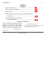
TM 5-3810-293-14&P-3, 6 June 1980, is changed as follows:
1. The title of the manual is changed to read as shown above.
2. Remove old pages and insert new pages.
3. New or changed material is indicated by a vertical bar in the margin of the page.
Remove Pages
i and ii
Page 53 and Page 54
Insert Pages
i /(ii blank)
Page 53 and 54
4. File this change sheet in front of the publication for reference purposes.
Approved for public release; distribution is unlimited.
TM 5-3810-293-14&P-3
C2
Changes in force: C 1 and C 2
CHANGE
HEADQUARTERS
DEPARTMENT OF THE ARMY
Washington D.C., 12 July 1991
NO. 2
OPERATOR'S, ORGANIZATIONAL, DIRECT SUPPORT,
GENERAL SUPPORT, AND DEPOT MAINTENANCE MANUAL
(INCLUDING REPAIR PARTS INFORMATION AND SUPPLEMENTAL
MAINTENANCE INSTRUCTIONS)
FOR
CRANE, TRUCK MOUNTED, HYDRAULIC, 25 TON (CCE)
HARNISCHFEGER MODEL MT-250, NON-WINTERIZED
NSN 3810-00-018-2021
HARNISCHFEGER MODEL MT-250, WINTERIZED
NSN 3810-00-018-2007
TM 5-3810-293-14&P-3, 6 June 1980, is changed as
follows:
Add the NBC exposure WARNING on each of the
following pages:
Page 5. The following paragraph is added at the
beginning
of
the
page
below
"GENERAL
DESCRIPTION":
On page 17, preceding the paragraph "Air Cleaners"; on
page 114 below "Air Inlet Restriction"; on page 117 in
the section entitled "TEMPORARY STORAGE (30 days
of less)", preceding paragraph 4; on page 118,
preceding paragraph 14; on page 119, preceding
paragraph 11; in that portion of the book entitled
"SERIES 53, SERVICE MANUAL, DETROIT DIESEL
ENGINES", in Section 3, at Sec. 3.1, page 1, under
"AIR CLEANER"; at Sec. 15.1,page 5, in Item 10; at
Sec 15.2, page 9, preceding paragraph 8; at Sec. 15.3,
page 1, under "TEMPORARY STORAGE (30 days or
less)", preceding paragraph 4; and at Sec. 15.3, page 3,
under "PROCEDURE FOR RESTORING AN ENGINE
TO SERVICE WHICH HAS BEEN IN EXTENDED
STORAGE", preceding paragraph 11:
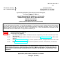
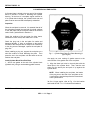
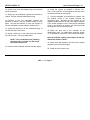
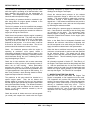
A decal has been developed that warns of NBC
exposure. It is to be positioned in a noticeable place on
or near the air cleaner or air filter housing. You may
order the decal using part number 12296626, CAGEC
19207. Refer to TB 43-0219 for further information.
Add the decal to the air cleaner tray (Figure 9 and
Figure 10), the United Specialties Dry Type Air Cleaner
body (Figure 11), and the Farr Dry Type Air Cleaner
housing (Figure 12).
WARNING
If NBC exposure is suspected, all air
filter media should be handled by
personnel
wearing
protective
equipment. Consult your unit NBC
Officer or NBC NCO for appropriate
handling or disposal Instructions.
Figure 1.1 - NBC Warning Decal
By Order of the Secretary of the Army:
GORDON R. SULLIVAN
General, United States Army
Chief of Staff
Official:
PATRICIA P. HICKERSON
Brigadier General, United States Army
The Adjutant General
Distribution:
To be distributed IAW DA Form 12-25-E (Block No. 0571) Operator, Unit, Direct Support and General Support
maintenance requirements for TM 5-3810-293-14&P-3.
TM 5-3810-293-14&P-3
CHANGE
NO.1
HEADQUARTERS
DEPARTMENT OF THE ARMY
Washington, D.C., 10 October, 1986
OPERATOR'S, ORGANIZATIONAL, DIRECT SUPPORT,
GENERAL SUPPORT, AND DEPOT MAINTENANCE MANUAL
(INCLUDING REPAIR PARTS INFORMATION AND SUPPLEMENTAL
MAINTENANCE INSTRUCTIONS)
FOR
CRANE, TRUCK MOUNTED, HYDRAULIC, 25 TON (CCE)
HARNISCHFEGER MODEL MT-250, NON-WINTERIZED
NSN 3810-00-018-2021
HARNISCHFEGER MODEL MT-250, WINTERIZED
NSN 3810-00-018-2007
TM 5-3810-293-14&P-3, 6 June 1980, is changed as follows:
1. Part Three-Engine Parts Catalog in this manual is replaced by TM5-3810-293-20P, ORGANIZATIONAL
MAINTENANCE REPAIR PARTS AND SPECIAL TOOLS LISTS, and TM5-3810-293-34P, DIRECT SUPPORT
AND GENERAL SUPPORT MAINTENANCE REPAIR PARTS AND SPECIAL TOOLS LISTS.
File this change sheet in front of the publication for reference purposes.
By Order of the Secretary of the Army:
Official:
JOHN A. WICKHAM, JR
General, United States Army
Chief of Staff
R.L. DILWORTH
Brigadier General, United States Army
The Adjutant General
Distribution:
To be distributed in accordance with DA Form 12-25A-R, Operator, Organizational, Direct Support and General
Support Maintenance requirements for Cranes, Truck Mounted, Hydraulic, 25-T, Model MT-250.
TM 5-3810-293-14&P-3
C3
TECHNICAL MANUAL
No. 5-3810-293-14&P-3
}
HEADQUARTERS
DEPARTMENT OF THE ARMY
Washington D.C., 6 June 1980
Operator Organizational, Direct Support, General Support,
and Depot Maintenance Manual
for
CRANE, TRUCK MOUNTED, HYDRAULIC, 25-TON (CCE),
HARNISCHFEGER MODEL MT-250, NON-WINTERIZED
(NSN 3810-00-018-2021)
(NSN 3810-00-018-2007)
HANISHCHFEGER MODEL MT-250, WINTERIZED
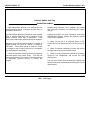
REPORTING ERRORS AND RECOMMENDING IMPROVEMENTS
You can help improve this manual. If you find any mistakes or if you know of a way to improve the procedures, please
let us know. Mail your letter, DA Form 2028 (Recommended Changes to Publications and Blank Forms), or DA Form
2028-2, located in the back of this manual, direct to: Commander, U.S. Army Tank-Automotive Command, ATTN:
AMSTA-MB, Warren, MI 48397-5000. A reply will be furnished to you.
Part One.
ENGINE OPERATOR'S MANUAL........................................................................................
Part Two
ENGINE SERVICE MANUAL
NOTE:
Part Three, ENGINE PARTS CATALOG, has been replaced by TM 5-381 0-293-20P and TM 53810-293-34P.
NOTE:
Part Three, ENGINE PARTS CATALOG, has been replaced by TM 5-3810-293-20P and TM 5-3810293-34P.
NOTE:
Refer to TM 5-3810-293-14&P-1 for Crane Operator's Manual, Weighload Automatic Safe Load
Indicator.
NOTE:
Refer to TM 5-3810-293-14&P-2 for Crane Shop Manual, Front Axle, Transmissions, and Winches.
This technical manual is an authentication of the manufacturers' commercial literature and does not
conform with the format and content specified on AR 310-3, Military Publications. This technical manual
does, however, contain available Information that is essential to the operation and maintenance of the
equipment.
Approved for public release; distribution is unlimited.
Change 3 i/(ii blank)
PART ONE
ENGINE OPERATOR'S MANUAL
6SE337 (Rev. 9/74)
TO THE OPERATOR
This manual contains instructions on the operation and preventive maintenance of your
Detroit Diesel engine.
Sufficient descriptive material, together with numerous
illustrations, is included to enable the operator to understand the basic construction of
the engine and the principles by which it functions. This manual does not cover engine
repair or overhaul.
Whenever possible, it will pay to rely on an authorized Detroit Diesel Allison Service
Outlet for all your service needs from maintenance to major parts replacement. There
are over 1500 authorized service outlets in the U.S. and Canada. They stock factory
original parts and have the specialized equipment and personnel with technical
knowledge to provide skilled and efficient workmanship.
The operator should familiarize himself thoroughly with the contents of the manual
before running an engine, making adjustments, or carrying out maintenance procedures.
The information, specifications and illustrations in this publication are based on the
information in effect at the time of approval for printing. Generally, this publication is
reprinted annually. It is recommended that users contact an authorized Detroit Diesel
Allison Service Outlet for information on the latest revision. The right is reserved to
make changes at any time without obligation.
WARRANTY
The applicable engine warranty is contained in the form entitled POLICY ON OWNER
SERVICE, available from authorized Detroit Diesel Allison Service Outlets.
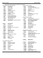
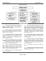
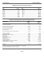
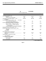
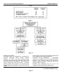
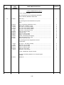
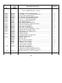
TABLE OF CONTENTS
SUBJECT
PAGE
DESCRIPTION
Principles of Operation.........................................................................................................................................4
General Description .............................................................................................................................................5
Model Description ................................................................................................................................................6
General Specifications .........................................................................................................................................8
Engine Model and Serial Number Designation .....................................................................................................9
Built-In Parts Book ...............................................................................................................................................9
Cross Section Views of Engine........................................................................................................................... 10
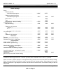
ENGINE SYSTEMS
Fuel System....................................................................................................................................................... 13
Air System ......................................................................................................................................................... 17
Lubricating System............................................................................................................................................. 22
Cooling System.................................................................................................................................................. 25
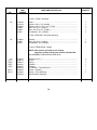
ENGINE EQUIPMENT
Instrument Panel, Instruments and Controls ....................................................................................................... 31
Engine Protective Systems ................................................................................................................................ 33
Electrical Starting System .................................................................................................................................. 37
Hydraulic Starting System .................................................................................................................................. 38
Cold Weather Starting Aids ................................................................................................................................ 41
Governors .......................................................................................................................................................... 44
Transmissions .................................................................................................................................................... 44
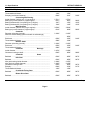
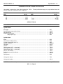
OPERATING INSTRUCTIONS
Engine Operating Instructions ............................................................................................................................ 47
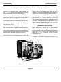
A.C. Power Generator Set Operating Instructions.............................................................................................. 51
LUBRICATION AND PREVENTIVE MAINTENANCE
Lubrication and Preventive Maintenance............................................................................................................ 55
Fuel, Lubricants and Coolants ............................................................................................................................ 66
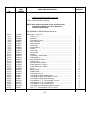
ENGINE TUNE-UP PROCEDURES
Engine Tune-Up Procedures .............................................................................................................................. 73
Exhaust Valve Clearance Adjustment ................................................................................................................ 74
Timing Fuel Injector ........................................................................................................................................... 76
Limiting Speed Mechanical Governor (In-Line Engines) ..................................................................................... 77
Limiting Speed Mechanical Governor (6V-53 Engine) ........................................................................................ 82
Variable Speed Mechanical Governor (In-Line Open Linkage) ........................................................................... 87
Variable Speed Mechanical Governor (In-Line Enclosed Linkage)...................................................................... 91
Variable Speed Mechanical Governor (6V-53 Engine)........................................................................................ 96
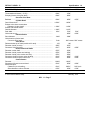
Supplementary Governing Device Adjustment ................................................................................................ 101
Hydraulic Governor (In-Line Engine) ................................................................................................................ 106
Hydraulic Governor (6V-53 Engine).................................................................................................................. 109
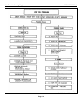
TROUBLE SHOOTING ................................................................................................................................... 111
STORAGE ....................................................................................................................................................... 117
BUILT-IN PARTS BOOK ................................................................................................................................. 121
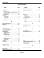
ALPHABETICAL INDEX.................................................................................................................................. 145
DETROIT DIESEL
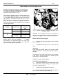
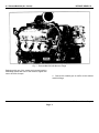
DESCRIPTION
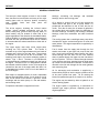
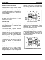
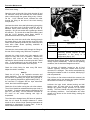
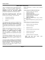
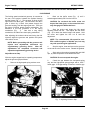
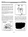
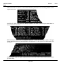
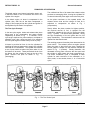
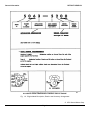
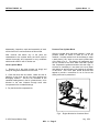
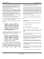
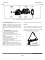
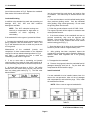
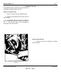
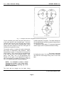
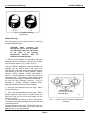
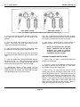
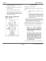
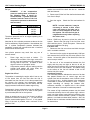
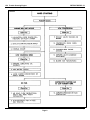
PRINCIPLES OF OPERATION
The unidirectional flow of air toward the exhaust valves
produces a scavenging effect, leaving the cylinders
full of clean air when the piston again covers the inlet
ports.
The diesel engine is an internal combustion power unit,
in which the heat of fuel is converted into work in the
cylinder of the engine.
In the diesel engine, air alone is compressed in the
cylinder; then, after the air has been compressed, a
charge of fuel is sprayed into the cylinder and ignition is
accomplished by the heat of compression.
As the piston continues on the upward stroke, the
exhaust valves close and the charge of fresh air is
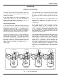
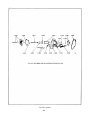
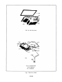
subjected to compression as shown in Fig. 1
(compression).
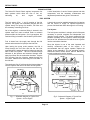
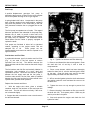
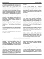
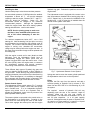
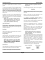
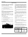
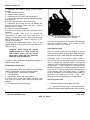
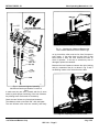
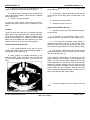
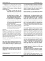
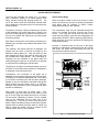
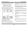
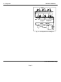
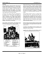
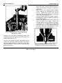
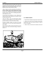
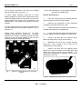
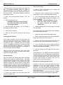
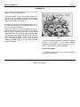
The Two-Cycle Principle
Shortly before the piston reaches its highest position,
the required amount of fuel is sprayed
into the
combustion chamber by the unit fuel injector as shown
in Fig. 1 (power). The intense heat generated during
the high compression of the air ignites the fine fuel
spray immediately. The combustion continues until the
injected fuel has been burned.
In the two-cycle engine, intake and exhaust take place
during part of the compression and power strokes
respectively, as shown in Fig. 1. In contrast, a fourcycle engine requires four piston strokes to complete an
operating cycle; thus, during one half of its operation,
the four-cycle engine functions merely as an air pump.
The resulting pressure forces the piston downward on its
power stroke. The exhaust valves are again opened
when the piston is about halfway down, allowing the
burned gases to escape into the exhaust manifold as
shown in Fig. 1 (exhaust). Shortly thereafter, the
downward moving piston uncovers the inlet ports and
the cylinder is again swept with clean scavenging air.
This entire combustion cycle is completed in each
cylinder for each revolution of the crankshaft, or, in
other words, in two strokes; hence, it is a "two-stroke
cycle".
A blower is provided to force air into the cylinders for
expelling the exhaust gases and to supply the cylinders
with fresh air for combustion. The cylinder wall contains
a row of ports which are above the piston when it is at
the bottom of its stroke. These ports admit the air from
the blower into the cylinder as soon as the rim of the
piston uncovers the ports as shown in Fig.
1
(scavenging).
Fig. 1 - The Two-Stroke Cycle
Page 4
DETROIT
DIESEL
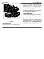
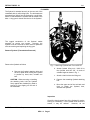
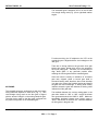
GENERAL DESCRIPTION
bearings, connecting rod bearings, and camshaft
bearings, and to other moving parts.
The two-cycle diesel engines covered in this manual
have the same bore and stroke and many of the major
working parts such as injectors, pistons, connecting
rods,
cylinder
liners
and
other
parts
are
interchangeable.
Oil is drawn by suction from the oil pan through the
intake screen and pipe to the oil pump where it is
pressurized and delivered to the oil filter and the oil
cooler. From the oil cooler, the oil enters oil galleries in
the cylinder block and cylinder head for distribution to
the main bearings, connecting rod bearings, camshaft
bearings, rocker arm mechanism and other functional
parts.
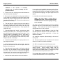
The In-line engines, including the inclined marine
models, include standard accessories such as the
blower, water pump, governor and fuel pump, which, on
some models, may be located of either side of the
engine regardless of the direction the crankshaft rotates.
Further flexibility in meeting installation requirements is
achieved with the cylinder head which can be installed
to accommodate the exhaust manifold on either side of
the engine.
The cooling system has a centrifugal water pump which
circulates the engine coolant through the oil cooler and
water jackets. The engine temperature is regulated by a
thermostat(s).
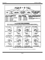
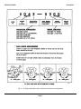
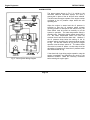
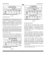
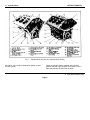
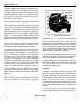
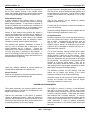
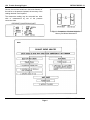
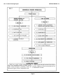
The V-type engine uses many In-line engine parts,
including the 3-53 cylinder head.
The blower is
mounted on top of the engine between the two banks of
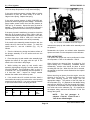
cylinders and is driven by the gear train. The governor
is mounted on the rear end of the 6V-53 blower, The
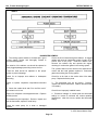
meaning-f each digit in the model numbering system is
shown i Figs. 2 and 3. The letter L or R indicates left
or right-hand engine rotation as viewed from the front of
the engine. The letter A,B,C or D designates the blower
and exhaust manifold location on the In-line engines as
viewed from the rear of the engine while the letter A or
C designates the location of the oil cool-t and starter on
the 6V-53 engine.
Fuel is drawn from the supply tank through the fuel
strainer and enters a gear type fuel pump at the inlet
side. Upon leaving the pump under pressure, the fuel is
forced through the fuel filter into the inlet manifold
where it passes through fuel pipes into the inlet side of
the fuel injectors. The fuel is filtered through elements
in the injectors and then atomized through small spray
tip orifices into the combustion chamber. Excess fuel is
returned to the fuel tank through the fuel outlet galleries
and connecting lines.
Air for scavenging and combustion is supplied by a
blower which pumps air into the engine cylinders via the
air box and cylinder liner ports. All air entering the
blower first passes through an air cleaner or air silencer.
Each engine is equipped with an oil cooler, replaceable
element type lubricating oil filter, fuel oil strainer, fuel oil
filter, an air cleaner or air silencer, a governor, a heat
exchanger and raw water pump or a fan and radiator,
and a starting motor.
The engine may be started by either a hydraulic or an
electric starting system.
The engine speed is regulated by a mechanical or
hydraulic type engine governor, depending upon the
engine application.
Full pressure lubrication is supplied to all main
Page 5
Description
DETROIT DIESEL
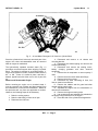
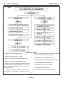
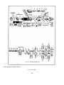
Fig. 2 - In-Line Engine Model Description, Rotation and Accessory Arrangement
Page 6
DETROIT DIESEL
Description
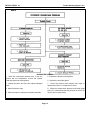
Fig. 3 - 6V Engine Model Description, Rotation and Accessory Arrangement
Page 7
Description
DETROIT DIESEL
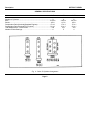
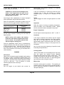
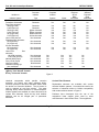
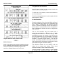
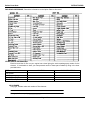
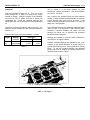
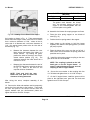
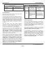
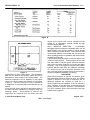
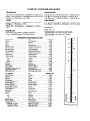
GENERAL SPECIFICATIONS
3-53
Number of Cylinders .............................................................................. 3
Bore .................................................................................................. 3.875 in
Stroke ................................................................................................. 4.5 in
Compression Ratio (Nominal)(Standard Engines)............................... 17 to 1
Compression Ratio (Nominal)("N" Engines)........................................ 21 to 1
Total Displacement - Cubic Inches ....................................................... 159
Number of Main Bearings....................................................................... 4
Fig. 4 - Series 53 Cylinder Arrangement
Page 8
4-53
6V-53
4
3.875 in
4.5 in
17 to 1
21 to 1
212
5
6
3.875 in.
4.5 in.
17 to 1
21 to 1
318
4
DETROIT DIESEL
Description
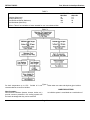
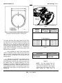
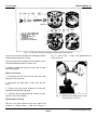
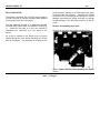
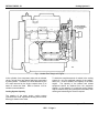
ENGINE MODEL AND SERIAL NUMBER DESIGNATION
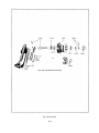
Fig. 5 Typical Model and Serial Numbers as Stamped
on Cylinder Block (In-Line Engine)
Fig. 6 Typical Model and Serial Numbers as Stamped
on Cylinder Block (6V Engine)
On the In-line engines, the model number and serial
number are stamped on the right-hand side of the
cylinder block in the upper rear corner (Fig. 5). The
model number and serial number on the V-type engine
is located on the top right-hand front corner of the
cylinder block, as viewed from the rear of the engine
(Fig. 6).
Power take-off assemblies, torque converters, hydraulic
marine gears, etc.
may also carry name plates
pertaining to the particular assembly to which they are
attached. The information on these name plates is
useful when ordering Darts for these assemblies.
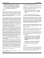
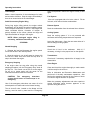
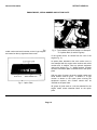
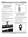
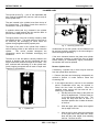
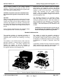
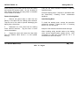
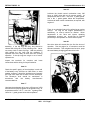
An option plate, attached to the valve rocker cover, is
also stamped with the engine serial number and model
number and, in addition, lists any optional equipment
used on the engine (Fig. 7).
With any order for parts, the engine model number and
serial number must be given. In addition, if a type
number is shown on the option plate covering the
equipment required, this number should also be
included on the parts order.
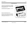
Fig. 7 - Option Plate
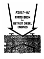
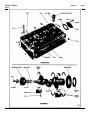
BUILT - IN PARTS BOOK
The Built-In Parts Book is an anodized aluminum plate
(Option Plate) that fits into a retainer on the engine
valve rocker cover and contains the necessary
information required when ordering parts.
It is
recommended that the engine user read the section or
the Built-In Parts Book in order to take full advantage of
the information provided on the engine option
plate.
Numerous exploded view type illustrations are included
to assist the user in identifying and ordering service
parts.
Page 9
DESCRIPTION
DETROIT DIESEL
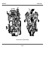
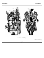
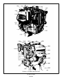
Cross Section Views of a Typical In-Line Engine
Page 10
DESCRIPTION
DETROIT DIESEL
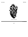
Cross Section Views of a Typical 6V-53 Engine
Page 11
DETROIT DIESEL
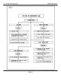
ENGINE SYSTEMS
The Series 53 Detroit Diesel engines incorporate four
A brief description of each of these systems and their
basic systems which direct the flow of fuel, air,
components, and the necessary maintenance and
lubricating
oil,
and
engine
coolant.
adjustment procedures are given in this manual.
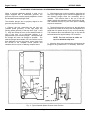
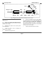
FUEL SYSTEM
The fuel system (Figs. 1 and 2) consists of the fuel
injectors, fuel pipes, fuel manifolds (integral with the
cylinder head), fuel pump, fuel strainer, fuel filter and
the necessary connecting fuel lines.
A check valve may be installed between the fuel strainer
and the source of supply as optional equipment to
prevent fuel drain back when the engine is not running.
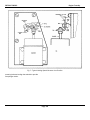
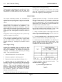
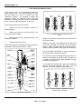
Fuel Injector
On In-line engines, a restricted fitting is located in the
cylinder head fuel return manifold outlet to maintain
pressure within the fuel system. On V-type engines, this
restricted fitting is located in the left-bank cylinder head.
Fuel is drawn from the supply tank through the fuel
strainer and enters the fuel pump at the inlet side.
Upon leaving the pump under pressure, the fuel is
forced through the fuel filter and into the fuel inlet
manifold where it passes through fuel pipes into the inlet
side of each fuel injector. The fuel is filtered through
elements in the injectors and atomized through small
spray tip orifices into the combustion chamber. Surplus
fuel, returning from the injectors, passes through the
fuel return manifold and connecting fuel lines back to
the fuel tank.
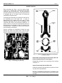
The fuel injector combines in a single unit all of the parts
necessary to provide complete and independent fuel
injection at each cylinder. The injector creates the high
pressure necessary for fuel injection, meters the proper
amount of fuel, atomizes the fuel and times the injection
into the combustion chamber.
Since the injector is one of the most important and
carefully constructed parts of the engine, it is
recommended that the engine operator replace the
injector as an assembly if it is not operating properly.
Authorized Detroit Diesel Allison Service Outlets are
properly equipped to service injectors.
The continuous flow of fuel through the injectors helps to
cool the injectors and remove air from the fuel system.
Fig. 1 - Schematic Diagram of Typical Fuel
System - In-Line Engine
Fig 2 - Schematic Diagram of Typical Fuel
System - V-type Engine
Page 13
Engine Systems
DETROIT DIESEL
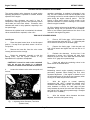
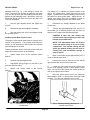
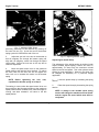
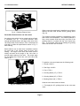
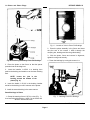
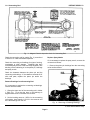
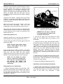
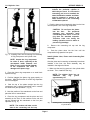
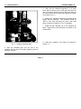
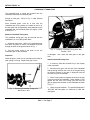
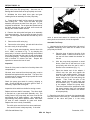
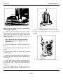
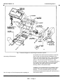
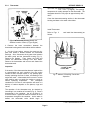
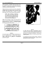
8. Free the injector from its seat as shown in Fig. 3 and
lift it from the cylinder head.
9. Cover the injector hole in the cylinder head to keep
foreign particles out of the cylinder.
Install Injector
Before installing an injector, be sure the beveled seat of
the injector tube is free from dirt particles and carbon
deposits.
A new or reconditioned injector may be installed by
reversing the sequence of operations given above for
removal.
Be sure the injector is filled with fuel oil. If necessary,
add clean fuel oil at the inlet filter until it runs out the
outlet filter.
CAUTION: On four valve cylinder
heads, there is a possibility of
damaging the exhaust valves if the
exhaust valve bridge is not resting
on the ends of the exhaust valves
when tightening the rocker shaft
bracket bolts. Therefore, note the
position of the exhaust valve bridge
before, during and after tightening
the rocker shaft bracket bolts.
Fig. 3 - Removing Injector from Cylinder Head
Remove Injector
An injector may be removed in the following manner:
1. Clean and remove the valve rocker cover.
2. Disconnect the fuel pipes from both the injector and
the fuel connectors.
3. Immediately after removing the fuel pipes, cover the
injector inlet and outlet fittings with shipping caps to
prevent dirt from entering.
4. Turn the crankshaft manually in the direction of
engine rotation or crank the engine with the starting
motor, if necessary, until the rocker arms for the
particular cylinder are aligned in a horizontal plane.
CAUTION: If a wrench is used on the
crankshaft bolt at the front of the engine,
do not turn the crankshaft in a left-hand
direction of rotation as the bolt will be
loosened. Remove the starting motor
and use a pry bar against the teeth of the
flywheel ring gear to turn the crankshaft.
5. Remove the two rocker shaft bracket bolts and swing
the rocker arm assembly away from the injector and
valves.
6. Remove the injector clamp bolt, washer and clamp.
Do not tighten the injector clamp bolt to more than 20-25
lb.-ft torque, as this may cause the moving parts of the
injector Jo bind. Tighten the rocker shaft bolts to 50-55
lb.-ft torque.
Align the fuel pipes and connect them to the injector and
the fuel connectors. Us socket J 8932-01 and a torque
wrench to tighten the fuel pipe nuts to 12-15 lb. ft
torque.
CAUTION: o not bend the fuel pipes
and do not exceed the specified
torque.
Excessive tightening will
twist or fracture the flared ends of
the fuel pipes and result in leaks.
Lubricating oil diluted by fuel oil can
cause serious damage to the engine
bearings.
Time the injector, position the injector rack control lever
and adjust the exhaust valve clearance (cold setting) as
outlined in the engine tune-up procedure. If all of the
injectors have been replaced, perform a complete tuneup on the engine
7. Loosen the inner and outer adjusting screws on the
injector rack control lever and slide the lever away from
the injector.
Page 14
DETROIT DIESEL
Engine Systems
Fuel Pump
A positive displacement gear-type fuel pump is
attached to the governor or blower on the In-line engines
and to the flywheel housing on the V-type engines.
A spring-loaded relief valve. incorporated in the pump
body, normally remains In the closed position, operating
only when the pressure on the outlet side (to the fuel
filter) becomes excessive due to a plugged filter or fuel
line.
The fuel pump incorporates two oil seals. Two tapped
holes are provided in the underside of the pump body,
between the oil seals, to permit a drain tube to be
attached. If fuel leakage exceeds one drop per minute,
the seals must be replaced. An authorized Detroit
Diesel Allison Service Outlet is properly equipped to
replace the seals.
Fuel pumps are furnished in either left or right-hand
rotation, according to the engine model, and are
stamped RH or LH.
These pumps are not
interchangeable and cannot be rebuilt to operate in an
opposite rotation.
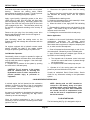
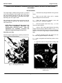
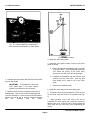
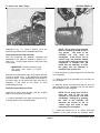
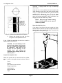
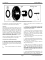
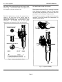
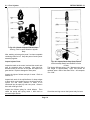
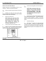
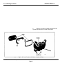
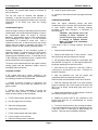
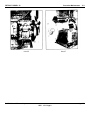
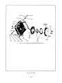
Fuel Strainer and Fuel Filter
A replaceable-element type fuel strainer and fuel filter
(Fig. 4) are used in the fuel system to remove
impurities from the fuel. The strainer removes the
larger particles and the filter removes the small foreign
particles.
The fuel strainer and fuel filter are basically identical in
construction, both consisting of a cover, shell and
replaceable element. Since the fuel strainer is placed
between the fuel supply tank and the fuel pump, it
functions under suction; the fuel filter, which is installed
between the fuel pump and the fuel inlet manifold in the
cylinder head, operates under pressure.
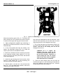
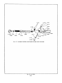
Fig. 4 - Typical Fuel Strainer and Filter Mounting
3. Remove and discard the element and gasket. Clean
the shell with fuel oil and dry it with a cloth or
compressed air.
4. Place a new element, which has been thoroughly
soaked in clean fuel oil, over the stud and push it down
on the seat. Close the drain cock and fill the shell
approximately two-thirds full with clean fuel oil.
5. Affix a new shell gasket, place the shell and element
into position under the cover and start the cover nut on
the shell stud.
Replace the elements as follows:
1.
With the engine shut down, place a suitable
container under the fuel strainer or filter and open the
drain cock. The fuel will drain more freely if the cover
nut is loosened slightly.
2. Support the shell, unscrew the cover nut and remove
the shell and element.
6. Tighten the cover nut only enough to prevent fuel
leakage.
7. Remove the plug in the strainer or filter cover and fill
the shell with fuel. Fuel system primer J 5956 may be
used to prime the fuel system.
8. Start and operate the engine and check the fuel
system for leaks.
Page 15
Engine Systems
DETROIT DIESEL
Spin-On Type Fuel Filter
A spin-on fuel strainer and fuel filter is used on certain
engines. The spin-on filter cartridge consists of a shell,
element and gasket combined into a unitized
replacement assembly. No separate springs or seats
are required to support the filters.
The filter covers incorporate a threaded sleeve to accept
the spin-on filter cartridges. The word "Primary" is cast
on the fuel strainer cover and the word "Secondary" is
cast on the fuel filter cover for identification.
No drain cocks are provided on the spin-on filters.
Where water is a problem, it is recommended that a
water separator be installed. Otherwise, residue may be
drained by removing and inverting the filter. Refill the
filter with clean fuel oil before reinstalling it.
2. Fill a new filter replacement cartridge about two
thirds full with clean fuel oil. Coat the seal gasket lightly
with clean fuel oil.
3. Install the new filter assembly and tighten it to two
thirds of a turn beyond gasket contact.
4. Start the engine and check for leaks.
Fuel Tank
Refill the fuel tank at the end of each day's operation to
prevent condensation from contaminating the fuel.
A 1 "diameter twelve-point nut on the bottom of the filter
is provided to facilitate removal and installation.
Replace the filter as follows:
1. Unscrew the filter (or strainer) and discard it.
Page 16
CAUTION:A galvanized steel tank
should never be used for fuel storage
because the fuel oil reacts chemically
with the zinc coating to form powdery
flakes which quickly clog the fuel
strainer and filter and damage the fuel
pump and the fuel injectors.
DETROIT DIESEL
Engine Systems
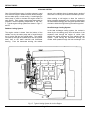
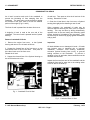
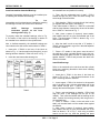
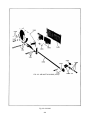
AIR SYSTEM
In the scavenging system used in two-cycle engines,
illustrated in Figs. 5 and 6, a charge of air is forced into
the cylinders by the blower and thoroughly sweeps out
all of the burned gases through the exhaust valve ports.
This air also helps to cool the internal engine parts,
particularly the exhaust valves. At the beginning of the
compression stroke, each cylinder is filled with fresh,
clean air which provides for efficient combustion.
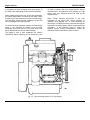
The air, entering the blower from the air silencer or air
cleaner, is picked up by the blower rotor lobes and
carried to the discharge side of the blower. The
continuous discharge of fresh air from the blower enters
the air chamber of the cylinder block and sweeps
through the intake ports of the cylinder liners.
The angle of the ports in the cylinder liner creates a
uniform swirling motion to the intake air as it enters the
cylinder.
This motion persists throughout the
compression stroke and facilitates scavenging and
combustion.
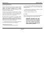
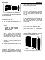
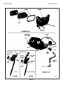
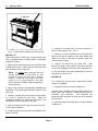
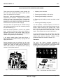
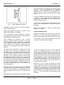
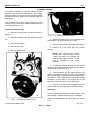
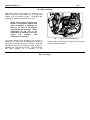
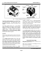
Air Cleaners
Several types of air cleaners are available for use with
industrial engines. The light-duty oil bath air cleaner is
used on most models. However, a heavy-duty oil bath
type or a dry type air cleaner may be installed where the
engine is operating in heavy dust concentrations.
The air cleaners are designed for fast, easy disassembly
to facilitate efficient servicing. Maximum protection of
the engine against dust and other forms of air
contamination is possible if the air cleaner is serviced at
regular intervals.
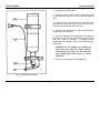
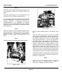
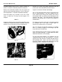
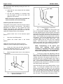
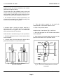
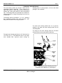
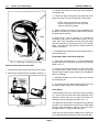
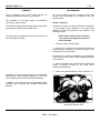
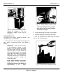
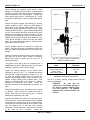
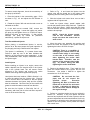
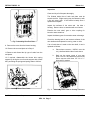
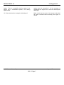
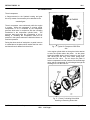
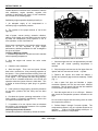
The light-duty oil bath type air cleaner (Fig. 7) consists
of a metal wool cleaning element supported inside of a
housing which contains an oil reservoir. A chamber
beneath, the oil reservoir serves as a silencer for the
incoming air to the blower. Air is drawn into the cleaner
by the blower and passes over the top of the oil bath,
where a major portion of the dirt is trapped, then up
through the metal wool, where the finer particles are
removed, and then down the central duct to the blower.
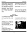
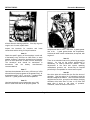
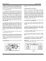
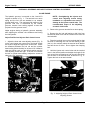
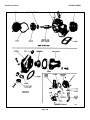
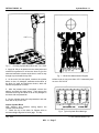
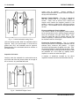
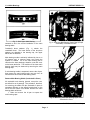
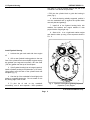
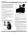
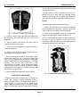
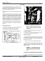
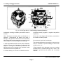
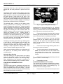
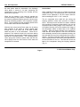
The heavy-duty oil bath type air cleaner (Fig. 8)
consists of the body and fixed filter assembly which
filters the air and condenses the oil from the air stream
so that only dry air enters the engine. The condensed
oil is returned to the cup where the dirt settles out of the
oil and the oil is recirculated. A removable element
assembly removes a major part of the dust from the air
stream thereby decreasing the dust load to the fixed
element. An inner cup, which can be removed from the
outer (oil cup), acts as a baffle in directing the oil-laden
air to the element and also controls the amount of oil in
circulation and meters the oil to the element. The oil
cup supports the inner cup and is a reservoir for oil and
a settling chamber for dirt.
Service the light-duty oil bath air cleaner as follows
Fig. 5 - Air Intake System Through Blower and
Engine (In-line Engine)
Fig. 6 · Air Intake System Through Blower and
Engine (6V-53 Engine)
Page 17
Engine Systems
DETROIT DIESEL
Tighten the wing bolt until the air cleaner is securely
mounted.
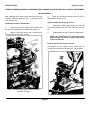
Service the heavy-duty oil bath air cleaner as follows:
1. Loosen the wing nuts and detach the lower portion of
the air cleaner assembly.
2. Remove the detachable screen by loosening the
wing nuts and rotating the screen one-quarter turn.
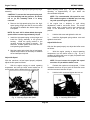
Fig. 7 Light-Duty Oil Bath Air Cleaner
1. Loosen the wing bolt and remove the air cleaner
assembly from the air inlet housing. The cleaner may
then be separated into two sections; the upper section or
body assembly contains the filter element, the lower
section consists of the oil cup, removable inner cup or
baffle and the center tube.
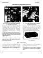
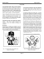
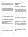
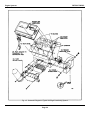
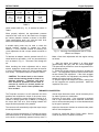
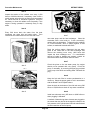
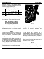
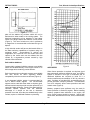
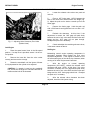
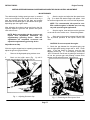
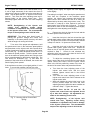
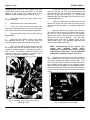
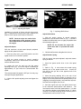
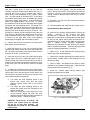
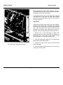
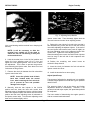
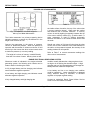
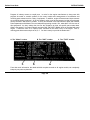
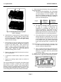
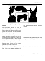
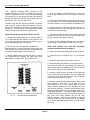
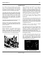
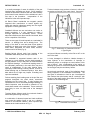
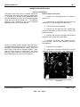
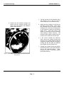
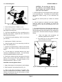
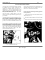
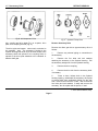
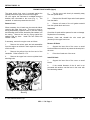
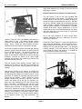
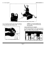
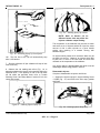
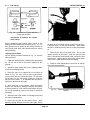
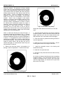
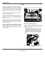
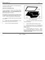
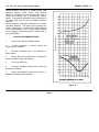
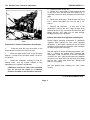
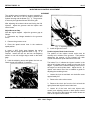
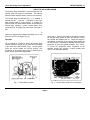
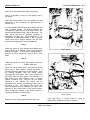
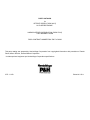
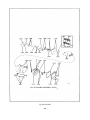
One of the most important steps in properly cleaning the
tray type oil bath air cleaner is a step that is most
overlooked. Unless the filter tray is thoroughly cleaned,
satisfactory performance of the engine cannot be
realized. The presence of fibrous material found in the
air is often underestimated and is the main cause of the
malfunctioning of heavy-duty air cleaners. This material
comes from plants and trees during their budding
season and later from airborne seed from the same
sources. Figure 9 illustrates the severity of plugging in a
tray that is 50% plugged. The solid black areas in the
mesh are accumulations of this fibrous material. When
a tray is plugged in this manner, washing in a solvent or
similar washing solution will not clean it satisfactorily. It
must be blown out with high pressure air or steam to
remove the material that accumulates between the
layers of screening. When a clean tray is held up to the
light, an even pattern of light should be visible.
2. Soak the body assembly and element in fuel oil to
loosen the dirt, then flush the element with clean fuel oil
and allow it to drain thoroughly.
3. Pour out the oil, separate the inner cup or baffle from
the oil cup. remove the sludge and wipe the baffle and
outer cup clean.
4. Push a lint-free cloth through the center tube to
remove dirt or oil.
5 Clean and check all of the gaskets and sealing
surfaces to ensure air tight seals.
6. Refill the oil cup to the oil level mark only, install the
baffle, and reassemble the air cleaner.
7. Check the air inlet housing before installing the air
cleaner assembly on the engine. The inlet will be dirty if
air cleaner servicing has been neglected or if dust-laden
air has been leaking past the air cleaner or air inlet
housing seals.
8. Make sure that the air cleaner is seated properly on
the inlet housing and the seal is installed correctly.
Fig. 8 - Heavy-Duty Oil Bath Air Cleaner
Page 18
DETROIT DIESEL
Engine Systems
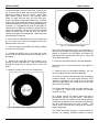
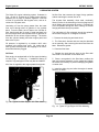
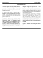
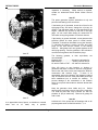
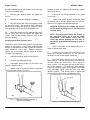
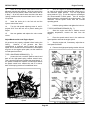
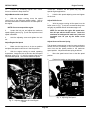
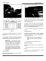
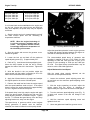
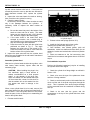
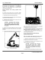
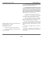
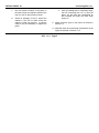
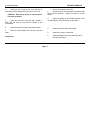
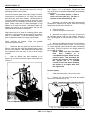
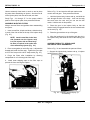
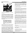
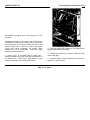
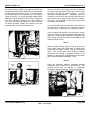
It may be necessary, only as a last resort, to burn off the
lint. Extreme care must be taken to prevent melting the
galvanized coating in the tray screens. Some trays
have equally spaced holes in the retaining baffle.
Check to make sure that they are clean and open.
Figure 10 illustrates a thoroughly cleaned tray. The dark
spots in the mesh indicate the close overlapping of the
mesh and emphasize the need for using compressed air
or steam. It is suggested that users of heavy-duty air
cleaners have a spare tray on hand to replace the tray
that requires cleaning. Having an extra tray available
makes for better service and the dirty tray can be
cleaned thoroughly as recommended. Spare trays are
well worth their investment.
3. Pour out the oil, separate the inner cup or baffle from
the oil or outer cup, remove the sludge and wipe the
baffle and outer cup clean.
4. Clean and inspect the gaskets and sealing surfaces
to ensure an air tight seal.
5. Reinstall the baffle in the oil cup and refill to the
proper oil level with the same grade of oil being used in
the engine.
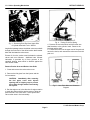
Fig. 10. Air Cleaner Tray (Clean)
and center tube each time the oil cup is serviced. If
there are any indications of plugging, the body assembly
should be removed from the engine and cleaned by
soaking and then flushing with clean fuel oil. Allow the
unit to drain thoroughly.
6. Remove the hood and clean by brushing, or by
blowing out with compressed air. Push a lint-free cloth
through the center tube to remove dirt or oil from the
walls.
8. Place the removable element in the body assembly.
7. Inspect the lower portion of the air cleaner body
9. Install the outer cup and baffle assembly. Be sure
the cup is tightly secured to the body assembly.
Install the body if it was removed from the engine for
servicing.
All oil bath air cleaners should be serviced as operating
conditions warrant. At no time should more than 1/2"of
"sludge" be allowed to form in the oil cup or the area
used for sludge deposit, nor should the oil cup be filled
above the oil level mark.
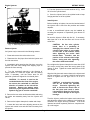
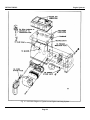
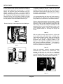
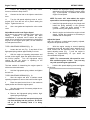
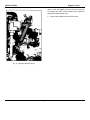
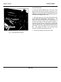
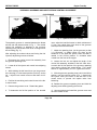
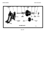
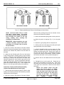
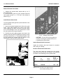
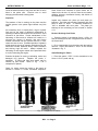
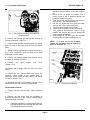
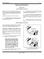
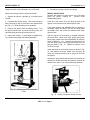
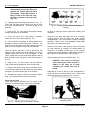
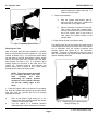
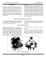
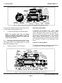
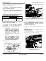
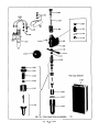
The United Specialties dry-type air cleaner shown in Fig.
11 consists of a body, dust unloader and element
clamped to a base.
Fig. 9. Air Cleaner Tray (Plugged) Engine Systems
Air is drawn through the cleaner intake pipe and is
automatically set into a circular motion. This positive
spinning of the dirty air "throws out" the heavier particles
of dust and dirt where they are collected in the dust port
and then expelled through the dust unloader. The
circular action continues even during low air intake at
engine idle speeds.
The United Specialties dry-type air cleaner should be
serviced, as operating conditions warrant as follows:
Page 19
Engine Systems
DETROIT DIESEL
Page 20 DETROIT DIESEL loosened foreign material
from the element. Shake out excess water from the
element and allow it to dry thoroughly.
CAUTION: Do not attempt to remove
excess water by using compressed
air.
Fig. 11 - United Specialties Dry Type Air Cleaner
1. Loosen the clamp screw and check the dust unloader
for obstruction or damage.
2. Unlock the spring clamps that hold the cleaner body
to the cleaner base which is bolted to the air inlet
housing. Remove the body and then remove the
element from the cleaner base.
3. The paper pleated air cleaner element can be
cleaned as follows:
a. For a temporary expedient in the field, tap the side
or end of the element carefully against the palm of
your hand.
4. Inspect the cleaned element with a light bulb after
each cleaning for damage or rupture. The slightest
break in t(e element will admit sufficient airborne dirt to
cause rapid failure of piston rings. If necessary, replace
the element.
5. Inspect the gasket on the end of the element. If the
gasket is damaged or missing, replace the element.
6. Install the element on the base with the gasket side
of the element down against the base. Place the body
over the element and base and tighten the spring
clamps by hand.
7. Replace the element after 10 washings or I year of
service, whichever comes first, or any time damage is
noted.
8. Install the dust unloader and tighten the clamp.
CAUTION: Do not tap the element
against a hard surface. This could
damage the element.
b. Compressed air can be used when the major
contaminant is dust. The compressed air (not to
exceed 100 psi) should be blown through the
element in a direction opposite to the normal air
flow. Insert the air nozzle inside of the element and
gently tap and blow out the dust with air. When
cleaning the dust from the outside of the element,
hold the nozzle at least 6" from the element.
c.
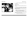
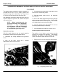
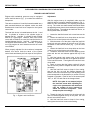
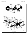
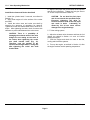
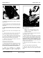
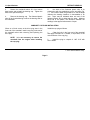
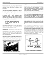
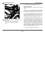
The Farr dry-type air cleaner (Fig. 12) is designed to
provide highly efficient air filtration under all operating
conditions and is not affected by engine speed. The
cleaner assembly consists of a cleaner panel with a
replaceable impregnated paper filter element.
The cleaner panel and replaceable filter element are
held together in a steel housing with fasteners.
Wash the element if compressed air is not
available, or when the contaminant is carbon, soot,
oily vapor or dirt which cannot be removed with
compressed air.
d. Agitate the element in warm water containing a nonsudsing detergent.
CAUTION: Do not use water hotter
than your hand can stand, solvents,
oil, fuel oil or gasoline.
Preceding the washing, it helps to direct air (not
exceeding 100 psi) through the element in a direction
opposite the normal air flow to dislodge as much dust as
possible. Reverse flush with a stream of water (not
exceeding 40 psi) until the water runs clean to rinse all
Page 20
Fig. 12 - Farr Dry Type Air Cleaner
DETROIT DIESEL
Engine Systems
The deflector vanes impart a swirling motion to the air
entering the air cleaner and centrifuge the dust particles
against the walls of the tubes. The dust particles are
then carried to the dust bin at the bottom of the cleaner
by approximately 10% bleed-off air and are finally
discharged into the atmosphere. The cleaner panel is
fully effective at either high or low velocities.
The remainder of the air in the cleaner reverses
direction and spirals back along the discharge tubes
again centrifuging the air. The filtered air then reverses
direction again and enters the replaceable filter element
through the center portion of the discharge tubes. The
air is filtered once more as it passes through the pleats
of the impregnated paper element before leaving the
outlet port of the cleaner housing.
The cleaner panel tends to be self-cleaning. However, it
should be inspected and any accumulated foreign
material removed during the periodic replacement of the
impregnated paper filter element. Overloading of the
paper element will not cause dirt particles to bypass the
filter and enter the engine, but will result in starving the
engine for air.
The filter element should be replaced, as operating
conditions warrant, as follows:
1. Loosen the wing nuts on the fasteners and swing the
retaining bolts away from the cleaner panel.
2. Lift the cleaner panel away from the housing and
inspect it. Clean out any accumulated foreign material.
3. Withdraw the paper filter element and discard it.
4. Install a new filter element.
5. Install the cleaner panel and secure it in place with
the fasteners.
Air Silencer
The air silencer, used on some marine engines, is bolted
to the intake side of the blower housing. The silencer
has a perforated steel partition welded in place parallel
with the outside faces, enclosing flameproof, felted
cotton waste which serves as a silencer for air entering
the blower.
While no servicing is required on the air silencer proper,
it may be removed when necessary to replace the air
inlet screen. This screen is used to filter out any Engine
Systems large foreign particles which might seriously
damage the blower assembly.
Air Box Drains
During normal engine operation, water vapor from the
air charge, as well as a slight amount of fuel and
lubricating oil fumes, condenses and settles on the
bottom of the air box. This condensation is removed by
the air box pressure through air box drain tubes
mounted on the side of the cylinder block.
The air box drains must be open at all times. With the
engine running, a periodic check is recommended for air
flow from the air box drain tubes. Liquid accumulation
on the bottom of the air box indicates a drain tube may
be plugged. Such accumulations can be seen by
removing the cylinder block air box cover(s) and should
be wiped out with rags or blown out with compressed air.
Then remove the drain tubes and connectors from the
cylinder block and clean them thoroughly.
Some engines are equipped with an air box drain check
valve.
Refer to the Lubrication and Preventive
Maintenance section of this manual for service
instructions.
Crankcase Ventilation
Harmful vapors which may form within the engine are
removed from the crankcase, gear train and valve
compartment by a continuous, pressurized ventilation
system.
A slight pressure is maintained within the engine
crankcase by the seepage of a small amount of air from
the airbox past the piston rings. This air sweeps up
through the engine and is drawn off through a crankcase
breather.
In-line engines are equipped with a breather assembly
which is mounted on the rocker cover or the flywheel
housing.
The 6V engines incorporate a breather
assembly mounted inside of the upper engine front
cover.
The wire mesh pad (element) in the breather assemblies
should be cleaned if excessive crankcase pressure is
observed. If it is necessary to clean the element,
remove the breather housing from the flywheel housing
(In-line engines) and the upper engine front cover (6V
engines). Wash the element in fuel oil and dry it with
compressed air. Reinstall the element and the breather
assembly.
Page 21
Engine Systems
DETROIT DIESEL
LUBRICATING SYSTEM
The Series 53 engine lubricating system, illustrated in
Figs. 15 and 16, includes an oil intake screen and tube
assembly, an oil pump, a pressure regulator, a full-flow
oil filter or by-pass filter with by-pass valve; and an oil
cooler with a by-pass valve.
Lubricating oil from the pump passes from the lower
front cover through short oil galleries in the cylinder
block. From the block, the oil flows to the full-flow oil
filter, then through the oil cooler (if used) and back into
the front engine cover and cylinder block oil galleries for
distribution to the various engine bearings. The drains
from the cylinder head(s) and other engine parts lead
back to the oil pan.
Oil pressure is regulated by a pressure relief valve
mounted in the engine front cover. Oil cooler and oil
filter by-pass valves prevent the stoppage of oil flow if
these items become plugged.
full-flow filter that removes the larger foreign particles
without restricting the normal flow of oil.
The by-pass filter assembly, when used, continually
filters a portion of the lubricating oil that is being bled off
the oil gallery when the engine is running. Eventually all
of the oil passes through the filter, filtering out minute
foreign particles that may be present.
The lubricating oil filter elements should be replaced,
each time the engine oil is changed, as follows:
1. Remove the drain plug and drain the oil.
2. The filter shell, element and stud may be detached
as an assembly, after removing the center stud from the
base. Discard the gasket.
3. Clean the filter base.
4. Discard the used element, wipe out the filter shell
and install a new element on the center stud.
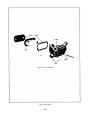
Oil Filters
Each engine is equipped with a full-flow type lubricating
oil filter (Figs. 13 and 14). If additional filtering is
required, a by-pass type oil filter may also be installed.
All of the oil supplied to the engine passes through the
5. Place a new gasket in the filter base, position the
shell and element assembly on the gasket and tighten
the center stud carefully to prevent damaging the gasket
or center stud.
6. Install the drain plug and, after the engine is started,
check for oil leaks.
Fig 13. Typical In-Line Engine Oil Filter Mounting
Fig. 14. Typical V-Type Engine Oil Filter Mounting
Page 22
DETROIT DIESEL
Engine Systems
Fig. 15. Schematic Diagram of Typical In-Line Engine Lubricating System
Page 23
Engine Systems
DETROIT DIESEL
Fig. 16. Schematic Diagram of Typical 6V Engine Lubricating System
Page 24
DETROIT DIESEL
Engine Systems
COOLING SYSTEM
One of three different types of cooling systems is used
on a Series 53 engine: radiator and fan, heat exchanger
and raw water pump, or keel cooling. A centrifugal type
water pump is used to circulate the engine coolant in
each system. Each system incorporates thermostats to
maintain a normal operating temperature of 160°-185°
F. Typical engine cooling systems are shown in Figs. 17
and 18.
returns to the radiator where it passes down a series of
tubes and is cooled by the air stream created by the fan.
When starting a cold engine or when the coolant is
below operating temperature, the coolant is restricted at
the thermostat housing(s) and a by-pass provides water
circulation within the engine during the warm-up period.
Heat Exchanger Cooling System
Radiator Cooling System
The engine coolant is drawn from the bottom of the
radiator core by the water pump and is forced through
the oil cooler and into the cylinder block. The coolant
circulates up through the cylinder block into the cylinder
head, then to the water manifold and thermostat
housing. From the thermostat housing, the coolant
In the heat exchanger cooling system, the coolant is
drawn by the circulating pump from the bottom of the
expansion tank through the engine oil cooler, then
through the engine the same as in the radiator and fan
system. Upon leaving the thermostat housing, the
coolant either passes through the heat exchanger core
Fig. 17. Typical Cooling System for In-Line Engine
Page 25
Engine Systems
DETROIT DIESEL
or by-passes the heat exchanger and flows directly to
the water pump, depending on the coolant temperature.
While passing through the core of the heat exchanger,
the coolant temperature is lowered by raw water, which
is drawn by the raw water pump from an outside supply.
The raw water enters the heat exchanger at one side
and is discharged at the opposite side.
To protect the heat exchanger element from electrolytic
action, a zinc electrode is located in both the heat
exchanger inlet elbow and the raw water pump inlet
elbow and extends into the raw water passage.
The length of time a heat exchanger will function
satisfactorily before cleaning will be governed by the
AS kind of coolant used in the engine and the kind of
raw water used. Soft water plus a rust inhibitor or a high
boiling point type antifreeze should be used as the
engine coolant.
When foreign deposits accumulate in the heat
exchanger to the extent that cooling efficiency is
impaired, such deposits can, in most instances, be
removed by circulating a flushing compound through the
fresh water circulating system without removing the heat
exchanger. If this treatment does not restore the
engine's normal cooling characteristics, contact an
authorized Detroit Diesel Allison Service Outlet.
Fig. 18. Typical Cooling System for V-Type Engine
Page 26
DETROIT DIESEL
Engine Systems
Keel Cooling System
The keel cooling system is similar to the heat exchanger
system, except that the coolant temperature is reduced
in the keel cooler. In this system, the coolant is drawn
by the circulating pump from the bottom of the
expansion tank through the engine oil cooler. From the
cooler the flow is the same as in the other systems.
Upon leaving the thermostat housing, the coolant is bypassed directly to the bottom of the expansion tank until
the engine operating temperature, controlled by the
thermostat, is reached. As the engine temperature
increases, the coolant is directed to the keel cooler,
where the temperature of the coolant is reduced before
flowing back to the expansion tank.
ENGINE COOLING SYSTEM MAINTENANCE
coolant level should be within 2"of the top of the filler
neck.
Engine Coolant
The function of the engine coolant is to absorb the heat,
developed as a result of the combustion process in the
cylinders, from the component parts such as exhaust
valves, cylinder liners and pistons which are surrounded
by water jackets. In addition, the heat absorbed by the
oil is also removed by the engine coolant in the oil-towater oil cooler.
For the recommended coolant, refer to Engine Coolant.
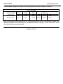
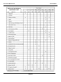
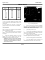
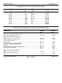
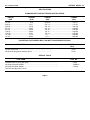
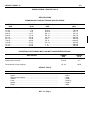
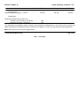
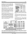
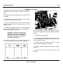
Cooling System Capacity
The capacity of the basic engine cooling system
(cylinder block, head, thermostat housing and oil cooler
housing) is shown in Table 1.
To obtain the complete amount of coolant in the cooling
system of an engine, the additional capacity of the
radiator, hoses, etc. must be added to the capacity of
the basic engine. The capacity of radiators and related
equipment should be obtained from the equipment
supplier.
Fill Cooling System
Should a daily loss of coolant be observed, and there
are no apparent leaks, there is a possibility of gases
leaking past the cylinder head water seal rings into the
cooling system. The presence of air or gases in the
cooling system may be detected by connecting a rubber
tube from the overflow pipe to a water container.
Bubbles in the water in the container during engine
operation will indicate this leakage. Another method for
observing air in the cooling system is by inserting a
transparent tube in the water outlet line.
Drain Cooling System
The engine coolant is drained by opening the cylinder
block and radiator (heat exchanger) drain cocks and
removing the cooling system filler cap. Removal of the
filler cap permits air to enter the cooling passages and
the coolant to drain completely from the system.
Drain cocks or plugs are located on each side of the 453 and 6V cylinder blocks. The 3-53 cylinder block has
a drain cock or plug located on the side of the block
opposite the oil cooler.
IMPORTANT : Drain cocks or plugs on
both sides of the engine must be
opened to drain the engine completely.
Before starting an engine, close all of the drain cocks
and fill the cooling system completely. If the unit has a
raw water pump, it should be primed, since operation
without water may cause impeller failure.
In addition to the drains on the cylinder blocks, the Inline
engines have a drain cock located on the bottom of the
oil cooler housing. The V-type engines have two drain
cocks that must be opened when draining the system.
Radiators, etc., that do not have a drain cock, are
drained through the oil cooler housing drain.
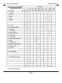
COOLING SYSTEM CAPACITY CHART
(BASIC ENGINE)
ENGINE
CAPACITY (Quarts)
3-53
8
4-53
9
6V-53
14
TABLE 1
Start the engine and, after normal operating
temperature has been reached, allowing the coolant to
expand to its maximum, check the coolant level. The
To insure that all of the coolant is drained completely
from an engine, all cooling system drains should be
opened. Should any entrapped water in the cylinder
block or radiator freeze, it will expand and may cause
damage. When freezing weather is expected, drain all
engines not adequately protected by antifreeze.
Page 27
Engine Systems
DETROIT DIESEL
Leave all of the drain cocks open until refilling the
cooling system.
The exhaust manifolds of marine engines are cooled by
the same coolant used in the engine. Whenever the
engine cooling system is drained, each exhaust
manifold drain cock, located on the bottom near the
exhaust outlet, must be opened.
pump should be removed and the radiator and engine
reverse-flushed separately to prevent dirt and scale
deposits clogging the radiator tubes or being forced
through the pump. Reverse-flushing is accomplished by
hot water, under air pressure, being forced through the
cooling system in a direction opposite to the normal flow
of coolant, loosening and forcing scale deposits out.
The radiator is reverse-flushed as follows:
Raw water pumps are drained by loosening the cover
attaching screws. It may be necessary to tap the raw
water pump cover gently to loosen it. After the water
has been removed, tighten the screws.
Flushing
The cooling system should be flushed each spring and
fall. The flushing operation cleans the system of
antifreeze solution in the spring and removes the
summer rust inhibitor in the fall, preparing the cooling
system for a new solution. The flushing operation
should be performed as follows:
1. Drain the previous season's solution from the engine.
2. Refill the cooling system with soft clean water. If the
engine is hot, fill slowly to prevent rapid cooling and
distortion of the engine castings.
3. Start the engine and operate it for 15 minutes to
circulate the water thoroughly.
4. Drain the cooling system completely.
5. Refill the system with the solution required for the
coming season.
Cooling System Cleaners
If the engine overheats and the fan belt tension and
water level are satisfactory, clean and flush the entire
cooling system. Remove scale formation by using a
quality de-scaling solvent. Immediately after using the
solvent, neutralize the system with the neutralizer. It is
important that the directions printed on the container of
the de-scaling solvent be thoroughly read and followed.
After the solvent and neutralizer have been used,
completely drain the engine and radiator and reverseflush before filling the cooling system.
Reverse-Flushing
1. Remove the radiator inlet and outlet hoses and
replace the radiator cap.
2. Attach a hose at the top of the radiator to lead water
away from the engine.
3. Attach a hose to the bottom of the radiator and insert
a flushing gun in the hose.
4. Connect the water hose of the gun to the water outlet
and the air hose to the compressed air outlet.
5. Turn on the water and, when the radiator is full, turn
on the air in short blasts, allowing the radiator to fill
between air blasts.
CAUTION: Apply air gradually. Do not exert
more than 30 psi air pressure. Too great a
pressure may rupture a radiator tube.
6. Continue flushing until only clean water is expelled
from the radiator.
The cylinder block and cylinder head water passages
are reverse-flushed as follows:
1. Remove the thermostat and the water pump.
2. Attach a hose to the water inlet of the cylinder block
to drain the water away from the engine.
3. Attach a hose to the water outlet at the top of the
cylinder block and insert the flushing gun in the hose.
4. Turn on the water and, when the water jackets are
filled, turn on the air in short blasts, allowing the engine
to fill with water between air blasts.
5. Continue flushing until the water from the engine
runs clean.
If scale deposits in the radiator cannot be removed by
chemical cleaners or reverse-flushing as outlined above,
it may be necessary to remove the upper tank and rod
out the individual radiator tubes with flat steel rods.
Circulate water through the radiator core from the
bottom to the top during this operation.
After the engine and radiator have been thoroughly
cleaned, they should be reverse-flushed. The water
Page 28
DETROIT DIESEL
Engine Systems
Miscellaneous Cooling System Checks
In addition to the above cleaning procedures, the other
components of the cooling system should be checked
periodically to keep the engine operating at peak
efficiency. The thermostat and the radiator pressure
cap should be checked and replaced, if found defective.
The cooling system hoses should be inspected and any
hose that feels abnormally hard or soft should be
replaced immediately.
Seal failure is readily noticed by a flow of water visible
at the openings in the raw water pump housing, located
between the pump mounting flange and the inlet and
outlet ports. These openings must remain open at all
times.
Also, check the hose clamps to make sure they are
tight. All external leaks should be corrected as soon as
detected. The fan belt must be adjusted to provide the
proper tension, and the fan shroud must be tight against
the radiator core to prevent recirculation of air which
may lower cooling efficiency.
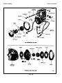
Fresh Water Pump
A centrifugal-type fresh water pump is mounted on top
of the engine oil cooler housing, either on the right-hand
or left-hand side of the engine, depending upon the,
engine model and rotation. It circulates the coolant
through the cooling system.
The pump is belt driven, by either the camshaft or
balance shaft (In-line engines) or by one of the
camshafts (V-type engines).
An impeller is pressed onto one end of the water pump
shaft, and a water pump drive pulley is pressed onto the
opposite end. The pump shaft is supported on a sealed
double-row combination radial and thrust ball bearing.
Coolant is prevented from creeping along the shaft
toward the bearing by a seal. The shaft and bearing
constitute an assembly and are serviced as such, since
the shaft serves as the inner race of the ball bearing.
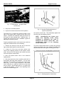
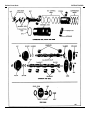
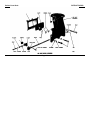
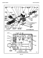
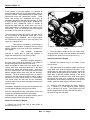
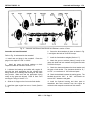
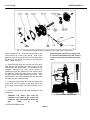
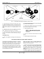
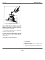
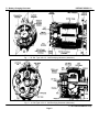
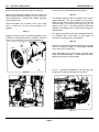
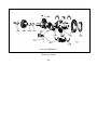
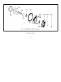
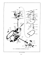
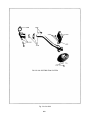
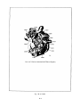
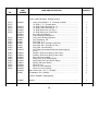
Fig. 19. Raw Water Pump Used on In-Line Engine
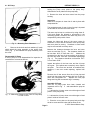
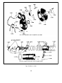
The impeller, cam and wear plate assembly, and water
seal assembly may be serviced without removing the
pump from the engine as outlined below.
1. Remove the cover and gasket.
2. Note the position of the impeller blades to aid in the
reassembly. Then grasp a blade on each side of the
impeller with pliers and pull the impeller off of the shaft.
3. The neoprene spline seal(s) can be removed from
the impeller by pushing a screw driver through the
impeller from the open end.
The sealed water pump shaft ball bearing is filled with
lubricant when assembled. No further lubrication is
required.
Contact an authorized Detroit Diesel Allison Service
Outlet if more information is needed.
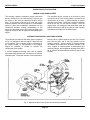
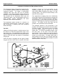
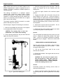
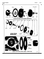
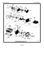
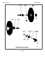
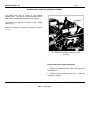
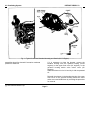
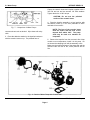
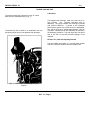
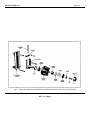
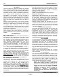
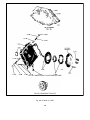
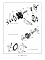
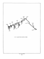
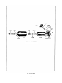
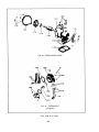
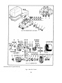
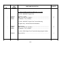
Raw Water Pump
The raw water pump (Figs. 19 and 20) is a positive
displacement pump, used for circulating raw water
through the heat exchanger to lower the temperature of
the engine coolant. It is driven by a coupling from the
end of the camshaft.
Page 29
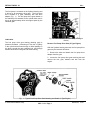
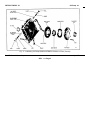
Fig. 20. Raw Water Pump Used on V-Type Engine
Engine Systems
DETROIT DIESEL
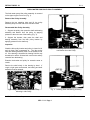
CAUTION: If the impeller is reusable,
exercise care to prevent damage to the
splined surfaces.
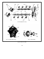
4. Remove the cam retaining screw and withdraw the
cam and wear plate assembly.
5. Remove the seal assembly from the pump used on a
V-type engine by inserting two wires with hooked ends
between the pump housing and seal with the hooks over
the edge of the carbon seal. Remove the seal seat and
gasket in the same way.
6. The seal may be removed from the pump used on
the In-line engine by drilling two holes in the seal case
and placing metal screws in the holes so that they may
be grasped and pulled with pliers. Then remove the
rubber seal ring.
A new seal may be installed in the pump used on the InLine engine by placing the rubber seal ring in its groove,
starting the seal (with the lip facing the impeller cavity)
over the shaft and tapping it into place against the seal
spacer.
9. Install the cam and wear plate assembly.
NOTE: The wear plate is round and is
doweled to the cam. The wear plate must be
installed with the cam in the pump housing
as an assembly.
10. Apply a non-hardening sealant to the cam retaining
screw-and the hole in the pump body to prevent any
leakage. Then hold the cam with the tapped hole
aligned and secure it with the screw.
7. Clean and inspect the impeller, cam and wear plate
assembly and water seal. The impeller must have a
good bond between the neoprene and the metal. If the
impeller blades are damaged, worn or have taken a
permanent set, replace the impeller. Reverse the wear
plate if it is worn excessively and remove any burrs.
Replace the seal, if necessary.
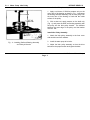
11. Compress the impeller blades to clear the off-set
cam and press the impeller on the splined shaft. The
blades must be correctly positioned to follow the
direction of rotation.
8. Install the seal assembly in the pump used on a Vtype engine as follows:
13. Turn the impeller several revolutions in the normal
direction of rotation to position the blades.
a. If the seal seat and gasket were removed, place the
gasket and seal seat over the shaft and press them into
position in the seal cavity.
14. Affix a new gasket and install the pump cover.
b. Place the seal ring securely in the ferrule, and with
the carbon seal and washer correctly positioned against
the ferrule, slide the ferrule over the shaft and against
the seal seat. Use care to ensure that the seal ring is
contained within the ferrule so that it grips the shaft.
12. Install the neoprene splined seal(s) in the bore of
the impeller.
The Jabsco raw water pump is equipped with a synthetic
rubber impeller.
Since synthetic rubber loses its
elasticity at low temperatures, impeller made of natural
rubber should be installed when it is necessary to pump
raw water that has a temperature below 40°F.
The natural rubber impeller can be identified by a stripe
of green paint between two of the impeller blades
c. Install the flat washer and then the marcel washer.
Page 30
DETROIT DIESEL
ENGINE EQUIPMENT
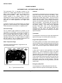
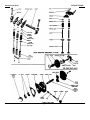
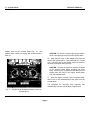
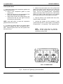
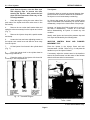
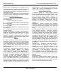
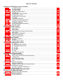
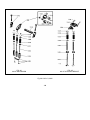
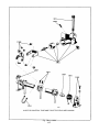
INSTRUMENT PANEL, INSTRUMENTS AND CONTROLS
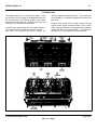
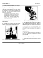
The instruments (Fig. 1) generally required in the
operation of a diesel engine consist of an oil pressure
gage, a water temperature gage, an ammeter and a
mechanical tachometer.
Also, closely related and
usually installed in the general vicinity of these
instruments are certain controls consisting of an engine
starter switch, an engine stop knob, an emergency stop
knob and, on certain applications, the engine hand
throttle.
Torqmatic converters are equipped with an oil pressure
gage and, in some instances, an oil temperature gage.
These instruments are mounted on a separate panel.
Oil Pressure Gage
The oil pressure gage registers the pressure of the
lubricating oil in the engine. As soon as the engine is
started, the oil pressure gage should start to register. If
the oil pressure gage does not register at least the
minimum pressure listed under Running in the Engine
Operating Instructions, the engine should be stopped
and the cause of low oil pressure determined and
corrected before the engine is started again.
Water Temperature Gage
The engine coolant temperature is registered on the
water temperature gage.
Ammeter
An ammeter is incorporated into the electrical circuit to
show the current flow to and from the battery. After
starting the engine, the ammeter should register a high
charge rate at rated engine speed. This is the rate of
charge received by the battery to replenish the current
used to start the engine. As the engine continues to
operate, the ammeter should show a decline in charge
rate to the battery. The ammeter will not show zero
charge rate since the regulator voltage is set higher than
the battery voltage.
The small current registered
prevents rapid brush wear in the battery-charging
alternator. If lights or other electrical equipment are
connected into the circuit, the ammeter will show
discharge when these items are operating or the engine
speed is reduced.
Tachometer
The tachometer is driven by the engine and registers the
speed of the engine in revolutions per minute (rpm).
Engine Starting Motor Switch
The starting switch is mounted on the instrument panel
with the contact button extending through the front face
of the panel. The switch is used to energize the starting
motor. As soon as the engine starts, release the switch.
Stop Knob
A stop knob is used on most applications to shut the
engine down. When stopping an engine, the speed
should be reduced to idle and the engine allowed to
operate at idle for a few minutes to permit the coolant to
reduce the temperature of the engine's moving parts.
Then the stop knob should be pulled and held until the
engine stops. Pulling on the stop knob manually places
the injector racks in the "no-fuel" position. The stop
knob should be returned to its original position after the
engine stops.
Emergency Stop Knob
Fig. 1. Typical Instrument Panel
In an emergency or if after pulling the stop knob, the
engine continues to operate, the emergency stop knob
Page 31
Engine Equipment
DETROIT DIESEL
may be pulled to stop the engine. The emergency stop
knob, when pulled, will trip the air shut-off valve located
between the air inlet housing and the blower and shut off
the air supply to the engine. Lack of air will prevent
further combustion of the fuel and stop the engine.
The emergency stop knob must be pushed back in after
the engine stops so the air shut-off valve can be opened
for restarting after the malfunction has been corrected.
Throttle Control
The engine throttle is connected to the governor speed
control shaft through linkage. Movement of the speed
control shaft changes the speed setting of the governor
and thus the engine speed.
Page 32
DETROIT DIESEL
Engine Equipment
ENGINE PROTECTIVE SYSTEMS
MANUAL SHUT-DOWN SYSTEM
The manually operated emergency engine shut-down
device, mounted in the air inlet housing, is used to stop
the engine in the event an abnormal condition should
arise. If the engine continues to run after the engine
throttle is placed in the no-fuel position, or if combustible
liquids or gases are accidentally introduced into the
combustion chamber causing overspeeding of the
engine, the shut-down device will prevent damage to the
engine by cutting off the air supply and thus stopping the
engine.
The shut-down device consists of an air shut-off valve
mounted in the air inlet housing which is retained in the
open position by a latch. A cable assembly is used to
remotely trip the latch. Pulling the emergency shutdown
knob all the way out will stop the engine. After the
engine stops, the emergency shut-down knob must be
pushed all the way in and the air shut-off valve manually
reset before the engine can be started again.
AUTOMATIC MECHANICAL SHUT-DOWN SYSTEM
The automatic mechanical shut-down system illustrated
in Fig. 2 is designed to stop the engine if there is a loss
of oil pressure, loss of engine coolant, overheating of
the engine coolant, or over-speeding of the engine.
Engine oil pressure is utilized to activate the
components of the system.
A coolant temperature-sensing valve and an adaptor
and copper plug assembly are mounted on the exhaust
manifold outlet. The power element of the temperature-
sensing valve is placed against one end of the copper
plug, and the other end of the plug extends into the
exhaust manifold. Engine coolant is directed through
the adaptor and passes over the power element of the
valve. Engine oil, under pressure, is directed through a
restricted fitting to the temperature-sensing valve and to
an oil pressure actuated bellows located on the air inlet
housing.
Fig. 2.· Mechanical Shut-Down System Schematically Illustrated
Page 33
Engine Equipment
DETROIT DIESEL
The pressure of the oil entering the bellows overcomes
the tension of the bellows spring and permits the latch to
retain the air shut-off valve in the open position. If the
oil pressure drops below a predetermined value, the
spring in the bellows will release the latch and permit the
air shut-off valve to close and thus stop the engine.
The overspeed governor, used on certain applications,
consists of a valve actuated by a set of spring-loaded
weights. Engine oil is supplied to the valve through a
connection in the oil line between the bellows and the
temperature-sensing valve. An outlet in the governor
valve is connected to the engine oil sump. Whenever
the engine speed exceeds the overspeed governor
setting, the valve (actuated by the governor weights) is
moved from its seat and permits the oil to flow to the
engine sump. This decreases the oil pressure to the
bellows, thus actuating the shut-down mechanism and
stopping the engine.
A restricted fitting, which will permit a drop in oil
pressure great enough to actuate the shut-down
mechanism, is required in the oil line between the
cylinder block oil gallery and the shut-down sensing
devices.
To be sure the protective system will function properly if
an abnormal engine condition occurs, have the system
checked periodically by your local Detroit Diesel Allison
Service Outlet.
Also make sure the air shut-off valves close each time
the engine is shut down.
Operation
To start an engine equipped with a mechanical
shutdown system, first manually open the air shut-off
valve and then press the engine starting switch. As
soon as the engine starts, the starting switch may be
released, but the air shut-off valve must be held in the
open position until the engine oil pressure increases
sufficiently to permit the bellows to retain the latch in the
open position.
During operation, if the engine oil pressure drops below
the setting of the pressure sensitive bellows, the spring
within the bellows will release the latch and permit the
air shut-off valve to close, thus stopping the engine.
If the engine coolant overheats, the temperaturesensing valve will open and permit the oil in the
protective system to flow to the engine crankcase. The
resulting decrease in oil pressure will actuate the
shutdown mechanism and stop the engine. Also if the
engine loses its coolant, the copper plug will be heated
up by the hot exhaust gases passing over it and cause
the temperature-sensing valve to open and actuate the
shut-down mechanism.
Whenever the engine speed exceeds the overspeed
governor (if used) setting, the oil in the line flows to the
sump, resulting in a decrease in oil pressure. The oil
pressure bellows then releases the latch and permits the
air shut-off valve to close.
When an engine is stopped by the action of the
shutdown system, the engine cannot be started again
until the particular device which actuated the shut-down
mechanism has returned to its normal position. The
abnormal condition which caused the engine to stop
must be corrected before attempting to start it again.
AUTOMATIC ELECTRICAL SHUT-DOWN SYSTEM
The automatic electrical shut-down system shown in Fig.
3 protects the engine against a loss of coolant,
overheating of the coolant, loss of oil pressure, or
overspeeding.
In the event one of the foregoing
conditions arises, a switch will close the electrical circuit
and energize the solenoid switch, causing the shut-down
solenoid to release the air shut-down latch and stop the
engine.
Operation
If the oil pressure drops below 10 psi, the oil pressure
switch will close the circuit and energize the shut-down
solenoid. This will activate the shut-down mechanism
and stop the engine.
A loss of coolant or an increase in coolant temperature
to approximately 203° F. will close the contacts in the
water temperature switch, thus dosing the electrical
circuit and activating the shut-down mechanism.
The water temperature switch consists of a temperatureThe electrical circuit is de-energized under normal
sensing valve and a micro-switch. The valve contacts a
operating conditions. When the engine is started, the oil
copper plug (heat probe) which extends into the exhaust
pressure switch opens when the oil pressure reaches
manifold outlet. Engine water is directed
approximately 10 psi and the fuel oil pressure switch
Page 34 closes at approximately 20 psi fuel pressure.
The water temperature switch remains open.
Page 34
DETROIT DIESEL
Engine Equipment
Fig. 4. Automatic Electrical Shut-Down System
Incorporating Hot Wire Relay
Some engines are equipped with an electrically
operated
automatic
shut-down
system
which
incorporates a hot wire relay (Fig. 4).
Fig. 3. Automatic Electrical Shut-Down System
Diagram
over the power element of the valve and should the
water temperature exceed approximately 203° F., the
valve will close the contacts in the micro-switch and
energize the shut-down circuit. If a loss of water occurs,
the heat of the exhaust gases will be transmitted through
the copper plug to the temperature-sensing valve and
cause the shut-down circuit to be activated.
If the engine speed exceeds the high speed setting of
the overspeed governor, the governor switch will close
and activate the shut-down mechanism.
When the engine is shut-down, the decrease in speed
will open the governor switch, and the decrease in oil
and fuel pressures will close the oil pressure switch and
open the fuel pressure switch, thus de-energizing the
circuit.
The cause of the abnormal conditions must then be
determined and corrected before the engine is started
again. Also, the air shut-off valve must be manually
reset in the open position before the engine can be
started.
Since the fuel pressure builds up rapidly, the fuel oil
pressure switch could close before the lubricating oil
pressure switch opens, and effect a shut-down of the
engine. The hot wire relay, however, delays the closing
of the fuel oil pressure switch for several seconds to
enable the lubricating oil pressure to build up and open
the oil pressure switch contacts.
When the lubricating oil pressure falls below 10 ± 2 psi,
the contacts in the oil pressure switch used in this
system will close and current will flow through the hot
wire relay to the solenoid. The few seconds required to
heat the hot wire relay provides sufficient delay to avoid
an engine shut-down when low oil pressure is caused by
a temporary condition such as an air bubble or a
temporary overlap in the operation of the oil pressure
switch and the fuel oil pressure switch when starting or
stopping the engine.
The water temperature switch, which remains open
during normal engine operation, is installed in the side
of the thermostat housing. The switch contacts close
when the water temperature reaches approximately
205° F. and activate the shut-down solenoid.
Page 35
Engine Equipment
DETROIT DIESEL
ALARM SYSTEM
The alarm system shown in Fig. 5 is similar to the
automatic electrical shut-down system, but uses a
warning bell in place of the air shut-off valve solenoid.
The bell warns the engine operator if the engine coolant
overheats or the oil pressure drops below the safe
operating limit.
When the engine is started and the oil pressure is
sufficient to open the oil pressure switch contacts
(opening pressure is stamped on the switch cover), the
alarm switch must be turned on manually to put the
system in operation. The water temperature switch is
normally open. Should the engine coolant exceed 205 ±
5°F., the water temperature switch will close the
electrical circuit and sound the alarm bell. Likewise, if
the oil pressure drops below the setting of the oil
pressure switch, the switch will close and cause the bell
to ring. The bell will continue to ring until the engine
operator turns the alarm switch off. The alarm switch
must also be turned off before a routine stop since the
decreasing oil pressure will close the oil pressure switch
and cause the bell to ring.
Fig. 5. Alarm System Wiring Diagram
If the alarm bell rings during engine operation, stop the
engine immediately and determine the cause of the
abnormal condition. Make the necessary corrections
before starting the engine again.
Page 36
DETROIT DIESEL
Engine Equipment
STARTING SYSTEMS
ELECTRICAL STARTING SYSTEM
The electrical system on the engine generally consists
of a battery-charging alternator, a starting motor,
voltage regulator, storage battery, starter switch and the
necessary wiring. Additional electrical equipment may
be installed on the engine unit at the option of the
owner.
Storage Battery
The lead-acid storage battery is an electrochemical
device for converting chemical energy into electrical
energy.
The battery has three major functions:
Starting Motor
The starting motor has a Sprag overrunning clutch.
Pressing the starting switch engages the starting motor
pinion with the teeth of the flywheel ring gear and
energizes the starting motor. The starting motor drives
the pinion and rotates the crankshaft. When the engine
begins to operate, the Sprag clutch permits the pinion to
overrun on its shaft, until the starting switch is released,
and prevents overspeeding the starting motor.
Starter Switch
To start the engine, a switch is used to energize the
starting motor. Release the switch immediately after the
engine starts.
Alternator
The battery-charging alternator provides the electrical
current required to maintain the storage battery in a
charged condition and to supply sufficient current to
carry any other electrical load requirements up to the
rated capacity of the alternator.
1. It provides a source of electrical power for starting
the engine.
2. It acts as a stabilizer to the voltage in the electrical
system.
3. It can, for a limited time, furnish current when the
electrical demands of the unit exceed the output of the
alternator.
The battery is a perishable item which requires periodic
servicing. A properly cared for battery will give long and
trouble-free service.
1. Check the level of the electrolyte regularly. Add
water if necessary, but do not overfill. Overfilling can
cause poor performance or early failure.
2. Keep the top of the battery clean. When necessary,
wash with a baking soda solution and rinse with fresh
water. Do not allow the soda solution to enter the cells.
3. Inspect the cables, clamps and hold-down bracket
regularly. Clean and re-apply a light coating of grease
when needed. Replace corroded, damaged parts.
4. Use the standard, quick in-the-unit battery test as the
regular service test to check battery condition.
5. Check the electrical system if the battery becomes
discharged repeatedly.
If the engine is to be stored for more than 30 days,
remove the battery. The battery should be stored in a
cool, dry place. Keep the battery fully charged and
check the level of the electrolyte regularly.
Regulator
The Lubrication and Preventive Maintenance section of
this manual covers the servicing of the starting motor
and alternator.
A voltage regulator is introduced into the electrical
system to regulate the voltage and current output of the
battery-charging alternator and to maintain a fully
charged storage battery.
Consult an authorized Detroit Diesel Allison Service
Outlet for information regarding the electrical system.
Page 37
Engine Equipment
DETROIT DIESEL
HYDRAULIC STARTING SYSTEM (HYDROSTARTER)
The Hydrostarter System schematically illustrated in Fig.
6 is a complete hydraulic system for starting internal
combustion engines.
The system is automatically
recharged after each start, and can be manually
recharged. The starting potential remains during long
periods of inactivity, and continuous exposure to hot or
cold climates has no detrimental effect upon the
Hydrostarter system. Also, the Hydrostarter torque for a
given pressure remains substantially the same
regardless of the ambient temperature.
The Hydrostarter system consists of a reservoir, an
engine-driven charging pump, a hand pump, a piston
type accumulator, a starting motor and connecting
hoses and fittings.
Operation
Hydraulic fluid flows by gravity, or a slight vacuum, from
the reservoir to either the engine-driven pump or the
hand pump inlet. Fluid discharging from either pump
outlet at high pressure flows into the accumulator and is
stored at 3250 psi under the pressure of compressed
nitrogen gas.
When the starter is engaged with the engine flywheel
ring gear and the control valve is opened, fluid under
pressure is forced out of the accumulator, by the
expanding nitrogen gas, and flows into the starting
motor which rapidly accelerates the engine to a high
cranking speed. The used fluid returns directly to the
reservoir from the starter.
The engine-driven charging pump runs continuously
during engine operation and automatically recharges the
accumulator. When the required pressure is attained in
the accumulator, a valve within the pump body opens
and the fluid discharged by the pump is by-passed to the
reservoir. The system can be shut down and the
pressure in the accumulator will be maintained.
The precharge pressure of the accumulator is the
pressure of the nitrogen gas with which the accumulator
is initially charged. This pressure must be checked
before the system pressure is raised for the initial
engine start. To check the precharge pressure, open
the relief valve, on the side of the hand pump,
approximately 1/2 turn, allowing the pressure gage to
return to zero. Close the relief valve and pump several
strokes on the hand pump. The gage should show a
rapid pressure rise from zero to the nitrogen precharge
pressure, where it will remain without change for several
additional strokes of the pump.
Fig. 6. Schematic Diagram of Hydrostarter System Showing Oil Flow
Page 38
DETROIT DIESEL
Engine Equipment
Initial Engine Start
Use the hand pump to raise the accumulator pressure.
flywheel ring gear. Release the pedal as soon as the
engine starts.
An accumulator pressure of 1500/psi when the ambient
temperature is above 40° F. will provide adequate
cranking to start the engine. Between 40° F. and 0° F.,
2500 psi should be sufficient.
Below 0°F., the
accumulator should be charged to the maximum
recommended pressure.
Although the Hydrostarter
cranks the engine faster than other starting systems,
starting aids should be. used in cold weather.
The Hydrostarter-motor is equipped with a control valve
that incorporates a threaded valve housing plug with a
1/8"-27 tapped hole in the center for installation of the
flexible hose. A 1/8"-27 pipe plug is installed when the
remote control system is not used.
NOTE: Use the priming pump to make sure
the filters, lines, manifolds and injectors are
full of fuel before attempting to start the
engine.
For ambient temperatures below 40°F., use a fluid
starting aid. Add the starting fluid just prior to moving
the Hydrostarter lever and during the cranking cycle as
required. Do not wait to add the starting fluid after the
engine is turning over, otherwise the accumulator
charge may be used up before the engine can start. In
this case, the accumulator charge must be replaced with
the hand pump.
With the engine controls set for start (throttle at least
half-open), push the Hydrostarter control lever to
simultaneously engage the starter pinion with the
flywheel ring gear and to open the control valve. Close
the valve quickly when the engine starts, te conserve
the accumulator pressure and prevent excessive
overrunning of the starter drive clutch assembly.
Three different basic types of flywheel ring gears are
used; no chamfer, Bendix chamfer, or Dyer chamfer on
the gear teeth. Some difficulty may be encountered in
engaging the starter pinion with the Dyer chamfered ring
gears. When this happens, it is necessary to disengage
and re-engage until the starter pinion is cammed in the
opposite direction enough to allow the teeth to mesh.
Remote Control System
The Hydrostarter remote control system (Fig. 7) consists
of a master cylinder, a pedal, a lever arm, two springs
and a flexible hose. It is an independent hydraulic
system using diesel fuel oil as a hydraulic fluid to
actuate the Hydrostarter control valve by means of the
pedal operated master cylinder.
The master cylinder is connected to the control valve on
the Hydrostarter by a flexible hose. Pressing on the
pedal forces the fluid through the hose to the control
valve which engages the starter pinion with the engine
Fig. 7. ·Hydrostarter Remote Control System
Springs are used to return the master cylinder pedal and
the Hydrostarter control lever to the off position.
Filling
Remove the filler cap from the reservoir and add a
sufficient quantity of hydraulic fluid (a mixture of 75%
diesel fuel and 25% SAE 10 or 30 lubricating oil) to fill
the system.
The required. amount of hydraulic fluid will vary
depending upon the size of the reservoir, length of
hydraulic hoses and the size and number of
accumulators. The reservoirs are available in 10, 12, 16
and 23 quart capacities.
In a 10 quart capacity
reservoir, add approximately 8 quarts of hydraulic fluid,
10 quarts in a 12 quart reservoir, 14 quarts in a 16 quart
reservoir or 21 quarts in a 23 quart reservoir.
Page 39
Engine Equipment
DETROIT DIESEL
1. Fill the master cylinder with fuel oil.
2. Loosen the hose fitting at the Hydrostarter control
valve.
3. Actuate the master cylinder pedal until all of the air is
discharged from the system and a solid stream of fuel
oil is being discharged with each stroke.
NOTE: When the accumulator is charged to
3000 psi and all hoses are filled, there
should be enough hydraulic fluid remaining
in the reservoir to completely cover the
screen in the bottom of the reservoir.
Purging
A by-pass valve is located on the inlet side of the hand
pump. Loosen the lock nut and rotate this valve
approximately one turn counterclockwise with a screw
driver. Operate the hand pump for 12 to 15 complete
strokes. Do not pump too rapidly. Close the by-pass
valve tightly and tighten the lock nut.
1. Move the starter control lever to engage the pinion
with the flywheel and open the control valve. While
holding the lever in this position, operate the hand pump
until the starter has turned several revolutions. Close
the control valve. Loosen the swivel hose fitting at the
discharge side of the engine-driven pump about two
turns. Operate the hand pump to force air out until oil
begins to appear at the loose fitting. Tighten the swivel
hose fitting and pressurize the system with the hand
pump sufficiently to start the engine.
2.
Perform the initial starting instructions under
Preparation for Starting Engine First Time. Then, with
the engine running at least 1500 rpm, purge the enginedriven pump of air. Break the hose connection at the
discharge side of the engine driven-pump until a full
stream of oil is discharged from the pump. Connect the
hose to the pump and alternately loosen and tighten the
swivel fitting on the discharge hose until the oil leaking
out, when the fitting is loose, appears to be free of air
bubbles. Tighten the fitting securely and observe the
pressure gage. The pressure should rise rapidly to the
accumulator ptecharge pressure (1250 psi at 70"F.),
then increase slowly, reaching 2900 to 3300 psi.
3. After the pressure has stabilized near 3000 psi,
examine all of the high pressure hoses, connections and
fittings for leaks.
4. The engine-driven pump must by-pass oil to the
reservoir when the accumulator pressure reaches
29003300 psi. To determine whether the pump by-pass
valve is operating properly, remove the reservoir filler
cap, disconnect the pump by-pass hose at the reservoir,
and hold the hose over the open reservoir filler spout.
An occasional spurt of oil may be emitted from the hose
prior to by-passing. When the by-pass valve opens, a
full and continuous stream of oil will flow from the hose.
Reconnect the hose to the reservoir and install the filler
cap.
5. Fill the reservoir to the proper level.
The Hydrostarter remote control system.
purged of air as follows:
may be
NOTE: Replenish the fluid in the master
cylinder as required during the purging
operation.
4. Tighten the hose fitting and check for leaks.
LUBRICATION AND PREVENTIVE MAINTENANCE
Inspect the system periodically for leaks. Primarily,
examine the high pressure hoses, connections, fittings
and the control valve on the starter. Make certain that
the oil level in the reservoir is sufficient to completely
cover the screen at the bottom of the tank. Make this
check after the accumulator is charged and the engine
driven pump is by-passing oil to the reservoir.
Every 2000 hours, or as conditions warrant, drain the
reservoir and remove the screen. Flush out the
reservoir and clean the screen and filler cap. Then
reinstall the screen.
Remove the bowl and element from the filter in the
engine-driven pump supply hose. Wash the bowl and
element in clean fuel oil and reassemble the filter.
Release the pressure and drain the remaining hydraulic
fluid from the system by disconnecting the hoses from
the Hydrostarter components. Then reconnect all of the
hydraulic hoses.
CAUTION: The oil pressure in the system
must be released prior to servicing the
Hydrostarter motor or other components to
prevent possible injury to personnel or
equipment.
NOTE: Make sure all hoses and fittings are
clean before any connections are made.
Fill the Hydrostarter system with new clean fluid.
Lubrication
Remove the Hydrostarter from the engine every 2000
hours for lubrication. Before removing the Hydrostarter,
release the pressure in the system by means of the
relief valve in the hand pump. Then remove the
Page 40
DETROIT DIESEL
Engine Equipment
three bolts which retain the starting motor to the flywheel
housing.
Remove the starting motor without
disconnecting the hydraulic oil hoses. This W-ill prevent
dirt and air from entering the hydraulic system.
Apply a good quality, lightweight grease on the drive
clutch pinion to make sure the clutch will slide freely
while compressing the spring. Also apply grease to the
fingers of the clutch fork and on the spool of the clutch
yoke engaged by the fork. This lubrication period may
be reduced or lengthened according to the severity of
service.
Remove the pipe plug from the starting motor drive
housing and saturate the shaft oil wick with engine oil.
Then reinstall the plug.
After lubricating, install the starting motor on the
flywheel housing and recharge the accumulator with the
hand pump.
On engines equipped with a hydraulic remote control
system, lubricate the shaft in the master cylinder
through the pressure grease fitting every 2000 hours.
Cold Weather Operation
2. Disconnect the hydraulic hoses from the starting
motor.
3. Remove the three retaining bolts and lock washers
and withdraw the starting motor from the flywheel
housing.
4. Disassemble the starting motor.
5. Wash the Hydrostarter drive clutch assembly in clean
fuel oil to remove the old lubricant.
6. When the clutch is free, apply SAE 5W lubricating
oil.
7. Reassemble the starting motor and reinstall it on the
engine. Then attach a tag to the starter noting the
lubricant used in the clutch.
8. Recharge the accumulator with the hand pump.
Marine Application
In addition to the normal Hydrostarter lubrication and
maintenance instructions, the following special
precautions must be taken for marine installations or
other cases where equipment is subject to salt spray and
air, or other corrosive atmospheres:
1. Clean all exposed surfaces and apply a coat of zincchromate primer, followed by a coat of suitable paint.
2. Apply a liberal coating of Lubriplate, type 130-AA, or
equivalent, to the following surfaces.
Occasionally, when an engine is operated in regions of
very low temperatures, the starter drive clutch assembly
may slip when the starter is engaged. If the clutch slips,
proceed as follows:
1. Release the oil pressure in the system by opening
the relief valve in the hand pump.
a. The exposed end of the starter control valve and
around the control shaft where it passes through
the clutch housing.
b. The exposed ends of the hand pump cam pin.
3. Operate all of the moving parts and check the
protective paint and lubrication every week.
CAUTION: The oil pressure in the system
must be released prior to servicing the
Hydrostarter motor or other components to
prevent possible injury to personnel or
equipment.
Consult an authorized Detroit Diesel Allison Service
Outlet for any information relating to the Hydrostarter
system.
COLD WEATHER STARTING AIDS
In a diesel engine, the fuel injected into the combustion
chamber is ignited by the heat of the air compressed
into the cylinder. However, when starting an engine in
extremely cold weather, a large part of.
NOTE: Starting aids are NOT intended to
correct for a low battery, heavy oil or other
conditions which cause hard starting. They
are to be used only when other conditions
are normal, but the air temperature is too
cold for the heat of compression to ignite
the fuel-air mixture.
the energy of combustion is absorbed by the pistons and
cylinder walls, and in overcoming the high friction
created by the cold lubricating oil.
When the ambient temperature is low, it may be
necessary to use an air heater or a starting fluid to assist
ignition of the fuel.
FLUID STARTING AID
The fluid starting aid (Fig. 8) is designed to inject a
Page 41
Engine Equipment
DETROIT DIESEL
highly volatile fluid into the air intake system at low
ambient temperatures to assist in igniting the fuel oil
injected. The fluid is contained in suitable capsules to
facilitate handling.
The starting aid consists of a cylindrical capsule
container with a screw cap, inside of which a sliding
piercing shaft operates. A tube leads from the capsule
container to a hand operated pump and another tube
leads to the atomizing nozzle threaded into a tapped
hole in the air inlet housing.
The capsule container should be mounted in a vertical
position and away from any heat.
Start the engine, using the fluid starting aid, as follows:
3. Push the piercing shaft all the way down. This will
rupture the capsule and fill the container with the
starting fluid.
4. Move the engine throttle to the maximum speed
position.
5. Engage the starter and at the same time pull the
pump plunger all the way out. Push the plunger in
slowly, forcing the starting fluid through the atomizing
nozzle into the air intake. Continue to push the pump in
until the engine starts. If the plunger is not all the way in
when the engine starts, push it in slowly until it locks in
the IN position.
6. Unscrew the cap and remove the capsule. Do not
leave the empty capsule in the container.
1. Remove the threaded cap and insert a fluid capsule
in an upright position within the container.
CAUTION: The starting fluid is toxic and
inflammable. Use caution when handling.
7. Replace the cap on the capsule container and make
sure the piercing shaft is all the way down.
Service
2. Pull the piercing shaft all the way out and install and
tighten the cap on the container.
The cold weather fluid starting aid will require very little
service. Replace the piston seal packing if the pump
leaks. If there is an excessive resistance to pumping,
the nozzle may be plugged. Remove the nozzle and
clean it.
PRESSURIZED CYLINDER STARTING AID
Start the engine during cold weather, using the "Quick
Start" starting aid system (Fig. 9) as follows: I. Press
the engine starter button.
2. Pull out the "Quick Start" knob for one or two
seconds, then release it.
3. Repeat the procedure if the engine does not start on
the first attempt.
CAUTION: Do not crank the engine more
than 30 seconds at a time when using an
electric starting motor. Always allow one
minute intervals between cranking attempts
to allow the starting motor to cool.
Service
Periodically perform the following service items to
assure good performance:
Fig. 8. Typical Fluid Starting Aid
1. Remove the fluid cylinder and lubricate the valve
around the pusher pin under the gasket with a few drops
of oil.
Page 42
DETROIT DIESEL
Engine Equipment
2. Lubricate the actuator cable.
3. Actuate the valve with the cable to distribute the oil
on the cable and allow the oil to run down through the
valve.
4. Remove any dirt from the orifice by removing the air
inlet housing fitting, the orifice block and the screen.
Then blow air through the orifice end only.
5. Assemble and tighten the air inlet housing fitting to
the actuator valve and tube.
6. Check for leakage of fluid (fogging) on the outside of
the engine air inlet housing by actuating the starting aid
while the engine is stopped.
If fogging occurs,
disassemble and retighten the air inlet housing fitting to
the housing.
CAUTION: Do not actuate the starting aid
more than once with the engine stopped.
Over-loading the engine air box with this
high volatile fluid could result in a minor
explosion.
7. Check the fluid cylinder for hand tightness.
Fig. 9.· Quick-Start Assembly
Page 43
Engine Equipment
DETROIT DIESEL
GOVERNORS
The mechanical governors are lubricated by oil splash
Horsepower requirements of an engine may vary
from the engine gear train. Oil entering the governor is
continually due to the fluctuating loads; therefore, some
directed by the revolving governor weights to the
means must be provided to control the amount of fuel
various moving parts requiring lubrication.
required to hold the engine speed reasonably constant
during such load fluctuations. To accomplish this
The hydraulic governor is lubricated by oil under
control, one of three types of governors is used on the
pressure from the engine.
engines. Installations requiring maximum and minimum
speed control, together with manually controlled
intermediate speeds, ordinarily use a limiting speed
Service
mechanical governor. Applications requiring a near
constant engine speed under varying load conditions,
Governor difficulties are usually indicated by speed
that may be changed by the operator, are equipped with
variations of the engine. However, speed fluctuations
a variable speed mechanical governor. The hydraulic
are not necessarily caused by the governor and,
governor is used where uniform engine speed is
therefore, when improper speed variations become
required under varying load conditions with a minimum
evident, the unit should be checked for excessive load,
speed droop.
misfiring or bind in the governor operating linkage. If
none of these conditions are contributing to faulty
Lubrication
governor operation, contact an authorized Detroit Diesel
Allison Service Outlet.
TRANSMISSIONS
POWER TAKE-OFF ASSEMBLIES
The front and rear power take-off units are basically
similar in design, varying in clutch size to meet the
requirements of a particular application. The power
take-off unit is attached to either an adaptor (front power
take-off) or the engine flywheel housing (rear power
take-off).
Clutch Adjustment
3. Remove the clutch adjusting ring spring lock screw
and lock from the inner clutch pressure plate and
adjusting ring. Then, while holding the clutch drive shaft
to prevent the clutch from turning, turn the clutch
adjusting ring counterclockwise as shown in fig. 10 and
tighten the clutch until the desired pressure on the outer
end of the hand lever, or at the
These instructions refer to field adjustment for clutch
facing wear. Frequency of adjustment depends upon
the amount and nature of the load. To ensure a long
clutch facing life and the best performance, the clutch
should be adjusted before slippage occurs.
When the clutch is properly adjusted, a heavy pressure
is required at the outer end of the hand lever to move
the throwout linkage to the "over center" or locked
position.
Adjust the clutch as follows:
1. Disengage the clutch with the hand lever.
Fig. 10. Adjusting Clutch
2. Remove the inspection hole cover to expose the
clutch adjusting ring. Rotate the clutch, if necessary, to
bring the adjusting ring lock within reach.
Page 44
DETROIT DIESEL
Clutch
Hand Lover Pressure
Diameter
Length
lbs.
8"
15-1/2"
55
10"
15-1/2"
80
*11-1/2"
15-3/8"
100
11-1/2"
20"
105
*Twin Disc Clutch
TABLE 1
Engine Equipment
Torque Wrench
lb-ft
56-63
87-94
129
112-120
clutch release shaft (Fig. 11), is obtained as shown in
Table 1.
When properly adjusted, the approximate pressure
required at the outer end of the hand lever to engage
the various diameter clutches is shown in the table.
These specifications apply only with the hand lever
which is furnished with the power take-off.
A suitable spring scale may be used to check the
pounds pressure required to engage the clutch.
However, a more accurate method of checking the
,clutch adjustment is with a torque wrench as shown in
Fig. 11.
To fabricate an adaptor, saw the serrated end off of a
clutch hand lever and weld a 1-1/8" nut (across the hex)
on it as shown in Fig. 11. Then saw a slot through the
nut.
When checking the clutch adjustment with a torque
wrench, engage the clutch slowly and note the amount
of torque immediately before the clutch engages (goes
over center). The specified torque is shown in Table 1.
Fig. 11. Checking Clutch Adjustment with a Torque
Wrench and Adaptor
Make a final clutch adjustment with the engine running
as follows:
1. Start the engine and operate it at idling speed
(approximately 500 rpm) with the clutch disengaged.
The speed will be sufficient to move the segments out to
the operating position.
2. Check the pounds pressure required to engage the
clutch. The engagement pressure should be the same
as that following the adjustment. If the clutch engages
at a lower pressure, the adjustment was probably made
against the unworn portion of the facing.
3. Stop the engine and readjust the clutch, making sure
all disc segments are properly positioned. Install the
inspection hole cover.
CAUTION: The thrust load on the bronze
clutch release bearing should be kept at an
absolute minimum. Therefore, the hand
lever should be positioned on the shaft as
near the 12 o'clock or 6 o'clock position as
possible. The 9 and 3 o'clock positions are
to be avoided.
TORQMATIC CONVERTERS
The Torqmatic converter is a self contained unit which
transfers and multiplies the torque of the prime mover.
This unit transmits the power through the action of oil
instead of through gears and in addition to multiplying
the torque also acts as a fluid coupling between the
engine and the equipment to be powered.
manual input disconnect clutch, and an accessory drive
for either a governor or tachometer.
Check the oil level daily. If the converter is equipped
with an input disconnect clutch, additional checks and
service will be necessary daily or at intervals determined
by the type of operation.
The converter will automatically adjust the output torque
to load requirements.
Adjust the disconnect clutches as outlined under power
take-off clutch adjustment.
There are various combinations of Torqmatic converters
with features such as: an automotive or industrial flange
on the shaft, a hydraulically operated lock-up clutch, a
Contact an authorized Detroit Diesel Allison Service
Outlet for service on Torqmatic converters.
Page 45
Engine Equipment
DETROIT DIESEL
WARNER MARINE GEAR
The Warner hydraulic marine gear assembly consists of
a hydraulically operated multiple disc clutch in
combination with a hydraulically) actuated reversing
gear train, an oil pressure regulator, an oil sump
independent of the engine oil system and an oil cooler
mounted on the engine.
Oil pressure for the operation of the marine gear is
provided by an oil pump incorporated within the gear
housing and driven continuously while the engine is
running. The oil is delivered under pressure from the
pump to a combination marine gear control valve and
pressure regulator valve.
The pressure regulator valve maintains constant
pressure over a wide speed range and the control valve
directs the oil under pressure to either the forward or
reverse piston cylinder. The operating oil pressure
range for the marine gear at operating speed is 120 to
140 psi and the maximum oil temperature is 225° F.
Minimum oil pressure is 100 psi at idle speed (600 rpm).
Shifting from forward to reverse drive through neutral
may be made at any speed; however, it is advisable to
shift at low speeds, below 1000 engine rpm, to avoid
damage to the engine, reverse gear or shaft.
The marine reverse and reduction gear is lubricated by
pressure and splash. The quantity of oil in the marine
gear will vary with the inclination of the engine and must
be properly maintained to the full mark on the dipstick to
ensure satisfactory operation.
It is recommended that vessels utilizing a marine gear
have a suitable locking device or brake to prevent
rotation of the propeller shaft when the vessel is not
under direct propulsion. If the marine gear is not in
operation and the forward motion of the vessel causes
the propeller shaft to rotate, lubricating oil will not be
circulated through the gear because the oil pump is not
in operation. Overheating and damage to the marine
gear may result unless rotation of the propeller shaft is
prevented.
Consult an authorized Detroit Diesel Allison Service
Outlet for major repairs or reconditioning of the marine
gear.
Page 46
DETROIT DIESEL
OPERATING INSTRUCTIONS
ENGINE OPERATION INSTRUCTION
PREPARATION FOR STARTING ENGINE FIRST
TIME
Before starting an engine for the first time, carefully
read and follow these instructions. Attempting to run the
engine before studying these instructions may result in
serious damage to the engine.
NOTE: When preparing to start a new or
overhauled engine or an engine which has
been in storage, perform all of the
operations listed below. Before a routine
start (at each shift), see Daily Operations in
the Lubrication and Preventive Maintenance
Chart.
Cooling System
Install all of the drain cocks or plugs in the cooling
system (drain cocks are removed for shipping).
Open the cooling system vents, if the engine is so
equipped.
Remove the filler cap and fill the cooling system with
clean, soft water or a protective solution consisting of
high boiling point type antifreeze, if the engine will be
exposed to freezing temperatures. Refer to Engine
Coolant. Keep the liquid level about two inches below
the filler neck to allow for fluid expansion.
in storage, may be insufficient for proper lubrication
when the engine is started for the first time.
It is recommended that the engine lubricating system be
charged with a pressure prelubricator, set to supply a
minimum of 25 psi oil pressure, to ensure an immediate
flow of oil to all bearings at the initial engine start-up.
The oil supply line should be attached to the engine so
that oil under pressure is supplied to the main oil gallery.
With the oil pan dry, use the prelubricator to prime the
engine with sufficient oil to reach all bearing surfaces.
Use heavy-duty lubricating oil as specified under
Lubricating Oil Specifications.
Then remove the
dipstick, wipe it with a clean cloth, insert and remove it
again to check the oil level in the oil pan. Add sufficient
oil, if necessary, to bring it to the full mark on the
dipstick. Do not overfill.
If a pressure prelubricator is not available, fill the
crankcase to the proper level with heavy-duty lubricating
oil as specified. Then pre-lubricate the upper engine
parts by removing the valve rocker covers and pouring
lubricating oil, of the same grade and viscosity as used
in the crankcase, over the rocker arms.
Turbocharger
Use a quality rust inhibitor if only water is used in the
cooling system.
Disconnect the turbocharger oil inlet line and pour
approximately one pint of clean engine oil in the line,
thus making sure the bearings are lubricated for the
initial start. Reconnect the oil line.
Close the vents, if used, after filling the cooling system.
Air Cleaner
On marine installations, prime the raw water cooling
system and open any sea cocks in the raw water pump
intake line. Prime the raw water pump by removing the
pipe plug or electrode provided in the pump outlet elbow
and pour water in the pump.
If the engine is equipped with oil bath air cleaners, fill
the air cleaner oil cups to the proper level with clean
engine oil. Do not overfill.
CAUTION: Failure to prime the raw water
pump may result in damage to the pump
impeller.
Fill the transmission case, marine gear or torque
converter supply tank to the proper level with the
lubricant specified under Lubrication and Preventive
Maintenance.
Lubrication System
Transmission
Fuel System
The lubricating oil film on the rotating parts and bearings
of a new or overhauled engine, or one which has been
Fill the fuel tank with the fuel specified under Diesel
Fuel Oil Specifications.
Page 47
Operating Instructions
DETROIT DIESEL
If the unit is equipped with a fuel valve, it must be
opened.
CAUTION: The base of a generator set must
be grounded.
To ensure prompt starting, fill the fuel system between
the pump and the fuel return manifold with fuel. If the
engine has been out of service for a considerable length
of time, prime the filter between the fuel pump and the
injectors. The filter may be primed by removing the
plug in the top of the filter cover and slowly filling the
filter with fuel.
Clutch Disengage the clutch, if the unit is so equipped.
In addition to the above, on an engine equipped with a
Hydrostarter, use a priming pump to make sure the fuel
lines and the injectors are full of fuel before attempting
to start the engine.
Before a routine start, see Daily Operations in the
Lubrication and Preventive Maintenance Chart.
NOTE: The fuel system is filled with fuel
before leaving the factory. If the fuel is still
in the system when preparing to start the
engine, priming should be unnecessary.
STARTING
Before starting the engine for the first time, perform the
operations listed under Preparation For Starting Engine
First Time.
If a manual or an automatic shut-down system is
incorporated in the unit, the control must be set in the
open position before starting the engine.
The blower will be seriously damaged if operated with
the air shut-off valve in the closed position.
Lubrication Fittings
Fill all grease cups and lubricate at all fittings with an all
purpose grease. Apply lubricating oil to the throttle
linkage and other moving parts and fill the hinged cap
oilers with a hand oiler.
Drive Belts
Starting at air temperatures below 40 F. requires the
use of a cold weather starting aid. See Cold Weather
Starting.
The instructions for the use of a cold weather fluid
starting aid will vary dependent on the type being used.
Reference should be made to these instructions ,
before attempting a cold weather start.
Adjust all drive belts as recommended under Lubrication
and Preventive Maintenance.
CAUTION: Starting fluid used in capsules is
highly inflammable, toxic and possesses
anesthetic properties.
Storage Battery
Check the battery. The top should be clean and dry, the
terminals tight and protected with a coat of petroleum
jelly and the electrolyte must be at the proper level.
NOTE: When necessary, check the battery
with a hydrometer; the reading should be
1.265 or higher.
However, hydrometer
readings should always be corrected for the
temperature of the electrolyte.
Initial Engine Start (Electric) Start an engine equipped
with an electric starting motor as follows: Set the speed
control lever at part throttle, then bring it back to the
desired no-load speed. In addition, on mechanical
governors, make sure the stop lever on the governor
cover is in the run position. Then press the starting
motor switch firmly.
If the engine fails to start within 30 seconds, release the
starting switch and allow the starting motor to cool a few
minutes before trying again. If the engine fails
Generator Set
Ambient Temperature
Where applicable, fill the generator end bearing housing
with the same lubricating oil as used in the engine.
A generator set should be connected and grounded in
accordance with the applicable local electrical codes.
Page 48
Above 40° F
40 ° to 0° F
Below 0° F
TABLE 1
Pressure Gage
Reading
1500 psi
2500 p1
3300 psi
Operating Instructions
DETROIT DIESEL
to start after four attempts, an inspection should be
made to determine the cause.
approximately five minutes, allowing it to warm-up
before applying a load.
CAUTION: To prevent serious damage to the
starter, if the engine does not start, do not
press the starting switch again while the
starting motor is running.
If the unit is operating in a closed room, start the room
ventilating fan or open the windows, as weather
conditions permit, so ample air is available for the
engine.
Initial Engine Start (Hydrostarter) An engine equipped
with a Hydrostarter may be started as follows:
Clutch
Do not engage the clutch at engine speeds over 1000
rpm.
Raise the Hydrostarter accumulator pressure with the
hand pump until the gage reads as indicated in Table 1.
Inspection
While the engine is running at operating temperature,
check for coolant, fuel or lubricating oil leaks. Tighten
the line connections where necessary to stop leaks.
Pressure Gauge
Reading
1500 psi
2500 psi
3300 psi
Ambient Temperature
Above 40°F.
40°F. to 0°F.
Below 0°F.
Engine Temperature
Set the engine controls for starting with the throttle at
least half open.
NOTE: During cold weather add starting
fluid at the same time the Hydrostarter motor
lever is moved. Do not wait to add the fluid
after the engine is turning over.
Push the Hydrostarter control lever to simultaneously
engage the starter pinion with the flywheel ring gear and
to open the control valve . Close the valve as soon as
the engine starts to conserve the accumulator pressure
and to avoid excessive over-running of the starter drive
clutch assembly.
RUNNING
Oil Pressure
Observe the oil pressure gage immediately after starting
the engine. If there is no pressure indicated within 10 to
15 seconds, stop the engine and check the lubricating
oil system. The minimum oil pressure should be at least
18 psi at 1200 rpm. The oil pressure at normal
operating speed should be 40-60 psi.
Warm-Up
Run the engine at part throttle and no-load for
Normal engine coolant temperature is 160°F. to 185°F.
Crankcase
If the engine crankcase was refilled, stop the engine
after normal operating temperature has been reached,
allow the oil to drain back into the crankcase for
approximately twenty minutes and check the oil level.
Add oil, if necessary, to bring it to the proper level on
the dipstick.
Use only the heavy duty lubricating oil specified under
Lubricating Oil Specifications.
Cooling System
Remove the radiator or heat exchanger tank cap slowly
after the engine has reached normal operating
temperature and check the engine coolant level. The
coolant level should be near the top of the opening. If
necessary, add clean soft water or a high boiling point
type antifreeze (refer to Engine Coolant).
Marine Gear
Check the marine gear oil pressure. The operating oil
pressure range for the marine gear at operating speed is
120 to 160 psi and minimum oil pressure is 100 psi at
idle speed (600 rpm).
Page 49
DETROIT DIESEL
Operating Instructions
Stop" knob pushed in before the engine is ready to start
again.
Turbocharger
Make a visual inspection of the turbocharger for leaks
and excessive vibration. Stop the engine immediately if
there is an unusual noise in the turbocharger.
Fuel System
If the unit is equipped with a fuel valve, close it. Fill the
fuel tank; a full tank minimizes condensation.
Avoid Unnecessary Engine Idling
During long engine idling periods, the engine coolant
temperature will fall below the normal operating range.
The incomplete combustion of fuel in a cold engine will
cause crankcase dilution, formation of lacquer or
gummy deposits on the valves, pistons and rings and
rapid accumulation of sludge in the engine.
Exhaust System
Drain the condensation from the exhaust line or silencer.
Cooling System
Drain the cooling system if it is not protected with
antifreeze and freezing temperatures are expected.
NOTE: When prolonged engine idling is
necessary, maintain at least 800 rpm.
Leave the drains open. Open the raw water drains of a
heat exchanger cooling system.
STOPPING
Normal Stopping
Crankcase
1. Release the load and decrease the engine speed.
Put all shift levers in the neutral position.
Check the oil level in the crankcase. Add oil, if
necessary, to bring it to the proper level on the dipstick.
2. Allow the engine to run at half speed or slower with
no load for a short time, then move the stop lever to
stop to shut down the engine.
Transmission
Check and, if necessary, replenish the oil supply in the
transmission.
Emergency Stopping
Clean Engine
If the engine does not stop after using the normal
stopping procedure, pull the "Emergency Stop" knob all
the way out. This control cuts off the air to the engine.
Do not try to restart again until the cause for the
malfunction has been found and corrected.
CAUTION: The emergency shut-down
system should never be used except in an
emergency.
Use of the emergency shut-down can cause oil to be
sucked past the oil seals and into the blower housing.
Clean and check the engine thoroughly to make certain
it will be ready for the next run.
Refer to Lubrication and Preventive Maintenance and
perform all of the daily maintenance operations. Also
perform the operations required for the number of hours
or miles the engine has been in operation.
Make the necessary adjustments and minor repairs to
correct difficulties which became apparent to the
operator during the last run.
The air shut-off valve, located on the blower air inlet
housing, must be reset by hand and the "Emergency
Page 50
DETROIT DIESEL
Operating Instructions
ALTERNATING CURRENT POWER GENERATOR SET OPERATING INSTRUCTIONS
These instructions cover the fundamental procedures for
operating an alternating current power generator set
(Fig. 1). The operator should read these instructions
before attempting to operate the generator set.
it can be controlled to permit a reduction in the load
should a normal load increase occur while the set is
operating. Locate the supplementary load outside the
engine room, if desirable, to provide adequate cooling.
Never operate a generator set for a short (15 minute)
interval the engine will not reach normal operating
temperature in so short a period.
Loading the generator set to 40% of the generator rating
and operating it for one-hour intervals will bring the
engine and generator to normal operating temperatures
and circulate the lubricants properly. Abnormal amounts
of moisture, carbon and sludge are due primarily to low
internal operating temperatures which are much less
likely to occur when the set is tested properly.
Avoid operating the set for extended periods at noload.
Ideally, operate the set for one hour with at least 40%
load (generator rating).
PREPARATION FOR STARTING
When a test must be made with a line load of less than
40% of the generator rating, add a supplementary' load.
Connect the supplementary load to the load terminals of
the control cabinet circuit breaker so that the generator
can be "loaded" whenever the breaker is closed.
Before attempting to start a new or an overhauled
engine or an engine which has been in storage, perform
all of the operations listed under Preparation for Starting
Engine First Time. Before a routine start, see Daily
Operations in the Lubrication and Preventive
Maintenance Chart.
Make certain that the supplementary load is such that
In addition to the Engine Operating Instructions, the
Fig. 1. Location of Controls on Power Generator Set
Page 51
DETROIT DIESEL
Operating Instructions
following instructions also apply when operating an
alternating current power generator set.
1. Before the first start, check the generator main
bearing oil reservoir.
If necessary, add sufficient
lubricating oil, of the same grade as used in the engine
crankcase, to bring it to the proper level on the sight
gage.
RUNNING
Observe the engine oil pressure gage immediately after
starting the engine. If there is no oil pressure indicated
within 10 to 15 seconds, stop the engine and check the
engine lubricating system. If the oil pressure is observed
to be normal, increase the throttle setting to cause the
engine to run at its synchronous speed.
2. Check the interior of the generator for dust or
moisture. Blow out dust with low pressure air (25 psi
maximum). If there is moisture on the interior of the
generator, it must be dried before the set is started.
Refer to the appropriate Delco Products Maintenance
bulletin.
PREPARING GENERATOR FOR LOAD
After the engine is warmed up (or the oil pressure has
stabilized) prepare the generator set for load as follows:
1. Bring the engine up to the rated speed.
3. The air shut-off valve located in the air inlet housing
must be in the open or reset position.
3. Turn the voltage regulator rheostat knob slowly in a
clockwise direction to raise the voltage, while watching
the voltmeter, until the desired voltage is attained.
4. Refer to Fig. 1 and place the circuit breaker in the
off position.
2. Turn the instrument switch to the desired position.
5. If the generator set is equipped with synchronizing
lamps, place the lamp switch in the off position.
4. If the generator set is equipped with a frequency
meter, adjust the engine speed with the vernier throttle
knob until the desired frequency is indicated on the
meter.
6.
Turn the voltage regulator
counterclockwise to its lower limit.
5. Make sure all power lines are clear of personnel,
then place the circuit breaker control in the on position.
rheostat
knob
7. Make sure the power generator set has been cleared
of all tools or other objects which might interfere with its
operation.
NOTE: Perform Step 5 only if the generator
set is not being paralleled with an existing
power source. If it is being paralleled with a
power source already on the line, read and
follow the instructions under Paralleling
before turning the circuit breaker control to
the on position.
STARTING
If the generator set is located in a closed space, start the
ventilating fan or open the doors and windows, as
weather permits, to supply ample air to the engine.
The engine may require the use of a cold weather
starting aid if the ambient temperature is below 40° F.
Refer to Cold Weather Starting Aids.
Press the throttle button and turn the throttle control
(Fig. 1) counterclockwise to a position midway between
run and stop. Then press the starting switch firmly.
If the engine fails to start within 30 seconds, release the
starting switch and allow the starting motor to cool a few
minutes before trying again. If the engine fails to start
after four attempts, an inspection should be made to
determine the cause.
CAUTION: To prevent serious damage to the
starter, if the engine does not start, do not
press the starting switch again while the
starting motor is rotating.
PARALLELING
If the load conditions require an additional unit to be
placed on the line, the following instructions will apply to
power generator sets of equal capacity, with one
generator set in operation on the line.
1. Prepare the generator set to be paralleled as outlined
under Preparation For Starting, Starting, Running and
Items 1 through 4 under Preparing Generator for Load.
2. Check the voltmeter (Fig. 1); the voltage must be
the same as the line voltage. Adjust the voltage
regulator rheostat control if the voltages are not the
same.
3.
Place the synchronizing lamp switch, of the
generator set to be paralleled, in the on position.
Page 52
DETROIT DIESEL
Operating Instructions
4. Turn the vernier throttle knob until both units are
operating at approximately the same frequency as
indicated by the slow change in the brilliancy of the
synchronizing lamps.
5. When the synchronizing lamps glow and then go out
at a very slow rate, time the dark interval. Then, in the
middle of this interval, turn the circuit breaker control to
the on position. This places the incoming generator set
on the line, with no load. The proper share of the
existing load must now be placed on this generator.
6. The division of the kilowatt load between the
alternating current generators operating in parallel
depends on the power supplied by the engines to the
generators as controlled by the engine governors and is
practically independent of the generator excitation.
Divide the kilowatt load between the generators by
turning the vernier throttle knob counterclockwise on the
incoming generator and clockwise on the generator that
has been carrying the load (to keep the frequency of the
generators constant) until both ammeters read the
same, indicating that each generator is carrying its
proper percentage of the total K.W. load.
7. The division of the reactive KVA load depends on the
generator excitation as controlled by the voltage
regulator.
Divide the reactive load between the
generators by turning the voltage regulator rheostat
control on the incoming generator (generally clockwise
to raise the voltage) until the ammeters read the same
on both generator sets and the sum of the readings is
minimum.
NOTE: The generator sets are equipped with
a resistor and current transformer connected
in series with the voltage coil of the
regulator
(crosscurrent
compensation)
which equalizes most but not all of the
reactive KVA load between the generators.
8. When the load is 80 per cent power factor lagging
(motor and a few lights only), turn the vernier throttle
knob on the incoming generator until the ammeter on
CHANGE 3
that unit reads approximately 40 per cent of the total
current load.
9. Rotate the voltage regulator rheostat control on the
incoming generator clockwise to raise the voltage until
the ammeters read the same on both units.
NOTE: If a load was not added during
paralleling, the total of the two ammeter
readings should be the same as the reading
before paralleling.
Readjust the voltage
regulator rheostat on the incoming
generator, if necessary.
10. To reset the load voltage, turn the voltage regulator
rheostat controls slowly on each unit. It is necessary to
turn the controls the same amount and in the same
direction to keep the reactive current equally divided.
Power generator sets with different capacities can also
be paralleled by dividing the load proportionately to their
capacity.
STOPPING
The procedure for stopping a power generator set or
taking it out of parallel is as follows:
1. Turn off all of the load on the generator when
stopping a single engine unit.
2. Shift the load from the generator when taking it out of
parallel operation by turning the vernier throttle knob
until the ammeter reads approximately zero.
3. Place the circuit breaker control in the of position.
4. Turn the voltage regulator rheostat control in a
counterclockwise direction to the limit of its travel.
5. Press the throttle button and turn the throttle control
to stop to shut-down the engine.
NOTE: When performing a tune-up on a
generator set that will be operated in parallel
with another unit, adjust the speed droop as
specified in Engine Tune-Up.
Page 53
DETROIT DIESEL
Operating Instructions
CAUTION: Machine designed to operate at the following maximum pressure settings and volumes.
Pressure Settings
and Volumes
PSI Relief Setting
Main
Winch
Main
2200
FUNCTION SWING
Aux
Boom
Winch
Winch
Main
Main
3000
3000
G.P.M. Volume
10 min
60 min
60 min
Main
2500
Telescope
Main
2800
Ports
2500
34 min
18 min
18 min
NOTE: Priority Valve Pressure Setting 1650 psi. Volume and pressures are to be checked with hydraulic oil at
operating temperature and 1780 engine rpm. Unauthorized pressure settings in excess of the above values
voids all warranties expressed or implied.
Change 3 Page 54
DETROIT DIESEL
LUBRICATION AND PREVENTIVE MAINTENANCE
To obtain the best performance and long life from a
Detroit Diesel engine, the Operator must adhere to the
following schedule and instructions on lubrication and
preventive maintenance.
The daily instructions pertain to routine or daily starting
of an engine and not to a new engine or one that has
not been operated for a considerable period of time.
For new or stored engines, carry out the instructions
given under Preparation for Starting Engine First Time
under Operating Instructions.
The time intervals given in the chart on the following
page are actual operating hours or miles of an engine.
If the lubricating oil is drained immediately after an
engine has been run for some time, most of the
sediment will be in suspension and, therefore, will drain
readily.
All authorized Detroit Diesel Allison Service Outlets are
prepared to service engines with the viscosity and
grade of lubricants recommended on the following
pages.
Page 55
Preventive Maintenance
Detroit Diesel
Page 56
DETROIT DIESEL
Preventive Maintenance
Item 1
Check the oil level daily before starting the engine. Add
oil, if necessary, to bring it to the proper level on the
dipstick.
Select the proper grade of oil in accordance with the
instructions in the Lubricating Oil Specifications.
It is recommended that new engines be started with 100
hour oil change periods. The drain interval may then be
gradually increased, or decreased, following the
recommendations of an independent oil analysis
laboratory or the oil supplier (based upon the oil sample
analysis) until the most practical oil change period has
been established.
Item 2
Items 3 and 4
Install new engine oil filter elements and gaskets each
time the engine oil is changed. Check for oil leaks after
starting the engine. If the engine is equipped with a
governor oil filter, change the element every 1,000
hours.
top of the heat exchanger tank or the radiator upper
tank.
Item 3
Check the coolant level daily and maintain it near the
Clean the cooling system every 1,000 hours or 30,000
miles using a good radiator cleaning compound in
accordance with the instructions on the container. After
the cleaning operation, rinse the cooling system
thoroughly with fresh water. Then fill the system with
soft water, adding a good grade of rust inhibitor or a
high boiling point type antifreeze (refer to Engine
Coolant). With the use of a proper antifreeze or rust
inhibitor, this interval may be lengthened until, normally,
this cleaning is done only in the spring or fall. The
length of this interval will, however, depend upon an
inspection for rust or other deposits on the internal walls
of the cooling system. When a thorough cleaning of the
cooling system is required, it should be reverse-flushed.
If the cooling system is protected by a coolant filter and
conditioner, the filter element should be changed every
500 hours or 15,000 miles.
Item 4
Inspect all of the cooling system hoses at least once
every 500 hours or 15,000 miles for signs of
deterioration. Replace the hoses if necessary.
Items 1 and 2
Page 57
Preventive Maintenance
DETROIT DIESEL
Item 5
Inspect the exterior of the radiator core every 1.,000
hours or 30,000 miles and, if necessary, clean it with a
quality grease solvents such as Oleum and compressed
air. Do not use fuel oil, kerosene or gasoline. It may be
necessary to clean the radiator more frequently if the
engine is being operated in extremely dusty or dirty
areas.
Item 6
Every 500 hours drain the water from the heat
exchanger raw water inlet and outlet tubes. Then
remove the zinc electrodes from the inlet side of the
Item 7
raw water pump and the heat exchanger. Clean the
electrodes with a wire brush or, if worn excessively,
replace with new electrodes. To determine the condition
of a used electrode, strike it sharply against a hard
surface; a weakened electrode will break.
Drain the cooling system, disconnect the raw water
pipes at the outlet side of the heat exchanger and
remove the retaining cover every 1,000 hours and
inspect the heat exchanger core. If a considerable
amount of scale or deposits are present, contact an
authorized Detroit Diesel Allison Service Outlet.
Item 7
Item 5
Check the prime on the raw water pump; the engine
should not be operated with a dry pump. Prime the
pump, if necessary, by removing the pipe plug provided
in the pump inlet elbow and adding water. Reinstall the
plug.
Item 8
Keep the fuel tank filled to reduce condensation to a
minimum. Select the proper grade of fuel in accordance
with the Diesel Fuel Oil Specifications.
Open the drain at the bottom of the fuel tank every 500
hours or 15,000 miles to drain off any water or sediment.
Item 9
Item 6
Install new elements every 300 hours or 9,000 miles or
when plugging is indicated.
A method of determining when elements are plugged to
the extent that they should be changed is based on the
fuel pressure at the cylinder head fuel inlet manifold and
the inlet restriction at the fuel pump.
Page 58
DETROIT DIESEL
Preventive Maintenance
to the extent that they should be changed is based on
the fuel pressure at the cylinder head fuel inlet manifold
and the inlet restriction at the fuel pump. In a clean
system, the maximum pump inlet restriction must not
exceed 6 inches of mercury. At normal operating
speeds (1800-28()0 rpm), the fuel pressure is 45 to 70
psi. Change the fuel filter elements whenever the inlet
restriction (suction ) at the fuel pump reaches 12 inches
of mercury at normal operating speeds and whenever
the fuel pressure at the inlet manifold falls to 45 psi.
air cleaner cups and center tubes every 8 hours or less
if operating conditions warrant. Wash the cups and
elements in clean fuel oil and refill the cups to the level
mark with the same grade of heavy duty oil as used in
the engine. The frequency of servicing may be varied
to suit local dust conditions.
Item 10
Clean or replace the element in the dry-type air cleaner
when the restriction indicator instrument indicates high
restriction or when a water manometer reading at the air
inlet housing indicates the maximum allowable air inlet
restriction (refer to the Air Inlet Restriction chart in the
Trouble Shooting section). Refer to the instructions in
the Air System section for servicing the dry-type air
cleaner.
Remove the dirty oil and sludge from the oil bath-type
It is recommended that the body and fixed element in
the heavy-duty oil bath type air cleaner be serviced
every 500 hours, 15,000 miles or as conditions warrant.
Item 11
Item 9
With the engine running, check for flow of air from the
air box drain tubes every 1,000 hours or 30,000 miles.
If the tubes are clogged, remove, clean and reinstall the
tubes. The air box drain tubes should be cleaned
periodically even though a clogged condition is not
apparent. If the engine is equipped with an air box drain
tank, drain the sediment periodically. If the engine is
equipped with an air box drain check valve, replace the
valve every 500 hours or 15,000 miles.
Item 12
Clean the externally mounted crankcase breather
assemblies every 1,000 hours or 30,000 miles. This
cleaning period may be reduced or lengthened
according to severity of service. Clean the internally
mounted breather pads at time of engine overhaul, or
sooner if excessive crankcase pressure is observed.
Item 10
Item 11
Page 59
Preventive Maintenance
DETROIT DIESEL
mounted breather pads at time of engine overhaul, or
sooner if, excessive crankcase pressure is observed.
Reinstall the screen and gasket assemblies with the
screen side of the assemblies toward the blower.
Remove the crankcase breather from the engine and
wash the steel mesh pad (element) in fuel oil and dry it
with compressed air. Reinstall the breather assembly.
Inspect for evidence of blower seal leakage.
Item 13
Item 14 The electrical starting motor is lubricated at the
time of original assembly. Oil can be added to the oil
wicks, which project through each bushing and contact
the armature shaft, by removing the pipe plugs on the
outside of the motor. The wicks should be lubricated
whenever the starting motor is taken off the engine or
disassembled.
Inspect the blower screen and gasket assemblies every
1,000 hours or 30,000 miles and, if necessary, clean the
screens in fuel oil and dry them with compressed air.
The Sprag overrunning clutch drive mechanism should
be lubricated with a few drops of light engine oil
whenever the starting motor is overhauled.
Clean the breather cap, mounted on the valve rocker
cover, in clean fuel oil every time the engine oil is
changed.
Item 15 Lubricate the alternator bearings or bushings
with 5 or 6 drops of engine oil at the hinge cap oiler
every 200 hours or 6,000 miles.
Some alternators have a built-in supply of grease, while
others use sealed bearings. In these latter two cases,
additional lubrication is not necessary.
Item 12
The slip rings and brushes of an alternator can be
inspected through the end frame assembly. If the slip
rings are dirty, they should be cleaned with 400 grain or
finer polishing cloth. Never use emery cloth to clean
slip rings. Hold the polishing cloth against the slip rings
with the alternator in operation and blow away
Item 14
Item 13
Page 60
DETROIT DIESEL
Preventive Maintenance
Item 15
all dust after the cleaning operation. If the slip rings are
rough or out of round, replace them.
Inspect the terminals for corrosion and
connections and the wiring for frayed insulation.
loose
Item 16
Check the specific gravity of the electrolyte in each cell
of the battery every 100 hours or 3,000 miles. In warm
weather, however, it should be checked more frequently
due to a more rapid loss of water from the electrolyte.
The electrolyte level should be maintained in
accordance
with
the
battery
manufacturer's
recommendations.
Item 17
Lubricate the tachometer drive every 100 hours or 3,000
miles with an all purpose grease at the grease fitting. At
temperatures above +30°F., use a No. 2 grade grease.
Use a No. I grade grease below this temperature.
Item 18
Lubricate the throttle control mechanism every 200
hours or 6,000 miles with an all purpose grease. At
Item 17
temperatures above +30°F., use a No. 2 grade grease.
Use a No. 1 grade grease below this temperature.
Lubricate all other control mechanisms, as required, with
engine oil.
Item 19
There is no scheduled interval for performing an engine
tune-up.
As long as the engine performance is
satisfactory, no tune-up should be needed. Minor
adjustments In the valve and injector operating
mechanisms, governor, etc. should only be required
periodically to compensate for normal wear on parts.
Item 20
New drive belts will stretch after the first few hours of
operation. Run the engine for 15 seconds to seat the
belts and readjust the tension. Then check the belts and
retighten the fan drive, pump drive and battery charging
alternator drive belts after 1/2 hour or 15 miles and
again after 8 hours or 140 miles of operation.
Thereafter, check the tension of the drive
Page 61
Preventive Maintenance
DETROIT DIESEL
belts every 200 hours or 6,000 miles and adjust, if
necessary. Too tight a belt is destructive to the bearings
of the driven part; a loose belt will slip.
BELT TENSION CHART (lbs/belt)
Fan Drive
Generator Drive
Model 2 or 3 Single
Two 3/8" One
One9/16
belts
belt
or
1/2"
belt "
1/2'-belts belt
3,4-53 40-50
40-50
50-70
40-50
6v-53
60-80 80-100 40-50
50-70
40-50
All
For 3-point or triangular drive use o tension of 90120.
Replace all belts In a set when one is worn. Single belts
of similar size should not be used as a substitute for a
matched belt set; premature belt wear can result
because of belt length variation. All belts in a matched
set are within .032 " of their specified center distances.
NOTE: When installing or adjusting
an accessory drive belt, be sure the
bolt at the accessory adjusting pivot
point is properly tightened, as well
as the bolt in the adjusting slot.
Item 20
Item 24
Adjust the belt tension so that a firm push with the
thumb, at a point midway between the two pulleys, will
depress the belt 1/2" to 3/4". If a belt tension gage such
as BT-33-73FA or equivalent is available, adjust the belt
tension as outlined in the chart.
On engines equipped with a Hydrostarter, refer to the
Hydraulic Starting System in the section on Engine
Equipment
for
preventive
maintenance
and
lubrication.
Item 25
Item 21
Lubricate the overspeed governor, if it is equipped with
a hinge-type cap oiler or oil cup, with 5 or 6 drops of
engine oil every 500 hours. Avoid excessive lubrication
and do not lubricate the governor while the engine is
running.
To clean either the hair or polyurethane type air
compressor air strainer element, saturate and squeeze it
in fuel oil, or any other cleaning agent that would not be
detrimental to the element, until dirt free. Then dip it in
lubricating oil and squeeze it dry before placing it back
in the air strainer.
Item 22
At a major engine overhaul, discard the bearings in the
fan hub assembly used in radiator cooled engines. Pack
the hub assembly, using new bearings, with Texaco
Premium RB grease or an equivalent Lithium base
multi-purpose grease.
For replacement of the air strainer element, contact the
nearest Bendix Westinghouse dealer; replace with the
polyurethane element, if available.
Item 23
Check the shut-down system every 300 operating hours
or each month to be sure it will function when needed.
There is no scheduled interval for performing an
inspection on the Airesearch turbocharger. As long as
the turbocharger is operating satisfactorily and there
Item 26
Page 62
DETROIT DIESEL
Preventive Maintenance
inspection is necessary. When service is required,
contact an authorized Detroit Diesel Allison Service
Outlet.
Item 27
The power generator requires lubrication at only one
point the ball bearing in the end frame.
If the bearing is oil lubricated, check the oil level in the
sight gage every 300 hours; change the oil every six
months. Use the same grade of oil as specified for the
engine. Maintain the oil level to the line in the sight
gage. Do not overfill After adding oil, recheck the oil
level after running the generator for several minutes.
If the bearing is grease lubricated, a new generator has
sufficient grease for three years of normal service.
Thereafter, it should be lubricated at one year intervals.
To lubricate the bearing, remove the filler and relief
plugs on the side and the bottom of the bearing
reservoir. Add grease until new grease appears at the
relief plug opening. Run the generator a few minutes to
vent the excess grease; then reinstall the plugs.
Item 25
The following greases, or their equivalents, are
recommended:
Keystone 44H......................Keystone Lubrication Co.
BRB Lifetime........................ Socony Vacuum Oil Co.
NY and NJ F926 or F927..... NY and NJ Lubricant Co.
After 100 hours on new brushes, or brushes in
generators that have not been in use over a long period,
remove the end frame covers and inspect the brushes,
commutator and collector rings.
If there is no
appreciable wear on the brushes, the inspection interval
may be extended until the most practicable period has
been established (not to exceed six months). To
prevent damage to the commutator or the collector
rings, do not permit the brushes to become shorter than
3/4 inch.
Keep the generator clean inside and out. Before
removing the end frame covers, wipe off the loose dirt.
The loose dirt and dust may be blown out with low
pressure air (25 psi maximum). Remove all greasy dirt
with a cloth.
Item 27
is no appreciable loss of power, no vibration or unusual
noise and no oil leaks, only a periodic
Item 28
Lubricate all of the power take-off bearings with an all
purpose grease such as Shell Alvania No. 2, or
Page 63
Preventive Maintenance
equivalent. Lubricate sparingly to avoid getting grease
on the clutch facing.
DETROIT DIESEL
Open the cover on the side of the clutch housing (8" and
10" diameter clutch) and lubricate the clutch release
sleeve collar through the grease fitting every 8 hours.
On the 11-1/2" diameter clutch, lubricate the collar
through the fitting on the side of the clutch housing
every 8 hours.
Lubricate the clutch drive shaft pilot bearing through the
fitting in the outer end of the drive shaft (8" and 10"
diameter clutch power take-offs) every 50 hours of
operation. One or two strokes with a grease gun should
be sufficient. The clutch drive shaft pilot bearing used
with the 11-1/2" diameter clutch power take-off is
prelubricated and does not require lubrication.
Lubricate the clutch drive shaft roller bearings through
the grease fitting in the clutch housing every 50 hours
under normal operating conditions (not continuous) and
more often under severe operating conditions or
continuous operation.
Lubricate the clutch release shaft through the fittings at
the rear of the housing every 500 hours of operation.
Lubricate the clutch levers and links sparingly with
engine oil every 500 hours of operation. Remove the
inspection hole cover on the clutch housing and
lubricate the clutch release levers and pins with a hand
oiler. To avoid getting oil on the clutch facing, do not
over lubricate the clutch release levers and pins.
Check the clutch facing for wear every 500 hours.
Adjust the clutch if necessary.
Item 29
Check the oil level in the Torqmatic converter and
supply tank daily. The oil level must be checked while
the converter is operating, the engine idling and the oil
is up to operating temperature (approximately 200°F). If
the converter is equipped with an input disconnect
clutch, the clutch must be engaged.
Check the oil level after running the unit a few minutes.
The oil level should be maintained at the proper level on
the dipstick. If required, add hydraulic transmission fluid
type "C-2" (see chart). Do not overfill the converter as
too much oil will cause foaming and high oil
temperature.
Prevailing
Ambient
Temperature
Above - 10 F
Item 28
Recommended Oil
Specification
Hydraulic Transmission Fluid, Type C2.
Below -10 F
Hydraulic Transmission Fluid, Type C2Auxiliary preheat required to raise
temperature in the sump to a
temperature above -10 F.
0IL RECOMMENDATIONS
authorized Detroit Diesel Allison Service Outlet as this
usually requires disassembly. Under severe operating
conditions, the oil should be changed more often.
The converter oil breather, located on the oil level
indicator (dipstick), should be cleaned each time the
converter oil is changed. This can be accomplished by
allowing the breather to soak -in a solvent, then drying it
with compressed air.
The full-flow oil filter element should be removed, the
shell cleaned and a new element and gasket installed
each time the converter oil is changed.
Lubricate the input clutch release bearing and ball
bearing every 50 hours with an all purpose grease
through the grease fittings provided on the clutch
housing. This time interval may vary depending upon
the operating conditions. Over-lubrication will cause
grease to be thrown on the clutch facing, causing the
clutch to slip.
The oil should be changed every 500 hours of operation.
Also, the oil should be changed whenever it shows
traces of dirt or effects of high operating temperature as
evidenced by discoloration or strong odor. If the oil
shows metal contamination, contact an
Page 64
DETROIT DIESEL
Preventive Maintenance
idle speed for a few minutes to fill the lubrication
system. Stop the engine. Then immediately after
stopping the engine, check the oil level in the marine
gear. Bring the oil level up to the proper level on the
dipstick. Use the same grade of lubricating oil that is
used in the engine. Do not overfill.
Change the oil every 200 hours. After draining the oil
from the unit, clean the removable oil screen thoroughly
before refilling the marine gear with oil.
TWIN DISC MARINE GEAR:
Check the marine gear oil level daily. Check the oil
level with the engine running at low idle speed and the
gear in neutral, Keep the oil up to the proper level on the
dipstick. Use oil of the same heavy-duty grade and
viscosity that is used in the engine.
Item 30
Item 30
WARNER MARINE GEAR:
Check the oil level daily. Start and run the engine at
Change the oil every 200 hours. Remove and clean the
oil inlet strainer screen after draining the oil and before
refilling the marine gear. The strainer is located in the
sump at the lower end of the pump suction line. When
refilling after an oil drain, bring the oil up to the proper
level on the dipstick (approximately 5 quarts).
Page 65
DETROIT DIESEL
DETROIT DIESEL FUEL OIL SPECIFICATIONS
fuels and lubricants of good quality regularly
Detroit Diesel designs, develops, and manufactures
provided by the petroleum industry through
commercial diesel engines to operate on diesel fuels
retail outlets. It is accordingly contrary to the
classified by the A.S.T.M. as Designation D975 (grades
policy of General Motors to recommend the
I-D and 2-D). These grades are very similar to grades
regular and continued use of supplementary
DF-l and DF-2 of Federal Specification VV-F-800.
additives in such fuels and lubricants.
"This policy should not be confused with the fact
that certain supplementary additives may
effectively and economically solve specific
operating problems which occasionally arise in
some
vehicles.
In
such
instances,
supplementary additives may be developed on
the basis of suitable tests to remedy such
problems without otherwise causing harm to
vehicles. These selected products are then
given official GM part numbers and made
available for use in appropriate service
applications.
"While General Motors Corporation assumes
responsibility for the additives selected by it to
remedy specific operating problems, it cannot,
of course, accept responsibility for the many
other additives which are constantly being
marketed."
Residual fuels and furnace oils, generally, are not
considered satisfactory for Detroit Diesel engines. In
some regions, however. fuel suppliers may distribute
one fuel that is marketed as either diesel fuel (A.S.T.M.
D-975) or domestic heating fuel (A.S.T.M. D-396)
sometimes identified as furnace oil. In this case, the
fuel should be investigated to determine whether the
properties conform with those shown in the FUEL OIL
SELECTION CHART. presented in this specification.
The FUEL OIL SELECTION CHART also will serve as a
guide in the selection of the proper fuel for various
applications. The fuels used must be clean, completely
distilled, stable, and non-corrosive. DISTILLATION
RANGE. CETANE NUMBER, and SULFUR CONTENT
are three of the most important properties of diesel fuels
that must be controlled to insure optimum combustion
and minimum wear. Engine speed, load, and ambient
temperature influence the selection of fuels with respect
to distillation range and cetane number. The sulfur
content of the fuel must be as low as possible to avoid
excessive deposit formation, premature wear, and to
minimize the sulfur dioxide exhausted into the
atmosphere.
To assure that the fuel you use meets the required
properties, enlist the aid of a reputable fuel oil supplier.
The responsibility for clean fuel lies with the fuel
supplier as well as the operator.
During cold weather engine operation, the cloud point
(the temperature at which wax crystals begin to form in
diesel fuel) should be 10° F below the lowest expected
fuel temperature to prevent clogging of the fuel filters by
wax crystals.
At temperatures below 20° F, consult an authorized
Detroit Diesel service outlet, since particular attention
must be given to the cooling system, lubricating system,
fuel system, electrical system, and cold weather starting
aids for efficient engine starting and operation.
STATEMENT OF POLICY ON FUELS AND
LUBRICANTS
In answer to requests concerning the use of fuel and
lubricating oil additives. the following excerpts have
been taken from a policy statement of General Motors
Corporation:
Although the stated Corporation policy is self-explanatory,
the following is emphasized: Detroit Diesel does not
recommend or support the use of any supplementary fuel
or lubricant additives. These include all products marketed
as fuel conditioners, smoke suppressants, masking agents,
reodorants, tune-up compounds, top oils, break-in oils,
graphitizers and friction reducing compounds.
NOTE:
The manufacturer's warranty
applicable to Detroit Diesel engines
provides in part that the provisions of
such warranty shall not apply to any
engine unit which has been subject to
misuse,
negligence
or
accident.
Accordingly, malfunctions attributable
to neglect or failure to follow the
manufacturer's fuel or lubricating
recommendations indicated above may
not be within the coverage of the
warranty.
FUEL OIL SELECTION CHART
Typical
Application
City Buses
All Other
Applications
"It has been and continues to be Gene(al
Motors policy' to build motor vehicles that will
operate satisfactorily on the commercial
Page 66
General Fuel
Classification
No. 1-D
Winter No. 2-D
Summer No. 2-D
Final
Boiling
Point
(Max)
550°F
675°F
675°F
Cetane
No.
(Min)
45
45
40
Sulfur
Content
(Max)
0.30%
0.50%
0.50%
NOTE: When prolonged idling periods
or cold weather conditions below 320 F
are encountered, the use of lighter
distillate fuels may be more practical.
The same consideration must be made
when operating at altitudes above 5,000
ft.
DETROIT DIESEL
Fuel, Oil and Coolant Specifications
DETROIT DIESEL LUBRICATING OIL SPECIFICATIONS
Page 67
Fuel, Oil and Coolant Specifications
DETROIT DIESEL
ENGINE COOLANT
among but not necessarily all the materials which make
Engine coolant is considered as any solution which is
up dissolved solids. Water, within the limits specified in
circulated through the engine to provide the means for
Tables 1 and 2 of Figure 1, is satisfactory as an engine
heat transfer from the various engine components. In
coolant when proper inhibitors are added.
general, water containing various materials in solution is
used for this purpose.
CORROSION INHIBITORS
The function of the coolant is basic in the design and the
successful operation of the engine and must be carefully
A corrosion inhibitor is a water soluble chemical
selected and properly maintained.
compound which protects the metallic surfaces of the
cooling system against corrosive attack. Some of the
COOLANT REQUIREMENTS
more commonly used corrosion inhibitors are
A suitable coolant solution must meet the following five
chromates, borates, nitrates, nitrites and soluble oil.
basic requirements:
Depletion of all types of inhibitors occur through normal
1. Provide for adequate heat transfer.
operation and therefore strength levels must be
maintained by the addition of inhibitors at prescribed
2. Provide a corrosion resistant environment within the
intervals. Always follow the supplier's recommendations
cooling system.
on inhibitor usage and handling.
3. Prevent formation of scale or sludge deposits in the
cooling system.
4. Be compatible with the cooling system hose and
seal materials.
5. Provide adequate freeze protection during cold
weather operation.
Normally requirements 1 through 4 are satisfied by
combining a suitable water with reliable inhibitors.
When operating conditions dictate the need for freeze
protection, a solution of suitable water and an ethylene
glycol type antifreeze containing adequate inhibitors will
provide a satisfactory coolant.
WATER
Any water, whether of drinking quality or not, will
produce a corrosive environment in the cooling system.
Also, scale deposits may form on the internal surfaces
of the cooling system due to the mineral content of the
water. Therefore, water selected as a coolant must be
properly treated with inhibitors to control corrosion and
scale deposition.
To determine if a particular water is suitable for use as a
coolant when properly inhibited, the following
characteristics must be considered. The concentration
of (I) chlorides, (2) sulfates, (3) total hardness and (4)
dissolved solids. These materials are objectionable for
a number of reasons: chlorides and/or sulfates will
accelerate corrosion, while hardness (percentage of
magnesium and calcium present) will cause deposits of
scale. Total dissolved solids may cause scale deposits,
sludge deposits, corrosion or a combination of these.
Chlorides, sulfates, magnesium and calcium are
Chromates
Sodium chromate and potassium dichromate are two of
the best and more commonly used water system
corrosion inhibitors. However, the restrictive use of
these materials, due to ecology considerations, has
deemphasized their use in favor of non-chromates.
Care should be exercised in handling these materials
due to their toxic nature.
Chromate inhibitors must not be used in ethylene glycol
antifreeze solutions. Chromium hydroxide, commonly
called "green slime", can result from the use of
chromate inhibitors with permanent type antifreeze.
This material deposits on the cooling system passages,
reducing the heat transfer rate and will result in engine
overheating. Engines which have operated with a
chromate inhibited water must be chemically cleaned
before the addition of ethylene glycol type antifreeze. A
commercial heavy duty descaler should be used in
accordance with the manufacturer's recommendation for
this purpose.
Soluble Oil
Soluble oil has been used as a corrosion inhibitor for
many years. It has, however, required very close
attention relative to the concentration level due to
adverse effects on heat transfer if the concentration
exceeds 1% by volume. For example: 1-1/4% of
soluble oil in the cooling system increases fire deck
temperatures 6% and a 2-1/2% concentration raises
Page 68
DETROIT DIESEL
Fuel, Oil and Coolant Specifications
TABLE 1
PARTS PER
MILLION
40
100
340
170
Chlorides (Maximum)
Sulfates (Maximum)
Total Dissolved Solids (Maximum)
Total Hardness (Maximum)
GRAINS PER
GALLON
2.5
5.8
20
10
Refer to Table 2 for evaluation of water intended for use in a coolant solution
TABLE 2
Figure 1
fire deck temperature up to 15%. Soluble oil is not
either water or a water and ethylene glycol solution.
recommended as a corrosion inhibitor.
INHIBITOR SYSTEMS
Non-Chromates
Non-chromate inhibitors (borates, nitrates, nitrites, etc.)
An inhibitor system is considered as a combination of
provide corrosion protection in the cooling system with
the basic advantage that they can be used with
Page 69
Fuel, Oil and Coolant Specifications
DETROIT DIESEL
COOLANT INHIBITOR CHART
Inhibitor or
Corrosion
Inhibitor
Inhibitor System
Type
Sodium chromate
Chromate
Potassium dichromate
Chromate
Perry filter elements:
5020 (type OS)
Chromate
S-453 (Spin-on)
Chromate
5030 (type OS)
@Non-chromate
S-331 (Spin-on)
@Non-chromate
5070 (type OS)
#Non-chromate
S-473 (Spin-on)
# Non-chromate
Lenroc filter element
Non-chromate
Fleetguard filter elements:
DCA (canister)
Non-chromate
DCA (Spin-on)
Non-chromate
AC filter elements:
DCA (canister)
Non-chromate
DCA (Spin-on)
Non-chromate
Luber-Finer
filter
elements:
LW-4739 (canister)
Non-chromate
LFW-4744 (spin-on)
non-chromate
Nalcool 2000 (liquid)
Non-chromate
Perry LP-20 (liquid)
Non-chromate
Lubercool (liquid)
Nonchromate
Dowtherm cooling system conditioner
Non-chromate
*Dowtherm 209, or equivalent.
(@Perry "Year Around" formula.
# Perry "Universal" formula.
System
No
No
Water
Yes
Yes
Inhibitor
Ethylene
Glycol
Base
Antifreeze
No
No
Yes
Yes
Yes
Yes
Yes
Yes
Yes
Yes
Yes
Yes
Yes
Yes
Yes
Yes
No
No
Yes
Yes
Yes
Yes
Yes
No
No
No
No
No
No
No
Yes
Yes
Yes
Yes
Yes
Yes
No
No
Yes
Yes
Yes
Yes
Yes
Yes
No
No
Complete
Inhibitor
Compatability
*Methoxy
Propanol
Base
Antifreeze
No
No
Yes
Yes
Yes
Yes
Yes
Yes
Yes
Yes
Yes
Yes
Yes
Yes
Yes
Yes
Yes
No
No
No
No
No
Yes
Yes
Yes
Yes
Figure 2
chemical
compounds
which
provide
corrosion
protection, pH control and water softening ability.
Corrosion protection has been discussed earlier under
the section on Corrosion Inhibitors. The pH control is
used to maintain an acid free solution. The water
softening ability deters formation of mineral deposits.
Inhibitor systems are available in various forms such as
coolant filter elements, liquid and dry bulk inhibitor
additives and as an integral part of permanent
antifreeze.
Coolant Filter Elements
Replaceable elements are available with various
chemical inhibitor systems. Care should be used in the
selection of elements relative to inhibitor compatibility
with coolant solutions shown in Figure 2.
Problems have developed from the use of the
magnesium lower support plate used by some
manufacturers in their coolant filters. The magnesium
Page 70
DETROIT DIESEL
Fuel, Oil and Coolant Specifications
Figure 3
plate will be attacked by solutions which will not be
detrimental to other metals in the cooling system. The
dissolved magnesium will be deposited in the hottest
zones of the engine where heat transfer is most critical
(Figure 3). The use of aluminum or zinc in preference
to magnesium is recommended to eliminate this type of
deposit.
A high chloride coolant will have a detrimental effect on
the water softening capabilities of systems using ionexchange resins.
Accumulations of calcium and
magnesium ions removed from the coolant and held
captive by the zeolite resin can be released into the
coolant by a regenerative process caused by high
chloride content solutions.
Bulk Inhibitor Additives
Commercially packaged inhibitor systems are available
which can be added directly to the engine coolant or to
bulk storage tanks containing coolant solution.
Both chromate and non-chromate systems are available
and care should be taken regarding inhibitor
compatability with other coolant constituents (Figure 2).
A non-chromate inhibitor system is recommended for
use in Detroit Diesel engines.
The non-chromate
systems can be used with either water or ethylene glycol
antifreeze solutions and provide corrosion protection, pH
control and water softening. Some of the approved nonchromate inhibitor systems offer the additional
advantage of a simple on site test to determine
protection level and, since they are added directly to the
coolant, require no additional hardware or plumbing.
Figure 4
ANTIFREEZE
When freeze protection is required, an ethylene glycol
base permanent antifreeze should be used. An inhibitor
system is included in this type of antifreeze and no
additional inhibitors are required on initial fill if a
minimum antifreeze concentration of 30% by volume is
used. Solutions of less than 30% concentration do not
provide sufficient corrosion protection. Concentrations
over 67% adversely affect freeze protection and heat
transfer rates (Figure 4).
Methoxy propanol base antifreeze may be used for
freeze protection in Series 53 engines. Before installing
methoxy propanol base antifreeze in an engine, the
entire cooling system should be drained, flushed with
clean water, and examined for rust, scale, contaminants,
etc.
Page 71
Fuel, Oil and Coolant Specifications
DETROIT DIESEL
If deposits are present, the cooling system must be
chemically cleaned with a commercial grade heavy-duty
de-scaler.
Inhibitor depletion will occur in ethylene glycol base
antifreeze through normal service. The inhibitors should
be replenished at approximately 500 hour or 20,000 mile
intervals with a non-chromate inhibitor system.
Commercially available inhibitor systems (Fig. 2) may
be used to re-inhibit antifreeze solutions.
2. If freeze protection is required, always use ethylene
glycol antifreeze.
3. Re-inhibit antifreeze with a non-chromate inhibitor
system.
4. Always follow the manufacturer's recommendations
on inhibitor usage and handling.
5. Do not use soluble oil.
Several brands of permanent antifreeze are available
with sealer additives. The specific type of sealers vary
with the manufacturer. Antifreeze with sealer additives
is not recommended for use in Detroit Diesel engines
due to plugging problems throughout various areas of
the cooling system.
6. Chromate inhibitors should never be used with
permanent antifreeze.
COOLANT RECOMMENDATIONS
1. Always use a properly inhibited coolant.
9. Do not mix ethylene glycol base antifreeze with
methoxy propanol base antifreeze in the cooling system.
7. Sealer type antifreeze should not be used.
8. Maintain prescribed inhibitor strength.
Page 72
DETROIT DIESEL
ENGINE TUNE-UP PROCEDURES
There is no scheduled interval for performing an engine
tune-up.
As long as the engine performance is
satisfactory, no tune-up should be needed. Minor
adjustments in the valve and injector operating
mechanisms, governor, etc. should only be required
periodically to compensate for normal wear on parts.
Three types of governors are used.
Since each
governor has different characteristics, .the tune-up
procedure varies accordingly. The three types are:
1.
Limiting speed mechanical.
2.
Variable speed mechanical.
3.
Hydraulic.
The mechanical engine governors are identified by a
name plate attached to the governor housing. The
letters D.W.-L.S. stamped on the name plate denote a
double-weight limiting speed governor. A single-weight
variable speed governor name plate is stamped S.W.V.S.
Normally, when performing a tune-up on an engine in
service, it is only necessary to check the various
adjustments for a possible change in the settings.
However, if the cylinder head, governor or injectors
have been replaced or overhauled, then certain
preliminary adjustments are required before the engine
is started.
between adjustments to maintain normal operating
temperature.
Tune-Up Sequence for Mechanical Governor
1.
Adjust the exhaust valve clearance.
2.
Time the fuel injectors.
3.
Adjust the governor gap.
4.
Position the injector rack control levers.
5.
Adjust the maximum no-load speed.
6.
Adjust the idle speed.
7.
Adjust the buffer screw.
8.
Adjust the throttle booster spring (variable
speed governor only).
9.
Adjust the supplementary governing device (if
used).
Tune-Up Sequence for Hydraulic Governor
1.
Adjust the exhaust valve clearance.
2.
Time the fuel injectors.
3.
Adjust the fuel rod.
4.
Position the injector rack control levers.
5.
Adjust the load limit screw.
6.
Adjust the speed droop.
7.
Adjust the maximum no-load speed.
The preliminary adjustments consist of the first four
items in the tune-up sequence. The procedures are the
same except that the valve clearance is greater for a
cold engine.
To tune-up an engine completely, all of the adjustments
are made by following the applicable tune-up sequence
given below after the engine has reached the normal
operating temperature.
Since the adjustments are
normally made while the engine is stopped, it may be
necessary to run the engine
Page 73
NOTE:
Use
new
valve
gasket(s)after each tune-up.
rocker
cover
Engine Tune-Up
DETROIT DIESEL
EXHAUST VALVE CLEARANCE ADJUSTMENT
The correct exhaust valve clearance at normal engine
operating temperature is important for smooth, efficient
operation of the engine.
Insufficient valve clearance can result in loss of
compression, misfiring cylinders, and eventually burned
valve seats and valve seat inserts. Excessive valve
clearance will result in noisy operation, especially in the
low speed range.
Whenever the cylinder head is overhauled, the exhaust
valves reconditioned or replaced, or the valve
operating mechanism is replaced or disturbed in any
way, the valve clearance must first be adjusted to the
cold setting to allow for normal expansion of the engine
parts during the engine warm-up period. This will
ensure a valve setting which is close enough to the
specified clearance to prevent damage to the valves
when the engine is started.
All of the exhaust valves may be adjusted, in firing order
sequence, during one full revolution of the crankshaft.
Refer to the General Specifications at the front of the
manual for the engine firing order.
TWO VALVE CYLINDER HEADS
Cold Engine
1.
Place the speed control lever in the idle speed
position. If a stop lever is provided, secure it in the nofuel position.
2.
Remove the loose dirt from the valve rocker
cover(s) and remove the cover(s).
3.
Rotate the crankshaft, manually or with the
starting motor, until the injector follower is fully
depressed on the cylinder to be adjusted.
5.
Place a .012" feeler gage, J 9708, between the
valve stem and the rocker arm (Fig. 1). Adjust the push
rod to obtain a smooth pull on the feeler gage.
6.
Remove the feeler gage. Hold the push rod
with a 5/16"wrench and tighten the lock nut with a 1/2
"wrench.
7.
Recheck the clearance. At this time, if the
adjustment is correct, the .010"gage will pass freely
between the end of the valve stem and the rocker arm
and the .012 " gage will not pass through.
8.
Check and adjust the remaining valves in the
same manner as outlined above.
CAUTION: If a wrench is used on the crankshaft
bolt, do not turn the engine in a left-hand
direction of rotation as the bolt will be loosened.
Hot Engine
4.
Loosen the exhaust valve rocker arm push rod
lock nut.
Maintaining normal engine operating temperature is
particularly important when making the final valve
clearance adjustment. If the engine is allowed to cool
off before setting any of the valves, the clearance, when
running at full load, may become insufficient.
1.
With the engine at normal operating
temperature (160 -185°F.), recheck the exhaust valve
clearance with feeler gage J 9708. At this time, if the
valve clearance is correct, the .008" gage will pass
freely between the end of the valve stem and the rocker
arm and the .010" gage will not pass through. Readjust
the push rod, if necessary.
2.
After the exhaust valve clearance has been
adjusted, check the fuel injector timing.
Fig. 1 - Adjusting Valve Clearance (Two-Valve
Cylinder Head)
Page 74
DETRIOIT DIESEL
Engine Tune-Up
FOUR VALVE CYLINDER HEADS
4.
Loosen the exhaust valve rocker arm push rod
lock nut.
5.
Place a .027" feeler gage, J 9708, between the
end of one valve stem and the rocker arm bridge (Fig.
2). Adjust the push rod to obtain a smooth pull on the
feeler gage.
6.
Remove the feeler gage. Hold the push rod
with a 5/16"wrench and tighten the lock nut with a 1/2"
wrench.
7.
Recheck the clearance. At this time, if the
adjustment is correct, the .025" gage will pass freely
between the end of one valve stem and the rocker arm
bridge and the .027" gage will not pass through.
Readjust the push rod if necessary.
Fig. 2 - Adjusting Valve Clearance (Four-Valve
Cylinder Head)
8.
Check and adjust the remaining exhaust valves,
in the same manner as above.
Cold Engine
1.
Place the speed control lever in the idle speed
position. If a stop lever is provided, secure it in the nofuel position.
2.
Remove the loose dirt from the valve rocker
cover(s) and remove the cover(s).
3.
Rotate the crankshaft until the injector follower
is fully depressed on the cylinder to be adjusted.
CAUTION: If a wrench is used on the crankshaft
bolt, do not turn the engine in a left-hand direction of
rotation as the bolt will be loosened.
Hot Engine
Maintaining normal engine operating temperature is
particularly important when making the final valve
clearance adjustment. If the engine is allowed to cool
off before setting any of the valves, the clearance, when
running at full load, may become insufficient.
1.
With the engine at normal operating
temperature (160°-185"F.), recheck the exhaust valve
clearance with gage J 9708. At this time, if the valve
clearance is correct, the .023" gage should pass freely
between the end of one valve stem and the rocker arm
bridge and the .025" feeler gage should not. Readjust
the push rod, if necessary.
2.
After the exhaust valve clearance has been
adjusted, check the fuel injector timing.
Page 75
Engine Tune-Up
DETROIT DIESEL
TIMING FUEL INJECTOR
Injector
*35
35
40
45
S40
S45
S50
L40
N40
N45
N50
Timing
Dimension
1.508
1.484
1.484
1.484
1.460
1.460
1.460
1.460
1.460
1.460
1.460
Tool
Number
J 8909
J 1242
J 1242
J 1242
J 1853
J 1853
J 1853
J 1853
J 1853
J 1853
J 1853
*Reefer Car
To time a fuel injector properly, the injector follower
must be adjusted to a definite height in relation to the
injector body.
All of the injectors can be timed, in firing order
sequence, during one full revolution of the crankshaft.
Time Fuel Injector
After the exhaust valve clearance has been adjusted,
time the fuel injector as follows:
1.
Place the speed control lever in the idle speed
position. If a stop lever is provided, secure it in the nofuel position.
2.
Rotate the crankshaft, manually or with the
starting motor, until the exhaust valves are fully
depressed on the particular cylinder to be timed.
CAUTION: If a wrench is used on the crankshaft
bolt at the front of the engine, do not turn the
crankshaft in a left-hand direction of rotation or
the bolt will be loosened.
Fig. 3 - Timing Fuel Injector
3.
Place the small end of the injector timing gage
(see table for correct timing gage) in the hole provided
in the top of the injector body, with the flat of the gage
toward the injector follower as shown in Fig. 3.
4.
Loosen the push rod lock nut.
5.
Turn the push rod and adjust the injector rocker
arm until the extended part of the gage will just passover the top of the injector follower.
6.
Hold the push rod and tighten the lock nut.
Check the adjustment and readjust, if necessary.
7.
Time the remaining injectors as outlined above.
8.
If no further engine tune-up is required, use a
new gasket(s) and install the valve rocker cover(s).
Page 76
DETROIT DIESEL
Engine Tune-Up
LIMITING SPEED MECHANICAL GOVERNOR AND INJECTOR RACK CONTROL ADJUSTMENT
IN-LINE ENGINES
The double-weight limiting speed governor is mounted
on the rear end plate of the engine and is driven by a
gear that extends through the end plate and meshes
with either the camshaft gear or the balance shaft gear,
depending upon the engine model.
After adjusting the exhaust valves and timing the fuel
injectors, adjust the governor and position the injector
rack control levers.
NOTE: Before proceeding with the governor
injector rack adjustments, disconnect
supplementary governing device.
After
adjustments are completed, re-connect
adjust the supplementary governing device.
and
any
the
and
3.
Start the engine and adjust the idle speed screw
(Fig. 7) to obtain the desired engine idle speed. Hold
the screw an tighten the lock nut to hold the adjustment.
NOTE: The recommended idle speed for nonEPA certified engines is 500-600 rpm, but may
vary with special engine applications.
4.
Stop the engine, clean and remove the governor
cover and the valve rocker cover. Discard the gaskets.
5.
Start and run the engine, between 800 and 1000
rpm by manual operation of the injector control tube
lever.
CAUTION: Do not overspeed the engine.
Adjust Governor Gap
With the engine stopped and at operating temperature,
adjust the governor gap as follows:
1.
Remove the high-speed spring retainer cover.
2.
Back out the buffer screw (Fig. 8) until it
extends approximately 5/8" from the lock nut.
6. Check the gap between the low-speed spring cap
and the high-speed spring plunger with a .0015 " feeler
gage. If the gap setting is incorrect, reset the gap
adjusting screw (Fig. 1). If the setting is correct, the
.0015" movement can be seen by placing a few drops of
oil into the governor gap and pressing a screw driver
against the gap adjusting screw. Movement of
Fig. 1 - Adjusting Governor Gap
Fig. 2 - Positioning the Rear Injector Rack
Page 77
Engine Tune-Up
DETROIT DIESEL
the cap toward the plunger will force the oil from the gap
in the form of a small bead.
establish a guide for adjusting the remaining injector
rack control levers.
7.
Hold the gap adjusting screw and tighten the
lock nut.
1.
Disconnect any linkage attached to the speed
control lever.
8.
2.
Turn the idle speed adjusting screw until 1/2"of
the threads (12-14 threads) project from the lock nut,
when the nut is against the high-speed plunger.
Recheck the gap and readjust if necessary.
9.
Stop the engine and, using a new gasket, install
the governor cover. The governor cover should be
placed on the housing with the pin of the speed control
lever projecting into the slot of the differential lever.
CAUTION: A false fuel rack setting may result if
the idle speed adjusting screw is not backed out
as noted above.
10.
Install the screws and lock washers finger tight.
Pull the cover away from the engine and tighten the
screws. This step will properly locate the cover on the
governor housing.
NOTE: This adjustment lowers the tension of
the low-speed spring so it can be easily
compressed.
This permits closing the low
speed gap without bending the fuel rods or
causing the yield mechanism springs to yield or
stretch.
Position Injector Rack Control Levers
The position of the injector racks must be correctly set in
relation to the governor. Their position determines the
amount of fuel injected into each cylinder and ensures
equal distribution of the load. Properly positioned
injector rack control levers with the engine at full-load
will result in the following:
1.
Speed control lever at the full-fuel position.
2.
Governor low-speed gap closed.
3.
High-speed spring plunger on the seat in the
governor control housing.
4.
Injector racks in the full-fuel position. Adjust the
rear injector rack control lever first to
3.
Back out the buffer screw approximately 5/8", if
it has not already been done.
4.
Loosen all of the inner and outer injector rack
control lever adjusting screws (Fig. 2). Be sure all of
the levers are free on the injector control tube.
5.
Move the speed control lever to the maximum
speed position. Turn the inner adjusting screw down on
the rear injector rack control lever until a step-up in
effort is noted. This will place the rear injector rack in
the full-fuel position. Turn down the outer adjusting
screw until it bottoms lightly on the injector control tube.
Then alternately tighten both the inner and outer
adjusting screws. This should result in placing the
governor linkage and control tube assembly in the
Fig. 3 - Checking Rotating Movement of
Injector Control Rack
Fig. 4 - Checking Injector Rack "Sprint”
Page 78
DETROIT DIESEL
Engine Tune-Up
same positions that they will attain while the engine is
running at full-load.
6.
To be sure of the proper rack adjustment, hold
the speed control lever in the full-fuel position and press
down on the injector rack with a screw driver or finger tip
and note "rotating" movement of the injector control rack
(Fig. 3) when the speed control lever is in the maximum
speed position. Hold the speed control lever in the
maximum speed position and, using a screw driver,
press downward on the injector control rack. The rack
should tilt downward (Fig. 4) and when the pressure of
the screw driver is released, the control rack should
"spring" back upward.
If the rack does not return to its original position, it is too
loose. To correct this condition, back off the outer
adjusting screw slightly and tighten the inner adjusting
screw slightly.
The setting is too tight if, when moving the speed control
lever from the no-speed to the maximum speed
position, the injector rack becomes tight before the
speed control lever reaches the end of its travel (as
determined by the stop under the governor cover). This
will result in a step-up in effort required to move the
speed control lever to the end of its travel. To correct
this condition, back off the inner adjusting screw slightly
and tighten the outer adjusting screw slightly.
IMPORTANT : The above step should result in
placing the governor linkage and control tube
assembly in the same position that they will attain
while the engine is running at full load.
7.
To adjust the remaining injector rack control
levers, remove the clevis pin from the fuel rod and the
injector control tube lever, hold the injector control racks
in the full-fuel position by means of the lever on the end
of the control tube. Turn down the inner adjusting screw
on the injector rack control lever of the adjacent injector
until the injector rack has moved into the full-fuel
position and the inner adjusting screw is bottomed on
the injector control tube. Turn the outer adjusting screw
down until it bottoms lightly on the injector control tube.
Then alternately tighten both the inner and outer
adjusting screws.
8.
Recheck the rear injector rack to be sure that it
has remained snug on the ball end of the injector rack
control lever while adjusting the adjacent injector. If the
rack of the rear injector has become loose, back off the
inner adjusting screw slightly on the adjacent injector
rack control lever. Tighten the outer adjusting screw.
When the settings are correct, the racks of both injectors
must be snug on the ball end of their respective rack
control levers.
NOTE: Overtightening of the injector rack
control
lever
adjusting
screws
during
installation or adjustment can result in damage
to the injector control tube. The recommended
torque of the adjusting screws is 24-36 in-lbs.
Fig 5 - Adjusting Maximum No-Load engine
Speed (Type A)
Fig. 6 - Governor spring Assemblies
Page 79
Engine Tune-Up
DETROIT DIESEL
b. Remove the high-speed spring from the highspeed spring plunger and add or remove shims
(Fig. 6) as required to establish the desired
engine no-load speed.
9.
Position the remaining injector rack control
levers as outlined in Steps 6 and 7.
10.
lever.
Connect the fuel rod to the injector control tube
NOTE For each .010" shim added, the engine
speed will be increased approximately 10 rpm.
11.
Turn the idle speed adjusting screw in until it
projects 3/16" from the lock nut to permit starting the
engine. Tighten the lock nut.
c. Install the high-speed spring on the plunger and
install the spring assembly in the governor
housing.
Install the spring retainer in the
governor housing and tighten it securely.
12.
Use a new gasket and replace the valve rocker
cover.
Adjust Maximum No-Load Engine Speed
All governors are properly adjusted before leaving the
factory.
However, if the governor has been
reconditioned or replaced, and to ensure the engine
speed will not exceed the recommended no-load speed
as given on the engine option plate, set the maximum
no-load speed as follows:
TYPE A GOVERNOR SPRINGS (Fig. 6):
1.
Loosen the lock nut (Fig. 5) and back off the
high-speed spring retainer approximately five turns.
2.
With the engine at operating temperature and
no-load on the engine, place the speed control lever in
the full-fuel position.
Turn the high-speed spring
retainer IN until the engine is operating at the
recommended no-load speed.
The best method of determining the engine speed is
with an accurate tachometer.
d. Start the engine and recheck the engine no-load
speed. Repeat the procedure as necessary to
establish the no-load speed.
Adjust Idle Speed
With the maximum no-load speed properly adjusted,
adjust the idle speed as follows:
1.
With the engine running at normal operating
temperature and with the buffer screw backed out to
avoid contact with the differential lever, turn the idle
speed adjusting screw (Fig. 7) until the engine is
operating at approximately 15 rpm below the
recommended idle speed.
NOTE: The recommended idle speed for nonEPA certified engines is 500-6 rpm, but may
vary with special engine applications.
2.
Hold the idle speed adjusting screw and tighten
the lock nut.
3.
Hold the high-speed spring retainer and tighten
the lock nut.
TYPE B GOVERNOR SPRINGS (Fig. 6):
1.
Start the engine and after it reaches normal
operating temperature, remove the load from the engine
2
Place the speed control lever in the maximum
speed position and note the engine speed.
3.
Stop the engine and, if necessary, adjust the noload speed as follows:
a. Remove the high-speed spring retainer, highspeed spring and plunger.
CAUTION: To prevent the low-speed spring and
cap from dropping into the governor, be careful
not to jar the assembly while it is being
removed.
PAGE 80
Fig. 7 - Adjusting Engine Idle Speed
DETROIT DIESEL
Engine Tune -Up
3.
Install the high-speed spring cover and tighten
the two bolts.
Adjust Buffer crew
With the idle peed properly set, adjust the buffer screw
as follows:
1.
With the engine running at normal operating
temperature, turn the buffer screw in (Fig. 8) so it
contacts the differential lever as lightly as possible and
still eliminates engine roll.
NOTE: Do not increase the engine idle speed
more than 15 rpm with the buffer screw.
Fig. 8 - Adjusting Buffer Screw
2.
Recheck the maximum no-load speed. If it has
increased more than 25 rpm, back off the buffer screw
until the increase is less than 25 rpm.
3.
Page 81
Hold the buffer screw and tighten the lock nut.
Engine Tune-Up
DETROIT DIESEL
LIMITING SPEED MECHANICAL GOVERNOR AND INJECTOR RACK CONTROL ADJUSTMENT
6V-53 ENGINE
The limiting speed mechanical governor is mounted at
the rear of the engine, between the flywheel housing
and the blower (Fig. 1). The governor is driven by the
right blower rotor drive gear. The left blower rotor drive
gear is driven by a shaft, that passes through the
governor housing, from the engine gear train. There are
two types of limiting speed governor assemblies. The
difference in the two governors is in the spring
mechanism (Fig.
7).
One has a long spring
mechanism, the other has a short spring mechanism.
After adjusting the exhaust valves and timing the fuel
injectors, adjust the governor and position the injector
rack control, levers.
NOTE: Before proceeding with the governor
injector rack adjustments, disconnect
supplementary governing device.
After
adjustments are completed, re-connect
adjust the supplementary governing device.
and
any
the
and
2.
Back out the buffer screw (Fig. 9) until it
extends approximately 5/8" from the lock nut.
CAUTION: Do not back the buffer screw out
beyond the limits given, or the control link lever
may disengage the differential lever.
3.
Start the engine and loosen the idle speed
adjusting screw lock nut. Then adjust the idle screw
(Fig. 8) to obtain the desired engine idle speed. Hold
the screw and tighten the lock nut to hold the
adjustment.
NOTE: The recommended idle speed for nonEPA certified engines is 500-600 rpm, but may
vary with special engine applications.
4.
Stop the engine, clean and remove the governor
cover and the valve rocker covers. Discard the gaskets.
5.
Start and run the engine, between 800 and 1000
rpm, by manual operation of the differential lever.
Adjust Governor Gap
With the engine stopped and at operating temperature,
adjust the governor gap as follows:
1.
Remove the high-speed spring retainer cover.
CAUTION: Do not overspeed the engine.
6.
Check the gap between the low-speed spring
cap, and the high-speed spring plunger with a .0015 "
feeler gage. If the gap setting is incorrect, reset the gap
Fig. 1 - Limiting Speed Governor Mounting
Fig. 2 - Adjusting Governor Gap
Page 82
DETROIT DIESEL
Engine Tune - Up
adjusting screw (Fig. 2). If the setting is correct, the
.0015 " movement can be seen by placing a few drops
of oil into the governor gap and pressing a screw driver
against the gap adjusting screw. Movement of the cap
toward the plunger will force the oil from the gap in the
form of a small bead.
The letters R or L indicate the injector location in the
right or left cylinder bank, viewed from the rear of the
engine. Cylinders are numbered starting at the front of
the engine on each cylinder bank. Adjust the No. 3L
injector rack control lever first to establish a guide for
adjusting the remaining injector rack control levers.
7.
Hold the gap adjusting screw and tighten the
lock nut.
1.
Disconnect any linkage attached to the speed
control lever.
8.
2.
Turn the idle speed adjusting screw until 1/2" of
the threads (12-14 threads) project from the lock nut
when the nut is against the high-speed plunger.
Recheck the gap and readjust if necessary.
9.
Stop the engine and, using a new gasket, install
the governor cover.
CAUTION: A false fuel rack setting may
result if the idle speed adjusting screw is not
backed out as noted above.
Position Injector Rack Control Levers
The position of the injector racks must be correctly set in
relation to the governor. Their position determines the
amount of fuel injected into each cylinder and ensures
equal distribution of the load.
Properly positioned injector rack control levers with the
engine at full-load will result in the following:
NOTE: This adjustment lowers the tension
of the low-speed spring so it can be easily
compressed. This permits closing the low
speed gap without bending the fuel rods or
causing the yield mechanism springs to
yield or stretch.
1.
Speed control lever at the maximum speed
position.
3.
Back out the buffer screw approximately 5/8", if
it has not already been done.
2.
4.
Remove the clevis pin from the fuel rod and the
right cylinder bank injector control tube lever.
Governor low-speed gap closed.
3.
High-speed spring plunger on the seat in the
governor control housing.
4.
Injector fuel control racks in the full-fuel
position.
5.
Loosen all of the inner and outer injector rack
control lever adjusting screws on both injector control
tubes. Be sure all of the injector rack control levers are
free on the injector control tubes.
6.
Move the speed control lever to the maximum
speed position; hold it in that position with light finger
pressure. Turn the inner adjusting screw on the
Fig. 3 - Positioning No. 3L Injector Rack
Control Lever
Fig 4 - Checking Rotating Movement of
Injector Control Rack
Page 83
Engine Tune-Up
DETROIT DIESEL
No. 3L injector rack control lever down as shown in Fig.
3 until a slight movement of the control tube lever is
observed or a step-up in effort to turn the screw driver is
noted. This will place the No. 3L injector in the full-fuel
position. Turn down the outer adjusting screw until it
bottoms lightly on the injector control tube. Then
alternately tighten both the inner and outer adjusting
screws.
NOTE: Overtightening of the injector rack
control
lever
adjusting
screws
during
installation or adjustment can result in damage
to the injector control tube. The recommended
torque of the adjusting screws is 24-36 in-lbs
IMPORTANT : The above step should result in
placing the governor linkage and control tube
assembly in the same position that they will attain
while the engine is running at full-load.
7.
To be sure of the proper rack adjustment, hold
the speed control lever in the maximum speed position
and press down on the injector rack with a screw driver
or finger tip and note "rotating" movement of the injector
control rack (Fig. 4) when the speed control lever is in
the maximum speed position. Hold the speed control
lever in the maximum speed position and, using a screw
driver, press downward on the injector control rack. The
rack should tilt downward (Fig. 5) and when the
pressure of the screw driver is released, the control rack
should "spring" back upward.
If the rack does not return to its original position, it is too
loose. To correct this condition, back off the outer
adjusting screw slightly and tighten the inner adjusting
screw slightly.
The setting is too tight if, when moving the speed control
lever from the no-speed to the maximum speed
position, the injector rack becomes tight before the
speed control lever reaches the end of its travel (as
determined by the stop under the governor cover). This
will result in a step-up in effort required to move the
speed control lever to the end of its travel. To correct
this condition, back off the inner adjusting screw slightly
and tighten the outer adjusting screw slightly.
8.
Remove the clevis pin from the fuel rod and the
left bank injector control tube lever.
9.
Insert the clevis pin in the fuel rod and the right
cylinder bank injector control tube lever and position the
No. 3R injector rack control lever as previously outlined
in Step 6 for the No. 3L injector rack control lever.
10.
Insert the clevis pin in the fuel rod and the left
cylinder bank injector control tube lever. Repeat the
check on the 3L and 3R injector rack control levers as
outlined in Step 7. Check for and eliminate any
deflection which may occur at the bend in the fuel rod
where it enters the cylinder head.
11.
To adjust the remaining injector rack control
levers, remove the clevis pin from the fuel rods and the
injector control tube levers, hold the injector control
racks in the full-fuel position by means of the lever on
the end of the control tube, and proceed as follows:
a. Turn down the inner adjusting screw of the
injector rack control lever until the screw
bottoms (injector control rack in the full-fuel
position).
b. Turn down the outer adjusting screw of the
injector rack control lever until it bottoms on the
injector control tube.
c. While still holding the control tube lever in the
full-fuel position, adjust the inner and outer
adjusting screws to obtain the same condition as
outlined in Step 7. Tighten the screws.
CAUTION: Once the No. 3L and No. 3R
injector rack control levers are adjusted, do not
try to alter their settings. All adjustments are
made on the remaining control racks.
Fig. 5 - Checking Injector Control Rack
" Spring”
NOTE: Overtightening
of the injector rack
control tube lever_ adjusting screws during
installation or adjustment can result in damage
to the injector control tube. The recommended
torque of the adjusting screws is 24-36 in-lbs.
Page 84
DETROIT DIESEL
Engine Tune-Up
12.
When all of the injector rack control levers are
adjusted, recheck their settings. With the control tube
lever in the full-fuel position, check each control rack as
in Step 7. All of the control racks must have the same
"spring" condition with the control tube lever in the fullfuel position.
13.
Insert the clevis pin in the fuel rod and the
injector control tube levers.
2.
With the engine at operating temperature and
no- load on the engine, place the speed control lever in
the maximum speed position. Turn the high-speed
spring retainer in (Fig. 6) until the engine is operating at
the recommended no-load speed. Use an accurate
hand tachometer to determine the engine speed. The
maximum no-load speed varies with the full-load
operating speed.
3.
14.
Turn the idle speed adjusting screw in until it
projects 3/16" from the lock nut to permit starting the
engine.
15.
Use new gaskets and replace the valve rocker
covers.
Hold the spring retainer and tighten the lock nut.
TYPE B GOVERNOR SPRINGS (Fig. 7):
1.
Start the engine and after it reaches normal
operating temperature, remove the load from the
engine.
2.
Place the speed control lever in the maximum
speed position and note the engine speed.
Adjust Maximum No-Load Engine Speed
All governors are properly adjusted before leaving the
factory.
However, if the governor has been
reconditioned or replaced, and to ensure the engine
speed will not exceed the recommended no-load speed
as given on the engine option plate, set the maximum
no-load speed as follows:
3.
Stop the engine and, if necessary, adjust the noload speed as follows:
a. Remove the high-speed spring retainer with tool
TYPE A GOVERNOR SPRINGS (Fig. 7):
1.
Loosen the lock nut-with a spanner wrench and
back off the high-speed spring retainer several turns.
Then start the engine and increase the speed slowly. If
the speed exceeds the required no-load speed before
the speed control lever reaches the end of its travel,
back off the spring retainer a few additional turns.
Fig. 6 - Adjusting Maximum No-Load Engine
Speed
Fig. 7 - Governor Spring Assemblies
Page 85
Engine Tune-Up
DETROIT DIESEL
J 5895 and withdraw the high-speed spring and plunger
assembly.
speed adjusting screw (Fig. 8) until the engine is
operating at approximately 15 rpm below the
recommended idle speed.
CAUTION: To prevent the low-speed spring and
cap from dropping into the governor, be careful
not to jar the assembly while it is being
removed.
NOTE: The recommended idle speed for nonEPA certified engines is 500-600 rpm, but may
vary with special engine applications.
b. Remove the high-speed spring from the highspeed spring plunger and add or remove shims
as required to establish the desired engine noload speed.
NOTE: For each .010"in shims added, the engine
speed will be increased approximately 10 rpm.
c. Install the high-speed spring on the plunger and
install the spring assembly in the governor
housing.
Install the spring retainer in the
governor housing and tighten it securely. The
maximum no-load speed varies with the fullload operating speed desired.
d. Start the engine and recheck the no-load speed.
Repeat the procedure as necessary to establish
the no-load speed required.
Adjust Idle Speed
If the engine has a tendency to
deceleration, install a new buffer screw.
buffer screw uses a heavier spring and
travel of the differential lever to the
position.
2.
stall during
The current
restricts the
off (no-fuel)
Hold the idle screw and tighten the lock nut.
3.
Install the high-speed spring retainer cover and
tighten the two bolts.
Adjust Buffer Screw
With the idle speed properly set, adjust the buffer screw
as follows:
1.
With the engine running at normal operating
temperature, turn the buffer screw in (Fig. 9) so it
contacts the differential lever as lightly as possible and
still eliminates engine roll.
With the maximum no-load speed properly adjusted,
adjust the idle speed as follows:
NOTE: Do not increase the engine idle speed
more than 15 rpm with the buffer screw.
1.
With the engine running at normal operating
temperature and with the buffer screw backed out to
avoid contact with the differential lever, turn the idle
2.
Recheck the maximum no-load speed. If it has
increased more than 25 rpm, back off the buffer screw
until the increase is less than 25 rpm.
3.
Hold the buffer screw and tighten the lock nut.
Fig. 9 - Adjusting Buffer Screw
Fig. 8 - Adjusting Engine Idle Speed
Page 86
DETROIT DIESEL
Engine Tune-Up
VARIABLE SPEED MECHANICAL GOVERNOR (OPEN LINKAGE) AND INJECTOR RACK CONTROL ADJUSTMENT
IN-LINE ENGINES
After adjusting the exhaust valves and timing the fuel
injectors, adjust the governor (Fig. 1) and the injector
rack control levers.
3.
Back out the booster spring eye bolt until it is
flush with the outer lock nut.
Adjust Variable Speed Spring Tension
Preliminary Governor Adjustments
1.
Clean the governor linkage and lubricate the
ball joints and bearing surfaces with clean engine oil.
2.
Back out the buffer screw until it projects 9/16"
from the boss on the control housing.
1.
Adjust the variable speed spring eye bolt until
1/8"of the threads project from the outer lock nut (Fig.
2).
2.
Tighten both lock nuts to retain the adjustment.
NOTE: This setting of the eye bolt will produce
approximately 7% droop in engine speed from
no-load to full-load.
Position Injector Rack Control Levers
The position of the injector control racks must be
correctly set in relation to the governor. Their position
Fig. 1 - Variable Speed Open Linkage Governor
Mounted on Engine
Fig. 2 - Adjusting Governor Spring Eye Bolt
Page 87
Engine Tune-Up
DETROIT DIESEL
determines the amount of fuel injected into each
cylinder and ensures equal distribution of the load.
Adjust the rear injector rack control lever first to
establish a guide for adjusting the remaining levers.
1.
Clean and remove the valve rocker cover.
Discard the gasket.
2.
Disconnect the fuel rod at the stop lever.
3.
Loosen all of the inner and outer injector rack
control lever adjusting screws. Be sure all of the injector
rack control levers are free on the injector control tube.
4.
Move the speed control lever to the maximum
speed position.
5.
Adjust the rear cylinder injector rack control
lever adjusting screws (Fig. 3) until both screws are
equal in height and tight on the injector control tube.
7.
Loosen the nut which locks the ball joint on the
fuel rod. Hold the fuel rod in the full-fuel position and
adjust the ball joint until it is aligned and will slide on the
ball stud on the stop lever (Fig. 4). Position the
shutdown cable clip and tighten the fuel rod lock nut to
retain the adjustment.
8.
Check the adjustment by pushing the fuel rod
toward the engine and make sure the injector control
rack is in the full-fuel position. If necessary, readjust the
fuel rod.
9.
Manually hold the rear injector rack in the fullfuel position, with the lever on the injector control tube,
and turn the inner adjusting screw of the adjacent
injector rack control lever down until the injector rack
moves into the full-fuel position.
Turn the outer
adjusting screw down until it bottoms lightly on the
injector control tube. Then alternately tighten both the
inner and outer adjusting screws.
6.
Move the rear injector control rack into the fullfuel position and note the clearance between the fuel
rod and the cylinder head bolt. The clearance should be
1/32" or more. If necessary, readjust the injector rack
adjusting screws until a clearance of at least 1/32" to
1/16" exists. Tighten the adjustment screws.
NOTE: Overtightening of the injector rack
control
lever
adjusting
screws
during
installation or adjustment can result in damage
to the injector control tube. The recommended
torque of the adjusting screws is 24-36 in-lb.
10.
Recheck the rear injector rack to be sure that it
has remained snug on the ball end of the rack control
lever while adjusting the adjacent injector rack. If the
rack of the rear injector has become loose, back off the
inner adjusting screw slightly on the adjacent injector
rack control lever and tighten the outer adjusting screw.
When the settings are correct, the racks of both injectors
must be snug on the ball end of their respective control
levers.
Fig. 3 - Adjusting Injector Rack Control Lever
Adjusting Screws
Fig. 4 · Adjusting Fuel Rod Length
Page 88
DETROIT DIESEL
Engine Tune-Up
11.
Position the remaining injector rack control
levers as outlined in Steps 9 and 10.
is 500 rpm. However, the idle speed may vary with
special engine applications.
Adjust Maximum No-Load Speed
3.
Hold the idle speed adjusting screw and tighten
the lock nut.
1.
With the engine running, move the speed
control lever to the maximum speed position. Use an
accurate tachometer to determine the no-load speed of
the engine.
NOTE: Do not overspeed the engine.
Adjust Buffer Screw
1.
With the engine running at idle speed, turn the
buffer screw in (Fig. 7) so that it contacts the stop lever
as lightly as possible and still eliminates engine roll.
2.
Loosen the lock nut and adjust the maximum
speed adjusting screw (Fig. 5) until the required no-load
speed is obtained.
3.
nut.
NOTE: Do not raise the engine idle speed more
than 20 rpm with the buffer screw. Check the
maximum no-load speed to make sure it has not
increased over 25 rpm by the buffer screw
setting.
Hold the adjusting screw and tighten the lock
Adjust Governor Booster Spring
Adjust Engine Idle Speed
1.
Make sure the stop lever is in the run position
and place the speed control lever in the idle position.
2.
With the engine running at normal operating
temperature, loosen the lock nut and turn the idle speed
adjusting screw (Fig. 6) until the engine idles at the
recommended speed. The recommended idle speed
The governor booster spring is used on some engines to
reduce the force necessary to move the speed control
lever from the idle speed position to the maximum
speed position. Adjust the booster spring as follows:
1.
Move the speed control lever to the idle speed
position.
2.
Reduce the tension on the booster spring, if not
Fig. 6 · Adjusting Idle Speed
Fig. 5 - Adjusting Maximum No-Load Engine
Speed
Page 89
Engine Tune-Up
DETROIT DIESEL
Fig. 7 - Adjusting Buffer Screw
previously performed, to the minimum by backing off
the outer lock nut (Fig. 8) until the end of the booster
spring eye bolt is flush with the end of the nut.
3.
Adjust the eye bolt in the slot in the bracket so
that an imaginary line through the booster spring will
align with an imaginary center line through the speed
control shaft. Secure the lock nuts on the eye bolt to
retain the adjustment.
4.
Move the speed control lever to the maximum
speed position and note the force required. To reduce
the force, back off the inner lock nut and tighten the
outer lock nut to increase the tension on the booster
spring.
Fig. 8 - Adjusting Booster Spring
Adjust Engine Speed Droop
The adjustment of the spring tension as outlined under
Adjust Variable Speed Spring Tension will result in
approximately 7% droop from the maximum no-load
speed to the full-load speed. This is the optimum droop
setting for most applications. However, the droop may
be changed as necessary for a particular engine
application.
1.
Lower the speed droop by increasing the spring
tension.
NOTE Before tightening the lock nuts,
reposition the booster spring as in Step 3.
The setting is correct when the speed control lever can
be moved from the idle speed position to the maximum
speed position with a constant force, while the engine is
running, and when released it will return to the idle
speed position.
2.
Raise the speed droop by decreasing the spring
tension.
Page 90
NOTE: A change in the variable speed spring
tension will change the maximum no-load speed
and the engine idle speed which must also be
readjusted.
DETROIT DIESEL
Engine Tune-Up
VARIABLE SPEED MECHANICAL GOVERNOR (ENCLOSED LINKAGE) AND INJECTOR RACK CONTROL
ADJUSTMENT
IN-LINE ENGINES
The single-weight variable speed governor is mounted
on the rear end plate of the engine and is driven by a
gear that extends through the end plate and meshes
with either the camshaft gear or the balance shaft gear,
depending upon the engine model.
1.
Disconnect any linkage attached to the governor
levers.
After adjusting the exhaust valves and timing the fuel
injectors, adjust the governor and position the injector
rack control levers.
3.
Clean and remove the governor cover and
valve rocker cover. Discard the gaskets.
NOTE: Before proceeding with the governor
injector rack adjustments, disconnect
supplementary governing device.
After
adjustments are completed, reconnect
adjust the supplementary governing device.
and
any
the
and
2.
Back out the buffer screw until it extends
approximately 5/8" from the lock nut.
4.
Place the speed control lever (Fig.
maximum speed position.
1) in the
Adjust Governor Gap
5.
Insert a .006" feeler gage between the spring
plunger and the plunger guide as shown in Fig. 1. If
required, loosen the lock nut and turn the gap adjusting
screw in or out until a slight drag is noted on the feeler
gage.
With the engine stopped and at operating temperature,
adjust the governor gap as follows:
6.
Hold the adjusting screw and tighten the lock
nut. Check the gap and readjust if necessary.
7.
Use a new gasket and install the governor cover
as follows:
a. Place the cover on the governor housing, with
the
Fig. 1 - Checking Governor Gap
Fig. 2 - Positioning the Rear Injector Rack
Control Lever
Page 91
Engine Tune-Up
DETROIT DIESEL
pin in the throttle shaft assembly entering the slot in the
differential lever.
b. Install the four cover screws and lock washers
finger tight.
c. Pull the cover assembly in a direction away
from the engine, to take up the slack, and
tighten the cover screws.
NOTE: This step is required since no dowels are
used to locate the cover on the housing.
Position Injector Rock Control Levers
The position of the injector control rack levers must be
correctly set in relation to the governor. Their position
determines the amount of fuel injected into each
cylinder and ensures equal distribution of the load.
Properly positioned injector control rack levers with the
engine at full-load will result in the following:
1.
Speed control lever at the maximum speed
position.
2.
Stop lever in the RUN position.
3.
Injector fuel control racks in the full-fuel
position.
Adjust the rear injector rack control lever first to
establish a guide for adjusting the remaining levers.
Fig. 4 · Checking Injector Control Rack
"' Spring”
3.
Move the stop lever to the RUN position and
hold it in that position with light finger pressure. Turn
the inner adjusting screw of the rear injector rack control
lever down until a slight movement of the control tube is
observed or a step-up in effort to turn the screw driver is
noted. This will place the rear injector rack in the fullfuel position. Turn the outer adjusting screw down until
it bottoms lightly on the injector control tube. Then
alternately tighten both the inner and outer adjusting
screws. This should result in placing the governor
linkage and control tube in the respective positions that
they will attain while the engine is running at full load.
NOTE: Overtightening of the injector rack
control
lever
adjusting
screws
during
installation or adjustment can result in damage
to the injector control tube. The recommended
torque of the adjusting screws is 24-36in- lbs.
1.
Loosen all of the inner and outer injector rack
control lever adjusting screws (Fig. 2). Be sure all of
the levers are free on the injector control tube.
2.
Move the speed control lever to the maximum
speed position.
Fig. 3 - Checking Rotating Movement of
Injector Control Rack
4.
To be sure of proper rack adjustment, hold the
stop lever in the RUN position and press down on the
injector rack with a screw driver or finger tip and note
"rotating" movement of the injector control rack (Fig. 3).
Hold the stop lever in the RUN position and, using a
screw driver, press downward on the injector control
rack. The rack should tilt downward (Fig. 4) and, when
the pressure of the screw driver is released, the control
rack should "spring" back upward.
If the rack does not return to its original position, it is too
loose. To correct this condition, back off the outer
adjusting screw slightly and tighten the inner adjusting
screw. The setting is too tight if, when moving the stop
lever from the STOP to the RUN position, the injector
rack becomes tight before the stop lever reaches the
end of its travel. This will result in a step-up in effort
Page 92
DETROIT DIESEL
Engine Tune-Up
required to move the stop lever to the RUN position and
a deflection in the fuel rod (fuel rod deflection can be
seen at the bend). If the rack is found to be too tight,
back off the inner adjusting screw slightly and tighten
the outer adjusting screw.
5. To adjust the remaining injector rack control levers,
remove the clevis pin from the fuel rod and the injector
control tube lever, hold the injector control racks in the
full-fuel position by means of the lever on the end of the
control tube. Turn down the inner adjusting screw on
the injector rack control lever of the adjacent injector
until the injector rack has moved into the full-fuel
position and the inner adjusting screw is bottomed on
the injector control tube. Turn the outer adjusting screw
down until it bottoms lightly on the injector control tube.
Then alternately tighten both the inner and outer
adjusting screws.
6. Recheck the rear injector rack to be sure that it has
remained snug on the ball end of the rack control lever
while adjusting the adjacent injector rack. If the rack of
the rear injector has become loose, back off the inner
adjusting screw slightly on the adjacent injector rack
control lever and tighten the outer adjusting screw.
When the settings are correct, the racks of both injectors
must be snug on the ball end of their respective control
levers.
7. Position the remaining injector rack control levers as
outlined in Steps 4, 5 and 6.
8. When all of the injector rack control levers are
adjusted, recheck their settings. With the control tube
lever in the full-fuel position, check each control rack as
in Step 4. All of the control racks must have the same
"spring" condition with the control tube lever in the fullfuel position.
9. Insert the clevis pin in the fuel rod and the injector
control tube levers.
10. Use a new gasket and replace the valve rocker
cover.
Adjust Maximum No-Load Speed
All governors are properly adjusted before leaving the
factory.
However, if the governor has been
reconditioned or replaced, and to ensure the engine
speed will not exceed the recommended no-load speed
as given on the option plate, the maximum no-load
speed may be set as follows: Start the engine and, after
it reaches normal operating temperature, determine the
maximum no-load speed of the engine with an accurate
tachometer. Then stop the engine and make the
following adjustments, if required.
1. Refer to Fig. 8 and disconnect the booster spring
and the stop lever retracting spring.
2. Remove the variable speed spring housing and the
variable speed spring retainer located inside of the
housing.
3. Refer to Table 1 and determine the stops or shims
required for the desired full-load speed. Do not use
more than four thick and one thin shim. A split stop can
only be used with a solid stop (Fig. 5).
4. Install the variable speed spring retainer and
housing and tighten the two bolts.
5. Connect the booster spring and stop lever spring.
Start the engine and recheck the maximum no-load
speed.
6. If required, add shims to obtain the necessary
operating speed. For each .001 " in shims added, the
operating speed will increase approximately 2 rpm.
IMPORTANT : If the maximum no-load speed is raised
or lowered more than 50 rpm by the
Fig. 5 · Locating of Shims and Stops
TABLE 1
Page 93
Engine Tune-Up
DETROIT DIESEL
Fig. 6 - Adjusting Idle Speed
Fig. 7 - Adjusting Buffer Screw
installation or removal of shims, recheck the governor
gap. If readjustment of the governor gap is required, the
position of the injector racks must be rechecked.
Adjust Buffer Skew
1. With the engine running at normal operating
temperature, turn the buffer screw in (Fig. 7) so that it
contacts the differential lever as lightly as possible and
still eliminates engine roll.
NOTE: Governor stops are used to limit
the compression of the governor spring
which determines the maximum speed of
the engine.
NOTE: Do not increase the engine idle
speed more than 15 rpm with the buffer
screw.
Adjust Idle Speed
With the maximum no-load speed properly adjusted,
adjust the idle speed as follows:
2. Hold the buffer screw and tighten the lock nut.
1. Place the stop lever in the RUN position and the
speed control lever in the IDLE position.
Adjust Booster Spring
With the engine idle speed adjusted, adjust the booster
spring as follows:
2. With the engine running at normal operating
temperature, back out the buffer screw to avoid contact
with the differential lever.
1. Move the speed control lever to the idle speed
position.
3. Loosen the lock nut and turn the idle speed
adjusting screw (Fig. 6) until the engine is operating at
approximately 15 rpm below the recommended idle
speed.
2. Refer to Fig. 8 and loosen the booster spring
retaining nut on the speed control lever. Loosen the
lock nuts on the eye bolt at the opposite end of the
booster spring.
The recommended idle speed is 550 rpm, but may vary
with special engine applications.
3. Move the spring retaining bolt in the slot of the
speed control lever until the center of the bolt is on or
slightly over center (toward the idle speed position) of an
imaginary line through the bolt, lever shaft and eye bolt.
Hold the bolt and tighten the lock nut.
4. Hold the idle speed adjusting screw and tighten the
lock nut.
4. Start the engine and move the speed control lever
to the maximum speed position and release it. The
lever should return to the idle speed position. If it does
not, reduce the tension on the booster spring. If it does,
continue to increase the spring tension until the point is
reached where it will not return to idle.
94
DETROIT DIESEL
Engine Tune-Up
Then reduce the spring tension until the lever does
return to idle and tighten the lock nuts on the eye bolt.
This setting will result in the minimum force required to
operate the speed control lever.
5. Connect the linkage to the governor levers.
Fig. 8 · Adjusting Booster Spring
Page 95
Engine Tune-Up
DETROIT DIESEL
VARIABLE SPEED MECHANICAL GOVERNOR AND INJECTOR RACK CONTROL ADJUSTMENT
6V-53 ENGINE
The variable speed mechanical governor assembly is
mounted at the rear of the 6V engine, between the
flywheel housing and the blower (Fig. 1). The governor
is driven by the right-hand blower rotor drive gear.
After adjusting the exhaust valves and timing the fuel
injectors, adjust the governor and position the injector
rack control levers.
NOTE:
Before proceeding with the
governor and injector rack adjustments,
disconnect
any
supplementary
governing device. After the adjustments
are completed, reconnect and adjust
the supplementary governing device.
3. Clean and remove the governor cover and the valve
rocker covers. Discard the gaskets.
4. Place the speed control lever in the maximum
speed position.
5. Insert a .006" feeler gage between the spring plunger
and the plunger guide as shown in Fig. 2. If required,
loosen the lock nut and turn the adjusting screw in or out
until a slight drag is noted on the feeler gage.
6. Hold the adjusting screw and tighten the lock nut
Check the gap and readjust if necessary.
7. Use a new gasket and install the governor cover.
Adjust Governor Gap
Position Injector Rack Control Levers
With the engine stopped and at normal operating
temperature, adjust the governor gap as follows:
The position of the injector control racks must be
correctly set in relation to the governor. Their position
determines the amount of fuel injected into each
cylinder and ensures equal distribution of the load.
1. Disconnect any linkage attached to the governor
levers.
2. Back out the buffer screw until
approximately 5/8" from the lock nut.
it
1. Speed control lever at the maximum speed position.
extends
Fig. 1 - Variable Speed Governor Mounting
Fig. 2 - Adjusting Governor Gap
Page 96
DETROIT DIESEL
Engine Tune-Up
Fig. 3 · Positioning No. 3L Injector Rack
Control Lever
2. Stop lever in the RUN position.
Fig. 4 - Checking Rotating Movement of
Injector Control Rack
3. Injector fuel control racks in the full-fuel position.
The letters R or L indicate the injector location in the
right or left cylinder bank, viewed from the rear of the
engine. Cylinders are numbered starting at the front of
the engine on each cylinder bank. Adjust the No. 3L
injector rack control lever first to establish a guide for
adjusting the remaining levers.
the injector control tube. Then alternately tighten both
the inner and outer adjusting screws.
NOTE:
Overtightening the injector rack
control lever adjusting screws during
installation or adjustment can result in
damage to the injector control tube. The
recommended torque of the adjusting
screws is 24-36 in-lb.
Properly positioned injector rack control levers with the
engine at full-load will result in the following:
1. Remove the clevis pin from the fuel rod and the
right cylinder bank injector control tube lever.
2. Loosen all of the inner and outer injector rack
control lever adjusting screws on both injector control
tubes. Be sure all of the injector rack control levers are
free on the injector control tubes.
The above steps should result in placing the governor
linkage and control tube in the respective positions that
they will attain while the engine is running at full load.
5. To be sure of proper rack adjustment, hold the stop
3. Move the speed control lever to the maximum
speed position.
4. Move the stop lever to the run position and hold it in
that position with light finger pressure. Turn the inner
adjusting screw of the No. 3L injector rack control lever
down (Fig. 3) until a slight movement of the control
tube is observed, or a step-up in effort to turn the screw
driver is noted. This will place the No. 3L injector rack
in the full-fuel position. Turn the outer adjusting screw
down until it bottoms lightly on
Fig. 5 - Checking Injector Control Rack
Page 97
Engine Tune-Up
lever in the run position and press down on the injector
rack with a screw driver or finger tip and note the
"rotating" movement of the injector control rack (Fig. 4).
Hold the stop lever in the run position and, using a
screw driver, press downward on the injector control
rack. The rack should tilt downward (Fig. 5) and when
the pressure of the screw driver is released, the control
rack should "spring" back upward. If the rack does not
return to its original position, it is too loose. To correct
this condition, back off the outer adjusting screw slightly
and tighten the inner adjusting screw. The setting is too
tight if, when moving the stop lever from the stop to the
run position, the injector rack becomes tight before the
governor stop lever reaches the end of its travel. This
will result in a stepup in effort required to move the stop
lever to the run position and a deflection in the fuel rod
(fuel rod deflection can be seen at the bend). If the rack
is found to be too tight, back off the inner adjusting
screw slightly and tighten the outer adjusting screw.
6. Remove the clevis pin from the fuel rod and the left
bank injector control tube lever.
7. Insert the clevis pin in the fuel rod and the right
cylinder bank injector control tube lever and position the
No. 3R injector rack control lever as previously outlined
in Step 4 for the No. 3L control lever.
8. Insert the clevis pin in the fuel rod and the left bank
injector control tube lever. Repeat the check on the 3L
and 3R injector rack control levers as outlined in Step 5.
Check for and eliminate any deflection which may occur
at the bend in the fuel rod where it enters the cylinder
head.
9. To adjust the remaining injector rack control levers,
remove the clevis pin from the fuel rods and the injector
control tube levers, hold the injector control racks in the
full-fuel position by means of the lever on the end of the
control tube and proceed as follows:
DETROIT DIESEL
10. When all of the injector .rack control levers are
adjusted, recheck their settings. With the control tube
lever in the full-fuel position, check each control rack as
in Step S. All of the control racks must have the same
"spring" condition with the control tube lever in the fullfuel position.
11. Insert the levis pin in the fuel rods and the injector
control tube levers.
12. Use new gaskets and install the valve rocker covers.
Adjust Maximum, No Load Speed
All governors are properly adjusted before leaving the
factory.
However, if the governor has been
reconditioned or replaced, and to ensure the engine
speed will not exceed the recommended no-load speed
as given on the engine option plate, the maximum noload speed may be set as follows: Start the engine and
after it reaches normal operating temperature,
determine the maximum no-load speed of the engine
with an accurate tachometer. Then stop the engine and
make the following adjustments, if required.
1. Refer to Fig. 9 and disconnect the booster spring
and the stop lever retracting spring.
2. Remove the variable speed spring housing and the
spring retainer, located inside of the housing, from the
governor housing.
3. Refer to Table 1 and determine the stops or shims
required for the desired full-load speed. A split stop can
only be used with a solid stop (Fig. 6).
4. Install the variable speed spring retainer and
housing and tighten the two bolts.
a. Turn down the inner adjusting screw of the
injector rack control lever until the screw
bottoms (injector control rack in the full-fuel
position).
b. Turn down the outer adjusting screw of the
injector rack control lever until it bottoms on the
injector control tube.
c. While still holding the control tube lever in the
full-fuel position, adjust the inner and outer
adjusting screws to obtain the same condition as
outlined in Step 5. Tighten the screws.
CAUTION: Once the No. 3L and No. 3R
injector rack control levers are adjusted,
do not try to alter their settings. All
adjustments are made on the remaining
control racks.
Page 98
Fig. 6 - Location of Shims and Stop
DETROIT DIESEL
Engine Tune-Up
1. Place the stop lever in the run position and the
speed control lever in the idle position.
Fig. 8 - Adjusting Buffer Screw
Fig. 7 · Adjusting Idle Speed
2. With the engine running at normal operating
temperature, back out the buffer screw to avoid contact
with the differential lever.
3. Loosen the lock nut and turn the idle speed
adjusting screw (Fig. 7) until the engine is operating at
approximately 15 rpm below the recommended idle
speed. The recommended idle speed is 550 rpm, but
may vary with special engine applications.
4. Hold the idle speed adjusting screw and tighten the
lock nut.
*Maximum amount of shims .325"
Adjust Buffer Screw
TABLE 1
5. Connect the booster spring and the stop lever
spring. Start the engine and recheck the maximum noload speed.
1. With the engine running at normal operating
temperature, turn the buffer screw in (Fig. 8) so that it
contacts the differential lever as lightly as possible and
still eliminates engine roll.
6. If required, add shims to obtain the necessary
operating speed. For each .001 "in shims added, the
operating speed will increase approximately 2 rpm.
IMPORTANT:
If the maximum no-load
speed is raised or lowered more than 50
rpm by the installation or removal of shims,
recheck the governor gap. If readjustment
of the governor gap is required, the position
of the injector racks must be rechecked.
NOTE: Do not raise the engine idle
speed more than 15 rpm with the buffer
screw.
2. Hold the buffer screw and tighten the lock nut.
Adjust Booster Spring
With the idle speed adjusted, adjust the booster spring
as follows:
NOTE: Governor stops are used to limit
the compression of the governor spring,
which determines the maximum speed of
the engine.
1. Move the speed control lever to the idle speed
position.
2. Refer to Fig. 9 and loosen the booster spring
retaining nut on the speed control lever.
Adjust Idle Speed
With the maximum no-load speed properly adjusted,
adjust the idle speed as follows:
Page 99
Engine Tune-Up
DETROIT DIESEL
Loosen the lock nuts on the eye bolt at the opposite end
of the booster spring.
3. Move the spring retaining bolt in the slot of the
speed control lever until the center of the bolt is on or
slightly over center (toward the idle speed position) of an
imaginary line through the bolt, lever shaft and eye bolt.
Hold the bolt and tighten the lock nut.
4. Start the engine and move the speed control lever
to the maximum speed position and release it. The
speed control lever should return to the idle position. If
it does not, reduce the tension on the booster spring. If
the lever does return to the idle position, continue to
increase the spring tension until the point is reached that
it will not return to idle. Then reduce the tension until it
does return to idle and tighten the lock nut on the eye
bolt. This setting will result in the minimum force
required to operate the speed control lever.
5. Connect the linkage to the governor levers.
Fig. 9 - Adjusting Booster Spring
Page 100
DETROIT DIESEL
Engine Tune-Up
SUPPLEMENTARY GOVERNING DEVICE ADJUSTMENT
ENGINE LOAD LIMIT DEVICE
Engines with mechanical governors may be equipped
with a load limit device (Fig. 1) to reduce the maximum
horsepower.
This device consists of a load limit screw threaded into a
plate mounted between two adjacent rocker arm shaft
brackets and a load limit lever clamped to the injector
control tube.
The load limit device is located between the No. 2 and
No. 3 cylinders of a three or four cylinder engine or
between the No. 1 and No. 2 cylinders of each cylinder
head on a V-type engine. However, when valve rocker
covers with a breather are used, the load limit device is
installed between the No. I and No. 2 cylinders on inline engines and between the No. 2 and No. 3 cylinders
on V-type engines to avoid interference with the rocker
cover baffles.
When properly adjusted for the maximum horsepower
desired, this device limits the travel of the injector
control racks and thereby the fuel output of the injectors.
Adjustment
After the engine tune-up is completed, make sure the
load limit device is properly installed as shown in Fig. 1.
Make sure the counterbores in the adjusting screw plate
are up. The rocker arm shaft bracket bolts which fasten
the adjusting screw plate to the brackets are tightened to
50-55 lb-ft torque. Then adjust the load limit device, on
each cylinder head, as follows:
1. Loosen the load limit screw lock nut and remove the
screw.
2. Loosen the load limit lever clamp bolts so the lever
is free to turn on the injector rack control tube.
3. With the screw out of the plate, adjust the load limit
screw lock nut so the bottom of the lock nut is 7/8" from
the bottom of the load limit screw (Fig. 1) for the initial
setting.
4. Loosen the load limit lever clamp bolts so the lever
is free to turn on the injector rack control tube.
4. Thread the load limit screw into the adjusting screw
plate until the lock nut bottoms against the top of the
plate.
5. Hold the injector rack control tube in the full-fuel
position and place the load limit lever against the bottom
of the load limit screw. Then tighten the load limit lever
clamp bolts.
6. Check to ensure that the injector racks will just go
into the full-fuel position -readjust the load limit lever if
necessary.
7. Hold the load limit screw to keep it from turning,
then set the lock nut until the distance between the
bottom of the lock nut and the top of the adjusting screw
plate corresponds to the dimension (or number of turns)
stamped on the plate. Each full turn of the screw equals
.042", or .007" for each flat on the hexagon head.
NOTE: If the plate is not stamped, adjust
the load limit screw while operating the
engine on a dynamometer test stand and
note the number of turns required to
obtain the desired horsepower. Then
stamp the plate accordingly.
Fig. 1 Engine Load Limit Device
8. Thread the load limit screw into the plate until the
lock nut bottoms against the top of the plate. Be sure
the nut turns with the screw.
9. Hold the load limit screw to keep it from turning,
then tighten the lock nut to secure the setting.
Page 101
Engine Tune-Up
DETROIT DIESEL
THROTTLE DELAY MECHANISM
The throttle delay mechanism is used to retard fullfuel
injection when the engine is accelerated. This reduces
exhaust smoke and also helps to improve fuel economy.
The throttle delay mechanism (Fig. 2) is installed
between the No. I and No. 2 cylinders on three cylinder
engines, between the No. 2 and No. 3 cylinders on four
cylinder engines, or between the No. 1 and No. 2
cylinders on the right-bank cylinder head of V-type
engines. It consists of a special rocker arm shaft
bracket (which incorporates the throttle delay cylinder),
a piston, throttle delay lever, connecting link, oil supply
plug, ball check valve and U-bolt.
A yield lever and spring assembly replaces the standard
lever and pin assembly on the rear end of the injector
control tube on In-line engines (Fig. 3). A yield lever
replaces the standard operating lever in the governor of
the 6V-53 engine (Fig. 4).
Operation
Fig. 3 · Throttle Delay Yield Lever (In-Line
Engine)
Oil is supplied to a reservoir above the throttle delay
cylinder through a special plug in the drilled oil passage
in the rocker arm shaft bracket (Fig. 2). As the injector
racks are moved toward the no-fuel position, free
movement of the throttle delay piston is assured by air
drawn into the cylinder through the ball check valve.
Further movement of the piston uncovers an opening
which permits oil from the reservoir to enter the cylinder
and displace the air. When the
engine is accelerated, movement of the injector racks
toward the full-fuel position is momentarily retarded
while the piston expels the oil from the cylinder through
a .016"orifice.
To permit full accelerator, travel,
regardless of the retarded injector rack position, a spring
loaded yield lever or link assembly replaces the
standard operating lever connecting link to the governor.
Fig. 2 - Throttle Delay Cylinder
Fig. 4 - Throttle Delay Yield Lever (6V Engine)
Page 102
DETROIT DIESEL
Engine Tune-Up
Inspection
When inspecting the throttle delay hydraulic cylinder, it
is important that the check valve be inspected for wear.
Replace the check valve if necessary.
To inspect the check valve, fill the throttle delay cylinder
with diesel fuel oil and watch for check valve leakage
while moving the engine throttle from the idle position to
the full fuel position.
Adjustment
Whenever the injector rack control levers are adjusted,
disconnect the throttle delay mechanism by loosening
the U-bolt which clamps the lever to the injector control
tube. After the injector rack control levers have been
positioned, the throttle delay mechanism must be readjusted. With the engine stopped, proceed as follows:
1. Refer to Fig. 5 and insert gage J 23190 (.454"
setting) between the injector body and the shoulder on
the injector rack. Then exert a light pressure on the
injector control tube in the direction of full fuel.
2. Align the throttle delay piston so it is flush with the
edge of the throttle delay cylinder.
Fig 5. Adjusting Throttle Delay Cylinder
3. Tighten the U-bolt on the injector control tube and
remove the gage.
4. Move the injector rack from the no-fuel to full-fuel to
make sure it does not bind.
Page 103
Engine Tune-Up
DETROIT DIESEL
ADJUSTMENT OF MECHANICAL GOVERNORSHUTDOWN SOLENOID
When a governor shutdown solenoid is used on an
engine equipped with a mechanical governor, the
governor stop lever must be properly adjusted to match
the shutdown solenoid plunger travel.
The solenoid plunger can be properly aligned to the
governor stop lever as follows:
1. Remove the bolt connecting the rod end eye
(variable speed governor), or the right angle clip
(limiting speed governor) to the stop lever (Figs. 6 and
7). Align and clamp the lever to the shutdown shaft in
such a way that, at its mid-travel position, it is
perpendicular to the solenoid plunger. This assures that
the linkage will travel as straight as possible. The
solenoid plunger has available 1/2" travel which is more
than adequate to move the injector control racks from
the full-fuel to the complete no-fuel position and
shutdown will occur prior to attaining complete travel.
2. With the stop lever in the run position, adjust the rod
end eye or right angle clip for minimum engagement on
the solenoid plunger when the connecting bolt is
installed. The oversize hole in the eye or clip will
thereby permit the solenoid to start closing the air gap,
with a resultant build-up of pull-in force prior to initiating
stop lever movement.
3. The bolt through the rod end eye or the right angle
clip should be locked to the stop lever and adjusted to a
height that will permit the eye or clip to float vertically.
The clearance above and below the eye or clip and the
bolt head should be approximately 1/32" minimum.
NOTE: The lock nut can be either on
top of or below the stop lever.
4. Move the lever to the stop position and observe the
plunger for any possible bind. If necessary, loosen the
Fig. 6 - Typical Variable Speed Governor Lever Position
Page 104
DETROIT DIESEL
Engine Tune-Up
Fig 7 - Typical Limiting Speed Governor Leer Position
mounting bolts and realign the solenoid to provide
free plunger motion.
Page 105
Engine Tune-Up
DETROIT DIESEL
HYDRAULIC GOVERNOR AND INJECTOR RACK CONTROL ADJUSTMENT
IN-LINE ENGINE
The hydraulic governor is mounted on the 3 and 4-53
engines as shown in Fig. 1. The terminal lever return
spring and the fuel rod are attached to an external
terminal shaft lever. The maximum fuel position of the
governor load limit is determined by the internal
governor terminal lever striking against a boss that
projects from the governor cover.
Adjust engines having a hydraulic governor assembly
after adjusting the exhaust valve clearance and timing
the fuel injectors.
Adjust Fuel Rod and Injector Rack Control Levers
1. Adjust the inner and outer adjusting screws (Fig. 2)
on the' rear injector rack control lever until both screws
are equal in height and tight on the control tube. Check
the clearance between the fuel rod and the cylinder
head casting (below the bolt) for at least 1/16" clearance
when the injector rack is in the fullfuel position and the
rack adjusting screws are tight. If the fuel rod contacts
the bolt or cylinder head casting, readjust the screws to
obtain the 1/16" clearance.
NOTE: Overtightening the injector rack
control lever adjusting screws during
installation or adjustment can result in
damage to the injector control tube. The
recommended torque of the adjusting
screws is 24-36 in-lbs
2. Remove the governor terminal lever return spring.
3. Remove the fuel rod end bearing or ball joint from
the terminal shaft lever and the terminal lever from the
terminal shaft.
4. Place the terminal lever on the terminal shaft so that
the hole for attaching the fuel rod end bearing or ball
joint is in line vertically above the terminal lever shaft at
one half the arc of travel. Do not tighten the clamping
bolt.
5. Hold the injector rack control tube and the terminal
lever in the full-fuel position and adjust the length of the
fuel rod until the end bearing or ball joint will slide freely
into the hole of the terminal lever as shown in Fig. 3.
Tighten the lock nut to retain the ball
Fig. 1 Hydraulic Governor Mounted on Engine
Fig. 2 - Adjusting Height of Rack Control Lever
Adjusting Screws
Page 106
DETROIT DIESEL
Engine Tune-Up
Fig. 4 · Adjusting Droop Bracket
Fig. 3 · Adjusting Length of Fuel Rod
joint or end bearing and the terminal lever clamping bolt
securely.
NOTE: It will be necessary to slide the
terminal lever partially off of the shaft to
attach the fuel rod end bearing or ball joint
to the terminal lever.
6. Hold the terminal lever in the full-fuel position and
loosen the inner adjusting screw 1/8 of a turn and
tighten the outer adjusting screw 1/8 of a turn to retain
the adjustment. This is done to prevent the governor
from bottoming the injector racks, since there is no load
limit screw on this governor.
7. Remove the clevis pin between the fuel rod and the
injector control tube lever.
NOTE: Cover the cylinder head oil drain
back hole, located under the control
lever, when removing the fuel rod clevis
pin to prevent its loss and possible
damage to the engine.
injector control tube. Then alternately tighten both the
inner and outer rack control lever adjusting screws.
9. Recheck the rear injector fuel rack to be sure that it
has remained snug on the ball end of the rack control
lever while adjusting the adjacent injector. If the rack of
the rear injector has become loose, back off slightly on
the inner adjusting screw on the adjacent injector rack
control lever. Tighten the outer adjusting screw.
When the settings are correct, the racks of both injectors
must be snug on the ball end of their respective rack
control levers.
10. Position the remaining rack control levers as
outlined in Steps 8 and 9.
11. Insert the clevis pin between the fuel rod and the
injector control tube lever.
12. Install the terminal lever return spring.
Adjust Speed Droop
The purpose of adjusting the speed droop is to establish
a definite engine speed at no load with a given speed at
rated full load.
The governor droop is set at the factory and further
8. Manually hold the rear injector in the full-fuel
adjustment should be unnecessary. However, if the
position and turn down the inner rack control lever
governor has had major repairs, the speed droop should
adjusting screw of the adjacent injector until the injector
be readjusted.
rack of the adjacent injector has moved into the full-fuel
position and the inner adjusting screw is bottomed on
The best method of determining the engine speed is
the injector control tube. Turn the outer adjusting screw
with an accurate hand tachometer.
down until it bottoms lightly on the
Page 107
Engine Tune-Up
Full Load
50 cycles 1000 rpm
60 cycles 1200 rpm
50 cycles 1500 rpm
60 cycles 1800 rpm
DETROIT DIESEL
No-Load
52.5 cycles 1050 rpm
62.5 cycles 1250 rpm
52.5 cycles 1575 rpm
62.5 cycles 1875 rpm
TABLE 1
If a full-rated load can be established on the engine and
the fuel rod, injector rack control levers and load limit
have been adjusted, the speed droop may be adjusted
as follows:
1. Start the engine and run it at approximately one-half
the rated no-load speed until the lubricating oil
temperature stabilizes.
NOTE: When the engine lubricating oil
is cold, the governor regulation may be
erratic. The regulation should become
increasingly stable as the temperature of
the lubricating oil increases.
Fig 5 Adjusting Maximum Engine Sped
2. Stop the engine and remove the governor cover.
Discard the gasket.
3. Loosen the lock nut and back off the maximum
speed adjusting screw (Fig. 5) approximately 5/8" .
4. Refer to Fig. 4 and loosen the droop adjusting bolt.
Move the droop bracket so that the bolt is midway
between the ends of the slot in the bracket. Tighten the
bolt.
Adjust the speed droop bracket in each engine governor
to obtain the desired variation between the engine noload and full-load speeds shown in Table 1.
The recommended speed droop of generator sets
operating in parallel is 50 rpm (2-1/2 cycles) for units
operating at 1000 and 1200 rpm and 75 rpm (2-1/2
cycles) for units operating at 1500 rpm and 1800 rpm
full load. This speed droop recommendation may be
varied to suit the individual application.
Adjust Maximum No-Load Speed
5. With the throttle in the run position, adjust the
engine speed until the engine is operating at 3% to 5%
above the recommended full-load speed.
6. Apply the full-rated load on the engine and readjust
the engine speed to the correct full-load speed.
7. Remove the rated load and note the engine speed
after the speed stabilizes under no-load. If the speed
droop is correct, the engine speed will be approximately
3% to 5% higher than the full-load speed.
If the speed droop is too high, stop the engine and again
loosen the droop bracket retaining bolt and move the
droop adjusting bracket in toward the engine. Tighten
the bolt. To increase the speed droop, move the droop
adjusting bracket out, away from the engine.
The speed droop in governors which control engines
driving generators in parallel must be identical,
otherwise, the electrical load will not be equally divided.
With the speed droop properly adjusted, set the
maximum no-load speed as follows:
1. Loosen the maximum speed adjusting screw lock
nut and back out the maximum speed adjusting screw
three turns.
2. With the engine operating at no-load, adjust the
engine speed until the engine is operating at
approximately 8% higher than the rated full-load speed.
3. Turn the maximum speed adjusting screw (Fig. 5)
in lightly until contact is felt with the linkage in the
governor.
4. Hold the maximum speed adjusting screw and
tighten the lock nut.
5. Use a new gasket and install the governor cover.
Page 108
DETROIT DIESEL
Engine Tune-Up
HYDRAULIC GOVERNOR AND INJECTOR RACK CONTROL ADJUSTMENT
6V-53 ENGINE
Fig. 1 - Hydraulic Governor Mounting
Fig. 2 · Hydraulic Governor Controls
The hydraulic governor is mounted between the blower
and the rear end plate as shown in Fig. 1. The vertical
control link assembly is attached to the governor
operating lever and the bell crank lever on the governor
drive housing (Fig. 2).
After adjusting the exhaust valves and timing the fuel
injectors, adjust the governor as follows:
1. Disconnect the vertical control link assembly from
the governor operating lever.
2. Loosen all of the injector rack control lever adjusting
screws.
3. While holding the bell crank lever (on the governor
drive housing) in a horizontal position (full-fuel), set the
No. 3 injector rack control levers on each bank to fullfuel.
4. Position the remaining rack control levers to the No.
3 control levers.
lever, adjust the load limit screw to obtain a distance of
2" from the outside face of the boss on the governor
sub-cap to the end of the screw.
7. Adjust the operating lever (on the governor) so that
it is horizontal, or slightly below (as close as the
serrations on the shaft will permit) when the shaft is
rotated to the full-fuel position, or clockwise when
viewed from the front of the engine.
8. Loosen the lock nut and adjust the length of the
vertical link assembly, attached to the bell crank lever,
to match the full-fuel position of the governor operating
lever and the injector rack control levers. This length
should be approximately 6-5/16" Tighten the lock nut.
9. With the governor operating lever held in the fullfuel
position, turn the load limit screw ((Fig. I) inward until
the injector racks just loosen on the ball end of the
control levers, to prevent the injector racks from
bottoming.
10. Release the governor operating lever and hold the
adjusting screw while tightening the lock nut.
5. Remove the governor cover. Discard the gasket.
6. To determine the full-fuel position of the terminal
11. Use new gaskets and install the governor cover and
the valve rocker covers.
Page 109
DETROIT DIESEL
TROUBLE SHOOTING
Certain abnormal conditions which sometimes interfere
with satisfactory engine operation, together with
methods of determining the cause of such conditions,
are covered on the following pages.
Satisfactory engine operation depends primarily on:
1.
An adequate supply of air compressed to a
sufficiently high compression pressure.
2.
The injector of the proper amount of fuel at the
right time.
Lack of power, uneven running, excessive vibration,
stalling at idle speed and hard starting may be caused
by either low compression, faulty fuel injection in one or
more cylinders, or lack of sufficient air.
Since proper compression, fuel injection and the proper
amount of air are important to good engine
performance, detailed procedures for their investigation
are given as follows:
4. Start the engine and hold an injector follower down
with a screw driver to prevent operation of the injector.
If the cylinder has been misfiring, there will be no
noticeable difference in the hound and operation of the
engine. If the cylinder has been firing properly, there
will be a noticeable difference in the sound and
operation when the injector follower is held down. This
is similar to short-circuiting a spark plug in a gasoline
engine.
5. If the cylinder is firing properly, repeat the procedure
on the other cylinders until the faulty one has been
located.
6. Provided that the injector operating mechanism of
the faulty cylinder is functioning satisfactorily, remove
the fuel injector and install a new one by performing the
removal and installation procedure outlined in Fuel
System.
7. If installation of a new injector does not eliminate
misfiring, check the compression pressure.
Locating a Misfiring Cylinder
Checking Compression Pressure
1.
Start the engine and run it at part load until it
reaches normal operating temperature.
Compression pressure is affected by altitude as shown
in Table 1.
2.
Stop the engine and remove the valve rocker
cover(s). Discard the gasket(s).
Check the compression pressure as follows:
3.
Check the valve clearance. The clearance
should be .009" (two valve cylinder head) or .024" (four
valve cylinder head).
1. Start the engine and run it at approximately one-half
rated load until normal operating temperature is
reached.
2. Stop the engine and remove the fuel pipes from the
No. I injector and the fuel connectors.
3. Remove the injector and install adaptor J 7915-02
and pressure gage and hose assembly J 6992 (Fig. I).
4. Use a spare fuel pipe and fabricate a jumper
connection between the fuel inlet and return fuel
Minimum Compression
Pressure psi
Std. Engine
"N" Engine
430
540
400
500
370
465
340
430
315
395
Fig. 1 Checking Compression Pressure
TABLE 1
Page 111
Altitude, Feet
Above Sea Level
0
2,500
5,000
7,500
10,000
Trouble Shooting
connectors to permit fuel to flow directly to the fuel
return manifold.
5. Start the engine and run it at 600 rpm. Observe and
record the compression pressure indicated on the gage.
NOTE: Do not crank the engine with the
starting motor to check the compression
pressure.
DETROIT DIESEL
from the primary fuel strainer and sometimes partially
removed from the secondary fuel filter before the fuel
supply becomes insufficient to sustain engine firing.
Consequently, these components must be refilled with
fuel and the fuel pipes rid of air in order for the system
to provide adequate fuel for the injectors.
When an engine has run out of fuel, there is a definite
procedure to follow for restarting it. The procedure is
outlined below:
6. Perform Steps 2 through 5 on each cylinder. The
compression pressure in any one cylinder should not be
less than 430 psi (540 psi for "N" engines) at 600 rpm.
In addition, the variation in compression pressures
between cylinders of the engine must not exceed 25 psi
at 600 rpm.
EXAMPLE: If the compression pressure
readings were as shown in Table 2, it would
be evident that No. 3 cylinder should be
examined and the cause of the low
compression pressure be determined and
corrected.
1. Fill the fuel tank with the recommended grade of
fuel oil. If only partial filling of the tank is possible, add
a minimum of ten gallons of fuel.
2. Remove the fuel strainer shell and element from the
strainer cover and fill the shell with fuel oil. Install the
shell and element.
3. Remove and fill the fuel filter shell and element with
fuel oil as in Step 2.
4. Start the engine. Check the filter and strainer for
leaks.
NOTE: In some instances, it may be
necessary to remove a valve rocker
cover and loosen a fuel pipe nut in order
to bleed trapped air from the fuel system.
Be sure the fuel pipe is retightened
securely before replacing the rocker
cover.
Note that all of the cylinder pressures are above the low
limit for satisfactory engine operation. Nevertheless, the
No. 3 cylinder compression pressure indicates that
something unusual has occurred and that a localized
pressure leak has developed.
Low compression pressure may result from any one of
several causes:
A. Piston rings may be stuck or broken. To
determine the condition of the rings, remove
the air box cover and press on the
compression rings with a blunt tool. A
broken or stuck compression ring will not
have a "spring-like" action.
B. Compression pressure may be leaking past
the cylinder head gasket, valve seats,
injector tubes or through a hole in the
piston.
Fuel Flow Test
Engine Out of Fuel
The problem in restarting the engine after it has run out
of fuel stems from the fact that after the fuel is
exhausted from the fuel tank, fuel is then pumped
Cylinder
1
2
3
4
Gage Reading*
525 psi
520 psi
485 psi
515 psi
Primer J 5956 may be used to prime the engine fuel
system. Remove the filler plug in the fuel filter cover
and install the primer. Prime the system. Remove the
primer and install the filler plug.
1. Disconnect the fuel return hose from the fitting at
the fuel tank and hold the open end in a suitable
container.
2. Start and run the engine at 1200 rpm and measure
the fuel flow for a period of one minute. At least .6
gallon of fuel should flow from the fuel return hose per
minute.
3. Immerse the end of the fuel return hose in the fuel
in the container. Air bubles rising to the surface of the
fuel will indicate air being drawn into the fuel system on
the suction side of the pump.
If, air is present, tighten all feel line connections
between the fuel tank and the fuel pump.
If the fuel flow fails to meet the amount specified, the
fuel strainer, filter or pump should be serviced.
*The above pressures ore for an engine operating at on
altitude near sea level.
TABLE 2
Page 112
DETROIT DIESEL
Trouble Shooting
*Engines with four valve cylinder head(s).
TABLE 3.
Crankcase Pressure
The crankcase pressure indicates the amount of air
passing between the oil control rings and the cylinder
liner into the crankcase, most of which is clean air from
the air box.
A slight pressure in the crankcase is
desirable to prevent the entrance of dust. A loss of
engine lubricating oil through the breather tube,
crankcase ventilator or dipstick hole in the cylinder block
is indicative of excessive crankcase pressure.
The causes of high crankcase pressure may be traced
to excessive blow-by due to worn piston rings, a hole or
crack in a piston crown, loose piston pin retainers, worn
blower oil seals, defective blower, cylinder head or end
plate gaskets, or excessive exhaust back pressure.
Also, the breather tube or crankcase ventilator should be
checked for obstructions.
The crankcase pressure may be checked with a
manometer connected to the oil level dipstick opening in
the cylinder block.
Check the readings obtained at
various engine speeds with the specifications in Table 3.
*Engines with four valve cylinder head(s).
TABLE 5.
Exhaust Back Pressure
A slight pressure in the exhaust system is normal.
However, excessive exhaust back pressure seriously
affects engine operation. It may cause an increase in
the air box pressure with a resultant loss in the
efficiency of the blower.
This means less air for
scavenging, which results in poor combustion and
higher temperatures.
Causes of high exhaust back pressure are usually a
result of an inadequate or improper type of muffler, an
exhaust pipe which is too long or too small in diameter,
an excessive number of sharp bends in the exhaust
system, or obstructions such as excessive carbon
formation or foreign matter in the exhaust system.
The exhaust back pressure, measured in inches of
mercury, may be checked with a manometer, or
pressure gage, connected to the exhaust manifold.
Remove the 1/8" pipe plug, which is provided for that
purpose, from the manifold.
If there is no opening
provided, one can be made by drilling an 11/32 " hole in
the exhaust manifold companion flange and tapping a
1/8" pipe thread.
*Engines with four valve cylinder head(s).
† 3.8 for Marine engines.
Check the readings obtained at various speeds (no load)
with the specifications in Table 4.
TABLE 4.
Page 113
DETROIT DIESEL
Trouble Shooting
from the air box (such as a leaking end plate gasket), or
a clogged blower air inlet screen.
Lack of power or black or grey exhaust smoke are
indications of low air box pressure.
To check the air box pressure, connect a manometer to
an air box drain tube.
Check the readings obtained at various speeds with the
specifications in Table 5.
Air Inlet Restriction
Excessive restriction of the air inlet will affect the flow of
air to the cylinders and result in poor combustion and
lack of power. Consequently, the restriction must be
kept to a minimum considering the size and capacity of
the air cleaner. An obstruction in the air inlet system or
dirty or damaged air cleaners will result in a high blower
inlet restriction.
The air inlet restriction may be checked with a
manometer connected to a fitting in the air intake
ducting located 2" above the air inlet housing. When
practicability prevents the insertion of a fitting at this
point, the manometer may be connected to the engine
air inlet housing. The restriction at this point should be
checked at a specific engine speed. Then the air
cleaner and ducting should be removed from the air,
inlet housing and the engine again operated at the same
speed while noting the manometer reading.
*Engines with four valve cylinder heads.
TABLE 6.
Air Box Pressure
Proper air box pressure is required to maintain sufficient
air for combustion and scavenging of the burned gases.
Low air box pressure is caused by a high air inlet
restriction, damaged blower rotors, an air leak
The difference between the two readings, with and
without the air cleaner and ducting, is the actual
restriction caused by the air cleaner and ducting.
Check the normal air intake vacuum at various speeds
(at no-load) and compare the results with Table 6.
Page 114
DETROIT DIESEL
Trouble Shooting
PROPER USE OF MANOMETER
TABLE 7.
Fig. 2 Comparison of Column Height for
Mercury and Water Manometers
The U-tube manometer is a primary measuring device
indicating pressure or vacuum by the difference in the
height of two columns of fluid.
Connect the manometer to the source of pressure,
vacuum or differential pressure. When the pressure is
imposed, add the number of inches one column of fluid
travels up to the amount the other column travels down
to obtain the pressure (or vacuum) reading.
The height of a column of mercury is read differently
than that of a column of water. Mercury does not wet
the inside surface; therefore, the top of the column has
a convex meniscus (shape). Water wets the surface
and therefore has a concave meniscus. A mercury
column is read by sighting horizontally between the top
of the convex mercury surface (Fig. 2) and the scale. A
water manometer is read by sighting horizontally
between the bottom of the concave water surface and
the scale.
Should one column of fluid travel further than the other
column, due to minor variations in the inside diameter of
the tube or to the pressure imposed, the accuracy of the
reading obtained is not impaired.
Refer to Table 7 to convert manometer readings into
other units of measurement.
ENGINE ELECTRICAL GENERATING SYSTEM
Whenever trouble is indicated in the engine electrical
condition usually indicates the voltage regulator is set
generating system, the following quick checks can be
too high or is not limiting the alternator output. A high
made to assist in localizing the cause.
charging rate to a fully charged battery will damage the
battery and other electrical components.
A fully charged battery and low charging rate indicates
normal alternator-regulator operation.
A low battery and low or no charging rate condition
could be caused by: Loose connections or damaged
wiring, defective battery or alternator, or defective
A low battery and high charging rate indicates normal
regulator or improper regulator setting.
alternator-regulator operation.
A fully charged battery and high charging rate
Contact an authorized Detroit Diesel Allison Service
Outlet if more information is needed.
Page 115
DETROIT DIESEL
STORAGE
PREPARING ENGINE FOR STORAGE
When an engine is to be stored or removed from
operation for a period of time, special precautions
should be taken to protect the interior and exterior of the
engine, transmission and other parts from rust
accumulation and corrosion.
The parts requiring
attention and the recommended preparations are given
below.
It will be necessary to remove all rust or corrosion
completely from any exposed part before applying a rust
preventive compound. Therefore, it is recommended
that the engine be processed for storage as soon as
possible after removal from operation.
The engine should be stored (in a building which is dry
and can be heated during the winter months. Moisture
absorbing chemicals are available commercially for use
when excessive dampness prevails in the storage area.
TEMPORARY STORAGE (30 days or less)
5. If freezing weather is expected during the
To protect an engine for a temporary period of time,
storage period, add a high boiling point type antifreeze
proceed as follows:
solution in accordance with the manufacturer's
recommendations. Drain the raw water system and
1. Drain the engine crankcase.
leave the drain cocks open.
2. Fill the crankcase to the proper level with the
6. Clean the entire exterior of the engine (except
recommended viscosity and grade of oil.
the electrical system) with fuel oil and dry it with air.
3. Fill the fuel tank with the recommended grade of
7. Seal all of the engine openings. The material
fuel oil. Operate the engine for two minutes at 1200
used for this purpose must be waterproof, vapor proof
rpm and no load.
and possess sufficient physical strength to resist
puncture and damage from the expansion of entrapped
NOTE : Do not drain the fuel system or the crankcase
air.
after this run.
4. Check the air cleaner and service it, if
necessary, as outlined under Air System.
An engine prepared in this manner can be returned to
service in a short time by removing the seals at the
engine openings, checking the engine coolant, fuel oil,
lubricating oil, transmission, and priming the raw water
pump, if used.
EXTENDED STORAGE (30 days or more)
When an engine is to be removed from operation for an
6. Circulate the coolant through the entire system
extended period of time, prepare it as follows:
by operating the engine/until normal operating
temperature is reached (160°F. to 1850F.) 7. Stop the
1. Drain and thoroughly flush the cooling system
engine.
with clean, soft water.
8. Remove the drain plug and completely drain the
2. Refill the cooling system with clean, soft water.
engine crankcase. Reinstall and tighten the drain plug.
Install new lubricating oil filter elements and gaskets.
3. Add a rust inhibitor to the cooling system (refer
9. Fill the crankcase to the proper level with a
to Corrosion Inhibitor under Cooling System).
30weight preservative lubricating oil MIL-L-21260,
4. Remove, check and recondition the injectors, if
Grade 2 (P10), or equivalent.
necessary, to make sure they will be ready to operate
10. Drain the engine fuel tank.
when the engine is restored to service.
5. Reinstall the injectors in the engine, time them,
and adjust the valve clearance.
11. Refill the fuel tank with enough rust preventive
fuel oil such as American Oil Diesel Run-In Fuel (LF
Page 117
Storage
4089), Mobil 4Y17, or equivalent, to enable the engine
to operate 10 minutes.
12.Drain the fuel filter and strainer. Remove the
retaining bolts, shells and elements. Discard the used
elements and gaskets. Wash the shells in clean fuel oil
and insert new elements. Fill the cavity between the
element and shell about two-thirds full of the same rust
preventive compound as used in the fuel tank and
reinstall the shell.
13.Operate the engine for 10 minutes to circulate the
rust preventive throughout the engine.
14.Refer to Air System and service the air cleaner.
15. MARINE GEAR
a. Drain the oil completely and refill with clean oil
of the proper viscosity and grade as is
recommended. Remove, clean or replace the
strainer and replace the filter element.
b.
Start and run the engine at 600 rpm for
5 minutes so that clean oil can coat all of the internal
parts of the marine gear.
Engage the clutches
alternately to circulate clean oil through all of the
moving parts.
16. TORQMATIC CONVERTER
a. Start the engine and operate it until the
temperature of the converter oil reaches 150° F.
b. Remove the drain plug and drain the converter.
c. Remove the filter element.
d. Start the engine and stall the converter for
twenty seconds at 1000 rpm to scavenge the oil
from the converter. Due to lack of lubrication,
do not exceed the 20 second limit.
e. Install the drain plug and a new filter element.
f. Fill the converter to the proper operating level
with a commercial preservative oil which meets
Government
specifications MIL-L-21260,
Grade 1. Oil of this type is available from the
major oil companies.
g. Start the engine and operate the converter for at
least 10 minutes at a minimum of 1000 rpm.
Engage the clutch; then stall the converter to
raise the oil temperature to 225 F.
CAUTION: Do not allow the oil temperature to
exceed 225° F.
If the unit does not have a
temperature gage, do not stall the converter for
more than thirty seconds.
DETROIT DIESEL
h. Stop the engine and permit the converter to cool
to a temperature suitable to touch.
i. Seal all of the exposed openings and the
breather with moisture proof tape.
j. Coat all exposed, unpainted surfaces with
preservative grease. Position all of the controls
for minimum exposure and coat them with
grease. The external shafts, flanges and seals
should also be coated with grease.
17. POWER TAKE-OFF
a. With an all purpose grease such as Shell
Alvania No. 2, or equivalent, lubricate the
clutch throw out bearing, clutch pilot bearing,
drive shaft main bearing, clutch release shaft,
and the outboard bearings (if so equipped).
b. Remove the inspection hole cover on the clutch
housing and lubricate the clutch release lever
and link pins with a hand oiler. Avoid getting oil
on the clutch facing.
c. If the unit is equipped with a reduction gear,
drain and flush the gear box with light engine oil.
If the unit is equipped with a filter, clean the
shell and replace the filter element. Refill the
gear box to the proper level with the oil grade
indicated on the name plate.
18. TURBOCHARGER
The turbocharger bearings are lubricated by pressure
through the external oil line leading from the engine
cylinder block while performing the previous operations
above and no further attention is required. However, the
turbocharger air inlet and turbine outlet connections
should be sealed off with moisture resistant tape.
19. HYDROSTARTER SYSTEM
Refer to Hydraulic Starting System in the section on
Engine Equipment for the lubrication and preventive
maintenance procedure.
20. Apply a non-friction rust preventive compound, to all
exposed parts. If it is convenient, apply the rust
preventive compound to the engine flywheel. If not,
disengage the clutch mechanism to prevent the clutch
disc from sticking to the flywheel.
CAUTION : Do not apply oil, grease or any wax
base compound to the flywheel. The cast iron will
absorb these substances which can "sweat" out
during operation and cause the clutch to slip.
Page 118
DETROIT DIESEL
21.Drain the engine cooling system.
22.The oil may be drained from the engine crankcase if
so desired. If the oil is drained, reinstall and tighten the
drain plug.
23.Remove and clean the battery and battery cables
with a baking soda solution and rinse them with
freshwater. Do not allow the soda solution to enter the
battery.
Add distilled water to the electrolyte, if
necessary, and fully charge the battery. Store the
battery in a cool (never below 32 °F.) dry place. Keep
the battery fully charged and check the level and the
specific gravity of the electrolyte regularly.
24.Insert heavy paper strips between the pulleys and
belts to prevent sticking.
25.Seal all of the openings in the engine, including the
exhaust outlet, with moisture resistant tape.
Use
cardboard, plywood or metal covers where practical.
Storage
26.Clean and dry the exterior painted surfaces of the
engine. Spray the surfaces with a suitable liquid
automobile body wax, a synthetic resin varnish or a rust
preventive compound.
27.Cover the engine with a good weather-resistant
tarpaulin or other cover if it must be stored outdoors. A
clear plastic cover is recommended for indoor storage.
The stored engine should be inspected periodically. If
there are any indications of rust or corrosion, corrective
steps must be taken to prevent damage to the engine
parts. Perform a complete inspection at the end of one
year and apply additional treatment as required.
PROCEDURE FOR RESTORING AN ENGINE TO SERVICE WHICH HAS BEEN
IN EXTENDED STORAGE
12. POWER GENERATOR
1. Remove the valve rocker cover(s) and pour at
Prepare the generator for starting as outlined under
least one-half gallon of oil, of the same grade as used in
Operating Instructions.
the crankcase, over the rocker arms and push rods.
13. MARINE GEAR
2. Reinstall the valve rocker cover(s).
Check the Marine gear; refill it to the proper level, as
3. Remove the covers and tape from all of the
necessary, with the correct grade of lubricating oil.
openings of the engine, fuel tank, and electrical
14. TORQMATIC CONVERTER
equipment. Do not overlook the exhaust outlet.
a. Remove the tape from the breather and all of
4. Wash the exterior of the engine with fuel oil to
the openings.
remove the rust preventive.
b. Remove all of the preservative grease with a
5. Remove the rust preventive from the flywheel.
suitable solvent.
6. Remove the paper strips from between the
c. Start the engine and operate the unit until the
pulleys and the belts.
temperature reaches 150°F.
Drain the
7. Check the crankcase oil level.
Fill the
preservative oil and remove the filter. Start the
crankcase to the proper level with the heavy-duty
engine and stall the converter for twenty
lubricating oil recommended under Lubricating Oil
seconds at 1000 rpm to scavenge the oil from
Specifications.
the converter.
8. Fill the fuel tank with the fuel specified under
Diesel Fuel Oil Specifications.
CAUTION:
A Torqmatic converter containing
9. Close all of the drain cocks and fill the engine
preservative oil should only be operated enough to
cooling system with clean soft water and a rust inhibitor.
bring the oil temperature up to 150 ° F.
If the engine is to be exposed to freezing temperatures,
d. Install the drain plug and a new filter element.
add a high boiling point type antifreeze solution to the
e. Refill the converter with the oil that is
cooling system (the antifreeze contains a rust inhibitor).
recommended
under
Lubrication
and
10. Install and connect the battery.
Preventive Maintenance.
11. Service the air cleaner as outlined under Air
15. POWER TAKE-OFF
System.
Page 119
Storage
Remove the inspection hole cover and inspect the
clutch release lever and link pins and the bearing ends
of the clutch release shaft. Apply engine oil sparingly, if
necessary, to these areas.
16. HYDROSTARTER
a. Open the relief valve on the side of the hand
pump and release the pressure in the system.
b. Refer to the filling and purging procedures
outlined in Hydraulic Starting System. Then,
drain, refill and purge the Hydrostarter system.
17. TURBOCHARGER
DEROIT DIESEL
Remove the covers from the turbocharger air inlet and
turbine outlet connections. Refer to the lubricating
procedure outlined in Preparation for Starting Engine
First Time.
18. After all of the preparations have been completed,
start the engine. The small amount of rust preventive
compound which remains in the fuel system will cause a
smoky exhaust for a few minutes.
NOTE: Before subjecting the engine
to a load or high speed, it is
advisable to check the engine tuneup.
Page 120
Page 121
Built-In Parts Book
DETROIT DIESEL
Progress in industry comes at a rapid pace. In order for the engine manufacturer to keep pace with
progress he needs a versatile product for the many models and arrangements of accessories and
mounting parts needed to suit a variety of equipment. In addition, engine refinements and improvements
are constantly being introduced. All of this dynamic action must be documented so that the equipment
can be serviced if and when it's needed. It is fully documented in the manufacturer's plant and in dealer
Parts Departments with Master Files and adequate supporting records. But, what about YOU the user of
this equipment? You have neither the time nor the inclination to ferret out specific part number data.
What is the answer? It is Detroit Diesel's exclusive BUILTIN PARTS BOOK which is furnished with each
engine. It takes the form of an "Option Plate" mounted on the rocker cover of the engine. With it,
ordering parts becomes as simple as A, B, C. You have merely to provide the Dealer with ...
A. The "Model" numb er
B. The "UNIT" number
C. The "TYPE" number
From that much information, the dealer with his complete records on all engine models, can completely
interpret your parts requirements.
Page 122
DETROIT DIESEL
Book
Built-In
What is this "built in" book? It is an anodized aluminum plate that fits into a holding channel on the
engine rocker cover.
ON THE LEFT SIDE of the plate is the Startup Inspection Tab which is removed by the dealer when he
has completed the inspection.
NEXT is the type number and the equipment description. On the left is the type number. The type
number designates all service parts applicable to the equipment. On the right is a brief description of the
equipment.
ON THE RIGHT SIDE of the plate is pertinent data on the model number, serial number and the related
governor setting.
Page 123
Parts
Built-In Parts Book
DETROIT DIESEL
All engine components are divided into groups of functionally related parts. A complete listing of the
twelve major groups and their many sub-groups is shown below.
1.0000 ENGINE (less major assemblies)
5.0000 COOLING SYSTEM
1.1000
Cylinder Block
5.1000
Fresh Water Pump
1.1000A
Air Box Drains
5.1000A
Fresh Water Pump Cover
1.2000
Cylinder Head
5.2000A
Water Outlet Manifold and/or Elbow
1.2000A
Engine Lifter B
5.2000B
Thermostat
1.3000
Crankshaft
5.2000C
Water By-pass Tube
1.3000A
Crankshaft Front Cover
5.3000A
Radiator
1.3000B
Vibration Damper
5.3000B
Water Connections
1.3000C
Crankshaft Pulley
5.4000A
Fan
1.3000D
Crankshaft Pulley Belt
5.4000B
Fan Shroud
1.4000A
Flywheel
5.5000A
Heat Exchanger or keel Cooling
1.5000A
Flywheel Housing
5.6000A
Raw Water Pump
1.5000B
Flywheel Housing Adaptor
5.7000A
Water Filter
1.6000
Connecting Rod and Piston
1.7000
Camshaft and Gear Train
6.0000 EXHAUST SYSTEM
1.7000A
Balance Weight Cover
6.1000A
Exhaust Manifold
1.7000B
Accessory Drive
6.2000A
Exhaust Muffler and/or Connections
1.8000
Valve and Injector Operating Mechanism
7.0000
ELECTRICAL INSTRUMENTS
1.8000A
Rocker Cover
7.1000A
Battery Charging Generator
7.2000B
Automatic Starting
7.3000A
Starting Motor
2.0000
FUEL SYSTEM
7.4000A
Instruments
2.1000A
Fuel Injector
7.4000B
Tachometer Drive
2.2000
Fuel Pump
7.4000C
Shut-off or Alarm System
2.2000A
Fuel Pump Drain
7.5000A
Power Generator
2.3000A
Fuel Filter
7.6000A
Control Cabinet
2.4000
Fuel Manifold and/or Connections
7.7000A
Wiring harness
2.5000A
Fuel Lines
7.8000A
Air Heater
2.6000A
Fuel Tank
2.7000A
Mechanical Governor
8.0000 POWER TAKE-OFF
2.8000A
Hydraulic Governor
8.1000A
Power Take-off and/or clutch
2.9000
Injector Controls
8.3000A
Torque Converter'
2.9000A
Throttle Controls
8.3000B
Torque Converter Lines
3.0000 AIR SYSTEM
9.000
TRANSMISSION AND PROPULSION
3.1000A
Air Cleaner and/or Adaptor
9.1000A
Hydraulic marine Gear
3.2000A
Air Silencer
9.3000A
Power Transfer Gear
3.3000A
Air Inlet Housing
9.4000
Transmission highway
3.4000
Blower
9.7000
Transmission-Off highway
3.4000A
Blower Drive Shaft
3.5000A
Turbocharger
10.0000
SHEET METAL
10.1000A
Engine Hood
4.0000 LUBRICATING SYSTEM
4.1000A
Oil Pump
11.0000
ENGINE MOUNTING
4.1000B
Oil Distribution System
11.1000A
Engine Mounting and Base
4.1000C
Oil Pressure Regulator
12.0000
MISCELLANEOUS
4.2000A
Oil Filter
12.2000A
Bilge Pump
4.3000A
Oil Filter Lines
12.3000A
Vacuum Pump
4.4000A
Oil Cooler
12.4000A
Air Compressor
4.5000A
Oil Filler
12.5000A
Hydraulic Pump
4.6000A
Dipstick
12.6000A
Gasoline Starter
4.7000A
Oil Pan
12.6000B
Air Starter
4.8000A
Ventilating System
12.6000C
Cold Weather Starting Aid
12.6000D
Hydraulic Starter
12.6000E
Hydraulic Starter Accessories
Page 124
DETROIT DIESEL
Built-In
Parts
Book
Within each of these sub-groups, various designs of similar equipment are categorized as "Types" and
identified by a Type Number.
The Distributor/Dealer has a Model Index for each engine model. The Model Index lists all of the
"Standard" and "Standard Option" equipment for that model.
DETROIT DIESEL
535063-5000(RA)
STANDARD AND STANDARD OPTION EQUIPMENT
GROUP
GROUP NAME
NO.
Cylinder Block.................................................................................................................. 1.1000
Air Box Drains.................................................................................................................. 1.1000A
Cylinder Head (4 valve) ................................................................................................... 1.2000
Engine Lifter Bracket........................................................................................................ 1.2000A
Crankshaft ....................................................................................................................... 1.3000
Crankshaft front Cover ..................................................................................................... 1.3000A
Crankshaft Pulley (2 grooves) .......................................................................................... 1.3000C
Crankshaft Pulley Belt...................................................................................................... 1.3000D
........................................................................................................................................ 1.4000A
Flywheel Housing (SAE #3).............................................................................................. 1.5000A
Connecting Rod and Piston .............................................................................................. 1.6000
Camshaft and Gear Train................................................................................................. 1.7000
Valve operating Mechanism ............................................................................................. 1.8000
Rocker Cove (with oil filler in one cover) .......................................................................... 1.8000A
Fuel Injector N50.............................................................................................................. 2.1000A
Fuel Pump (3/3”inlet) (mounted on L. Bank camshaft...................................................... 2.2000
Fuel Filter......................................................................................................................... 2.3000A
Fuel Manifold Connections............................................................................................... 2.4000A
Fuel Lines ........................................................................................................................ 2.5000A
Governor Mechanical ....................................................................................................... 2.7000A
NOTE The option plate reflects which choice of options has been built into the engine. The
Distributor, Dealer uses his model index to interpret the standard equipment. The plate,
therefore, lists only the nonstandard or choice items.
So, give the dealer the
A-Model No.__________
B-Unit No. ___________
*C-Type No.___________
*(If not shown, indicate 'NONE". The dealer knows the
"standard" for the model).
Page 125
TYPE
31
62
26
44
44
65
171
121
313
350
68
127
33
64
74
73
358
48
786
514
Built-In Parts Book
DETROIT DIESEL
FOR READY REFERENCE, Record the information on the Option Plate to this record.
OTHER USEFUL INFORMATION:
Each fuel and lube oil filter on your engine has a decal giving the service package part number for the
element. It is advisable to have your own personal record of these part numbers by filling in the chart
provided below:
TYPE
Fuel Strainer
Fuel Filter
Lube Oil Filter Full-Flo
Lube Oil Filter By-Pass*
*Not Standard
LOCATION
AIR CLEANER
If dry-type, indicate make and number of filter element:
Wet type, indicate capacity ______________qts.
Page 126
PACKAGE PART NO.
DETROIT DIESEL
Book
Built-In
Page 127
Parts
Built-In Parts Book
DETROIT DIESEL
Page 128
DETROIT DIESEL
Book
Built-In
Page 129
Parts
Built-In Parts Book
DETROIT DIESEL
Page 130
DETROIT DIESEL
Book
Built-In
Page 131
Parts
Built-In Parts Book
DETROIT DIESEL
Page 132
DETROIT DIESEL
Built-In Parts Book
Page 133
Built-In Parts Book
DETROIT DIESEL
Page 134
DETROIT DIESEL
Built-In Parts Book
Page 135
Built-In Parts Book
DETROIT DIESEL
Page 136
DETROIT DIESEL
Built-In Parts Book
Pap 137
Built-In Parts Book
DETROIT DIESEL
Page 138
DETROIT DIESEL
Built-In Parts Book
Page 139
Built-In Parts Book
DETROIT DIESEL
Page 140
DETROIT DIESEL
Built-In Parts Book
Page 141
Built-In Parts Book
DETROIT DIESEL
Page 142
DETROIT DIESEL
Built-In Parts Book
Page 143
DETROIT DIESEL
ALPHABETICAL INDEX
Subject
Subject
Page
Page
A
Accessory Drive ................................................. 129
Adjustments:
Injector Timing .............................................. 76
Mechanical Governor Shutdown Solenoid.... 104
Power Take-Off ............................................. 44
Valve Clearance . ......................................... 74
Air Compressor . ............................................... 143
Air System:
Air Box Drains................................................ 21
Air Cleaners................................................... 17
Air Silencer .................................................... 21
Crankcase Ventilation .................................... 21
Alarm System ...................................................... 36
B
Blower Assembly and Drive................................ 133
Breathers ........................................................... 137
Built-In Parts Book ......................................... 9, 121
C
Camshaft and Gears .......................................... 128
Cold Weather Starting Aids .................................. 41
Compression Pressure. ...................................... 111
Connecting Rod ................................................. 128
Cooling System:
Antifreeze Solutions....................................... 71
Capacity ........................................................ 27
Corrosion Inhibitor.......................................... 68
Flushing......................................................... 28
Fresh Water Pump................................. 29, 138
Heat Exchanger Cooling ........................ 25, 140
Radiator Cooling ............................................ 25
Raw Water Pump........................................... 29
Coolant Filter ................................................. 70
Crankshaft ......................................................... 127
Cylinder Head .................................................... 127
D
Engine Model Description Chart ............................. 6
Engine Protective Systems .......................... 33, 132
Electrical Starting System .................................... 37
F
Fan Mounting ..................................................... 139
Filters:
Fuel Oil.......................................................... 15
Lubricating Oil................................................ 22
Fuel Oil Specifications ......................................... 66
Fuel System:
Injector........................................................... 13
Pump..................................................... 15, 130
Strainer and Filter .................................. 15, 131
Tank .............................................................. 16
G
General Description ............................................... 5
General Specifications ........................................... 8
Governors ............................................................ 44
H
Heat Exchanger ................................................. 140
Hydraulic Pump.................................................. 143
Hydraulic Starting System .................................... 38
I
Idler Gear........................................................... 128
Injector and Controls .......................................... 131
Instruments and Controls ..................................... 31
L
Liner................................................................... 128
Lubricating Oil Specifications ............................... 67
Lubrication and Preventive Maintenance.............. 55
Lubrication Chart.................................................. 56
Lubricating System............................................... 22
Description, General .............................................. 5
Description, Model ................................................. 6
E
M
Maintenance, Preventive...................................... 55
Engine Coolant .................................................... 68
Engine Cross-Section Views................................. 10
Page 145
DETROIT DIESEL
ALPHAETICAL INDEX
Subject
Page
Marine Gear......................................................... 46
Misfiring Cylinder ............................................... 111
Model and Serial Number....................................... 9
O
Oil Cooler........................................................... 136
Oil Filter ............................................................. 136
Oil Pump and Regulator..................................... 135
Operating Instructions:
Cold Weather Starting ................................... 41
Engine ........................................................... 47
Power Generator Set ..................................... 51
Preparation for First Start............................... 47
P
Piston................................................................. 128
Power Take-Off.................................................... 44
Preventive Maintenance....................................... 55
Principles of Operation........................................... 4
Pump, water......................................................... 25
S
Shut-Down Systems..................................... 33, 141
Specifications:
Coolant .......................................................... 68
Fuel Oil.......................................................... 66
General .......................................................... 8
Lubrication Oil................................................ 67
Starting Systems:
Electrical........................................................ 37
Hydraulic ....................................................... 38
Storage:
Preparation .................................................. 117
Restoration .................................................. 119
Subject
Page
Tachometer Drive .............................................. 142
Thermostat......................................................... 138
Torqmatic Converter ............................................ 45
Transmissions ...................................................... 44
Trouble Shooting:
Air Box Pressure.......................................... 114
Air Inlet Restriction....................................... 114
Checking Compression Pressures................ 111
Crankcase Pressure..................................... 113
Electrical Generating System....................... 115
Engine out of Fuel........................................ 112
Exhaust Back Pressure ................................ 113
Fuel Flow Test ............................................. 112
Misfiring Cylinder ......................................... 111
Use of Manometer ....................................... 115
Tune-Up Procedures:
Engine ........................................................... 73
Exhaust Valve Clearance Adjustment ............ 74
Hydraulic Governor:
In-Line Engine ....................................... 106
6V Engine.............................................. 109
Mechanical Governor:
Limiting Speed (In-Line Engine)............... 77
Limiting Speed (6V Engine) ..................... 82
Variable Speed (Open Linkage) ............... 87
Variable Speed (Enclosed Linkage) ......... 91
Variable Speed (6V Engine)..................... 96
Supplementary Governing Device...................... 101
Engine Load Limit .............................................. 101
Governer Shutdown Solenoid............................. 104
Throttle Delay Mechanism.................................. 102
Timing Fuel Injector ............................................. 76
V
Valve Operating Mechanism .............................. 130
Page 146
PART TWO
ENGINE SERVICE MANUAL
1972 General Motors Corp.
Form 6SE201 (Rev. 7/72)
Printed in U.S.A.
FOREWORD
This manual contains instructions on the overhaul, maintenance and
operation of the basic Series 53 Detroit Diesel Engines.
Full benefit of the long life and dependability built into these engines can
be realized through proper operation and maintenance.
Of equal importance is the use of proper procedures during engine
overhaul.
Personnel responsible for engine operation and maintenance should
study the sections of the manual pertaining to their particular duties.
Similarly, before beginning a repair or overhaul job, the serviceman
should read the manual carefully to familiarize himself with the parts or
sub-assemblies of the engine with which he will be concerned.
The information, specifications and illustrations in this publication are
based on the information in effect at the time of approval for printing.
This publication is revised and reprinted periodically. It is recommended
that users contact an authorized Detroit Diesel Service Outlet for
information on the latest revisions. The right is reserved to make
changes at any time without obligation.
IMPORTANT SAFETY NOTICE
Proper service and repair is important to the safe, reliable operation of all
motor vehicles. The service procedures recommended by Detroit Diesel
Allison and described in this service manual are effective methods for
performing service operations. Some of these service operations require
the use of tools specially designed for the purpose. The special tools
should be used when and as recommended.
It is important to note that some warnings against the use of specific
service methods that can damage the vehicle or render it unsafe are stated
in this service manual. It is also important to understand these warnings
are not exhaustive. Detroit Diesel Allison could not possibly know,
evaluate and advise the service trade of all conceivable ways in which
service might be done or of the possible hazardous consequences of each
way. Consequently, Detroit Diesel Allison has not undertaken any such
broad evaluation. Accordingly, anyone who uses a service procedure or
tool which is not recommended by Detroit Diesel Allison must first satisfy
himself thoroughly that neither his safety nor vehicle safety will be
jeopardized by the service method he selects.
TABLE OF CONTENTS
SUBJECT
SECTION
GENERAL INFORMATION
ENGINE (less major assemblies)
1
FUEL SYSTEM AND GOVERNORS
2
AIR INTAKE SYSTEM
3
LUBRICATION SYSTEM
4
COOLING SYSTEM
5
EXHAUST SYSTEM
6
ELECTRICAL EQUIPMENT, INSTRUMENTS AND PROTECTIVE SYSTEMS
7
POWER TAKE-OFF AND TORQMATIC CONVERTER
8
TRANSMISSIONS
9
SPECIAL EQUIPMENT
12
OPERATION
13
TUNE-UP
14
PREVENTIVE MAINTENANCE, TROUBLE SHOOTING AND STORAGE
15
1972 General Motors Corp.
Feb., 1972
General Information
DETROIT DIESEL 53
SCOPE AND USE OF THE MANUAL
This manual covers the basic Series 53 Diesel Engines built by the Detroit Diesel Allison Division of General Motors
Corporation. Complete instructions on operation, adjustment (tune-up), preventive maintenance and lubrication, and
repair (including complete overhaul) are covered. The manual was written primarily for persons servicing and
overhauling the engine and, in addition, contains all of the instructions essential to the operators and users. Basic
maintenance and overhaul procedures are common to all Series 53 engines and therefore apply to all engine models.
The manual is divided into numbered sections. The first section covers the engine (less major assemblies). The
following sections cover a complete system such as the fuel system, lubrication system or air system. Each section is
divided into sub-sections which contain complete maintenance and operating instructions for a specific subassembly on
the engine. For example, Section 1, which covers the basic engine, contains sub-section 1.1 pertaining to the cylinder
block, sub-section 1.2 covering the cylinder head, etc. The subjects and sections are listed in the Table of Contents on
the preceding page. Pages are numbered consecutively, starting with a new Page 1 at the beginning of each subsection. The illustrations are also numbered consecutively, beginning with a new Figure 1 at the start of each subsection.
Information regarding a general subject, such as the -lubrication system, can best be located by using the Table of
Contents. Opposite each subject in the Table of Contents is a section number which registers with a tab printed on the
first page of each section throughout the manual. Information on a specific sub-assembly or accessory can then be
found by consulting the list of contents on the first page of the section. For example, the cylinder liner is part of the basic
engine, therefore, it will be found in Section 1. Looking down the list of contents on the first page of Section 1, the
cylinder liner is found to be in sub-section 1.6.3. An Alphabetical Index at the back of the manual has been provided as
an additional aid for locating information.
SERVICE PARTS AVAILABILITY
Genuine Detroit Diesel "Factory Engineered" replacement parts are available from authorized Detroit Diesel Service
Outlets conveniently located within the United States, in Canada from the distribution organization of Diesel Division,
General Motors of Canada Limited, and abroad through the sales and service outlets of General Motors Overseas
Operations Divisions.
CLEARANCES AND TORQUE SPECIFICATIONS
Clearances of new parts and wear limits on used parts are listed in tabular form at the end of each section throughout the
manual. It should be specifically noted that the "New Parts" clearances apply only when all new parts are used at the
point where the various specifications apply. This also applies to references within the text of the manual. The column
entitled "Wear Limits" lists the amount of wear or increase in clearance which can be tolerated in used engine parts and
still assure satisfactory performance. It should be emphasized that the figures given as "Wear Limits" must be qualified
by the judgment of personnel responsible for installing new parts. These wear limits are, in general, listed only for the
parts more frequently replaced in engine overhaul work. For additional information, refer to the paragraph entitled
Inspection under General Procedures in this section.
Bolt, nut and stud torque specifications are also listed in tabular form at the end of each section.
© 1972 General Motors Corp.
Page 4
DETROIT DIESEL 53
General Information
PRINCIPLES OF OPERATION
The diesel engine is an internal combustion power unit,
in which the heat of fuel is converted into work in the
cylinder of the engine.
The unidirectional flow of air toward the exhaust valves
produces a scavenging effect, leaving the cylinders full
of clean air when the piston again covers the inlet ports.
In the diesel engine, air alone is compressed in the
cylinder; then, after the air has been compressed, a
charge of fuel is sprayed into the cylinder and ignition is
accomplished by the heat of compression.
As the piston continues on the upward stroke, the
exhaust valves close and the charge of fresh air is
subjected to compression as shown in Fig. 1
(compression).
The Two-Cycle Principle
Shortly before the piston reaches its highest position,
the required amount of fuel is sprayed into the
combustion chamber by the unit fuel injector as shown
in Fig. 1 (power). The intense heat generated. during
the high compression of the air ignites the fine fuel
spray immediately. The combustion continues until the
injected fuel has been burned.
In the two-cycle engine, intake and exhaust take place
during part of the compression and power strokes
respectively as shown in Fig. 1. In contrast, a fourcycle engine requires four piston strokes to complete an
operating cycle; thus, during one half of its operation,
the four-cycle engine functions merely as an air pump.
The resulting pressure forces the piston downward on its
power stroke. The exhaust valves are again opened
when the piston is about half way down, allowing the
burned gases to escape into the exhaust manifold as
shown in Fig. 1 (exhaust). Shortly thereafter, the
downward moving piston uncovers the inlet ports and
the cylinder is again swept with clean scavenging air.
This entire combustion cycle is completed in each
cylinder for each revolution of the crankshaft, or, in
other words, in two strokes; hence, it is a "two-stroke
cycle".
A blower is provided to force air into the cylinders for
expelling the exhaust gases and to supply the cylinders
with fresh air for combustion. The cylinder wall contains
a row of ports which are above the piston when it is at
the bottom of its stroke. These ports admit the air from
the blower into the cylinder as soon as the rim of the
piston uncovers the ports as shown in Fig.
1
(scavenging).
Fig. 1 - The Two Stroke Cycle
© 1972 General Motors Corp.
February, 1972
Page 5
General Information
DETROIT DIESEL 53
GENERAL DESCRIPTION
where the supply divides. Part of the oil goes to the
camshaft bearings and up through the rocker arm
assemblies; the remainder of the oil goes to the main
bearings and connecting rod bearings via the drilled oil
passages in the crankshaft.
Coolant is circulated through the engine by a centrifugaltype water pump. Heat is removed from the coolant,
which circulates in a closed system, by the or radiator.
Control of the engine temperature is accomplished by
thermostat(s) which regulate the flow of the coolant
within the cooling system.
Fuel is drawn from the supply tank through the fuel
strainer by a gear-type fuel pump. It is then forced
through a filter and into the fuel inlet manifold in the
cylinder head(s) and to the injectors. Excess fuel is
returned to the supply tank through the fuel outlet
manifold and connecting lines.
Since the fuel is
constantly circulating through the injectors, it serves to
cool the injectors and to carry off any air in the fuel
system.
The blower
is mounted on top of the engine between the two banks
of cylinders and is driven by the gear train. The
governor is mounted on the rear end of the 6V-53
blower.
The meaning of each digit in the model numbering
system is shown in Fig 1. The letter indicates right-hand
engine rotation as viewed from the front of the engine.
The letter A designates the location of the oil cooler and
starter on the V-type engines. Each engine is equipped
with an oil cooler full-flow oil filter, fuel oil strainer and
fuel oil filter, an air cleaner governor, fan and radiator,
and a starting motor.
Air for scavenging and combustion is supplied by a
blower which pumps air into the engine cylinders via the
air box and cylinder liner ports. All air entering the
blower first passes through an air cleaner.
Engine starting is provided by either a hydraulic or
electric starting system. The electric starting motor is
energized by a storage battery. A battery-charging
generator, with a suitable voltage regulator, serves to
keep the battery charged.
Full pressure lubrication is supplied to all main,
connecting rod and camshaft bearings and to other
moving parts. A rotor-type pump draws oil from the oil
pan through a screen and delivers it to the oil filter.
From the filter, the oil flows to the oil cooler and then
enters a longitudinal oil gallery in the cylinder block
Engine speed is regulated by a mechanical or
hydraulic type engine governor, depending upon the
engine application.
© 1972 General Motors Corp.
Page 6
General Information
DETROIT DIESEL 53
ALL ABOVE VIEWS FROM REAR FLYWHEEL END OF ENGINE
Fig. 1.6. Engine Model Description, Rotation and Accessory Arrangement
© 1972 General Motors Corp.
Page 8
DETROIT DIESEL 53
General Information
GENERAL SPECIFICATIONS
6V-53
2 Cycle
Type
Number of Cylinders .............................................
6
Bore......................................................................
3.875 in.
Stroke ...................................................................
4.5 in.
Compression Ratio (Nominal) ("N" Engines) .........
21 to 1
Total Displacement - Cubic Inches........................
318
Firing Order - R.H. Rotation .................................
.............................................................................
1L-3R-3L
2R-2L-1R
Number of Main Bearings .....................................
4
Fig 2. - Series 53 Cylinder Arrangement
© 1972 General Motors Corp.
July, 1972
Page 9
General Information
DETROIT DIESEL 53
ENGINE MODEL, SERIAL NUMBER AND OPTION PLATE
The
model number and serial number on the V-type engines
are located on the top right-hand front corner
Fig. 3. Typical Model and Serial Numbers as Stamped
on Cylinder Block (6 and 8V Engines)
of the cylinder block, as viewed from the rear of the
engine (Fig. 3).
An option plate, attached to the valve rocker cover, is
also stamped with the engine serial number and model
number and, in addition, lists any optional equipment
used on the engine (Fig. 4). Where required, a smoke
emission certification plate is installed next to the option
plate.
Fig.4. - Option Plate
With any order for parts, the engine model number and
serial number must be given. In addition, if a type
number is shown on the option plate covering the
equipment required, this number should also be
included on the parts order.
All groups of parts used on a unit are standard for the
engine model unless otherwise listed on the option
plate.
© 1972 General Motors Corp.
Page 10
General Information
DETROIT DIESEL 53
Cross Sections of a 6V-53 Engine
© 1972 General Motors Corp.
Page 12
General Information
DETROIT DIESEL
Typical Fan-to-Flywheel Unit (6V-53)
© 1972 General Motors Corp.
Page 16
DETROIT DIESEL 53
General Information
GENERAL PROCEDURES
Various factors such as the type of operation of the
In many cases, a serviceman is justified in replacing
engine, hours in service and next overhaul period must
parts with new material rather than attempting repair.
be considered when determining whether new parts are
However, there are times when a slight amount of
installed or used parts are reconditioned to provide
reworking or reconditioning may save a customer
trouble-free operation.
considerable added expense. Crankshafts, cylinder
liners and other parts are in this category. For example,
For convenience and logical order in disassembly and
if a cylinder liner is only slightly worn and within usable
assembly, the various sub-assemblies and other related
limits, a honing operation to remove the glaze may
parts mounted on the cylinder block will be treated as
make it suitable for reuse, thereby saving the expense
separate items in the various sections of the manual.
of a new part. Exchange assemblies such as injectors,
fuel pumps, water pumps and blowers are also desirable
service items.
DISASSEMBLY
Before any major disassembly, the engine must be
drained of lubricating oil. water and fuel.
Lubricating oil should also be drained from any
transmission attached to the engine.
various sub-assemblies should be removed from the
engine. When only a few items need replacement, it is
not always necessary to mount the engine on an
overhaul stand.
Parts removed from an individual engine should be kept
together so they will be available for inspection and
assembly. Those items having machined faces, which
might be easily damaged by steel or concrete, should be
stored on suitable wooden racks or blocks, or a parts
dolly.
CLEANING
To perform a major overhaul or other extensive repairs,
the complete engine assembly, after removal from the
engine base and drive mechanism, should be mounted
on an engine overhaul stand; then the
Before removing any of the sub-assemblies from the
engine (but after removal of the electrical equipment),
the exterior of the engine should be thoroughly cleaned.
Then, after each sub-assembly is removed and
disassembled, the individual parts should be cleaned.
Thorough cleaning of each part is absolutely necessary
before it can be satisfactorily inspected. Various items
of equipment needed for general cleaning are listed
below.
The cleaning procedure used for all ordinary cast iron
parts is outlined under Clean Cylinder Block in Section
1.1; any special cleaning procedures will be mentioned
in the text wherever required.
Steam Cleaning
A steam cleaner is a necessary item in a large shop and
is most useful for removing heavy accumulations of
grease and dirt from the exterior of the engine and its
sub-assemblies.
Solvent Tank Cleaning
A tank of sufficient size to accommodate the largest part
that will require cleaning (usually the cylinder block)
should be provided and provisions made for heating the
cleaning solution to 180 °F.-200 °F.
Fill the tank with a commercial heavy-duty solvent which
is heated to the above temperature. Lower large parts
directly into the tank with a hoist. Place small parts in a
wire mesh basket and lower them into the tank.
Immerse the parts long enough to loosen all of the
grease and dirt.
Rinsing bath
Provide another tank of similar size containing hot water
for rinsing the parts.
Drying
Parts may be dried with compressed air. The heat from
the hot tanks will quite frequently complete drying of the
parts without the use of compressed air.
© 1972 General Motors Corp.
July, 1972
Page 17
General Information
DETROIT DIESEL 53
rust preventive compound should be removed before
Rust Preventive
installing the parts in an engine.
If parts are not to be used immediately after cleaning,
dip them in a suitable rust preventive compound. The
INSPECTION
The purpose of parts inspection is to determine which
parts can be used and which must be replaced.
Although the engine overhaul specifications given
throughout the text will aid in determining which parts
should be replaced, considerable judgment must be
exercised by the inspector.
Many service replacement parts are available in various
undersize and/or oversize as well as standard sizes.
Also, service kits for reconditioning certain parts and
service sets which include all of the parts necessary to
complete a particular repair job are available.
A complete discussion of the proper methods of
precision measuring and inspection are outside the
The guiding factors in determining the usability of worn
scope of this manual. However, every shop should be
parts. which are otherwise in good condition, is the
equipped with standard gages, such as dial bore gages,
clearance between the mating parts and the rate of wear
dial indicators, and inside and outside micrometers.
on each of the parts. If it is determined that the rate of
wear will maintain the clearances within the specified
In addition to measuring the used parts after cleaning,
maximum allowable until the next overhaul period, the
the parts should be carefully inspected for cracks,
reinstallation of used parts may be justified. Rate of
scoring, chipping and other defects.
wear of a part is determined by dividing the amount the
part has worn by the hours it has operated.
ASSEMBLY
Following cleaning and inspection, the engine should he
assembled using new parts as determined by the
inspection.
possible, be located away from the disassembly and
cleaning operation. Also, any machining operations
should be removed as far as possible from the
assembly area.
Use of the proper equipment and tools makes the job
progress faster and produces better results. Likewise, a
suitable working space with proper lighting must be
provided. The time and money invested in providing the
proper tools, equipment and space will be repaid many
times.
Particular attention should be paid to storing of parts
and sub-assemblies, after removal and cleaning and
prior to assembly, in such a place or manner as to keep
them clean. If there is any doubt as to the cleanliness of
such parts, they should be recleaned.
Keep the working space, the equipment, tools and
engine assemblies and parts clean at all times. The
area where assembly operations take place should, if
When assembling an engine or any part thereof, refer to
the table of torque specifications at the end of each
section for proper bolt, nut and stud torques.
WORK SAFELY
A serviceman can be severely injured if caught in the
pulleys, belts or fan of an engine that is accidentally
started. To avoid such a misfortune, take these
precautions before starting to work on an engine:
position. This will mean the governor is in the no-fuel
position. The possibility of the engine firing by
accidentally turning the fan or, in-the case of vehicle
application, by being bumped by another vehicle is
minimized.
Disconnect the battery from the starting system by
removing one or both of the battery cables. With the
electrical circuit disrupted, accidental contact with the
starter button will not produce an engine start.
Some Safety Precautions
Working On The Engine
Make sure the mechanism provided at the governor
for stopping the engine is in the stop
1. Consider the hazards of the job and wear protective
gear such as safety glasses, safety shoes, hard hat, etc.
to provide adequate protection.
To
Observe
When
© 1972 General Motors Corp.
Page 18
DETROIT DIESEL 53
General Information
2. When lifting an engine, make sure the lifting device
is fastened securely. Be sure the item to be lifted does
not exceed the capacity of the lifting device.
area is adequately ventilated and use protective gloves,
goggles or face shield, and apron.
Exercise caution against burns when using oxalic acid to
clean the cooling passages of the engine.
3. Always use caution when using power tools.
4. When using compressed air to clean a component,
such as flushing a radiator or cleaning an air cleaner
element, use a safe amount of air. Recommendations
regarding the use of air are indicated throughout the
manual. Too much air can rupture or in some other way
damage a component and create a hazardous situation
that can lead to personal injury.
6. Use caution when welding on or near the fuel tank.
possible explosion could result if heat build-up inside the
tank is sufficient.
5. Avoid the use of carbon tetrachloride as a cleaning
agent because of the harmful vapors that it releases.
Use perchlorethylene or trichlorethylene. However,
while less toxic than other chlorinated solvents, use
these cleaning agents with caution. Be sure the work
8.
When working on an engine that is running,
accidental contact with the hot exhaust manifold can
cause severe burns. Remain alert to the location of the
rotating fan, pulleys and belts. Avoid making contact
across the two terminals of a battery which can result in
severe arcing.
7. Avoid excessive injection of ether into the engine
during start attempts. Follow the instructions on the
container or by the manufacturer of the starting aid.
© 1972 General Motors Corp.
July, 1972
Page 19
DETROIT DIESEL 53
1
SECTION 1
ENGINE (less major assemblies)
CONTENTS
Cylinder Block .............................................................................................................................
Cylinder Block End Plates .........................................................................................................
Air Box Drains .............................................................................................................................
1.1
1.1.1
1.1.2
Cylinder Head ..............................................................................................................................
Valve and Injector Operating Mechanism .................................................................................
Exhaust Valves............................................................................................................................
Valve Rocker Cover.....................................................................................................................
1.2
1.2.1
1.2.2
1.2.4
Crankshaft ...................................................................................................................................
Crankshaft Oil Seals ...................................................................................................................
Crankshaft Main Bearings ........................................................................................................
Engine Front Cover (Lower) ......................................................................................................
Crankshaft Outboard Bearing Support ....................................................................................
Crankshaft Vibration Damper .....................................................................................................
Crankshaft Pulley........................................................................................................................
1.3
1.3.2
1.3.4
1.3.5
1.3.5.1
1.3.6
1.3.7
Flywheel ......................................................................................................................................
Clutch Pilot Bearing ....................................................................................................................
Engine Drive Shaft Flexible Coupling ......................................................................................
1.4
1.4.1
1.4.2
Flywheel Housing .......................................................................................................................
1.5
Piston and Piston Rings .............................................................................................................
Connecting Rod ..........................................................................................................................
Connecting Rod Bearings .........................................................................................................
Cylinder Liner ..............................................................................................................................
1.6
1.6.1
1.6.2
1.6.3
Engine Balance and Balance Weights .....................................................................................
Gear Train and Engine Timing ..................................................................................................
Camshaft, Balance Shaft and Bearings ...................................................................................
Camshaft and Balance Shaft Gears ..........................................................................................
Idler Gear and Bearing Assembly ..............................................................................................
Crankshaft Timing Gear..............................................................................................................
Blower Drive Gear and Support Assembly ................................................................................
Accessory Drives ........................................................................................................................
Engine Front Cover (Upper) .......................................................................................................
1.7
1.7.1
1.7.2
1.7.3
1.7.4
1.7.5
1.7.6
1.7.7
1.7
Shop Notes-Trouble Shooting-Specifications- Service Tools .................................................
1.0
© 1972 General Motors Corp.
February, 1972
SEC. 1 Page 1
DETROIT DIESEL 53
1.1
CYLINDER BLOCK
The cylinder block (Figs. 1
is a one-piece casting
which forms the main structural part of the engine.
Transverse webs provide rigidity and strength and
ensure alignment of the block bores and bearings under
load.
The block is bored to receive replaceable wet-type
cylinder liners. On the
and 6V
cylinder blocks, a water jacket surrounds the upper
half of each cylinder liner.
The
water jacket and air box are sealed off by a seal ring
compressed between the liner and a groove in the block
(Fig. 2).
On the V-type engine, the camshaft bores are
located on the inner side of each cylinder bank, near the
top of the block.
The upper halves of the main bearing supports are cast
integral with the block. The main bearing bores are linebored with the bearing caps in place to ensure
longitudinal alignment. Drilled passages in the block
carry the lubricating oil to all moving parts of the engine
and thus eliminate external piping.
box openings
in both sides of the block on the V-type engines, permit
access to the air box and inspection of the pistons and
rings through the air inlet ports.
The top surface
of the V-block is grooved to accommodate a
block-to-head seal ring. Also, each water or oil hole is
counterbored to provide for individual seal rings (Fig.
30). In addition, the V-type engine block is grooved
around the air inlet opening, between the cylinder banks,
to accommodate a blower-to-block seal ring.
Each cylinder liner is retained in the block by a flange at
its upper end, which seats in the counterbore in the
© 1972 General Motors Corp.
July, 1972
SEC. 1.1 Page 1
1.1 Cylinder Block
DETROIT DIESEL 53
Fig. 1. - Cylinder Block (6V Cast Iron Cylinder Block Shown)
block bore. An individual compression gasket is used
at each cylinder.
When the cylinder head is installed, the individual
gaskets and seal rings compress sufficiently to form a
tight seal between the head and the block.
© 1972 General Motors Corp.
Page 2
DETROIT DIESEL 53
Cylinder Block
1.1
Fig. 2. - Air and Water Passages in 6V Cast Iron Cylinder Block
Since the cylinder block is the main structural part of the
engine, the various sub-assemblies must be removed
when an engine is overhauled.
The hydraulically operated overhaul stand (Fig. 4.)
provides a convenient support when stripping a cylinder
block. The engine is mounted in an upright position. It
may then be tipped on its side, rotated in either direction
90 ° or 180 °, where it is locked in place, and then, if
desired, tipped back with either end or the oil pan side
up.
Remove and Disassemble Engine
Before mounting an engine on an overhaul stand, it
must be removed from its base and disconnected from
the transmission or other driven mechanism. Details of
this procedure will vary from one application to another.
However, the following steps will be necessary:
1. Drain the cooling system.
2. Drain the lubricating oil from the oil pan.
3. Disconnect the fuel lines.
4. Disconnect and remove or air cleaner and
mounting bracket.
5. Disconnect the exhaust piping and remove the
exhaust manifold(s).
6. Disconnect and remove the starting motor,
battery charging generator and other electrical
equipment.
7. Remove the air compressor or vacuum pump, if
used.
8. Remove the air box drain tubes and fittings.
9. Remove the air box covers.
10. Disconnect any other lubricating oil lines, fuel
lines or electrical connections.
11. Remove the radiator and fan guard and other
related cooling system parts.
12. Separate the engine from the transmission or
other driven mechanism.
13. Remove the engine mounting bolts.
14. Use a chain hoist and suitable sling attached to
the engine lifting brackets to lift the engine.
15. Place the side of the cylinder block against the
© 1972 General Motors Corp.
July, 1972
SEC. 1.1 Page 3
1.1 Cylinder Block
DETROIT DIESEL 53
adaptor plate on the overhaul stand (Fig. 4). Use
adaptor plate J 8683 (6V engine) with overhaul stand J
6837-01.
CAUTION: Do not lift a V-type engine by the webs in
the air inlet openings at the top of the cylinder block.
16. Align the bolt holes in the adaptor plate with the
holes in the cylinder block. Then install the 3/8 "-16 and
5/16 "-18 bolts, with a flat washer under the head of
each bolt, and tighten them securely.
CAUTION: Be sure the engine is securely mounted
to the overhaul stand before releasing the lifting
sling. Severe injury to personnel and destruction of
engine parts will result if the engine breaks away
from the overhaul stand.
17. With the engine mounted on the overhaul stand,
remove all of the sub-assemblies and parts from the
cylinder block.
The procedure for removing each assembly and
subassembly from the cylinder block, together with
Fig. 3 - Cylinder Head Gaskets and Seals in Place on
Cylinder Block
© 1972 General Motors Corp.
Page 4
DETROIT DIESEL 53
Cylinder Block 1.1
disassembly, inspection, repair and reassembly of each,
will be found in the various sections of this manual.
After removal and before any of the parts are
reassembled to the cylinder block, the block must be
cleaned thoroughly and inspected for any conditions
which would render it unfit for further use.
Clean Cylinder Block
1. Remove all of the plugs (except cup plugs) and
scrape all old gasket material from the block.
2. Clean the block with live steam. Make sure the oil
galleries, air box floor and air box drain openings are
thoroughly cleaned. Jets are not machined in the
camshaft bushing bores in the 6V cylinder blocks. Oil is
directed to the cam followers through small slots
incorporated in the camshaft bearings.
Pressure Test Cylinder Block
After the cylinder block has been cleaned, it must be
pressure tested for cracks or leaks by one of two
methods. In either method it will be necessary to make
a steel plate of 1/21" stock to cover each cylinder bank
of the block (Fig. 5). The plate(s) will adequately seal
the top surface of the block when used with cylinder
liner compression gaskets and water hole seal rings. It
will also be necessary to use water hole cover plates
and gaskets to seal the water inlet openings in the sides
of the block. One cover plate should be drilled and
tapped to provide a connection for an air line so the
water jacket can be pressurized.
3. Dry the block with compressed air.
Fig.4. - Engine Mounted on Overhaul Stand
© 1972 General Motors Corp.
July, 1972
SEC. 1.1 Page 5
1.1
Cylinder Block
DETROIT DEISEL
6. Immerse the cylinder block for twenty minutes in a
tank of water heated to 180 ° 200 ° F.
Fig. 5. - Cylinder Block Prepared for Pressure Test
7. Attach an air line to the water hole cover plate and
apply 80-100 psi air pressure to the water jackets and
observe the water in the tank for bubbles which will
indicate cracks or leaks.
METHOD" A"
This method may be used when a large enough water
tank is available and the cylinder block is completely
stripped of all parts.
8. Remove the block from the water tank. Then
remove the plates, seals, gaskets and liners and blow
out all of the passages in the block with compressed air.
1. Make sure the seal ring grooves in the cylinder bores
of the block are clean. Then install new seal rings in the
grooves (above the air inlet ports).
9. Dry the cylinder liners with compressed air and coat
them with oil to prevent rust.
NOTE: The current blocks have two seal ring
grooves above the air inlet ports of each
cylinder bore Only one seal ring is required,
however. Install the seal ring in the upper
groove, if it is in good condition; if the upper
groove is pitted or eroded, install the seal ring in
the lower groove.
METHOD" B
This method may be used when a large tank for water
testing is unavailable.
1. Prepare the block as outlined in Method "A".
2. Apply a light coating of hydrogenated vegetable type
shortening or permanent type antifreeze solution to the
seal rings.
However, before installing the large sealing plate, fill the
water jacket with a mixture of water and one gallon of
permanent type antifreeze.
The antifreeze will
penetrate small cracks and its color will aid in detecting
their presence.
3. Slide the cylinder liners into the block, being careful
not to roll or damage the seal rings. Install new
compression gaskets and water hole seal rings in the
counterbores in the top surface of the block.
2. Install the plate(s) and water hole covers as outlined
in Method "A".
4. Secure the plate(s) on the top of the block with 5/8 "11 bolts and flat washers.
5. Install the water hole cover plates and gaskets on the
sides of the block.
© 1972 General Motors Corp.
Page 6
DETROIT DIESEL 53
Cylinder Block 1.1
Fig. 6 - Checking Cylinder Block Bore with Tool J 5347
3. Apply 80-100 psi air pressure to the water jacket and
maintain this pressure for at least two hours to give the
water and antifreeze mixture ample time to work its way
through any cracks which may exist.
4. At the end of this test period, examine the cylinder
bores, air box, oil passages, crankcase and exterior of
the block for water and antifreeze mixture, which will
indicate the presence of cracks.
Fig. 7 - Block Bore Measurement Diagram
surface must not vary more than .003 " transversely and
not over .006" 6V-53
5. After the pressure test is completed, remove the
plate(s) and drain the water jacket. Then remove the
liners and seal rings and blow out all of the passages in
the block with compressed air.
6. Dry the cylinder liners with compressed air and coat
them with oil to prevent rust.
Inspect Cylinder Block
After cleaning and pressure testing, inspect the
cylinder block as follows:
1. Check the top of the block for flatness with an
accurate straight edge and a feeler gage. The top
July, 1972
Fig.8 Typical Cylinder Block Markings
© 1972 General Motors Corp.
SEC. 1.1 Page 7
1.1
Cylinder Block
DETROIT DIESEL 53
b. Measure the bearing bores. The bearing bores
must be 3.751 " to 3.752 " (V-type block). If the
bores do not fall within these limits, discard the
block.
c. Check the main bearing bores for alignment.
The bearing bores may be considered properly
aligned with one another if the crankshaft can
be rotated freely by hand, after new main
bearing shells have been installed and
lubricated and the bearing caps have been
secured as in Step 3a.
d. Finished and unfinished service replacement
main bearing caps are available. However,
when using the finished replacement caps, it
may be necessary to try several caps in each
location required before the proper fit is
obtained. When using the unfinished main
bearing caps, install the caps in the cylinder
block as in Step 3a. Then, with the caps in
place, line-bore the main bearing caps to the
finished main bearing bore dimensions specified
in Step 3b. If a replacement bearing cap is
installed, be sure to stamp the correct bearing
number on the new cap.
engine)
longitudinally.
2. Check the block bores as follows:
a. Make sure the seal ring grooves
are
thoroughly clean. Then inspect the grooves and
lands for evidence of pitting and erosion. Two
grooves are provided above the air inlet ports of
each cylinder bore in the block.
However, a cylinder liner seal ring is required in
the upper groove only. The lower groove
is provided for the seal ring if inspection reveals
extensive pitting or erosion along the upper land
or inner surface of the upper groove. If both
grooves are eroded to the extent that sealing is
affected, then the block must be replaced.
b. Measure the entire bore of each cylinder with
cylinder bore gage J 5347 (Fig.6.) which has a
dial indicator calibrated in .0001 " increments.
Use dial bore gage setting tool J 23059 to preset
the cylinder bore gage to zero. Measure each
block bore at the positions indicated in Fig.7., on
axis 90 ' apart. If the diameter does not exceed
4.5235 " at position "A", 4.4900 " at position "B"
(and a sealing problem hasn't occured), or
4.3595 " at position "C" and "D", then the block
may be reused. Also, the taper and out of round
must not exceed .0015 ".
3. Check the main bearing bores as follows:
a. Lubricate the threads and the underside of each
bolt head with a small quantity of International
Compound No. 2, or equivalent. Install the
bearing caps and tighten the bolts to the
specified torque.
NOTE: Use the unfinished caps in the front and
intermediate journal positions only.
4. Make sure the cylinder liner counterbores in the
block are clean and free of dirt. Then check the depth.
The depth must be from .300 " to .302 " and must not
vary more than .0015 " throughout the entire
circumference. The counterbored surfaces must be
smooth and square with the cylinder bore within .001 "
total indicator reading. There must not be over .001 "
difference between any two adjacent cylinder
counterbores, when measured along the cylinder
longitudinal centerline of the cylinder block.
IMPORTANT: It is imperative that the main
bearing caps are reinstalled in their original
positions to maintain the main bearing bore
alignment. The bearing caps are numbered to
correspond with their respective positions in the
block. The number of the front bearing cap is also
stamped on the face of the oil pan mounting
flange of the block, adjacent to its permanent
location in the engine as established at the time of
manufacture. The No. I cylinder and main
bearing cap is always located at the end opposite
the flywheel end of the block (Fig. 8).
5. Check all of the machined surfaces and threaded
holes in the block. Remove nicks and burrs from the
machined surfaces with a file. Clean-up damaged
threads in the tapped holes with a tap or install helical
thread inserts.
6. Replace loose or damaged dowel pins.
7. Install all required plugs. Use a good grade of
sealing compound on the threads of the plugs. If a new
service block is used, make sure the top surface is
plugged correctly to prevent low oil pressure or the
accumulation of abnormal quantities of-oil in the
cylinder head.
NOTE: Main bearing cap bolts are especially
designed for this purpose and must not be
replaced by ordinary bolts.
8. If a new service replacement block is used, stamp
the engine serial number and model number on the top
© 1972 General Motors Corp.
Page 8
DETROIT DIESEL 53
Cylinder Block 1.1
right-hand corner of the V-type block. Also make sure
the bearing caps are properly numbered (Fig. 8).
them on the cylinder block by reversing the sequence of
disassembly.
9. After inspection, if the cylinder block is not to be
used immediately, spray the machined surfaces with
engine oil. If the block is to be stored for an extended
period of time, spray or dip the block in rust preventive
compound. Castings free of grease or oil will rust when
exposed to the atmosphere.
3. Remove the engine from the overhaul stand.
4. Install the air box covers and tighten the bolts.
Tighten the bolts to 10-15 Ib-ft torque.
Assemble and Install Engine
5. Install the accessories that were removed from the
engine before it was mounted on the overhaul stand.
After the cylinder block has been cleaned and inspected,
assemble the engine as follows:
6. Fill the crankcase to the proper level with the
recommended grade of lubricating oil (Section 13.3).
NOTE: Before a reconditioned or new service
cylinder block is used, steam clean it to remove
the rust preventive and blow out the oil galleries
with compressed air.
7. Close the drains and fill the cooling system. Then
close the cooling system vents (if used) and check for
both lubricating and cooling system leaks.
1. Mount the block on an overhaul stand.
8. Check the engine on a dynamometer, following the
RUN-IN procedure outlined in Section 13.2.1.
2. Clean and inspect all of the engine parts and
subassemblies and, using new parts as required, install
9. Reinstall the engine in the unit and recheck the
lubricating oil and coolant levels.
© 1972 General Motors Corp.
July, 1972
SEC. 1.1 Page 9
DETROIT DIESEL 53
1.1.1
CYLINDER BLOCK END PLATES
A flat steel plate is bolted to the rear end of the cylinder
block to provide a means of attaching the flywheel
housing. At the time of a complete engine overhaul or
of a cylinder block change, the cylinder block rear end
plate must be removed and subsequently reinstalled.
Inspection
When the end plate is removed, it is essential that all of
the old gasket material be removed from both surfaces
of the end plate and the end plate cleaned as outlined
under Clean Cylinder Block in Section 1.1.
Check the surfaces of the end plate for nicks, dents,
scratches or score marks; also make sure it is flat.
Check the plug nuts in the end plate for cracks and
damaged threads. If nicks or scratches on the sealing
surfaces of the end plate are too deep to be cleaned up,
or the plug nuts are damaged, replace the end plate or
plug nuts.
When installing a plug nut, support the end plate on a
solid flat surface to avoid distorting the plate. Then
press the nut in the end plate until the head on the nut
seats on the end plate.
Install Cylinder Block Rear End Plate
1. Affix a new gasket to the end of the cylinder block
(flywheel end), using a non-hardening gasket cement;
Fig.1. - Cylinder Block Rear End Plate Mounting (VType Engine)
also apply an even coating of gasket cement to the
outer surface of the gasket next to the end plate.
2. Align the dowel pin holes in the end plate with the
dowel pins in the cylinder block. Then, start the end
plate over the dowel pins and push it up against the
cylinder block.
NOTE: When installing the end plate, the heads
of the plug nuts In the side of the end plate on the
V-type engine, should always face the forward end
of the cylinder block.
3a On a V-type engine, refer to Fig. 1 for the location
and install the 3/8" -16 x 1" bolts with lock washers.
© 1972 General Motors Corp.
October, 1970
SEC. 1.1.1 Page 1
1.1.1 End Plates
DETROIT DIESEL 53
Also, install the two special washers and two l/2" -13 x 11/2" bolts as shown when the fuel pump is driven off the
camshaft, or one special washer and bolt when
the fuel pump is driven by the accessory gear. Tighten
the 3/8" -16 bolts to 30-35 lb-ft torque and the 1/2" 13
bolts to 71-75 lb-ft torque.
© 1972 General Motors Corp.
Page 2
DETROIT DIESEL 53
1.1.2
AIR BOX DRAINS
During normal engine operation, water vapor from the
air charge, as well as a slight amount of fuel and
lubricating oil fumes, condense and settle on the bottom
of the air box. This condensation is removed by the air
box pressure through air box drain tubes mounted on
the sides of the cylinder block.
Two drain tubes are used on the 6V engines (Fig.1.) at
the rear end of the cylinder block.
Fig. 1. Air Box Drain Tube Mounting (6V
Engine)
Inspection
During engine operation, a periodic check is
recommended for air flow from the air box drain tubes.
A partially plugged air box drain tube may allow air to
escape and still cause liquid accumulation within the air
box. This liquid accumulation can be seen by removing
the cylinder block air box covers.
1971 General Motors Corp
April, 1971
SEC 1.1.2 Page 1
1.1.2 Air Box Drains
Remove the accumulation with rags or blow out with
compressed air.
If there is any sign of liquid
accumulation or if there is no air flow from the air box
Page 2
DETROIT DIESEL 53
drain tubes, remove the tubes and connectors and clean
them thoroughly.
1971 General Motors Corp.
DETROIT DIESEL 53
1.2
CYLINDER HEAD
The cylinder head (Fig. 1) is a one-piece casting. It may
be removed from the engine as an assembly containing
the cam followers, cam follower guides, rocker arms,
exhaust valves and injectors. The head is securely held
to the top of the cylinder block with bolts.
Located in the cylinder head are the exhaust valves, a
fuel injector and three rocker arms for each cylinder.
One rocker arm operates the injector plunger; the
other two operate the exhaust valves. The rocker arms
are operated by a camshaft through cam followers and
push rods.
Exhaust valve inserts (valve seats), pressed into the
cylinder head, permit accurate seating of the valves
under varying conditions of temperature and materially
prolong the life of the cylinder head. The inserts are
ground to very close limits and their freedom from
Fig. 1. Cylinder Head Assembly
© 1970 General Motors Corp
July, 1970
SEC 1.2 Page 1
1.2 Cylinder Head
DETROIT DIESEL 53
warpage, under ordinary conditions, reduces valve
reconditioning to a minimum.
Cylinder Head Maintenance
Engine temperatures should be maintained between
160° and 185°F. and the cooling system should be
inspected daily and kept full at all times.
To ensure efficient cooling, each fuel injector is inserted
into a thin-walled tube which passes through the water
space in the cylinder head. The lower end of the
injector tube is pressed into the cylinder head and flared
over; the upper end is flanged and sealed with a
neoprene seal. The flared lower end and sealed upper
end prevent water leaks around the copper tube.
Unsuitable water in the cooling system may result in
lime and scale formation which prevent proper cooling.
The cylinder head should be inspected around the
exhaust valve water jackets. This can be done by
removing an injector tube. Where inspection discloses
such deposits, a reliable non-corrosive scale remover
should be used to remove the deposits from the cooling
system of the engine, since a similar condition will exist
in the cylinder block and other components of the
engine. Refer to Section 13.3 for engine coolant
recommendations.
The exhaust passages from the exhaust valves of each
cylinder lead through a single port to the exhaust
manifold. The exhaust passages, exhaust valve inserts
and injector tubes are completely surrounded by cooling
system water.
In addition to being surrounded by water, cooling of
these areas is further assured by the use of double jet
spray nozzles installed between each pair of cylinders in
the water inlet ports of four valve cylinder heads.
Nozzle holes are so positioned in the cylinder head that
the comparatively cool water which enters the head is
directed at high velocity against the sections of the head
which are subjected to the greatest heat.
Adding cold water to a hot engine may result in head
cracks. Water must be added slowly to a hot engine to
avoid rapid cooling which will result in distortion and
cracking of the cylinder head (and cylinder block).
Loose or improperly seated injector tubes may result in
compression leaks into the cooling system and cause a
loss of engine coolant. The tubes should be tight and
properly seated. Refer to Section 2.1.4.
To seal compression between the cylinder head and the
cylinder liner, separate laminated metal gaskets are
provided at each cylinder. Water and oil passages
between the block and head are sealed with synthetic
rubber seal rings which fit into counterbored holes in the
block. A synthetic rubber seal fits into a milled groove
in the block near the outer edge of the area covered by
the cylinder head. When the cylinder head is pulled
down, a positive leakproof metal-to-metal contact is
assured between the head and block.
The development of cracks in the cylinder head may be
caused by abnormal operating conditions or through
neglect of certain maintenance items. If this type of
failure should occur, a careful inspection should be
made to determine the cause so that a recurrence of the
failure will be prevented.
Overtightening the injector clamp bolts may also result
in head cracks. Always use a torque wrench to tighten
the bolts to the specified torque.
Certain service operations on the engine require the
removal of the cylinder head. These operations are:
1.
2.
3.
4.
5.
6.
7.
8.
Other conditions which may eventually result in head
cracks are:
1. Excess fuel in the cylinders due to leaking injectors.
2. Oil pullover due to an overfilled air cleaner sump, or
improper viscosity oil in the air cleaner.
3. Neglected cylinder block air box drains which allow
accumulated oil to be drawn into the cylinders.
Removing and installing the pistons.
Removing and installing the cylinder liners.
Removing and installing the exhaust valves.
Removing and installing the valve guides.
Reconditioning the exhaust valves and valve seats.
Replacing the injector tubes.
Installing new cylinder head gaskets.
Removing and installing a camshaft.
Remove Cylinder Head
Only the general steps for removal of the cylinder head
are covered. If the engine is equipped with special
accessories that affect cylinder head removal, note the
position of each before disconnecting or removing them
to assure the correct reinstallation.
© 1970 General Motors Corp.
Page 2
DETROIT DIESEL 53
Cylinder Head 1.2
1. Disconnect the exhaust piping at the exhaust
manifold.
2. Drain the cooling system.
3. Remove the air cleaner(s)
4. Disconnect the fuel lines at the cylinder head.
5 Remove the thermostat housing and the thermostat
as an assembly.
6. Clean and remove the valve rocker cover.
7. Disconnect and remove the fuel rod between the
governor and the injector control tube lever. Remove
the fuel rod cover, if used.
8. Remove the exhaust manifold.
9. Remove the injector control tube and brackets as an
assembly.
10. If the cylinder head is to be stripped for
reconditioning of valves and valve seats or for a
complete cylinder head overhaul, remove the fuel pipes
and injectors at this time. Refer to Section 2.1.1 for
removal of the injectors.
11. Remove the cylinder head bolts. Then, lift the
cylinder head off of the cylinder block, with lifter tool J
22062-01 (Fig. 2).
Fig. 2. - Lifting Cylinder Head Assembly Off
Cylinder Block with Tool J 22062-01
The removal procedures to be followed, when removing
the parts mentioned above, are covered in their
respective sections of this manual.
Clean Cylinder Head
CAUTION: When resting the cylinder
head assembly on a bench, protect the
cam follower rollers and the injector
spray tips by resting the valve side of the
head on 2" thick wood blocks.
After the cylinder head has been stripped of all the
component parts and all of the plugs (except cup plugs)
have been removed, steam clean the head thoroughly.
12. Remove the cylinder head compression gaskets, oil
seals and water seals.
Disassemble Cylinder Head
If a cylinder head is removed for inspection and possible
repair or replacement, remove the following parts:
1. Fuel injectors, if not previously removed.
2. Fuel connectors.
3. Cam follower guides and cam followers.
4. Rocker arms, rocker arm shafts, brackets, push
rods, push rod springs, spring seats and spring seat
retainers.
5. Exhaust valves and valve springs.
Thoroughly clean a new service cylinder head to
remove all of the rust preventive compound, particularly
from the integral fuel manifolds, before the plugs are
installed in the fuel manifolds and the head is mounted
on the engine. A simple method of removing the rust
preventive compound is to immerse the head in solvent,
oleum or fuel oil; then, go over the head and through all
of the openings with a soft bristle brush. A suitable
brush for cleaning the fuel manifolds can be made by
attaching a 1/8" brass rod to brush J 8152. After
cleaning, dry the cylinder head with compressed air.
Inspect Cylinder Head
1. Check the cylinder head for leaks as follows:
a. Seal off the Water holes in (the head with steel
plates and suitable rubber gaskets held in place by bolts.
1970 General Motors Corp.
July, 1970
SEC. 1.2 Page 3
1.2 Cylinder Head
DETROIT DIESEL 53
2. Check the bottom (fire deck) of the cylinder head for
flatness as follows:
a. Use an accurate straightedge and feeler gage
J 3172 to check for transverse warpage at each
end and between all of the cylinders. Also,
check for longitudinal warpage in six places as
shown in Fig. 3.Maximum allowable warpage is
given in the following chart:
Engine
6V-53
Maximum
Transverse
Warpage
.040"
b. The maximum allowable warpage limits should
be used as a guide in determining the
advisability of reinstalling the head on the
engine or of refacing it. The number of times a
cylinder head may be refaced will, of course,
depend upon the amount of stock removed from
the head during previous reworking operations.
Fig. 3. - Checking Bottom Face of Cylinder
Head for Warpage
b. Install dummy or scrap injectors to ensure seating of
the injector tubes. Dummy injectors may be made
from old injector nuts and bodies - the injector spray
tips are not necessary. Tighten the injector clamp
bolts to 20-25 Ib-ft torque.
c.
Maximum
Longitudinal
Warpage
.005"
c.
If the cylinder head is to be refaced, remove the
injector tubes prior to machining. Not over .020"
of metal should be removed from the fire deck
of the cylinder head. The distance from the top
to the bottom (fire deck) of the cylinder head
must not be less than 4376", as shown in (Fig.
4).
Stamp the amount of stock removed on the face of the
fire deck near the outer edge of the head, in an
area not used as a sealing surface.
Drill and tap into one of the water hole cover plates
for an air hose connection and apply 80- 100 psi air
pressure to the water jacket. Then, immerse the
head in a tank of water previously heated to 180200°F. for twenty minutes to thoroughly heat the
cylinder head. Observe the water in the tank for
bubbles indicating cracks or leaks.
d. After a cylinder head has been refaced and new
injector tubes have been installed as outlined in
Section 2.1.4, pressure check the cylinder head
as outlined in Step 1.
3. Inspect the cam follower bores in the cylinder head
for scoring or wear. Light score marks may be cleaned
d. Remove the cylinder head from the tank and dry it
with compressed air.
e. If inspection revealed cracks, replace the cylinder
head.
f.
Replace any leaking injector tubes as outlined in
Section 2.1.4.
Over a prolonged period of operation, the cylinder head
may assume a contour to match that of the cylinder
block, which is normal. However, if the cylinder head is
allowed to become overheated because of coolant loss,
the resultant high temperatures cause stresses to occur
in the casting which will affect the flatness of the head.
Fig. 4. - Minimum Distance Between Top and
Bottom Faces of Cylinder Head
1970 General Motors Corp.
Page 4
DETROIT DIESEL 53
Cylinder Head 1.2
up with crocus cloth wet with fuel oil. If the bores are
excessively scored or worn so that the cam follower-tohead clearance exceeds .006", replace the cylinder
head.
4. Inspect the valve seat inserts for cracks or burning.
Also, check the valve guides for scoring.
5. Check the water nozzles*
Be sure they are not loose. Water nozzles are used
only in the passages between the cylinders.
If
necessary, install or replace the water nozzles as
follows:
a. Be sure the water inlet ports in the bottom of the
head are clean and free of scale. The water
holes may be cleaned up with a 5/8" diameter
drill. Break the edges of the holes slightly.
b. If the water holes in the head have been
enlarged by corrosion, use a wooden plug or
other suitable tool to expand the nozzles so that
they will remain tight after installation.
c. Press the nozzles in place with the outlet holes
positioned as shown in Fig. 5. The angle
between the outlet holes in the nozzle is 90°.
Press the nozzles from flush to 1/32" below the
bottom surface of the cylinder head.
6. Inspect the parts removed from the cylinder head
before they are reinstalled in the old head or transferred
to a new cylinder head.
Assemble Cylinder Head
Fig. 5. - Correct Installation of Water Nozzles
in Cylinder Head
2. Exhaust valves and springs (Section 12.2).
3. Install the fuel injectors at this time or after
installing the cylinder head (Section 2.1.1).
4. Cam followers, cam follower guides, push rod
assemblies, rocker arm shafts and rocker arms; do not
tighten the rocker arm bracket bolts at this time (Section
1.2.1).
5. Place new washers on the fuel connectors, then
install the fuel connectors and tighten them to 20-28 lb-ft
torque.
Pre-Installation Inspection
New service cylinder heads include valve guides, valve
seat inserts, water nozzles, injector tubes and the
necessary plugs.
Perform the following inspections just prior to installing
the cylinder head on the engine.
1. Check the cylinder liner flange height as outlined in
Section 1.6.3.
CAUTION: When installing the plugs in the
fuel manifolds, apply a small amount of
sealant merchandized as a "dual purpose
sealer" to .the threads of the plugs only.
Work the sealant into the threads and wipe
off the excess with a clean, lint-free cloth so
that the sealant will not be washed into the
fuel system and result in damage to the
injectors.
2. Check to be sure the tops of the pistons are clean
and free of foreign material.
When a new cylinder head is to be used, remove) the
parts listed below from the old head and install them in
the new head. If the old cylinder head is to be reused,
install the parts in the old head prior to assembling the
head on the cylinder block.
3. Check to see that each push rod is threaded into the
clevis until the end of the push rod projects through the
clevis. This is important since serious engine damage
will be prevented when the crankshaft is rotated during
tune-up.
4. Check to be sure that the groove and the
counterbores in the top of the cylinder block are clean
and smooth.
1. Exhaust manifold studs.
© 1970 General Motors Corp.
July, 1970
SEC. 1.2 Page 5
1.2 Cylinder Head
DETROIT DIESEL 53
Install Cylinder Head
3. Make a final visual check of all of the cylinder head
gaskets and seals to ensure that they are in place just
before the cylinder bead is lowered onto the cylinder
block. This is a very important check. Compression
gaskets and seals which are jarred out of their proper
position will lead to leaks and "blow-by" with resultant
poor engine performance and damage to the engine.
1. Install new cylinder head compression gaskets and
seals as outlined below:
a. Place a new compression gasket on each
cylinder liner.
b. Place new seal rings in the counterbores of the
water and oil holes in the cylinder block.
c. Install a new oil seal in the milled groove in the
cylinder block near the outer edge of the area
covered by the cylinder head.
4. Wipe the bottom of the cylinder head clean; then,
lower the head on the block.
5. Lubricate the threads and the underside of each
cylinder head bolt with a small quantity of International
Compound No. 2, or equivalent. Then, install the bolts.
NOTE: Used water seals, oil seals and compression
gaskets should never be used.
2. To install the cylinder head on the engine without
disturbing the gaskets and seals, use guide stud set J
9665. Install the guide studs in the end cylinder block
bolt holes (Fig. 2).
NOTE: Cylinder head bolts are especially
designed for this purpose and -must not be
replaced by ordinary bolts.
6V-53 CYLINDER HEAD
Fig. 6. - Sequence for Tightening Cylinder Head Bolts
© 1970 General Motors Corp.
Page 6
DETROIT DIESEL 53
Cylinder Head 1.2
6. The cylinder head must be gradually and uniformly
drawn down against the gaskets and seals to ensure a
good seal between the cylinder head and the block.
Therefore, it is vitally important that the cylinder head be
installed with the utmost care.
7. Then, begin on the camshaft side of the head to
take up the tension in the cam follower springs by
tightening the bolts lightly. Finally tighten the bolts to
170-180 lb-ft torque with a torque wrench, about onehalf turn at a time, in the sequence shown in Fig. 6.
Under no circumstances should the torque exceed the
specified limits, otherwise the bolts may become
stretched beyond their elastic limits.
8. Cover the oil drain holes in the cylinder head to
prevent foreign objects from falling into the holes.
9. If the injectors were not previously installed, refer to
Section 2.1.1 and install them at this time.
10. Tighten the rocker arm bracket bolts to 50-55 lb-ft
torque.
and the other end hooked around a control tube bracket,
tighten the bracket bolts to 10-12 lb-ft torque.
13. After tightening the bolts, revolve the tube and see if
the return spring pulls the injector racks out (no-fuel
position) after they have been moved all the way in (fullfuel position). Since the injector control tube is mounted
in self-aligning bearings, tapping the tube lightly with a
soft hammer will remove any bind that exists. The
injector racks must return to the no-fuel position freely
by aid of the return spring only. Do not bend the return
spring to bring about this condition.
14. Install the fuel rod and the fuel rod cover (if used).
15. Remove the covers from the drain holes in the
head.
16. Install the exhaust manifold and connect the
exhaust piping.
17. Install the thermostat housing and the thermostat.
CAUTION:
There is a possibility of
damaging the exhaust valves if the
exhaust valve bridge is not resting on
the ends of the exhaust valves when
tightening the rocker arm bracket bolts.
Therefore, note the position of the
exhaust valve bridge before, during and
after tightening the bolts.
18. Install the air cleaners.
19. Connect the fuel lines.
20. Fill the cooling system and check for leaks.
11. Align the fuel pipes and connect them to the
injectors and the fuel connectors. Use socket J 8932-01
to tighten the connections to 12-15 lb-ft torque.
CAUTION: Do not bend the fuel pipes
and do not exceed the specified torque.
Excessive tightening will twist or
fracture the flared ends of the fuel pipes
and result in leaks.
Lubricating oil
diluted by fuel oil can cause serious
damage to the engine bearings.
21. With the throttle in the OFF position, crank the
engine over to be sure that all of the parts function
freely.
22. Before starting the engine, perform an engine tuneup as outlined in Section 14.
23. Refer to Section 13.1 and start the engine. After
starting the engine, check all fuel line connections to
ensure that no fuel oil leaks into the cylinder head
compartment to dilute the lubricating oil.
24. After the engine has been warmed up (to at least
1600F.), recheck the torque on the cylinder head bolts.
12. Set the injector control tube assembly in place on
the cylinder head and tighten the bolts, finger tight only.
When positioning the injector control tube, be sure that
the ball end of each injector rack control lever engages
the slot in the corresponding injector control rack. With
one end of the control tube return spring hooked around
an
injector
rack
control
lever
25. Recheck the exhaust valve clearance and the
injector timing after the engine reaches normal
operating temperature.
26. Examine all fuel oil, lubricating oil and water
connections for possible leaks. Tighten the connections, if necessary.
27. Install the valve rocker cover, using a new gasket.
1970 General Motors Corp
July, 1970
SEC 1.2 Page 7
DETROIT DIESEL 53
1.2.1
VALVE AND INJECTOR OPERATING MECHANISM
Three rocker arms are provided for each cylinder; the
two outer arms operate the exhaust valves and the
center arm operates tie fuel injector.
1. Adjusting valve clearance.
Each set of rocker arm assemblies pivots on a shaft
supported by two brackets. A single bolt secures each
bracket to the top of the cylinder head. Consequently,
the removal of two bracket bolts permits the rocker arm
assembly for one cylinder to be raised, providing easy
access to the fuel injector and valve springs.
3. Removing and installing a rocker arm.
The rocker arms are operated by the camshaft through
cam followers and short push rods extending through
the cylinder head (Fig. 1).
It is also possible, if occasion requires, to remove or
replace a push rod, push rod spring, spring seats or cam
follower without removing the cylinder head. These
parts, however, are more easily changed from the lower
side of the cylinder head when the head is off the
engine. Both methods are covered in this Section.
Each cam follower operates in a bore in the cylinder
head. A guide for each set of three cam followers is
attached to the bottom of the cylinder head to keep the
follower rollers in line with the cams and serves as a
retainer during assembly and disassembly.
A coil spring, located inside of each cam follower, is
held in place in the cylinder head by a spring seat and
spring seat retainer.
2. Removing and installing a valve spring.
4. Removing and installing a rocker arm shaft or shaft
bracket.
5. Removing and installing an injector.
To remove and install valves, valve guides, valve seat
inserts and to recondition valves and valve seats, the
cylinder head must be removed. Exhaust valves,
guides and inserts are covered in Section 1.2.2.
Lubrication
Several operations may be performed on the valve
mechanism without removing the cylinder head from the
cylinder block, while the head must be removed for
certain other operations. The operations NOT requiring
removal of the cylinder head are:
The valve and injector operating mechanism is
lubricated by oil from a longitudinal oil passage, on the
camshaft side of the cylinder head, which connects with
oil passages in the cylinder block. Oil from this
Fig. 1. - Injector Operating Mechanism (Shown)
Fig 2. - Cam follower and Guide Location
1972 General Motors Corp
July, 1972
SEC 1.2.1 Page 1
1.2.1 Valve Operating Mechanism
DETROIT DIESEL 53
Fig. 4. - Testing Push Rod Spring
4. Remove the two bolts which hold the rocker arm
shaft brackets to the cylinder head. Remove the
brackets and the shaft.
5. Loosen the lock nut at the upper end of the push rod,
next to the clevis, and unscrew the rocker arm from the
push rod.
Fig. 3. - Removing Push Rod from Upper Side
of Cylinder Head with Tool J 3092-01
longitudinal passage enters the drilled rocker arm shafts
through the lower end of the drilled rocker shaft bracket
bolts and lubricates the rocker arms.
Excess oil from the rocker arms lubricates the exhaust
valves and cam followers. Additional cam follower
lubrication is provided by oil from grooves in the
camshaft bushing bores which is directed against the
cam follower rollers.
Remove Rocker Arms and Rocker Arm Shaft
1. Clean and remove the valve rocker cover.
2. Remove the fuel pipes from the injector and the
fuel connectors.
CAUTION: Immediately after removing
the fuel pipes, cover each injector
opening with a shipping cap to prevent
dirt or other foreign matter from entering
the injector.
Fig. 5. - Cam Roller Wear and Clearance
Diagram
3. Bar the engine over in the direction of engine rotation
or crank the engine with the starting motor to bring the
push rod ends -- the outer ends -- of the injector and
valve rocker arms in line horizontally.
© 1972 General Motors Corp.
Page 2
DETROIT DIESEL 53
Valve Operating Mechanism 1.2.1
Inspection
Wash the rocker arms, rocker arms shaft and brackets
thoroughly in clean fuel oil and dry them with
compressed air. Make certain that the oil passages in
the rocker arms, rocker arm shaft and bracket bolts are
open and clean.
Inspect all of the parts for excessive wear.
The maximum clearance between the rocker arm shaft
and the injector rocker arm bushing or an exhaust valve
rocker arm (which has no bushing),is .004 "with used
parts.
Examine each rocker arm pallet (contact face) for wear
or galling. Also check the contact surfaces of the
exhaust valve bridge.
Remove Cam Follower and Push Rod Assembly
(Cylinder Head Removed from Engine)
With the cylinder head removed from the engine,
remove the cam followers as follows:
1. Rest the cylinder head on its side and remove the
two bolts and lock washers securing the cam follower
guide to the bottom of the cylinder head (Fig. 2).
Remove the guide.
2. Pull the cam followers from the bottom of the
cylinder head.
3. Remove the fuel pipes from the injector and the fuel
connectors.
4. Loosen the lock nuts at the upper end of the push
rods and unscrew the push rods from the rocker arm
clevises.
5. Pull the push rod and spring assemblies from ) the
bottom of the cylinder head.
6. Remove the push rod lock nut, upper spring seat,
spring and lower spring seat from each push rod for
cleaning and inspection.
The push rod spring seat retainers remain in the cylinder
head. If the head is to be changed, these retainers must
be removed and installed in the new head.
Remove Cam Follower and Push Rod Assembly
(Cylinder Head Not Removed from Engine)
A push rod, push rod spring, spring seats and cam
follower may be removed from the top of the cylinder
head by using tool J 3092-01 as shown in Fig. 3.
Fig. 6. - Cam Follower
1. Clean and remove the valve rocker cover.
2. Remove the fuel pipes from the injector and the fuel
connectors.
3. Remove the rocker arm brackets and rocker arm
shaft as outlined in Steps 3 and 4 under Remove Rocker
Arms and Rocker Arm Shaft.
4. Loosen the lock nut at the upper end of the push rod,
next to the clevis, and unscrew the rocker arm from the
push rod to be removed. Remove the lock nut from the
push rod.
5. Install the remover J 3092-01, a flat washer and nut
on the push rod (Fig. 3). Screw the nut down on the end
of the push rod to compress the push rod spring.
6. Remove the retainer from the cylinder head with a
screw driver or similar tool as shown in Fig. 3.
7. Unscrew the nut at the outer end of the push rod,
thus releasing the spring.
8. Pull the push rod, spring, spring seats and cam
follower out through the top of the cylinder head.
© 1972 General Motors Corp.
July, 1972
SEC. 1.2.1 Page 3
1.2.1 Valve Operating Mechanism
DETROIT DIESEL 53
Fig. 7. - Removing or Installing Cam Follower Roller and Pin with Tool J 5840
cam followers and related parts are removed for
inspection.
Inspection
Proper cam follower inspection and service are
necessary in obtaining continued efficient engine
performance. When any appreciable change in injector
timing or exhaust valve clearance occurs during engine
operation, the cam followers, and their related parts,
should be removed and inspected for excessive wear.
This change in injector timing or exhaust valve
clearance during engine operation can usually be
detected by excessive noise at idle speed.
After the cam followers are removed, wash them with
lubricating oil or Cindol 1705 and wipe dry. Do not use
fuel oil. Fuel oil working its way in between the roller
and bushing may cause scoring on the initial engine
start-up since fuel oil does not provide adequate
lubrication. Wash only the cam follower associated
parts with fuel oil and dry them with compressed air.
Use spring tester J 9666 and an accurate torque wrench
to check the push rod spring load (Fig. 4). Replace the
spring when a load of less than 250 pounds will
compress it to a length of 2-9/ 64 ".
Inspect the rounded end of the push rods for wear.
Replace any push rod which is worn or bent.
The purpose of a push rod spring is to maintain a
predetermined load on the cam follower to insure
contact of the cam roller on the camshaft lobe at all
times. Check the push rod spring load whenever the
Examine the cam follower bores in the cylinder head
1972 General Motors Corp.
Page 4
DETROIT DIESEL 53
Valve Operating Mechanism 1.2.1
Fig. 9. - Checking the Clearance Between the
Cam Follower Guide and Cam Follower Legs
on its pin and the roller must be free from flat spots or
scuff marks. If the roller does not turn freely or has
been scored or worn flat, then examine the cam on
which it operates. If the cam is excessively worn or
damaged, replace the camshaft.
Measure the total clearance between the roller bushing
and pin, crosswise of the pin, as shown in Fig. 5 and, if
the bushing is worn to the extent that more than
Fig. 8. - Valve and Injector Operating
Mechanism Details and Relative Location of
Parts
to make sure they are clean, smooth and free of score
marks to permit proper functioning of the cam followers.
Any existing score marks must be cleaned up.
Check the cam follower-to-cylinder head clearance.
The clearance must not exceed .006 " with used parts.
The cam follower roller must turn smoothly and freely
Fig. 10. - Adjusting Cam Follower Guide
1972 General Motors Corp.
July, 1972
SEC 1.2.1 Page 5
1.2.1 Valve Operating Mechanism
DETROIT DIESEL 53
.010" diametric clearance exists, replace the cam
follower assembly or install a new cam roller and pin,
which are serviced as a set. Be sure the follower legs
are beveled (Fig. 6) and check the total side clearance
between the roller and follower; this clearance must not
be less than .015 " nor more than .023 ".
4. Prior to installing a new roller and- pin, remove any
burrs on the surfaces of the cam follower at the pin
holes.
5. Position the follower body in the groove of the fixture
with the proper size fixture plunger extending through
the roller pin hole in one of the legs of the follower body.
Oversize roller and pin sets are available for service
when required. However, DO NOT attempt to bore out
the legs of a standard cam follower for an oversize roller
and pin set. This cannot be over emphasized because
of the extremely close manufacturing tolerances.
6. Position the-roller in the cam follower body (Fig. 7).
The small plunger in the tool will align the roller with the
pin holes in the follower body.
7. Align the pin with the hole in the follower body and
carefully drive the pin into the body until the ends of the
pin are centered in the legs of the body.
Remove and Install Cam Follower Roller and Pin
1. Clamp fixture J 5840 securely in a vise as shown in
Fig. 7 and place the cam follower in the groove in the
top of the fixture with the follower pin resting on top of
the corresponding plunger in the fixture.
8. Check the side clearance between the roller and the
follower body. This clearance must be .015 " to .023 ".
2. Drive the pin from the roller with a suitable drift.
Exercise caution in removing the cam follower body and
roller from the fixture as the follower pin is seated on top
of a spring-loaded plunger in the fixture body.
Install Cam Follower and Push Rod Assembly
(Cylinder Head Removed from Engine)
3. Before installing the new roller and pin kit, remove
the preservative by washing the parts with clean
lubricating oil or Cindol 1705. Do not use fuel oil.
2. Place the push rod springs (Fig. 11) on the push
rods.
1. Install a serrated lower spring seat on each push rod.
3. Install the upper spring seat on each push rod.
4. Install the spring seat retainer in the cylinder head.
Then slide the push rod, lower spring seat, spring and
upper spring seat as an assembly into the cam follower
bore from the bottom of the cylinder head.
5. Screw the push rod lock nut down on the upper end
of the push rod as far as possible. Then screw the push
rod into the clevis {until the end of the rod is flush with
or above the inner side of the clevis.
6. Immerse the cam follower assemblies in clean Cindol
1705 (heated to 100°-125°F.) for at least one hour
before placing them in the cylinder head, to ensure
initial lubrication between the cam follower roller pins
and the roller bushings. Rotate the cam follower roller
during the soaking period to aid in purging any air from
the bushing-roller area. The heated Cindol 1705 results
in better penetration as it is less viscous than engine oil
and flows more easily between the pin and roller
bushing surfaces. After the cam follower is removed
from the Cindol 1705, the cooling action of any trapped
air in the pin and bushing area tends to pull the oil into
the cavity.
Fig. 11. - Push Rod Spring Identification
1972 General Motors Corp.
Page 6
DETROIT DIESEL 53
Valve Operating Mechanism
1.2.1
Fig. 12. - Relationship Between Exhaust Valve Bridge and Valve Stems
NOTE: Heat the Cindol 1705 in a small
pail, with a screen insert. The screen
insert will prevent the follower assemblies
from touching the bottom of the pail
during soaking, thus avoiding the
possibility of contamination.
IMPORTANT: When installing a new cam
/ follower assembly, wash it with clean
lubricating oil or Cindol 1705 to remove
the preservative.
7. Note the oil hole in the bottom of the cam follower.
With this oil hole pointing away from the exhaust valves,
slide the cam follower into position from the bottom of
the head.
8. Attach the cam follower guide (Fig. 8) to the bottom
of the cylinder head to hold the group of cam followers
in place. Tighten the cam follower guide bolts to 12-15
lb-ft torque. Check to be sure there is at least .005"
clearance between the cam follower legs and the cam
follower guide (Fig. 9). If there is insufficient clearance,
loosen the guide bolts slightly and tap each corner of the
guide with a brass rod (Fig. 10). Then retighten the
bolts to 12-15 Ib-ft torque and recheck the clearance.
With this hole pointing away from the exhaust valves,
slide the cam follower into position.
3. Install a serrated lower spring seat on each push rod.
4. Place the push rod springs (Fig. 11) on the push
rods.
5. Install the upper spring seat on each push rod.
6. Set the push rod, lower spring seat, spring and upper
spring seat down in the cam follower.
7. Install a flat washer and nut on the push rod. Then
place tool J 3092-01 on the push rod, between the flat
washer and upper spring seat. Screw the nut down on
the push rod until the spring is compressed sufficiently
to permit the retainer to be installed. Partially collapse
the retainer and install it in the cylinder head groove.
8. Remove the nut, flat washer and tool from the push
rod.
9. Reinstall the nut on the push rod. Screw the nut
down as far as possible on the push rod. Then screw
the rocker arm clevis down on the push rod until the end
of the push rod is flush with or above the inner side of
the clevis.
Install Cam Follower and Push Rod Assembly
NOTE: The injector rocker arm (the
(Cylinder Head Not Removed from Engine)
center arm of the group) is slightly
different from the exhaust valve rocker
1. Lubricate the cam follower as stated in Step 6 under
arms; the boss for the shaft on the valve
Install Cam Follower and Push Rod Assembly (Cylinder
rocker arms is longer on one side of the
Head Removed from Engine).
arm than on the other. The extended
boss of the valve rocker arms must face
2. Note the oil hole in the bottom of the cam follower.
the
injector
rocker
arm.
© 1972 General Motors Corp.
July, 1972
SEC. 1.2.1 Page 7
1.2.1 Valve Operating Mechanism
DETROIT DIESEL 53
4. Align the fuel pipes and connect them to the injectors
and the fuel connectors. Tighten the fuel pipe nuts to
12-15 Ib-ft torque with socket J 8932-01.
Install Rocker Arms and Rocker Arm Shaft
CAUTION: Do not bend the fuel pipes
and do not exceed the specified torque.
Excessive tightening will twist or
fracture the flared ends of the fuel pipes
and result in leaks.
Lubricating oil
diluted by fuel oil can cause serious
damage to the engine bearings.
1. Install the cylinder head, if removed, as outlined in
Section 1.2.
2. Apply clean engine oil to the surface of the rocker
arm shaft.
3. Install the rocker arms and rocker arm shaft by
reversing the sequence of operations for removal.
Tighten the rocker arm shaft bracket bolts to 50-55 Ib- ft
torque. After tightening the bolts, check for some side
clearance to prevent bind between the rocker arms.
5. Fill the cooling system.
CAUTION: There is a possibility of
damaging the exhaust valves if the valve
bridges are not resting on the ends of
the valves when tightening the rocker
arm shaft bracket bolts (Fig. 12).
Therefore, note the position of the
exhaust valve bridges before, during and
after tightening the rocker arm shaft
bracket bolts.
6. Adjust the exhaust valve clearance and time the fuel
injector as outlined in Section 14.1 and 14.2 before
starting the engine.
7. Start the engine and check for leaks in the fuel,
cooling and lubrication systems.
8. Tune-up the engine, as outlined in Section 14, after
the engine reaches normal operating temperature.
1972 General Motors Corp.
Page 8
DETROIT DIESEL 53
1.2.2
EXHAUST VALVES
Four exhaust valves are provided for each cylinder,
(Fig. 1). The valve heads are heat treated and ground
to the proper seat angle and diameter. The valve stems
are ground to size and hardened at the end which
contacts the rocker arm or the exhaust valve bridge.
The exhaust valve stems are contained within exhaust
valve guides which are pressed into the cylinder head.
Exhaust valve seat inserts, pressed into the cylinder
head, permit accurate seating of the exhaust valves
under varying conditions of temperature and materially
prolong the life of the cylinder head. The exhaust
valves and exhaust valve seat inserts are ground to a
30° seating angle.
The exhaust valve springs are held in place by the valve
spring caps and tapered two-piece valve locks.
Excess oil from the rocker arms lubricates the exhaust
valve stems. The valves are cooled by the flow of air
from the blower past the valves each time the air inlet
ports are uncovered.
Exhaust Valve Maintenance
Efficient combustion in the engine requires that the
exhaust valves be maintained in good operating
condition. Valve seats must be true and unpitted to
assure leak-proof seating, valve stems must work freely
and smoothly within the valve guides and the correct
valve clearance (Section 14.1) must be maintained.
Proper maintenance and operation of the engine is
important to long valve life.
Engine operating
temperatures should be maintained between 160°F.
and 185°F. Low operating temperatures (usually due to
extended periods of idling or light engine loads) result in
incomplete combustion, formation of excessive carbon
deposits and fuel lacquers on valves and related parts.
and a greater tendency for lubricating oil to sludge.
Unsuitable fuels may also cause formation of deposits
on the valves, especially when operating at low
temperatures.
When carbon deposits, due to partially burned fuel, build
up around the valve stems and extend to that portion of
the stem which operates in the valve guide, sticking
valves will result. Thus, the valves cannot seat properly
and pitted and burned valves and valve seats and loss
of compression will result.
Lubricating oil and oil filters should be changed
periodically to avoid accumulation of sludge.
Valve sticking may also result from valve stems which
have been scored due to foreign matter in the
lubricating oil, leakage of antifreeze (glycol) into the
lubricating oil which forms a soft sticky carbon and gums
the valve stems, and bent or worn valve guides.
Sticking valves may eventually result in valves being
held in the open position, being struck by the piston and
becoming bent or broken.
It is highly important that injector timing and valve
clearance be accurately adjusted and checked periodically. Improperly timed injectors will have adverse
effects upon combustion. Tightly adjusted valves will
cause rapid pitting of the valve seats and a hotter
running condition on the valve stems.
Fig. 1. - Location of Exhaust Valves
Fig. 2. - Removing Valve Spring
1972 General Motors Corp.
February, 1972
SEC 1.2.2 Page 1
1.2.2
Exhaust Valves
DETROIT DIESEL 53
The cylinder head must first be removed before the
exhaust valves, valve seat inserts or valve guides can
be removed for replacement or reconditioning.
However, the valve springs may be replaced without
removing the cylinder head.
Remove Exhaust Valve Spring (Cylinder Head
Installed)
An exhaust valve spring may be removed, without
removing the cylinder head from-the engine, as follows:
1. Clean and remove the valve rocker cover.
2. Crank the engine over to bring the valve and injector
rocker arms in line horizontally.
3. Disconnect and remove the fuel pipes from the
injector and the fuel connectors.
CAUTION: Immediately after removing
the fuel pipes, cover each injector
opening with a shipping cap to prevent
dirt or other foreign matter from entering
the injector.
Fig. 4. - Cleaning Valve Guide
piston travel may be observed, then turn the crankshaft
until the piston is at the top of its stroke.
6. Thread the spring compressor tool into one of the
rocker arm support bolt holes (Fig. 2). Then compress
the spring and remove the two-piece valve lock.
7. Release the tool and remove the valve spring cap,
valve spring and spring seat.
4. Remove the two bolts holding the rocker arm shaft
brackets to the cylinder head and remove the brackets
and shaft.
5. Remove the cylinder block air box cover so that the
Remove Exhaust Valves and Valve Springs
(Cylinder Head Removed)
With the cylinder head removed from the engine,
remove the exhaust valves and springs as follows:
1. Support the cylinder head on 2" thick wood blocks to
keep the cam followers clear of the bench.
2. Disconnect and remove the fuel pipes from the
injectors and the fuel connectors.
CAUTION: Immediately after removing
the fuel pipes, cover each
injector
opening with a shipping cap to prevent
dirt or other foreign matter from entering
the injector.
Fig. 3. - Testing Valve Spring
3. Remove the two bolts holding the rocker arm shaft
© 1972 General Motors Corp.
Page 2
DETROIT DIESEL 53
Exhaust Valves 1.2.2
brackets to the cylinder head and remove the brackets
and the shaft.
4. Remove the fuel injector.
5. Place a block of wood under the cylinder head to
support the exhaust valves. Remove the exhaust valve
springs as outlined in Steps 6 and 7 above.
6. Turn the cylinder head over, using care to keep the
valves from falling out of the head. If the valves are to
be reused, number each valve to facilitate reinstallation
in the same position. Then withdraw the valves from
the cylinder head.
7. Remove the cam followers and push rod assemblies
as outlined in Section 1.2.1 under Remove Cam
Follower and Push Rod Assembly (Cylinder Head
Removed from Engine).
The exhaust valve spring has a wire-diameter of 148"
For service replacement, change the spring when a load
of less than 25 lbs. will compress it to 1.93" (installed
length).
Inspect the valve spring seats and caps for wear.
worn, replace with new parts.
If
Carbon on the face of a valve indicates blow-by due to a
faulty seat. Black carbon deposits extending from the
valve seats to the valve guides may result from cold
operation due to light loads or the use of too light a
grade of fuel. Rusty brown valve heads with carbon
deposits forming narrow collars near the valve guides is
evidence of high operating temperatures.
High
operating temperatures are normally due to overloads,
inadequate cooling, or improper timing which results in
carbonization of the lubricating oil.
Inspection
Clean the springs with fuel oil, dry them with
compressed air and inspect them. Replace a pitted or
fractured spring.
Check the springs with spring tester J 9666 and an
accurate torque wrench. Replace a spring a load of less
than 25 pounds will compress a four valve cylinder head
spring to 1.93 inches. The difference in the load
between a pair of
springs must not exceed 6
pounds or the valve bridge will be unbalanced.
Clean the carbon from the valve stems and wash the
valves with fuel oil. The valve stems must be free from
scratches or scuff marks and the valve faces must be
free from ridges, cracks or pitting. If necessary, reface
the valves or install new valves. If the valve heads are
warped, replace the valves.
Clean the inside diameter of the valve guides with or
brush J 7793 as shown in Fig. 4. This brush will remove
all gum and carbon deposits from the valve guides.
Inspect the valve guides for fractures, scoring or
excessive wear. Check the valve-to-guide clearance,
since worn valve guides may eventually result in
improper valve seat contact. If the clearance exceeds
.006" .005" replace the valve guides.
The valve guides, which are not machined for use with
oil seals, have a 45° chamfer at the upper end.
© 1972 General Motors Corp.
February, 1972
SEC. 1.2.2 Page 3
1.2.2 Exhaust Valves
DETROIT DIESEL 53
Remove Exhaust Valve Guide
1. Support the cylinder head, bottom side up, on 3"
thick wood blocks.
2. Drive the valve guide out of the cylinder head with
valve guide remover: or J 7775 (four valve head) as
shown in Fig. 5.
Install Exhaust Valve Guide
Turn the cylinder head right side up and install the valve
guide as follows:
1. Insert the internally threaded end of the valve guide
in the valve guide installing tool (refer to the Valve
Guide Installing Tool chart). Be sure to use the correct
tool to avoid damage to the valve guide and to locate
the valve guide to the proper dimension.
2. Position the valve guide squarely in the bore in the
cylinder head and press the installing tool gently to start
the guide in place (Fig. 6). Then press the guide in until
the tool contacts the cylinder head (the bottom of the
counterbore in the four valve cylinder head).
Fig. 6. - Installing Valve Guide
CAUTION: Do not use the valve guides as
a means of turning the cylinder head over or
in handling the cylinder head.
Inspect Exhaust Valve Seat Insert
Inspect the exhaust valve seat inserts for excessive
wear, pitting or cracking.
Remove Exhaust Valve Seat Insert
The valve seat inserts are pressed into the cylinder
head and must be removed as outlined in the following
procedure to avoid damage to the cylinder head:
Fig. 5. - Removing Valve Guide
Tool
No.
Cyl.
Head
Valve
Guide
J24519
4 VALVE
*
Distance of
Guide
Below Top
of Head
150” - 180”
*Machined for use with valve guide oil seal.
Valve Guide Installing Tools
© 1972 General Motors Corp.
Page 4
DETROIT DIESEL 53
Exhaust Valves 1.2.2
Fig. 7. - Removing Valve Seat Insert
1. Place the cylinder head on its side on a bench as
shown in Fig. 7.
2. Place the collet of tool J 7774 inside the valve insert
so that the bottom of the collet is flush with the bottom
of the insert.
3. Hold the collet handle and turn the T handle to
expand the collet cone until the insert is held securely by
the tool.
Fig 8. - Installing Valve Seat Insert
depth .300" to .312"
4. Insert the drive bar of the tool through the valve
guide
NOTE: Valve seat inserts which are .010"
oversize on the outside diameter are
available, if required.
5. Tap the drive bar once or twice to move the insert
about 1/16" away from its seat in the cylinder head.
3. Immerse the cylinder head for at least 30 minutes in
water heated to 180°F. to 200°F.
6. Tin the T handle to loosen the collet cone and move
the tool into the insert slightly so the narrow flange .t the
bottom of the collet is below the valve seat insert.
4. Rest the cylinder head, bottom side up, on a bench
and place an insert in the counterbore--valve seat side
up. This must be done quickly while the cylinder head is
still hot and the insert is cold (room temperature). If the
temperature of the two parts is allowed to become
nearly the same, installation may become difficult and
damage to the parts may result.
7. Tighten the collet cone and continue to drive the
insert out of the cylinder head.
Install Exhaust Valve Seat Insert
1. Clean the valve seat insert counterbores in the head
with trichloroethylene or over suitable solvent. Also
wash the valve seat inserts with the same solvent. Dry
the counterbores and the inserts with compressed air.
2. Inspect the counterbores for cleanliness,
concentricity, flatness and cracks The counterbores
have a diameter of 1.159" to 1I60" and a
5. Drive the insert in place with installer or J 7790 as
shown in
Fig. 8 until it seats solidly in the cylinder head.
6. Grind the valve seat insert and check it for
concentricity in relation to the valve guide as outlined
below.
1972 General Motors Corp.
February, 1972
SEC. 1.2.2 Page 5
1.2.2 Exhaust Valves
DETROIT DIESEL 53
When a new valve seat insert is installed or an old insert
refaced, the work must be done with a grinding wheel
(Fig. 10).
Fig. 9.- Refacing Exhaust Valve
Recondition Exhaust Valve and Valve Insert
The eccentric grinding method for reconditioning valve
seat inserts is recommended. This method produces a
finer, more accurate finish since only one point of the
grinding wheel is in contact with the valve seat at any
time. A micrometer feed permits feeding the grinding
wheel into the work .001" at a time.
An exhaust valve which is to be reused may be refaced,
if necessary (Fig. 9). To provide sufficient valve
strength and spring tension, the edge of the valve at the
valve head must not be less than 1/32" in thickness and
must still be within the specifications shown in Fig. 11
after refacing.
Before either a new or used valve is installed, examine
the valve seat in the cylinder head for proper valve
seating. The angle of the valve seat insert must be
exactly the same as the angle of the valve face to
provide proper seating of the valve. The proper angle
for the seating face of both the valve and valve seat
insert is 30°.
To grind the valve seat inserts use the following tools:
1. Grinder J 8165-1
2. Dial Gage J 8165-2
3. Pilot J 7792-1
4. Grinding Wheel (15°) J 7792-2
5. Grinding Wheel (30°) J 7792-3
6. Grinding Wheel (60°) J 7792-4
Grind the valve seat inserts as follows:
Fig. 10.- Grinding Valve Seat Insert
1. First apply the 30° grinding wheel on the valve seat
insert.
1972 General Motors Corp.
Page 6
DETROIT DIESEL 53
Exhaust Valves 1.2.2
Fig. 11. - Relationship Between Exhaust Valve, Insert and Cylinder Head
2. Use the 60° grinding wheel to open the throat of the
insert.
3. Then grind the top surface with a 15° wheel to narrow
the width of the seat from 3/64" to 5/64" (Fig. 11). The
30° face of the insert may be adjusted relative to the
center of the valve face with the 15° and 60° grinding
wheels.
CAUTION: Do not permit the grinding
wheel to contact the cylinder head when
grinding the insert. If necessary, replace the
insert.
The maximum amount that the exhaust valve should
protrude beyond the cylinder head (when the valve is in
the closed position), and still maintain the proper pistonto-valve clearance, is shown in Fig. 11
Grinding will reduce the thickness of the valve seat
insert and cause the valve to recede into the cylinder
head. If, after several grinding operations, the valve
recedes beyond the specified limits, replace the valve
seat insert.
When occasion requires, the grinding wheel may be
dressed to maintain the desired seat angle with the
dressing tool provided with the grinder set (Fig. 13.)
After grinding has been completed, clean the valve seat
insert thoroughly with fuel oil and dry it with compressed
air. Set the dial indicator J 8165-2 in position as shown
in Fig. 13 and rotate it to determine the concentricity of
each valve seat insert relative to the valve guide. If the
runout exceeds .002", check for a bent valve guide
before regrinding the insert.
4.
After the valve seat insert has been ground,
determine the position of the contact area between the
valve and the valve seat insert as follows:
a. Apply a light coat of Prussian Blue or similar paste to
the valve seat insert.
b. Lower the stem of the valve in the valve guide and
"bounce" the valve on the seat. Do not rotate the valve.
This procedure will show the area of contact (on the
valve face). The most desirable area of contact is at the
center of the valve face.
After the valve seat inserts have been ground and
checked, thoroughly clean the cylinder head before
installing the valves.
Install Exhaust Valves and Springs
Fig. 12. - Grinding Wheel Dressing Tool of Set
J 8165
When installing exhaust valves, check to see that the
valves are within the specifications shown in Fig, 11
1972 General Motors Corp.
February, 1972
SEC. 1.2.2 Page 7
1.2.2 Exhaust Valves
DETROIT DIESEL 53
Fig. 13. Checking Relative Concentricity of
Valve Seat Insert with Relation to Valve Guide
Fig. 14. Exhaust Valve
3. Install the valve spring seats.
4. Install the valve guide oil seals, if used, on the valve
guide as follows:
a. Place the plastic seal installation cap on the end
of the valve stem. If the cap extends more than
1/16" below the groove on the valve stem,
remove the cap and cut off the excess length.
b. Lubricate the installation cap and start the seal
carefully over the valve stem. Push the seal
down slowly until it rests on top of the valve
guide.
1. Lubricate the valve stems and slide the valves all the
way into the guides.
IMPORTANT: If reconditioned valves are
used, install them in the same relative
location from which they were removed.
c.
Remove the installation cap.
5. Install the valve springs and valve spring caps.
2. Hold the valves in place temporarily with a strip of
masking tape. Then, turn the cylinder head right side
up on the work bench. Place a board under the head to
support the valves and to provide clearance between
the
cam
followers
and
the
bench.
6. Thread the valve spring compressor J 7455 into one
of' the rocker shaft bolt holes in the cylinder head (Fig.
2).
7. Apply pressure to the free end of the tool to
compress the valve spring and install the two-piece
tapered valve lock. Exercise care to avoid scoring the
valve stem with the valve cap Then compressing the
spring.
1972 General Motors Corp.
Page 8
DETROIT DIESEL 53
Exhaust Valves 1.2.2
NOTE: If valve guide oil seals are used, compress the
valve spring only enough to permit installation of the
valve locks. Compressing the spring too far may result
in damage to the oil seal.
8. Release the tool and install the valve locks on the
remaining exhaust valves in the same manner.
9. Check the position of the exhaust valve (Fig. 11).
10. With the exhaust valves installed in the cylinder
head, use spring checking gage WRE -500-60 and note
the gage reading the moment the exhaust valve starts to
open (Fig. 15). The minimum pressure required to start
to open the exhaust valve must not be less than 25
pounds.
11. Install the injectors, rocker arms, shafts, brackets
and any other-parts that were previously removed from
the cylinder head.
12. Install the cylinder head. Refer to Pre-installation
Inspection and Install Cylinder Head in Section 1.2.
13. Perform a complete engine tune-up.
Fig. 15.- Checking Valve Opening Pressure
with Gage WRE-500-60
1972 General Motors Corp.
February, 1972
SEC. 1.2.2 Page 9
DETROIT DIESEL 53
1.2.4
VALVE ROCKER COVER
The valve rocker cover assembly (Fig. 1) completely
encloses the valve and injector rocker arm compartment
at the top of the cylinder head. The top of the cylinder
head is sealed against oil leakage by a gasket located in
the flanged edge of the cover.
An option plate is inserted in a retainer (Fig. 1) attached
to one of the covers on a v-type engine.
Remove and Install Valve Rocker Cover
Clean the cover before removing it from the engine to
avoid dust or dirt from entering the valve mechanism.
Then remove the valve cover screws and lift the cover
straight up from the cylinder head. Use a new gasket
when installing the valve rocker cover.
Fig 1. - Typical Valve Rocker Cover Assembly
1970 General Motors Corp
July, 1970
SEC 1.2.4 Page 1
DETROIT DIESEL 53
1.3
CRANKSHAFT
The crankshaft (Fig. 1) is a one-piece steel forging,
heat-treated to ensure strength and durability. All main
and connecting rod bearing journal and oil seal surfaces
are induction hardened.
Complete static and dynamic balance of the crankshaft
has been achieved by counterweights incorporated in
the crankshaft.
The crankshaft end thrust is controlled by thrust washers
located at the rear main bearing cap of the engine. Full
pressure lubrication to all connecting rod and main
bearings is provided by drilled passages within the
crankshaft and cylinder block.
Remove Crankshaft
When removal of the crankshaft becomes necessary,
first remove the transmission, then proceed as follows:
1. Clean the exterior of the engine.
2. Drain the cooling system.
3. Drain the engine crankcase.
Six tapped holes are provided in the rear end of the
crankshaft for attaching the flywheel.
A crankshaft with splines at the front end is used. The
engine uses a splined crankshaft pulley and pulley
mounting components.
On the v-type engine the main bearing journals are 31/2" in diameter and the connecting rod journals are 23/4" in diameter.
4. Remove all engine to base attaching bolts; then with
a chain hoist and sling attached to the lifter brackets at
each end of the engine, remove the engine from its
base.
5. Remove all of the accessories and assemblies with
their attaching parts as necessary to permit the engine
to be mounted on an overhaul stand.
© 1972 General Motors Corp.
February, 1972
SEC. 1.3 Page 1
1.3 Crankshaft
DETROIT DIESEL 53
Fig. 1. - Crankshaft Details and Relative Location of Parts.
6. Mount the engine on an overhaul stand and fasten it
securely to the mounting plate.
procedure covering removal of the oil pump drive gear.
CAUTION: Be absolutely sure the engine is securely
attached to the stand before releasing the lifting sling.
Severe injury to personnel and destruction of engine
parts will result if the engine breaks away from the
stand.
Inspection
After the crankshaft has been removed, clean and
inspect it thoroughly before reinstalling it in the engine.
Remove the plugs and clean out the oil passages
thoroughly with a stiff wire brush. Clean the
7. Remove the oil pan.
8. Remove the oil pump inlet pipe and screen.
9. Remove the flywheel and flywheel housing.
10. Remove the crankshaft pulley.
11. Remove the front engine support, if used.
12. Remove the engine lower front cover and oil pump
assembly.
13. Remove the cylinder head(s).
14.
Remove
the
main bearing cap stabilizers.
15. Remove the connecting rod bearing caps.
16. Remove the main bearing caps.
17. Remove the thrust washers from each side of the
rear main bearing.
18. Remove the pistons, connecting rods and liners.
19. Remove the crankshaft, including the timing gear
(Fig. 21).
20. Refer to Section 1.7.5 for removal of the crankshaft
timing
gear
and
Section
4.1
for
the
Fig. 2. - Lifting or Lowering Crankshaft from
into Cylinder Block
© 1972 General Motors Corp.
Page 2
DETROIT DIESEL 53
Crankshaft 1.3
may be cleaned up with emery cloth and crocus cloth in
the same manner as- detailed for the crankshaft
journals.
If the crankshaft cannot be cleaned up
satisfactorily, the oil seals may be repositioned in the
flywheel housing and front cover as outlined in Section
1.3.2.
Check the crankshaft thrust surfaces for excessive wear
or grooving. If only slightly worn, the surfaces may be
dressed with a stone. Otherwise, it will be necessary to
regrind the thrust surfaces.
Check the oil pump drive gear and the crankshaft timing
gear for worn or chipped teeth. Replace the gears, if
necessary.
Fig. 3. - Typical Ridging of Crankshaft
crankshaft with fuel oil and dry it with compressed air.
Then, reinstall the plugs.
Inspect the keyways for evidence of cracks or wear.
Replace the crankshaft, if necessary.
If the crankshaft has been subjected to excessive
overheating, the heat treatment will be destroyed and a
new crankshaft should be installed.
Used crankshafts will sometimes .show a certain
amount of ridging caused by the groove in the upper
main bearing shell or lower connecting rod bearing shell
(Fig. 3). Ridges exceeding 1.0002" must be removed.
If the ridges are not removed, localized high unit
pressures on new bearing shells will result during engine
operation.
The ridges may be removed by working crocus cloth,
wet with fuel oil, around the circumference of the
crankshaft journal. If the ridges are greater than .0005",
first use 120 grit emery cloth to clean up the ridge, 240
grit emery cloth for finishing, and wet crocus cloth for
polishing. Use of a piece of rawhide or other suitable
rope wrapped around the emery cloth or crocus cloth
and drawn back and forth will minimize the possibility of
an out-of-round condition developing (keep the strands
of rawhide apart to avoid bind). If rawhide or rope is not
used, the crankshaft should be rotated at intervals. If
the ridges are greater than .001", the crankshaft may
have to be reground.
Carefully inspect the front and rear end of the crankshaft
in the area of the oil seal contact surface for evidence of
a rough or grooved condition. Any imperfections of the
oil seal contact surface will result in oil leakage at this
point.
Inspect the crankshaft for cracks as outlined under
Inspection for Cracks.
Crankshaft Measurements
Support the crankshaft on its front and rear journals on
V-blocks or in a lathe and check the alignment at the
adjacent intermediate main journals with a dial indicator.
The maximum runout on the intermediate journals must
not exceed .002" total indicator reading.
On the 6V crankshaft, when the runout on the adjacent
journals is in opposite directions, the sum must not
exceed .003" total indicator reading. When the runout
on the adjacent journals is in the same direction, the
difference must not exceed .003" total indicator reading.
When high spots of runout on the adjacent journals are
at right angles to each other, the sum must not exceed
.004" total indicator reading, or .002" on each journal. If
the runout limit is greater than given above, the
crankshaft must be replaced.
Measure all of the main and connecting rod bearing
journals. Measure the journals at several places on the
circumference so that taper, out-of-round and bearing
clearances can be determined. If the crankshaft is worn
so that the maximum connecting rod journal-to- bearing
shell clearance (with new shells) exceeds .0041" (V-type
engine), or the main bearing journal-to-bearing shell
clearance
Slight ridges on the crankshaft oil seal contact surfaces
© 1972 General Motors Corp.
February, 1972
SEC. 1.3 Page 3
1.3 Crankshaft
DETROIT DIESEL 53
cracks must be rejected.
Several methods of
determining the presence of minute cracks not visible to
the eye are outlined below.
Magnetic Particle Method: The part is magnetized
and then covered with a fine magnetic powder or
solution. Flaws, such as cracks, form a small local
magnet which causes the magnetic particles in the
powder or solution to gather there, effectively marking
the crack. The crankshaft must be demagnetized after
the test.
Fluorescent Magnetic Particle Method:
This method is similar to the magnetic particle method,
but is more sensitive since it employs magnetic particles
which are fluorescent and glow under "black. light".
Very fine cracks that may be missed under the first
method, especially on discolored or dark surfaces, will
be disclosed under the "black light".
Fig. 4.- Critical Crankshaft Loading Zones
(with new shells) exceeds .0040" the crankshaft must be
reground. Also, if the journal taper or out-of-round is
greater than .003", the crankshaft must be reground.
Measurements of the crankshaft should be accurate to
the nearest .002".
Fluorescent Penetrant Method: This is a method
which may be used on non-magnetic materials such as
stainless steel, aluminum and plastics.
A highly
fluorescent liquid penetrant is applied to the part. Then,
the excess penetrant is wiped off and the part is dried.
A developing powder is then applied which helps to draw
the penetrant out of the flaws by capillary action.
Inspection is carried out under black light".
Inspection for Cracks
A majority of indications revealed by the above
inspection methods are normal and harmless and only
Carefully check the crankshaft for cracks which start at
an oil hole and follow the journal surface at an angle of
45°to the axis. Any crankshaft with such
Fig. 6. - Crankshaft Fatigue Cracks
1972 General Motors Corp.
Page 4
DETROIT DIESEL 53
Crankshaft 1.3
in a small percentage of cases is reliability of the part
impaired when indications are found. Since inspection
reveals the harmless indications with the same intensity
as the harmful ones, detection of the indications is but a
first step in the procedure.
Interpretation of the
indications is the most important step.
Torsional stresses may produce a fracture in either the
connecting rod journal or the crank cheek. Connecting
All Detroit Diesel crankshafts are magnetic particle
inspected after manufacture to ensure against any
shafts with harmful indications getting into the original
equipment or factory parts stock.
Crankshaft failures are rare and when one cracks or
breaks completely, it is very important to make a
thorough inspection for contributory factors. Unless
abnormal conditions are discovered and corrected, there
will be a repetition of the failure.
There are two types of loads imposed on a crankshaft in
service -- a bending force and a twisting force. The
design of the shaft is such that these forces produce
practically no stress over most of the surface. Certain
small areas, designated as critical areas, however,
sustain most of the load (Fig.-4).
Fig. 6. Dimensions of Crankshaft Journals V-Type Engine
Bending fatigue failures result from bending of the
crankshaft which takes place once per revolution.
rod journal failures are usually at the fillet at 45° to the
axis of the shaft.
The crankshaft is supported between each of the
cylinders by a main bearing, and the load imposed by
the gas pressure on top of the piston is divided between
the adjacent bearings. An abnormal bending stress in
the crankshaft, particularly in the crank fillet, may be a
result of misalignment of the main bearing bores,
improperly fitted bearings, bearing failures, a loose or
broken bearing cap, or unbalanced pulleys. Also, drive
belts which are too tight may impose a bending load
upon the crankshaft.
A loose, damaged or defective vibration damper, a
loose flywheel or the introduction of improper or
additional pulleys or couplings are usual causes of this
type of failure. Also, overspeeding of the engine, or
resetting the governor at a different speed than intended
for the engine may be contributory factors.
Failures resulting from bending start at the pin fillet and
progress throughout the crank cheek, sometimes
extending into the journal fillet. If main bearings are
replaced due to one or more badly damaged bearings, a
careful inspection must be made to determine if any
cracks have started in the crankshaft. These cracks are
most likely to occur on either side of the damaged
bearing.
As previously mentioned, most of the indications found
during inspection of the crankshaft are harmless. The
two types of indications to look for are circumferential
fillet cracks at the critical areas, and 45° cracks (45° with
the axis of the shaft) starting from either the critical fillet
locations or the connecting rod
Torsional fatigue failures result from torsional vibration
which takes place at high frequency.
A combination of abnormal speed and load conditions
may cause the twisting forces to set up a vibration,
referred to as torsional vibration, which imposes high
stresses at the locations shown in Fig. 4.
1972 General Motors Corp.
Fig. 7. Crankshaft Journal Fillets
February, 1972
SEC. 1.3 Page 5
1.3 Crankshaft
DETROIT DIESEL 53
journal holes as shown in Fig.5 Replace the crankshaft
when cracks of this nature are found.
into the journal and the crank cheek, and must be free
of scratches. The radius may be checked with a fillet
gage.
Crankshaft Grinding
4. Care must be taken to avoid localized heating which
often produces grinding cracks. Cool the crankshaft
while grinding, using coolant generously. Do not crowd
the grinding wheel into the work.
In addition to the standard size main and connecting rod
bearings, .002", .010, .020" and .030" undersize
bearings are available.
5. Polish the ground surfaces to an 8-12 R.MS. finish.
The reground journals will be subject to excessive wear
unless polished smooth.
NOTE: The .002" undersize bearings are
used only to compensate for slight wear on
crankshafts on which regrinding is
unnecessary.
6. If the thrust surfaces of the crankshaft are worn or
grooved excessively, they must be reground and
polished. Care must be taken to leave a .100" to .130"
radius on the 6V engine, between each thrust surface
and the bearing journal (Fig. 7).
If the crankshaft is to be reground, proceed as follows:
1. Compare the crankshaft journal measurements taken
during inspection with the dimensions in Table 1 and
Fig. 6 and determine the size to which the journals are
to be reground.
7. Stone the edge of all oil holes in the journal surfaces
smooth to provide a radius of approximately 3/32".
Measurement of the crankshaft journals, and
comparison of these measurements to the diameters
required for various undersize bearings shown in Fig. 6
and Table 1, will determine the size to which the
crankshaft journals must be reground.
8. After grinding has been completed, inspect the
crankshaft by the magnetic particle method to determine
whether cracks have originated due to the grinding
operation.
9. Demagnetize the crankshaft.
2. If one or more main or connecting rod journals
require grinding, then grind all of the main journals or all
of the connecting rod journals to the same required size.
10. Remove the plugs and clean the crankshaft and oil
passages thoroughly with fuel oil. Dry the shaft with
compressed air and reinstall the plugs.
3. All journal fillets must have a .100" to .130" radius
between the crank cheek and the journal, and must not
have any sharp grind marks (Fig. 7). The fillet must
blend smoothly
Install Crankshaft
If a new crankshaft is to be installed, steam clean it to
remove the rust preventive, blow out the oil passages
with compressed air and install the plugs. Then, install
the crankshaft as follows:
NOTE: When a new or reground crankshaft is
TABLE 1
TABLE 2
© 1972 General Motors Corp.
Page 6
DETROIT DIESEL 53
Crankshaft 1.3
Fig. 8. Standard Dimensions at Rear Main
Bearing Thrust Washers and V-Type
Engines
installed, ALL new main and connecting rod (upper and
lower) bearing shells and new thrust washers must also
be installed.
1. Assemble the crankshaft timing gear (Section 1.7.5)
and the oil pump drive gear (Section 4.1) on the
crankshaft.
2. Install the upper grooved bearing shells in the block.
If the old bearing shells are to be used again, install
them in the same locations from which they were
removed.
3. Apply clean engine oil to all crankshaft journals and
install the crankshaft in place so that the timing marks
on the crankshaft timing gear and the idler gear match).
Refer to Section 1.7.1 for the correct method of timing
the gear train.
4. Install the upper halves of the crankshaft thrust
washers on each side of the rear main bearing support
and the doweled lower halves on each side of the rear
main bearing cap. The grooved side of the thrust
washers must face toward the crankshaft thrust
surfaces.
NOTE: If the crankshaft thrust surfaces were reground,
it may be necessary to install oversize thrust washers on
one or both sides of the rear main journal. Refer to Fig.
8 and Table 2.
Fig. 1. - Checking Crankshaft End Play
5. Install the lower bearing shells (no oil grooves) in the
bearing caps. If the old bearing shells are to be used
again, install them in the same bearing caps from which
they were removed. Lubricate the bolt threads and bolt
head contact surfaces with a small quantity of
International Compound No. 2, or equivalent. Install
the bearing caps and draw the bolts up snug. Then, rap
the caps sharply with a soft hammer to seat them
properly.
6. Draw the bearing cap bolts uniformly tight, starting
with the center cap and working alternately toward both
ends of the block, to 120-130 lb-ft torque. On a V-type
engine, tighten the stabilizer to cylinder block bolts to
46-50 Ib-ft torque. Rotate the crankshaft to make sure
that it rotates freely.
NOTE: If the bearings have been installed
properly, the crankshaft will turn freely with
all of the main bearing cap bolts drawn to
the specified torque.
7. Check the crankshaft end play by moving the
crankshaft toward the gage (Fig. 9') with a pry bar.
Keep a constant pressure on the pry bar and set the dial
indicator to zero. Then, remove and insert the pry bar
on the other side of the bearing cap. Force the
crankshaft in the opposite direction and note the amount
of end play on the dial. The end play should be .004" to
.011" with new parts or a maximum of .018" with used
parts. Insufficient end play can be the
© 1972 General Motors Corp.
February, 1972
SEC. 1.3 Page 7
1.3 Crankshaft
DETROIT DIESEL 53
result of a misaligned rear main bearing or a burr or dirt
on the inner face of one or more of the thrust washers.
(Section 4.1).
8. Install the cylinder liner, piston and connecting rod
assemblies (Section 1.6.3).
15. Affix a new gasket to the oil pan flange and install
the oil pan.
9. Install the cylinder head(s) (refer to Section 12).
16. Use a chain hoist and sling attached to the lifting
bracket at each end of the engine and remove the
engine from the overhaul stand.
10. Install the flywheel housing (Section 1.5), then
install the flywheel.
17. Install all of the accessories that were removed.
11. Install the crankshaft lower engine front cover and
the lubricating oil pump assembly
18. After the engine has been completely reassembled,
refer to the Lubricating Oil Specifications in Section 13.3
and refill the crankcase to the proper level on the
dipstick.
(Section 1.3.5).
12. Install the engine front support, if used.
19. Close all of the drains and fill the cooling system.
13. Install the crankshaft pulley (Section 1.3.7).
20. After replacing the main or connecting rod bearings
or installing a new crankshaft, operate the engine as
outlined in the run-in schedule, Section 13.2.1.
14. Install the oil pump inlet pine and screen
1972 General Motors Corp.
Page 8
1.3 CRANKSHAFT
DETROIT DIESEL 53
CRANKSHAFT OIL SEALS
An oil seal is used at each end of the crankshaft to
prevent the lubricating oil from escaping from the
crankcase. The seals also provide protection against
the entrance of dirt, dust, mud or oil from the external
portion of the engine (Figs. 1 and 2).
oil seal bore. Then press or drive the oil seal out of the
housing. Discard the oil seal.
The front oil seal is pressed into the lower front cover.
When necessary, the crankshaft oil seals may be
removed without removing the front cover or flywheel
housing. This may be done by drilling diametrically
opposite holes in the seal casing and threading metal
screws, backed by flat washers, into the casing. Then
the seal may be removed by prying against the washers
with pry bars.
A single-lip oil seal is used at the rear end of the
crankshaft. The rear oil seal is pressed into the flywheel
housing.
4. Clean the oil seal bore in the front cover or flywheel
housing thoroughly before installing a new oil seal.
Remove Crankshaft Oil Seals
1. Remove the engine front cover, or the flywheel
housing and remove the oil seals as follows:
2. Support the forward face of the front cover, on two
wood blocks next to the oil seal bore. Then press or
drive the oil seal out of the front cover.
Discard the oil seal.
3. Support the forward face of the flywheel housing on
two wood blocks next to the
Inspection
Oil leaks indicate worn or damaged oil seals. Oil seals
may become worn or damaged due to improper
installation, excessive main bearing clearances,
excessive flywheel housing bore runout, or grooved
sealing surfaces on the crankshaft. To prevent a
repetition of any oil seal leaks, these conditions must be
checked and corrected.
Inspect the front and rear end of the crankshaft and the
crankshaft front end for wear due to the rubbing action
of the oil seal or dirt build-up.
Fig. 1. Crankshaft Front Oil Seal
Fig. 2. Crankshaft Rear Oil Seal
© 1972 General Motors Corp
February, 1972
SEC 1.3.2 Page 1
1.3.2 Crankshaft Oil Seals
DETROIT DIESEL 53
Inspect the rear end of the crankshaft at the flywheel
connection for signs of fretting.
The rear seal area of the crankshaft must be clean and
smooth to prevent damaging the seal lip when a new oil
seal is installed. Slight ridges may be removed from the
crankshaft as outlined under Inspection in Section 1.3.
If the crankshaft cannot be cleaned up satisfactorily, the
oil seal may be pressed into the flywheel housing or the
front cover I/8" from its original position.
3.
Drive the sleeve squarely on the shaft with
crankshaft rear oil seal sleeve installer J 21277.
If excessive wear or grooving is present, install an oil
seal sleeve (Figs. 3, 4 which provides a replaceable
wear surface for the lip-type oil seal. An oversize seal
will be required with use of the sleeve.
4. Wipe off any excess sealant.
Install the front oil seal sleeve (Fig.4 ) as follows:
Install the rear oil seal sleeve (Figs. 3 and 4) as follows:
1. Stone the high spots from the oil seal contact surface
of the crankshaft.
1. Stone the high spots from the oil seal contact surface
of the crankshaft.
2. Coat the area of the shaft where the sleeve will be
positioned with shellac or an equivalent sealant.
2. Coat the area of the shaft where the sleeve will be
positioned with shellac or an equivalent sealant.
Fig. 3. Use of Rear Oil Seal Sleeve on.
Grooved Crankshaft
Fig. 4. Use of Front Oil Seal Sleeve on Grooved
Crankshaft.
© 1972 General Motors Corp.
Page 2
DETROIT DIESEL 53
3. Position the sleeve on the crankshaft with the
radius on the sleeve facing away from the engine.
Crankshaft Oil Seals 1.3.2
3.
Place the cover or in an arbor press
(inner face down).
4. Press the sleeve squarely on-the crankshaft with
front oil seal sleeve installer J 22524 and the crankshaft
pulley retaining bolt.
5. Wipe off any excess sealant.
4. Use installer J 9783 to press the oil seal into the
cover until the seal is flush with the outside face of the
cover.
5. Remove all excess sealant.
To remove a worn sleeve, peen the sleeve until it
stretches sufficiently so that it can be slipped off of the
shaft.
6. Install the engine front cover.
Install Crankshaft Rear Oil Seal
Oil Seals
Current oil seals are made of an oil resistant synthetic
rubber which is pre-lubricated with a special lubricant.
Do not remove this lubricant. Keep the sealing lip clean
and free from scratches. In addition, a plastic coating
which acts as a sealant has been applied to the outer
surface of the casing. Do not remove this coating.
Install Crankshaft Front Oil Seal
1. If the outside diameter of the seal is not precoated with sealant, apply a non-hardening sealant to
the periphery of the metal casing.
2. Apply grease or vegetable shortening to the
sealing lip; then, position the seal in the cover with the
lip of the seal pointing toward the inner face of the
cover.
1. Support the inner face of the flywheel housing in
an arbor press.
2. If the seal is not pre-coated, apply a nonhardening sealant to the periphery of the metal casing.
3. If not previously lubricated, apply grease or
vegetable shortening to the lip of the oil seal; then,
position the seal in the flywheel housing bore with the lip
of the seal pointing toward the inner face of the housing.
4. Use installer J 9479 to press the oil seal into the
flywheel housing until the seal is flush with the outside
face of the housing (Fig. 5 ).
If the flywheel housing was not removed from the
engine, place oil seal expander J 9769 (standard size
seal) or J 21278 (oversize seal) up against the rear end
of the crankshaft; then, with the lip of the oil seal pointed
toward the flywheel housing, slide the seal over the
expander and on the crankshaft. Next, thread the guide
studs J 9479-2 into the crankshaft. Now drive the seal
into the flywheel housing with installer J 9479-1 until the
seal is flush with the face of the housing
5. all excess sealant from the housing and the
seal.
Fig. 5. Installing Oil Seal in Flywheel Housing
(c) 1972 General Motors Corp.
February, 1997
SEC 1.3.2 Page 3
1.3.2 Crankshaft Oil Seals
DETROIT DIESEL 53
flywheel housing on the engine. If
the retainer is left out, it will cause
excessive oil leakage.
CAUTION: : If the oil seal is of the
type which incorporates a brass
retainer in the inner diameter of the
seal, be sure the retainer is in place
in the seal before installing the
7. Install the flywheel housing as outlined in
Section 1.5..
© 1972 General Motors Corp.
Page 4
DETROIT DIESEL 53
1.3.4
CRANKSHAFT MAIN BEARINGS
allowing more oil, under pressure, to flow to the drilled
The main bearing shells are precision made and are
passage in the crankshaft.
replaceable without machining. They consist of an
upper shell seated in each cylinder block main bearing
support and a lower shell seated in each main bearing
cap. The bearing shells are prevented from endwise or
radial movement by a tang at the parting line at one end
of each shell.
The bearing caps are numbered 1, 2, 3, etc., indicating
their respective positions and, when removed, must
always be reinstalled in their original position.
The lower main bearing shells have no oil grooves;
therefore, the upper and lower bearing shells are not
interchangeable.
The tangs on the lower bearing shells are off-center
while the tangs on the upper bearing shells are
The upper main bearing spell has six 1/4" holes and one
7/16" hole (Fig. 2) The additional holes in the upper
main bearing shell improves piston cooling by
Fig. 1. Main Bearing Shells, Bearing Caps and
Crankshaft Thrust Washers V-Type Engines
© 1972 General Motors Corp.
February, 1972
SEC 1.3.4 Page 1
1.3.4 Main Bearings
DETROIT DIESEL 53
Fig. 2. Shell Upper Main Bearing
centered to aid in the correct installation of the main
bearing shells.
Fig. 3. Removing Main Bearing Upper Shell (Except
Rear Main) Crankshaft in Place
Crankshaft thrust washers (Fig. 1.) absorb the
crankshaft thrust. The lower halves of the two-piece
washers are doweled to the bearing cap, the upper
halves are not doweled.
Main bearing trouble is ordinarily indicated by low or no
oil pressure and, in extreme cases, may cause the
flywheel to wobble. All of the main bearing load is
carried on the lower bearings; therefore, wear will occur
on the lower shells first. The condition of the lower main
bearing shells may be observed by removing the main
bearing caps.
If main bearing trouble is suspected, remove the oil pan,
then remove the main bearing caps, one at a time, as
outlined below and examine the bearing shells.
Remove Main Bearing Shells (Crankshaft in Place)
All crankshaft main bearing journals, except the rear,
are drilled for an oil passage. The procedure, therefore,
for removing the shells with the crankshaft in place is
somewhat different on the drilled journals than on the
one at the rear which is not drilled. Remove the main
bearing shells as follows:
1. Drain and remove the oil pan to expose the
main bearing caps.
Fig. 4. Removing Rear Main Bearing Upper Shell
Crankshaft in Place
© 1972 General Motors Corp.
Page 2
DETROIT DIESEL 53
2. Remove the oil pump intake pipe and screen
assembly.
3. Remove one main bearing cap at a time and
inspect the bearing shells as outlined under Inspection.
Complete replacement of the bearing shells and
reinstallation of the bearing cap before removing
another bearing cap.
a. To remove all except the rear main
bearing shell, insert a 1/4" x 3/4" bolt, with
a 1/2" diameter and 1/16" thick head
(made from a standard bolt), into the
crankshaft journal oil hole, then revolve
the shaft to the right (clockwise) and roll
the bearing shell out of position. The
head of the bolt should not extend beyond
the outside diameter of the shell (Fig.3 ).
b. The lower halves of the crankshaft thrust
washers will be removed along with the
rear main bearing cap. Remove the
upper halves of the washers by pushing
on the ends of the washers with a small
rod, thus forcing them around and out of
the main bearing support.
c. Remove the rear main bearing upper
shell by driving on the edge of t e bearing
shell with a small curved rod (Fig. 4 ) and
revolving the crankshaft at the same time,
thus rolling the shell from its position.
Main Bearings 1.3.4
Tool J 4757, placed between the shell and a micrometer
as illustrated in Fig.7.
will give an accurate
measurement. The bearing shell thickness will be the
total thickness of the steel ball and the bearing shell,
less the diameter of the ball. This is the only practical
method for measuring the shell thickness, unless a
special micrometer is available for this purpose.
Minimum thickness of a worn standard main bearing
shell is .123" and, if any of the shells are thinner than
this dimension, all of the shells must be replaced.
Check the clearance between the main bearings and the
crankshaft journals. This clearance (Section 1.0) may
be determined with the crankshaft in place by means of
a soft plastic measuring strip which is squeezed
between the journal and the bearing, or, with the
crankshaft removed, by measuring the outside diameter
of the crankshaft main bearing journals and the inside
diameter of the main bearing shells when installed in
place with the proper torque on the main bearing cap
bolts. If the clearance between any crankshaft main
bearing journal and its bearing shells exceed .006", all
of the bearing shells must be discarded and replaced
with new shells.
The two bearing shells do not form a true circle when
not installed. Measure the inside diameter with the
bearing shells installed in the cylinder block and the
caps bolted in place (crankshaft removed). The two
halves of the shells have a squeeze fit in the main
bearing bore, and must be tight when the cap is drawn
down. This crush assures a tight, uniform contact
between the bearing shell and seat. Bearing shells that
do not have sufficient crush will not have uniform seat
contact, as shown by shiny spots on the bearing shell
backs, and must be replaced.
Inspection
Bearing failures may result from deterioration (acid
formation) or contamination of oil or loss of oil which
results in scratching, etching, scoring or excessive wear.
An analysis of the lubricating oil may be required to
determine if corrosive acid and 'sulphur are present
which cause acid etching, flaking and pitting. Bearing
seizure may be due to low oil or no oil.
Before installing new replacement bearings, it is very
important to thoroughly inspect the crankshaft journals.
Very often, after prolonged engine operation, a ridge is
formed on the crankshaft journals in line with the journal
oil holes. If this ridge is not removed before new
bearings are installed, then, during engine operation,
localized high unit pressures in the center area of the
bearing shell will cause pitting of the bearing surface.
Also, damaged bearings may cause bending fatigue and
resultant cracks in the crankshaft. See Section 1.3 under
Crankshaft Inspection for removal of the ridge and
inspection of the crankshaft.
The crankshaft journals may be inspected for scoring,
over-heating or wear without removing the crankshaft.
However, to measure the diameter of the journals, the
crankshaft must be removed. Refer to Crankshaft
Inspection in Section 1.3.
Check the oil filter elements and replace them if
necessary. Also, check the oil by-pass valve to make
sure it is operating freely.
After removal, clean the bearings and inspect them for
scoring, pitting, flaking, etching and dirt grooving. If any
of these defects are present, the bearings must be
discarded. The lower bearing shells, which carry the
load, will normally show signs of distress before the
upper shells do.
Inspect the backs of the bearing shells for bright spots
which indicate they have been moving in the caps or the
cylinder block. If such spots are present, discard the
bearing shells.
Measure the thickness of the bearing shells at point "C",
90° from the parting line, as shown in Fig; © 1972
General Motors Corp.
Do not replace one main bearing shell alone. If one
bearing shell requires replacement, install both new
February, 1997
© 1972 General Motors Corp.
Page 3
1.3.4 Main Bearings
DETROIT DIESEL 53
Fig. 5. Comparison of Main Bearing Shells
upper and lower shells. Also, if a new or reground
crankshaft is used, install all new bearing shells.
Measure the crankshaft end play as outlined under
Install Crankshaft in Section 1.3. With new parts, the
Page 4 end play must be within .004" to .011". The
Bearing shells are available in .010", .020" and .030"
maximum allowable end play with used parts is .018".
undersize for service with crankshafts which have been
Replace the thrust washers if necessary.
ground to a smaller journal diameter.
Bearings which are .002" undersize are available to
compensate for slight journal wear in those cases where
it is unnecessary to regrind the crankshaft.
NOTE: Bearing shells
are NOT reworkable
from one undersize to
another
under
any
circumstances.
Table 1 gives the minimum bearing shell thickness for
new standard and various undersize bearings, and gives
the crankshaft main bearing journal diameters
corresponding to each bearing size.
Excessive crankshaft end play due to an improper
flywheel or improper clutch adjustment can contribute to
excessive wear or scoring of the crankshaft thrust
washers.
Inspect the crankshaft thrust surfaces and, if necessary,
recondition the thrust surfaces as outlined under
Crankshaft Grinding in Section 1.3. If, after "dressing
up" or grinding the crankshaft, new standard size thrust
washers do not hold the end play within the specified
limits, then oversize thrust washers must be used. If
one of the thrust surfaces of the crankshaft is worn or
ground considerably more than the other, it may be
necessary to install thrust washers of different thickness
on either side of the main bearing to properly center the
crankshaft main journal on the bearing. The oversize
thrust washers are listed in Table 2.
Install Main Bearing Shells (Crankshaft in Place )
Make sure all of the parts are clean. Apply clean engine
oil to each crankshaft journal and install the main
bearing shells by reversing the sequence of operations
given for removal.
© 1972 General Motors Corp.
Page 4
DETROIT DIESEL 53
Main Bearings 1.3.4
Fig. 7. Measuring Thickness of Main Bearing
Shell
Fig. 6 - Inside Diameter of Main Bearing Shell at
Parting Line and 90 Degrees to Parting Line
The upper and lower main bearing shells are not alike;
the upper shell is grooved and drilled for lubrication -the
lower shell is not. Be sure to install the grooved and
drilled shells in the cylinder block and the plain shells in
the bearing caps, otherwise the oil flow to the upper end
of the connecting rods will be blocked off. Used bearing
shells must be reinstalled on the same journal from
which they were removed.
1. When installing the upper main bearing shells
with the crankshaft in place, start the plain end of the
shell around the crankshaft journal so that, when the
shell is in place, the tang will fit into the groove in the
bearing support.
Nominal
Size of
Bearing
Minimum New
Bearing Shell
Thickness
Crankshaft
Main Bearing
Journal Dia.
Standard
.002" Undersize
.010" Undersize
.020" Undersize
.030" Undersize
V-Type Engines
.1240"
.1250"
.1290"
.1340"
.1390"
3.499"-3.500"
3.497"-3.498"
*3.489"-3.490"
*3.479"-3.480"
*3.469"-3.470"
Table 1
Nominal Size
Standard
.005" Oversize
.010" Oversize
2. Assemble the crankshaft thrust washers before
installing the main bearing cap. Clean both halves of
the thrust washer carefully and remove any burrs from
the washer seats -the slightest particle of dirt may
decrease the clearance between the washers and the
crankshaft beyond limits. Slide the upper halves of he
thrust washers into place in their grooves (Fig.8), then
assemble the lower halves over the dowel pins in the
bearing cap.
© 1972 General Motors Corp.
Washer Thickness
.1190"/.1220"
.1255"/.1270"
.1300"/.1320"
TABLE 2
NOTE: The main bearing caps are
bored in position and marked 1, 2,4, etc.
They must be replaced in their original
positions with the marked side of the
caps facing the same side of
February, 1972
SEC. 1.3.4 Page 5
1.3.4 Main Bearings
DETROIT DIESEL 53
quantity of International Compound No.
2, or
equivalent, and install them in the bearing caps. Draw
the bolts up snug. Then, rap the caps sharply with a soft
hammer to seat them properly and draw the bearing cap
bolts uniformly tight, starting with the center cap and
working alternately towards both ends of the block, to
120-130 lb-ft torque. On a V-type engine, tighten the
stabilizer to cylinder block 7/16"-14 bolts to 46-50 Ib ft
torque.
NOTE: If the bearings have been
installed properly, the crankshaft will
turn freely with all of the main bearing
cap bolts drawn to the specified torque.
4. Check the crankshaft end play as outlined under
Install Crankshaft in Section 1.3.
5. Install the lubricating oil pump intake pipe
assembly.
6. Use a new gasket and install the oil pan.
7. Fill the crankcase to the proper level (indicated
on the dipstick) with heavy-duty lubricating oil of the
viscosity
recommended
(see
Lubricating
Oil
Specifications in Section 13.3).
Fig. 8 · Crankshaft Thrust Washer Mounting
the cylinder block that carries the engine serial number.
3. With the lower bearing shells installed in the
bearing caps, install the caps and stabilizers on a V-type
engine, in their original position. Lubricate the bolt
threads and the bolt head contact areas with a small
8. After installing new bearing shells, operate the
engine on a run-in schedule as outlined in Section
13.2.1.
© 1972 General Motors Corp.
Page 6
DETROIT DIESEL 53
1.3.5
ENGINE FRONT COVER (Lower)
In-Line and 6V Engines
The engine lower front cover is mounted against the
Remove Engine Front Cover
cylinder block at the lower front end of the engine (Figs.
1.). It serves as a housing for the crankshaft front oil
1. Remove the crankshaft pulley as outlined in
seal, the lubricating oil pump, the oil pressure regulator
Section 1.3.7.
valve and the oil cooler by-pass valve. The clean-out
openings in the periphery of the cover incorporate
2. Remove the oil pan drain plug and drain the
tapped holes and 1/2"-14 threaded plugs.
lubricating oil. Install and tighten the drain plug.
3. Remove the oil pan and gasket.
4. Remove the two bolts and lock washers that
secure the lubricating oil pump inlet tube elbow to the
engine front cover.
5. Remove the bolts and lock washers that secure
the engine front cover to the cylinder block.
6. Strike the cover with a soft hammer to free it
from the dowels. Pull the cover straight off the end of
the crankshaft.
Current 6V engines include a regulator valve with a nonreplaceable stop swaged in the valve. When it becomes
necessary to replace the regulator valve or plug in an
early engine, both must be replaced together. Also,
when the valve and plug in either side of the engine
lower front cover needs to be replaced, the valve and
plug in both sides of the cover must be replaced.
7. Remove the cover gasket.
8. Inspect the oil seal and lubricating oil pump as
outlined in Sections 1.3.2 and 4.1. Also, check the oil
Fig. 7 - Engine Front Cover Mounting (Lower)
-- 6V-Engine.
© 1972 General Motors Corp.
February, 1972
SEC 1.3.5. Page 1
1.3.5 Engine Front Cover (Lower)
DETROIT DIESEL 53
3. Thread two 3/8"-16 pilot studs approximately 8"
long into two diametrically opposite bolt holes in the
cylinder block to guide the cover in place
4. Apply a light coat of cup grease to the lip of the
oil seal. Slide the engine front cover over the oil seal
expander and pilot studs, Push the cover forward until
the inner rotor of the oil pump contacts the pump drive
gear on the crankshaft. Rotate the crankshaft slightly to
align the teeth, then push the cover up against the
gasket and block. Do not force the cover.
5. Remove the oil seal expander and pilot studs.
6. Refer to Fig:. 1 and install the 3/8"-16 bolts and
lock washers. Tighten the bolts to 30-35 lb-ft torque.
7. Affix new gasket to the elbow on a 6V-engine.
Attach the elbow to the front cover with bolts and lock
washers. Tighten the bolts to 13-17 lb-ft torque.
8. Affix a new oil pan gasket to the bottom of the
cylinder block; then secure the oil pan to the block with
bolts and lock washers. Tighten the bolts to 13-17 lb-ft
torque.
reassure regulator valve and oil cooler by-pass valve as
outlined in Sections 4.1.1 and 4.4.
9. Install the crankshaft pulley as outlined in
Section 1.3.7.
Install Engine Front Cover
1. Affix a new cover gasket to the cylinder block.
10. Refer to Lubricating Oil Specifications in
Section 13.3 and refill the crankcase to the proper level
on the dipstick.
2. Install oil seal expander J 7454 over the front
end of the crankshaft.
© 1972 General Motors Corp.
Page 2
DETROIT DIESEL 53
1.3.7
CRANKSHAFT PULLEY
The crankshaft pulley is secured to the front end of the
crankshaft by a special washer and a bolt.
Remove Crankshaft Pulley
1. Remove the belts from the crankshaft pulley.
2. Remove the crankshaft pulley retaining bolt and
special washer.
3. If a rigid type pulley is being removed install the
pulley retaining bolt and puller J 4/94-01 as shown in
Fig. 1. Then force the pulley off the crankshaft by
turning the puller center screw in.
Install Crankshaft Pulley
1. Lubricate the end of the crankshaft to facilitate
pulley installation.
Fig. 1 · Removing Crankshaft Pulley Using Puller J
4794-01
© 1970 General Motors Corp.
July, 1970
SEC 1.3.7. Page 1
1.3.7 Crankshaft Pulley
DETROIT DIESEL 53
2. A splined crankshaft pulley is used. Place a
drive flange washer over the splined end of the
crankshaft. Align the splines and tap the pulley on the
crankshaft with a plastic hammer. Place another drive
flange washer on the bolt and thread it into the end of
the crankshaft. Tighten the 3/4"16 bolt to 290-300 lb-ft
torque.
3. Install and adjust the belts.
© 1970 General Motors Corp.
Page 2
DETROIT DIESEL 53
1.4
FLYWHEEL
The flywheel is attached securely to the rear end of the
crankshaft with six self-locking bolts. The bolt heads are
prevented from "biting" into the flywheel by a scuff plate,
which is used between the flywheel and the heads of the
bolts. A ring gear is shrunk onto the rim of the flywheel.
The rugged construction of the flywheel makes
necessity for service very remote.
However, the
flywheel must be removed for other service operations
such as removing and replacing the ring gear.
Remove Flywheel (Transmission Removed)
Remove the flywheel as follows
Fig. 1. Removing Flywheel with Tool J 6361 01
b. Attach flywheel lifting tool J 6361-01 to
the flywheel with two 3/8" -16 bolts of
suitable length as shown in Fig. 1.
a. Remove the flywheel attaching bolts and
the scuff plate while holding the flywheel
in position by hand; then, reinstall one
bolt.
c. Attach a chain hoist to the lifting tool.
d. Remove the remaining flywheel attaching
bolt.
CAUTION: When removing or installing
the attaching bolts, hold the flywheel
firmly against the crankshaft by hand to
prevent it from slipping off the end of
the crankshaft.
e. Move the upper end of the tool back and
forth to loosen the flywheel; then,
withdraw the flywheel.
Inspection
Check 'the clutch contact face of the flywheel for cracks,
scoring or overheating. If the flywheel clutch surface is
scored, it may be refaced.
However, do not
© 1970 General Motors Corp.
July, 1970
SEC 1.4
Page 1
1.4 Flywheel
remove more than .020" of metal from the flywheel and
maintain all radii when refacing the flywheel.
The flywheel seldom wears to the point of requiring
service or replacement. However, the flywheel ring gear
may become worn due to normal usage or damage by
improper use of the starting motor to the extent that it
must be replaced. Examine the teeth on the ring gear.
If replacement is necessary, remove the ring gear as
outlined below.
Remove Ring Gear from Flywheel
1. Support the flywheel, crankshaft side down, on a
solid flat surface or a hardwood block which is slightly
smaller than the inside diameter of the ring gear.
Before removing the gear, note the chamfer, if any, on
the gear teeth so that the new gear may be installed in
the same position.
2. Drive the ring gear off of the flywheel with a
suitable drift and hammer.
Work around the
circumference of the ring gear to avoid binding the gear
on the flywheel.
Install Ring Gear on Flywheel
1. Support the flywheel, ring gear side up, on a
solid flat surface.
2. Rest the ring gear on a flat metal surface and
heat the gear uniformly with an acetylene torch, keeping
the torch moving around the gear to avoid hot spots.
CAUTION: Do not, under any
circumstances, heat the gear over
400°F.; excessive heating may destroy
the original heat treatment.
NOTE: Heat indicating "crayons", which
are placed on the ring gear and melt at
a predetermined temperature, may be
DETROIT DIESEL 53
obtained from most tool vendors. Use
of one of these "crayons" will insure
against overheating the gear.
3. Use a pair of tongs to place the gear on the
flywheel with the chamfer, if any, facing the same
direction as on the gear just removed.
4. Tap the gear in place against the shoulder on
the flywheel. If the gear cannot be tapped into place
readily, remove it and apply additional heat, heeding the
caution about overheating.
Install Flywheel
1. Mount the flywheel, using lifting tool J 6361-01
and a chain hoist, in position against the rear end of the
crankshaft.
2. a small quantity of International Compound No.
2, or equivalent, to the bolt threads and bolt head
contact areas of the flywheel attaching bolts.
3. While holding the flywheel in place by hand,
remove the flywheel lifting tool and install the flywheel
attaching bolts and scuff plate. Tighten the bolts on to
110-120 Ib ft torque.
4. Mount a dial indicator on the flywheel housing
and check the runout of the flywheel at the clutch
contact face. Maximum allowable runout is .001" total
indicator reading per inch of radius (the radius is
measured from the center of the flywheel to the outer
edge of the clutch contact face of the flywheel).
© 1970 General Motors Corp.
Page 2
DETROIT DIESEL 53
1.5
FLYWHEEL HOUSING
The flywheel housing is a one-piece casting mounted
against the rear end of the cylinder block. The flywheel
housing provides a cover for the gear train and flywheel
and also serves as a support for the starting motor and
transmission.
The crankshaft rear oil seal, which is pressed into the
housing, may be removed or installed without removing
the housing (Section 1.3.2).
Remove Flywheel Housing
1. Remove the engine from its base as outlined in
Section 1.1.
2. Remove the starter from the flywheel housing or
the
3. Remove the flywheel.
4. Remove the oil pan.
5. Remove the fuel pump.
Fig. 2 Location of Shim
6. Remove the blower drive cover the blower drive
shaft retainer ring, and the blower drive shaft;
7. Remove the governor and blower drive support.
8. Remove all of the bolts from the flywheel
housing.
NOTE: When removing the flywheel
housing bolts, note the location of the
various size bolts, lock washers, flat
washers and copper washers so they
may be reinstalled in their proper
location.
9. To guide the flywheel housing until the oil seal
clears the end of the crankshaft, thread two pilot studs J
7540 into the cylinder block (Fig. 1).
10. Thread eyebolts into the tapped holes in the
pads (if provided) on the top or sides of the flywheel
housing, and attach a chain hoist with a suitable sling to
the eyebolts. Then, strike the front face of the housing
alternately on each side of the engine with a soft
hammer to loosen and work it off the dowel pins.
11. Remove all traces of the old gaskets from the
cylinder block rear end plate and the flywheel housing.
Inspection
Clean and inspect the flywheel housing for cracks or any
other damage. Replace the housing if it is damaged.
Fig. 1. Installing Flywheel Housing
Inspect the crankshaft rear oil seal as outlined in Section
1.3.2.
© 1970 General Motors Corp.
July, 1970
SEC 1.5. Page 1
1.5 Flywheel Housing
DETROIT DIESEL 53
size seal) or J 21278 (oversize seal) on the end of the
crankshaft. Also thread two pilot studs
J 7540 into the cylinder block to guide the housing in
place (Fig.1).
6. With the housing suitably supported, position it
over the crankshaft and up against the cylinder block
rear end plate and gasket(s).
7. Install all of the flywheel housing bolts, lock
washers, flat washers and copper washers in their
proper location -finger tight only.
8. Start at No. 4 on a right-hand rotation engine
and draw the bolts up snug in the sequence shown in
Fig. 3.
Install Flywheel Housing
1. Lubricate the gear train teeth with clean engine
oil.
2. Affix a new flywheel housing gasket to the rear
face of the cylinder block rear end plate engines employ
two gaskets (one large and one small). Affix the small
(7/8" dia.} gasket near the top of the end plate.
3. If the flywheel housing has an integral cast hub,
install a flywheel housing-to-end plate shim (.015" thick).
Use grease to affix the shim to the cylinder block rear
end plate (Fig. 2).
4. Coat the lip of the crankshaft oil seal lightly with
grease or vegetable shortening. Do not scratch or nick
the sealing edge of the oil seal.
5. To pilot the oil seal on the crankshaft
successfully, use oil seal expander J 9769 (standard
Fig. 3. Flywheel Housing Bolt Tightening Sequence
(Operation 1)--6V (Engine
© 1970 General Motors Corp.
Page 2
DETROIT DIESEL 53
Flywheel Housing 1.5
9. Refer to Fig.4 -for the final bolt tightening
sequence
then, start at No. 1 and tighten the bolts
to the specified torque. Tighten the 5/16"-18 bolts
(numbers 13 and 14) to 19-23 lb-ft torque and the 3/8" 16 bolts (numbers 9 through 12) to 40-45 Ib-ft torque.
Tighten the remaining 3/8" -16 and 3/8" -24 bolts to 2530 Ib-ft torque.
indicators on the base post with the
attaching parts provided in the tool set.
10. Install the blower and governor drive support
assembly as outlined in Section 2.7.1.1.
11. Check the flywheel housing concentricity and
bolting flange face with tool J 9737 as follows:
a. Refer to Fig. {and thread the base post J
9737-3 tightly into one of the tapped holes
in the flywheel. Then, assemble the dial
Fig. 4. Flywheel Housing Bolt Tightening Sequence
(Operation 2).6V Engine
© 1970 General Motors Corp.
July, 1970
SEC 1.3.7. Page 3
1.5 Flywheel Housing
DETROIT DIESEL 53
c. Tap the front end of the crankshaft with a
soft hammer or pry it with a pry bar to
ensure end play is in one direction only.
b. Position the dial indicators straight and
square with the flywheel housing and
make sure each indicator has adequate
travel in each direction.
d. Adjust each dial indicator to read zero at
the twelve o'clock position. Then, rotate
the crankshaft one full revolution, taking
readings at 45° intervals (8 readings each
on the flywheel housing bore and bolting
flange face).
Stop and remove the
wrench or cranking bar before recording
each reading to ensure accuracy. The
maximum total indicator reading must not
exceed .013" for either the bore or face.
e. If the run-out exceeds the maximum
limits, remove the flywheel housing and
check for dirt or foreign material (such as
old gasket material) between the flywheel
housing and the end plate and between
the end plate and the cylinder block.
f. Reinstall the flywheel housing and tighten
the attaching bolts in the proper sequence
and to the specified torque.
Then,
recheck the run-out. If necessary, replace
the flywheel housing.
Fig. 5 - Checking Flywheel Housing Concentricity with
Tool J 9737
© 1970 General Motors Corp.
Page 4
DETROIT DIESEL 53
Flywheel Housing 1.5
12.
Install the fuel pump,
15.
Remove the engine from the overhaul stand
and install all accessories previously removed.
13.
Install the flywheel.
16.
Install the transmission.
14.
Use a new gasket and install the oil pan.
17.
Install the engine in the unit.
18.
Fill the crankcase with lubricating oil.
19.
Refill the cooling system.
© 1970 General Motors Corp.
July, 1970
SEC 1.3.7. Page 5
DETROIT DIESEL 53
1.6
PISTON AND PISTON RINGS
The trunk type malleable iron piston (Fig. 1) is plated
with a protective coating of tin which permits close
fitting, reduces scuffing and prolongs piston life. The
top of the piston forms the combustion chamber bowl
and is designed to compress the air into close proximity
to the fuel spray.
Inspect Piston Rings
The piston is cooled by a spray of lubricating oil directed
at the underside of the piston head from a nozzle in the
top of the connecting rod, by fresh air from the blower to
the top of the piston and indirectly by the water jacket
around the cylinder.
The compression rings may be inspected through the
ports in the cylinder liners after removing the air box
covers. If the rings are free and are not worn to the
extent that the plating or grooves have disappeared, the
compression should be within operating specifications.
Refer to Section 15.2 for the procedure for checking the
compression pressure.
When an engine is hard to start, runs uneven or lacks
power, the cause may be worn or sticking compression
rings which must be replaced to restore uniform
compression pressure in the cylinders.
Each piston is balanced to close limits by machining at a
balancing rib, provided on the inside at the bottom of the
piston skirt.
However, if excessive wear on any part of the piston
assembly is indicated by inspection through the cylinder
liner ports, the piston and connecting rod must be
removed in the following manner:
Two bushings, with helical grooved oil passages, are
pressed into the piston to provide a bearing for the
hardened, floating piston pin. After the piston pin has
been installed, the hole in the piston at each end of the
pin is sealed with a steel retainer. Thus, lubricating oil
returning from the underside of the piston head and
working through the grooves in the piston pin bushings
is prevented from reaching the cylinder walls.
The piston pin is subject to downward loading only since
the piston is at all times under pressures of compression
or expansion in the two-stroke cycle.
Consequently, free movement of the piston pin is
desirable to secure perfect alignment and uniform wear.
The piston pin is therefore assembled with a full floating
fit in both the connecting rod and the piston bushings.
Rotation of the pin and positive lubrication through the
helical bushing grooves reduce wear to a minimum.
Moreover, worn clearances can be comparatively large
and still be satisfactory.
Each piston is fitted with six piston rings.
Four
compression rings are placed above the piston pin and
two oil control rings are placed below the pin to scrape
off the excess lubricating oil thrown onto the cylinder
liner by the crankshaft and the lower end of the
connecting rod. Two piece oil control rings are used in
both the upper and lower positions on the piston, Equally
spaced holes are drilled just below each oil control ring
land to permit the excess oil that is scraped off the
cylinder walls to return to the crankcase.
Fig. 1. - Typical Piston Assembly
© 1972 General Motors Corp.
February, 1972
Page 1
SEC. 1.6
1.6
Piston and Piston Rings
DETROIT DIESEL 53
3. Remove the carbon from the upper inner surface of
the cylinder liner.
4. If there is a ridge in the cylinder liner at the top of the
piston ring travel, remove the ridge with a ridge cutter.
NOTE: Move the piston to the bottom of
its travel and place a cloth on top of the
piston to collect the cuttings.
5. After the ridge is removed, turn the crankshaft until
the piston is at the top of its stroke and carefully remove
the cloth with the cuttings.
6. Refer to Figs. I and 2 in Section 1.6.1, and remove
the bearing cap and the lower bearing shell from the
lower end of the connecting rod; then push the piston
and rod assembly out through the top of the cylinder
block. The piston and rod cannot be removed from the
bottom of the block.
7. Reassemble the bearing cap and the bearing shell to
the connecting rod.
Disassemble Piston and Connecting Rod
1. Secure the connecting rod in a vise equipped with
soft jaws and remove the piston rings with tool J 8128 as
shown in Fig. 2.
Fig. 2. - Removing or Installing Piston Ring
Remove Piston and Connecting Rod
2. Punch a hole through the center of one of the piston
pin retainers with a narrow chisel or punch and pry the
retainer from the piston, being careful not to damage the
piston or bushings.
1. Drain the lubricating system and remove the oil pan.
2. Remove the cylinder head as outlined in Section 1.2.
3. Withdraw the piston pin from the piston, thus freeing
the connecting rod.
4. The other piston pin retainer may be driven out from
the inside, using a brass rod or other suitable tool.
Clean Piston
Clean the piston with fuel oil and dry it with compressed
air. If fuel oil will not remove the carbon deposits, use a
chemical solvent that will not attack the piston pin
bushings or the tin coating on the piston (Fig. 3).
The upper part of the piston, including the ring lands and
grooves, is not coated with tin and may be wirebrushed
to remove any hard carbon. However, use care to avoid
damage to the tin, coating on the piston skirt.
Fig. 3. - Cleaning Piston
Clean the ring grooves with a suitable tool or a piece of
an old piston ring that has been ground to a bevel edge.
© 1972 General Motors Corp.
Page 2
DETROIT DIESEL 53
Piston and Piston Rings
Clean the inside surfaces of the piston and the oil return
holes in the piston skirt. Exercise care to avoid
enlarging the holes while cleaning them.
1.6
Other factors that contribute to piston failure are oil
leaks into the air box, oil pull-over from the air cleaner,
dribbling injectors, combustion blow-by and dilution of
the lubricating oil.
Inspection
The presence of the tin coating on the piston and the
original grooves in the piston rings indicates very little
wear.
An excessively worn or scored piston, rings or cylinder
liner may be the result of abnormal maintenance or
operating conditions which should be corrected to avoid
recurrence of the failure. Proper maintenance of the
lubricating oil filters and air cleaners will reduce to a
minimum the amount of abrasive dust and foreign
material introduced into the cylinders and will, in turn,
reduce the rate of wear. Extended periods of operation
at idle speed or the use of improper lubricating oil or fuel
should be avoided, otherwise heavy carbon formation
and sticking rings will result. Always maintain the
lubricating oil and engine coolant at the specified levels
to avoid overheating the engine.
Examine the piston for scoring, overheating, cracks and
damaged ring grooves.
Replace the piston, if
necessary. A piston with light score marks may be
cleaned up and reused. Refer to Fig. 4 for a
comparison of pistons.
Inspect and measure the piston pin and piston pin
bushings. The piston pin-to-bushing clearance with new
parts is .0025" to .0034". A maximum clearance of
.010" is allowable with worn parts. The piston pin
bushings in the connecting rod are covered in Section
1.6.1.
Remove Bushings from Piston
1. Place the piston in the holding fixture J 1513-1 so
that the bushing bores are in alignment with the hole in
the fixture base.
2. Drive each bushing from the piston with the bushing
remover J 49724 and handle J 1513-2 in the manner
illustrated in Fig. 5.
Install Bushings in Piston
1. Place the spacer J 7587-1 in the counterbore in the
fixture J 1513-1 (small end up).
Check for cracks across the struts in the piston as
outlined in Section 1.3 under Crankshaft Inspection.
Fig. 4. - Comparison of Pistons
1972 General Motors Corp..
February, 1972
SEC. 1.6 Page 3
1.6 Piston and Piston Rings
DETROIT DIESEL 53
Fig. 6. - Location of Joint in Piston Pin Bushings
2. Place the piston assembly in the fixture and insert
the pilot end of the reamer J 4970-4 through the
clamping bar, bushings and into the guide bushing
3. With the piston, fixture and reamer in alignment,
tighten the wing nuts securely.
4. Ream the bushings by turning the reamer in a
Fig. 5. - Removing or Installing Piston Pin Bushings
2. Place the piston on the fixture so that the spacer
protrudes into the bushing bore.
3. Insert the installer J 4972-2 in a bushing, then
position the bushing and installer over the lower bushing
bore.
NOTE: Locate the joint in the
bushing toward the bottom of the
piston (Fig. 6).
4. Insert the handle J 1513-2 in the bushing installer
and drive the bushing in until it bottoms on the spacer.
5. Install the second bushing in the same manner.
Ream Bushings in Piston
Fig. 7. - Reaming Piston Pin Bushings
1. Clamp the reaming fixture J 5273 in a vise (Fig. 7),
then insert the guide bushing J 4970-5 in the fixture and
secure It with the set screw.
© 1972 General Motors Corp
Page 4
DETROIT DIESEL 53
Piston and Piston Rings
clockwise direction only, when reaming or withdrawing
the reamer. For the best results, use only moderate
pressure on the reamef.
5. Withdraw the reamer and remove the piston from the
fixture. Blow out the chips and check the inside
diameter of the bushings. The inside diameter of the
bushings must be 1.3775" to 1.3780".
Fitting Piston
Piston and cylinder liner measurements should be taken
at room temperature (70°F.).
Measure the piston skirt diameter in the area between
the bottom of the oil compression ring grooves and the
top of the oil control ring grooves, except near the piston
pin bore.
The diameter of a new piston is 3.8699" to 3.8721'. The
inside diameter of a new cylinder liner is 3.8752" to
3.8767". Therefore, with new parts, the piston to liner
clearance .0031" to .0068" and should not exceed .010"
with used parts.
After inspecting and installing the cylinder liner (new or
used) as outlined in Section 1.6.3, check the piston-toliner clearance. Check this clearance in four places, 90°
apart, while holding the piston upside down in the
cylinder liner (Fig. 8).
1.6
Fitting Piston Rings
Use new piston rings whenever a piston is removed for
inspection or replacement.
The
top compression (fire) ring can be
identified by the bright chrome on the bottom side and
oxide (rust color) on the top.
Insert one piston ring at a time far enough down in the
cylinder liner to be within the normal area of ring travel.
Use a piston to push the ring down to be sure it is
parallel with the top of the liner. Then measure the ring
gap with a feeler gage as shown in Fig. 9. Refer to
Section 1.0 for the specified ring gap.
If the piston ring gap is below the specified limits, it may
be increased by filing or stoning the piston ring in such a
direction that the file or stone will cut from the outside
(chrome plated) surface of the ring toward the inside
surface. This will prevent any chipping or peeling of the
chrome plate. The ends of the ring must remain square
and the chamfer must be approximately .015" on the
outer edge.
Check the ring clearances in the piston grooves as
Feeler gage set J 5438 may be used for checking the
piston-to-liner clearance. The spring scale, attached to
the appropriate feeler gage, is used to measure the
force in pounds required to withdraw the feeler gage
from between the piston and liner.
The clearance will be .001" greater than the thickness of
the feeler gage used, i.e., a .004" thick feeler gage will
indicate a clearance of .005" when it is withdrawn at a
pull of six pounds. The feeler gage must be perfectly
flat and free of nicks and bends.
If any bind between the piston and liner is detected,
remove the piston and inspect the piston and liner for
burrs. Remove the burrs with a fine hone (a flat one is
preferable) before proceeding with the clearance check.
Fig. 8. · Measuring Piston-to-Liner Clearance
©1972 General Motors Corp.
February, 1972
SEC. 1.6 Page 5
1.6 Piston and Piston Rings
DETROIT DIESEL 53
Fig. 9. - Measuring Piston Ring Gap
Fig. 10. - Measuring Piston Ring Side Clearance
illustrated in Fig. 10. Refer to Section 1.0 for the
specified ring clearances and allowable wear limits.
NOTE: The oil control ring expander
must be completely seated in the oil
ring groove.
The ends of the
expander can very easily be
overlapped. If this occurs, the oil
control rings will protrude slightly
and be broken when the piston ring
compressor is installed over the
piston and rod assembly, or when
the piston and rod assembly is
installed in the cylinder liner.
Install Compression Rings on Piston
With the connecting rod assembly inspected and
assembled to the piston as outlined in Section 1.6.1,
refer to Fig. I for the proper location of the piston rings
on the piston.
IMPORTANT : Lubricate the piston rings
and piston with engine oil before
assembling.
2. Install the top oil ring with the gap 180° from the ends
of the expander.
Assemble the compression rings on the piston with tool
J 8128, as shown in Fig. 2, and stagger the ring gaps
around the piston. When installing the compression or
oil control rings, do not spread the rings more than is
necessary to slip them on the piston to avoid
overstressing the rings.
3. Check the ends of the expander to be sure they are
not overlapped.
4. Install the bottom oil ring with the gap 45° from the
gap of the top oil ring. Recheck to be sure the ends of
the expander are not overlapped.
Install Oil Control Rings on Piston
Install the oil control rings by hand, with the scraping
edge of each ring down, as follows:
NOTE: Do not, at any time, cut off or
grind the ends of the oil ring
expander to prevent the ends from
overlapping. Cutting off or grinding
the ends of the expander will
decrease the tension on the oil
control rings and result in high
lubricating oil consumption.
1. Install an expander in the upper oil ring groove (Fig.
1), being careful not to overlap the ends.
5. Install the second set of oil control rings and
expander in the same manner as described above.
© 1972 General Motors Corp.
Page 6
DETROIT DIESEL 53
1.6.1
CONNECTING ROD
Each connecting rod (Figs. 1 and 2) is made of steel
forged to an "I" section with a closed hub at the upper
end and a cap at the lower end. The rod is drilled to
provide lubrication to the piston pin at the upper end and
is equipped with an oil spray nozzle for cooling the
underside of the piston head,
A helically-grooved bushing is pressed into each side of
the connecting rod at the upper end. A cavity of
approximately 1/8" between the inner ends of these
bushings, registering with the drilled oil passage in the
connecting rod, forms a duct around the piston pin. A
portion of the oil from this duct lubricates the piston pin
and bushings, the remainder of the oil is forced out of
the spray nozzle. The piston pin floats in both the piston
and connecting rod bushings.
Service connecting rod assemblies include the lower
bearing cap, bolts, nuts, spray nozzle and the upper
piston pin bushings pressed in place and bored to size.
Fig. - 2..-Typical Connecting Rod Details and Relative
Location of Parts
Disassemble Connecting Rod from Piston (Rod and
Piston Assembly Removed from Engine)
Fig. 1. Connecting Rod Mounting
Disassemble the piston and connecting rod as outlined
in Section 1.6.
Inspect Connecting Rod and Piston Pin
Clean the connecting rod and piston pin with fuel oil and
dry them with compressed air.
© 1970 General Motors Corp.
Blow dry compressed air through the oil passage in the
connecting rod and the spray nozzle to be sure the holes
are open.
July, 1970
SEC. 1.6.1 Page 1
1.6.1 Connecting Rod
DETROIT DIESEL 53
Fig. 3. · Magnetic Particle Inspection Limits for Connecting Rod
Check the connecting rod for cracks (Fig. 3) as outlined
in Section 1.3 under Crankshaft Inspection.
Replace Spray Nozzle
If it is necessary to replace the spray nozzle, remove the
old nozzle as follows:
Check the connecting rod bushings for signs of scoring,
overheating or other damage. Bushings that have
overheated may become loose and creep together, thus
blocking off the lubricating oil to the piston pin, bushings
and spray nozzle.
1. Remove the piston pin bushings from the connecting
rod as outlined above.
Check the clearance between the piston pin and the
connecting rod bushings. If the clearance exceeds .010"
with used parts, replace the piston pin and/or the
bushings.
Remove Bushings from Connecting Rod
If it is necessary to replace the connecting rod bushings,
remove them as follows:
1. Clamp the upper end of the connecting rod in holder
J 7632 (Fig. 4) so that the bore in the bushings is
aligned with the hole in the base of the holder.
2. Set the bushing remover J 4972-4 in the connecting
rod bushing, insert handle J 1513-2 in the remover and
drive the bushings from the rod.
Fig. 4. - Removing or Installing Bushings
© 1970 General Motors Corp.
Page 2
DETROIT DIESEL 53
Connecting Rod 1.6.1
2. Place the connecting rod, spray nozzle remover J
8995 and a short sleeve in an arbor press as shown in
Fig. 5.
NOTE: The orifice in the lower end of
the drilled passage in the connecting
rod is not serviced separately, and it
is not necessary to remove it when
replacing the spray nozzle.
3. Press the spray nozzle out of the connecting rod.
Install a new spray nozzle in the connecting rod as
follows:
1. Start the spray nozzle, with the holes positioned as
shown in Fig. 6, straight into the counterbore in the top
of the connecting rod.
2. Support the connecting rod in an arbor press. Then,
place a short, 3/8" I.D. sleeve on top of the spray
nozzle and under the ram of the press.
Fig. 6. - Location of Spray Nozzle in Connecting Rod
NOTE: When installing a bushing in
the connecting rod, locate the joint
at the top of the connecting rod
(Fig. 7).
3. Press the spray nozzle into the connecting rod until it
bottoms in the counterbore.
Install Bushings in Connecting Rod
1. Clamp the upper end of the connecting rod assembly
in holder J 7632 so that the bore for the bushings aligns
with the hole in the base of the tool.
2. Start a new bushing straight into the bore of the
connecting rod.
3. Insert installer J 4972-2 in the bushing, then insert
handle J 1513-2 in the installer and drive the bushing
into the connecting rod until the flange of the installer
bottoms on the connecting rod (Fig. 4).
4. Turn the connecting rod over in the holder and install
the second bushing in the same manner.
Roam Bushings in Connecting Rod
The bushings must be finished reamed after being
installed in the connecting rod. Refer to Fig. 8 and
ream the bushings as follows:
Fig. 7. · Location of Joint in Piston Pin Bushings
Fig. 5. - Removing Spray Nozzle from Connecting Rod
1970 General Motors Corp.
SEC. 1.6.1 Page 3
July, 1970
1.6.1 Connecting Rod
DETROIT DIESEL 53
CAUTION: Do not drive too hard on
the retainer or the bushing may be
moved inward and result in reduced
piston pin end clearance.
4. Slide the piston pin into the piston and the upper end
of the connecting rod. The piston pin will slip readily
into position without forcing it if the clearances are
correct.
5. Install the second piston pin retainer as outlined
above.
6. After the piston pin retainers have been installed,
check for piston pin end clearance by cocking the
connecting rod on the pin and shifting the pin in its
bushings.
Fig. 8. - Reaming Piston Pin Bushings
1. Clamp reaming fixture J 7608-4 in a vise.
7. One important function of the piston pin retainer is to
prevent the oil, which cools the underside of the piston
and lubricates the piston pin bushings, from reaching the
cylinder walls. Check the retainers for proper sealing as
follows:
2. Slide sleeve J 7608-5 on the arbor of the fixture (Vtype engine connecting rod).
3. Place the crankshaft end of the connecting rod on
the arbor of the fixture. Tighten the nuts on the 3/8" 24
bolts to 40-45 Ib-ft torque.
a.
4. Install the front guide bushing J 4971-6 in the fixture
(pin end out).
Place the piston and connecting rod
assembly upside down on a bench.
b. Pour clean fuel oil in the piston to a level,
above the piston pin bosses.
5. Install spacer J 7608-3 in the fixture.
6. Align the upper end of the connecting rod with the
hole in the reaming fixture.
7. Install the rear guide bushing J 1686-5 on the reamer
J 7608-21; then, slide the reamer and bushing into the
fixture.
8. Turn the reamer in a clockwise direction only, when
reaming or withdrawing the reamer. For best results,
use only moderate pressure on the reamer.
9. Remove the reamer and the connecting rod from the
fixture, blow out the chips and measure the inside
diameter of the bushings. The inside diameter of the
bushings should be 1.3760" to 1.3765"
Assemble Connecting Rod to Piston
1. Apply clean engine oil to the piston pin and bushings.
Fig. 9. - Installing Piston Pin Retainer with Tool J 489501
2. Rest the piston in the holding fixture (Fig. 9).
3. Place a new piston pin retainer in the piston; then,
place the crowned end of the installer J 4895-01 on the
retainer and strike the tool just hard enough to deflect
the retainer and seat it evenly.
©1970 General Motors Corp.
Page 4
DETROIT DIESEL 53
Connecting Rod 1.6.1
c.
Dry the external surfaces of the piston in
the area around the retainers and allow the
fuel oil to set for about fifteen minutes.
d.
Check for seepage of fuel oil
retainers. If the fuel oil leaks
retainers, install new retainers.
cases it may be necessary to
piston.
around the
around the
In extreme
replace the
e.
After the leakage test is completed, empty
the fuel Connecting Rod 1.6.1 oil from the
piston, dry the parts with compressed air
and lubricate the piston pin with clean
engine oil.
8. Install the piston rings on the piston as outlined in
Section 1.6.
9. Install the piston and connecting rod assembly in the
engine as outlined in Section 1.6.3.
© 1970 General Motors Corp.
July, 1970
SEC. 1.6.1
Page 5
DETROIT DIESEL 53
Connecting Rod 1.6.2
CONNECTING ROD BEARINGS
The connecting rod bearing shells are of the replaceable
precision type and consist of an upper shell seated in
the connecting rod and a lower shell seated in the
connecting rod cap (Fig. 2, Section 1.6.1). The bearing
shells are located by and prevented from end wise or
radial movement by a tang at the parting line at one end
of each shell. The connecting rod bearing shells used in
the engines incorporate a relief groove in each end of
the shell to provide clearance for the connecting rod
bolts.
Bearing failures may result from deterioration (acid
formation) or contamination of the oil or loss of oil which
results in scratching, etching, scoring or excessive wear.
An analysis of the lubricating oil may be required to
determine if corrosive acid and sulfur are present which
cause acid etching, flaking and pitting. Bearing seizure
may be due to low oil or no lubricating oil.
The connecting rod bearing caps are numbered
1R, 1L, 2R, 2L, etc. on
the V-type engine, with matching numbers stamped on
the connecting rod. Each bearing cap (and bearing
shell) must be installed on its original connecting rod.
After removal, clean the bearings and inspect them for
scoring, pitting, flaking, etching and dirt grooving. If any
of these defects are present, the bearings must be
discarded.
However, babbitt plated bearings may
develop minute cracks or small isolated cavities on the
bearing surface during engine operation. These are
characteristics of and are NOT detrimental to this type
of bearing. The bearings should not be replaced for
these minor surface imperfections. The upper bearing
shells, which carry the load, will normally show signs of
distress before the lower shells do.
Since the upper and lower connecting rod bearing shells
are different, they must not be interchanged. The upper
bearing shell has two short oil grooves and two oil holes;
each groove begins at the end of the shell and
terminates at an oil hole. The lower bearing shell has a
continuous oil groove from one end of the shell to the
other. These grooves maintain registry with the oil holes
in the crankshaft journals, thereby providing a constant
supply of lubricating oil to the connecting rod bearings
and to the piston pin bushings and spray nozzle through
the oil passage in the connecting rod.
Remove Bearing Shells from Connecting Rod
(Connecting Rod, Piston and Liner in Place)
1. Drain the engine lubricating oil.
2. Remove the oil pan.
3. Disconnect and remove the oil pump inlet tube
assembly.
4. Remove one connecting rod bearing cap. Push the
connecting rod and piston assembly up into the cylinder
liner far enough to permit removal of the upper bearing
shell. Do not pound on the edge of the shell with a
sharp tool.
5. Inspect the upper and lower bearing shells as
outlined under Inspection.
6. Install the bearing shells and bearing cap before
another cap is removed.
Inspection
Check the oil filter elements for heavy sludge deposits.
If necessary, replace the elements.
Inspect the back of the bearing shells for bright spots
which indicate they have been moving in their supports.
If such spots are present, discard the bearing shells.
Also inspect the connecting rod bearing bores for burrs,
foreign particles, etc.
Measure the thickness of the bearing shells at point "C",
90° from the parting line, as shown in Fig. 6, Section
1.3.4. Use a micrometer and ball attachment J 4757 as
illustrated in Fig. 7, Section 1.3.4.
The minimum thickness of a worn standard bearing shell
should not be less than .123". In addition to this
thickness measurement, check the clearance between
the connecting rod bearing shells and the crankshaft
journal. This clearance may be checked with the
crankshaft in place by squeezing a soft plastic
measuring strip between the crankshaft journal and the
bearing shells (see Shop Note in Section 1.0).
One connecting rod bearing shell should not be
replaced. If one bearing shell requires replacement,
both the upper and lower shells should be replaced.
Inspect the crankshaft journals, as outlined in Section
1.3, for wear before replacement bearings are installed.
Bearing shells in .010", .020" and .030" undersize are
available for service with crankshafts which have worn
or have been ground to a smaller journal diameter
Visual
inspection,
as
well
as
dimensional
measurements, should be made to determine whether
the used bearings are satisfactory for further service or
must
be
replaced.
© 1970 General Motors Corp.
SEC 1.6.2 Page 1
July, 1970
1.6.2 Connecting Rod Bearings
DETROIT DIESEL 53
2. Install the upper bearing shell the one with the short
groove and oil hole at each parting line in the
connecting rod. Be sure the tang on the shell fits in the
groove in the rod.
Bearing shells which are .002" undersize are available
to compensate for slight journal wear in those cases
where it is unnecessary to regrind the crankshaft.
NOTE: Bearing shells are NOT
reworkable from one undersize to
another under any circumstances.
If there is a visible difference in the color of new upper
and lower bearing shells, it is due to a change in the
manufacturing process and they should not be rejected
on the basis of the dissimilar appearance.
The following table gives the minimum bearing shell
thickness for used standard and various undersize
bearings, and the crankshaft connecting rod journal
diameters corresponding to each bearing size.
3. Pull the piston and rod assembly down until the
upper rod bearing seats firmly on the crankshaft journal.
4. Place the lower bearing shell the one with the
continuous oil groove in the bearing cap, with the tang
of the shell in the groove of the cap, and lubricate it with
clean engine oil.
5. Note the identifying marks on the cap and the rod
and assemble the cap to the rod. Tighten the nuts on
the 3/8" -24 bolts
to 40-45 lb.-ft
torque.
6. Install the lubricating oil pump inlet tube assembly.
Replace the inlet tube seal ring or elbow gasket if
hardened or broken.
7. Install the oil pan.
8. Refer to the Lubricating Oil Specifications in Section
13.3 and refill the crankcase to the proper level on the
dipstick.
* Dimension' of Reground Crankshaft
Install Connecting Rod Bearing Shells
(Connecting Rod, Piston and Liner in Place)
9. If new bearings were installed, operate the engine on
the run-in schedule as outlined in Section 13.2.1.
1. Rotate the crankshaft until the connecting rod journal
is at the bottom of its travel, wipe the journal clean and
lubricate
it
with
clean
engine
oil.
© 1970 General Motors Corp.
Page 2
DETROIT DIESEL 53
Connecting Rod 1.6.3
CYLINDER LINER
The cylinder liners (Fig. I) are of the replaceable wet
type, made of hardened alloy cast iron, and are a slip fit
in the cylinder block.
They are inserted in the cylinder bores from the top of
the cylinder block. The flange of each liner rests on a
counterbore in the top of the block.
A synthetic rubber seal ring, recessed in the cylinder
block bore, is used between the liner and the block to
prevent water leakage into the air box.
The upper portion of the liner is directly cooled by water
surrounding the liner. The center portion of the liner is
air cooled by the scavenging air which enters the
cylinder through eighteen equally spaced ports.
Fig. 2. - Removing Cylinder Liner
The angle of the ports in the cylinder liner creates a
uniform swirling motion to the intake air as it enters the
cylinder.
This motion persists throughout the
compression stroke and facilitates scavenging and
combustion.
The wear on a liner and piston is directly related to the
amount of abrasive dust and dirt introduced into the
engine combustion chamber through the air intake. This
dust, combined with lubricating oil on the cylinder wall,
forms a lapping compound and will result in rapid wear.
Therefore, to avoid pulling
contaminated air into the cylinder, the air cleaners must
be serviced regularly according to the surroundings in
which the engine is operating.
If the worn clearance between the piston and cylinder
liner becomes excessive or should the liner be badly
scored resulting in unsatisfactory engine performance,
the cylinder liner must be replaced.
Remove Cylinder Liner
If necessary, a cylinder liner or liners may be removed
from the cylinder block as follows:
1. Remove the piston and connecting rod assembly as
outlined in Section 1.6 under Remove Piston and
Connecting Rod.
2. If the engine has been in service for an extended
period, considerable effort may be required to
loosen the liner frown its position. When this
condition exists, remove the liner with tool set J
22490 (Fig. 2) as follows:
a. Slip the lower puller clamp up the puller rod
and off its tapered seat. Cock the clamp so
it will slide down through the liner. The
clamp will drop back onto its seat in a
horizontal position after it clears the bottom
of the liner.
Fig. 1. - Cylinder Liner
© 1970 General Motors Corp.
SEC. 1.6.3 Page 1
b.
Slide the upper puller clamp down against
the top edge of the liner.
c.
With the tool in place, strike the upset head
on the upper end of the puller rod a sharp
blow with the puller weight, thus releasing
the liner. Remove the liner.
July, 1970
1.6.3 Cylinder Liner
DETROIT DIESEL 53
A cracked or excessively scored liner must be
discarded. A slightly scored liner may be cleaned-up
and re-used.
Install the liner in the cylinder block and measure the
inside diameter of the liner at the various points shown
in Fig. 3. If the taper exceeds .002" or the out of-round
exceeds .003", replace the liner. To check these
dimensions, use dial bore gage J 5347 (Fig. 4) which
has a dial indicator calibrated in .0001" increments. Set
the gage on zero with master ring J 8385.
NOTE: Dial bore gage master setting
fixture J 23059 may be used in place of
master ring J 8385.
Home Used Cylinder Liner
If the taper or out-of-round do not exceed the limits,
hone the liner to remove any step or ridge at the top of
the ring travel and to remove the glaze caused by the
rubbing action of the piston rings.
Fig. 3. - Cylinder Liner Measurement Diagram
d.
Remove the cylinder liner seal ring from
the groove in the cylinder block bore.
If tool J 22490 is unavailable, tap the liner out with a
hardwood block and hammer.
CAUTION: To avoid damage to the
top land of the piston, do not at any
time try to loosen the cylinder liner
by inserting a long bolt or rod
through the port openings in the
cylinder liner and turning the
crankshaft, thus pushing the liner up
with the piston.
Inspect Used Cylinder Liner
When the cylinder liner is removed from the cylinder
block, it must be thoroughly cleaned and then checked
for:
Cracks
Scoring
Poor contact on outer surface
Flange irregularities
Inside diameter
Fig. 4. - Checking Bore of Cylinder Liner
Out-of-roundness
Taper
© 1970 General Motors Corp.
Page 2
DETROIT DIESEL 53
Connecting Rod 1.6.3
Whenever a liner is honed, it must be placed in a fixture
(a scrap cylinder block makes an excellent honing
fixture). However, if it is necessary to hone a liner in the
cylinder block that is to be used in building up the
engine, the engine must be dismantled and then, after
honing, the cylinder block and other parts must be
thoroughly cleaned to ensure that all abrasive material
is removed.
Work the hone J 5902-01. equipped with 120 grit stones
J 5902-14, up and down the full length of the liner a few
times so a "criss-cross" pattern with the hone marks on
a 45' axis will result.
After the liner has been honed, remove it from the
fixture and clean it thoroughly. Then, dry it with
compressed air and check the entire surface for burrs.
Fig. 5. - Checking Distance of Liner Flange
Below Top Face of Block
After honing, the liner must conform to the same limits
on taper and out-of-round as a new liner, and the pistonto-liner clearance must be within the specified limits
shown in Section 1.0.
CAUTION: Do not drop or slam the
liner flange against the bottom of the
counterbore in the block.
Inspect New Cylinder Liner
Install the cylinder liner in the block and measure the
inside diameter at the various points shown in Fig. 3.
Use dial bore gage J 5347 and set the gage on zero with
master ring J 8385.
NOTE: Dial bore gage master setting
fixture J 23059 may be used In place
of master ring J 8385.
A new cylinder liner is 3 8752" to 3.8767" on the inside
diameter, and should be straight from top to bottom
within .001" and round within .002" total indicator
reading when the liner is in place in the block. Refer to
Section I 0 for the specified piston-to liner clearance.
NOTE: Do not modify the surface
finish in a new service cylinder liner.
Since the liner is properly finished at
the factory, any change will
adversely affect the seating of the
piston rings.
Fitting Cylinder Liner in Block Bore
2. Tap the liner lightly with a soft hammer to make
certain the liner flange seats on the bottom of the
counterbore.
3. Clamp the liner in place with hold-down clamp J
21793 and measure the distance from the top of the
liner flange to the top of the block with dial indicator set
J 22273 (Fig. 5). The top of the liner flange should be
.0465" to .050" below the top of the block, and there
must not be over .0015" difference between any two
adjacent liners when measured along the cylinder
longitudinal center line. If the above limits are not met,
install the liner in another bore and recheck, or use a
new liner.
4. Matchmark the liner and the block with chalk or paint,
so the liner may be reinstalled in the same position in
the same bore. Place the matchmark on the outer edge
of the block (V-type engine),
5. Remove the hold-down clamp and the liner.
Install Piston and Connecting Rod Assembly
1. With the piston assembled to the connecting rod and
the piston rings in place, as outlined in Sections 1.6 and
1.6.1, apply clean engine oil to the piston, rings and the
inside of the piston ring compressor J 6883
1. Wipe the inside and outside of the liner clean. Also,
make sure the block bore and counterbore are clean so
the liner flange will seat properly. Then, slide the liner
into the block until the flange rests on the bottom of the
counterbore in the block.
.
© 1970 General Motors Corp.
SEC. 1.6.3 Page 3
July, 1970
1.6.3 Cylinder Liner
DETROIT DIESEL 53
identify the rod with the cap and
indicate the particular cylinder in
which they are used. If a new service
connecting rod is to be installed, the
same identification number and letter,
must be stamped or etched in the
same location as on the connecting
rod that was replaced.
7. Push the piston and rod assembly down into the liner
until the piston is out of the ring compressor.
CAUTION: Do not force the piston
into the liner.
The peripheral
abutment type expanders apply
considerably more force on the oil
ring than the standard expander.
Therefore, extra care during the
loading operation must be taken to
prevent ring breakage.
8. Remove the connecting rod cap and the ring
compressor.
9. Push the piston down into the liner until the
compression rings pass the liner ports.
Fig. 6. - Installing Piston and Connecting Rod Assembly
in Ring Compressor and Cylinder Liner
Install Cylinder Liner, Piston and Connecting Rod
Assembly
NOTE: Inspect the ring compressor
for nicks or burrs, especially at the
non-tapered inside diameter end.
Nicks or burrs on the inside diameter
of the compressor will result in
damage to the piston rings.
After the piston and connecting rod assembly have been
installed in the liner, the entire assembly may be
installed in the engine as follows:
1. Make sure the seal ring grooves in the cylinder block
are clean. Then, install the seal ring.
2. Place the piston ring compressor on a wood block
'tapered end up).
NOTE: The cylinder block has an
additional
seal
ring
groove
approximately 1/8"
3. Position (stagger) the piston ring gaps properly on
the piston. Make sure that the oil control ring expanders
are not overlapped.
4. Start the top of the piston straight into the ring
compressor; then, push the piston down until it contacts
the wood block (see Operation 1, Fig. 6).
5. Note the position of the matchmark on the liner and
place the liner on a wood block.
6. Place the ring compressor and the piston and rod
assembly on the liner, so the numbers on the rod and
cap are aligned with the matchmark on the liner (see
Operation 2, Fig. 6).
Fig. 7. - Installing Piston, Connecting Rod and Liner Assembly
in Cylinder Block
NOTE: The number and letter, on the
side of the connecting rod and cap
©1970 General Motors Corp.,
Page 4
DETROIT DIESEL 53
Connecting Rod 1.6.3
Fig. 8. - Cylinder Liner Seal Ring
below the original top groove (Fig. 8). This groove will
permit further use of the cylinder block where corrosion
Also, align the matchmarks on the liner and block. Now
or erosion of the upper seal ring groove has occurred.
slide the entire assembly into the block bore and seal
rings, being careful not to damage the seal rings.
2. Apply hydrogenated vegetable type shortening or
permanent type antifreeze solution to the inner surface
7. Pull or push the piston and connecting rod down until
of the seal ring.
the upper bearing shell seats firmly on the crankshaft
journal. Use care so the bearing shell will not be
dislodged from the rod.
3. If any of the pistons and liners are already in the
engine, use hold-down clamps (Fig. 5) to retain the
liners in place when the crankshaft is rotated.
CAUTION: On a V engine, the
distance from the center of the
4. Rotate the crankshaft until the connecting rod journal
connecting rod bolts to the sides of
of the particular cylinder being worked on is at the
the rod are not equal. Therefore, to
bottom of its travel, wipe the journal clean, and lubricate
avoid cocking the rods, the narrow
it with clean engine oil.
sides of the rods must be together
when attached to the crankshaft.
5. Install the upper bearing shell -the one with a short
groove at each parting line -in the connecting rod.
8. Place the lower bearing shell -the one with the
Lubricate the shell with clean engine oil.
continuous oil groove -in the connecting rod cap with the
tang on the bearing in the notch in the cap. Lubricate
6. Hold the piston, rod and liner in line with the block
the bearing shell with clean engine oil.
bore (Fig. 7) so the identification number on the rod is
facing the outer edge of the block.
© 1970 General Motors Corp.
July, 1970
SEC. 1.6.3 Page 5
1.6.3 Cylinder Liner
DETROIT DIESEL 53
13. Install any other parts which were removed from the
engine.
14. After the engine has been completely reassembled,
refer to the Lubricating Oil Specifications in Section 13.3
and refill the crankcase to the proper level on the
dipstick.
9. Install) the bearing cap and shell on the connecting
rod with the numbers on the cap and the rod adjacent to
each other.
Tighten the nuts to 40-45 lb-ft torque.
10. Check the connecting rod side clearance. The
clearance between the side of the rod and the
crankshaft should be .008" to .016" clearance between
the connecting rods on a V-type engine.
11. Remove the liner hold-down clamps.
12. Install new compression gaskets and water and oil
seals as outlined in Section 1.2. Then, install the
cylinder head.
15. Close all of the drains and fill the cooling system.
16. If new parts such as pistons, rings, cylinder liners or
bearings were installed, operate the engine on the RUNIN schedule given in Section 13.2.1.
© 1970 General Motors Corp.
Page 6
DETROIT DIESEL 53
1.7
ENGINE BALANCE AND BALANCE WEIGHTS
In the balance of two-cycle engines, it is important to
consider disturbances due to the reciprocating action of
the piston masses. These disturbances are of two kinds:
unbalanced forces and unbalanced couples. These
forces and couples are considered as primary or
secondary according to whether their frequency is equal
to engine speed or twice engine speed. Although it is
possible to have unbalanced forces or couples at
frequencies higher than the second order, they are of
small consequence in comparison to the primary forces
and couples. Even the secondary forces and couples
are usually of little practical significance.
The reciprocating masses (the piston and upper end of
the rod) produce an unbalanced couple due to their
arrangement on the crankshaft. On a V-type engine,
this unbalanced couple tends to move the ends of the
engine in an elliptical path.
This couple is cancelled by incorporating an
integral crankshaft balance component and by placing
balance weights at the outer ends of the camshafts (Vtype engine)
This
balance
arrangement
produces a couple that is equal and opposite in
magnitude and direction to the primary couple.
On the camshafts (V-type engine)
each set of weights (weights on
the outer ends of each shaft comprise a set) rotates in
an opposite direction with respect to the other.
When the weights on either end of the engine are in a
vertical plane, their centrifugal forces are in the same
direction and oppose the primary couple. When they
are in a horizontal plane, the centrifugal forces of these
balance weights oppose each other and are, therefore.
cancelled. The front balance weights act in a direction
opposite to the rear balance weights; therefore, rotation
will result in a couple effective only in a vertical plane.
This couple, along with that built into the crankshaft,
forms an elliptical couple which completely balances the
primary couple.
The balance weights are integral with the gears and the
circular balance weights (pulleys) on the shafts.
Both the rotating and primary reciprocating forces and
couples are completely balanced in the engines.
Consequently, the engines will operate smoothly and in
balance throughout their entire speed range.
Fig. 1. - Removing Front Balance Weight (Pulley
Type)
2. Force the balance weight off the end of each shaft,
using two screw drivers or pry bars between the balance
weight and the upper front cover as shown in Fig. 1.
Install Front Balance Weights
1. Reinstall the Woodruff keys in the shafts, if they
were removed.
2. Align the keyway in the balance weight with the key
in the shaft; then, slide the weight on the shaft. If the
weight does not slide easily onto the shaft, loosen the
thrust washer retaining bolts at the opposite end of the
shaft; then, to prevent possible damage to the thrust
washer, support the rear end of the shaft while tapping
the weight into place with a hammer and a sleeve.
Retighten the thrust washer retaining bolts to 30-35 lb-ft
torque. Install the other weight in the same manner.
3. Wedge a clean rag between the gears. Refer to
Fig. 1, Section 1.7.2, and, tighten the gear retaining
nuts to 300-325 Ib-ft torque. Then tighten the front
balance weight retaining nuts to 300-325 Ib-ft torque.
Remove the rag from the gears.
Remove Front Balance Weights
1. Remove the nut at each end of both shafts as
outlined in Section 1.7.2.
1970 General Motors Corp.
December, 1970
SEC. 1.7 Page 1
DETROIT DIESEL
1.7.1
GEAR TRAIN AND ENGINE TIMING
A train of helical gears, completely enclosed between
the engine end plate and the flywheel housing, is
located at the rear of the engine .
The gear train (Fig. 1) consists of a crankshaft gear, an
idler gear and two camshaft gears. The accessory drive
(fuel pump drive--Section 2.2.1) gear is driven by a
camshaft gear.
The idler gear rotates on a stationary hub.
The camshaft gears are pressed on and keyed to their
respective shafts and each gear is secured by a
retaining nut and lock plate.
The crankshaft gear is pressed on and keyed to the end
of the crankshaft
1972 General Motors Corp.
February, 1972
SEC. 1.7.1 Page 1
1.7.1
Gear Train and Timing
DETROIT DIESEL 53
Fig. 1. - 6V Engine Gear Train Timing Marks (Standard Timing Shown)
symbols stamped on the gears. The letters stamped on
the crankshaft gears identify the proper timing marks for
the particular engine:
"V" represents V-type engine, "R" represents right-hand
rotation engine, and "A" represents advanced timing.
The two camshaft gears mesh with each other and run
at the same speed as the crankshaft gear. Since the
camshaft gears must be in time with each other, and the
two as a unit in time with the crankshaft gear, timing
marks have been stamped on the face of the gears to
facilitate correct gear train timing.
The symbol system of marking the gears makes gear
train timing a comparatively easy operation. When
assembling the engine, it is important to remember the
engine rotation. Then, working from the crankshaft gear
to the idler gear and to the camshaft balance shaft
gear in that order, line up the appropriate circle
symbols on the gears or the appropriate triangles as
each gear assembly is installed on the engine. Refer to
Fig. 1 for a typical gear train timing arrangement.
The timing is advanced
by aligning the proper "A" timing mark on the crankshaft
gear with the circle-triangle timing mark on the idler
gear.
NOTE: It is advisable to make a sketch
indicating the position of the timing marks
BEFORE removing or replacing any of the
gears in the gear train.
The circle and the triangle are the basic timing
© 1972 General Motors Corp.
Page 2
DETROIT DIESEL 53
Gear Train and Timing 1.7.1
The crankshaft gear is stamped "VR-A" on the left side
of a triangle timing mark (Fig. 1)for a right-hand rotation
engine.
For advance timing, the "A" adjacent to the "VR" on the
crankshaft gear is aligned with the circle-triangle on the
idler gear.
There are no timing marks on the governor drive gear
blower rotor gears, blower drive gear or the accessory
drive (fuel pump) gear. Therefore, it is not necessary to
align these gears in any particular position when
meshing the various gears with the camshaft gears.
Gear train noise is usually an indication of excessive
gear lash, chipped, pitted or burred gear teeth or
excessive bearing wear; therefore, when noise develops
in a gear train, remove the flywheel housing and inspect
the gear train and its bearings. A rattling noise usually
indicates excessive gear lash whereas a whining noise
indicates too little gear lash.
6V ENGINE:
The camshaft gears are positioned so that the triangle
timing marks are adjacent to each other (Fig. 2). One
circle-triangle timing mark on the idler gear is aligned
with the second "triangle" on the mating camshaft gear.
The other timing mark on the idler gear is aligned with
the proper timing mark on the crankshaft gear.
The backlash between the various mating-gears in the
gear train should he .003" to .005", except the blower
rotor gears which should be .0005" to .0025". Maximum
permissible backlash between worn blower gears is
.0035", and should not exceed .007" clearance between
all other gears in the gear train.
1972 General Motors Corp.
February, 1972
SEC. 1.7.1 Page 3
1.7.1
Gear Train and Timing
DETROIT DIESEL 53
the gear train compartment from the camshaft end
bearings and the idler gear bearing.
Lubrication
The gear train is lubricated by the overflow of oil from
the camshaft pockets spilling into the gear train
compartment. A certain amount of the oil also spills into
The idler gear bearing and the accessory (fuel pump)
drive gear is lubricated by oil directly from the cylinder
block main oil gallery to the bearing hubs.
ENGINE TIMING
spindle movement of at least I". Provide an extension
for the indicator spindle. The extension must be long
enough to contact the piston just before it reaches the
end of its upward stroke. Also, select suitable mounting
attachments for the indicator so it can be mounted over
the injector tube in the cylinder head.
The correct relationship between the crankshaft and
camshaft(s) must be maintained to properly control fuel
injection and the opening and closing of the exhaust
valves.
The crankshaft timing gear can be mounted in only one
position since it is keyed to the crankshaft. The
camshaft gear(s) can also be mounted in only one
position due to the location of the keyway relative to the
cams. Therefore, when the engine is properly timed, the
markings on the various gears will match as shown in
Fig 1
6. Mount the indicator over the injector tube. Check to
be sure the indicator spindle extension is free in the
injector tube and is free to travel at least one inch.
7. Attach a suitable pointer to the engine lower front
cover. The outer end of the pointer should extend out
over the top of the crankshaft pulley.
Pre-ignition, uneven running and a loss of power may
result if an engine is "out of time".
8. Turn the crankshaft slowly, in the direction of engine
rotation, until the indicator hand just stops moving.
When an engine is suspected of being out of time, due
to an improperly assembled gear train, a quick check
can be made without removing the flywheel and
flywheel housing by following the procedure outlined
below.
9. Continue to turn the crankshaft, in the direction of
rotation, until the indicator starts to move again. Now
set the indicator on zero and continue to turn the
crankshaft until the indicator reading is .010".
Check Engine Timing
Access to the crankshaft pulley, to mark the top dead
center position of the selected piston, and to the front
end of the crankshaft or the flywheel for turning the
crankshaft is necessary when performing the timing
check. Then, proceed as follows:
1. Clean and remove the valve rocker cover.
2. Select any cylinder for the timing check.
3. Remove the injector as outlined in Section 2.1.1.
* Indicator readings shown are nominal values.
allowable tolerance is +.005 ;n.
4. Carefully slide a rod, approximately 12" long,
through the injector tube until the end of the rod rests on
top of the piston. Place the throttle in the no-fuel
position.
Then, turn the crankshaft slowly in the
direction of engine rotation. Stop when the rod reaches
the end of its upward travel. Remove the rod and turn
the crankshaft, opposite the direction of rotation,
between 1/16 and 1/8 of a turn.
The
(2) Low velocity type injector com.
TABLE 1
5. Select a dial indicator with .001" graduations and a
© 1972 General Motors Corp.
Page 4
DETROIT DIESEL 53
Gear Train and Timing 1.7.1
10. Scribe a line on the crankshaft pulley in line with the
end of the pointer.
11. Slowly turn the crankshaft, opposite the direction of
rotation, until the indicator hand stops moving.
12. Continue to turn the crankshaft, opposite the
direction of rotation, until the indicator starts to move
again. Now set the indicator on zero and continue to
turn the crankshaft until the indicator reading is 010".
13. Scribe the second line on the crankshaft pulley in
line with the end of the pointer.
14. Scribe a third line on the pulley half way between
the first two lines. This is top dead center.
NOTE: If the crankshaft pulley retaining
bolt loosened up, tighten it to the torque
specified in Section 1.0.
16. Install the injector as outlined in Section 2.1.1.
Then, refer to Section 14 and adjust the exhaust valve
clearance and time the fuel injector.
17. Turn the crankshaft, in the direction of rotation, until
the exhaust valves in the cylinder selected are
completely open. Reinstall the dial indicator so the
indicator spindle rests on the top of the injector follower.
Then, set the indicator on zero. Next turn the crankshaft
slowly, in the direction of rotation, until the center mark
on the pulley is in line with the pointer.
18. Check the front end of the camshaft for an
identification mark. For identification purposes, a letter
"V" is stamped on each end of a low velocity camshafts
Note the indicator reading and compare it with the
dimensions listed in Table 1,
19. Remove the dial indicator; also remove the pointer
attached to the front of the engine.
15. Remove the dial indicator and rod from the engine.
20. Install the valve rocker cover.
© 1972 General Motors Corp.
February, 1972
SEC. 1.7.1 Page 5
DETROIT DIESEL 53
1.7.2
CAMSHAFT
AND BEARINGS
The wo camshafts used in the V-type engines, are
located just below the top of the cylinder block.
All of the camshaft bearings incorporate small slots
through which lubricating oil is directed to the cam
follower rollers.
The camshafts in the V-type engine are positioned
according to engine rotation.
The shafts are supported by bearings (bushing type) that
are pressed into bores in the cylinder block.
Remove Camshaft
Whenever an engine is being completely reconditioned
or the bearings, thrust washers, or the gears need
replacing, remove the shafts from the engine in the
following manner:
The camshafts are supported by two end bearings and
two intermediate bearings.
NOTE: Refer to Shop Notes in Section
1.0 to install a cup plug in the front end
of the camshaft.
1. Drain the engine cooling system.
2. Remove all accessories and assemblies with their
attaching parts as necessary to permit the engine to be
mounted on an overhaul stand.
Procedures for removing accessories and assemblies
from the engine will be found in their respective sections
of this manual.
3. Mount the engine on an overhaul stand. Be sure the
engine is securely mounted on the stand before
releasing the lifting sling.
4. Remove the cylinder head(s). Refer to Section 1.2.
Lubrication is supplied under pressure to the camshaft
end bearings via oil passages branching off from the
main oil gallery direct to the camshaft end bearings.
In addition, oil is forced through an oil passage in each
camshaft which lubricates the camshaft intermediate
bearings.
Fig. 1. - Removing or Installing Nut on
Camshaft or Balance Shaft
1972 General Motors Corp.
February, 1972
SEC. 1.7.2 Page 1
1.7.2 Camshaft and Bearings
DETROIT DIESEL 53
b. Make an indentation in the center of the
camshaft end plug with a 31/64" drill (carboloy
tip).
c. Punch a hole as deeply as possible with a
center punch to aid in breaking through the
hardened surface of the plug.
d. Then, drill a hole straight through the center of
the plug with a 1/4" drill (carboloy tip).
e. Use the 1/4" drilled hole as a guide and redrill
the plug with a 5/16" drill (carboloy tip).
f. Tap the drilled hole with a 3/8"-16 tap.
g. Thread a 3/8"-i6 adaptor J 8183 into the plug.
Then, attach a slide hammer J 6471-1 to the
adaptor and remove the plug by striking the
weight against the handle.
h. Insert a length of 3/8" steel rod in the camshaft
oil gallery and drive the remaining plug out.
Fig. 2. - Removing or Installing Thrust Washer
Retaining Bolts
5. Remove the flywheel and the flywheel housing as
outlined in Sections 1.4 and 1.5.
NOTE: If a steel rod is not available,
remove the remaining plug as outlined in
Steps "a" through "g".
6. Remove the bolts which secure the gear nut retainer
plates (if used) to the gears, then remove the retainer
plates.
7. Wedge a clean rag between the gears as shown in
Fig. 1; then, remove the nuts from each end of both
shafts with a socket wrench.
8. Remove the balance weights from the front end of
the shafts as outlined in Section 1.7.
9. Remove
the
(Section 1.7.8).
upper
engine
front
cover
10. Remove the oil slinger from the front end of both
shafts.
11. Remove the two retaining bolts that secure the
camshaft
thrust washer to the cylinder block by
inserting a socket wrench through a hole in the web of
the gear as shown in Fig. 2.
12. Withdraw the shaft, thrust washer and gear as an
assembly from the rear end of the cylinder block.
Fig. 3. -· Removing End Bearing
Disassemble Camshaft
1. Remove the gear from the shaft. Refer to Section
1.7.3.
2. Remove the end plugs from the camshaft, to
facilitate the removal of any foreign material lodged
behind the plugs, as follows:
a. Clamp the camshaft in a vise equipped with soft
jaws, being careful not to damage the cam lobes
or machined surfaces of the shaft.
© 1972 General Motors Corp.
Page 2
DETROIT DIESEL 53
Camshaft and Bearings 1.7.2
Inspection
Soak the camshaft in clean fuel oil. Then, run a wire
brush through the oil gallery to remove any foreign
material or sludge. Clean the exterior of the camshaft
and blow out the oil gallery and the oil holes with
compressed air. Clean the camshaft bearings and
related parts with fuel oil and dry them with compressed
air.
Inspect the cams and journals for wear or scoring. If the
cams are scored, inspect the cam rollers as outlined in
Section 1.2.1.
Examine both faces of the thrust washers. If either
Engine
6V
6V
Bearing
Location
End
Intermediate
Dimension
Minimum
Maximum
2.385"
2.386"
2.375u
2.376"
TABLE 1
face is scored or if the thrust washers are worn
excessively, replace the washers. New thrust washers
are .208" to .210" thick.
Also, examine the surfaces which the thrust washers
contact; if these surfaces are scratched but not severely
scored, smooth them down with an oil stone. If the
score marks are too deep to be removed, or if parts are
badly worn, use new parts.
The clearance between new shafts and new bearings is
.0045" to .006", or a maximum of .008" with worn parts.
Excessive clearance between the shafts and the
bearings will cause low oil pressure and excessive
backlash between the gears.
Bearings are available in .010" and .020" undersize for
use with worn or reground shafts.
Oversize camshaft bearings are available in sets, .010"
oversize on the outside diameter, to permit reuse of a
cylinder block having one or more scored block bearing
bores. To use the oversize bearings, the camshaft
block bores must be carefully line-bored (machined) to
the dimensions shown in Table 1.
Fig. 4. - Installing Intermediate Camshaft Bearing
© 1972 General Motors Corp.
February, 1972
SEC. 1.7.2 Page 3
1.7.2 Camshaft and Bearings
DETROIT DIESEL 53
Fig. 5. - Camshaft Bearing
Identification
Remove Bearings
The end bearings must be removed prior to removing
the intermediate bearings.
CAUTION:
When
removing
the
bearings be sure to note the position
of the bearings in the bore with respect
to the notch in the bearings.
Replacement
bearings
must
be
installed in the same position.
1. Remove all accessories and assemblies with their
attaching parts as is necessary so that tool set J 759302
may be used as shown in Fig. 3 and in A of Fig. 7.
Tool set J 7593-03, designed for use with standard size
bearings, may be used to remove and install .010"
undersize and .020" undersize bearings by reducing the
pilot diameter of the pilot J 7593-2, installer J 7593-3,
remover J 7593-5, installer J 7593-6, and installer J
7593-15. The pilot diameter of these tools should be
reduced by .020". This reduction in tool diameter does
not materially effect usage on standard size bearings. If
the tools are used frequently, However, it may be
advisable to purchase additional standard pieces.
Reduced diameter tools have not been released.
2. Insert the small diameter end of the pilot J 7593-2
into the end bearing.
3. Then. with the unthreaded end of the shaft J 7593-1
started through the pilot, push the shaft through the
block bore until the end of the shaft snaps into the
remover J 7593-5.
4. Now drive the end bearing out of the cylinder block.
The nearest intermediate bearings can be removed now
in the same manner.
The large diameter end of pilot J 7593-2 will fit into the
camshaft bore and is used when removing the other end
bearing and any remaining bearings.
Fig. 6. - Location of Notch in Relation to Shaft Bore
Centerline
1972 General Motors Corp.
Page 4
DETROIT DIESEL 53
Camshaft and Bearings 1.7.2
Install Intermediate Camshaft Bearings
the camshaft bore and position it correctly.
Camshaft intermediate bearings must be installed prior
to installing the camshaft end bearings.
3. Then, with the unthreaded end of shaft J 7593-1
started through the pilot, push the shaft through the
entire length of the block bore.
The
front
intermediate and front bearings are installed by pressing
the bearings from the front to the rear of the block.
NOTE:
Bearings
incorporate
lubrication grooves on the inner
bearing surface (Fig. 5).
To properly install the camshaft bearings, refer to Fig.
6. for location of the notch in the bearing in relation to
the camshaft core centerline in the cylinder block.
Also, to facilitate assembly, the camshaft bearings are
color coded on the side and/or end as shown in Table 2.
1. Insert pilot J 7593-2 in the bore of the block as
shown in Fig. 4. Use the small end of the pilot if an end
bearing has been installed. Refer to B and C of Fig. 7.
2. Insert the new intermediate bearing into
4. Slide installer J 7593-6 on the shaft until the locating
pin registers with the notch in the bearing.
Then, slide installer J 7593-3 or J 7593-15 on the shaft
with the large diameter inserted into the end of the block
bore. Refer to C and note of Fig. 7.
5. Next, place a spacer (if required), thrust washer,
plain washer and hex nut over the threaded end of the
puller. The short spacer J 7593-11, shown in Fig. 4., is
used on the 6V blocks.
6. Align the shaft in such a way that a "C" washer, J
7593-4, can be inserted in a groove in the shaft adjacent
to installer J 7593-6.
7. Place a "C" washer in the groove near the end of
the shaft and, using a suitable wrench on the hex nut,
draw the bearing into place until the "C" washer butts up
against installer J 7593-3 and prevents the shaft from
further movement.
Install End Bearings
Refer to the camshaft color code chart and the cylinder
block bore machining dimension chart when installing
the end bearings.
1. Insert pilot J 7593-2 in the bore of the block as
shown in "D" of Fig. 7. Use the small diameter of the
pilot if a bearing has been installed.
2. Insert support J 7593-12 in the bore in the opposite
end of the block; then, with the unthreaded end of the
shaft started through pilot J 7593-2, push the shaft
through the block and support J 7593-12.
Table 2
© 1972 General Motors Corp.
3. Place a new end bearing on installer J 7593-3 and
align the notch in the bearings with the pin on the
installer. Then, slide the installer and the bearing on the
shaft. Position the bearing correctly with the groove in
the camshaft bore.
4. Place "C" washer J 7593-4 in the end notch in the
shaft; pull the shaft back until the washer butts against
the installer.
5. Next, place a spacer (if required), thrust washer,
plain washer and hex nut over the threaded end of the
shaft as shown in "D" of Fig. 7. and, using a suitable
wrench on the hex nut, draw the bearing into place
February, 1972
SEC. 1.7.2 Page 5
1.7.2 Camshaft and Bearings
DETROIT DIESEL 53
Fig. 7. - Removing and Replacing Camshaft Bearing
until the shoulder on the installer prevents the shaft from
further movement. The bearing is now installed in its
correct position.
The right rear and left front intermediate bearings for the
6V cylinder block are 5.54" from the rear and front face
of the block; and the right front and left rear
intermediate bearings are 6.66" from the front and rear
face of the block.
Install the remaining end bearings in the same manner.
Use of tool J 7593-03 assures that the bearings are
properly spaced in relation to the end of the block.
© 1972 General Motors Corp.
Page 6
DETROIT DIESEL 53
Camshaft and Bearings 1.7.2
Fig. 8. - Camshaft and Balance Shaft Details and Relative Location of Parts
6. Secure the thrust washers in place as shown in Fig.
2. and tighten the bolts to 30-35 Ib-ft torque.
Assemble and Install Camshaft
Refer to Fig. 8 and assemble the camshaft
7. Install the front balance weights (Section 1.7).
•1. Install new end plugs in the camshaft. Press the
plugs in to a depth of 1.940 " to 2.060 ".
2.
Install the gears and thrust washers on their
respective shafts as outlined in Section 1.7.3.
3. Lubricate the bearings and shafts with engine oil
and slide the shaft assemblies into the cylinder block
being careful not to damage the bearings or the cams
and journals. Make sure that the appropriate timing
marks on the gears are aligned. Refer to Gear Train
and Engine Timing in Section 1.7.1.
4. Slide an oil slinger on the front end of both shafts.
5. Install the upper engine front cover, if used, (Section
1.7.8).
8. Attach the gear nut retainer plates (if used) to the
gears with bolts and lock washers and tighten the bolts
to 35-39 Ib-ft torque.
9. Check the clearance between the thrust washer and
the gear on both shafts. The clearance should be .G,,"
to .015 ", or a maximum of .019" with used parts.
10. Check the backlash between the mating gears. The
backlash should be .003 " to .005 " and should not
exceed .007 " between used gears.
11. Install the flywheel housing and other parts or
assemblies that were removed from the engine as
outlined in their respective sections of this manual.
1972 General Motors Corp.
August, 1972
SEC. 1.7.2 Page 7
DETROIT DIESEL 53
1.7.3
GEARS
CAMSHAFT
The two camshaft gears on a V-type engine, are located
at the flywheel end of the engine and mesh with each
other and run at the same speed as the crankshaft.
Since the two camshaft gears on V-type engine must be
In time with each other, timing marks are stamped on
the rim of each gear. Also, since these two gears as a
unit must be in time with the crankshaft, timing marks
are located on the idler and crankshaft gears (refer to
Section 1.7.1).
Each gear is keyed to its respective shaft and held
securely against the shoulder on the shaft by a nut. A
gear nut retainer, with a double hexagon hole in the
center, fits over the nut. The retainer is attached to the
gear by bolts threaded into tapped holes in the gear.
Remove Camshaft Gears
1. Remove the camshaft from the engine as outlined in
Section 1.7.2.
2. Place the camshaft and gear assembly in an arbor
press with the gear suitably supported as shown in Fig.
1.
3. Place a wood block under the lower end of the
camshaft so the threads will not be damaged when the
shaft IS pressed from the gear.
4. Place a short piece of 3/4" O.D. brass rod between
the end of the camshaft and the ram of the press; then
force the camshaft out of the camshaft gear.
5. Remove the thrust washer, Woodruff key and
spacer from the camshaft.
Fig. 1. - Removing Camshaft Gear
Inspection
Clean the gears with fuel oil and dry them with
compressed air. Then examine the gear teeth for
evidence of scoring, pitting and wear. Replace the
gears if necessary.
Examine both faces of the camshaft thrust washer and,
if either face is worn or scored, replace the washer.
Also examine the surface on the camshaft which the
thrust washer contacts. If this surface is scratched, but
not severely scored, smooth it up with a fine oil stone.
Install Camshaft and Balance Shaft Gears
1. Note the letters stamped on the end of the camshaft
which signify the engine models in which a camshaft
may be used. The letters on the timing gear end of the
camshaft must correspond with the engine model of the
particular engine being assembled. Refer to the front of
this manual for engine model identification.
2. Place the rear camshaft spacer over the timing gear
end of the camshaft and install the Woodruff key.
3. Lubricate the thrust washer with clean engine oil and
place the thrust washer over the gear end of the
camshaft and the spacer.
1972 General Motors Corp.
July, 1970
SEC. 1.7.3 Page 1
1.7.3 Camshaft Gears
DETROIT DIESEL 53
5. Then, with the camshaft supported in an arbor
press, place a sleeve on top of the gear and under the
ram of the press. Bring the ram of the press down on
the sleeve and press the gear tight against the spacer
on the shaft (Fig. 2.).
6. Measure the clearance between the camshaft thrust
washer and the camshaft. This clearance should be
.008" to .015" when new parts are used. With used
parts, a maximum clearance of .021" is allowable.
7. Install the gear retaining nut on the camshaft by
hand. Tighten the nut after the shaft is installed .in the
cylinder block.
8. Install the camshaft in the engine as outlined in
Section 1.7.
Fig. 2. - Installing Camshaft Gear
4. Start the camshaft gear over the end of the
camshaft with the key in the shaft registering with the
keyway in the gear.
© 1970 General Motors Corp.
Page 2
DETROIT DIESEL 53
1.7.4
IDLER GEAR AND BEARING ASSEMBLY
The engine idler gear and bearing assembly, located at
the flywheel end of the engine, meshes with the
camshaft and crankshaft gears and rotates on a
stationary hub. The hub is secured directly to the
cylinder block by a bolt which gasses through the hub
and three bolts which pass through the flywheel
housing, hub and end plate (Fig. 1.).
Two timing marks (a triangle within a circle) are
stamped on the idler gear diametrically opposite (180°)
to one another.
The inside diameter of the idler gear bearing is 2.186 "2.187 " and the outside diameter of the idler gear hub is
2.1825 "-2.1835 ". Therefore, the clearance between
the idler gear hub and the idler gear bearing -is .0025 "
to .0045 ", with a maximum allowable wear limit of .007
".
The idler gear is positioned on the right-hand side for a
right-hand rotating engine as viewed from the rear.
Refer to Fig. 6. under General Description.
Remove Idler Gear and Bearing Assembly (Flywheel
Housing Removed)
1. Remove the idler gear outer thrust washer from the
idler gear hub (Fig. 3.).
2. Slide the idler gear straight back off of the idler gear
hub.
3. Remove the bolt which secures the idler gear hub to
A thrust washer is provided on both sides of the idler
gear and bearing assembly. The standard thickness of
the idler gear and bearing assembly is 1.233 " to 1.234 "
and the standard thickness of the two thrust washers is
.236 " to .240 "; thus, the clearance between the thrust
washers and the idler gear is .006" to .013", with a
maximum allowable wear limit of .017".
Fig. 2. - Installing Idler Gear
Fig. 1. - Installing Idler Gear Hub
1972 General Motors Corp.
August, 1972
SEC. 1.7.4 Page 1
1.7.4 Idler Gear
DETROIT DIESEL 53
Fig. 3. - Idler Gear Details and Relative Location of Parts
the cylinder block. Then remove the idler gear hub and
the idler gear inner thrust washer as an assembly.
through the end plate and into the counterbore in the
cylinder block.
Inspection
3. Insert two 3/8" - 16 bolts through the idler gear hub
and thread them into the cylinder block, as shown in Fig.
1., to be sure the bolt holes will be in alignment when
the flywheel housing is installed.
Wash the idler gear and bearing assembly, hub and
thrust washers thoroughly in clean fuel oil and dry them
with compressed air. Examine the gear teeth and
bearing for scoring, pitting and wear. If the gear teeth
are worn or the bearing is scored, pitted or worn
excessively, replace the gear and bearing assembly or
install a new bearing in the gear. Examine the outside
diameter of the idler gear hub and thrust washers; if
scored or worn excessively, replace them.
4. Insert the 3/8 "-16x1-3/4 " special bolt through the
center of the idler gear hub and thread it into the
cylinder block. Tighten the bolt to 40-45 Ib-ft torque.
Then remove the two 3/8"-16 bolts previously installed
for alignment of the gear hub.
5. Lubricate the idler gear hub and idler gear bearings
liberally with clean engine oil.
When a new bearing is installed in the idler gear, it must
not protrude beyond the gear face on either side.
6. Position the crankshaft gear and the camshaft gear so that their timing marks will align with nose on the idler
gear. Refer to Fig, 1. in Section 1.7.1.
Install Idler Gear and Bearing Assembly
1. Place the inner thrust washer on the forward end of
the idler gear hub with the flat in the inner diameter of
the thrust washer over the flat on the end of the gear
hub and with the oil grooves in the thrust washer facing
the idler gear.
2.
hub
7. With these timing marks in alignment, install the
idler gear as shown in Fig. 2.
8. Apply a thin film of cup grease to the inner face
(face with the oil grooves) of the outer idler gear thrust
washer. Then place the thrust washer over the end of
the idler gear hub with the oil grooves in the side of the
thrust washer facing the idler gear and the flat in the
inner diameter of the thrust washer over the flat on the
end of the idler gear hub.
Place the small protruding end of the idler gear
9. Check the backlash between the mating gears. The
backlash should be .003 " to .005 " between new gears
and should not exceed .007 " between used gears.
© 1972 General Motors Corp.
Page 2
DETROIT DIESEL 53
1.7.5
CRANKSHAFT TIMING GEAR
The crankshaft gear is keyed and pressed onto the
crankshaft and drives the camshaft gear
through an idler gear. Refer to Fig, 2. under General
Description.
Since camshaft gears, must be in time with the
crankshaft gear, timing marks are located on the rim of
the Idler gear with corresponding marks stamped on the
crankshaft gear, and camshaft gears (6V engine). Refer
to Section 1.7.1.
Remove Crankshaft Timing Gear
The crankshaft timing gear may be removed with the
crankshaft in or out of the cylinder block.
1. Attach bar type puller J 4871 to the crankshaft gear
with three long bolts or hooks, flat washers and nuts
through the holes in the gear as shown in Fig. 1.
2. Turn the center screw of the puller to pull the
crankshaft gear off the crankshaft.
Fig. 2. - Installing Crankshaft Timing Gear With
Installer J 7557
Inspection
or damaged. Also, check the other gears in the gear
train.
Wash the gear in clean fuel oil and inspect the teeth for
wear, pitting or scoring. Replace the gear if worn
Install Crankshaft Timing Gear
1. If removed, install the Woodruff key in the keyway
in the crankshaft.
2. Start the timing gear over the end of the crankshaft
with the timing marks on the outer rim of the gear facing
out and the keyway in the gear in alignment with the
Woodruff key in the crankshaft.
3. Place a heavy hammer against the head of the bolt
in the front end of the crankshaft. Place installer J 7557
against the rear face of the timing gear and drive the
gear up against the shoulder on the crankshaft as shown
in Fig. 2.
Fig. 1 - Removing Crankshaft Timing Gear
With Puller J 4871
4. Check the gear backlash. The specified backlash is
.003"-005" with new gears or a maximum of .008" with
used gears.
1970 General Motors Corp.
July, 1970
SEC. 1.7.5 Page 1
DETROIT DIESEL 53
1.7.6
BLOWER DRIVE GEAR AND SUPPORT ASSEMBLY
The blower drive gear is driven by the left-bank
camshaft gear. The gear is keyed and pressed onto a
shaft, which is supported in the blower drive support.
The blower drive support is mounted on the flywheel
housing (Fig. ).
Service the blower drive support as outlined in Section
2.7.1.1.
Fig..- Blower Drive Support Mounting on 6V53 Engine
Remove lower Drive Support Assembly
1. Remove the blower and the blower drive shaft as
outlined above.
2. Disconnect the lubricating oil tube (Fig. 1.) from the
blower drive support.
© 1972 General Motors Corp.
February, 1972
SEC. 1.7.6 Page 1
DETROIT DIESEL 53
1.7.7
ACCESSORY DRIVE
Accessory drives have been provided at the rear of the
engines to accommodate both gear driven and belt
driven accessories.
of the drive at a particular position, refer to Fig. 1.
For the possible accessory drive locations and rotation
The drive for direct gear driven accessories, such as air
compressors or hydraulic pumps, consists of a drive
Fig. 1. - Accessory Drive Locations (V.Engines)
1972 General Motors Corp.
July, 1972
SEC. 1.7.7 Page 1
1.7.7 Accessory Drive
DETROIT DIESEL 53
Fig 2. Air Compressor Drive
Fig. 3. - Hydraulic Pump Drive
hub, coupling and drive plate (Fig.) or a spacer, drive
plate, drive coupling and hub (Fig. 3.).
Remove Accessory Drive
Remove the direct gear driven type accessory drive ai
follows:
The drive plate and spacer. when used, are bolted to
the camshaft 'gear. The accessory is bolted to the
flywheel housing and driven by a drive hub keyed to the
accessory shaft and splined to the coupling which is
splined to the drive plate attached to the camshaft or
balance shaft gear
1.
Remove any external piping or connections to
the accessory.
2.
Remove the five bolts and lock washers
attaching the accessory to the flywheel housing. Pull
the accessory straight out from the flywheel housing
3.
Remove the drive coupling.
4.
Remove the drive hub from the accessory shaft.
if necessary
5.
`Place a clean, lintless cloth in the flywheel
housing opening, underneath the accessory drive plate
to prevent bolts from accidentally falling into the gear
train. Remove the lock wires, if used. Then remove the
four bolts (and lock washers, if used) and remove the
accessory, the drive plate and the spacer, if used.
1972 General Motors Corp.
Page 2
DETROIT DIESEL 53
1.7.7
Inspection
Clean the accessory drive parts with clean fuel oil and dry them
with compressed air. Examine the gear teeth of the drive shaft,
drive coupling, drive hub or drive plate for wear. If worn
excessively, replace them with new parts.
1972 General Motors Corp.
July, 1972
SEC. 1.7.7 Page 3
1.7.7 Accessory Drive
DETROIT DIESEL 53
CAUTION: When replacing the drive
hub on the accessory shaft, drive the
hub squarely on the shaft (refer to
Section 12.4).
a. Place a new gasket on the flange and align the
holes in the gasket with the bolt holes in the
flange. Use a light coat of grease to retain the
gasket in position.
b. Place the accessory in position against the
flywheel housing, rotating it, if necessary, to
align the teeth of the accessory hub with those
in the drive coupling. Secure the accessory to
the flywheel housing with five bolts and lock
washers.
Install Accessory Drive
1.
Remove old gasket material from the flywheel
housing. Use care so that no gasket material falls into
the gear train compartment.
2.
Insert a clean, lintless cloth in the flywheel
housing opening to prevent bolts from accidentally
falling in the gear train. Align the bolt holes in the
accessory drive plate and spacer (if used), or the
accessory drive hub, with the tapped holes in the
camshaft gear. Then secure the plate and spacer, or
drive hub, with four bolts( Remove the cloth from the
flywheel housing opening.
3.
If a gear driven accessory is used as shown in
Figs. 2. and 3., install the accessory drive coupling,
then:
© 1972 General Motors Corp.
Page 4
DETROIT DIESEL 53
1.7.7
ENGINE FRONT COVER (Upper)
The upper engine front cover is mounted against the
cylinder block at the upper front end of the engine.
On a 6V engine, the crankcase is ventilated through a
breather tube connected to the cover (Fig. 1). The
camshaft oil seals ore pressed into the cover.
4.
Tap the cover and dowel pin assembly away
from the cylinder block.
Remove Cover
6.
Remove all traces of the old gasket material
from the cylinder block and cover.
When necessary, the oil seals may be removed without
removing the upper front cover. This may be done by
drilling diametrically opposite holes in the seal casing
and threading metal screws, backed by flat washers, into
the casing. Remove the seal by prying against the
washers with pry bars. Install the new seals with
installer J 9790.
5.
Remove the Woodruff keys and oil seal spacers
from the shafts.
Inspection
Check the oil seals and the spacers for wear or damage.
Replace them if necessary.
Remove, clean and reinstall the wire mesh pad
(element) in the upper front cover.
If necessary, remove the engine cover as follows:
Remove Oil Seals
1.
Remove the various parts and sub-assemblies
from the engine as outlined in their respective sections
of this manual.
2.
Remove the pulleys from the front end of the
camshafts · Refer to Section 1.7.2.
3.
Remove the upper front cover-to-cylinder block
attaching bolts.
1.
Support the inner face of the cover on wood
blocks at least one inch thick to protect the dowel pins in
the cover.
2.
Drive the oil seals out of the cover.
Install Oil Seals
1.
Support the inner face of the cover on wood
blocks.
2.
If the outside diameter of the oil seal is not
precoated with sealant, coat the bore in the cover with
non-hardening sealant.
Fig. 1. - 6V Engine Upper Front Cover
Mounting
© 1972 General Motors Corp.
August, 1972
SEC. 1.7.8 Page 1
1.7.8 Front Cover
DETROIT DIESEL 53
1. Affix a new gasket to the cover.
2.
Install the cover on the engine and secure it with
bolts and lock washers. Tighten the bolts to 35 lb-ft
torque.
3.
Position a new oil seal in the cover with the lip
of the seal pointing toward the inner face of the cover.
CAUTION: Keep the lip of the oil seal clean and
free from scratches.
3.
Apply cup grease to the outside diameter of the
oil seal spacers. Then slide them on the shafts.
4.
Press the seal into the cover with installer J
9790 until the seal is flush with the bottom of the
counterbore.
5.
Install the second oil seal in the same manner.
6.
seals.
Remove excess sealant from the cover and the
Install Cover
4.
Install a Woodruff key in each shaft.
5.
Install the pulleys on the shafts.
6.
Install and tighten the pulley retaining nuts to
300-325 lb-ft torque.
© 1972 General Motors Corp.
Page 2
DETROIT DIESEL 53
1.0
SHOP NOTES - TROUBLE SHOOTING SPECIFICATIONS - SERVICE TOOLS
SHOP NOTES
TEFLON WRAPPED PIPE PLUGS
Pipe plugs can be hand wrapped satisfactorily with
teflon tape to provide a better seal and facilitate plug
removal. When a teflon wrapped plug is installed, it is
extremely important that the specified torque not be
exceeded.
Hand wrap a pipe plug with teflon tape as follows:
1.
Be sure the pipe plug is thoroughly clean and
dry prior to applying the teflon tape. All dirt, grease, oil
and scale must be removed.
2.
Start the tape one or two threads from the small
or leading edge of the plug, joining the tape together
with an overlap of approximately 1/8" .
3.
Wrap the tape tightly in the same direction as
you would turn a nut. The tape must conform to the
configuration of the threads (be pressed into the minor
diameter of the threads) without cutting or ripping the
tape.
4.
Hand tighten and hand torque the pipe plug and
do not exceed the specified torque. Do not use power
tools.
CHECKING BEARING CLEARANCES
A strip of soft plastic squeezed between the crankshaft
journal and the connecting rod bearing or main bearing
may be used to measure the bearing clearances.
The strip is a specially molded, plastic "wire"
manufactured commercially and is available in three
sizes and colors. Type PG-1 (green) has a clearance
range of .001" to .003", type PR-1 (red) has a range of
.002" to .006" and type PB-1 (blue) has a range of .004"
to .009".
The plastic strip may be used for checking the bearing
clearances as follows:
1.
Remove the bearing cap and wipe the oil from
the bearing shell and the crankshaft journal.
NOTE: When checking the main)
bearing clearances with the engine in
a position where the main bearing
caps are supporting the weight of the
crankshaft and the flywheel, an
erroneous reading, due to the weight
of the crankshaft and flywheel, can
be eliminated by supporting the
weight of the crankshaft with a jack
under the counterweight adjoining
the bearing being checked.
2.
Place a piece of the plastic strip the full width of
the bearing shell about ¼”off center (Fig. 1)
© 1972 General Motors Corp.
Fig. 1. - Using Plastic Strip to Measure
Bearing-to-Crankshaft Clearance
February, 1972
SEC. 1.0 Page 1
1.0 Specifications
DETROIT DIESEL 53
5.
the width of the flattened plastic strip at its
widest point with the graduations on the envelope (Fig.
1.). The number within the graduation on the envelope
indicates the bearing clearance in thousandths of an
inch. Taper may be indicated when one end of the
flattened plastic strip is wider than the other. Measure
each end of the plastic; the difference between the
readings is the approximate amount of taper.
3.
Rotate the crankshaft about 30° from bottom
dead center and reinstall the bearing cap. Tighten the
bolts to the specified torque.
4.
Remove the bearing cap. The flattened plastic
strip will be found adhering to either the bearing shell or
the crankshaft.
CAMSHAFT CUP PLUG INSTALLATION
Install the cup plug as follows:
When an oil leak occurs at the drive plug area in the
front end of the camshaft, install a cup plug in the end of
the camshaft rather than removing and replacing the
drive plug.
1.
Clean the hole in the front end of the camshaft
and apply Permatex No. 1 sealant, or equivalent, to the
outer diameter of the cup plug.
NOTE: It is not necessary to remove the
camshaft from the engine when installing
the cup plug.
2.
Install the plug to a depth of .180" -210" with
tool J 24094.
1972 General Motors Corp.
Page 2
DETROIT DIESEL 53
Specifications 1.0
TROUBLE SHOOTING
SUGGESTED REMEDY
1.
Check for carbon deposits, bent guide, defective
spring or antifreeze (glycol) in the lubricating oil.
Replace a bent guide. Clean-up and reface the valve.
Replace the valve if necessary.
2.
Check for excessive valve-to-guide clearance,
bent guide or carbon deposits. Replace a bent or worn
guide. Clean the carbon from the valve. Reface or
replace the valve, if necessary.
3.
Check the operating conditions such as engine
overload, inadequate cooling or improper timing.
Reface the valve and insert. Replace the valve if
warped or too badly pitted. Use a harder-face valve if
operating conditions warrant.
4.
Check for contact between the valve head and
the piston as a result of incorrect valve lash, exhaust
valve bridge improperly positioned or a defective spring.
Check the valve guide, insert, cylinder head and
piston for damage. Replace damaged parts.
5.
Check for excessive valve-to-guide clearance,
defective spring or etching of the valve stem at the
weld. Improper valve lash is also a cause of this type
failure. Check the guide, insert, cylinder head and
piston for damage. Replace damaged parts.
7.
Black carbon deposits extending from the valve
seat to the guide indicate cold operation due to light
loads or the use of low volatility fuel. Rusty brown valve
head with carbon deposits forming narrow collars near
guide indicate hot operation due to overloads,
inadequate cooling or improper timing which results in
carbonization of lubricating oil. Clean-up valves, guides
and inserts. Reface valves and inserts; replace if
warped, pitted or scored.
8.
Check for worn guides or excessive exhaust
back pressure. Replace worn guides. Check valve seat
for improper seating. Reface the valve and insert or, if
necessary, replace.
9.
Check for bent valve stem or guide, metal chips
or dirt or for lack of lubrication. Clean up valve stem
with crocus cloth wet with fuel oil or replace the valve.
Replace the guide. When installing the valve, use care
in depressing the spring so spring cap DOES NOT
scrape the valve stem.
10.
Check the gear train timing or for gear train
failure.
11.
Check the operation of the engine for excessive
idling and resultant low engine exhaust back pressure.
Install valve guide oil seals.
6.
Replace worn valve guide. Check and replace
the valve, if necessary.
© 1972 General Motors Corp.
February, 1972
SEC. 1.0 Page 3
1.0 Specifications
DETROIT DIESEL 53
SPECIFICATIONS
used engine parts and still ensure satisfactory
performance. It should be emphasized that the figures
given as "Limits" must be qualified by the judgement of
personnel responsible for installing new parts. These
wear limits are, in general, listed only for the parts more
frequently replaced in engine overhaul work.
For
additional information, refer to the text.
Specifications, clearances and wear limits are listed
below.
It should be specifically noted that the
clearances apply only when all new parts are used at the
point where the various specifications apply. This also
applies to references within the text of the manual. The
column entitled "Limits" in this chart lists the amount of
wear or increase in clearance which can be tolerated in
TABLE OF SPECIFICATIONS, NEW CLEARANCES AND WEAR LIMITS
These limits also' apply to oversize and undersize parts
ENGINE PARTS (Standard Size, New)
Cylinder Block
Block bore:
Diameter (top).......................................................................
Diameter (center)..................................................................
Diameter (bottom).................................................................
Out-of-round .........................................................................
Taper ....................................................................................
Cylinder liner counterbore:
Diameter...............................................................................
Depth....................................................................................
Main bearing bore:
Inside diameter (vertical axis, V-tpe engine) .........................
Top surface of block:
Flatness--transverse (all) ......................................................
Flatness--longitudinal (6 cyl.) ................................................
Depth of counterbores (top surface):
Cylinder head seal strip groove.............................................
Water holes ..........................................................................
Oil holes ...............................................................................
Cylinder Liner
Outside diameter (upper seal ring surface)..................................
Outside diameter (lower seal ring surface) ..................................
Inside diameter ...........................................................................
Out-of-round (inside diameter) ....................................................
Taper (inside diameter) ...............................................................
Depth of flange BELOW block ....................................................
Variation in depth between adjacent liners...................................
MINIMUM
MAXIMUM
LIMITS
4.5195"
4.4865"
4.3565"
4.5215"
4.4880"
4.3575"
.0015"
.0015"
4.5235"
4.4900"
4.3595"
4.8200"
.3000"
4.8350"
.3020"
3.7510"
3.7520"
.0030"
.0060"
.0970"
.1090"
.0920"
.1070"
.1150"
0980"
4.4850"
4.3550"
3.8752"
4.4860"
4.3560"
3.8767"
.0020"
.0010"
.0500"
.0015"
.0465"
.0030"
.0020"
.0500"
.0015"
© 1972 General Motors Corp.
Page 4
DETROIT DIESEL 53
Specifications 1.0
ENGINE PARTS (Standard Size, New)
Pistons and Rings
MINIMUM
MAXIMUM
Piston:
Diameter (at skirt):
Non-turbocharged engines..............................................
3.8699"
3.8721"
Clearance--piston skirt-to-liner:
Non-turbocharged engines..............................................
.0031"
.0068"
1.3775"
.0005"
.0005"
1.3780"
.0200.
.0460"
.0600"
.0030"
.0070"
.0060"
.0100"
.0120"
.0140"
.0045"
.0070"
.0120"
.0100"
.0015"
.0250"
0055"
.0440"
0080"
1.3746"
.0025"
.0010"
1.3750"
.0034"
.0019"
.0100"
.0100"
8.7990"
1.3760"
8.8010"
1.3765"
.0080"
.0160"
3.4990"
3.5000"
2.7490"
2.7500"
.00025"
.0005"
Out-of-round .........................................................................
Taper .................................................................................
Inside diameter--piston pin bushing.......................................
Compression rings:
Gap (chrome ring).................................................................
Clearance--ring-to-groove:
Top (No. 1) ....................................................................
No. 2 .............................................................................
No. 3 and 4 (21:1 ratio piston)........................................
Oil control rings:
Gap
.................................................................................
Clearance--ring-to-groove .....................................................
Piston Pins
Diameter .................................................................................
Clearance--pin-to-piston bushing.................................................
Clearance--pin-to-conn. rod bushing...........................................
Connecting Rod
Length--center-to-center..............................................................
Inside diameter (upper bushing) ..................................................
Normal side clearance (v-type engine) ........................................
Crankshaft
Journal diameter--main bearing (V-engine) .................................
Journal diameter--Conn. rod bearing (V-engine).........................
Journal out-of-round....................................................................
Journal taper ...............................................................................
§Runout on journals--total indicator reading:
LIMITS
.0100"
.0030"
Crankshaft for 6V-53 supported on No. 1 and No. 4 journals; runout measured at No. 2 and No. 3 journals.
When the runout on adjacent journals is in the opposite direction, the sum must not exceed .003" total indicator reading.
When in the same direction, the difference must not exceed .003"-total indicator reading. When high spots of runout on
adjacent journals are at right angles to each other, the sum must not exceed .004 " total indicator reading, or .002" on
each journal.
© 1972 General Motors Corp.
February, 1972
SEC. 1.0 Page 5
1.0 Specifications
DETROIT DIESEL 53
ENGINE PARTS (Standard Size, New)
MINIMUM
Thrust washer thickness ....................................................................
End play (end thrust clearance).........................................................
Connecting Rod Bearing
Inside diameter (vertical axis. V-type engine) ...................................
Bearing-to-journal clearance (V-type engine).....................................
Bearing thickness 90° from parting line (V-engine) ............................
Bearing thickness 90° from parting line (V-engine) ............................
Main Bearings
Inside diameter (vertical axis, V-type engines) ..................................
Bearing-to-journal clearance (V-type engine).....................................
Camshaft
Diameter (at bearing journals) ...........................................................
Runout at center bearing (when mounted on end bearings)
.........................................................................................................
End thrust .........................................................................................
Thrust washer thickness ....................................................................
Balance Shaft
Diameter (at bearing journals) ...........................................................
End thrust .........................................................................................
Thrust washer thickness ....................................................................
Camshaft
Bearings
Inside diameter .................................................................................
Clearance--bearing-to-shaft...............................................................
Camshaft
Gears
Backlash . .........................................................................................
Idler Gear
Backlash ...........................................................................................
Idler gear bearing inside diameter .....................................................
Idler gear hub outside diameter .........................................................
Clearance--bearing-to-hub.................................................................
End play............................................................................................
Thrust washer thickness ....................................................................
Crankshaft Timing Gear
Backlash .......................................................................................... .
Blower Drive Gear
Backlash ...........................................................................................
MAXIMUM
LIMITS
.1190"
.0040"
.1220"
.0110”
.0180"
2.7511"
.0011"
.1247"
.1240"
2.7531"
.0041"
.1252"
.1245"
.0060"
.1230"
.1230"
3.5030"
.0010"
3.5040"
.0040"
.0060"
2.1820"
2.1825"
.0050"
.2080"
.0020"
.0150"
.2100"
.0190"
2.1820"
.0050"
.2080"
2.1825"
.0150"
.2100"
.0190"
2.1870"
.0045"
2.1880"
.0060"
.0080"
.0030"
.0050"
.0070"
.0030"
2.1860"
2.1825"
.0025"
.0060"
.1180"
.0050"
2.1870"
2.1835"
.0045"
.0130"
.1200"
.0070"
.0030"
.0050"
.0070"
.0030"
.0050"
.0070"
.0070"
.0170"
© 1972 General Motors Corp.
Page 6
DETROIT DIESEL 53
Specifications 1.0
ENGINE PARTS (Standard Size, New)
Thrust washer thickness ( 6V-53) .......................................................... .
End play (blower drive gear shaft) ...........................................................
Governor Drive Gear
Backlash .................................................................................................
Cylinder Head
Cam follower bore...................................................................................
Exhaust valve insert counterbore:
Diameter (4-valve head) ...................................................................
Exhaust Valve Seat Inserts
Outside diameter.....................................................................................
Seat width ...............................................................................................
Valve seat runout ....................................................................................
EXhaust Valves
Stem diameter ........................................................................................
Valve head-to-cylinder head:
Current 4-valve head ........................................................................
Valve Guide
Distance below top of head (machined for seal) ..................................... .
Diameter--inside (4-valve).......................................................................
Clearance--Valve-to-guide ......................................................................
Rocker Arms and Shafts
Diameter--rocker shaft ............................................................................
Diameter--inside (rocker arm bushing) ....................................................
Diameter--inside (valve rocker arm bore) ............................................... .
Clearance--shaft-to-injector rocker bushing .............................................
Clearance--shaft-to-valve rocker bore .....................................................
Cam Followers
Diameter .................................................................................................
Clearance--follower-to-current head ........................................................
Rollers and pins:
Clearance--pin-to-bushing.................................................................
Side clearance--roller-to-follower ..................................................... .
© 1972 General Motors Corp.
MINIMUM
MAXIMUM
.0930"
.0040"
.1030"
.0060"
.0030"
.0050"
1.0626"
1.0636"
1.1590"
1.1600"
1.1605"
3/64"
1.1615"
5/64"
.0020"
.2480
.2488"
flush
LIMITS
.0070"
5/64"
.0020"
.024" recess..039" recess.
.150
.2505"
.0017"
.180
.2515"
.0035"
.0050"
.8735"
.8750"
.8753"
.0010"
.0013"
.8740"
.8760"
.8763"
.0025"
.0028"
.0040"
.0040"
1.0600
0016"
1.0610"
.0036"
.0060"
.0013"
.0150"
00021"
.0230"
.010" Horiz.
.0230"
February, 1972
SEC. 1.0 Page 7
1.0 Specifications
DETROIT DIESEL 53
STANDARD BOLT AND NUT TORQUE SPECIFICATIONS
THREAD
TORQUE
SIZE
(Ib-ft)
1/4 -20 ................................................................ 7-9
1/4 -28 .............................................................. 8-10
5/16-18............................................................ 13-17
5/16-24............................................................ 15-19
3/8 -16 ............................................................ 30-35
3/8 *-24 ........................................................... 35-39
7/16-14............................................................ 46-50
7/16-20............................................................ 57-61
1/2 -13 ............................................................ 71-75
1/2 -20 ............................................................ 83-93
THREAD
TORQUE
SIZE
(Ib-ft)
9/16-12................................................................... 90-100
9/16-18..................................................................107-117
5/8 -11...................................................................137-147
5/8 -18...................................................................168-178
3/4 -10...................................................................240-250
3/4 -16...................................................................290-300
7/8 - 9....................................................................410-420
7/8 -14...................................................................475-485
1- 8........................................................................580-590
1-14.......................................................................685-695
EXCEPTIONS TO STANDARD BOLT AND NUT TORQUE SPECIFICATIONS
APPLICATION
THREAD
SIZE
Injector control shaft bracket bolts ...................................................................... 1/4 -20
Cam follower guide bolts .................................................................................... 1/4 -20
TORQUE
(Ib-ft)
................................... 10-12
................................... 12-15
Governor to flywheel housing bolts.................................................................... 5/16-18
Idler gear hub and spacer bolts ......................................................................... 5/16-18
................................... 10-12
................................... 19-23
Idler gear hub and spacer bolts .......................................................................... 3/8 -16
Injector clamp bolt.............................................................................................. 3/8 -16
................................... 40-45
................................... 20-25
Air box cover bolts (6V engine - 3/8" thick clamp) .............................................. 3/8 -16
................................... 10-15
Flywheel housing bolts ....................................................................................... 3/8 -16
Flywheel housing bolts ....................................................................................... 3/8 -24
Connecting rod nuts (, V-engine) ....................................................................... 3/8 -24
Fuel line nuts ..................................................................................................... 3/8 -24
Fuel connector ................................................................................................... 3/8 -24
Rocker arm bracket bolts .................................................................................. 7/16-14
*Flywheel bolts................................................................................................... 1/2 -20
*Main bearing cap bolts..................................................................................1/9/16-1 2
*Cylinder head bolts ..............................................................................................5/811
Flange mounted air compressor drive shaft nut................................................... 3/4-10
Crankshaft end bolt ( 6V engine) ........................................................................ 3/4-16
.....................................................................................
................................... 25-30
................................... 25-30
.....................................4045
................................... 12-15
................................... 20-28
................................... 50-55
................................110-120
................................120-130
................................170-180
.......................................... §
................................290-300
Camshaft
................................300-325
nut .................................................. 1-1/8 -18
*Lubricate at assembly with International Compound No. 2, or equivalent.
§100 Ib-ft plus increase torque to line-up cotter pin.
1972 General Motors Corp.
Page 8
DETROIT DIESEL 53
Specifications 1.0
STANDARD PIPE PLUG TORQUE SPECIFICATIONS
Use sealing compound on plugs without gaskets or Teflon. These specifications apply to plugs installed below the
surface of the part of which they are a component.
THREAD
TORQUE
SIZE
(Ib-ft)
1/8 .............................................................. 0-12
1/4 ............................................................ 14-16
3/8 ............................................................ 18-22
1/2 ............................................................ 23-27
THREAD
TORQUE
SIZE
(Ib-ft)
3/4............................................................................ 33-37
1.................................................................................7585
1-1/4....................................................................... 95-105
1-1/2.........................................................................11130
SERVICE TOOLS
TOOL NAME
TOOL NO.
Cylinder Block
Bore gage ...............................................................................................................................
Dial bore gage master setting fixture .......................................................................................
Dial indicator set .....................................................................................................................
Engine overhaul stand.............................................................................................................
Adaptor plate (6v).......................................................................................................
J
J
J
J
J
5347
23059
22273
6837-01
8683
Brush ......................................................................................................................................
Cam follower holding fixture....................................................................................................
Cylinder head guides (set of 2)................................................................................................
Cylinder head lifter ..................................................................................................................
Dial gage.................................................................................................................................
Grinder....................................................................................................................................
Grinding wheel (15' 4 - valve head) .........................................................................................
Grinding wheel (30' 4 - valve head) .........................................................................................
Grinding wheel (60' 4 - valve head) .........................................................................................
Pilot (4 - valve head)...............................................................................................................
Push rod remover (set of three)...............................................................................................
Socket.....................................................................................................................................
Spring tester............................................................................................................................
J
J
J
J
J
J
J
J
J
J
J
J
J
8152
5840
9665
22062-01
8165-2
8165-1
7792-2
7792-3
7792-4
7792-1
3092-01
8932-01
9666
Valve guide cleaner ................................................................................................................
J
7793
Valve guide installer................................................................................................................
J
24519
© 1972 General Motors Corp.
February, 1972
Cylinder Head
SEC. 1.0 Page 9
1.0 Specifications
DETROIT DIESEL 53
TOOL NAME
TOOL NO.
Valve guide remover...........................................................................................................
Valve spring checking gage.................................................................................................
Valve spring compressor.....................................................................................................
Valve seat insert installer ....................................................................................................
Valve seat insert remover ...................................................................................................
J 7775
WRE 500-60
J 7455
J 7790
J 7774
Crankshaft
Camshaft oil seal installer ...................................................................................................
Crankshaft front oil seal installer .........................................................................................
Crankshaft front oil seal sleeve installer ..............................................................................
Crankshaft pulley remover ..................................................................................................
Crankshaft rear oil seal (O.S.) expander .............................................................................
Crankshaft rear oil seal sleeve installer ...............................................................................
Handle ................................................................................................................................
Micrometer ball attachment.................................................................................................
Oil seal expander ................................................................................................................
Oil seal expander ................................................................................................................
Oil seal installer ..................................................................................................................
Installer (part of J 9479) ......................................................................................................
Stud (2) (part of J 9479) . ...................................................................................................
Oil seal installer ..................................................................................................................
Oil seal installer ..................................................................................................................
Puller ..................................................................................................................................
J
J
J
J
J
J
J
J
J
J
J
J
J
J
J
J
21899
22153
22524
5356
21278
21277
3154-1
4757
9769
7454
9479
9479-1
9479-2
9727
9783
4794-01
Flywheel
Flywheel lifting tool .............................................................................................................
Oil seal installer ..................................................................................................................
Oil seal installer ..................................................................................................................
Puller ..................................................................................................................................
J
J
J
J
6361-01
J9727
9783
4794-01
J
6361-01
J
J
J
J
J
J
21278
9769
8001-3
9748
7540
9737
Flywheel
Flywheel lifting tool .............................................................................................................
Flywheel Housing
Crankshaft rear oil seal expander (O.S. seal) .....................................................................
Crankshaft rear oil seal expander (Std. size seal)...............................................................
Dial indicator .......................................................................................................................
Dial indicator post ...............................................................................................................
Flywheel housing aligning studs (set of 2) ...........................................................................
Flywheel housing concentricity gage ...................................................................................
© 1972 General Motors Corp.
Page 10
DETROIT DIESEL 53
Specifications 1.0
TOOL NAME
TOOL NO.
Piston, Connecting Rod and-Cylinder Liner
Adaptor sleeve ......................................................................................................................
Bore gage .............................................................................................................................
Connecting rod bushing reamer.............................................................................................
Connecting rod bushing reamer set .......................................................................................
Connecting rod holder ...........................................................................................................
Cylinder hone set (2 1/2" to 5 3/4" range) ..............................................................................
Cylinder liner remover set .....................................................................................................
Dial bore gage master setting fixture .....................................................................................
Dial indicator set ...................................................................................................................
Driver handle ........................................................................................................................
Feeler gage pack (part of J 5438)..........................................................................................
Fixture and arbor assembly ...................................................................................................
Guide ....................................................................................................................................
Guide ....................................................................................................................................
Guide ....................................................................................................................................
Hold down clamp...................................................................................................................
Master ring - cylinder liner .....................................................................................................
Micrometer ball attachment...................................................................................................
Piston and connecting rod bushing
installer and remover set ..........................................................................................
Piston bushing reamer ..........................................................................................................
Piston bushing reaming fixture ..............................................................................................
Piston bushing spacer ...........................................................................................................
Piston holding fixture.............................................................................................................
Piston pin bushing installer....................................................................................................
Piston pin bushing remover...................................................................................................
Piston pin retainer installer ....................................................................................................
Piston ring compressor..........................................................................................................
Piston ring remover and installer ...........................................................................................
Piston-to-liner feeler gage set................................................................................................
Spacer ..................................................................................................................................
Spray nozzle remover ...........................................................................................................
Spring scale (part of J 5438) .................................................................................................
Stone (120 grit) .....................................................................................................................
J
J
J
J
J
J
J
J
J
J
J
J
J
J
J
J
J
J
7608-5
5347
4971-4
7608-01
7632
5902-01
22490
23059
22273
1513-2
3174-01
7608-4
1686-5
4970-5
4971-6
21793
8385
4757
J
J
J
J
J
J
J
J
J
J
J
J
J
J
J
1513-02
4970-4
5273
7587-1
1513-1
4972-2
49724
4895-01
6883
8128
5438
7608-3
8995
8129
5902-14
J
J
8183
4871
J
J
J
J
J
J
J
7593-03
24094
21899
7557
9790
6471-1
8129
Camshaft
Adaptor .................................................................................................................................
Bar type puller.......................................................................................................................
Camshaft and balance shaft bearing
remover and installer set ..........................................................................................
Camshaft cup plug installer ...................................................................................................
Camshaft oil seal installer .....................................................................................................
Crankshaft timing gear installer .............................................................................................
Installer .................................................................................................................................
Slide hammer........................................................................................................................
Spring scale ..........................................................................................................................
1972 General Motors Corp..
February, 1972
SEC. 1.0 Page 11
DETROIT DIESEL 53
2
SECTION 2
FUEL SYSTEM AND GOVERNORS
CONTENTS
Fuel System.........................................................................................................
2
Fuel Injector (Needle Valve)................................................................................
Fuel Injector Tube ................................................................................................
2.1.1
2.2
Fuel Pump ...........................................................................................................
2.2
Fuel Strainer and Fuel Filter.................................................................................
2.3
Mechanical Governors .........................................................................................
2.7
Variable Speed Mechanical Governor (6V Engine)...............................................
2.7.2.1
Shop Notes - Trouble Shooting - Specifications - Service Tools ...........................
2.0
FUEL SYSTEM
The fuel system illustrated in Fig 1. includes the
following: injectors, fuel pipes (inlet and outlet), fuel
manifolds (integral with the cylinder head), fuel pump,
fuel strainer, fuel filter and fuel lines.
A restricted fitting is located in the cylinder head fuel
return manifold outlet to maintain pressure in the fuel
system. On the V-type engine this restricted fitting is
located at the rear of the left bank cylinder head.
Fuel is drawn from the supply tank through the fuel
strainer and enters the fuel pump at the inlet side.
Leaving the pump under pressure, the fuel is forced
through the fuel filter and into the upper fuel manifold,
then through fuel pipes into the inlet side of the
injectors. The fuel manifolds are identified by the words
IN (top passage) and OUT (bottom passage) and are
cast in several places in the side of the head. This aids
in the installation of the fuel manifold inlet and outlet
lines. Surplus fuel returns from the outlet side of the
injectors through outlet fuel pipes into the return
manifold and then back to the fuel tank.
1972 General Motors Corp.
July, 1972
SEC. 2 Page 1
2 Fuel System
DETROIT DIESEL 53
Fig. 2. - Fuel System for 6V-53 Engines
1972 General Motors Corp.
Page 2
DETROIT DIESEL 53
2.1.1
FUEL INJECTOR (NEEDLE VALVE)
The fuel injector (Fig 1.) is a lightweight compact unit
which enables quick. easy starting directly on diesel
fuel and permits the use of a simple open type
combustion chamber. The simplicity of design and
operation provides for simplified controls and easy
adjustment. No high pressure fuel lines or complicated
air-fuel mixing or vaporizing devices are required.
The fuel injector performs four functions:
1.
Creates the high fuel pressure required for
efficient infection.
2.
Meters and injects the exact amount of fuel
required to handle the load.
3.
Atomizes the fuel for mixing with the air in the
combustion chamber.
4.
Permits continuous fuel flow.
Combustion required for satisfactory engine operation Is
obtained by injecting under pressure, a small
Fig. 2. - Fuel Metering from No-Load to Full
Load
quantity of accurately metered and finely atomized fuel
oil into the cylinder.
Metering of the fuel is accomplished by an upper and
lower helix machined in the lower end of the injector
plunger. Figure 2 illustrates the fuel metering from noload to full-load by rotation of the plunger in the bushing.
Figure 3 illustrates the phases of injector operation by
the vertical travel of the injector plunger.
The continuous fuel flow through the injector serves, in
addition to preventing air pockets in the fuel system, as
a coolant for those injector parts subjected to high
combustion temperatures.
To vary the power output of the engine, injectors having
different fuel output capacities are used. The fuel
output of the various injectors is governed by the
Fig. 3.-· Phases of Injector Operation Through
Vertical Travel of Plunger
Fig. 1. - Fuel Injector Assembly
© 1972 General Motors Corp.
July, 1972
SEC. 2.1.1 Page 1
2.1.1 Fuel Injector
DETROIT DIESEL 53
helix angle of the plunger and the type of spray tip used.
Refer to Fig. 4. for the identification of the injectors and
their respective plungers and spray tips.
size identifies the needle valve injector
Each fuel injector has a circular disc pressed into a
recess at the front side of the injector body for
identification purposes (Fig. 4.). The identification tag
indicates the nominal output of the injector in cubic
millimeters.
A horizontal bar on the injector
identification tag between the "GM" and the injector
The fuel injector combines in a single unit all of the parts
necessary to provide complete and independent fuel
injection at each cylinder.
Each injector control rack (Fig. 1.) is actuated by a lever
on the injector control tube which, in turn, is connected
to the governor by means of a fuel rod. These levers
can be adjusted independently on the control tube, thus
permitting a uniform setting of all injector racks.
Fig. 4.-· Injector Identification Chart
Fig. 5. - Injector Assembly
© 1972 General Motors Corp.
Page 2
DETROIT DIESEL 53
Fuel Injector 2.1.1
Operation
Fuel, under pressure, enters the injector at the inlet side
through a filter cap and filter (Fig. 1.). From the filter,
the fuel passes through a drilled passage into the supply
chamber, that area between the plunger bushing and
the spill deflector, in addition to that area under the
injector plunger within the bushing.
The plunger
operates up and down in the bushing, the bore of which
is open to the fuel supply in the annular chamber by two
funnel-shaped ports in the plunger bushing.
through the lower port until the port is closed off by the
lower end of the plunger. A portion of the fuel trapped
below the plunger is then forced up through a central
passage in the plunger into the fuel metering recess and
into the supply chamber through the upper port until that
port is closed off by the upper helix of the plunger. With
the upper and lower ports both closed off, the remaining
fuel under the plunger is subjected to increased
pressure by the continued downward movement of the
plunger.
The motion of the injector rocker arm is transmitted to
the plunger by the follower which bears against the
follower spring (Fig. 6.) In addition to the reciprocating
motion. the plunger can be rotated, during operation.
around its axis by the gear which meshes with the
control rack. For metering the fuel, an upper helix and a
lower helix are machined in the lower part of the
plunger. The relation of the helices to the two ports
changes with the rotation of the plunger.
When sufficient pressure is built up, it opens the flat,
non-return check valve. The fuel in the check valve
cage, spring cage, tip passages and tip fuel cavity is
compressed until the pressure force acting upward on
the needle valve is sufficient to open the valve against
the downward force of the valve spring. As soon as the
needle valve lifts off of its seat, the fuel is forced
through the small orifices in the spray tip and atomized
into the combustion chamber.
As the plunger moves downward, under pressure of the
injector rocker arm, a portion of that fuel trapped under
the plunger is displaced into the supply chamber
When the lower land of the plunger uncovers the lower
port in the bushing, the fuel pressure below the plunger
is relieved and the valve spring closes the needle valve,
ending injection.
A pressure relief passage has been provided in the
spring cage to permit bleed-off of fuel leaking past the
needle pilot in the tip assembly.
A check valve, directly below the bushing, prevents
leakage from the combustion chamber into the fuel
Fig. 6. - Fuel Injector Mounting
Fig 7. - Removing Injector from Cylinder Head
1972 General Motors Corp.
July, 1972
SEC. 2.1.1 Page 3
2.1.1 Fuel Injector
DETROIT DIESEL 53
upper helix advances the closing of the ports and the
beginning of injection.
General Instructions for Injector Care and Overhaul
The fuel injector is one of the most important and
precisely built parts of the engine. The injection of the
correct amount of fuel into the combustion chamber at
exactly the right time depends upon this unit. Because
the injector operates against high compression pressure
in the combustion chamber, efficient operation demands
that the injector assembly is maintained in first-class
condition at all times. Proper maintenance of the fuel
system and the use of the recommended type fuel filters
and clean water-free fuel are the keys to trouble-free
operation of the injectors.
Fig. 8. - Checking Rack and Plunger for Free
Movement
Due to the close tolerances of various injector parts.
extreme cleanliness and strict adherence to service
instructions is required.
injector in case the valve is accidentally held open by a
small particle of dirt. The injector plunger is then
returned to its original position by the injector follower
spring. Figure 3 shows the various phases of injector
operation by the vertical travel of the injector plunger.
Perform all injector repairs in a clean, well lighted room
with a dust free atmosphere. An ideal injector room is
slightly pressurized by means of an electric fan which
draws air into the room through a filter. This pressure
prevents particles of dirt and dust from entering the
room through the doors and windows. A suitable air
outlet will remove solvent fumes along
On the return upward movement of the plunger, the high
pressure cylinder within the bushing is again filled with
fuel oil through the ports. The constant circulation of
fresh cool fuel through the injector renews the fuel
supply in the chamber, helps cool the injector and also
effectively removes all traces of air which might
otherwise accumulate in the system and interfere with
accurate metering of the fuel.
The fuel injector outlet opening, through which the
excess fuel oil returns to the fuel return manifold and
then back to the fuel tank, is directly adjacent to the inlet
opening.
Changing the position of the helices, by rotating the
plunger, retards or advances the closing of the ports and
the beginning and ending of the injection period. At the
same time, it increases or decreases the amount of fuel
injected into the cylinder. Figure 2 shows the various
plunger positions from no-load to full-load. With the
control rack pulled out all the way (no injection), the
upper port is not closed by the helix until after the lower
port is uncovered. Consequently, with the rack in this
position, all of the fuel is forced back into the supply
chamber and no injection of fuel takes place. With the
control rack pushed all the way in (full injection), the
upper port is closed shortly after the lower port has been
covered, thus producing a maximum effective stroke
and maximum injection. From this no injection position
to full injection position (full rack movement), the
contour
of
the
Fig. 9. - Injector High Pressure Test
© 1972 General Motors Corp.
Page 4
DETROIT DIESEL 53
Fuel Injector 2.1.1
with the outgoing air. Also provide a source for 110 volt
alternating current electric power.
Provide the injector repair room with a supply of filtered,
moisture-proof compressed air for drying the injector
parts after they have been cleaned. Use wash pans of
rust-proof material and deep enough to permit all of the
injector parts to be completely covered by the cleaning
agent, usually clean fuel oil, when submerged in wire
baskets of 16 mesh wire screen. Use baskets which will
support the parts so as to avoid contact with the dirt
which settles at the bottom of the pans.
Rags should never be used for cleaning injector parts
since lint or other particles will clog parts of the injector
when it is assembled. A lint-free cleaning tissue is a
good, inexpensive material for wiping injector parts.
When servicing an injector,
instructions outlined below:
follow
the
Fuel Injector 2.1.1 in the engine. Replace the filters
only at the time of complete disassembly and assembly
of an injector.
NOTE: In the offset injector, a filter is
used in the inlet side only. No filter is
required on the outlet side (Fig. 34).
3.
Whenever an injector has been removed and
reinstalled or replaced in an engine, make the following
adjustments as outlined in Section 14:
a. Time the injector.
b. Position the injector control rack.
4. Whenever an engine is to be out of service for
an extended period, purge the fuel system, then fill it
with a good grade of rust preventive (refer to Section
15.3).
general
1.
Whenever the fuel pipes are removed from an
Injector, cover the filter caps with shipping caps to keep
dirt out of the injectors. Also protect the fuel pipes and
fuel connectors from the entry of dirt or other foreign
material.
2.
After an injector has been operated in an
engine, do not remove the filter caps or filters while the
injector is
5. When a reconditioned injector is to be placed in
stock, fill it with injector test oil J 8130. Do not use fuel
oil. Install shipping caps on both filter caps immediately
after filling. Store the injector in an upright position to
prevent test oil leakage.
NOTE: Make sure that new filters
have
been
installed
in
a
reconditioned injector which is to be
placed in stock. This precaution will
prevent dirt particles from entering
the injector due to a possible
reversal of fuel flow when installing
the injector in an engine other than
the original unit.
Remove Injector
1.
Clean and remove the valve rocker cover.
2.
Remove the fuel pipes from both the injector
and the fuel connectors (Fig. 6.).
NOTE: Immediately after removal of the fuel.
Fig. 10. - Spray Pattern Test
© 1972 General Motors Corp.
Fig. 11.·- Removing Injector Follower Stop Pin
July, 1972
SEC. 2.1.1 Page 5
2.1.1 Fuel Injector
DETROIT DIESEL 53
pipes from an injector, cover the filter caps
with shipping caps to prevent dirt from
entering the injector. Also protect the fuel
pipes and fuel connectors from entry of dirt
or foreign material.
Test Injector
If inspection does not reveal any external damage, then
perform a series of tests to determine the condition of
the injector to avoid unnecessary overhauling.
3.
Crank the engine to bring the outer ends of the
push rods of the injector and valve rocker arms in line
horizontally.
An injector that passes all of the tests outlined below
may be considered to be satisfactory for service without
disassembly, except for the visual check of the plunger.
4.
Remove the two rocker shaft bracket bolts and
swing the rocker arms away from the injector and valves
(Fig. 7).
However, an injector that fails to pass one or more of
the tests is unsatisfactory. Perform all of the tests
before disassembling an injector to correct any one
condition.
5.
Remove the injector clamp bolt, special washer
and clamp.
Identify each injector and record the pressure drop and
fuel output as indicated by the following tests:
6.
Loosen the inner and outer adjusting screws on
the injector rack control lever and slide the lever away
from the injector.
INJECTOR CONTROL
MOVEMENT TEST
7.
Lift the injector from its seat in the cylinder head
(Fig. 7.).
Place the injector in the injector fixture and rack
freeness tester J 22396. Refer to Fig. 8. and place the
handle on top of the injector follower.
8.
Cover the injector hole in the cylinder head to
keep foreign material out.
RACK
AND
PLUNGER
If necessary, adjust the contact screw in the handle to
ensure the contact screw is at the center of the follower
when the follower spring is compressed.
9.
Clean the exterior of the injector with clean fuel
oil and dry it with compressed air.
Fig. 12. - Unusable Plungers
Fig. 13.-· Installing Injector Valve Parts on Auxiliary
Tester J 22640
© 1972 General Motors Corp.
Page 6
DETROIT DIESEL 53
With the injector control rack held in the no-fuel position,
push the handle down and depress the follower to the
bottom of its stroke. Then very slowly release the
pressure on the handle while moving the control rack up
and down as shown in Fig. 8. until the follower reaches
the top of its travel. If the rack does not fall freely,
loosen the injector nut, turn the tip, then retighten the
nut. Loosen and retighten the nut a couple of times if
necessary. Generally this will free the rack. Then, if the
rack isn't free, change the injector nut. In some cases it
may be necessary to disassemble the injector to
eliminate the cause of the misaligned parts.
INJECTOR HIGH PRESSURE TEST
This test is performed to discover any fuel leaks at the
injector filter cap gaskets, body plugs and nut seal ring.
The high pressure test also indicates whether or not the
plunger and bushing clearance is satisfactory.
1. Install the injector in tester J 9787.
CAUTION: When testing an injector
just removed from an engine, the
flow of fuel through the injector on
the tester should be the same as in
the engine. Connections on the test
head of the tester may be changed to
obtain the correct direction of flow.
2. Thoroughly dry the injector with compressed air.
3. Check the fuel connections for leaks. If leaks have
occurred, tighten the connections, dry the injector and
recheck.
4. With the injector rack in the full-fuel position and the
injector tester handle locked in position by means of the
handle lock (Fig. 9.), operate the pump handle to build
up and maintain the pressure.
At this time, the condition of the plunger and bushing
may be established. If there is excessive clearance
between the plunger and bushing, pressure beyond the
normal valve opening pressure cannot be obtained.
Replacement of the plunger and bushing assembly is
then required.
Fuel Injector 2.1.1
to a normally low pressure area in the injector assembly.
However, fuel droplets at the rack indicate excessive
leakage.
CAUTION:
Do not permit the
pressure in the injector tester to
equal or exceed the capacity of the
pressure gage.
INJECTOR VALVE HOLDING PRESSURE TEST
The injector valve holding pressure test will determine
whether the various lapped surfaces in the injector are
sealing properly.
Operate the pump handle to bring the pressure up to
approximately 450 psi.
Close the fuel shut-off valve and note the pressure drop.
The time for a pressure drop from 450 psi to 250 psi
must not be less than 40 seconds. If the pressure drop
is less than 40 seconds, check the injector as follows:
1. Thoroughly dry the injector with compressed air.
2. Open the tester fuel valve and operate the pump
handle to maintain the test pressure.
3. A leak around the spray tip or seal ring usually is
caused by a loose injector nut, a damaged seal ring or a
brinelled surface on the injector nut or spray tip.
4. A leak at the filter cap indicates a loose filter cap or
a damaged filter cap gasket.
5. A "dribble" at the spray tip orifices indicates a
leaking valve assembly due to a damaged surface or
dirt. Leakage at the tip will cause pre-ignition in the
engine.
NOTE: A drop or two of fuel at the
spray tip is only an indication of the
fuel trapped in the spray tip at the
beginning of the test and is not
detrimental as long as the pressure
drop specified is not less than 40
seconds.
SPRAY PATTERN TEST
After completing the valve holding pressure test, open
the fuel shut-off valve, place the injector rack in the fullfuel position and operate the injector several times in
succession by operating the tester handle at
approximately 40 strokes per minute as shown in Fig.
10. Observe the spray pattern to see that all spray
orifices are open and injecting evenly. The beginning
and ending of injection should be sharp and the fuel
injected should be finely atomized.
Pump up the injector tester and maintain a pressure of
1600 to 2000 psi by actuating the pump handle. Then
inspect for leaks at the injector filter cap gaskets, body
plugs and injector nut seal ring. If any of these
conditions exist, refer to Trouble Shooting Chart 5 in
Section 2.0.
NOTE: It is normal for fuel to seep
out around the rack due to high
pressure fuel being applied (C 1972
General Motors Corp.
1972 General Motors Corp.
SEC. 2.1.1 Page 7
July, 1972
2.1.1 Fuel Injector
DETROIT DIESEL 53
Fig. 14. - Injector Needle Valve Test with Auxiliary Tester J 22640
If all of the spray tip orifices are not open and injecting
evenly, clean them during injector overhaul. Also refer
to Trouble Shooting Chart 6 in Section 2.0.
CAUTION: To prevent damage to the
pressure gage, do not exceed 100 psi
during this test.
VISUAL INSPECTION OF PLUNGER
An injector which passes all of the previous tests should
have the plunger checked visually, under a magnifying
glass, for excessive wear or a possible chip on the
bottom helix. There is a small area on the
Fig. 15. - Checking Needle Valve Lift
Fig. 16. - Position of Fuel Flow Pipes In Comparator
1972 General Motors Corp.
Page 8
DETROIT DIESEL 53
bottom helix and lower portion of the upper helix, if
chipped, that will not be indicated in any of the tests.
Remove the plunger from the injector as follows:
1. Support the injector, right side up, in holding fixture
J 22396.
2. Compress the follower spring. Then raise the spring
above the stop pin with a screw driver and withdraw the
pin (Fig. 11.). Allow the spring to rise gradually.
3. Remove the injector from the holding fixture. Turn
the injector upside down, to prevent the entry of dirt, and
catch the spring and plunger as they drop out.
4. Inspect the plunger. If the plunger is chipped (Fig.
12.), replace the plunger and bushing assembly.
Fuel Injector 2..1.1
5. Reinstall the plunger, follower and spring.
NEEDLE VALVE TESTS
Remove the injector nut and remove all of the parts
below the injector bushing as.
outlined under
Disassemble Injector.
Clean all of the carbon off of the spray tip seat in the
injector nut as outlined under Clean Injector Parts.
If the spray pattern test indicated that tip cleaning is
necessary, clean the carbon from the tip cavity below
the needle valve and orifices as outlined under Clean
Injector Parts.
With the injector nut and spray tip cleaned, assemble
the check valve, check valve cage, spring, spring seat,
spring cage, needle valve and tip assembly on auxiliary
tester J 22640 (Fig. 13.). Carefully pilot the injector nut
over the spray tip and valve parts and thread it on the
body as shown in Fig. 13. Tighten the injector nut to
75-85 Ib-ft torque.
Install the shield in the auxiliary tester as shown in Fig.
14. and operate the pump handle until the spray tip
valve has opened several times to purge the air from
the system.
Operate the pump handle with smooth even strokes (40
strokes per minute) and note the pressure at which the
needle valve opens. The valve should open between
Fig. 17. - Placing Injector in Comparator
J 7041
Fig. 18. - Setting Comparator Stroke Counter
1972 General Motors Corp.
July, 1972
SEC. 2.1.1 Page 9
2.1.1 Fuel Injector
2300 and 3300 psi. The opening and closing action
should be sharp and produce a finely atomized spray.
DETROIT DIESEL 53
If the valve opening pressure is below 2300 psi and/or
atomization is poor, the cause usually is a worn or
fatigued valve spring. Replace the spring.
If the valve opening pressure is within 2300-3300 psi,
proceed to check for spray tip seat leakage. Actuate the
pump handle several times, then hold the pressure at
1500 psi for 15 seconds. Inspect the spray tip seat for
leakage. There should be no fuel droplets although a
slight wetting of the end of the valve tip is permissible.
If the spray tip seat is satisfactory, proceed to check the
hold time for a pressure drop of from 1500 to 1000 psi.
The time should not be less than 5 seconds. If the valve
pressure drops from 1500 to 1000 psi in less than 5
seconds, replace the needle valve and tip assembly.
If the needle valve assembly passes the above test, the
needle valve lift check can be omitted. To check the
needle valve lift , use tool J 9462-01 (Fig. 15.) as
follows:
1. Zero the indicator by placing the bottom surface of
the plunger assembly on a flat surface and zero the
indicator dial.
2. Place the spray tip and needle valve assembly tight
against the bottom of the gage with the quill of the
needle valve in the hole in the plunger.
3. While holding the spray tip and needle valve
assembly tight against the gage, read the needle valve
lift on the indicator. The lift should be .008 " to .018 "; if
it exceeds .018 ", the tip assembly must be replaced. If
it is less than .008 ", inspect for foreign material
between the needle valve and the tip seat.
4. If the needle valve lift is within the limits, install a
new needle valve spring and recheck the valve opening
pressure and valve action. Low valve opening pressure
or poor atomization with a new spring and seat
Injector
N50
FUEL OUTPUT CHECK CHART
J 22410 Calibrator
J 7041 Compactor
Min
Max.
Min.
Max.
50
54
18
24
5340
Fig. 19. - Fuel Output Check Chart
Fig. 20 - Position of Calibrator Fuel Flow Pipes
indicates the spray tip and needle valve assembly must
be replaced.
Reassemble the injector as outlined under Assemble
Injector and check it in the comparator or the calibrator.
FUEL OUTPUT TEST
The injector fuel output test can be performed in either
the comparator J 7041 or the calibrator J 22410.
When injectors are removed from an engine for fuel
output testing and, if satisfactory, reinstalled without
disassembly, extreme care should be taken to avoid
reversing the fuel flow. When the fuel flow is reversed,
dirt trapped by the filter is back-flushed into the injector
components.
Before removing an injector from the engine, note the
direction of the fuel flow. To avoid reversing the fuel
flow when checking injector fuel output, use the
appropriate adaptor. The position of the fuel pipes on
the comparator (Fig. 16.) depends on the adaptor being
used and the direction of fuel flow through the injector.
The position of the braided fuel inlet tube and the plastic
fuel outlet tube on the calibrator (Fig. 20.) depends on
the adaptor being used and the direction of fuel flow
through the injector.
NOTE:
The fuel passages in
adaptors J 7041-61, J-7041-72 and J
7041-88 are drilled straight
1972 General Motors Corp.
Page 10
DETROIT DIESEL 53
Fuel Injector 2.1.1
Fig. 22. - Setting Calibrator Stroke Counter
rather than straight into the adaptor,
then bring it into a vertical position
and secure it in place.
Fig. 21. - Injector In Calibrator J 22410
through the adaptors.
The fuel
passages in adaptor J-7041 130 are
cross drilled.
2. Pull the injector rack out to the no-fuel position.
3. Start the comparator by turning on the switch.
COMPARATOR J 7041
To check the fuel output, operate the injector in the
comparator (Fig. 17.) as follows:
4. After the comparator has started, push the injector
rack in to the full-fuel position.
1. Place the injector in the comparator and tighten the
hand wheel to clamp the injector and adaptor in
position.
IMPORTANT : Make sure the counter
on the comparator is preset to 1,000
strokes. If, for any reason, this setting
has been altered, raise the cover and
reset the counter to 1,000 strokes by
pulling the selector wheel to be changed
to the right and rotating it to its proper
setting (Fig. 18). Then release the
wheel and close the cover. Refer to the
comparator instruction booklet for
further information.
NOTE: When installing a low clamp
body injector in the comparator,
position the injector in the adaptor at
approximately
a
45
°
angle,
Fig. 23 · Removing or Installing Filter Cap
1972 General Motors Corp.
July, 1972
SEC. 2.1.1 Page 11
2.1.1 Fuel Injector
5. Let the injector run for approximately 30 seconds to
purge the air that may be in the system.
DETROIT DIESEL 53
6. After 30 seconds, press the fuel flow start button.
This will start the flow of fuel into the vial. The
comparator will automatically stop the flow of fuel after
1000 strokes.
7. After the fuel stops flowing into the vial, pull the rack
out to the no-fuel position.
8. Turn the comparator off and reset the counter.
9. Observe the reading on the vial and refer to Fig.
19. to determine if the injector fuel output falls within its
specified limits. If the quantity of fuel in the vial does
not fall within the specified limits, refer to Trouble
Shooting Chart 6 and Shop Notes in Section 2.0 for the
cause and remedy.
CAUBRATOR J 22410
To check the fuel output, operate the injector in the
calibrator (Fig. 21) as follows:
NOTE: Place the cam shift index
wheel and fuel flow lever in their
respective positions. Turn on the
test fuel oil heater switch and
preheat the test oil to 95°to 105°F.
1. Place the proper injector adaptor between the tie
rods and engage it with the fuel block locating pin.
Fig. 25. - Removing Injector Nut
Then slide the adaptor forward and up against the fuel
block face.
2. Place the injector seat J 22410-226 into the
permanent seat (cradle handle in vertical position).
Clamp the injector into position by operating the air
valve.
NOTE: Make sure the counter (Fig.
22.) on the calibrator is preset at
1,000 strokes. If for any reason this
setting has been altered, reset the
counter to 1,000 strokes by twisting
the cover release button to the left
and hold the reset lever in the full up
position while setting the numbered
wheels. Close the cover. Refer to
the calibrator instruction booklet for
further information.
3. Pull the injector racks out to the no-fuel position.
4. Turn on the main power control circuit switch. Then
start the calibrator by turning on the motor starter switch.
Figure. 24. - Removing or Installing Plunger
Follower, Plunger and Spring
NOTE: The low oil pressure warning
buzzer will sound briefly until the
lubricating oil reaches the proper
pressure.
5. After the calibrator has started, set the injector rack
into the full-fuel position. Allow the injector to operate
for approximately 30 seconds to purge the air that may
be in the system.
6. After the air is purged, press the fuel flow start
button (red). This will start the-flow of fuel into the
© 1972 General Motors Corp
Page 12
DETROIT DIESEL 53
Fuel Injector 2.1.1
Fig. 28. - Cleaning Spray Tip Orifices
NOTE: Refer to Section 2.0 for
different factors that may affect the
injector calibrator output reading.
The comparator or the calibrator may be used to check
and select a set of injectors which will inject the same
amount of fuel in each cylinder at a given throttle
setting, thus resulting in a smooth running, well
balanced engine.
Fig. 26. - Removing Spray Tip from Injector
Nut
vial. The fuel flow to the vial will automatically stop
after 1,000 strokes.
7. Shut the calibrator off (the calibrator will stop in less
time at full-fuel).
8. Observe the vial reading and refer to Fig. 19. to
determine whether the injector fuel output falls within the
specified limits. If the quantity of fuel in the vial does
not fall within the specified limits, refer to Trouble
Shooting Chart 6 and Shop Notes in section 2.0 for the
cause and remedy.
An injector which passes all of the above tests may be
put back into service. However, an injector which fails
to pass one or more of the tests must be rebuilt and
checked on the comparator or the calibrator.
Any injector which is disassembled and rebuilt must be
tested again before being placed in service.
Disassemble Injector
If required, disassemble an injector as follows:
1. Support the injector upright in injector holding fixture
J 22396 (Fig. 23.) and remove the filter caps, gaskets
and filters.
Figure 27. - Cleaning Injector Spray Tip
Fig. 29. - Cleaning Injector Body Ring
1972 General Motors Corp..
July, 1972
SEC. 2.1.1 Page 13
2.1.1 Fuel Injector
NOTE: Whenever a fuel injector is
disassembled) discard the filters and
gaskets and replace with new filters
and gaskets. In the offset injector, a
filter is used in the inlet side only.
No filter is required in the outlet side
(Fig. 34.).
DETROIT DIESAL 53
2. Compress the follower spring as shown in Fig. 11..
Then raise the spring above the stop pin with a screw
driver and withdraw the pin. Allow the spring to rise
gradually.
Fig. 31. - Sealing Surfaces which may Require
Lapping
3. Refer to Fig. 24.. and remove the plunger follower,
plunger and spring as an assembly.
on which to place the injector parts after cleaning and
inspection.
4. Invert the fixture and, using socket J 4983-01,
loosen the nut on the injector body (Fig. 25.).
Wash all of the parts with clean fuel oil or a suitable
cleaning solvent and dry them with clean, filtered
compressed air. Do not use waste or rags for cleaning
purposes. Clean out all of the passages, drilled holes
and slots in all of the injector parts.
5. Lift the injector nut straight up, being careful not to
dislodge the spray tip and valve parts. Remove. the
spray tip and valve parts from the bushing and place
them in a clean receptacle until ready for assembly.
When an injector has been in use for some time, the
spray tip, even though clean on the outside, may not be
pushed readily from the nut with the fingers. In this
event, support the nut on a wood block and drive the tip
down through the nut, using tool J-1291-02 as shown in
Fig. 26.
Carbon on the inside of the spray tip may be loosened
for easy removal by soaking for approximately 15
minutes in a suitable solution prior to the external
cleaning and buffing operation. Methyl Ethyl Keytone J
8257 solution is recommended for this purpose.
Clean the spray tip with tool J 9464-01 (Fig. 27.).
CAUTION: Care must be exercised
when inserting the carbon remover J
9464-01 in the spray tip to avoid
contacting the needle valve seat in
the tip.
6. Refer to Fig. 36. and remove the spill deflector.
Then lift the bushing straight out of the injector body.
7. Remove the injector body from the holding fixture.
Turn the body upside down and catch the gear retainer
and gear in your hand as they fall out of the body.
8. Withdraw the injector control rack from the injector
body. Also remove the seal ring from the body.
Wash the tip in fuel oil and dry it with compressed air.
Clean the spray tip orifices with pin vise J 4298-1 and
the proper size spray tip cleaning wire. Use wire
Clean Injector Parts
Since most injector difficulties are the result of dirt
particles, it is essential that a clean area be provided
Fig. 32. - Examing Sealing Surface with a
Magnifying Glass
Fig. 30. - Cleaning Injector Nut Spray Tip Seat -
© 1972 General Motors Corp.
Page 14
DETROIT DIESEL 53
J 21461 to clean .006 " diameter holes (Fig. 28.).
Before using the wire, hone the end until it is smooth
and free of burrs and taper the end a distance of 1/16"
with stone J 8170. Allow the wire to extend 1/8 " from
tool J 4198-1.
The exterior surface of an injector spray tip may be
cleaned by using a brass wire buffing wheel, tool J 7944.
To obtain a good polishing effect and longer brush life,
the buffing wheel should be installed on a motor that
turns the wheel at approximately 3000 rpm.
A convenient method of holding the spray tip while
cleaning and polishing is to place the tip over the drill
end of the spray tip cleaner tool J 1243 and hold the
body of the tip against the buffing wheel. In this way,
the spray tip is rotated while being buffed.
CAUTION: Do not buff excessively.
Do not use a steel wire buffing wheel
or the spray tip holes may be
distorted.
When the body of the spray tip is clean, lightly buff the
tip end in the same manner. This cleans the spray tip
orifice area and will not plug the orifices.
Wash the spray tip in clean fuel oil and dry it with
compressed air.
Clean and brush all of the passages in the injector body,
using fuel hole cleaning brush J 8152 and rack hole
cleaning brush J 8150. Blow out the passages and dry
them with compressed air.
Fuel Injector 2.1.1
ring. Clean up the opposite side of the ring in the same
manner.
Carefully insert a .375 " diameter straight fluted reamer
inside the ring bore in the injector body. Turn the
reamer in a clockwise direction and remove any burrs
inside the ring bore. Then wash the injector body in
clean fuel oil and dry it with compressed air.
Carefully insert carbon remover tool J 9418-1 in the
injector nut. Turn it in a clockwise direction to remove
the carbon deposits on the flat spray tip seat as shown
in Fig. 30. Remove the carbon deposits from the lower
end of the injector nut with carbon remover J 9418-5,
(Fig. 30.) in the same manner. Use care to prevent
removing any metal or setting up burrs on the spray tip
seat.
Wash the injector nut in clean fuel oil and dry it with
compressed air. Carbon deposits on the spray tip
seating surfaces of the injector nut will result in poor
sealing and consequent fuel leakage around the spray
tip.
When handling the injector plunger, do not touch the
finished plunger surfaces with your fingers. Wash the
plunger and bushing with clean fuel oil and dry them
with compressed air. Be sure the high pressure bleed
hole in the side of the bushing is not plugged. If this
hole is plugged, fuel leakage will occur at the upper end
of the bushing where it will drain out of the injector body
vent and rack holes, during engine operation, causing a
serious oil dilution problem. Keep the plunger and
bushing together as they are mated parts.
Carefully insert reamer J 21089 in the injector body (Fig.
29.). Turn it in a clockwise direction a few turns then
remove the reamer and check the face of the ring for
reamer contact over the entire face of the ring. If
necessary, repeat the reaming procedure until the
reamer does make contact with the entire face of the
Fig. 34. - Location of Filter in Injector Body
Fig. 33. - Lapping Spray Tip on Lapping Blocks
J 22090
1972 General Motors Corp.
July, 1972
SEC. 2.1.1 Page 15
2.1.1 Fuel Injector
DETROIT DIESEL 53
Fig. 35. - Details of Injector Filter and Cap
Showing Their Location Relative to Injector
Body
After washing, submerge the parts if a clean receptable
containing clean fuel oil. Keep the parts of each injector
assembly together.
Inspect Injector Parts
Inspect the teeth on the control rack and the control rack
gear for excessive wear or damage. Also check for
excessive wear in the bore of the gear and inspect the
gear retainer. Replace damaged or worn parts.
Fig. 36. - Injector Rack, Gear, Spray Tip and
Valve Assembly Details and Relative Location
of Parts
The injector follower spring (.142 " diameter wire) has a
free length of approximately 1.504" and should be
replaced when a load of less than 70 lbs. will compress
it to 1.028 ".
Inspect the injector follower and pin for wear. Refer to
Section 2.0.
Inspect both ends of the spill deflector for sharp edges
or burrs which could create burrs on the injector body or
injector nut and cause particles of metal to be
introduced into the spray tip and valve parts. Remove
burrs with a 500 grit stone.
Inspect the follower spring for visual defects. Then
check the spring with spring tester J 9666 and an
accurate torque wrench.
Check the seal ring area on the injector body for burrs
1972 General Motors Corp
Page 16
DETROIT DIESEL 53
or scratches. Also check the surface which contacts the
injector bushing for scratches, scuff marks or other
damage. If necessary, lap this surface. A faulty sealing
surface at this point will result in high fuel consumption
and contamination of the lubricating oil. Replace any
loose injector body plugs or a loose dowel pin. Install
the proper number tag on a service replacement injector
body.
Fuel Injector 2.1.1
Inspect the injector plunger and bushing for scoring,
erosion, chipping or wear. Check for sharp edges on
that portion of the plunger which rides in the gear.
Remove any sharp edges with a 500 grit stone. Wash
the plunger after stoning it. Injector Bushing Inspectalite
J 21471 can be used to check the port holes in the inner
diameter of the bushing for cracks or chipping. Slip the
plunger into the bushing and check for free movement.
Replace the plunger and bushing as an assembly if any
of the above damage is noted, since they are mated
parts. Use new mated factory parts to assure the best
performance from the injector.
Injector plungers cannot be reworked to change the
output. Grinding will destroy the hardened case at the
helix and result in chipping and seizure or scoring of the
plunger.
Examine the spray tip seating surface of the injector nut
and spray tip for nicks, burrs, erosion or brinelling.
Reseat the surface or replace the nut or tip if it is
severely damaged.
The injector valve spring plays an important part in
establishing the valve opening pressure of the injector
assembly. Replace a worn or broken spring.
Inspect the sealing surfaces of the injector parts
indicated by arrows in Fig. 31. Examine the sealing
surfaces with a magnifying glass as shown in Fig. 32.
for even the slightest imperfections will prevent the
injector from operating properly. Check for burrs, nicks,
erosion, cracks, chipping and excessive wear. Also
check for enlarged orifices in the spray tip. Replace
damaged or excessively worn parts.
Check the
minimum thickness of the lapped parts as noted in the
chart.
Examine the seating area of the needle valve for wear
or damage. Also examine the needle quill and its
contact point with the valve spring seat. Replace
damaged or excessively worn parts.
Fig. 37. - Injector Plunger, Follower and
Relative Location of Parts
Part
Name
Tip, Spray (Shoulder)
Cape, Check Valve
Volve, Check
Cage, Valve Spring
Minimum
Thickness
.199
.165-.163
.022
.602
MINIMUM THICKNESS (Used Parts)
stick 6 to 12 times, applying a light pressure with the
thumb and forefinger.
CAUTION:
Be sure that no
compound is accidentally placed on
the lapped surfaces located higher
up in the spray tip. The slightest
lapping action on these surfaces can
alter the
Examine the needle valve seat area in the spray tip for
foreign material. The smallest particle of such material
can prevent the needle valve from seating properly.
Polish the seat area with polishing stick J 22964. Coat
only the tapered end of the stick with polishing
compound J 23038 and insert it directly into the center
of the spray tip until it bottoms.
Rotate the
1972 General Motors Corp.
SEC. 2.1.1 Page 17
July, 1972
2.1.1
Fuel Injector
DETROIT DIESEL 53
Fig. 38. - Comparison of Former and New
Design Injector Parts
near-perfect fit between the needle
valve and tip.
Fig. 39. - Tightening Injector Nut by Hand
Before reinstalling used injector parts, lap all of the
sealing surfaces indicated by the arrows in Fig. 31. It is
also good practice to lightly lap the sealing surfaces of
new injector parts which may become burred or nicked
during handling.
Lapping Injector Parts
Lap the sealing surfaces indicated in Fig. 31. and the
chart as follows:
1. Clean the lapping blocks (J-22090) with compressed
air. Do not use a cloth or any other material for this
purpose.
the block in a figure eight motion several times to give it
a smooth finish. Do not lap excessively. Again wash
the part in cleaning solvent and dry it with compressed
air.
7. Place the dry part on the third block. Do not use
lapping powder on this block. Keep the part flat and
move it across the block several times, using the figure
eight motion. Lapping the dry part in this manner gives
it the "mirror" finish required for perfect sealing.
8. Wash all of the lapped parts in clean fuel oil and dry
them with compressed air.
2. Spread a good quality 600 grit dry lapping powder
on one of the lapping blocks.
3. Place the part to be lapped flat on the block as
shown in Fig. 33. and, using a figure eight motion,
move it back and forth across the block. Do not press
on the part, but use just enough pressure to keep the
part flat on the block. It is important that the part be
kept flat on the block at all times.
4. After each four or five passes, clean the lapping
powder from the part by drawing it across a clean piece
of tissue placed on a flat surface and inspect the part.
Do not lap excessively (refer to the chart on minimum
thickness).
Fig. 40. - Tightening Injector Nut With Torque
Wrench
5. When the part is flat, wash it in cleaning solvent and
dry it with compressed air.
6. Place the dry part on the second block. After
applying lapping powder, move the part lightly across
1972 General Motors Corp.
Page 18
DETROIT DIESEL 53
Assemble Injector
Fuel Injector 2.1.1
ASSEMBLE RACK AND GEAR
Use an extremely clean bench to work on and to place
the parts when assembling an injector. Also be sure all
of the injector parts, both new and used, are clean.
Study Figs. 34. through 37. for the proper relative
position of the injector parts, then proceed as follows:
ASSEMBLE INJECTOR FILTERS
Always use new filters and gaskets when reassembling
an injector.
1. Insert a new filter, dimple end down, slotted end up,
in each of the fuel cavities in the top of the injector body
(Fig. 35.).
Refer to Fig. 36. and note the drill spot marks on the
control rack and gear. Then proceed as follows:
1. Hold the injector body, bottom end up, and slide the
rack through the hole in the body. Look into the body
bore and move the rack until you can see the drill
marks. Hold the rack in this position.
2. Place the gear in the injector body so that the
marked tooth is engaged between the two marked teeth
on the rack (Fig. 36).
3. Place the gear retainer on top of the gear.
4. Align the locating pin in the bushing with the slot in
the injector body, then slide the end of the bushing into
place.
NOTE: Install a new filter in the inlet
side (located over the injector rack)
in a fuel injector with an offset body.
No filter is required in the outlet side
of the offset body injector (Fig. 34.).
ASSEMBLE SPRAY TIP, SPRING CAGE
AND CHECK VALVE ASSEMBLIES
2. Place a new gasket on each filter cap. Lubricate the
threads and install the filter caps. Tighten the filter caps
to 65-75 Ib-ft torque with a 9/16 " deep socket (Fig. 23.).
Refer to Fig. 36. and assemble the parts as follows:
1. Support the injector body, bottom end up, in injector
holding fixture J 22396.
3. Purge the filters after installation by directing
compressed air or fuel through the filter caps.
4. Install clean shipping caps on the filter caps to
prevent dirt from entering the injector.
Fig. 41. - Installing Injector Follower Stop Pin
Fig. 42. - Checking Injector Spray Tip
Concentricity
1972 General Motor Cops.
July, 1972
SEC. 2.1.1 Page 19
2.1.1
Fuel Injector
DETROIT DIESAL 53
Fig. 43. - Relationship Between Exhaust Valve Bridge and Valve Stems
2. Place a new seal ring on the shoulder of the body.
Then place the spill deflector over the barrel of the
bushing.
(Fig. 39.). Tighten the nut as tight as possible by hand.
At this point there should be sufficient force on the spray
tip to make it impossible to turn with your fingers.
3. Place the check valve centrally on the top of the
bushing. Then place the check valve cage over the
check valve and against the bushing.
8. Use socket J 4983-01 and a torque wrench to
tighten the injector nut to 75-85 lb-ft torque (Fig. 40.).
NOTE: Do not exceed the specified
torque. Otherwise, the nut may be
stretched and result in improper
sealing of the lapped surfaces in a
subsequent injector overhaul.
4. Insert the spring seat in the valve spring, then insert
the assembly into the spring cage, spring seat first.
5. Place the spring cage, spring seat and valve spring
assembly (valve spring down) on top of the check valve
cage.
6. Insert the needle valve, tapered end down, inside of
the spray tip (Fig. 1.). Then place the spray tip and
needle valve on top of the spring cage with the quill end
of the needle valve in the hole in the spring cage.
7. Lubricate the threads in the injector nut and
carefully thread the nut on the injector body by hand.
Rotate the spray tip between your thumb and first finger
while threading the nut on the injector body
ASSEMBLE PLUNGER AND FOLLOWER
1. Refer to Figs. 24. and 37. and slide the head of the
plunger into the follower.
2. Invert the. injector in the assembly fixture (filter cap
end up) and push the rack all the way in. Then place
the follower spring on the injector body.
3. Refer to Fig. 41. and place the stop pin on the
injector body so that the follower spring rests on the
narrow flange of the stop pin. Then align the slot in the
follower with the stop pin hole in the injector body. Next
align the flat side of the plunger with the slot in the
follower. Then insert the free end of the plunger in the
injector body. Press down on the follower and at the
same time press the stop pin into position. When in
place, the spring will hold the stop pin in position.
© 1972 General Motors Corp.
Page 20
DETROIT DIESEL 53
Check Spray Tip -Concentricity
Fuel Injector 2.1.1
Install the injector in the engine as follows:
To assure correct alignment, check the concentricity of
the spray tip as follows:
1. Refer to Fig. 6. and insert the injector into the
injector tube with the dowel pin in the injector body
registering with the locating hole in the cylinder head.
1. Place the injector in the concentricity gage J 5119
as shown in Fig. 42. and adjust the dial indicator to
zero.
2. Rotate the injector 360' and note the total run-out as
indicated on the dial.
3. If the total run-out exceeds .008", remove the
injector from the gage. Loosen the injector nut,)center
the spray tip and tighten the nut to 75-85 lb-ft torque.
Recheck the spray tip concentricity. If, after several
attempts, the spray tip cannot be positioned
satisfactorily, replace the injector nut.
2. Slide the injector rack control lever over so that it
registers with the injector rack.
3. Install the injector clamp, special washer (with
curved side toward injector clamp) and bolt. Tighten the
bolt to 20-25 lb-ft torque. Make sure that the clamp
does not interfere with the injector follower spring or the
exhaust valve springs.
NOTE: Check the injector control
rack for free movement.
Excess
torque can cause the control rack to
stick or bind.
Test Reconditioned Injector
Before placing a reconditioned injector in service,
perform all of the tests (except the visual inspection of
the plunger) previously outlined under Test Injector.
4. Move the rocker arm assembly into position and
secure the rocker arm bracket to the cylinder head by
tightening the bolts to 50-55 Ib-ft torque.
CAUTION: There is a possibility of
damaging the exhaust valves if the
exhaust valve bridge is not resting
on the ends of the exhaust valves
when tightening the rocker shaft
bracket bolts. Therefore, note the
position of the exhaust valve bridge
(Fig. 43.) before, during and after
tightening the rocker shaft bolts.
The injector is satisfactory if it passes these tests.
Failure to pass any one of the tests indicates that
defective or dirty parts have been assembled. In this
case, disassemble, clean, Inspect, reassemble and test
the injector again.
Install Injector
Before installing an injector in an engine, remove the
carbon deposits from the beveled seat of the injector
tube in the cylinder head The, will assure correct
alignment of the injector and prevent any undue
stresses from being exerted against the spray tip.
5. Remove the shipping caps. Then install the fuel
pipes and connect them to the injector and the fuel
connectors. Use socket J 8932-01 to tighten the
connections to 12-15 lb-ft torque.
Use injector tube bevel retainer J 5286-9, Section 2.1.4,
to clean the carbon from the injector tube. Exercise
care to remove ONLY the carbon so that the proper
clearance between the injector body and the cylinder
head is maintained. Pack the flutes of the reamer with
grease to retain the carbon removed from the tube.
Be sure the fuel injector is filled with fuel oil. If
necessary, add clean fuel oil at the inlet filter cap until it
runs out of the outlet filter cap.
CAUTION: Do not bend the fuel
pipes and do not exceed the
specified
torque.
Excessive
tightening will twist or fracture the
flared end or the fuel line and result
in leaks. Lubricating oil diluted by
fuel oil can cause serious damage to
the engine bearings.
6. Perform a complete engine tune-up as outlined in
Section 14. However, if only one injector has been
removed and replaced and the other injectors and the
governor adjustment have not been disturbed, it will only
be necessary to adjust the valve clearance and time the
injector for the one cylinder, and to position the injector
rack control lever.
© 1972 General Motors Corp.
July, 1972
SEC. 2.1.1 Page 21
DETROIT DIESEL 53
2.1.4
FUEL INJECTOR TUBE
The bore in the cylinder head for the fuel injector is
directly through the cylinder head water jacket as shown
in Fig. 1. To prevent cooling water from contacting the
injector and still maintain maximum cooling of the
Injector, a tube is pressed into the injector bore. This
tube is sealed at the top with a neoprene ring and upset
into a flare on the lower side of the cylinder head to
create water-tight and gas-tight joints at the top and
bottom.
Remove Injector Tube
When removal of an Injector tube is required, use
injector tube service tool set J 22525 as follows:
1. Remove, disassemble and clean the cylinder head
as outlined in Section 1.2
2. Place the Injector tube Installer J 52864 in the
injector tube. Insert the pilot J 5286-5 through the small
opening of the injector tube and thread the pilot into the
tapped hole in the end of the installer (Fig. 1.).
3. Tap on the end of the pilot to loosen the injector
tube. Then, lift the injector tube, installer and pilot from
the cylinder head.
Install Injector Tube
Thoroughly clean the injector tube hole in the cylinder
head to remove dirt, burrs or foreign material that may
prevent the tube from seating at the lower end or
Fig. 1. - Removing Injector Tube
Fig. 2. - Installing Injector Tube
sealing at the upper end.
follows:
Then install the tube as
1. Place a new injector tube seal ring in the couterbore
in the cylinder head.
2. Place the installer J 52864 in the injector tube.
Then, insert the pilot J 5286-5 through the small opening
of the injector tube and thread it into the tapped end of
the installer (Fig. 2.).
3. Slip the injector tube into the injector bore and drive
it in place as shown in Fig. 2. Sealing is accomplished
between the head counterbore (inside diameter) and
outside diameter of the injector tube. The tube flange is
merely used to retain the seal ring.
4. With the injector tube properly positioned in the
cylinder head, upset (flare) the lower end of the injector
tube as follows:
a.
Turn the cylinder head bottom side up, remove
the pilot J 5286-5 and thread the upsetting die J
5286-6 into the tapped end of the installer J
52864 (Fig. 3.).
b.
Then, using a socket and torque wrench, apply
approximately 30 Ib-ft torque on the upsetting
die.
c.
Remove the installing tools and ream the
injector tube as outlined below.
© 1970 General Motors Corp.
July, 1970
SEC. 2.1.4 Page 1
2.1.4 Injector Tube
DETROIT DIESEL 53
of chips) until the lower shoulder of the
reamer contacts the injector tube (Fig. 4.).
Clean out all of the chips.
2. Remove excess stock:
a.
With the cylinder head bottom side up,
insert the pilot of cutting tool J 5286-8 into
the small hole of the injector tube.
b.
Place a few drops of cutting oil on the tool.
Then, using a socket and a speed handle,
remove the excess stock so that the lower
end of the injector tube is from flush to
.005" below the finished surface of the
cylinder head.
3. Ream the bevel seat in the injector tube:
Fig. 3. - Upsetting Injector Tube
The tapered lower end of the injector tube must provide
a smooth and true seat for the lower end of the injector
nut to effectively seal the cylinder pressures and
properly position the injector tip in the combustion
chamber. Therefore, to determine the amount of stock
that must be reamed from the bevel seat of the tube, the
injector assembly should be
Ream Injector Tube
After an injector tube has been installed in a cylinder
head, it must be finished in three operations: First, hand
reamed, as shown in Fig. 4, to receive the injector body
nut and spray tip; second, spot-faced to remove excess
stock at the lower end of the injector tube; and third,
hand reamed, as shown in Fig. 5, to provide a good
seating surface for the bevel or the lower end of the
injector nut. Reaming must be done carefully and
without undue force or speed so as to avoid cutting
through the thin wall of the injector tube.
NOTE: The reamer should be turned
in a clockwise direction only, both
when
inserting
and
when
withdrawing the reamer, because
movement in the opposite direction
will dull the cutting edges of the
flutes.
1. Ream the injector tube for the injector nut and spray
tip. With the cylinder head right side up and the injector
tube free from dirt, proceed with the first reaming
operation as follows:
a.
b.
Place a few drops of light cutting oil on the
reamer flutes, then carefully position the reamer
J 22525-1 in the injector tube.
Turn the reamer in a clockwise direction
(withdrawing the retainer frequently for removal
Fig. 4. - Reaming Injector Tube for Injector
Body and Spray Tip
© 1970 General Motors Corp.
Page 2
DETROIT DIESEL 53
Injector Tube 2.1.4
Place a few drops of cutting oil on the bevel
seat of the tube. Carefully lower the reamer J
5286-9 into the injector tube until it contacts the
bevel seat.
Make a trial cut by turning the reamer steadily
without applying any downward force on the
reamer. Remove the reamer, blow out the
chips, and look at the bevel seat to see what
portion of the seat has been cut.
Proceed carefully with the reaming operation,
withdrawing the reamer occasionally to observe
the reaming progress.
Remove the chips from the injector tube and,
using an injector as a gage, continue the
reaming operation until the shoulder of the spray
tip is flush to .015" recessed in the cylinder head
as shown in Fig. 6. Then, wash the interior of
the injector tube with trichloroethylene or clean
fuel oil and dry it with compressed air.
a.
b.
c.
d.
Fig. 5. - Reaming Injector Tube for Injector Nut
with Reamer J 5286-9
installed in the tube and the relationship between the
numbered surface of the spray tip to the fire deck of the
cylinder head noted (Fig. 6.).
With the first reaming operation completed and the
injector tube spot-faced, wash the interior of the injector
tube with trichloroethylene or clean fuel oil and dry it
with compressed air. Then perform the second reaming
operation as follows:
Fig. 6. - Checking Location of Injector Spray
Tip Relative to Lower Surface of Cylinder Head
1970 General Motors Corp.
July, 1970
SEC. 2.1.4 Page 3
DETROIT DIESEL 53
2.2
FUEL PUMP
The positive displacement gear type fuel pump (Fig. 1.)
transfers the fuel from the supply tank to the fuel
injectors. The pump circulates an excess supply of fuel
through the injectors which purges the air from the
system and cools the injectors. The unused portion of
fuel returns to the fuel tank by means of a fuel return
manifold and fuel return line.
The fuel pump is mounted on the flywheel housing and
is driven by the accessory drive gear.
The fuel pump cover and body are positioned by means
of two dowels. The dowels aid in maintaining gear shaft
alignment. The mating surfaces of the pump body and
cover are perfectly flat ground surfaces. No gasket is
used between the cover and body since the pump
clearances are set up on the basis of metal-to-metal
contact. A very thin coating of sealant provides a seal
against any minute irregularities in the mating surfaces.
Cavities in the pump cover accommodate the ends of
the drive and driven shafts.
The fuel pump body is recessed to provide running
space for the pump gears (Fig. 2.). Recesses are also
provided at the inlet and outlet positions of the gears.
The small hole "A" permits the fuel oil in the inlet side of
the pump to lubricate the relief valve at its outer end
and to eliminate the possibility of a hydrostatic lock
which would render the relief valve inoperative.
Pressurized fuel contacts the relief valve through hole
"B" and provides for relief of excess discharge
pressures. Fuel re-enters the inlet side of the pump
through hole "C" when the discharge pressure is great
enough to move the relief valve back from its seat. Part
of the relief valve may be seen through hole "C" The
cavity "D" provides escape for the fuel oil which is
squeezed out of the gear teeth as they mesh together on
the discharge side of the pump. Otherwise, fuel trapped
at the root of the teeth would tend to force the gears
apart, resulting in undue wear on the gears, shafts, body
and cover.
Two oil seals are pressed into the bore in the flanged
side of the pump body to retain the fuel oil in the pump
and the lubricating oil in the blower timing gear
Fig. 1. - Typical Fuel Pump Assembly
compartment (Fig. 1.). The oil seals are installed with
the lips of the seals facing toward the flanged end of the
pump body. A small hole "E" (Fig. 2.) serves as a vent
passageway in the body, between the inner oil seal and
the suction side of the pump, which prevents building up
any fuel oil pressure around the shaft ahead of the inner
seal. Two tapped holes in the under side of the pump
body, between the oil seals, furnish a means of
attaching tubing for draining off any leakage.
The drive and driven gears are a line-to-line to a .001"
press fit on their shafts. The drive gear is provided with
a gear retaining ball to locate the gear on the shaft.
A spring-loaded relief valve incorporated in the pump
body normally remains in the closed position, operating
only when pressure on the outlet side (to the filter)
reaches approximately 65 psi.
Operation
In operation, fuel enters the pump on the suction side
and fills the space between the gear teeth which are
exposed at that instant. The gear teeth then carry the
fuel oil to the discharge side of the pump and, as the
gear teeth mesh in the center of the pump, the fuel oil is
forced out into the outlet cavity. Since this is a
continuous cycle and fuel is continually being forced into
the outlet cavity, the fuel flows from the outlet cavity into
the fuel lines and through the engine fuel system under
pressure.
The pressure relief valve relieves the discharge
pressure by by-passing the fuel from the outlet side of
1970 General Motors Corp.
December, 1970
SEC. 2.2 Page 1
2.2 Fuel Pump
DETROIT DIESEL 53
Fig. 2. - Fuel Pump Valving and Rotation (Right Hand Pump Shown)
Fig. 3., refer to Figs. 1. and 2. and disassemble the
pump as follows:
the pump to the inlet side when the discharge pressure
reaches approximately 65 to 75 psi.
The fuel pump should maintain the fuel pressure at the
fuel inlet manifold as shown in Section 13.2.
If leakage exceeds one drop per minute, the oil seals
should be replaced.
Remove Fuel Pump
1. Disconnect the fuel lines from the inlet and outlet
openings of the fuel pump.
2. Disconnect the drain tube, if used, from the fuel
pump.
3. Remove the three pump attaching bolt and seal
assemblies and withdraw the pump.
4. Check the drive coupling fork and, if broken or worn,
replace it with a new coupling.
Fig. 3. - Removing Fuel Pump Cover Using
Holding Fixture J 1508-10
Disassemble Fuel Pump
With the fuel pump removed from the engine and
mounted in holding fixture J 1508-10 as shown in
© 1970 General Motors Corp.
Page 2
DETROIT DIESEL 53
1. Remove the eight cover bolts and withdraw the
pump cover from the pump body. Use care not to
damage the finished faces of the pump body and cover.
Fuel Pump 2.2
2. Withdraw the drive shaft, drive gear and gear
retaining ball as an assembly from the pump body.
3. Press the drive shaft just far enough to remove the
steel locking ball. Then, invert the shaft and gear
assembly and press the shaft from the gear. Do not
misplace the steel ball. Do not press the squared end of
the shaft through the gear as slight score marks will
damage the oil seal contact surface.
4. Remove the driven shaft and gear as an assembly
from the pump body. Do not remove the gear from the
shaft. The driven gear and shaft are serviced only as an
assembly.
5.
Fig. 4 Removing Oil Seals
valve is scored and cannot be cleaned up with fine
emery cloth or crocus cloth, it must be replaced.
Remove the relief valve plug.
Assemble Fuel Pump
6
Remove the valve spring. pin and relief valve from
the valve cavity in the pump body.
7. If the oil seals need replacing, remove them with
tool J 1508-7, as shown in Fig. 4., by clamping the
pump body in a bench vise and screwing the threaded
end of the tool shaft into the outer oil seal (seal nearest
to the bolting flange). Then tap the pilot end of the shaft
with a hammer to remove the seal. Repeat this
operation to remove the inner oil seal.
1. Lubricate the lips of the oil seals with a light coat of
vegetable shortening, then install the oil seals in the
pump body as follows:
a.
Place the inner oil seal on the pilot of the
installer handle J 1508-8 so that the lip of
the seal will face toward the shoulder on
the tool.
b.
With the pump body supported on wood
blocks, insert the oil seal and tool in the
pump body and drive the seal in until it
bottoms in the counterbore (Fig. 6.).
c.
Place the shorter end of the adaptor J
1508-9 over the pilot and against the
shoulder of the installer handle. Place the
outer oil seal on the pilot of the installer
handle with the lip of the seal facing the
adapter. Then, insert the pilot of the
installer handle into the pump body and
drive the seal in (Fig. 7.) until the shoulder
of the adaptor contacts the pump body.
Thus the oil seals will be positioned so that
the space between them will correspond
with the drain holes located in the bottom
of the pump body.
Inspection
Clean all of the parts in clean fuel oil and dry them with
compressed air.
Oil seals, once removed from the pump body, must be
discarded and replaced with new seals. The lips of the
oil seals must fit snug around the pump shaft and must
be free of nicks or cracks.
Check the pump gear teeth for scoring, chipping or
wear. Check the ball slot in the drive gear for wear. If
necessary, replace with a new gear.
Inspect the drive and driven shafts for scoring or wear.
Replace with new shafts if necessary. The driven shaft
is serviced as a gear and shaft assembly only. The
mating faces of the pump body and cover must be flat
and smooth and fit tightly together. Any scratches or
slight damage may result in pressure leaks. Also check
for wear at areas contacted by gears and shafts.
Replace the cover or body if necessary.
2. Clamp the pump body in a bench vise (equipped with
soft jaws) with the valve cavity up. Lubricate the outside
diameter of the valve and place it in the cavity
The relief valve must be free from score marks and
burrs and fit its seat in the/pump body. If the relief
1970 General Motors Corp
December, 1970
SEC. 2.2 Page 3
2.2 Fuel Pump
DETROIT DIESEL 53
Fig. 5. - Fuel Pump Details and Relative Location of Parts (Right Hand Pump Shown)
with the hollow end up. Insert the spring inside of the
valve and the pin inside of the spring. With a new
gasket in place next to the head of the valve plug, place
the plug over the spring and thread it into the pump
body. Tighten the plug.
production gear must face the pump body.
If a service replacement gear with a slot is
used, the slot must face toward the pump
cover.
3. Install the pump drive gear over the end of the drive
shaft which is not squared (so the slot in the gear will
face the plain end of the shaft). This operation is very
important, otherwise fine score marks caused by
pressing the gear into position from the square end of
the shaft may cause rapid wear of the oil seals. Press
the gear beyond the gear retaining ball detent. Then,
place the ball in the detent and press the gear back until
the end of the slot contacts the ball.
4. Lubricate the pump shaft and insert the square end
of the shaft into the opening at the gear side of the
pump body and through the oil seals as shown in Fig.
8.
5. Place the driven shaft and gear assembly in the
pump body.
Fig. 6 Installing Inner Oil Seal
CAUTION: The driven gear must be
centered on the shaft to give proper end
clearance. Also, the chamfered end of the
gear
teeth
of
the
© 1970 General Motors Corp.
Page 4
DETROIT DIESEL 53
Fuel Pump 2.2
6. Lubricate the gears and shafts with clean engine oil.
7. Apply a thin coating of quality sealant on the face of
the pump cover outside of the gear pocket area.
Then, place the cover against the pump body with the
two dowel pins in the cover entering the holes in the
pump body. The cover can be installed in only one
position over the two shafts.
CAUTION The coating of sealant must be
extremely thin since the pump clearances
have been set up on the basis of metal-tometal contact. Too much sealant could
increase the clearances and affect the
efficiency of the pump.
Use care that sealant Is not squeezed into the gear
compartment. otherwise damage to the gears and
shafts may result.
8. Secure the cover in place with eight bolts and lock
washers. tightening the bolts alternately and evenly.
Fig. 8 Inserting Fuel Pump Drive Shaft and Gear
Assembly through Oil Seals
9. After assembly, rotate the pump shaft by hand to
make certain that the parts rotate freely. When the
shaft does not rotate freely, attempt to free it by tapping
a corner of the pump.
10. If the pump is not to be used immediately, place
plastic shipping plugs in the inlet and outlet openings to
prevent dirt or other foreign material from entering the
pump.
Install Fuel Pump
1. Affix a new gasket to the pump body and locate the
pump drive coupling over the square end of the fuel
pump drive shaft.
2. Install the fuel pump on the engine and secure it with
three bolt and washer assemblies.
Fig. 7 . Installing Outer Oil Seal ' 1970 General Motors
3. Connect the inlet and outlet fuel lines to the fuel
pump.
1970 General Motors Corp.
December, 1970
SEC. 2.2 Page 5
DETROIT DIESEL 53
2.2.1
FUEL PUMP DRIVE
The fuel pump is mounted on the flywheel housing and
is driven by an accessory drive gear. The fuel pump
drive consists of a gear, stationary hub and drive
adaptor (Fig. 1). The fuel pump drive gear rotates on
the stationary hub attached to the cylinder block and is
driven at approximately twice the engine speed by the
camshaft gear.
Fig. 2. - Camshaft Drive for Fuel Pump (6V Engine
Shown)
Lubrication
The fuel pump drive gear bearing (bushing type) is
pressure lubricated. Lubricating oil from the oil gallery
in the cylinder block flows through a drilled passage in
the block, around the gear retaining bolt, and through
another drilled hole in the gear hub to the bearing.
Remove Fuel Pump Drive Gear (V-Type Engine)
With the flywheel housing removed, the fuel pump drive
gear may be removed as follows:
1. Remove the bolts and detach the fuel pump drive
adapter from the gear.
2. Loosen the fuel pump drive gear retaining bolt and
remove the bolt, gear, washers and hub from the
engine.
Fig. 1. - Typical Fuel Pump Drive Gear Mounting and Details (V-Type Engine)
© 1970 General Motors Corp.
December, 1970
SEC. 2.2.1 Page 1
2.2.1 Fuel Pump Drive
DETROIT DIESEL 53
2. Assemble the fuel pump drive gear and thrust
washers on the hub. The oil grooves in the thrust
washers must face toward the gear. Note the position of
the oil hole in the hub.
Inspection
Wash the drive gear and its related parts with fuel oil
and dry them with compressed air. Inspect the thrust
washers, hub and drive gear bearing for wear and
scoring. Parts which are excessively worn or scored
must be replaced. A pre-finished drive gear bearing
(bushing type) is available for service. A new bushing
should be pressed in flush to .010" below the gear face
(both sides). Examine the gear teeth and, if they are
excessively worn, scored or pitted, replace the gear and
bushing assembly.
3. Install the hub and gear assembly on the engine with
the small diameter of the hub entering the rear end plate
and the counterbore in the cylinder block.
and the fuel pump drive gear teeth in mesh with the
camshaft gear teeth. The oil hole in the hub should be
toward bottom-of the engine.
4. Secure the gear and hub assembly in place with the
gear retaining bolt and washer. Tighten the 1/2"-13 bolt
to 71-75 lb-ft torque.
Install Fuel Pump Drive Gear (V-Type Engine)
The fuel pump drive gear and its related parts may be
installed on the engine as outlined below:
5. Check the clearance between the gear and the thrust
washer. The specified clearance between new parts Is
between .011' and .018". The maximum clearance
between used parts must not exceed .022" .
1. Lubricate the drive gear bearing, thrust washers and
hub with engine oil.
6. Attach the fuel pump drive adaptor to the gear with
the two bolts.
© 1970 General Motors Corp.
Page 2
DETROIT DIESEL 53
Specifications 3.0
STANDARD BOLT AND NUT TORQUE SPECIFICATIONS
THREAD
SIZE
TORQUE
(Ib-ft)
1/4 -20 ......................................... 7-9
1/4 -28 ........................................... 8-10
5/16-18 .......................................... 13-17
5/16-24 .......................................... 15-19
3/8 -16 ........................................... 30-35
3/8 -24 ........................................... 35-39
7/16-14 .......................................... 46-50
7/16-20 .......................................... 57-61
1/2 -13 ........................................... 71-75
1/2 -20 ........................................... 83-93
THREAD
SIZE
TORQUE
(lb.-ft)
9/16-12.................................... 90-100
9/16-18.................................... 107-117
5/8 -11..................................... 137-147
5/8 -18..................................... 168-178
3/4 -10..................................... 240-250
3/4 -16..................................... 290-300
7/8 9....................................... 410-420
7/8 -14..................................... 475-485
1-8........................................... 580-590
1-14 ........................................ 685-695
EXCEPTIONS TO STANDARD BOLT AND NUT TORQUE SPECIFICATIONS
APPLICATION
THREAD
SIZE
Blower drive coupling to rotor gear ( 6V) ..............................................................1/4 "-28
Blower drive gear pilot bolt (6V) ...........................................................................5/16 "-24
Blower timing gear-to-rotor shaft bolts
46V) .....................................................................................................................5/16 "-24
Front end plate cover bolts E,6V-53) .................................................................... 3/8" -16
Air inlet housing-to blower
housing bolts,.......................................................................................................3/8" -16
Governor-to-blower front end plate bolts ..............................................................3/8" -16
Blower drive support-to-blower rear end
plate bolts ............................................................................................................3/8" -16
Flywheel housing-to-blower drive support bolts ....................................................3/8" .-16
Blower drive gear cover bolt.................................................................................3/8" -16
............................................................................................................................3/8" -24
Blower thrust washer retaining bolt
{6V)...................................................................................................................... 3/8" -24
Blower end plate-to-block bolts
6V)....................................................................................................................... 7/16 "-14
© 1972 General Motors Corp
TORQUE
(Ib-ft)
10-14
25-30
25-30
20-25
16-20
20-24
20-24
20-24
20-24
20-25
54-59
55-60
August, 1972
SEC. 3.0 Page 7
3.0
DETROIT DIESEL 53
SERVICE TOOLS
TOOL NAME
TOOL NO.
BLOWER
Blower clearance feeler gage set...................................................................................... J 1698-02
Universal puller t6V-53).................................................................................................... J 4794-01
Blower drive cam installer ................................................................................................ J 5209
Handle ............................................................................................................................. J 7079-2
Oil seal installer ............................................................................................................... J 22576
Oil seal sleeve installer (6V)............................................................................................. J 23679-1
Oil seal sleeve remover (6V)............................................................................................ J 23679-2
© 1972 General Motors Corp.
Page 8
DETROIT DIESEL 53
3.1
AIR CLEANER
The air cleaner is designed to remove foreign matter
from the air, pass the required volume of air for proper
combustion and scavenging, and maintain efficient
operation for a reasonable period of time before
requiring service.
The importance of keeping dust and grit-laden air out of
the engine cannot be over-emphasized, since clean air
is so esseritial to satisfactory engine operation and long
engine life. Should dust in the air supply enter the
engine, it would be carried directly into the cylinders
and, due to its abrasive properties, cause premature
wear of the moving parts. Dirt, which is allowed to buildup in the air cleaner passages, will eventually restrict the
air supply to the engine and result in heavy carbon
deposits on the valves and pistons due to incomplete
combustion.
The air cleaner sump must have a
capacity large enough to retain the material separated
from the air to permit operation for a reasonable length
of time before cleaning is required.
Air Cleaner Maintenance
Although the air cleaner is highly efficient, this efficiency
depends upon proper maintenance and periodic
servicing.
Damaged gaskets, loose hose connections or leaks in
the duct work, which permit dust-laden air to completely
by-pass the cleaner and enter the engine directly, will
lower the efficiency of the air cleaner. If the air cleaner
is not serviced periodically, the engine will not receive a
sufficient amount of clean air.
No set rule for servicing an air cleaner can be given
since it depends upon the type of air cleaner, the
condition of the air supply, and the type of application.
An air cleaner operating in severe dust will require more
frequent
service
than
an
air
cleaner
operating in comparatively clean air.
The most
satisfactory service period should be determined b)
frequently inspecting the air cleaner under normal
operating conditions, then setting the service period to
best suit the requirements of the particular engine
application. The following maintenance procedure will
assure efficient air cleaner operation.
1. Keep the air cleaner tight on the air intake pipe t( the
engine.
2. Keep the air cleaner properly assembled so the joints
are strictly oil and air tight.
3. Repair any damage to the air cleaner or related parts
immediately.
4. Inspect and clean or replace the air cleaner element
as operating conditions warrant. In certain dry type
cleaners, it is possible to clean and reuse the element
several times as long as the paper is not ruptured in the
process. In an oil bath type cleaner, keep the oil at the
level indicated on the air cleaner sump. Overfilling may
result in oil being drawn through the element ant into the
engine, thus carrying dirt into the cylinder! and also
resulting in excessive engine speed.
5. After servicing the air cleaner, remove the air inlet
housing and clean accumulated dirt deposits from the
blower screen and the inlet housing. Keep all air intake
passages and the air box clean.
6. Where rubber hose is employed, cement it in place.
Use new hose and hose clamps, if necessary, to obtain
an air tight connection.
7. Carefully inspect the entire air system periodically
Enough dust-laden air will pass through an almost,
invisible crack or opening to eventually cause damage
to an engine.
OIL BATH TYPE AIR CLEANER
LIGHT-DUTY AIR CLEANER
The light-duty oil bath air cleaner (Fig. 1.) consists of a
metal wool cleaning element supported inside a housing
beneath which is contained a bath of oil. The lower
portion of the housing incorporates a chamber which
serves as a silencer for the incoming air to the blower.
Air drawn into the cleaner by the blower passes over the
top of the oil bath, where a major portion of the dirt is
trapped, then up through the metal wool where the finer
particles are removed, then down the central duct to the
blower.
Service
Service the light-duty oil bath air cleaner as follows:
1. Loosen the wingbolt and remove the cleaner from
the air inlet housing.
The cleaner may then he
separated into two sections of the upper section
contains the metal wool element, the lower section is
made up of the oil sump, removable baffle and center
tube.
2. Soak the upper shell and element in fuel oil so
loosen the dirt; then flush the element with clean fuel oil
and allow it to drain thoroughly.
© 1970 General Motors Corp.
October, 1970
SEC. 3.1 Page 1
3.1 Air Cleaner
DETROIT DIESEL 53
the removable screen and metal wool cleaning element.
The air leaves the cleaner through a tube at the side
and enters the blower.
The major portion of dirt is washed from the air as it
passes over the oil bath, and any remaining foreign
matter is removed as the air passes up through the
removable screen and the metal wool cleaning element.
Service
Service the heavy-duty air cleaner as follows:
1. Remove the oil sump from the cleaner by loosening
the retaining band (or wing nuts). Empty the sump and
wash it with fuel oil to remove all of the sediment.
Fig. 1. - Light-Duty Oil Bath-Type Air Cleaner
2. Remove the detachable screen by loosening the
wing nuts and rotating the screen one-quarter turn.
3. Empty the sump, remove the baffle and clean both
the sump and the baffle with fuel oil to remove all
sediment.
One of the most important steps in properly cleaning the
tray type oil bath air cleaner is a step that is most
overlooked. Unless the filter tray is thoroughly cleaned,
satisfactory performance of any engine
4. Push a lint-free cloth through the center tube to
remove dirt or oil from the walls.
5. Clean and check all gaskets and sealing surfaces to
insure air tight seals.
6. Refill the sump to the oil level mark ONLY, with the
same grade of oil used in the engine.
7. Before installing the air cleaner on the engine, check
the air inlet housing for dirt. If the service period has
been too long, or if dust-laden air has been leaking past
the air cleaner to the air inlet housing seals, the inlet will
be dirty. This will serve as a good check on the
servicing of the air cleaner. When installing the cleaner
(and its seal) on the inlet housing, be sure the cleaner
seats properly, then tighten the wingbolt securely until
the cleaner is rigidly mounted.
8. Install the baffle and reassemble the air cleaner.
Fig. 2.-· Heavy-Duty Oil Bath-Type Air Cleaner
HEAVY-DUTY AIR CLEANER
The heavy-duty oil bath air cleaner (Fig. 2) consists of a
metal wool cleaning element supported inside a
housing, beneath which a removable screen and an oil
cup is located. Air, drawn into the air cleaner by the
blower, enters the cleaner at the air inlet hood, passes
down the central duct over the oil bath and up through
© 1970 General Motors Corp.
Page 2
DETROIT DIESEL 53
Air Cleaner 3.1
cannot be realized. The presence of fibrous material
found in the air is often underestimated and is the main
cause of the malfunctioning of heavy-duty air cleaners.
This material comes from plants and trees during their
budding season and later from airborne seed from the
same sources. Figure 3 illustrates the severity of
plugging in a tray that is 50% plugged. The solid black
areas in the mesh are accumulations of this fibrous
material. When a tray is plugged in this manner,
washing in a solvent or similar washing solution will not
clean the tray satisfactorily. It must also be blown out
with high velocity compressed air or steam to remove
the material that accumulates between the layers of
screening. When a clean tray is held up to the light, an
even pattern of light should be visible. It may be
necessary, only as a last resort, to burn off the lint.
Extreme care must be taken not to melt the galvanized
coating in the tray screens. Some trays have equally
spaced holes in the retaining baffle.
Fig. 4. - Air Cleaner Tray (Clean)
through the center tube to remove dirt or oil from the
walls.
Check to make sure that they are clean and open. A
thoroughly cleaned tray is illustrated in Fig. 4. The dark
spots in the mesh indicate the close overlapping of the
mesh and emphasize the need for using compressed air
or steam. It is suggested that users of heavy-duty air
cleaners have a spare tray on hand to replace the tray
that requires cleaning. Having an extra tray available
makes for better service and the dirty tray can be
cleaned thoroughly as recommended. Spare trays are
well worth their investment.
4. The fixed element should be serviced as operating
conditions warrant. Remove the entire cleaner from the
engine, soak the unit in fuel oil to loosen the dirt, then
flush with clean fuel oil and allow to drain thoroughly.
3. Remove the hood and clean it by brushing or by
blowing out with compressed air. Push a lint-free cloth
7. Install the removable screen in the housing and
reinstall the housing.
5. Clean and check all gaskets and sealing surfaces to
insure air tight seals.
6. Refill the oil cup to the oil level mark ONLY. Use oil
of same grade as used in the engine crankcase.
8. Install the oil cup and the hood.
9. Check all of the joints and tubes and make sure they
are air tight.
All oil bath air cleaners should be serviced as operating
conditions warrant. At no time should more than 1/2 of
"sludge" be allowed to form in the oil cup or the area
used for sludge deposit, nor should the oil cup be filled
above the oil level mark.
Fig. 3. - Air Cleaner Tray (50%Plugged)
1970 General Motors Corp.
October, 1970
SEC. 3.1 Page 3
3.1 Air Cleaner
DETROIT DIESEL 53
DRY TYPE AIR CLEANER
flow.
Insert the nozzle inside of the
element and gently tap and blow out the
dust with air. When cleaning the dust from
the outside of the element. hold the nozzle
at least 6" from the element.
c. Wash the element if compressed air is not
available, or when the contaminant is
carbon, soot, oily vapor or dirt which cannot
be removed with compressed air. Agitate
the element in warm water containing a
non-sudsing detergent.
Fig. 5. - United Specialties Dry Type Air Cleaner
UNITED SPECIALTIES AIR CLEANER
CAUTION: Do not use water hotter than your
hand can stand, solvents or oil, fuel oil or
gasoline.
The dry type United Specialties air cleaner shown in Fig.
5. consists of a body, dust unloader and element
clamped to a base.
Preceding the washing, it helps to direct air (not
exceeding 100 psi) through the element in a
direction opposite to the normal air flow, to
dislodge as much dust as possible. Reverse
flush with a stream of water (not exceeding 40
psi) until the water runs clean to rinse all
loosened foreign material from the element.
Shake out excess water from the element and
allow it to dry thoroughly.
Air is drawn through the cleaner intake pipe and is
automatically set into a circular motion. This positive
spinning of the dirty air "throws out" the heavier particles
of dust and dirt where they are collected in the dust port
and then expelled through the dust unloader. The
circular action continues even during low air intake at
engine idle speed.
Service
CAUTION Do not attempt to remove excess
water by using compressed air.
Service the dry type United Specialties air cleaner as
follows:
1. Loosen the clamp screw and check the dust unloader
for obstruction or damage. Refer to Section 15.1 for
maintenance.
4. Inspect the cleaned element with a light bulb after
each cleaning for damage or rupture. The slightest
break in the element will admit sufficient airborne dirt to
cause rapid failure of piston rings. If necessary, replace
the element.
2. Unlock the spring clamps that hold the cleaner body
to the cleaner base which is bolted to the air inlet
housing. Remove the body and then remove the
element from the cleaner base.
5. Inspect the gasket on the end of the element. If the
gasket is damaged or missing, replace the element.
3. Clean the paper pleated air cleaner element as
follows:
a.
For a temporary expedient in the field, tap
the side or end of the element carefully
against the palm of your hand.
CAUTION: Do not tap the element against a hard
surface. This could damage the element.
b.
Compressed air can be used when the
major contaminant is dust.
The
compressed air (not to exceed 100 psi)
should be blown through the element in a
direction opposite to the normal air
Fig. 6. - Farr Dry Type Air Cleaner
© 1970 General Motors Corp.
Page 4
DETROIT DIESEL 53
Air Cleaner 3.1
Replace the element after 10 washings or I year of
service, whichever comes first, or any time damage is
noted.
The remainder of the air in the cleaner reverse, direction
and spirals back along the discharge tubes again
centrifuging the air. The filtered air then reverses
direction again and enters the replaceable filter element
through the center portion of the discharge tubes. The
air is filtered once more as .t passes through the pleats
of the impregnated paper element before leaving the
outlet port of the cleaner housing.
7. Install the dust unloader and tighten the clamp.
Service
FARR AIR CLEANER
The Farr dry type air cleaner illustrated in Fig. 6 is
designed to provide highly efficient air filtration under all
operating conditions and is not affected by engine
speed. The cleaner assembly consists of a cleaner
panel with a replaceable impregnated paper filter
element.
The cleaner panel tends to be self-cleaning. However, it
should be inspected and any accumulated foreign
material removed during the periodic replacement of the
impregnated paper filter element. Overloading of the
paper element will not cause dirt particles to bypass the
filter and enter the engine, but will result in starving the
engine for air.
The cleaner panel and replaceable filter element are
held together in a steel housing with fasteners.
Replace the filter element as follows:
1. Loosen the wing nuts on the fasteners and swing the
retaining bolts away from the cleaner panel.
6. Install the element on the base with the gasket side
of the element down against the base. Place the body
over the element and the base and tighten the spring
clamps by hand.
Operation
The deflector vanes impart a swirling motion to the air
entering the air cleaner and centrifuge the dust particles
against the walls of the tubes. The dust particles are
then carried to the dust bin at the bottom of the cleaner
by approximately 10% bleed-off air and are finally
discharged into the atmosphere.
The cleaner panel is fully effective at either high or low
velocities.
2. Lift the cleaner panel away from the housing and
inspect it. Clean out any accumulated foreign material.
3. Withdraw the paper filter element and discard it.
4. Install a new filter element.
5. Install the cleaner panel and secure it in place with
the fasteners.
© 1970 General Motors Corp.
October, 1970
SEC. 3.1 Page 5
DETROIT DIESEL 53
3.3
AIR SHUT-DOWN HOUSING
The air shut-down housing on the V-type engine has the
air shut-down housing mounted on the top of the blower.
The housing serves as a mounting for an air cleaner
mounted away from the engine. The air shut-down
housing contains an air shut-off valve that shuts off the
air supply and stops the engine whenever abnormal
operating conditions require an emergency shut-down.
1. Remove the pin from the end of the shut-down shaft.
Then remove the washer from the shaft and the seal
ring from the housing.
2. Remove the two pins that secure the shut-off valve
to the shaft.
3. Remove the bolt, lock washer and plain washer
which attach the latch to the housing. Then remove the
latch, latch spring and spacer.
Remove Air Shut-Down Housing
1. Disconnect and remove the air ducts between the air
cleaner and the air shut-down housing.
2. Disconnect the control wire from the air shut-off cam
pin handle.
4. Note the position of the air shut-off valve spring and
the valve (Fig. 2); then withdraw the shaft from the
housing to release the valve and the spring. Remove
the valve and spring and the seal ring from the housing.
3. Remove the bolts and washers that retain the
housing to the blower and remove the housing from the
blower. Remove the air shut-down housing gasket from
the blower.
5. Remove the cam pin handle and withdraw the tam
from the shaft.
NOTE: Cover the blower opening to
prevent dirt or foreign material from
entering the blower.
Clean all of the parts thoroughly, including the blower
screen, with fuel oil and dry them with compressed air.
Inspect the parts for wear or damage. The face of the
shut-down valve must be perfectly flat to assure a tight
seal when it is in the shut-down position.
Disassemble Air Shut-Down Housing
Inspection
Refer to Fig. 1. and disassemble the air shut-down
housing
as
follows:
© 1970 General Motors Corp.
October, 1970
SEC. 3.3 Page 1
3.3 Air Shut-down Housing
Detroit Diesel 53
2. Install a new seal ring at each end of the shaft. Be
sure the seals are seated in the counterbores of the
housing.
3. Install the cam and cam pin handle on the shaft.
4. Install a washer and retaining pin at the other end of
the shaft.
5. Assemble the spacer (bushing), spring and latch to
the shut-down housing with the 1/4"-20 bolt, lock washer
and plain washer.
Fig. 1. - Installing Air Shut-Off Valve Spring and Valve
Assemble Air Shut-Down Assembly
The holes for the cam pin handle and the retaining pins
must be drilled, using a 1/8" diameter drill, at the time a
new service shaft or air shut-off valve(s) is assembled.
The valve(s) must be in the same plane within .03"
when in the stop position (flush with the housing face).
Refer to Fig 1. and proceed as follows:
1. Place the valve(s) and spring in position in the
housing (Fig.1.) and slip the shaft in place. The shaft
must extend .70" from the side of the housing where the
shut-down latch is assembled.
a.
Align the notch on the bushing with the
notch on the latch and lock the bushing In
this position.
b.
Install the pins in the valve(s) to retain it to
the shaft with the cam release latch set and
the valve(s) in the run position.
c.
Level the
position.
d.
Adjust the bushing so the valve(s) contacts
the housing when the cam release latch is
set.
valve(s)
in
the
shut-down
Fig. 2. - Location of Air Shut-Down Housing Mounting
Bolts (6VEngines)
1970 General Motors Corp.
Page 2
DETROIT DIESEL 53
Air Shut-down Housing 3.3
Install Air Shut-Down Housing (6V Engines)
1. Place the blower screen and gasket assembly in position with
the screen side of the assembly toward the blower.
2. Refer to Fig.4and mount the air inlet housing on the blower
and secure it with bolts, washers and lock washers. Tighten the
bolts to 16-20 Ib-ft torque.
3. Reset the air shut-down to the run position.
4. Start and run the engine at idle speed and no load.
Trip the air shut-down. If the engine does not stop, check it for
air leakage between the valves and the gasket. If necessary,
reposition the valves.
© 1970 General Motors Corp.
December, 1970
SEC. 3.3 Page 3
DETROIT DIESEL 53
3.4
BLOWER
The blower supplies the fresh air required for
combustion and scavenging. Its operation is similar to
that of a gear-type oil pump. Two hollow double-lobe
rotors revolve in a housing bolted on top of the cylinder
block between the cylinder banks on the 6V engine (Fig.
1.).
The revolving motion of the rotors provides a continuous
and uniform displacement of air.
The blower rotors are pinned to the rotor shafts. The
rotor shafts are steel and the blower end plates are
aluminum, providing for a compatible bearing
arrangement.
Gears located on the splined end of the rotor shafts
space the rotor lobes with a close tolerance. Since the
lobes of the two rotors do not touch at any time, no
lubrication is required.
Lip type oil seals are used in both the front and rear end
plates. The seals prevent air leakage past the blower
rotor shaft bearing surfaces and also keep the oil, used
for lubricating the blower rotor gears, from entering the
rotor compartment.
Fig. 1.- Blower Mounting (6V-53 Engine)
Inspect Blower (Attached to Engine)
The blower may be inspected without removing it from
the engine. However, the air cleaner and the air inlet
housing must be removed.
CAUTION When inspecting the
the engine running, keep your
clothing away from the moving
blower and run the engine at
only.
blower with
fingers and
parts of the
low speeds
Fig. 3. - Removing/installing Blower Drive Support (6V53 Engine)
© 1972 General Motors Corp
July 1972
SEC. 3.4 Page 1
3.4 Blower
DETROIT DIESEL 53
Dirt or chips drawn through 'the blower will make deep
scratches in the rotors and housing. Burrs around such
abrasions may cause interference between the rotors or
between the rotors and the blower housing.
Leaky oil seals are usually indicated by the presence of
oil on the blower rotors or inside surfaces of the blower
housing. Run the engine at low speed and direct a light
into the rotor compartment and toward the end plates
and the oil seals. A thin film of oil radiating away from a
seal indicates an oil leak.
A worn blower drive resulting in a loose, rattling sound
within the blower may be detected by running the engine
at approximately 500 rpm.
6V-53 ENGINE BLOWER
Loose rotor shafts or worn rotor shaft bearing surfaces
will result in contact between the rotor lobes, the rotors
and the end plates, or the rotors and the housing.
1. Disconnect the linkage to the governor control levers.
2. Remove the screws and lock washers which attach
the governor cover to the governor housing. Remove
the cover and gasket.
Excessive backlash between the blower rotor gears
usually results in the rotor lobes rubbing throughout their
entire length.
3. Remove the two bolts and lock washers which hold
Remove Blower Before removing the blower from the
engine, remove the air shut-down housing as outlined in
Section 3.3.
Fig. 3. - Removing/installing Blower (6V-53 Engine)
© 1972 General Motors Corp
Page 2
DETROIT DIESEL 53
Blower 3.4
the spring housing to the governor housing. Remove
the spring housing and gasket.
13. Remove the six bolts and lock washers which attach
the governor housing to the blower rear end plate.
Remove the governor and gasket.
4. Remove the spring assembly from the governor.
5. Loosen the hose clamps and slide the hoses back on
the fuel rod covers.
6. Clean and remove the valve rocker cover from each
cylinder head.
6V-53 ENGINE BLOWERS
1. Remove the six bolts, special washers and
reinforcement plates which secure .he front end plate
cover and the front end plate to :he blower housing.
Then remove the end plate cover and gasket from the
end plate.
7. Disconnect the lower fuel rod from each injector
control tube lever and also from each upper fuel rod.
8. Remove the threaded pins connecting the fuel rods
to the control link lever. Remove the upper fuel rods.
9. Remove the blower drive cover plate. Remove the
snap ring and withdraw the blower drive shaft from the
housing.
10. Remove the two bolts and copper washers securing
the blower drive support assembly. Then withdraw the
drive assembly until the splined end of the drive shaft is
free from the drive plate (Fig. 3). Turn the drive
assembly slightly so the serrated end of the governor
weight shaft will pass around the governor operating
fork. Remove the drive support from the engine.
11. The governor is doweled to the cylinder block rear
end plate. Use a suitable tool to press or drive the
dowel pin from the end plate.
12. Remove the four bolts and flat washers which
attach the blower to the top face of the cylinder block.
Lift the blower and governor assembly from the engine
(Fig. 4.).
© 1970 General Motors Corp.
July, 1972
SEC. 3.4 Page 3
3.4 Blower
DETROIT DIESEL 53
© 1972 General Motors Corp.
Page 4
DETROIT DIESEL 53
Blower3.4
1972 General Motors Corp.
July, 1972
SEC. 3.4 Page 5
3.4 Blower
DETROIT DIESEL 53
Fig. 4. - Installing Lip Type Oil Seal in End Plate
NOTE: On the 6V engine, this step is accomplished
by removing the governor.
Fig. 5. - Installing Blower Rotors in Front End Plate
2. Wedge a clean cloth between the rotors to prevent
their turning and remove the four bolts that hold the
blower drive cam retainer and blower drive spring
support to the gear. Separate the retainer, support and
spacer from the gear.
damage the mating surfaces of the end plate and the
housing.
NOTE: On the 6V engine, the governor drive
plate must also be removed from the
opposite gear.
3. On the 6V engine blower, a cam pilot is used on both
gears.
4. For identification, mark the left-hand gear on the 6V
blower.
5. Use two pullers J 4794-01 to remove the two gears
simultaneously.
6. Remove the rotor shims and the gear spacers and
place them with their respective gears to ensure correct
re-assembly.
Fig. 6. - Installing Blower Housing Over Rotors
7 At the other end of the blower, remove the three
thrust plate bolts, the thrust plate and three spacers from
the front end plate. Remove the bolts and thrust
washers.
8 Tap the end plate off of the dowel pins and housing
with a soft (plastic) hammer, being careful not to
1972 General Motors Corp.
Page 6
DETROIT DIESEL 53
Blower 3.4
Inspection
Clean and dry all of the parts thoroughly.
The finished inside face of each end plate must be
smooth and flat. Slight scoring may be cleaned up with
a fine grit emery cloth. If the surface is badly score J
replace the end plate.
Inspect the surfaces of the rotors and the blow r
housing. Remove burrs or scratches with an oil stone.
Examine the rotor shaft, gear or drive coupling for
burred or worn serrations.
Inspect the blower gears for excessive wear or damage.
Check the bearing and oil seal contact surfaces of the
rotor shafts and end plates for scoring, wear or nicks.
Fig. 7. - Installing Rear End Plate
If an oil seal sleeve is used on the rotor shaft, it can le
replaced as follows:
9. Remove the rotors from the blower housing.
10 Remove the rear end plate as in Step 9.
11.Remove and discard the lip type oil seals from the
end plates.
12 If required, disassemble the blower drive spring
support by driving the cam from the support with a brass
drift, permitting the springs and spring seats to fall free.
a.
Place sleeve remover J 23679-2 over the
rot-). shaft and behind the oil seal sleeve.
b.
Back out the center screw of one gear
puller J 21672-7 and attach the puller to the
sleeve remover with three 1/4 "-20 x 3 "
bolts and flit washers.
Fig. 8. - Installing Blower Rotor Gears
Fig. 9. - Measuring Rotor Lobe to Housing Clearance
© 1972 General Motors Corp.
July, 1972
SEC. 3.4 Page 7
3.4 Blower
DETROIT DIESEL 53
c.
Turn the puller screw clockwise and pull the
sleeve off of the shaft.
d.
Support the rotor, gear end up, on the bed
of an arbor press.
Assemble Blower
Assemble the blower as follows:
e.
Start a new sleeve straight on the shaft.
f.
Place sleeve installer J 23679-1 on top of
the sleeve and press the sleeve on the
shaft until the step in the installer contacts
the shoulder on the shaft.
1. Install new lip type oil seals in each end plate in as
follows:
NOTE: The step in the sleeve
installer properly positions the
sleeve on the shaft.
a.
Place the end plate on the bed of an arbor
press.
b.
Lubricate the outer diameter of the seal
and, using installer J 22576, press the seal
(lip facing down) into the counterbored hole
until the shoulder on the installer contacts
the end plate (Fig. 5.).
NOTE: A step on the seal installer will position
the oil seal below the finished face of the end
plate within the .002 " to .008 " specified.
2. Place the front end plate on two wood blocks. Then
install, the rotors, gear end up, on the end plate (Fi;* I.
3. Install the blower housing over the rotors (Fig. ).
NOTE:
To
prevent
inadequate
lubrication or low oil pressure, care
must be exercised in the assembly of
the front and rear blower end plates to
the blower housing.
The rear end plate for the 6 V-53
blower does not have tapped holes for
the thrust washer plates and is the
only cover that has the horizontal ell
passage drilled through into the
pocket on the left side of the end plate
for supplying oil to the blower drive
gear support bearing.
Fig. 10. - Minimum Blower Rotor Clearance
4. Pace the rear end plate over the rotor shafts (Fig. 7.)
© 1972 General Motors Corp.
Page 8
DETROIT DIESEL 53
Blower 3.4
shafts with the missing serrations in alignment with the
missing serrations on the shafts.
8 Tap the gears lightly with a soft hammer to seat t em
on the shafts. Then rotate the gears until the punch
marks on the face of the gears match. If the marks do
not match, re-position the gears.
9. Wedge a clean cloth between the blower rotor;. Use
the gear retaining bolts and plain washers to prep, the
gears on the rotor shafts (Fig.8.) Turn the bolts
uniformly until the gears are tight against the shoulders
on the shafts.
10. Remove the gear retaining bolts and washers.
Then proceed as follows:
6V Blower-Place a pilot in the
counterbore each gear and start the 12point bolt in the right hand rotor shaft and
start the hex head bolt in the left-hand
rotor shaft. Tighten the bolts to 25-30 Ib-ft
torque.
Fig. 11. - Measuring Rotor Lobe to End Plate Clearance
Secure each end plate to the 6V blower with four end
plate cover bolts and plain washers.
5. Attach the two thrust washers to the front end of the
blower with the washer retaining bolts. Tighten them to
54-59 lb.-ft torque.
6. Attach the three spacers and the thrust plate to the
front end of the blower. Tighten the three bolts to 7-9
lb.-ft torque. Then check the clearance between the
thrust plate and the thrust washers. The specified
clearance is .001 " to .003 ".
7. Position the rotors so that the missing serrations on
the gear end of the rotor shafts are 90° apart. This is
accomplished by placing the rotors in a "T" shape, with
the missing serration in the upper rotor facing to the left
and the missing serration in the lower rotor facing
toward the bott6m (Fig. 4.). Install the shims and
spacers in the counterbore in the rear face of the rotor
gears. Then place the gears on the ends of the
11 Check the backlash between the blower gears, using
a suitable dial indicator. The specified backlash is .0005
" to .0025 " with new gears or a maximum) .0035 " with
used gears.
12. Time Blower Rotors
After the blower rotors and gears have been installed,
the blower rotors must be timed. When properly
positioned, the blower rotors run with a slight clearance
between the rotor lobes and with a slight clearance
between the lobes and the walls of the housing.
The clearances between the rotors may be establish :d
by moving one of the helical gears out or in on the shaft
relative to the other gear by adding or removing shims
between the gear hub and the rotor spacers.
It is preferable to measure the clearances with a feels r
gage comprised of two or more feelers, since a
combination is more flexible than a single feeler gage.
Take measurements from both the inlet and outlet sides
of the blower.
a.
1972 General Motors Corp.
Measure the clearance between the rotor
lobes
and
July, 1972
SEC. 3.4 Page 9
3.4 Blower
DETROIT DIESEL 53
BLOWER ROTOR END CLEARANCES
(Minimum)
Engine
Front End Plate Rear End Plate
6V-53
008”
.012"
The gasket used between the blower
and the governor housing on the 6V
engine is not interchangeable with the
front end plate cover gasket.
14. Assemble the blower drive spring support as flows:
a. Place the drive spring support on two blocks of
wood (Fig. 12)
Fig. 12. - Inserting Cam in Blower Drive Support
the housing as shown in Fig. 9. Take measurements
across the entire length of each rotor lobe to be certain
that a minimum clearance of .004 " exists at the air
outlet side of all blowers and a minimum clearance of
.010 " (6V engine blower) exists at the air inlet side of
the blower (Fig. 15).
b.
c.
Measure the clearance between the rotor
lobes, across the length of the lobes, in a
similar manner. By rotating the gears,
position the lobes so that they are at their
closest relative position (Fig. 10.) The
clearance between the lobes should be a
minimum of .010 "
b. Position the drive spring seats in the support.
c.
Apply grease to the springs to hold the leaves
together, then slide the two spring packs (15 leaves
per pack) in place.
d. Place the blower drive cam over the end of tool J
5209, insert the tool between the spring packs and
press the cam in place.
15. Install the drive spring support coupling on the rotor
gear at the rear end of the blower.
NOTE: The coupling is placed on the lefthand gear on the 6V engine blower. A
spacer is placed between the gear and the
coupling on the 6V engine blower.
Measure the clearance between the end of
the ROTOR the blower end plate as shown
in Fig. 11.; Refer to the chart for the
required minimum clearances.
16. Secure the cam retainer to the coupling with four
1/4 "-28 bolts and tighten them to 14-18 lb.-ft torque.
NOTE: Push and hold the rotor
toward the end plate at which the
clearance is being measured.
After timing the rotors, complete assembly of the
blower.
17. On the 6V engine blower, install the governor drive
plate on the right-hand rotor gear with four bolts and
tighten them to 8-10 Ib-ft torque.
13. Remove the bolts and washers used to temporarily
secure the front end plate to the housing. Then install
the front end plate to the blower with six bolts and
special washers and two reinforcement plates and
tighten the bolts to 20-25 lb.-ft torque.
1972 General Motors Corp.
Page 10
DETROIT DIESEL 53
Blower 3.4
18. Remove the bolts and, washer used to temporarily
secure the rear end plate to the 4-53 engine blower.
Then install the rear end plate cover and gasket and
secure the, cover and end plate to the blower with six
bolts and special washers and two reinforcement plates
and tighten the bolts to 20-25 Ib-ft torque.
NOTE: This step is accomplished on
the 6V engine blower by securing the
governor to the end plate with six
bolts.
Install Blower
Examine the inside of the blower for any foreign
material. Also revolve the rotors by hand to be sure that
they turn freely. Then install the blower on the engine
as follows:
© 1972 General Motors Corp
July, 1972
SEC. 3.4 Page 11
3.4 Blower
DETROIT DIESEL 53
governor operating fork, permitting the fork to slip
into place between the serrated end of the shaft and
the riser bearing.
6V-53 ENGINE BLOWER
1. Install a new blower-to-block seal ring and two new
blower-to-block gaskets.
Affix the gaskets to the
cylinder block and engine end plate with Scotch Grip
Rubber Adhesive No. 430a, or equivalent.
d.
2. Install the blower and governor assembly on the
engine as follows:
a.
To install the blower and governor on the
engine without disturbing the gaskets and
seal, use guide studs (Fig.;). Install the
guide studs in the end blower bolt holes in
the cylinder block.
Push the drive support assembly up
against the flywheel housing; the serrations
in the governor weight shaft and in the
governor drive plate on the blower timing
gear must mesh. The blower drive gear
must also mesh with the mating gear.
5. Secure the small end of the blower drive support to
the flywheel housing with two 3/8 "-16 bolts and copper
washers. Tighten the bolts to 20-25 Ib-ft torque.
6. Insert the blower drive shaft into the blower gear
shaft. If necessary, turn the crankshaft so that the
serrations on the blower drive shaft register with the
serrations in the blower drive cam and the blower drive
gear shaft.
b.
While lowering the blower and governor
assembly over the guide studs, push the
blower away from the governor housing
gasket attached to the rear end plate.
c.
Remove the guide studs and install the
blower to block bolts and flat washers.
Tighten the bolts finger tight only.
d.
Press or drive the governor housing dowel
pin into the rear end plate with a suitable
tool.
8. Attach a new gasket to the blower drive support
cover. Then secure the cover to the support with four
3/8 "-16 bolts and lock washers. Tighten the bolts to 2025 lb.-ft torque.
3. Tighten the blower to block bolts to 10-15 Ib-ft
torque.
9. Tighten the blower-to-block bolts to 55-60 lb.-ft
torque.
4. Install the blower drive support as follows:
10. Insert the upper fuel rods through the fuel rod
covers and attach the rods to the governor control link
lever.
c.
a.
Affix a new gasket to the blower drive
support.
b.
Position the light governor weights (high
speed limiting speed governor) in a
horizontal position to provide clearance
(Figr4). Turn the operating shaft fork away
from the blower, if necessary, for additional
clearance.
Move the blower drive assembly into the openings
in the flywheel housing until the blower drive gear
enters the housing. Then turn the drive assembly
slightly so that the serrated end of the governor
weight shaft may pass around behind the
7. Install the snap ring in the blower drive gear shaft to
secure the blower drive shaft.
11. Attach the lower fuel rods to the injector control
tube levers and upper fuel rods.
12. Slide the fuel rod cover hoses in place and secure
them with hose clamps.
13. Install the spring assembly in the governor.
14. Install the air shut-down housing (Section 3.3).
@ 1972 General Motors Corp.
Page 12
DETROIT DIESEL 53
4
SECTION 4
LUBRICATION SYSTEM
CONTENTS
Lubrication System ................................................................................................
4
Lubricating Oil Pump
4.1
.......................................................................................
Lubricating Oil Pressure Regulator ........................... ...........................................
4.1.1
Lubricating Oil Filter ..............................................................................................
4.2
Lubricating Oil Cooler
......................................................................................
4.4
.......................................................................................... .....
4.6
Oil Pan...................................................................................................................
4.7
Ventilating System ................................................................................................
4.8
Shop Notes - Specifications - Service Tools .........................................................
4.0
Oil Level Dipstick
LUBRICATION SYSTEM
The engine lubrication systems, illustrated in Fig. 1
include an oil intake screen and tube assembly, an oil
pump, an oil pressure regulator valve, a full flow oil filter
with a by-pass valve, an oil cooler and oil cooler by-pass
valve.
replaceable element type full flow filter. With this type
filter, which is installed between the oil pump and the oil
cooler, all of the oil is filtered before entering the engine.
Should the filter become plugged, the oil will flow
through a by-pass valve, which opens at approximately
18-21 psi, directly to the oil coolers.
The rotor type oil pump is bolted to the back of the
engine lower front cover and is driven directly by the
crankshaft.
Lubricating oil from the pump passes from the lower
front engine cover through short gallery passages in the
cylinder block. From the block, the oil flows to the full
flow filter, then through the oil cooler and back into the
front engine cover and cylinder block oil galleries for
distribution to the various engine bearings. The drain
from the cylinder head and other engine parts leads
back to the oil pan.
If the cooler becomes plugged, the oil flow will be to a
by-pass valve in the lower engine front cover and then
to the cylinder block oil galleries. The by-pass valve
opens at approximately 52 psi.
Clean engine oil is assured at all times by the use of a
©1972 General Motors Corp.
August, 1972
SEC. 4 Page 1
4
Lubrication System
DETROIT DIESEL 53
temperature, by means of a regulator valve located in
the lower front engine cover.
The regulator valve,
located in the pump outlet passage, opens at 52 psi on
6V engines and returns excess oil directly to the
crankcase.
Stabilized lubricating oil pressure is maintained within
the engine at all speeds, regardless of the oil
©1972 General Motors Corp.
Page 2
DETROIT DIESEL 53
Lubrication System 4
Fig.1. Schematic Diagram for 6V-53 Engine Lubrication System
the cylinder block and flows under pressure to the filter
and oil cooler and returns through a passage in the
block to the lower engine front cover. From a passage
in the cover, the oil flows to the longitudinal main oil
gallery in the block which distributes the oil, under
pressure, to the main bearings. Oil passages branching
off from the main oil gallery direct oil tc the camshaft
end bearings, idler gear and accessory drive gear
bearings, blower, and cylinder heads.
Lubricating Oil Distribution
On a 6V engine, oil from the pump enters a passage in
In addition, oil is forced through-an oil passage iii each
camshaft which lubricates the camshaft intermediate
bearings. All of the camshaft bearings incorporate
small slots through which lubricating oil is directed at the
cam follower rollers.
© 1972 General Motors Corp.
August, 1972
SEC. 4 Page 3
4
Lubrication System
Oil for lubricating the connecting rod bearings, piston
pins, and for cooling the piston head is provided through
the drilled crankshaft from the adjacent forward main
bearings. The gear train is lubricated by the overflow of
oil from the camshaft pocket through a communicating
passage into the flywheel housing. Some oil spills into
the flywheel housing from the bearings of the
camshafts, idler gears and accessory drive gears.
DETROIT DIESEL 53
Excess oil returns to the crankcase via drain holes in the
blower end plates which lead to corresponding drain
holes in governor housing (6V engine).
Drilled oil passages on the camshaft side of the cylinder
head (Fig . 1) are supplied with oil from the bores
located at each end of the cylinder block.
Oil from
these drilled passages enters the drilled rocker shaft
brackets at the lower ends of the drilled bolts and
lubricates the rocker arm bearings and push rod clevis
bearings.
Four tapped oil pressure take-off holes (three at the rear
and one at the front) are provided in a 6V cylinder block.
The blower drive gear hub in a 6V engine is pressure
lubricated through a connecting passage from the rear
blower end plate, through the governor housing and into
the blower and governor drive support.
Excess oil from the rocker arms lubricates the lower
ends of the push rods and cam followers, then drains to
cam pockets in the top of the cylinder block, from which
the cams are lubricated. When these pockets are filled,
the oil overflows through holes at each end of the
cylinder block and then through the flywheel housing
and front cover to the crankcase.
Cleaning lubrication System Thorough flushing of the
lubrication system is required at times.
Should the
engine lubrication system become contaminated by
ethylene glycol antifreeze solution or other soluble
material.
refer to Section 5 for the recommended
cleaning procedure.
The blower bearings are pressure lubricated by oil from
drilled passages in the cylinder block which connect
matching passages in the blower end plates which, *
turn, lead to the bearings. Lubricating oil is supplied
directly to the front and rear right bank camshaft end
bearings and supplies oil to the blower bearings.
© 1972 General Motors Corp.
Page 4
DETROIT DIESEL 53
4.1
LUBRICATING OIL PUMP
The lubricating oil pump, assembled to the inside of the
lower engine front cover as illustrated in Fig. 1, is of the
rotor type in which the inner rotor is driven by a gear
pressed on the front end of the crankshaft. The outer
rotor is driven by the inner rotor. The bore in the pump
body, in which the outer rotor revolves, is eccentric to
the crankshaft and inner rotor. Since the outer rotor
has nine cavities and the inner rotor has eight lobes, the
outer rotor revolves at eight-ninths crankshaft speed.
Only one lobe of the inner rotor is in full engagement
with the cavity of the outer rotor at any given time, so
the former can revolve inside the latter without
interference.
between the inner and outer rotors on the inlet side of
the pump is then forced out under pressure through the
discharge port into a passage in the front cover which
leads to the lubricating oil filter and cooler, an( is then
distributed throughout the engine.
If a check of the lubrication system indicates improper
operation of the oil pump, remove and disassemble i; as
outlined below.
Remove Oil Pump
1.
Drain the oil from the engine.
2.
Remove the crankshaft pulley, fan pulley,
support bracket and any other accessories attached to
the front cover.
Operation
3.
As the rotors revolve, a vacuum is formed on the inlet
side of the pump and oil is drawn from the crankcase,
through the oil pump inlet pipe and a passage in the
front cover, to the inlet port and then into the rotor
compartment of the pump. Oil drawn into the cavities
4.
Refer to Fig. 2 and remove the four bolts which
attach the oil pump inlet pipe and screen assembly to
the main bearing cap and engine front cover or oil pump
inlet elbow. Slide the flange and the seal ring oil the
inlet pipe and remove the pipe and screen as an
assembly. Remove the oil pump inlet elbow (if used)
and gasket from the engine front cover.
Remove the oil pan.
5.
Fig. 1. - Typical Right-Hand rotation Lubricating Oil
Pump Mounting
Remove the lower engine front cover.
Fig. 2. - Typical Oil Pump Inlet Pipe and Screen
Mounting
© 1972 General Motors Corp.
July, 1972
SEC. 4.1 Page 1
4.1 Oil Pump
DETROIT DIESEL 53
1. Refer to Fig. 5 or 6 and remove the two drive screws
holding the pump cover plate to the pump body.
Withdraw the cover plate from the pump body.
2. Remove the inner and outer rotors from the pump
housing.
Inspection
Wash all of the parts in clean fuel oil and dry them with
compressed air.
The greatest amount of wear in the oil pump is imposed
on the lobes of the inner and outer rotors.
This wear may be kept to a minimum by using clean oil.
If dirt and sludge are allowed to accumulate in the
lubricating system, excessive rotor wear may occur in a
comparatively short period of time.
Inspect the lobes and faces of the pump rotors for
scratches or burrs and the surfaces of the pump body
and cover plate for scoring. Scratches or score marks
may be removed with an emery stone.
Fig. 3. Measuring Rotor Clearance
6.
Remove the six bolts and lock washers (if used)
which attach the pump assembly to the engine front
cover (Fig. 1) and withdraw the pump assembly from
the cover.
Measure the clearance between the inner and outer
rotors at each lobe (Fig. 3). The clearance should not
be less than .004" or more than .011". Measure the
clearance from the face of the pump body to the side of
the inner and outer rotor with a micrometer depth gage
(Fig. 4). The clearance should be not less than .001 "
or more than .0035 ".
Disassemble Oil Pump
If the oil pump is to be disassembled for inspection or
reconditioning, proceed as follows:
Inspect the splines of the inner rotor and the oil pump
drive gear. If the splines are excessively worn, replace
the parts. The rotors are serviced as matched sets,
therefore, if one rotor needs replacing, replace both
rotors.
Remove the oil inlet screen from the oil inlet pipe and
clean both the screen and the pipe with fuel oil and dry
them with compressed air.
Replace the inlet pipe
flange seal ring with a new seal ring if necessary.
Assemble Oil Pump
After the oil pump parts have been cleaned and
inspected, refer to Fig. 5 and assemble the pump as
follows:
1. Lubricate the oil pump outer rotor with engine oil and
place it in the pump body.
Fig. 4.·- Measuring Clearance from Face of Pump Body
to Side of Rotor
2. Lubricate the oil pump inner rotor with engine oil and
place it inside of the outer rotor.
3. Place the cover plate on the pump body and align
the drive screw and bolt holes with the holes in the.
© 1972 General Motors Corp.
Page 2
DETROIT DIESEL 53
Oil Pump 4.1
Fig. 5. - Lubricating Oil Pump Details and Relative Location of Parts (Current)
© 1972 General Motors Corp.
July, 1972
SEC. 4.1 Page 3
4.1 Oil Pump
DETROIT DIESEL 53
Fig.2. Installing Oil Pump Drive Gear
Fig. 6. - Removing Oil Pump Drive Gear
fit (slip torque) be checked with tool J 23126. On 6V
engines, the drive gear should not slip on the crankshaft
at 100 Ib-ft torque.
pump body. Since the holes are offset, the cover plate
can be installed in only one position.
CAUTION: Do not exceed these
torques.
If the gear slips on the
shaft, it is suggested that another oil
pump drive gear be installed.
4.
Install two new drive screws to hold the
assembly together.
Remove Pump Drive Gear From Crankshaft
Install Oil Pump
With the lower engine front cover and the lubricating oil
pump removed from the engine, the oil pump drive gear
may, if necessary, be removed from the end of the
crankshaft as follows:
1.
The markings on the pump body indicate the
installation as pertaining to left or right-hand crankshaft
rotation. Be sure that the letters "UP R.H." (right-hand
rotation engine) on the pump body are at the top (Fig.
1).
1.
Thread the crankshaft pulley retaining bolt in the
end of the crankshaft (Fig.6L.
2.
Insert the six bolts with lock washers (if used)
through the pump body and thread them into the engine
front cover. Tighten the bolts to 13-17 lb-ft torque.
2.
Attach the jaws of a suitable gear puller behind
the gear and locate the end of the puller screw in the
center of the pulley retaining bolt.
3.
Turn the puller screw clockwise to remove the
gear from the crankshaft.
Install Pump Drive Gear on Crankshaft
1.
Lubricate the inside diameter of a new oil pump
drive gear with engine oil. Then start the gear straight
on the crankshaft. Re-installation of a used gear is not
recommended.
2.
Position the drive gear installer J 8968-01 over
the end of the crankshaft and against the drive gear and
force the gear in place as shown in Fig./y When the end
of the bore in the tool contacts the end of the crankshaft,
the drive gear is correctly positioned.
3.
It is important that the press fit of the drive gear
to the crankshaft be checked to be sure that the gear
does not slip on the crankshaft. It is recommended the
press
© 1972 General Motors Corp.
Page 4
DETROIT DIESEL 53
Oil Pump 4.1
3.
Install the lower engine front cover and pump
assembly on the engine as outlined in Section 1.3.5.
engine front cover (or oil pump inlet elbow on the 6'V
engine) and secure them with the two bolts and lock
washers.
4.
Attach the oil inlet' screen to the oil inlet pipe
support with two lock nuts (6V engine) or two bolts and
lock washers (Fig. 9).
5.
Use a new gasket and attach the oil pump inlet
elbow (6V engine) to the under side of the engine front
cover with the two bolts and lock washers.
6.
Place the oil pump inlet pipe and screen
assembly in position and fasten the support to the main
bearing cap with the two bolts and lock washers.
7.
Slide the inlet pipe flange and seal ring against
8.
Install the oil pan and refill the crankcase to the
proper level.
9.
Install the crankshaft pulley, fan pulley, support
bracket and any other accessories that were attached to
the front cover.
© 1972 General Motors Corp.
July, 1972
SEC. 4.1 Page 5
DETROIT DIESEL 53
4.1.1
LUBRICATING OIL PRESSURE REGULATOR
Stabilized lubricating oil pressure is maintained within
the engine at all speeds, regardless of oil temperature,
by a pressure regulator valve installed in the engine
lower front cover as shown in Fig. 1
The regulator assembly consists of a hollow piston type
valve, a spring, gasket and plug. The valve is located
in an oil gallery within the lower front cover and is held
tight against a counterbored valve seat by the valve
spring and plug.
When the oil pressure exceeds a
given value as shown in the following chart, the valve is
forced from its seat and the lubricating oil is by-passed
into the engine oil pan.
Engine
Front Cover
Valve Opening
Pressure
(psi)
Fig. 1. Location of Former Oil Pressure Regulator Valve
-6V Engine Shown
Whenever the lubricating oil pump is removed for
inspection, the regulator valve and spring should also be
removed, thoroughly cleaned in fuel oil and inspected.
6V
Current
52
Under normal conditions, the pressure regulator valve
should require very little attention.
If sludge
accumulates in the lubrication system, the valve may
not work freely, thereby remaining open or failing to
open at the normal operating pressure.
Remove Oil Pressure Regulator
1.
Remove the plug and washer from the engine
lower front cover.
2.
Withdraw the spring and the valve from the
cover.
Inspection
Clean all of the regulator parts in fuel oil and dry them
with compressed air. Then inspect the parts for wear or
damage.
The regulator valve must move freely in the valve bore.
If the valve is scored and cannot be cleaned up with
crocus cloth, it must be replaced.
Replace a fractured or pitted spring.
Install Oil Pressure Regulator
1.
Apply clean engine oil to the outer surface of the
valve and slide it into the opening in the engine lower
front cover (closed end first).
2.
Install a new copper gasket on the plug.
3.
While compressing the spring, start the plug in
the side of the cover; then tighten the plug.
© 1972 General Motors Corp.
April, 1971
SEC. 4.1.1 Page 1
DETROIT DIESEL 53
4.2
LUBRICATING OIL FILTER
FULL-FLOW FILTER
The engine is equipped with a full-flow type lubricating
oil filter. The filter is mounted vertically when attached
to the cylinder block of the 6V engine.
The filter assembly consists of a replaceable element
enclosed within a shell which is mounted on a base (Fig.
1). When the filter shell is in place, the element is
restrained from movement by a coil spring at the
bottom.
pump through a passage in the filter base to the space
surrounding the filter element. Impurities are filtered
out as the oil is forced through the element to a central
passage surrounding the center stud and out through
another passage in the filter base and then to the oil;
cooler.
Remove and Install By-pass Valve
Remove the four bolts and washers and detach the
All of the oil supplied to the engine by the oil pump
passes through the filter before reaching the various
parts of the engine. The lubricating oil is forced by the
© 1972 General Motors Corp.
Fig.1. Typical Full-Flow Filter Mounting (6V Engine
Shown)
July, 1972
SEC. 4.2 Page 1
4.2 Lubricating Oil Filter
DETROIT DIESEL 53
Fig. 2. Typical Full-Flow Filter Details and Relative Location of Parts
6.
Place a new gasket on the oil cooler adaptor.
The small protrusion on the oil filter base gasket must
mate with the boss on the filter base regardless of
position in which the filter is assembled. If the gasket is
not correctly positioned, the flow of oil may be
obstructed. Secure the oil filter base or filter junction
housing to the oil cooler adaptor.
filter base or filter junction housing from the oil cooler
adaptor (Fig. 2).
2.
Remove the retaining screw which secures the
spring retainer to the filter base and withdraw the spring
and valve from the base.
3.
Wash all of the parts in fuel oil and dry them
with compressed air.
7.
4.
Inspect the parts for wear or damage and
replace them if necessary.
5.
Reassemble the by-pass valve.
© 1972 General Motors Corp.
Page 2
Start the engine and check for ail leaks.
4.2 Lubricating Oil Filter
Remove and Install Filter Element
DETROIT DIESEL 53
6.
base.
Periodic servicing of the lubricating oil filter is very
important. Install a new element as follows:
1.
shell.
NOTE: When replacing the filter shell
gasket, be sure all of the old gasket
material is removed from the shell
and the filter adaptor.
Also make
sure the gasket surface of the shell
and adaptor have no nicks, burrs or
other damage.
Remove the drain plug at the bottom of the filter
2.
Unscrew the center stud and lift the shell,
element and stud as an assembly off the base, Discard
the filter element and the shell gasket.
3.
Remove the center stud.
NOTE: Remove the snap ring or thin
nut on the full-flow filter center stud
and slide the stud out of the shell.
Then examine the retainer seal
(Fig.2.) for hardening or cracking. If
necessary, replace the seal.
4.
Clean the filter shell and the adaptor or base.
5.
Install the center stud gasket and slide the stud
through the filter shell. Install the spring (also washer,
seal and retainer on the full-flow filter) on the stud.
Install a new shell gasket in the filter adaptor or
7.
Position the new filter element carefully over the
center stud and within the shell. Then place the sheli,
element and stud assembly in position on the filter
adaptor or base and tighten the center stud to 50-60 Ib-ft
torque.
8.
Install the drain plug.
9.
Start and run the engine for a short period and
check for oil leaks.
After any oil leaks have been
corrected and the engine has been stopped long enough
for the oil from various parts of the engine to drain back
to the crankcase, bring the oil to the proper level on the
dipstick.
Fig.3. By-Pass Valve Assembly Secured by Retainer
and Screw
© 1972 General Motors Corp.
SEC. 4.2 Page 3
July, 1972
DETROIT DIESEL 53
4.4
LUBRICATING OIL COOLER
The oil cooler is mounted on the side of the cylinder
block at the lower front corner (Fig. 1).
To assure engine lubrication should the oil cooler
become plugged, a by-pass valve located near the top
of the lower engine front cover by-passes oil from the oil
pump discharge port directly to the oil galleries in the
cylinder block. The by-pass valve opens at 52 psi (6V
engines).
The valve components are the same as and serviced in
the same manner as the oil pressure regulator valve in
Section 4.1.1.
Cooling water circulated through the oil cooler
completely surrounds the oil cooler core. Therefore,
whenever an oil cooler is assembled, special care must
be taken to have the proper gaskets in place and the
retaining bolts tight to assure good sealing.
The oil cooler housing on a V-type engine Is attached
directly to the cylinder block.
Remove Oil Cooler Core
1.
Drain the cooling system by opening the drain
cock at the bottom of the oil cooler housing.
2.
Remove any accessories or other equipment
necessary to provide access to the cooler.
3
Loosen and slide the clamps and hose back on
the water inlet elbow on the cylinder block.
4.
Loosen and slide the clamps and hose back on
the tube leading from the thermostat to the water pump.
5.
Remove the bolts and lock washers which
attach the water pump to the oil cooler housing.
6.
Matchmark the end of the oil cooler housing,
cooler core with a punch or file so they can be
reinstalled in the same position.
7.
Remove the bolts and lock washers which
attach the oil cooler housing to the cylinder block and
remove the housing and core as an assembly.
Be
careful when withdrawing the assembly not to drop or
damage the cooler core.
Fig. 1. Typical Oil Cooler Mounting (6V-53 Engine
Shown)
Fig. 2. Preparing Oil Cooler Core for Pressure Test
© 1972 General Motors Corp.
July, 1972
SEC. 4.4 Page 1
4.4 Lubricating Oil Cooler
DETROIT DIESEL 53
8.
Remove all traces of gasket material from the
cylinder block and the oil cooler components.
Fig.3. Oil Cooler Details and Relative Location of Parts
© 1972 General Motors Corp.
Page 2
4.4 Lubricating Oil Cooler
DETROIT DIESEL 53
are adequately protected against any
stream of pressurized water from a
leak or rupture of a fitting, hose or
the oil cooler core.
Clean Oil Cooler Core
1.
Clean oil side of Core. Remove the core from
the oil cooler. Circulate a solution of trichloroethylene
through the core passages with a force pump to remove
the carbon and sludge.
CAUTION: This operation should be
done in the open or in a well
ventilated
room
when
trichloroethylene or other toxic
chemicals are used for cleaning.
Clean the core before the sludge hardens. If the oil
passages are badly clogged, circulate an Oakite or
alkaline solution through the core and flush thoroughly
with clean, hot water.
2.
Clean water side of Cooler After cleaning the oil
side of the core, immerse it in the following solution:
Add one-half pound of oxalic acid to each two and onehalf gallons of solution composed of one third muriatic
acid and two-thirds water.
The cleaning action is
evidenced by bubbling and foaming.
3.
After the pressure check is completed, remove
the plate and air hose from the cooler core, then dry the
core with compressed air.
NOTE: In cases where a leaking oil
cooler
core
has
caused
contamination of the engine, the
engine must be immediately flushed
to prevent serious damage (refer to
Section 5).
Install Oil Cooler Core
1.
Clean the old gasket material from both faces of
the core flange and affix new gaskets to the inner aid
outer faces (Fig. 3.). Insert the core into the cooler
housing.
NOTE: The inlet and outlet openings
in the oil cooler core are stamped
"IN" and "OUT". It is very important
that the core be installed in the
correct position to prevent any
possibility of foreign particles and
sludge, which may not have been
removed in cleaning the fins of the
core, entering and cirulating through
the engine.
Watch the process carefully and, when bubbling stops
(this usually takes from 30 to 60 seconds), remove the
core from the cleaning solution and thoroughly flush it
with clean, hot water, After cleaning, dip the core in light
oil.
NOTE: Do not attempt to clean an oil
cooler core when an engine failure
occurs in which metal particles from
worn or broken parts are released
into the lubricating oil. Replace the
oil cooler core.
2.
Align the matchmarks previously placed on the
core and housing and install the oil cooler core in the oil
cooler housing.
Pressure Check Oil Cooler Core
After the oil cooler core has been cleaned, check for
leaks as follows:
1.
Make a suitable plate and attach it to the
flanged side of the cooler core. Use a gasket made
from rubber to assure a tight seal. Drill and tap the
plate to permit an air hose fitting to be attached at the
inlet side of the core (Fig. 2).
2.
Attach an air hose, apply approximately 75-150
psi air pressure and submerge the oil cooler core and
plate assembly in a container of water heated to 180 °F.
Any leaks will be indicated by air bubbles in the water.
If leaks are indicated, replace the core.
CAUTION:
When making this
pressure test be sure that personnel
© 1972 General Motors Corp.
3.
With the matchmarks in alignment. place the
oil cooler housing and core against the cylinder block.
4.
Slide the hose and clamps in position between
the cylinder block water inlet elbow and the oil cooler.
Secure the clamps in place.
5.
Place a new gasket between the fresh water
pump and the cooler housing and secure the pump to he cooler housing.
6.
Position the hose and clamps in place between
the water pump and the tube to the thermostat housing.
Secure the clamps.
7.
Install all of the accessories or equipment it was
necessary to remove.
July, 1972
SEC. 4.4 Page 3
4.4 Lubricating Oil Cooler
8.
DETROIT DIESEL 53
Make sure the draincock in the bottom of the
cooler housing is closed. Then fill the cooling system to
the proper level.
© 1972 General Motors Corp.
Page 4
DETROIT DIESEL 53
4.6
OIL LEVEL DIPSTICK
steel ribbon type oil level dipstick is mounted in an
adaptor on the side of the engine (Fig. 1). to check the
amount of oil in the engine oil pan. The dipstick has
markings to indicate the Low and Full oil level.
NOTE: On 8V engines, effective with
8D-468, a new dipstick, adaptor and
guide combination is employed to
raise the full mark on the dipstick
approximately two (2) quarts. When
replacement of any part of the
combination is required on an early
engine,
the
complete
new
combination is necessary.
Fig. 1. Typical Oil Dipstick Mounting
The engine should not be operated if the oil level is
below the Low mark and no advantage is gained by
having the oil quantity above the Full mark. Start and
operate the engine for ten minutes to fill the oil filter, oil
passages, etc., then stop the engine. After the engine
has been stopped for a minimum of ten
minutes, add oil as required to bring the oil level up to
the full mark on the dipstick.
© 1971 General Motors Corp.
April, 1971
SEC. 4.6 Page 1
DETROIT DIESEL 53
4.7
OIL PAN
The oil pan is made of cast iron, A four-piece gasket is
used with the cast oil pans.
Removing and Installing Oil Pan
I may be possible to remove the oil pan without
removing the engine. It is recommended that if the
engine is to be taken out of the unit, the oil pan be left in
place until the engine is removed.
The procedure for removing the oil pan without taking
the engine out and after taking the engine out of the unit
will vary. However, the following will generally apply.
1.
Remove the drain plug and drain the engine
lubricating oil.
Fig. 1. Typical Oil Pan
2.
Detach the oil pan; take precautions to avoid
damaging the oil pump inlet pipe and screen.
4.
Clean the oil pan with a suitable solvent and dry
it with compressed air.
3.
5.
Remove the oil pan gasket completely.
Inspect a cast oil pan for porosity or cracks.
6.
When replacing the pan, use a new gasket and
tighten the bolts evenly to avoid damaging the gasket or
springing the pan.
7.
Install and tighten the oil drain plug. Tighten
the plug (with nylon washer) to 25-35 lb-ft torque.
Replenish the lubricating oil supply and, after the engine
is started, check for leaks.
© 1971 General Motors Corp.
April, 1971
SEC. 4.7 Page 1
DETROIT DIESEL 53
4.8
VENTILATING SYSTEM
Harmful vapors which may be formed within the engine
are removed from the crankcase, gear train and valve
compartment by a continuous, pressurized ventilating
system.
A slight pressure is maintained in the engine
crankcase by the seepage of a small amount of air from
the airbox past the piston rings. This air sweeps up
through the engine and is drawn off through) a
crankcase breather.
On 6V engines, a breather assembly is mounted on the
upper engine front cover (Fig.1).
Service It is recommended that the breather tube be
inspected and cleaned, if necessary, to eliminate the
possibility of clogging.
This can best be done by
removing the tube from the engine, washing it with a
suitable solvent and drying it with compressed air.
The
© 1970 General Motors Corp.
wire
mesh
pad
(element)
in
the
breather
December, 1970
SEC. 4.8 Page 1
4.8 Ventilating System
DETROIT DIESEL 53
Fig. 1. Typical Crankcase Breather Mounting and Details (6V-53 Engine)
assemblies should be cleaned if excessive crankcase
pressure is observed.
If it is necessary to clean the element, remove the
breather housing from the flywheel housing (In-line
engines), or the upper front cover (6V engines), or the
governor housing and/or valve rocker cover (8V
engines).
Wash the element in fuel oil and dry it with compressed
air.
Reinstall the element in the breather housing, the upper
front cover or the governor housing and/or the valve
rocker cover and install them by reversing the procedure
for removal.
@ 1970 General Motors Corp.
Page 2
DETROIT DIESEL 53
4.0
1971 General Motors Corp
May, 1971
SEC. 4.0 Page 1
4.0 Service Tools
DETROIT DIESEL 53
SPECIFICATIONS
STANDARD BOLT AND NUT TORQUE SPECIFICATIONS
THREAD
TORQUE
SIZE
(Ib-ft)
1/4 -20 ................................................ 7-9
1/4 -28 ...............................................8-10
5/16-18.............................................13-17
5/16-24.............................................15-19
3/8 -16 .............................................30-35
3/8 -24 .............................................35-39
7/16-14.............................................46-50
7/16-20.............................................57-61
1/2 -130............................................71-75
1/2 -20 .............................................83-93
THREAD
TORQUE
SIZE
(Ib-ft)
9/16-12....................................................... 90-100
9/16-18..................................................... 107-117
5/8 -11...................................................... 137-147
5/8 -18...................................................... 168-178
3/4 -10...................................................... 240-250
3/4 -16...................................................... 290-300
7/8 - 9....................................................... 410-420
7/8 -14...................................................... 475-485
1 -8........................................................... 580-590
1 -14......................................................... 685-695
EXCEPTIONS TO STANDARD BOLT AND NUT TORQUE SPECIFICATIONS
APPLICATION
TORQUE
(Ib-ft)
Oil filter center stud.................................................................................
Oil pan drain plug (Nylon washer) 18mm.................................................
40-50
25-35
SERVICE TOOLS
TOOL NAME
TOOL NO.
Crankshaft and oil pump gear puller.....................................................................
Oil pump drive gear installer ................................................................................
Oil pump drive gear adaptor.................................................................................
Two-arm steel grip puller J 8174
J 3051
J 8968-01
J 23126
© 1971 General Motors Corp.
Page 2
DETROIT DIESEL 53
5
SECTION 5
COOLING SYSTEM
CONTENTS
Cooling System ...........................................................................................................................
5
Water Pump .................................................................................................................................
Water Pump Idler Pulley Assembly ............................................................................................
5.1
5.1.1
Thermostat ..................................................................................................................................
5.2.1
Engine Cooling Fan ....................................................................................................................
5.4
Specifications - Service Tools....................................................................................................
5.0
COOLI NG
A
centrifugal type water pump is used to circulate the
engine coolants. Each system incorporates thermostats
to maintain a normal operating temperature of 160 ° 185
°F. Typical V-type engine cooling system is shown in
Fig . 1.
below operating temperature, the coolant is restricted at
the thermostat housing(s) and a by-pass provides water
circulation within the engine during the warm. up period.
Radiator and Fan Cooling System
The engine coolant is drawn from the lower portion of
the radiator by the water pump and is forced through the
oil cooler and into the cylinder block.
From the cylinder block, the coolant passes up through
the cylinder head(s) and, when the engine is at normal
operating temperature, through the thermostat
housing(s) and into the upper portion of the radiator.
Then the coolant passes down a series of tubes where
the coolant temperature is lowered by the air stream
created by the revolving fan.
Upon starting a cold engine or when the coolant is
1972 General Motors Corp.
August, 1972
SEC. 5 Page 1
5 Cooling System
DETROIT DIESEL 53
ENGINE COOLING SYSTEM MAINTENANCE
Engine Coolant
The function of the engine coolant is to absorb the
heat, developed as a result of the combustion process
© 1972 General Motors Corp.
Page 2
DETROIT DIESEL 53
Cooling System 5
Fig 1. Coolant Flow Though a 6 Engine
in the cylinders, from component parts such as exhaust
valves, cylinder liners and pistons which are surrounded
by water jackets. In addition, the heat absorbed by the
oil is also removed by the engine coolant when oil to
water oil coolers are used. Refer to Section 13.3 for
coolant recommendations.
Cooling System Capacity
To obtain the complete amount of coolant in the cooling
system of a unit, the additional capacity of the radiator,
hoses, etc. must be added to the capacity of the basic
engine.
The capacity of the radiator and related
equipment should be obtained from the equipment
supplier, or the capacity of a particular cooling system
may be determined by filling the system with water, then
draining and measuring the amount required.
The capacity of the basic engine cooling system
(cylinder block, head, thermostat housing and oil cooler
housing) is shown in the Table.
1972 General Motors Corp.
August, 1972
SEC. 5 Page 3
5 Cooling System
DETROIT DIESEL 53
COOLING SYSTEM CAPACITY CHART
(BASIC ENGINE)
ENGINE
6V-53
COOLANT DRAIN VALVES
CAPACITY (Quarts)
Engine
14
Fill Cooling System
6V-53
Before starting the engine, close all of the drain cocks
and fill the cooling system with water.
The use of clean, soft water will eliminate the need for
de-scaling solutions to clean the cooling system. A hard
mineral-laden water should be made soft by using water
softener chemicals before it is poured into the cooling
system. These water softeners modify the minerals in
the water and greatly reduce or eliminate the formation
of scale.
Oil Cooler or
Coolant Inlet
Side of Black
Bottom of oil cooler,
coolant inlet, and
side of block near
rear end
Side d Block
Opposite Oil
Cooler or
Coolant Inlet
Water hole cover
between hand hold
covers and side of
block near rear end
Drain Cooling System
Drain the cooling system by opening the cylinder block
and radiator drain cocks and removing the cooling
system filler cap. Removal of the filler cap permits air
to enter the cooling passages and the coolant to drain
completely from the system.
Start the engine and, after normal operating
temperature has been reached, allowing the coolant to
expand to its maximum, check the coolant level. The
coolant level should be within 2 " of the filler neck.
Drain cocks are located as indicated the coolant drain
valve chart. Radiators that do not have-a drain cock are
drained through the oil cooler housing drain.
Excessive amounts of air in the cooling system may
hinder the flow of water due to pump cavitation or result
in hot spots when air collects at low velocity points in the
water passages.
Therefore, whenever the cooling
system is filled or make-up water is added, the air must
be thoroughly vented from the system.
If freezing weather is anticipated and the engine is not
protected by antifreeze, drain the cooling system
completely when the engine is not in use. Leave all of
the drain cocks open until the cooling system is refilled.
Should any entrapped water in the cylinder block,
radiator or other engine parts freeze, it will expand and
may result in damage to the engine.
Should a daily loss of coolant be observed, and there
are no apparent leaks, there is a possibility of gases
leaking past the cylinder head water seal rings into the
cooling system. The presence of air or gases in the
cooling system may be detected by connecting a rubber
tube from the overflow pipe to a water container.
Bubbles in the water in the container during engine
operation will indicate this leakage. Another method for
observing air in the cooling system is by inserting a
transparent tube in the water outlet line.
1972 General Motors Corp.
Page 4
DETROIT DIESEL 53
Flushing
Cooling System 5
2. Attach a hose at the top of the radiator to lead water
away from the engine.
The cooling system should be flushed each spring and
fall. The flushing operation cleans the system of
antifreeze solution in the spring and removes the
summer rust inhibitor in the fall, cleaning the system for
the next solution. The flushing operation should be
performed as follows:
3. Attach a hose to the bottom of the radiator and
insert a flushing gun in the hose.
4. Connect the water hose of the gun to the water,
outlet and the air hose to the compressed air outlet.
the
2. Refill with soft clean water.
CAUTION: If the engine is hot, fill slowly
to prevent rapid cooling and distortion
of the engine castings.
5. Turn on the water and, when the radiator is full. turn
on the air in short blasts, allowing the radiator to fill
between air blasts.
CAUTION: Apply air gradually. Do not
exert more than 30 psi air pressure.
Too great a pressure may rupture a
radiator tube.
3. Start the engine and operate it for 15 minutes to
thoroughly circulate the water.
6. Continue flushing until only clean water is expelled
from the radiator.
4. Drain the unit completely.
The cylinder block and cylinder head water passages
are reverse-flushed as follows:
1. Drain
engine.
the previous season's solution
from
5. Refill with the solution required for the coming
season.
1. Remove the thermostats and the water pump.
2. Attach a hose to the water inlet of the cylinder block
to drain the water away from the engine.
Cooling System Cleaners
If the engine overheats, and the fan belt tension and
water level have been found to be satisfactory, clean
and flush the entire cooling system. Remove scale
formation by using a reputable and safe de-scaling
solvent. Immediately after using the de-scaling solvent,
neutralize the system with the neutralizer. It is important
descaler that the directions printed on the container of
the be thoroughly read and followed.
After the solvent and neutralizer have been used,
completely drain the engine and radiator and reverseflush before filling the system.
Reverse-Flushing
After the engine and radiator have been thoroughly
cleaned, they should be reverse-flushed. The water
pump should be removed and the radiator and engine
reverse-flushed separately to prevent dirt and scale
deposits clogging the radiator tubes or being forced
through the pump. Reverse-flushing is accomplished by
hot water, under air pressure, being forced through the
cooling system in a direction opposite to the normal flow
of coolant, loosening and forcing scale deposits out.
The radiator is reverse-flushed as follows:
1. Remove the radiator inlet and outlet hoses and
replace the radiator cap.
3. Attach a hose to the water outlet at the top of the
cylinder block and insert the flushing gun in the hose.
4. Turn on the water and, when the water jackets are
filled, turn on the air in short blasts, allowing the engine
to fill with water between air blasts.
5. Continue flushing until the water from the engine.:
runs clean.
If scale deposits in the radiator cannot be removed by
chemical cleaners or reverse-flushing as outlined above,
it may be necessary to remove the upper tank and rod
out the individual radiator tubes with flat steel rods.
Circulate water through the radiator core from the
bottom to the top during this operation.
Miscellaneous Cooling System Checks
In addition to the above cleaning procedures, the other
components of the cooling system should be checked
periodically to keep the engine operating at peak
efficiency. The cooling system hoses, thermostats and
radiator pressure cap should be checked and replaced if
found to be defective.
When water connection seals and hoses are installed,
be sure the connecting parts are properly aligned and
© 1972 General Motors Corp.
August, 1972
SEC. 5 Page 5
5 Cooling System
the seal or hose is in its proper position before tightening
the clamps. All external leaks should be corrected as
soon as detected.
DETROIT DIESEL 53
10. Install the engine thermostats.
11. Close all of the drains and refill the engine with fresh
coolant.
The fan belt must be checked and adjusted, if
necessary, to provide the proper tension and the fan
shroud must be tight against the radiator core to prevent
recirculation of air which may lower the cooling
efficiency.
LUBRICATION SYSTEM
When the engine lubricating system has been
contaminated by an ethylene glycol antifreeze solution
or other soluble material, the following cleaning
procedure, using Butyl Cellosolve, or equivalent, is
recommended.
CAUTION: Use extreme care in the
handling of these chemicals to
prevent serious injury to the person
or damage to finished surfaces.
Wash off spilled fluid immediately
with clean water.
If the engine is still in running condition, proceed as
follows:
Contaminated Engines
When the engine cooling or lubricating system becomes
contaminated, it should be flushed thoroughly to remove
the contaminants before the engine is seriously
damaged. One possible cause of such contamination,
that is damaging to the engine if it is not corrected
immediately, is a cracked oil cooler core. With a
cracked oil cooler core, oil will be forced into the cooling
system while the engine is operating, and when it is
stopped, coolant will leak into the lubricating system.
Coolant contamination of the lubricating system is
especially harmful to engines during the cold season
when the cooling system is normally filled with an
ethylene glycol antifreeze solution. If mixed with the oil
in the crankcase, this antifreeze forms a varnish which
quickly immobilizes moving engine parts.
1. Drain all of the lubricating oil.
2. Remove and discard the oil filter element. Clean
and dry the filter shell and replace the element.
3. Mix two parts of Butyl Cellosolve, or equivalent, with
one part SAE 10 engine oil. Fill the engine crankcase to
the proper operating level with the mixture.
To remove such contaminants from the engine, both the
cooling system and the lubrication system must be
thoroughly flushed as follows:
COOLING SYSTEM
4. Start and run the engine at a fast idle (1,000 to
1,200 rpm) for 30 minutes to one hour. Check the oil
pressure frequently.
If the engine has had a failure resulting in the
contamination of the cooling system with lubricating oil,
the following procedure is recommended.
5. After the specified time, stop the engine and
immediately drain the crankcase and the filter.
Sufficient time must be allowed to drain all of the fluid.
1. Prepare a mixture of Calgon, or equivalent, and
water at the rate of two ounces (dry measure) to one
gallon of water.
6. Refill the crankcase with SAE 10 oil after the drain
plugs are replaced, and run the engine at the same fast
idle for ten or fifteen minute-sand again drain the oil
thoroughly.
2. Remove the engine thermostats to permit the
Calgon and water mixture to circulate through the
engine and the radiator or heat exchanger.
7. Remove and discard the oil filter element, clean the
filter shell and install a new element.
3. Fill the cooling system with the Calgon solution.
8. Replace the drains and fill the crankcase to the
proper level with the oil recommended for normal
engine operation.
4. Run the engine for five minutes.
5. Drain the cooling system.
9. To test the effectiveness of the cleaning procedure,
it is recommended that the engine be started and run at
a fast idle (1,000 to 1,200 rpm) for approximately 30
minutes. Then stop and immediately restart the
6. Repeat Steps 3 through 5.
7. Fill the cooling system with clean water.
8. Let the engine run five minutes.
9. Drain the cooling system completely.
© 1972 General Motors Corp.
Page 6
DETROIT DIESEL 53
Cooling System 5
engine. There is a possibility that the engine is not
entirely free of contaminant deposits if the starting
speed is slow.
system were not successful, it will be necessary to
disassemble the engine and to clean the affected parts
thoroughly.
10. If the procedures for cleaning the lubricating oil
Make certain that the cause of the internal coolant leak
has been corrected before returning the engine to
service.
© 1972 General Motors Corp.
August, 1972
SEC. 5 Page 7
DETROIT DIESEL 53
5.1
WATE PUMP
A centrifugal-type water pump (Fig. I) is mounted on top
of the engine oil cooler housing as shown in Fig. 2. It
circulates the coolant through the oil cooler, cylinder
block, cylinder head(s) and radiator.
The pump is belt driven by one of the camshafts (V-type
engine).
An impeller is pressed onto one end of the water pump
shaft, and a water pump drive pulley-is pressed onto the
opposite end. The pump shaft is supported on a sealed
double-row combination radial and thrust ball bearing.
Coolant is prevented from creeping along the shaft
toward the bearing by a seal. The shaft and bearing
constitute an assembly, and are serviced as such, since
the shaft serves as the inner race of the ball bearing.
The sealed water pump shaft ball bearing is filled with
lubricant when assembled. No further lubrication is
required.
Fig. 2. - Typical Water Pump Mouring
Remove Water Pump
1. Remove the radiator cap, open the block and
radiator drain cocks, and drain the cooling system.
2. Loosen and remove, the water pump belts.
NOTE: An idler pulley is used on some
engines to adjust the water pump drive
belt tension.
3. Loosen the hose clamps and slide the hose up on
the water by-pass tube.
4. Remove the five bolts securing the water pump tc
the oil cooler housing and take off the pump.
Disassemble Pump
1. Note the position of the pulley on the shaft so that
the pulley can be reinstalled in the same position when
the pump is reassembled. Remove the water pump
pulley as shown in Fig. 3.
2. Remove the pump cover and discard the gasket.
Fig. 1. - Water Pump Assembly
3. Press the shaft and bearing assembly, seal, and
impeller out of the pump body as an assembly, by
applying pressure on the bearing outer race with
remover J 1930.
CAUTION:
The bearing will be
damaged if the pump is disassembled
by pressing on the end of the pump
shaft.
4. Press the end of the shaft out of the impeller as
shown in Fig. 4, using plates J 8329 and holder J 3581.
© 1970 General Motors Corp.
5. Remove the seal assembly from the pump shaft and
discard it.
October, 1970
SEC. 5.1 Page 1
5.1 Water Pump
Inspection
DETROIT DIESEL 53
Wash all of the pump parts, except the bearing and
shaft assembly, in clean fuel oil and dry them with
compressed air.
NOTE:
A permanently sealed and
lubricated bearing is used in the
bearing and shaft assembly and should
not be washed. Wipe the bearing and
shaft assembly with a clean lintless
cloth.
Examine the impeller for damage and excessive wear
on the impeller face which contacts the seal. Replace
the impeller if it is worn or damaged.
Discard the bearing if it has a general feeling of
roughness, is tight or has indications of damage.
Assemble Pump
Fig. 4. - Removing Shaft form Impeller with
Tools J 8329 and J 358-1
1. Use installer J 1930 to apply pressure to the outer
race of the bearing as shown in Fig. 5 and press the
shaft and bearing assembly into the pump body until the
outer race of the bearing is flush with the outer face of
the body.
body and the bearing outer race supported, install the
seal by applying pressure on the seal outer flange only,
until the flange contacts the body (Fig. 1). Wipe the
face of the seal with a chamois to remove all dirt and
metal particles.
CAUTION:
The bearing will be
damaged if the bearing and shaft
assembly is installed by applying
pressure on the end of the shaft.
3. Support the pulley end of the shaft on the bed of an
arbor press and press the impeller on the shaft until the
impeller is flush with the large end of the body.
2. Lightly coat the outside diameter of the new seal
with sealing compound. Then, with the face of the
Fig. 5. · Pressing Shaft Assembly into Water
Pump
Fig. 3. - Removing Pulley
1970 General Motors Corp.
Page 2
DETROIT DIESEL 53
Water Pump 5.1
Fig. 6. -· Fresh Water Pump Details and Relative Location of Parts
4. Place the pulley on the bed of an arbor press. Place
a suitable rod between the ram of the press and the
impeller end of the shaft, then press the shaft into the
pulley until the pulley is in its original position on the
shaft.
2. Secure the water pump to the oil cooler housing with
the five bolts and lock washers.
3. Install the hose between the water pump and water
by-pass tube and tighten the hose clamps.
4. Install and tighten the belts.
5. Install the cover and a new gasket on the pump
body. Tighten the cover bolts to 6-7 lb-ft torque.
6. Run the pump dry at 1200 rpm for a minimum of 30
seconds, or as required, to assure satisfactory seating of
the seal.
NOTE: An idler pulley is used on some
engines to adjust the water pump drive
belt tension.
5. Close all of the drain cocks and refill the cooling
system.
Install Water Pump
6. Start the engine and check for leaks.
1 Affix a new gasket to the flange of the water pump
body.
FRESH WATER PUMP WITH CERAMIC INSERT IN IMPELLER
The water pump assemblies used includes an impeller
and ceramic insert combination (Figs.
7 and 8).
Disassembly and assembly of the current water pump is
the same as the former water pump except as follows:
1. Bake the used ceramic insert and impeller assembly
at 500°F. for one hour to remove the ceramic insert.
The ceramic insert can be removed easily from the
counterbore while the adhesive is hot. Wire brush the
impeller bond area to remove the old adhesive, oxide,
scale, etc.
2. Wipe the impeller bond area and the grooved side
of the new ceramic insert with a cloth soaked in a
October, 1970
SEC. 5.1 Page 3
When removing the impeller protect the ceramic insert
from damage at all times during pump overhaul. Always
lay the impeller on the bench with the ceramic insert up
to prevent damage to the insert.
© 1970 General Motors Corp.
Inspect the ceramic insert for cracks, scratches and
bond to the impeller. If the insert is damaged, it may be
replaced in the following manner:
5.1 Water Pump
DETROIT DIESEL 53
the ceramic insert should be visible to the assembler.
Clamp the ceramic insert and impeller together with a'
3/8" bolt and nut and two smooth 1/8" thick washers.
Tighten the bolt to 10 Ib-ft torque.
CAUTION: Do not mar the polished
surface of the ceramic insert.
4. Place the impeller assembly in a level position, with
the ceramic insert up, in an oven preheated to 350'F
and bake it for one hour.
Fig. 7. - Comparison of Water Pumps
NOTE: The face of the ceramic insert
must be square with the axis of the
tapered bore within .004". The pump
shaft may be used as a mandrel for
inspection.
common solvent such as alcohol. Wipe clean with a dry
cloth.
3. Place the adhesive washer in the impeller bond area
with the ceramic insert on top. The polished face of
5. Remove the impeller from the oven and, after it has
cooled to room temperature, install it in the pump. Do
not loosen the clamping bolt until the assembly cools.
Make sure the mating surfaces of the water seal and the
ceramic insert are free of dirt, metal particles and oil
film.
Fig. 8. - Details of Water Pump with Ceramic Seal
1970 General Motors Corp.
Page 4
DETROIT DIESEL 53
5.1.1
FRESH WATER PUMP IDLER PULLEY ASSEMBLY
The fresh water pump idler pulley assembly is mounted
on the upper engine front cover (Fig. 1).
Remove Idler Pulley Assembly
Remove the two attaching bolts and lift the pulley
assembly away from the front cover and drive belts.
Disassemble Idler Pulley Assembly
1. Support the pulley, then press the shaft and bearing
assembly and bracket from the pulley by applying
pressure to the outer race of the bearing (Fig. 2).
2. Support the bracket, then press the shaft and
bearing assembly from the idler pulley bracket by
applying pressure on the shaft only.
Inspection
Wash the idler pulley bracket and pulley in clean fuel oil
and dry them with compressed air. The idler pulley
shaft and bearing assembly must not be washed in fuel
oil. If the bearing is immersed in cleaning fluid dirt may
be washed in and the fluid and dirt could not be entirely
removed from the bearing.
Fig. 2. - Removing Shaft and Bearing Assembly
and Bracket from Idler Pulley
Examine the bracket and pulley for excessive wear or
cracks.
Revolve the shaft slowly in the bearing by hand. If
rough or tight spots are detected, the bearing and shaft
assembly must be replaced.
Fig. 1. - Typical Fresh Water Pump Idler Pulley
Mounting in Idler Pulley
Fig. 3. - Installing Shaft and Bearing Assembly
© 1971 General Motors Corp.
April, 1971
SEC. 5.1.1 Page 1
5.1.1
Water Pump Idler Pulley
DETROIT DIESEL 53
Assemble Idler Pulley Assembly
1. Apply a minimum of 2500 lbs pressure only on the
outer race of the bearing as shown in Fig. 3 and press
the bearing and shaft assembly into the idler pulley until
the outer race of the bearing is flush with the inside
surface of the pulley.
2. With a short rod, apply pressure on the shaft only
(Fig. 4) and press the shaft and bearing assembly with
the pulley into the idler pulley bracket. The distance
between the outer edge of the pulley and the bracket
must be .160" .
Install Idler Pulley Assembly
1. Attach the idler pulley assembly to the front cover
with two bolts and lock washers.
2. Install the water pump drive belts.
Fig. 4. - Installing Shaft and Bearing Assembly
and Pulley in Bracket
3. Adjust the idler pulley assembly so that the drive
belts have the proper tension and tighten the bolts.
© 1971 General Motors Corp.
Page 2
DETROIT DIESEL 53
5.2.1
THERMOSTAT
Two by-pass type thermostats are used in the V-type
engine. one at each cylinder head.
The by-pass system on the V-type engine consists of a
cross-over tube connecting the two thermostat housings
and an outlet tube attached between one thermostat
housing and the water pump (Fig. 1).
At coolant temperatures below approximately 170 F.
the thermostat valve remains closed and blocks the flow
of coolant through the radiators.
During this period, the coolant circulates through the
cylinder block and head and then back to the suction
side of the pump via the by-pass tube. As the coolant
temperature rises. the thermostat valve begins to open,
restricting the by-pass system and permits the coolant to
circulate through the radiator, When the valve is fully
open. the by-pass system of the V-type engine is
completely blocked off and all of the coolant circulates
through the radiator.
Fig. 1. -Thermostat Housings Mounted on a 6V
Engine
A properly operating thermostat is essential for efficient
operation of the engine.
If the engine operating
temperature deviates from the normal range of 160°F 185°F., remove and check the thermostat(s).
Remove Thermostat
1. Drain the cooling system to the necessary level by
opening the drain valves.
1971 General Motors Corp
July, 1971
SEC. 5.2.1 Page 1
5.2.1
Thermostat
DETROIT DIESEL 53
open when the temperature reaches 167°174° - 176°F. (V-engine). The opening
temperature is usually stamped on the thermostat. The
thermostat should be fully open at approximately 190° 192°F.
Clean the thermostat seating surface in the thermostat
housing and base or the water outlet elbow
Install Thermostat
Refer to Figs. 2
follows:
-and install the thermostat(s) as
Fig. 2. - Thermostat Housing Details and
Relative Location of Parts (V-Type Engine)
2. Remove the hose connections between the
thermostat housing water outlet elbow and the radiator.
3. On the V-type engine, remove the cross-over bypass tube which is located between the thermostat
housings. Also, disconnect the by-pass tube between
the water pump and the thermostat housing (Fig. 2).
Remove the gaskets. Then loosen the bolts and
remove the thermostat housings from their bases.
Remove the thermostats and remove and discard the
thermostat seals.
Inspection
If the action of the thermostat has become impaired due
to accumulated rust and corrosion from the engine
coolant so that it remains closed, or only partially open,
thereby restricting the flow of water, overheating of the
engine will result. A thermostat which is stuck in a wide
open position may not permit the engine to reach its
normal operating temperature.
The incomplete
combustion of fuel due to cold operation will result in a
build-up of carbon deposits on the pistons, rings and
valves.
Fig 3. - Method of Checking Thermostat
Operation
The operation of the thermostat may be checked by
immersing it in a container of hot water (Fig. 3). Place a
thermometer in the container. but do not allow It to
touch the bottom. Agitate the water to maintain an even
temperature throughout the container. As the water is
heated, the thermostat valve should begin to
1971 General Motors Corp.
Page 2
DETROIT DIESEL 53
Thermostat 5.2.1
CAUTION: Exercise care to prevent
damaging the thermostat seals.
5. Place new seals on the cross-over by-pass tube;
then. reinstall the tube.
6. Use new gaskets and attach the water outlet elbows
to the thermostat housings; secure them with bolts and
lock washers.
7. Place a new seal ring on the upper end of the
bypass tube and install the tube between the thermostat
housing and the water pump.
8. Install the hoses between the radiator and the water
outlet elbows and secure them with the hose clamps.
After the thermostats have been. installed, close all of
the drain cocks and fill the cooling system. Then start
the engine and check for leaks.
V-TYPE ENGINE:
1. Install new seals in the thermostat housings.
Position the seals so the lips face away from the
thermostats. Press the seals in with seal installer J
22091 and handle J 7092-2.
2. Place a new gasket on each thermostat housing
base.
3. Insert a thermostat in each base.
4. Install the thermostat housings and secure the
housings with bolts and lock washers.
1971 General Motors Corp.
July, 1971
SEC. 5.2.1 Page 3
DETROIT DIESEL 53
5.4
ENGINE COOLING FAN
Lubrication
The engine cooling fan is driven by a pair of V-drive
belts from the crankshaft pulley (Fig. 1)
The belt-driven fan is bolted to a combination fan hub
and pulley which turns on two tapered roller bearings.
The tapered roller bearings, used in the fan hub on Vtype engines.
are
pressure lubricated prior to
assembly. the cavity between the bearings is packed
with Chevron BRB No. 2 grease or an equivalent
performance grease at the time the hub is assembled.
Also the fan hub cap is packed approximately 75% full
of grease. Repack the fan hub assembly as outlined in
the assembly procedure. The hub cap at the front and a
seal at the rear of the hub prevents leakage of the
lubricant.
Remove Fan, Hub and Adjusting Bracket
The fan blades must rotate in a vertical plane parallel
with and a sufficient distance from the radiator core.
Fig. 1. - Belt-Driven Fan Mounting (V-Type
Engine)
1972 General Motors Corp.
July, 1972
SEC. 5.4 Page 1
5.4
Fan
DETROIT DIESEL 53
Fig. 2. - Removing Fan Hub (Pulley)
Bent fan blades reduce the efficiency of the cooling
system, may throw the fan out of balance, and are apt to
damage the radiator core. Before removing the fan
blades, check the blades for alignment. Do not rotate
the fan by pulling on the fan blades.
1. Remove the attaching bolts and lock washers and
remove the fan and spacer (if used).
2. Loosen the fan hub adjusting bracket bolts and
remove the drive belts. Then withdraw the bolts and
washers and remove the hub and bracket assembly
from the engine.
Disassemble Hub and Adjusting Bracket
V-TYPE ENGINES:
1. Remove the fan hub cap (if a spacer and cap
assembly were not used).
2. Remove the hub retaining bolt and special washer
© 1972 General Motors Corp.
Page 2
DETROIT DIESEL 53
Fan
5.4
assembly) and revolve the outer race of each bearing
(Fig. 3) Also remove the shims if the former type fan)
hub assembly illustrated in Fig. 7 is used.
3. Withdraw the hub and bearing assembly from the
shaft. It may be necessary to tap the end of the shaft
with a soft hammer to loosen the hub assembly.
4. Remove the seal and bearings from the fan hub.
5. Remove the bearing spacer (Fig. 7) and shims (if
the current type hub assembly is used).
Inspection
Wash the fan and fan hub parts thoroughly with fuel oil,
dry them with compressed air and inspect them for wear
or damage.
Hold the inner race (shaft of sealed ball bearing
Fig 3. Spindle Type Fan Hub Assembly (6V
Engine
© 1972 General Motors Corp.
July, 1972
SEC. 5.4 Page 3
5.4 Fan
DETROIT DIESEL 53
The tapped hole in the end of the shaft has beer,
counterbored and increased in depth from 1.00 " to 1.26
". A longer hub retaining bolt and a .32' thick washer
replaces the former bolt and 1/8" thick washer.
slowly by hand. If rough or tight spots are detected,
replace the bearing.
Examine the fan blades for cracks. Replace the fan if
the blades are badly bent,. since straightening may
weaken the blades. particularly in the hub area.
New shims, assembled between the bearing spacer and
the inner race of the outer bearing, provide .001 " to
.006" end play The former shims, which were assembled
between the hub retaining washer and the end of the
shaft, provide .002 " to .004 " end play.
Remove any rust or rough spots in the grooves of the
fan pulley and crankshaft pulley. If the grooves are
damaged or severly worn. replace the pulleys.
The stindle-type fan hub assembly illustrated in Fig. 3
has also been revised. A bearing spacer has been
added and a new outer bearing, which provides a closer
fit on the shaft, replaces the old. A baffle has also been
added to retain the grease and assure lubrication at the
outer bearing. To facilitate installation of the grease
baffle, a .030" by 15° chamfer has been added to the
bore in the pulley.
Assemble Hub and Adjusting Bracket
1972 General Motors Corp
Page 4
DETROIT DIESEL 53
Fan 5.4
Fig 4. - Typical Fan Hub and Spindle Details and Relative Location of Parts (6V and 8V Engine)
1972 General Motors Corp
July, 1972
SEC. 5.4 Page 5
5.4 Fan
DETROIT DIESEL 53
Assemble the fan hub and spindle shown in Fig. 3 and
4 as follows:
1. Apply Chevron BRB No. 2 grease or an equivalent
performance grease to the rollers of both bearings
before installing them in the fan hub (pulley).
2. Install the inner bearing with the protruding face of
the inner race facing outward from the hub.
3. Install a new seal with the felt-side flush with the
outer edge of the hub.
4. Place the hub over the spindle and install the
bearing spacer.
5. Pack the cavity approximately 1/4 full with grease
and install the grease baffle.
V-TYPE ENGINE
6. Place the shims against the bearing spacer. Then
install the outer bearing with the protruding face of the
inner race facing outward from the hub.
7. Secure the hub with the retaining washer and bolt.
Tighten the 1/2 "-20 bolt to 83-93 Ib-ft torque while
rotating the pulley.
8. Check the end play in the assembly with the spindle
(shaft) in a horizontal position. The end play must be
within .001 " to .006 ". If necessary, remove the bolt,
washer and outer bearing and adjust the number and
thickness of shims to obtain the required end play.
Shims are available in .015 " .020 " and .025 "
1972 General Motors Corp.
Page 6
DETROIT DIESEL 53
Fan 5.4
second spacer when two or more spacers are used
together.
thickness. Then reassemble the fan hub and check the
end play.
9. Fill a new fan hub cap 3/4 full of grease and install it
in the end of the fan hub (pulley).
Install Fan, Hub and Adjusting Bracket
New .500 " thick and .800 " thick fan hub spacers and a
new fan hub cap replaces the former spacer and cap
assemblies to provide spacers compatible with the six
bolt hole mounting fan hub assemblies. The spacers
(individually or in combination) also provide a means for
setting the different clearances between the back of the
fan blades and front groove of the crankshaft pulley.
The new spacers have a flange on one side that serves
as a pilot for the fan as well as a spacer pilot for the
1. Attach the fan hub and adjusting bracket assembly
to the bracket support on the engine with bolts, lock
washers and plain washers. Do not tighten the bolts.
2. Install the drive belts and adjust the belt tension as
outlined in Section 15.1. If used, install the adjusting
bracket, bolt and plain washer shown in Fig. 10.
3. Install the fan (and fan spacer and cap, if used) on
the hub and secure it with the 5/16 "-18 bolts and lock
washers.
1972 General Motors Corp.
July, 1972
SEC. 5.4 Page 7
DETROIT DIESEL 53
5.0
SPECIFICATIONS - SERVICE TOOLS
SPECIFICATIONS
STANDARD BOLT AND NUT TORQUE SPECIFICATIONS
THREAD
SIZE
TORQUE
(Ib-ft)
1/4 -20 .................................................7-9
1/4 -28 ...............................................8-10
5/16-18.............................................13-17
5/16-24.............................................15 19
3/8 -16 .............................................30-35
3/8 *-24 ............................................35-39
7/16-14.............................................46-50
7/16-20.............................................57-61
1/2 -13 .............................................71-75
1/2 -20 .............................................83-93
THREAD
SIZE
TORQUE
(Ib-ft)
9/16-12...................................................... 90-100
9/16-18..................................................... 107-117
5/8 -11...................................................... 137-147
5/8 .18...................................................... 168-178
3/4 -10...................................................... 240-250
34-16........................................................ 290-300
7/8 - 9.......................................................410-42C
7/8 -14...................................................... 475-485
1 .8.......................................................... 580-590
1 .14......................................................... 685-69'
EXCEPTIONS TO STANDARD BOLT AND NUT TORQUE SPECIFICATIONS
APPLICATION
THREAD
SIZE
TORQUE
(Ib-ft)
Water pump cover bolt
5/16-18
6-7
Fan shaft bolt (V-type engines)
1/2 -20
83-93
SERVICE TOOLS
TOOL NAME
TOOL NO.
Holder......................................................................................................
Remover and installer..............................................................................
Installer....................................................................................................
Puller.......................................................................................................
Handle.....................................................................................................
Plates ......................................................................................................
© 1971 General Motors Corp.
J 358-1
J 1930
J 22091
J 4794-01
J 7092-2
J 8329
May, 1971
SEC. 5.0 Page 1
DETROIT DIESEL 53
6
SECTION 6
EXHAUST SYSTEM
CONTENTS
Exhaust System .................................................................................................
6
Exhaust Manifold (Air Cooled) ..........................................................................
6.1
EXHAUST SYSTEM
The engines are equipped with air cooled (dry type)
exhaust manifolds. The air cooled manifolds are used
on engines employing fan and radiator cooling.
Manifolds have a flange at one end.
Manifold is attached to the head by studs, special
washers and nuts.
© 1970 General Motors Corp.
October, 1970
SEC. 6 Page 1
DETROIT DIESEL 53
6.1
EXHAUST MANIFOLD (AIR COOLED)
Inspection
Manifolds used.
has a circular outlet
which is connected to the exhaust pipe with a Marmontype clamp (Fig. 1).
Remove any loose scale and carbon that may have
accumulated on the internal walls of the exhaust
manifold. Clean the manifold and check for cracks,
especially in the holding lug areas.
Clean all traces of gasket material from the cylinder
head.
Examine the exhaust manifold studs.
Replace
damaged studs. Apply sealant to the threads and drive
new studs to 25-40 lb-ft torque (1.40" to 1.50" height).
Remove Exhaust Manifold
1. Disconnect the exhaust pipe or muffler from the
exhaust manifold flange.
2. Loosen, but do not remove, one of the center
exhaust manifold nuts. Remove the other nuts and
washers.
3. Support the manifold and remove the center nut and
washer.
4. Remove the manifold and gasket from the cylinder
head.
Install Exhaust Manifold
1. Place a new gasket over the studs and against the
cylinder head.
2. Position the exhaust manifold over the studs and
hold it against the cylinder head.
3. Install the washers and nuts on the studs. If beveled
(dished) washers are used, position them so that the
crown side faces the nut. Crabs are used in place of
washers at the end positions (Fig. 1).
© 1970 General Motors Corp.
October, 1970
SEC. 6.1 Page 1
6 1 Exhaust Manifold (Air- Cooled)
DETROIT DIESEL 53
Fig. 1. - Exhaust Manifold with Marmon Flange
Beginning with one of the center stud nuts and working
alternately toward each end of the manifold, tighten the
nuts to 30-35 Ib-ft torque.
4. Connect the exhaust pipe or muffler to the exhaust
manifold flange.
© 1970 General Motors Corp.
Page 2
DETROIT DIESEL 53
7
SECTION 7
ELECTRICAL EQUIPMENT, INSTRUMENTS AND PROTECTIVE
SYSTEMS
CONTENTS
Electrical System ...............................................................................................
7
Battery-Charging Generator ..............................................................................
Battery-Charging Generator Regulator.............................................................
7.1
7.1.1
Starting Motor ....................................................................................................
7.3
Shop Notes - Trouble Shooting - specifications - Service Tools ....................
7.0
ELECTRICAL SYSTEM
The engines are equipped with a 12 volt electrical
system.
A typical electrical system generally consists or a
starting motor, a battery charging generator (alternator),
a transistor combination voltage regulator, current
regulator and cutout relay to protect the electrical
system, a storage battery and the necessary wiring.
Detailed information on maintenance and repair of the
specific types of electrical equipment used can be found
in the service manuals and bulletins issued by the
equipment manufacturer.
Information regarding
equipment manufactured by the Delco-Remy Division
of General Motors Corporation may be obtained from
their electrical equipment operation and maintenance
manuals. The manuals may be obtained from United
Motors Service, or from the Technical Literature
Section, Delco-Remy, Division of General Motors
Corporation, Anderson, Indiana.
In most instances, repairs and overhaul work on
electrical equipment should be referred to an authorized
repair station of the manufacturer of the equipment. For
electrical equipment manufactured by Delco-Remy
Division, repair service and parts are available through
United Motors Service branches and repair stations.
1972 General Motors Corp.
July, 1972
SEC. 7 Page 1
DETROIT DIESEL 53
7.1
BATTERY-CHARGING GENERATOR ( D.C. .,and A.C.)
The battery-charging circuit consists of a generator
(alternator), regulator, battery and the wiring. The
battery-charging generator is introduced into the
electrical system to provide a source of electrical current
for maintaining the storage battery in a charged
condition and to supply sufficient current to carry any
other electrical load requirements up to the rated
capacity of the generator.
The proper selection of a generator which will meet the
needs of the battery-charging circuit on the particular
engine is mandatory. This. together with adherence to
the recommended maintenance procedures, will reduce
generator troubles to a minimum. Since most generators
adhere to the same basic design. the maintenance.
removal and installation procedures for all are similar.
Generator Maintenance
The alternating current self-rectifying generator
(alternator), Figs. 2 and 3, is especially beneficial on an
engine with extra electrical accessories and one that has
to operate for extended periods at idle speeds. Diodes,
built into the slip ring end frame, rectify the three phase
A.C. voltage to provide D.C. voltage at the battery
terminal of the generator, thereby eliminating the need
for an external rectifier. The alternator is also available
in a variety of sizes and types.
1.
Maintain the proper drive belt tension. Replace
worn or frayed belts. Belts should be replaced as a set
when there is more than one belt on the generator drive.
2.
Lubricate the generator bearings as outlined in
the Lubrication and Preventive Maintenance Chart In
Section 15.1.
Remove Generator
1.
Disconnect all of the leads from the generator
and tag each one to ensure correct re-installation.
2.
Loosen the generator mounting bolts and nuts
and the adjusting strap bolt.
Then, remove the
generator drive belts.
© 1971 General Motors Corp.
May, 1971
SEC. 7.1 Page 1
7.1 Battery-Charging Generator
DETROIT DIESEL 53
Fig. 1 - 30. DN Type 100 A.C. Self-Rectifying Generator (Alternator)
Fig. 2 - 10. DN Type 112 A.C. Self-Rectifying Generator (Alternator)
© 1971 General Motors Corp.
Page 2
DETROIT DIESEL 53
Battery-Charging Generator 7.1
3.
While supporting the generator, remove the
adjusting strap bolt and washers and the mounting bolts,
washers and nuts. Then remove the generator.
4.
Remove the pulley assembly if the generator is
to be replaced.
Install Generator
1.
Install the generator drive pulley, if it was
removed. Tighten the pulley retaining nut to 60 lb-ft
torque.
NOTE: If the pulley was not removed, check the
retaining nut for proper torque.
2.
Position the generator on the mounting brackets
and start the bolts, with lock washers, through the bolt
holes in the generator end frames. If nuts are used,
insert the bolts through the bolt holes and then install the
lock washers and nuts.
The procedure for correctly polarizing a generator will
vary with the type of electrical equipment installed and
upon the generator regulator wiring circuit. If the
generator field is grounded through the regulator. it Is
an "A" circuit; if it is internally grounded, it is a "B"
circuit.
If Delco-Remy electrical equipment is installed,
reference can be made to the Delco-Remy "Electrical
Equipment Manual" and "Test Specifications" (refer to
Section 7) to determine the type of circuit applicable to
the regulator being used. Since it is possible to have
either an "A" or "B" circuit regulator with any given
generator, the polarizing procedures must be carefully
adhered to. Use of the wrong polarizing procedure or
neglecting to polarize will result in reversed generator
polarity and serious damage to electrical components.
After ascertaining the correct circuit used, polarize the
generator as outlined below:
1.
3.
Align the threaded hole in the extension ear of
the drive end frame with the slot in the adjusting strap.
Start the bolt, with the lock washer and plain washer,
through the slot of the adjusting strap and into the
threaded hole in the generator end frame.
4.
Place the drive belts in the grooves of the
pulleys.
5.
Adjust the generator belt tension as outlined in
Section 15.1.
6.
Attach the wires and cables. Be sure that each
one is correctly installed in accordance with its previous
location on the generator. Keep all connections clean
and tight.
Polarizing D.C Generator
After each check or adjustment of the voltage regulator
or generator, particularly after the leads have been
disconnected and then reconnected, it is necessary to
polarize the D.C. generator before starting the engine.
This is to ensure correct polarity with respect to the
battery.
CAUTION: Never attempt to polarize an alternator.
Failure to polarize a D.C. generator wilt result in burned
or stuck cutout relay contact points in the regulator, a
rundown battery and damage to the generator.
"A" Circuit:
Connect a jumper lead momentarily between the
"BAT' and "GEN" terminals of the regulator.
2.
"B" Circuit:
Remove the "F" lead from the regulator and
momentarily connect it to the "BAT” terminal of the
regulator.
A momentary surge of current to the generator correctly
polarizes it with respect to the battery.
Alternator Precautions
Precautions must be taken when working on or around
alternators. The diodes and transistors in the alternator
circuit are very sensitive and can be easily destroyed.
Avoid grounding or shorting the output wires or the field
wires between the generator and the regulator.
Grounding an A.C. generator's output wire or terminals,
which are always "hot" regardless of whether or not the
engine is running, or accidental reversing of the battery
polarity will destroy the diodes. Grounding the field
circuit will also result in the destruction of the diodes.
Some voltage regulators provide protection against
some of these circumstances.
However, it is
recommended that extreme caution be used.
© 1971 General Motors Corp.
May, 1971
SEC. 7.1 Page 3
7.1 Battery-Charging Generator
DETROIT DIESEL 53
Fig. 4 - 20. DN Type 250 A.C. Self-Rectifying Generator(Alternator)
Accidentally reversing the battery connections must be
avoided.
connected correctly (negative to negative and positive
to positive).
Never disconnect the battery while an alternator is in
operation. Disconnecting the battery may result in
damage to the generator diodes due to the momentary
high voltage and current generated by the rapid collapse
of the magnetic field surrounding the field windings.
Never use a fast charger with the battery connected or
as a booster for battery output.
Never attempt to polarize 'the alternator.
The alternator diodes are also sensitive to heat and care
must be exercised to prevent damage to them from
soldering irons. etc.
In marine applications which have two sets of batteries,
switching from one set of batteries to the other while the
engine is running will momentarily disconnect the
batteries and result in damage to the generator diodes
unless the field circuit is opened first.
If faulty operation of an alternator occurs on an engine
equipped with an insulated starting motor. check to be
sure that a ground strap is present and is correctly
installed.
If a booster battery is to he used. the batteries must be
© 1971 General Motors Corp.
Page 4
DETROIT DIESEL 53
7.1.1
BATTERY-CHARGING GENERATOR REGULATOR
A.C. CHARGING CIRCUIT
The alternating current generator regulator is similar in
outward appearance to the regulator used with the D.C.
generator. The D.C. and A.C. regulators are NOT
interchangeable.
The internal wiring circuits of all standard A.C. generator
regulators are similar, but the internal connections vary
somewhat according to the method used to control the
circuit breaker relay.
There are two and three unit standard A.C. generator
regulators: the two unit regulators have a circuit breaker
relay controlled by a relay rectifier or by an oil pressure
switch and the three-unit regulators have a circuit
breaker relay controlled by a built-in control relay.
The generator field circuit is insulated in the generator
and grounded in the regulator. This type of connection
is designated as Circuit "A".
NOTE: Each type of regulator is used with a
certain circuit. Do not attempt to interchange
regulators.
The two unit A.C. generator regulator has a circuit
breaker relay and a voltage regulator unit while the three
unit regulator is also equipped with a control relay in
addition to the other two units.
CIRCUIT BREAKER RELAY
The circuit breaker relay has a core with the winding
made up of many turns of fine wire. This core and
winding are assembled into a frame. A flat steel
armature is attached to the frame by a hinge and is
centered above the core. Two contact points, supported
by two flat springs on the armature, are located above
two stationary contact points. The upper and lower
contact points are held apart by the tension of a flat
spring riveted to the top side of the armature.
Operation
When the D.C. voltage reaches the value for which the
circuit breaker relay is adjusted, the magnetism Induced
in the core by current flow in the winding is sufficient to
overcome the armature spring tension and the relay
points close. Closing of the contact points connects the
D.C. side of the power rectifier to the battery so that
current will flow to the battery whenever the generator is
driven at sufficient speed.
The relay contact points remain closed as long as the
D.C. voltage is enough to hold the relay armature
against the core.
They open when the voltage
decreases to a value at which the magnetic pull of the
core can no longer overcome the armature spring
tension.
VOLTAGE REGULATOR
The voltage regulator unit has a core with a single shunt
winding. This winding also consists of fine wire and is
connected across the D.C. side of the power rectifier.
The assembly and parts are similar to the circuit breaker
relay. The matching upper contact point is supported by
a detachable contact support insulated from the frame.
Operation
If the voltage regulator unit is not operating, the
generator field circuit is completed to ground through
the contact points which are held closed by the tension
of a spiral spring acting on the armature.
When the D.C. voltage of the A.C. D.C. system
reaches the value for which the voltage regulator is
adjusted, the magnetic field produced by the shunt
winding overcomes the armature spring tension and
pulls the armature down, causing the contact points to
separate. When the contact points separate, resistance
is introduced into the field circuit. The resistance
decreases the field current causing a corresponding
decrease in generator voltage and magnetic pull on the
regulator armature. This allows the armature spring
tension to reclose the contact points. When the voltage
again reaches the value for which the voltage regulator
is adjusted, this cycle repeats and continues to repeat
many times a second, thus limiting the voltage to the
value for which the regulator is set.
With the voltage limited in this manner, the generator
supplies varying amounts of current to meet the various
states of battery charge and electrical load.
Voltage regulators are compensated for variations in
temperature by means of a bimetal thermostatic hinge
on the armature. The effect of this hinge causes the
regulator to adjust at a higher voltage when cold, which
partly compensates for the fact that a high voltage is
required to charge a cold battery.
© 1971 General Motors Corp.
May, 1971
SEC. 7.1.1 Page 3
7.1.1 Battery-Charging Generator Regulator
DETROIT DIESEL 53
Operation
When the ignition switch is "OFF", the contact points are
held apart by the tension of a spiral spring acting on the
armature. When the ignition switch is turned "ON",
battery current flows through the control relay winding to
ground. The magnetic field produced by the winding
overcomes the armature spring tension and pulls the
armature down causing the contact points to close. This
completes the circuit to ground for the circuit breaker
relay winding so that it can operate when the D.C.
voltage from the power rectifier reaches the value for
which the circuit breaker relay is adjusted. The control
relay contact points remain closed until the ignition
switch is turned "OFF".
CONTROL RELAY
In addition to a circuit breaker and a voltage regulator.
the three-unit regulator has a control relay unit. This
unit has a core with a single shunt winding connected
from the "SW" terminal of the regulator to ground. The
winding and core are assembled into a frame. A flat
steel armature supporting the upper one of two relay
contacts is attached to the frame by a hinge and is
centered above the core. The lower contact point is
supported by a detachable contact support insulated
from the frame. An armature stop is assembled above
the upper contact.
TRANSISTORIZED AND TRANSISTOR REGULATORS
a vibrating voltage regulator unit and a field relay unit.
The other is a transistor regulator which contains no
moving parts and is used with a separately mounted
field relay.
In addition to the standard regulator. there are two other
types of regulators being used with the self-rectifying
A.C. generators in the battery-charging circuit. One Is a
transistorized regulator which contains
TRANSISTORIZED REGULATOR
damage from transient voltages which may appear in
the system.
The transistorized regulator (Fig. 3). for use on a
negative ground circuit. contains a vibrating voltage
regulator unit and a field relay unit. The regulator uses
a single transistor and two diodes. The transistor works
In conjunction with the conventional voltage unit having
a vibrating contact point to limit the generator voltage to
a preset value. A field discharge diode reduces arcing
at the voltage regulator contacts by dissipating the
energy created in the generator field windings when the
contacts separate.
A suppression diode prevents
Certain transistorized regulators are equipped with a
choke coil to permit the installation of a capacitor
between the regulator and the "BAT” terminal on
installations experiencing radio interference.
The
capacitor suppresses the radio noise and the choke coil
Fig. 3. - Transistorized Regulator
© 1971 General Motors Corp.
Page 4
DETROIT DIESEL 53
Battery-Charging Generator Regulator 7.1.1
acts to prevent oxidation of the voltage regulator
contacts. Regulators incorporating the choke coil are
identified by a spot of green paint on the regulator base,
next to the single mounting bolt hole.
CAUTION: A capacitor must not be installed unless
the transistorized regulator incorporates the choke
coil.
Operation
When the engine starting switch is closed, the field relay
winding is energized and causes the contacts to close.
Current then flows from the battery through the relay
contacts to the regulator "F2" terminal. From this point,
the current flows through the generator field winding and
then through the transistor and voltage contact points to
ground.
As the generator speed increases, the increased voltage
from the generator "BAT' terminal is impressed
through the field relay contacts across the regulator
shunt winding. The magnetism created in the winding
causes the voltage contacts to open, thus causing the
transistor to shut off the field current. The generator
voltage then decreases and the voltage contacts
reclose. This cycle repeats many times per second,
thereby limiting the generator voltage to the value for
which the regulator is set.
The magnetism produced in an accelerator winding,
when the voltage contacts are closed, aids the shunt
winding in opening the contacts. When the contacts are
open, the absence of the magnetism i n the accelerator
winding allows the spring to immediately reclose the
contacts. This action speeds up the vibration of the
contacts.
CAUTION: Do not short across or ground any of
the terminals on the regulator or the generator
and do not attempt to polarize the generator.
TRANSISTOR REGULATOR
The transistor regulator is composed principally of
transistors, diodes, capacitors and resistors to form a
completely static electrical unit containing no moving
parts.
The transistor is an electrical device which limits the
generator voltage to a preset value by controlling the
generator field current. The diodes, capacitors and
resistors act together to aid the transistor in
performing this function, which is the only function that
the regulator performs in the charging circuit.
The voltage at which the generator operates is
determined by the regulator adjustment. Once adjusted,
the generator voltage remains almost constant, since
the regulator is unaffected by length of service, changes
in temperature or changes in generator output and
speed.
A separately mounted field relay connects the regulator
"POS" terminal and the generator field windings to the
battery when the engine starting switch is closed.
Fig. 4. · Transistor Regulator (Negative Ground Circuits Only)
© 1971 General Motors Corp
May, 1971
SEC. 7.1.1 Page 5
7.1.1 Battery-Charging Generator Regulator
DETROIT DIESEL 53
Fig. 5 - Transistor Regulator with Plug-In Connections
changed, or rectified. to a D.C. voltage which appears
at the output, or "BAT", terminal on the generator The
generator then supplies current to charge the battery
and operate vehicle accessories.
The voltage regulator illustrated in Fig. 4 is designed for
negative ground battery-charging circuits only. It has
two exposed terminals. The voltage setting may be
adjusted by relocating a screw in the base of the
regulator.
As generator speed increases, the voltage reaches the
pre-set value and the components in the regulator cause
transistor TR-I to alternately "turn off"' and "turn on" the
generator field voltage. The regulator thus operates to
limit the generator output voltage to the pre-set value.
The voltage regulator shown in Fig. 5 has shielded
plug-in connections and requires a cable and plug
assembly to connect the regulator into the batterycharging circuit. This type of regulator may be used in
negative ground.
positive ground and insulated
charging circuits. The voltage setting may be adjusted
by removing a plug in the cover and turning a slotted
adjusting button inside the regulator.
In the positive ground circuit , when the switch is
closed and the engine is not running, the field current
can be traced from the battery positive ground to
generator ground, and then to the regulator "POS"
terminal. The current continues through diode Dl and
transistor TRI to the regulator "FLD" terminal, and then
through the field winding and field relay contacts back to
the battery, thus completing the circuit. Except for this
primary difference, this circuit operates in the same
manner as that described for the negative ground
circuit.
Operation
When the engine starting switch is closed, the field relay
winding is energized, which causes the relay contacts to
close.
In the negative ground circuit with the field relay
contacts closed and the engine not running, generator
field current can be traced from the battery through the
relay contacts to the regulator "POS" terminal. Current
then continues through the back-bias diode (Dl) and
power transistor (TRI) to the regulator "FLID" terminal,
and then through the generator field winding to ground,
completing the circuit back to the battery.
REGULATOR PRECAUTIONS
Never short or ground the regulator terminals; do not
attempt to polarize the circuit.
Make sure all connections in the charging circuit are
tight to minimize resistance.
Refer to "A.C. Generator Precautions" in Section 7 1
When the generator begins to operate, A.C. voltages
are induced in the stator windings. These voltages are
© 1971 General Motors Corp
Page 6
DETROIT DIESEL 53
7.3
STARTING MOTOR
The starting motor (Fig. 1) has a shift lever and solenoid
plunger that are totally enclosed to protect them from
dirt.
The starting motor is equipped with a Sprag overrunning
clutch drive (Figs. 2 and 3). An important feature of the
Sprag type drive is that once the solenoid has moved
the starter pinion in mesh with the ring gear on the
flywheel, it will not disengage during intermittent engine
firing, which prevents damage to the pinion and the ring
gear teeth. The pinion remains engaged until starting is
assured and the solenoid circuit is interrupted.
The solenoid switch, mounted on the starting motor
housing, operates the overrunning clutch drive by
means of linkage and a shift lever. When the starting
switch is engaged, the solenoid is energized, shifting the
starting motor pinion in mesh with the engine flywheel
ring gear and closing the main contacts within the
solenoid. Battery current is then directed to the motor
causing the armature to turn. Cranking torque is
transmitted by the Sprag clutch from the starting motor
armature to the engine flywheel ring gear. To protect
the armature from excessive speed as the engine starts,
the clutch "overruns", or turns faster than the armature,
which permits the pinion to disengage.
The Sprag overrunning clutch drive type starting motor
is used with an engine flywheel ring gear which has
either no chamfer or a Bendix chamfer. It cannot be
used with a ring gear which has a Dyer chamfer. When
installing a service replacement starting motor, make
sure the correct flywheel ring gear is also used.
Under normal operating conditions, no maintenance will
be required on the starting motor between engine
overhaul periods.
Adjustable Nose Housing
The nose housing on the Sprag clutch type starting
motor can be rotated to obtain a number of different
solenoid positions with respect to the mounting flange.
When repositioning of the solenoid is required on a
service replacement starting motor, proceed as follows:
STARTER WITH INTERMEDIATE DUTY
CLUTCH
The lever housing and the commutator end frame are
held to the field frame by bolts extending from the end
frame to threaded holes in the lever housing. The nose
housing is held to the lever housing by internal attaching
bolts extending from the lever housing to
Fig. 1 · Typical Starting Motor Mounting
threaded holes in the nose housing (Fig. 2). With this
arrangement, it is necessary to partially disassemble the
motor to provide access to the nose housing attaching
bolts. Relocate the nose housing as follows:
1.
Remove the electrical connector and the screws
attaching the solenoid assembly to the field frame; then,
remove the bolts from the commutator end frame.
2.
Separate the field frame from the remaining
assembly and pull the armature away from the lever
housing until the pinion stop rests against the clutch
pinion; this will provide access to the nose housing
attaching bolts.
3.
Remove the nose housing attaching bolts with a
box wrench or open end wrench.
4.
Turn the nose housing to the required position.
NOTE: The solenoid must never be located below
the centerline of the starter or dust, oil, moisture and
foreign material can collect and cause solenoid
failures.
5.
Reinstall the nose housing attaching bolts and
tighten them to 11-15 Ib-ft torque.
6.
Reassemble the motor.
STARTER WITH HEAVY-DUTY CLUTCH
The nose housing, on starters equipped with the heavyduty clutch, is attached to the lever housing by six bolts
located around the outside of the housing (Fig. 3).
Relocate the nose housing as follows:
1.
© 1971 General Motors Corp.
Remove the six socket head screws (1short and
May, 1971
SEC. 7.3 Page 1
7.3 Starting Motor
DETROIT DIESEL 53
Fig. 2. - Cross-sectional View of Motor with Sprag Intermediate Duty Clutch
5 long) and six neoprene plugs from the unused holes if
a 12 hole starter mounting flange is used.
2.
High-Output Starting Motor
A high-output 12volt starting motor. with a Sprag
overrunning clutch type drive, is provided for certain
vehicle applications which require the equivalent of
24volts for starting the engine and 12volts for lighting
and operation of electrical accessories. The same total
battery capacity recommended for use with a 24volt
starter (two 205 ampere-hour batteries) must be retained
and connected in parallel for the high-output 12volt
starter.
Turn the nose housing to the required position.
NOTE: The solenoid must never be located
below the centerline of the starter or dust, oil,
moisture and foreign material can collect and
cause solenoid failures.
3.
Install the six socket head screws, with the short
screw in the shallow hole nearest the solenoid. Install
six neoprene plugs in the unused holes if a 12 hole
starter mounting flange is used.
4.
Lubrication of Starting Motors
The starting motor bearings (bushings) are lubricated by
oil saturated wicks which project through each
Tighten the screws to 13-17 Ib-ft torque.
Fig. 3. - Cross-sectional View of Motor with Sprag Heavy Duty Clutch
© 1971 General Motors Corp.
Page 2
DETROIT DIESEL 53
Starting Motor 7.3
bronze bushing (one at each end and one at the center)
and contact the armature shaft. Oil can be added to
each wick by removing a pipe plug which is accessible
on the outside of the motor.
Remove Starting Motor
1.
Remove the ground strap or cable from the
battery or the cable from the starting motor solenoid.
Tape the end of the cable to prevent discharging the
battery from a direct short.
2.
Disconnect all of the wires from the starting
motor solenoid terminals. Tag the wires to insure
correct reinstallation.
3.
Support the motor and remove the three bolts
and lock washers which secure it to the flywheel
housing.
Then pull the motor forward to remove it from the
flywheel housing.
Check the starting motor, if required, in accordance with
the Delco-Remy "Cranking Circuit" maintenance
handbook.
Install Starting Motor
To install the starting motor, reverse the procedure
outlined for removal. Tighten the 5/8" -11 mounting
bolts to 137-147 Ib-ft torque.
Keep all of the electrical connections clean and tight.
When installing wiring terminal leads to the starting
motor and the solenoid switch, tighten the No. 1032
connections to 1630 Ib-in torque and the 1/2" x 13
connections to 20-25 lb-ft torque.
1971 General Motors Corp.
May, 1971
SEC. 7.3 Page 3
DETROIT DIESEL 53
12
SECTION 12
SPECIAL EQUIPMENT
CONTENTS
Air Compressor...........................................................................................................................
12.4
Trouble Shooting-Specifications Service Tools .......................................................................
12.0
© 1970 General Motor Corp.
October, 1970
SEC. 12 Page 1
DETROIT DIESEL 53
12.4
AIR COMPRESSOR
The air compressor
is flange-mounted to the flywheel housing and gear
driven by means of an accessory drive attached to the
camshaft gear.
The air compressor runs continuously while the engine
is running. While the compressor is running, actual
compression of air is controlled by the compressor
governor which acts in conjunction with the unloading
mechanism in the compressor cylinder block. The
governor starts and stops the compression of air by
loading or unloading the compressor when the air
pressure in the system reaches the desired minimum or
maximum pressure.
During the down stroke of each piston, a partial vacuum
is created above the piston which unseats the inlet valve
and then allows air drawn from the air box
Fig. 1.- Typical Air Compressor With Drive
Hub
in the engine cylinder block or through an intake strainer
to enter the cylinder above the piston. As the piston
starts the upward stroke, the air pressure on top of the
inlet valves plus the inlet valve return spring force,
closes the inlet valve. The air above the piston is
further compressed until the pressure lifts the discharge
valve and the compressed air is discharged through the
discharge line into the reservoir.
Fig. 2. - Fixture For Holding Drive While
Installing or Removing Slotted Nut
© 1972 General Motors Corp.
July, 1972
SEC. 12.4 Page 1
12.4 Air Compressor
DETROIT DIESEL 53
As each piston starts its downstroke, the discharge
valve above it returns to its seat, preventing the
compressed air from returning to the cylinder and the
same cycle is repeated.
Service Note
When installing the drive hub on a flange mounted air
compressor (Fig.1), it is important the 3/4 "10 drive shaft
slotted nut be tightened to 100 lb-ft torque minimum
before installing the 3/32 "x 1 1/4 " cotter pin.
When the air pressure in the reservoir reaches the
maximum setting of the governor, compressed air from
the reservoir passes through the governor into the cavity
below the unloading pistons in the compressor cylinder
block. The air pressure lifts the unloading pistons which
in turn lifts the inlet valves off their seats.
The air compressor drive shaft will turn during the
torquing operation unless some provision is made to
hold it. One way this can be done is to weld a modified
drive coupling to a support or base which in turn can be
anchored to the mounting flange of the compressor. An
old flywheel housing cover that matches the flange of
the compressor makes an ideal base for the modified
coupling. With the exterior splines of the coupling in
mesh with the internal splines of the drive hub and the
entire assembly secured to the compressor housing, the
hub and shaft are kept from rotating when the torque is
applied. That part of the base within the inner diameter
of the coupling must be removed to permit placement of
the wrench socket on the nut. Two bolts will secure the
base to the compressor during the torquing operation
(Fig. 2).
With the inlet valves held off their seats, the air during
each upstroke of the piston is merely passed back
through the air inlet cavity and to the other cylinder
where the piston is on the downstroke. When the air
pressure in the reservoir drops to the minimum setting
of the governor, the governor releases the air pressure
beneath the unloading pistons. The unloading piston
return spring then forces the piston down and the inlet
valve springs return the inlet valves to their seats and
compression is resumed.
© 1972 General Motors Corp.
Page 2
DETROIT DIESEL 53
13
SECTION 13
OPERATING INSTRUCTIONS
CONTENTS
Engine Operating Instructions ..................................................................................................
13.1
Engine Operating Conditions ....................................................................................................
Engine Run-In Instructions ........................................................................................................
13.2
13.2.1
Fuels, Lubricants and Coolants ................................................................................................
13.3
© 1970 General Motors Corp.
July, 1970
SEC. 13 Page 1
DETROIT DIESEL 53
13.1
ENGINE OPERATING INSTRUCTIONS
PREPARATION FOR STARTING ENGINE
FIRST TIME
Before starting an engine for the first time, carefully
read and follow the instructions in Sections 13 and 14 of
this manual. Attempting to run the engine before
studying these instructions may result in serious damage
to the engine.
NOTE: When preparing to start a new or
overhauled engine or an engine which has been
in storage, perform all of the operations listed
below. Before a routine start (at each shift), see
Daily Operations in the Lubrication and
Preventive Maintenance Chart, Section 15.1.
Cooling System
Install all of the drain cocks or plugs in the cooling
system (drain cocks are removed for shipping).
Open the cooling system vents, if the engine is so
equipped.
Remove the filler cap and fill the cooling system with
clean, soft water or a protective solution consisting of
high boiling point type antifreeze, if the engine will be
exposed to freezing temperatures. Keep the liquid level
about two inches below the filler neck to allow for fluid
expansion.
Use a quality rust inhibitor if only water is used in the
cooling system.
Close the vents, if used, after filling the cooling system.
It is recommended that the engine lubricating system be
charged with a pressure prelubricator, set to supply a
minimum of 25 psi oil pressure, to ensure an immediate
flow of oil to all bearings at the initial engine startup.
The oil supply line should be attached to the engine so
that oil under pressure is supplies to the main oil gallery.
With the oil pan dry, use the prelubricator to prime the
engine with sufficient oil to reach all beating surfaces.
Use heavy-duty lubricating oil as specified under
Lubricating Oil Specifications in Section 13.3. Then
remove the dipstick, wipe it with a clean cloth, insert and
remove it again to check the oil level in the oil pan. Add
sufficient oil, if necessary, to bring it to the full mark on
the dipstick. Do not overfill.
If a pressure prelubricator is not available, fill ;he
crankcase to the proper level with heavy-duty lubricating
oil as specified under Lubricating Oil Specifications in
Section 13.3. Then prelubricate the upper engine parts
by removing the valve rocker covers and pouring
lubricating oil, of the same grade and viscosity as used
in the crankcase, over the rocker arms.
Air Cleaner
If the engine is equipped with oil bath air cleaners, fill
the air cleaner oil cups to the proper level with clean
engine oil. Do not overfill.
Fuel System
Fill the fuel tank with the fuel specified under Diesel
Fuel Oil Specifications in Section 13.3.
Lubrication System
The lubricating oil film on the rotating parts and bearings
of a new or overhauled engine, or one which has been
in storage, may be insufficient for proper lubrication
when the engine is started for the first time.
© 1972 General Motors Corp.
July, 1972
SEC. 13.1 Page 1
13.1 Operating Instructions
DETROIT DIESEL 53
If the unit is equipped with a fuel valve, it must be
opened.
Clutch
To ensure prompt starting, fill the fuel system between
the pump and the fuel return manifold with fuel. If the
engine has been out of service for a considerable length
off time, prime the filter between the fuel pump and the
injectors. The filter may be primed by removing the
plug in the top of the filter cover and slowly filling the
filter with fuel.
Disengage the clutch, if the unit is so equipped.
STARTING
Before starting the engine for the first time, perform the
operations listed under Preparation For Starting Engine
First rime.
Lubrication Fittings
Before a routine start, see Daily Operations in the
Lubrication and Preventive Maintenance Chart, Section
15.1.
Fill all grease cups and lubricate at all fittings with an all
purpose grease. Apply lubricating oil to the throttle
linkage and other moving parts and fill the hinged cap
oilers with a hand oiler.
If a manual or an automatic shut-down system is
incorporated in the unit, the control must be set in the
open position before starting the engine.
Drive Belts
The blower will be seriously damaged if operated with
the air shut-off valve in the closed position.
Adjust all drive belts as recommended under Lubrication
and Preventive Maintenance in Section 15.1.
Initial Engine Start (Electric)
Storage Battery
Start an engine equipped with an electric starting motor
as follows: Set the speed control lever at part throttle,
then bring it back to the desired no-load speed. In
addition, on mechanical governors, make sure the stop
lever on the governor cover is in the run position. Then
press the starting motor switch firmly. If the engine fails
to start within 30 seconds, release the starting switch
and allow the starting motor to cool a few minutes
before trying again. If the engine fails to start after four
attempts, an inspection should be made to determine
the cause.
Check the battery. The top should be clean and dry, the
terminals tight and protected with a coat of petroleum
jelly and the electrolyte must be at the proper level.
NOTE: When necessary, check the battery with a
hydrometer; the reading should be 1.265 or
higher. However, hydrometer readings should
always be corrected for the temperature of the
electrolyte.
CAUTION: To prevent serious damage to the
starter, if the engine does not start, do not press
the starting switch again while the starting
motor is running.
© 1972 General Motors Corp.
Page 2
DETROIT DIESEL 53
Operating Instructions 13.1
Inspection
While the engine is running at operating temperature,
check for coolant, fuel or lubricating oil leaks. Tighten
the line connections where necessary to stop leaks.
Engine Temperature
Normal engine coolant temperature is 160 °F. To 185
°F.
Crankcase
If the engine crankcase was refilled, stop the engine
after normal operating temperature has been reached,
allow the oil to drain back into the crankcase and check
the oil level. Add oil, if necessary, to bring it to the
proper level on the dipstick.
Use only the Heavy Duty lubricating oil specified under
Lubricating Oil Specifications.
Cooling System
RUNNING
Oil Pressure
Observe the oil pressure gage immediately after starting
the engine. If there is no pressure indicated within 10 to
15 seconds, stop the engine and check the lubricating
oil system. Refer to the Trouble Shooting Charts in
Section 152.
Remove the radiator tank cap slowly after the engine
has reached normal operating temperature and check
the engine coolant level. The coolant level should be
near the top of the opening. If necessary, add clean soft
water or a high boiling point type antifreeze.
Warm-Up
Run the engine at part throttle and no-load for
approximately five minutes, allowing it to warm-up
before applying a load.
Avoid Unnecessary Engine Idling
Ambient Temperature
Pressure Gage
Reading
Above 40°F.
40°F. to 0°F.
Below 0°F.
1500 psi
2500 psi
3300 psi
During long engine idling periods, the engine coolant
temperature will fall below the normal operating range.
The incomplete combustion of fuel in a cold engine will
cause crankcase dilution, formation of lacquer or
gummy deposits on the valves, pistons and rings and
rapid accumulation of sludge 'in the engine.
NOTE: When prolonged engine idling
necessary, maintain at least 800 rpm.
© 1972 General Motors Corp.
is
July, 1972
SEC. 13.1 Page 3
13.1 Operating Instructions
DETROIT DIESEL 53
STOPPING
Normal Stopping
1.
Release the load and decrease the engine
speed. Put all shift levers in the neutral position.
Cooling System
2.
Allow the engine to run at half speed or slower
with no load for a short time, then move the stop lever
to stop to shut down the engine.
Drain the cooling system if it is not protected with
antifreeze and freezing temperatures are expected.
Leave the drains open.
Emergency Stopping
Crankcase
If the engine does not stop after using the normal
stopping procedure, pull the "Emergency Stop" knob all
the way out. This control cuts off the air to the engine.
Do not try to restart again until the cause for the
malfunction has been found and corrected.
Check the oil level in the crankcase. Add oil, if
necessary, to bring it to the proper level on the dipstick.
Clean Engine
Clean and check the engine thoroughly to make certain
it will be ready for the next run.
CAUTION: The emergency shut-down system
should never be used except in an emergency.
Use of the emergency shut-down can cause oil
to be sucked past the oil seals and into the
blower housing.
Refer to Lubrication and Preventive Maintenance and
perform all of the daily maintenance operations. Also,
perform the operations required for the number of hours
or miles the engine has been in operation.
The air shut-off valve, located on the blower air inlet
housing, must be reset by hand and the "Emergency
Stop" knob pushed in before the engine is ready to start
again.
Make the necessary adjustments and minor repairs to
correct difficulties which became apparent to the
operator during the last run.
Fuel System
If the unit is equipped with a fuel valve, close it. Fill the
fuel tank; a full tank minimizes condensation.
© 1972 General Motors Corp.
Page 4
DETROIT DIESEL 53
13.2
ENGINE OPERATING CONDITIONS
The engine operating charts are included as an aid for
engine operation and trouble shooting. Any variations
from the conditions as listed may indicate an abnormal
situation in need of correction. Make sure that the
readings represent true values, and that instruments are
accurate, before attempting to make corrections to the
engine.
© 1972 General Motors Corp.
July, 1972
SEC. 13.2 Page 1
13.2 Engine Operating Conditions
DETROIT DIESEL 53
6V,
(4-Vave Cylinder Head)
Lubrication System
Lubricating oil pressure (psi):
Normal ...........................................................
Minimum for safe operation ............................
*Lubricating oil temperature (degr F.) - max ...................
Air System
Air box pressure (inches mercury) - min ........ at full load:
At zero exhaust back pressure........................
At maximum exhaust back pressure ...............
Air inlet restriction (inches water) - full load max.:
Dirty air cleaner - oil bath or dry type ..............
Clean air cleaner - oil bath or dry type
with precleaner.........................................
Clean air cleaner - dry type without precleaner
Crankcase pressure (inches water) - max.......................
Exhaust back pressure (inches mercury) · max.:
Full load .........................................................
No load...........................................................
Fuel System
Fuel pressure at inlet manifold (psi):
Normal with .070" restriction .................................
Minimum ..............................................................
Fuel spill (gpm) - minimum at no-load:
.070" restriction.....................................................
Fuel pump suction at pump inlet
(inches mercury) - max.:
Clean system..................................................
Dirty system ...................................................
53N ENGINES
2200 rpm
2500 rpm
2800 rpm
40-60
30.0
200-235
40-60
32.0
200-235
40-60
32.0
200-235
3.7
5.4
4.8
8.0
6.1
9.3
18.8
23.0
25.0
12.0
7.4
0.8
14.0
8.7
0.9
16.0
10.0
1.0
3.0
2.1
4.0=
2.7=
4.0
2.7
45-70
35
45-70
35
45-70
35
0.6
0.6
0.6
6.0
12.0
6.0
12.0
6.0
12.0
© 1972 Go Motors Corp.
Page 2
DETROIT DIESEL 53
Engine Operating Conditions 13.2
Cooling System
Coolant temperature (degr F.) - normal ..........................
2200 rpm
2500 rpm
2800 rpm
160-185
160-185
160-185
Compression
Compression pressure (psi at sea level):
Average - new "N" engine · at 600 rpm ...........
Minimum-"N" engine - at 600 rpm...................
590
540
*The lubricating oil temperature range is based on the temperature measurement in the oil pan at the oil pump inlet.
When measuring the oil temperature at the cylinder block oil gallery, it will be 10° lower than the oil pan temperature.
=Maximum when this is the full-load engine speed.
© 1972 General Motors Corp.
July, 1972
SEC. 13.2 Page 3
1.3.2 Engine Operating Conditions
DETROIT DIESEL 53
4-53 TURBOCHARGED ENGINES
4-53 TURBOCHARGED ENGINES
2500 rpm
Lubrication System
Lubricating oil pressure (psi):
Normal ..........................................................................................................................
40-60
Minimum for safe operation ...........................................................................................
32.0
*Lubricating oil temperature (degr F.) - max.........................................................................
205-240
Air System
Air box pressure (inches mercury) - N70 injectors - full load:
Minimum exhaust back pressure (clean ports) ...............................................................
31.5-38.5
Maximum exhaust back pressure ..................................................................................
29.6-36.6
Air inlet restriction (inches water) - full load max.:
Air silencer ....................................................................................................................
20.0
Crankcase pressure (inches water) - maximum .............................................................................
1.0
Exhaust back pressure (inches mercury) - maximum:
Full load ........................................................................................................................
2.5
No load..........................................................................................................................
1.8
Fuel System
Fuel pressure at inlet manifold (psi):
Normal with .070" restriction ..........................................................................................
45-70
Minimum .......................................................................................................................
35.0
Fuel spill (gpm) - minimum at no-load:
.070 " restriction ............................................................................................................
0.6
Cooling System
Coolant temperature (degr F.) - normal .........................................................................................
160-185
Compression
Compression pressure (psi at sea level):
Average - new engine - at 600 rpm................................................................................480
Minimum - at 600 rpm ...................................................................................................430
*The lubricating oil temperature range is based on the temperature measurement in the oil pan at the oil pump inlet.
When measuring the oil temperature at the cylinder block oil gallery, it will be 10° lower than the oil pan temperature.
© 1972 General Motors Corp.
Page 4
DETROIT DIESEL 53
13.2.1
ENGINE RUN-IN INSTRUCTIONS
Following a complete overhaul or any major repair job
involving the installation of piston rings, pistons, cylinder
liners or bearings, the engine should be "run-in" on a
dynamometer prior to release for service.
The dynamometer is a device for applying specific loads
to an engine. It permits the serviceman to physically
and ,visually inspect and check the engine while it is
operating. It is an excellent method of detecting
improper tune-up, misfiring injectors, low compression
and other malfunctions, and may save an engine from
damage at a later date.
The operating temperature within the engine affects the
operating clearances between the various moving parts
of the engine and determines to a degree how the parts
will wear. Normal coolant temperature (160° - 185°F.)
should be maintained throughout the run-in.
The rate of water circulation through the engine on a
dynamometer should be sufficient to avoid having the
engine outlet water temperature more than 10°F. higher
than the water inlet temperature. Though a 10° rise
across an engine is recommended, it has been found
that a 15° temperature rise maximum can be permitted.
Thermostats are used in the engine to control the
coolant flow; therefore, be sure they are in place and
fully operative or the engine will overheat during the runin. However, if the dynamometer has a water standpipe with a temperature control regulator, such as a
Taylor valve or equivalent, the engine should be tested
without thermostats.
DYNAMOMETER TEST AND RUN-IN
PROCEDURES
The Basic Engine
A basic engine includes only those items actually
required to run the engine. The addition of any engine
driven accessories will result in a brake horsepower
figure less than the values shown in the Basic Engine
Run-In Schedule. The following items are includes on
the basic engine: blower, fuel pump, fresh water pump
and governor. The fan and battery-charging generator
typify accessories not considered on the basic engine.
In situations where other than basic engine equipment is
used during the test, proper record of this fact should be
made on the Engine Test Report. The effects of this
additional equipment on engine performance should
then be considered when evaluating test results.
Dynamometer
The function of the dynamometer is to absorb and
measure the engine output. Its basic components are a
frame, engine mounts, the absorption unit, a heat
exchanger, and a torque loading and measuring device.
The engine is connected through a universal coupling to
the absorption unit. The load on the engine may be
varied from zero to maximum by decreasing or
increasing the resistance in the unit. The amount of
The Basic Run-In Horsepower Schedule is shown in the
Table. The horsepower shown in the table is at SAE
conditions: dry air density .0705 lb/cu.
ft., air
temperature of 85°F., and 500 ft. elevation.
Final run-in should be for 1/2 hr. at 2800 RPM within 5% of 210 B.H.P.
© 1970 General Motors Corp.
October, 1970
SEC. 13.2.1 Page 1
13.2.1 Run-In Instructions
DETROIT DIESEL
g. Adaptor for connecting a vacuum gage or water
manometer to the blower inlet.
power absorbed in a water brake type dynamometer, as
an example, is governed by the volume of fluid within
the working system. The fluid offers resistance to a
rotating motion. By controlling the volume of water in
the absorption unit, the load may be increased or
decreased as required.
The power absorbed is generally measured in torque
(Ib-ft, on a suitable scale. This value for a given engine
speed will show the brake horsepower developed in the
engine by the following formula:
h. Adaptor for connecting a fuel pressure gage to
the fuel manifold inlet passage.
In some cases, gages reading in pounds per square inch
are used for determining pressures while standard
characteristics are given in inches of mercury or inches
of water. It is extremely important that the scale of such
a gage be of low range and finely divided if accuracy is
desired. This is especially true of a gage reading in psi,
the reading of which is to be converted to inches of
water. The following conversion factors may be helpful.
BHP - (T x RPM)/5250
Where:
BHP - brake horsepower
T - torque in Ib-ft
RPM - revolutions per minute
Some dynamometers indicate direct brake horsepower
readings. Therefore, the use of the formula is not
required when using these units.
Inches of water - psi x 27.7"
Inches of mercury - psi x 2.04"
During the actual operation, all data taken should be
recorded immediately on an Engine Test Report (see
sample on page 4).
NOTE: Before starting the Run-In or starting the
engine for any reason following an overhaul, it is of
extreme importance to observe the instructions on
Preparation for Starting Engine First Time in Section
13.1.
Instrumentation
Certain instrumentation is necessary so that data
required to complete the Engine Test Report may be
obtained. The following list contains both the minimum
amount of instructions and the proper location of the
fittings on the engine so that the readings represent a
true evaluation of engine conditions.
Run-In Procedure
The procedure outlined below will follow the order of the
sample Engine Test Report.
A. PRE-STARTING
1.
Fill the lubrication system as outlined under
Lubricating System -- Preparation for Starting Engine
First Time in Section 13.1.
2.
Prime the fuel system as outlined under Fuel
System -- Preparation for Starting Engine First Time in
Section 13.1.
3.
A preliminary valve clearance adjustment must
be made before the engine is started. See Valve
Clearance Adjustment in Section 14.1.
4.
A preliminary injector timing check must be
made before starting the engine. See Timing Injector in
Section 142.
5.
Preliminary governor adjustments must be
made as outlined in Section 14.
6.
Preliminary injector rack adjustment must be
made - see Section 14.
a. Oil pressure gage installed in one of the engine
main oil galleries.
b. Oil temperature gage installed in the oil pan, or
thermometer installed in the dipstick hole in the
oil pan.
c. Adaptor for connecting a pressure gage or
mercury manometer to the engine air box.
d. Water temperature
thermostat housing.
gage
installed
in
the
e. Adaptor for connecting a pressure gage or water
manometer to the crankcase.
f. Adaptor for connecting a pressure gage or
mercury manometer to the exhaust manifold at
the flange.
© 1970 General Motors Corp.
Page 2
DETROIT DIESEL 53
Run-In Instructions 13.2.1
B. BASIC ENGINE RUN-IN
The operator should be observant at alt times, so that
any malfunction which may develop will be detected.
Since the engine has just been reconditioned, this run-in
will be a test of the workmanship of the serviceman who
performed the overhaul. Minor difficulties should be
detected and corrected so that a major problem will not
develop.
After performing the preliminary steps, be sure all water
valves, fuel valves, etc are open. Also inspect the
exhaust system, being sure that it is properly connected
to the engine. Always start the engine with minimum
dynamometer resistance.
After the engine starts, if using a water brake type
dynamometer, allow sufficient water, by means of the
control loading valves, into the dynamometer absorption
unit to show a reading of approximately 5 Ib-ft on the
torque gage (or 10-15 HP on a horsepower gage). This
is necessary, on some units, to lubricate the absorption
unit seals and to protect them from damage.
Set the engine throttle at idle speed, check the
lubricating oil pressure and check all connections to be
sure there are no leaks.
Refer to the Engine Test Report sample which
establishes the sequence of events for the test and runin, and to the Basic Run-In Horsepower Schedule which
indicates the speed (rpm), length of time and the brake
horsepower required for each phase of the test. Also,
refer to the Operating Conditions in Section 13.2 which
presents the engine operating characteristics. These
characteristics will be a guide for tracing faulty operation
or lack of power.
Engine governors in most cases must be reset at the
maximum full-load speed designated for the run-in. If a
governor is encountered which cannot be adjusted to
this speed, a stock governor should be installed for the
run-in.
After checking the engine performance at idle speed
and being certain the engine and dynamometer are
operating properly, increase the engine speed to half
speed and apply the load indicated on the Basic Run-In
Horsepower Schedule.
The engine should be run at this speed and load for 10
minutes to allow sufficient time for the coolant
temperature to reach the normal operating range.
Record length of time, speed, brake horsepower,
coolant temperature and lubricating oil pressure on the
Engine Test Report.
Run the engine at each speed and rating for the length
of time indicated in the Basic Run-In Horsepower
Schedule. This is the Basic Run-In. During this time
engine performance will improve as new parts begin to
"seat in". Record all of the required data.
C. BASIC RUN-IN INSPECTION
While the engine is undergoing the Basic Run-In, check
each item indicated in Section "C" of the Engine Test
Report. Check for fuel oil or water leaks in the rocker
arm compartment.
During the final portion of the Basic Run-In, the engine
should be inspected for fuel oil, lubricating oil and water
leaks.
Upon completion of the Basic Run-In and Inspection,
remove the load from the dynamometer and reduce the
engine speed gradually to idle and then stop the engine.
D. INSPECTION AFTER BASIC RUN-IN
The primary purpose of this inspection is to provide a
fine engine tune-up. First, tighten the cylinder head and
rocker arm shaft bolts to the proper torque. Next,
complete the applicable tune-up procedure. Refer to
Section 14.
E. FINAL RUN-IN
After all of the tests have been made and the Engine
Test Report is completed through Section "D", the
engine is ready for final test. This portion of the test and
run-in procedure will assure the engine owner that his
engine has been rebuilt to deliver factory rated
performance at the same maximum speed and load
which will be experienced in the installation.
If the engine has been shut-down for one hour or longer,
it will be necessary to have a warm-up period of 10
minutes at the same speed and load used for warm-up
in the Basic Run-In. If piston rings, cylinder liners or
bearings have been replaced as a result of findings in
the Basic Run-In, the entire Basic Run-In must be
repeated as though the run-in and test procedure were
started anew.
All readings observed during the Final Run-In should fall
within the range specified in the Operating Conditions in
Section 13., and should be taken at full load unless
otherwise specified. Following is a brief discussion of
each condition to be observed.
The engine water temperature should be taken during
the last portion of the Basic Run-In at full load. It should
be recorded and should be within the specified range.
© 1970 General Motors corp.
October, 1970
SEC. 13.2.1 Page 3
13.2.1 Run-In Instructions
DETROIT DIESEL 53
© 1970 General Motors Corp.
Page 4
DETROIT DIESEL 53
Run-In Instructions 13.2.1
The lubricating oil temperature reading must be taken
while the engine is operating at full load and after it has
been operating long enough for the temperature to
stabilize. This temperature should be recorded and
should be within the specified range.
The lubricating oil pressure should be recorded in psi
after being taken at engine speeds indicated in the
Operating Conditions, Section 13.2.
The fuel oil pressure at the fuel manifold inlet passage
should be recorded and should fall within the specified
range. Fuel pressure should be recorded at maximum
engine rpm during the Final Run-In.
Check the air box pressure while the engine is operating
at maximum speed and load. This check may be made
by attaching a suitable gage (0-15 psi) or manometer
(15-0-15) to an air box drain or to a hand hole plate
prepared for this purpose. If an air box drain is used as
a source for this check, it must be clean. The air box
pressure should be recorded in inches of mercury.
Operating Conditions in section 13.2.
readings on the Engine Test Report.
Record these
Check the exhaust back pressure at the exhaust
manifold companion flange or within one inch of this
location. This check should be made with a mercury
manometer through a tube adaptor installed at the
tapped hole. If the exhaust manifold does not provide a
1/8" pipe tapped hole, such a hole can be incorporated
by reworking the exhaust manifold.
Install a fitting for a pressure gage or manometer in this
hole. Care should be exercised so that the fitting does
not protrude into the stack. The manometer check
should produce a reading in inches that is below the
Maximum Exhaust Back Pressure for the engine (refer
to Section 13.2).
Refer to the Basic Run-In Horsepower Schedule and
determine the maximum rated brake horsepower and
the full-load speed to be used during the Final Run-In.
Apply the load thus determined to the dynamometer.
Check the crankcase pressure while the engine is
operating at maximum run-in speed. Attach a
manometer, calibrated to read in inches of water, to the
oil level dipstick opening. Normally, crankcase pressure
should decrease during the run-in indicating that new
rings are beginning to "seat-in".
When the above conditions have been met, adjust the
maximum no-load speed to conform with that specified
for the particular engine. This speed may be either
higher or lower than the maximum speed used during
the Basic Run-In. This will ordinarily require a governor
adjustment.
Check the air inlet restriction with a water manometer
connected to a fitting in the air inlet ducting located 2"
above the air inlet housing.
When practicability
prevents the insertion of a fitting at this point, the
manometer may be connected to a fitting installed in the
1/4" pipe tapped hole in the engine air inlet housing. If a
hole is not provided, a stock housing should be drilled,
tapped and kept on hand for future use.
All information required in Section "E", Final Run-In, of
the Engine Test Report should be determined and filled
in. After the prescribed time for the Final Run-In has
elapsed, remove the load from the dynamometer and
reduce the engine speed gradually to idle speed and
then stop the engine. The Final Run-In is complete.
The restriction at this point should be checked at a
specific engine speed. Then, the air cleaner and
ducting should be removed from the air inlet housing
and the engine again operated at the same speed while
noting the manometer reading. The difference between
the two readings, with and without the air cleaner and
ducting, is the actual restriction caused by the air
cleaner and ducting.
F. INSPECTION AFTER FINAL RUN-IN
After the Final Run-In and before the Engine Test
Report is completed, a final inspection must be made.
This inspection will provide final assurance that the
engine is in proper working order. During this inspection
the engine is also made ready for any brief delay in
delivery or installation which may occur.
This is
accomplished by rust-proofing the fuel system as
outlined in Section 15.3. Also, a rust inhibitor should be
introduced into the cooling system (refer to Section
13.3).
Check the normal air intake vacuum at various speeds
(at noload) and compare the results with the Engine
© 1970 General Motors Corp.
October, 1970
SEC. 13.2.1 Page 5
DETROIT DIESEL 53
13.3
DIESEL FUEL OIL SPECIFICATIONS
The quality of the fuel oil used for high-speed diesel
engine operation is a major factor in satisfactory engine
performance and life. The fuel oils selected niust be
clean, completely distilled, stable, and non-corrosive.
Enlist the aid of your supplier in obtaining proper fuel oil.
The responsibility for clean fuel lies with the fuel
supplier as well as with the operator.
DISTILLATION RANGE, CETANE NUMBER, AND
SULFUR CONTENT are three of the most important
properties in the selection of diesel fuels for optimum
combustion and minimum wear. Engine speed, load,
and atmospheric temperature influence the selection of
the fuels with respect to distillation range and cetane
number. THE SULFUR CONTENT OF THE FUEL
MUST BE AS LOW AS POASIBLE, to avoid excessive
deposit formation and premature wear.
Diesel fuels are generally marketed according to ASTM
DESIGNATION D975 and only distillate fuels No. 1D
and 2D are considered satisfactory for Detroit Diesel
engines. Residual fuels and furnace oils, generally, are
not considered satisfactory for Detroit Diesel engines.
In some regions, however, fuel suppliers may distribute
only one fuel that is marketed as either diesel fuel
(ASTM D-975) or domestic heating fuel (ASTM D-396).
In this case, the fuel should be investigated to determine
whether the physical properties conform with those
shown in the Fuel Oil Selection Chart.
As a guide to the selection of the proper fuel oil for
various applications refer to the ASTM Classification
Chart and the Fuel Oil Selection Chart.
ASTM Classification of Diesel Fuel Oils
Engine operation at altitudes above 5000 feet requires
use of next lighter class of fuel oil than would normally
be used.
During cold weather engine operation, the "cloud point"
(the temperature at which wax crystals begin to form in
the fuel oil) should be 10°F. below the lowest expected
fuel temperature to prevent clogging of the fuel filters by
wax crystals.
At temperatures below -20°F. consult an authorized
Detroit Diesel Service Outlet, since particular attention
must be given the cooling system, lubricating system,
fuel system, electrical system, and cold weather starting
aide for efficient engine operation.
FUEL OIL SELECTION CHART
BREAK-IN OILS AND ADDITIVES MARKETED FOR FUELS AND LURICAN
The use of proprietary blends of supplementary additive or concentrates such as engine oil supplements, break-in oils,
tune-up compounds and friction reducing compounds is not recommended in lubricating oils used in Detroit Diesel
engines unless given official Detroit Diesel part numbers and made available for use in appropriate service applications.
This also applies to the use of metal containing diesel fuel additives.
© 1970 General Motors Corp.
July, 1970
SEC. 13.3 Page 1
13.3
DETROIT DIESEL 53
DIESEL LUBRICATING OIL SPECIFICATIONS
The older high ash Series 3 oils should NOT be used in
Detroit Diesel engines as they tend to deposit heavy ash on
valve faces and head inserts resulting in channelling,
guttering, and short engine life.
Supplement 1 Lubricating Oils
See MIL-L-2104B limitations under Recommendation.
Multigrade Lubricating Oils
Multigrade oils are NOT recommended. The use of an SAE30
grade is desirable for year round use when cold starting can
be accomplished. Multigrade oils should be considered only
as the "last resort" to facilitate starting when prolonged
exposure to temperatures below freezing is unavoidable and
adequate starting aids are unavailable.
Experience clearly indicates that multigrade oils are NOT
comparable to SAE30 lubricants for heavy duty diesel service.
Cylinder liner scuffing, liner port and ring groove deposit
levels are all greater using multigrade lubricants. This results
in shortened engine life.
COLD WEATHER OPERATION
Cold weather starting will be facilitated when immersion type
electrical coolant heaters can be used. Other practical
considerations, such as the use of batteries, cables and
connectors of adequate size, generators or alternators of
ample capacity, proper setting of voltage regulators, ether
starting aids, oil and coolant heater systems, and proper fuel
selection will accomplish starting with the use of SAE30 oil.
For complete cold weather starting information, consult an
Authorized Detroit Diesel Service Outlet.
OIL QUALITY
There are hundreds of commercial crankcase oils marketed
today. Lubricants marketed for heavy duty diesel service
consist of refined crude oil to which has been added additives
compounded to meet the desired engine performance levels.
Oil additive selection is based on evaluations conducted by
the oil supplier; therefore, satisfactory OIL QUALITY is the
responsibility of the oil supplier. (The term oil supplier is
applicable to refiners, blenders and rebranders of petroleum
products, and does not include distributors of such products.)
Experience has shown that oil performance in commercial
heavy duty diesel service applications varies from brana to
brand.
Obviously engine manufacturers or users cannot completely
evaluate the hundreds of commercial oils; therefore, the
selection of a suitable lubricant in consultation with a reliable
oil supplier, strict observance of his oil change
recommendations (used oil sample analysis can be of value),
and proper filter maintenance will provide your best assurance
of satisfactory oil performance.
Detroit Diesel lubricant recommendations are based on
general experience with current lubricants of various types
and give consideration to the commercial lubricants presently
available.
RECOMMENDATION
MIL-L-2104B Lubricants
Detroit Diesel engines have given optimum performance,
and experienced the longest service life with MIL-L-2104B,
SAE 30 oils. However, the additive concentration of some
MIL-L-2104B oils has been substantially increased in order to
meet 1968-1969 MS performance requirements. Some of
these 1968-1969 MS/MIL-L-2104B oils have given
unsatisfactory perfornmance because of excessive exhaust
valve and ring-belt ash deposits. For these reasons our
primary lubricant recommendations are MIL-L-2104B and
Supplement 1 oils with the following limitations:
1.
Zinc, as zinc diorganodithiophosphate, between a
minimum of 0.07 and a maximum of 0.10 percent by weight.
2. Sulfated ash (ASTM D-874) of 1.00 percent maximum by
weight, except lubricants that contain only barium detergent
dispersants where 1.50 percent by weight is allowed.
Contact a reliable oil supplier and obtain his assurance that
his product has been tested and given good performance in
Detroit Diesel engines. An SAE 30 oil is recommended for
year-round use. The use of lower viscosity oils or multigrade
products will usually result in less than normal engine life.
MIL-L-451998 (Series 3) Lubricants
The use of Low Ash Series 3 oils (sulphated ash less than
1.65 percent by weight ASTM designation D874) may be
necessary if the continued use of high sulfur fuel (sulfur
greater than 0.5 percent by weight ASTM D129) is
unavoidable. Consult a reliable oil supplier, obtain assurance
that his products have been tested in Detroit Diesel engines,
and select the best performer for optimum engine life.
Low ash Series 3 oils do NOT have to meet any specific
military low temperature performance requirements; therefore,
they may NOT perform as well as MILL2104B lubricants in
cold climates.
OIL CHANGES
It is recommended that new engines be started with 100 hour
oil change periods. For highway vehicles this corresponds to
approximately 3,000 miles, and for "cityservice" vehicles
approximately 1,000-2,000 miles. The drain interval may then
be gradually increased, or decreased with experience on a
specific lubricant while also considering the recommendations
of the oil supplier (analysis of the drained oil can be helpful
here) until the most practical oil change period for the
particular service has been established.
Solvents should not be used as flushing oils in running
engines. Dilution of the fresh refill oil supply can occur which
may be detrimental.
OIL FILTRATION
Heavy sludge deposits found on the oil filter elements at the
time of an oil change must be taken as an indication that the
detergency of the oil has been exhausted. When this occurs,
the oil drain interval should be shortened Since abrasive dust,
metal particles and carbon material accumulate in the
lubricating oil during engine operation, the oil filter elements
must be replaced each time the oil is changed.
NOTE: The manufacturer's warranty applicable to
Detroit Diesel engines provides in part that the
provisions of such warranty shall not apply to any
engine unit which has been subject to MISUSE,
negligence or accident. Accordingly, malfunctions
attributable to neglect or failure to follow the
manufacturer's
lubricating
recommendations
indicated above may not be within the coverage of
the warranty.
© 1970 General Motors Corp.
Page 2
DETROIT DIESEL 53
Fuel, Oil and Coolant Specifications 13.3
ENGINE COOLANT
Engine coolant is considered as any solution which is
circulated through the engine to provide the means for
heat transfer from the various engine components. In
general, water containing various materials in solution is
used for this purpose.
The function of the coolant is basic in the design and the
successful operation of the engine and must be carefully
selected and properly maintained.
COOLANT REQUIREMENTS
A suitable coolant solution must meet the following five
basic requirements:
1.
Provide for adequate heat transfer.
2.
Provide a corrosion resistant environment within
the cooling system.
3.
Prevent formation of scale or sludge deposits in
the cooling system.
4.
Be compatible with the cooling system hose and
seal materials.
5.
Provide adequate freeze protection during cold
weather operation.
Normally requirements 1 through 4 are satisfied by
combining a suitable water with reliable inhibitors. When
operating conditions dictate the need for freeze
protection, a solution of suitable water and an ethylene
glycol type antifreeze containing adequate inhibitors will
provide a satisfactory coolant.
WATER
Any water, whether of drinking quality or note, will
produce a corrosive environment in the cooling system.
Also, scale deposits may form on the internal surfaces
of the cooling system due to the mineral content of the
water. Therefore, water selected as a coolant must be
properly treated with inhibitors to control corrosion and
scale deposition.
To determine if a particular water is suitable for use as a
coolant when properly inhibited, the following
characteristics must be considered. The concentration
of (1) chlorides, (2) sulfates, (3) total hardness and (4)
dissolved solids. These materials are objectionable for
a number of reasons: chlorides and/or sulfates will
accelerate corrosion, while hardness (percentage of
magnesium and calciumn present) will cause deposits of
scale. Total dissolved solids may cause scale deposits,
sludge deposits, corrosion or a combination of these.
Chlorides, sulfates, magnesium and calcium are among
but not necessarily all the materials which make up
dissolved solids. Water, within the limits specified on
Tables I and 2, Figure A, is satisfactory as an engine
coolant when proper inhibitors are added.
CORROSION INHIBITORS
A corrosion inhibitor is a water soluble chemical
compound which protects the metallic surfaces of the
cooling system against corrosive attack. Some of the
more commonly used corrosion inhibitors are
chromates, borates, nitrates, nitrites and soluble oil.
Depletion of all types of inhibitors occur through normal
operation and therefore strength levels must be
maintained by the addition of inhibitors at prescribed
intervals.
CHROMATES: Sodium chromate and potassium
dichromate are two of the best and more commonly
used water system corrosion inhibitors. Care should be
exercised in handling these materials due to their toxic
nature.
Chromate inhibitors should not be used in ethylene
glycol antifreeze solutions.
Chromium hydroxide,
commonly called "green slime", can result from the use
of chromate inhibitors with permanent type antifreeze.
This material deposits on the cooling system passages,
reducing the heat transfer rate and will result in engine
overheating. Engines which have operated with a
chromate inhibited water must be chemically cleaned
before the addition of ethylene glycol type antifreeze. A
commercial heavy duty descaler should be used in
accordance with the manufacturer's recommendation for
this purpose.
SOLUBLE OIL:
Soluble oil has been used as a
corrosion inhibitor for many years. It has, however,
required very close attention relative to the
concentration level due to adverse effects on heat
transfer if the concentration exceeds 1% by volume.
For example:
1 1/4% of soluble oil in the cooling
system increases fire deck temperatures 6% and a 2
1/2% concentration raises fire deck temperature up to
15%. Soluble oil is not recommended as a corrosion
inhibitor.
NONCHROMATES:
Nonchromate inhibitors (borates, nitrates, nitrites, etc.)
provide corrosion protection in the cooling system with
the basic advantage that they can be used with either
water or a water and ethylene glycol solution.
© 1972 General Motors Corp.
August, 1972
SEC. 13.3 Page 3
13.3 Fuel, Oil and Coolant Specifications
DETROIT DIESEL 53
Figure A
INHIBITOR SYSTEMS
An inhibitor system is considered as a combination of
chemical
compounds
which
provide
corrosion
protection, pH control and water softening ability.
Corrosion protection has been discussed earlier under
the section on Corrosion Inhibitors. The pH control is
used to maintain an acid free solution. The water
softening ability deters formation of mineral deposits.
Inhibitor systems are available in various forms such as
coolant
filter elements, liquid and dry bulk inhibitor additives and
as an integral part of permanent antifreeze.
COOLANT FILTER ELEMENTS:
Replaceable
elements are available with various chemical inhibitor
systems. Care should be used in the selection of
elements relative to inhibitor compatibility with coolant
solutions shown in Figure B.
Problems have developed from the use of the
magnesium lower support plate used by some
© 1972 General Motors Corp.
Page 4
DETROIT DIESEL 53
Fuel, Oil and Coolant Specifications 13.3
Figure B
Figure C
manufacturers in their coolant filters. The magnesium
plate will be attached by solutions which will not be
detrimental to other metals in the cooling system. The
dissolved magnesium will be deposited in the hottest
zones of the engine where heat transfer is most critical
(Figure C). The use of aluminum or zinc in preference
to magnesium is recommended to eliminate this type of
deposit.
A high chloride coolant will have a detrimental effect on
the water softening capabilities of systems using ionexchange resins.
Accumulations of calcium and
magnesium ions removed from the coolant and held
captive by the zeolite resin can be released into the
coolant by a regenerative process caused by high
chloride content solutions.
BULK INHIBITOR ADDITIVES:
Commercially
packaged inhibitor systems are available which can be
added directly to the engine coolant or to bulk storage
tanks containing coolant solution. Both chromate and
nonchromate systems are available and care should be
taken regarding inhibitor compatability with other coolant
constituents (Figure B).
A nonchromate inhibitor system is recommended for use
in Detroit Diesel engines. These systems can be used
with either water or ethylene glycol antifreeze solutions
and provide corrosion protection, pH control and water
softening. One of the approved nonchromate inhibitor
systems, Nalcool 2000 offers the additional advantage
of a simple on site test to determine protection level
and, since this product is added directly to the coolant, it
requires no additional hardware or plumbing.
ANTIFREEZE
When freeze protection is required, an ethylene glyco!
base permanent antifreeze should be used. An inhibitor
system is included in this type of antifreeze and no
additional inhibitors are required on initial fill if a
minimum antifreeze concentration of 30% by volume is
used. Solutions of less than 30% concentration do not
provide sufficient corrosion protection. Concentrations
over 67% adversely affect freeze protection and heat
transfer rates (Figure D).
© 1972 General Motors Corp.
August, 1972
SEC. 13.3 Page 5
13.3 Fuel, Oil and Coolant Specifications
DETROIT DIESEL 53
Inhibitor depletion will occur in ethylene glycol base
antifreeze through normal service. The inhibitors
should be replenished at approximately 500 hour or
20,000 mile intervals with a nonchromate inhibitor
system. Commercially available inhibitor systems such
as Nalcool 2000 may be used to reinhibit antifreeze
solutions.
Several brands of permanent antifreeze are available
with sealer additives. The specific type of sealers vary
with the manufacturer. Antifreeze with sealer additives
is not recommended for use in Detroit Diesel engines
due to plugging problems throughout various areas of
the cooling system.
COOLANT RECOMMENDATIONS
1.
Always use a properly inhibited coolant.
2.
If freeze protection is required, always use
ethylene glycol antifreeze.
3.
Re-inhibit antifreeze with a non-chromate inhibitor system.
4.
Always follow the manufacturer's recommendations on inhibitor usage and handling.
5.
Do not use soluble oil.
6.
Chromate inhibitors should never be used with
permanent antifreeze.
7.
Scaler type antifreeze should not be used. 8.
Maintain prescribed inhibitor strength.
Figure D
© 1972 General Motors Corp.
Page 6
DETROIT DIESEL 53
14
SECTION 14
ENGINE TUNE-UP
CONTENTS
Engine Tune-Up Procedures................................................................................
14
Exhaust Valve Clearance Adjustment .................................................................
14.1
Timing Fuel Injector .............................................................................................
14.2
Variable Speed Mechanical Governor and Injector Rack Control Adjustment:
(V-Type Engine)...........................................................................................
14.4.5
Supplementary Governing Device Adjustment:
Throttle Delay Mechanism ..........................................................................
14.14
ENGINE TUNE-UP PROCEDURES
There is no scheduled interval for performing an engine
tuneup.
As long as the engine performance is
satisfactory, no tuneup should be needed.
Minor
adjustments in the valve and injector operating
mechanisms. governor, etc. should only be required
periodically to compensate for normal wear on parts.
2.
Variable speed mechanical.
The mechanical governors are identified by a name
plate attached to the governor housing.
+
The following type
of
governor is used:
© 1972 General Motors Corp.
July, 1972
SEC. 14 Page 1
14 Engine Tune-Up
DETROIT DIESEL 53
A singleweight variable speed governor name plate is stamped
S.W.-V.S.
3.
Adjust the governor gap.
4.
Position the injector rack control levers.
Normally, when performing a tuneup on an engine in
service, it is only necessary to check the various
adjustments for a possible change in the settings.
However, if the cylinder head, governor, or injectors
have been replaced or overhauled, then certain
preliminary adjustments are required before the engine
is started.
5.
Adjust the maximum no-load speed.
6.
Adjust the idle speed.
7.
Adjust the buffer screw.
8.
Adjust the throttle booster spring,
The preliminary adjustments consist of the first four
items in the tune-up sequence. The procedures are the
same except that the valve clearance is greater for a
cold engine.
NOTE: Use new valve rocker cover gasket(s)
after each tune-up.
NOTE: If a supplementary governing device,
is used, it must be
disconnected prior to the tune-up. After the
governor and injector rack adjustments are
completed, the supplementary governing device
must be re-connected and adjusted.
To tuneup an engine completely, all of the adjustments
are made by following the applicable tuneup sequence
given below after the engine has reached the normal
operating temperature.
Since the adjustments are
normally made while the engine is stopped, it may be
necessary to run the engine between adjustments to
maintain normal operating temperature.
Tune-Up Sequence for Mechanical Governor
1.
Adjust the exhaust valve clearance.
2.
Time the fuel injectors.
© 1972 Gel Motors Corp.
Page 2
DETROIT DIESEL 53
14.1
EXHAUST VALVE CLEARANCE ADJUSTMENT
The correct exhaust valve clearance at normal engine
operating temperature is important for smooth, efficient
operation of the engine.
Insufficient valve clearance can result in loss of
compression, misfiring cylinders and, eventually, burned
valve seats and valve seat inserts. Excessive valve
clearance will result in noisy operation, especially in the
low speed range.
Whenever the cylinder head is overhauled, the exhaust
valves are reconditioned or replaced, or the valve
operating mechanism is replaced or disturbed in any
way, the valve clearance must first be adjusted to the
cold setting to allow for normal expansion of the engine
parts during the engine warmup period. This will ensure
a valve setting which is close enough to the specified
clearance to prevent damage to the valves when the
engine is started.
ENGINES WITH FOUR VALVE CYLINDER HEADS
All of the exhaust valves may be adjusted, in firing order
sequence, during one full revolution of the crankshaft.
Refer to the General Specifications at the front of the
manual for the engine firing order.
© 1972 General Motors Corp.
July, 1972
SEC. 14.1 Page 1
14.1 Exhaust Valve Clearance Adjustment
DETROIT DIESEL 53
4. Loosen the push rod lock nut.
5. Place a .027 " feeler gage, J 9708, between the end
of one valve stem and the rocker arm bridge (Fig. 1).
Adjust the push rod to obtain a smooth pull on the feeler
gage.
6. Remove the feeler gage. Hold the push rod with a
5/16 " wrench and tighten the lock nut with a 1/2"
wrench.
7. Recheck the clearance.
At this time, if the
adjustment is correct, the .025 " gage will pass freely
between the end of one valve stem and the rocker arm
bridge and the .027" gage will not pass through.
Readjust the push rod if necessary.
Exhaust Valve Clearance Adjustment (Hot Engine)
Fig. 1. - Adjusting Valve Clearance (Four Valve
Head)
Normal engine operating temperature is particularly
important when making the final valve clearance
adjustment. If the engine is allowed to cool off before
setting any of the valves, the clearance, when running at
full load, may become insufficient.
Exhaust Valve Clearance Adjustment (Cold Engine)
1.
Clean the loose dirt from the exterior or the
engine and remove the valve rocker cover(s).
With the engine at normal operating temperature (160 185 °F.), recheck the exhaust valve clearance with
feeler gage J 9708. At this time, if the valve clearance
is correct, the .023 " gage should pass freely between
the end of one valve stem and the rocker arm bridge
and the .025 " feeler gage should not. Readjust the
push rod, if necessary.
2.
Place the speed control lever in the idle speed
position. If a stop lever is provided, secure it in the nofuel position.
3.
Rotate the crankshaft, manually or with the
starting motor, until the injector follower is fully
depressed on the cylinder to be adjusted.
Use new gaskets when installing the valve rocker
cover(s).
CAUTION: If a wrench is used on the crankshaft
bolt, do not turn the engine in a left-hand
direction of rotation or the bolt will be loosened.
© 1972 General Motors Corp.
Page 2
DETROIT DIESEL 53
14.2
TIMING FUEL INJECTOR
To properly time the injectors, the injector follower must
be adjusted to a definite height in relation to the injector
body.
All injectors can be timed during a full revolution of the
crankshaft.
1. Clean the loose dirt from the exterior of the engine
and remove the valve rocker cover(s).
2. Place the speed control lever in the idle speed
position. If a stop lever is provided, secure it in the
nonfuel position.
3. Rotate the crankshaft, manually or with the starting
motor, until the exhaust valves are fully depressed on
the particular cylinder to be timed.
CAUTION: If a wrench is used on the
crankshaft bolt at the front of the
engine, do not turn the crankshaft in
a left-hand direction of rotation or
the bolt will be loosened.
Fig. .1 · Timing Fuel Injector
in the hole provided in the top of the injector body, with
the flat of the gage toward the injector follower as shown
in Fig. 1.
5. Loosen the push rod lock nut.
4. Place the small end of the injector timing gage
(refer to the chart below for the correct timing gage)
6. Turn the push rod and adjust the injector rocker arm
until the extended part of the gage will just pass over the
top of the injector follower.
7. Hold the push rod and tighten the lock nut. Check
the adjustment and readjust, if necessary.
8. Time the remaining injectors as outlined ii Steps I
through 6.
9. Install the rocker cover(s) and new rocker cover
gasket(s).
© 1970 General Motors Corp.
October, 1970
SEC. 14.2 Page 1
DETROIT DIESEL 53
14.4.5
VARIABLE SPEED MECHANICAL GOVERNOR AND
INJECTOR RACK CONTROL ADJUSTMENT
6V ENGINE
The variable speed mechanical governor assembly is
mounted at the rear of the 6V engine, between the
flywheel housing and the blower (Fig. 1). The governor
is driven by the right-hand blower rotor drive gear.
After adjusting the exhaust valves and timing the fuel
injectors. adjust the governor and the injector rack
control levers.
Adjust Governor Gap
With the engine stopped. adjust the governor gap as
follows:
1. Disconnect any linkage attached to the governor
levers.
2. Remove the governor cover.
3. Place the speed control lever in the maximum
speed position.
4. Insert a .006" feeler gage between the spring
plunger and the plunger guide as shown in Fig. 2. If
required. loosen the lock nut and turn the adjusting
screw in or out until a slight drag is noted on the feeler
gage.
5. Hold the adjusting screw and tighten the lock nut.
Check the gap and readjust if necessary.
Fig. 2 · Adjusting Governor Gap
6. Install the governor cover.
Position Injector Rack Control Levers
The position of the injector control racks must be
correctly set in relation to the governor. Their position
determines the amount of fuel injected into each
cylinder and ensures equal distribution of the load.
The letters R or L indicate the injector location in the
right or left cylinder bank as viewed from the rear of the
engine. Cylinders are numbered starting at the front of
the engine on each cylinder bank. Adjust the No. 3L
injector rack control lever first to establish a guide for
adjusting the remaining levers.
1. Loosen the lock nut and back out the buffer screw
approximately 3/4"
2. Remove the valve rocker covers.
3. Remove the clevis pin from the fuel rod and the
right cylinder bank injector control tube lever.
Fig. 1. Variable Speed Governor Mounting
4. Loosen all of the inner and outer injector rack
control lever adjusting screws on both injector control
tubes. Be sure all of the injector rack control levers are
free on the injector control tubes.
1971 General Motors Corp.
May, 1971
SEC. 14.4.5 Page 1
14.4.5 Variable Speed Governor
DETROIT DESIEL 53
becomes tight before the governor stop lever reaches
the end of its travel. This will result in a stepup in effort
required to move the stop lever to the RUN position and
a deflection in the fuel rod (fuel rod deflection can be
seen at the bend). If the rack is found to be too tight,
back off the inner adjusting screw slightly and tighten
the outer adjusting screw.
8. Remove the clevis pin from the fuel rod and the left
bank injector control tube lever.
9. Insert the clevis pin in the fuel rod and the right
cylinder bank injector control tube lever and position the
No. 3R injector rack control lever as previously outlined
in Step 6 for the No. 3L control lever.
Fig. 3. - Positioning No. 3L Injector Rack
Control Lever
5. Move the speed control lever to the maximum
speed position.
10. Insert the clevis pin in the fuel rod and the left bank
injector control tube lever. Repeat the check on the 3L
and 3R injector rack control levers as outlined in Step 7.
Check for and eliminate any deflection which may occur
at the bend in the fuel rod where it enters the cylinder
head.
6. Move the stop lever to the RUN position and hold it
in that position with light finger pressure. Turn the inner
adjusting screw of the No. 3L injector rack control lever
down (Fig. 3) until a slight movement of the control
tube is observed, or a step-up in effort to turn the screw
driver is noted. This will place the No. 3L injector rack
in the full-fuel position. Turn the outer adjusting screw
down until it bottoms lightly on the injector control tube.
Then alternately tighten both the inner and outer
adjusting screws.
11. Manually hold the No. 3L injector rack in the full
fuel position, with the lever on the injector control tube,
and turn the inner adjusting screw of the No. 2L injector
rack control lever down until the injector rack of No. 2L
injector has moved into the full-fuel position. Turn the
outer adjusting screw down until it bottoms lightly on the
injector control tube. Then alternately tighten both the
inner and outer adjusting screws.
NOTE: Overtightening of the injector
rack control lever adjusting screws
during installation or adjustment can
result in damage to the injector
control tube.
The recommended
torque of the adjusting screws is 2436 in-lb.
12. Recheck the No. 3L injector rack to be sure that it
has remained snug on the ball end of the rack control
lever while positioning the No. 2L injector rack. If the
rack of the No. 3L injector has become loose, back off
the inner adjusting screw slightly on No. 2L injector rack
control lever and tighten the outer adjusting screw.
When the settings are correct, the racks of both injectors
must be snug on the ball end of their respective control
levers.
The above steps should result in placing the governor
linkage and control tube in the respective positions that
they will attain while the engine is running at full load.
13. Position the IL injector rack control lever as outlined
in Steps 11 and 12.
14. Position the No. 2R and IR injector rack control
levers as outlined above for the left cylinder bank in
Steps II through 13.
7. To be sure the control lever is properly adjusted,
hold the stop lever in the RUN position and press down
on the injector rack with a screw driver or finger tip
causing the rack to rotate. The setting is sufficiently
tight if the rack returns to its original position. If the rack
does not return to its original position, it is too loose. To
correct this condition, back off the outer adjusting screw
slightly and tighten the inner adjusting screw. The
setting is too tight if, when moving the stop lever from
the STOP to the RUN position. the injector rack
15. Install the valve rocker covers.
Adjust Maximum No-Load Speed
The maximum no-load speed varies with the full-load
operating speed desired.
1971 General Motors Corp.
Page 2
DETROIT DIESEL 53
Use an accurate hand tachometer to determine the
maximum no-load speed of the engine, then make the
following adjustments, if required.
Variable Speed Governor 14.4.5.
1. Refer to Fig. 7 and disconnect the booster spring
and the stop lever retracting spring.
2. Remove the two attaching bolts and withdraw the
variable speed spring housing and the variable speed
spring retainer located inside of the housing.
3. Refer to the following table and determine the stops
or shims required for the desired full-load speed. A split
stop can only be used with a solid stop (Fig. 4).
Stops
Full-Load Speed Solid
Split
Shims*
1200-2100
1
1
As Required
2100-2500
1
0
As Required
2500-2800
0
0
As Required
*Maximum amount of shims .325"
4. Install the variable speed spring housing and
recheck the maximum no-load speed.
5. If required. add shims to obtain the necessary
operating speed. For each .001" in shims added. the
operating speed will increase approximately 2 rpm.
IMPORTANT: If the maximum noload speed is raised or lowered more
than 50 rpm by the installation or
removal of shims.
recheck the
governor gap. If readjustment of the
governor gap is required.
the
position of the injector racks must be
rechecked.
Fig. 5 - Adjusting Idle Speed
1. Place the stop lever in the RUN position and the
speed control lever in the IDLE position.
2. With the engine operating. loosen the lock nut and
turn the idle speed adjusting screw (Fig. 5 min or out
until the engine idles at the recommended idle speed
The recommended idle speed is 550 rpm. hut may vary
with special engine applications.
3. Hold the idle speed adjusting screw and tighten the
lock nut.
Adjust Buffer Screw
With the engine idle speed properly set, adjust the
buffer screw as follows:
1. With the engine running at idle speed. turn the
buffer screw in (Fig. 6) so that it contacts the
NOTE: Governor stops are used to
limit the compression of the
governor spring, which determines
the maximum speed of the engine.
Adjust Idle Speed
After the maximum no-load speed has been set. adjust
the idle speed as follows:
Fig. 6 - Adjusting Buffer Screw
Fig. 4 - Location of Shims and Stops
1971 General Motors Corp.
May, 1971
SEC. 14.4.5 Page 3
14.4.5 Variable Speed Governor
DETROIT DIESEL 53
2. Hold the buffer screw and tighten the lock nut.
Adjust Booster Spring
With the idle speed set. adjust the booster spring as
follows:
1. Refer to Fig. 7 and loosen the booster spring
retaining nut on the speed control lever. Loosen the
lock nuts on the eye bolt at the other end of the spring.
2. Move the spring retaining bolt in the slot of the
speed control lever until the center of the bolt is on an
imaginary line through the center of the bolt, lever shaft
and eye bolt. Hold the bolt and tighten the lock nut.
3. Start the engine and move the speed control lever
to the maximum speed position and release it. The
speed control lever should return to the idle position If it
does not, reduce the tension on the booster spring If the
lever does return to the Idle position, continue to
increase the spring tension until the point is reached that
it will not return to idle. Then reduce the tension until it
does return to idle and tighten the lock nut on the eye
bolt. This setting will result in the minimum force
required to operate the speed control lever.
Fig. 7 - Adjusting Booster Spring
differential lever as lightly as possible and still
eliminates engine roll.
NOTE: Do not raise the engine idle
speed more than 15 rpm with the buffer
screw.
4. Connect the linkage to the governor levers.
1971 General Motors Corp.
Page 4
14.14 Governing Device Adjustment
DETROIT DIESEL 53
THROTTLE DELAY MECHANISM
The throttle delay mechanism is used to retard full fuel
injection when the engine is accelerated. This reduces
exhaust smoke and also helps to improve fuel economy.
The throttle delay mechanism (Fig. 1) is installed or
between the No. 1 and No. 2 cylinders on the rightbank cylinder head of V-type engines. It consists of a
special rocker arm shaft bracket (which incorporates the
throttle delay cylinder), a piston, throttle delay lever,
connecting link, oil supply plug, ball check valve and Ubolt.
A
yield lever replaces the standard operating lever in the
governor of the 6V-53 engine (Fig. 2)
check valve. Further movement of the piston uncovers
an opening which permits oil from the reservoir to enter
the cylinder and displace the air. When the engine is
accelerated, movement of the injector racks toward the
full-fuel position is momentarily retarded while the piston
expels the oil from the cylinder through a .016 " orifice.
To permit full accelerator travel, regardless of the
retarded injector rack position, a spring loaded yield
lever or link assembly replaces
Operation
Oil is supplied to a reservoir above the throttle delay
cylinder through a special plug in the drilled oil passage
in the rocker arm shaft bracket (Fig.1). As the injector
racks are moved toward the no-fuel position, free
movement of the throttle delay piston is assured by air
drawn into the cylinder through the ball
Fig. 2 - Throttle Delay Yield Lever (6V Engine)
Fig.1. Throttle Delay Cylinder
©1972 General Motors Corp.
Page 2
DETROIT DIESEL 53
Governing Device Adjustment 14.14
the standard operating lever connecting link to the
governor.
Adjustment Whenever the injector rack control levers
are adjusted, disconnect the throttle delay mechanism
by loosening the U-bolt which clamps the lever to the
injector control tube. After the injector rack control
levers have been positioned, the throttle delay
mechanism must be re-adjusted. With the engine
stopped, proceed as follows:
1. Refer to Fig. 3 and insert gage J 23190 (.454 "
setting) between the injector body and the shoulder on
the injector rack. Then exert a light pressure on the
injector control tube in the direction of full fuel.
Fig. 3- Adjusting Throttle Delay Cylinder
2. Align the throttle delay piston so it is flush with the
edge of the throttle delay cylinder.
3. Tighten the U-bolt on the injector control tube and
remove the gage.
4. Move the injector rack from the no-fuel to full-fuel to
make sure it does not bind.
© 1972 General Motors Corp.
July, 1972
SEC. 14.14 Page 3
DETROIT DIESEL 53
15
SECTION 15
PREVENTIVE MAINTENANCE - TROUBLE SHOOTING
- STORAGE
CONTENTS
Lubrication and Preventive Maintenance .....................................................................................
Trouble Shooting ...........................................................................................................................
Storage ...........................................................................................................................................
© 1970 General Motors Corp.
15.1
15.2
15.3
July, 1970
SEC. 15 Page 1
DETROIT DIESEL 53
15.1
LUBRICATION AND PREVENTIVE MAINTENANCE
To obtain the best performance and long life from a Detroit Diesel engine, the Operator must adhere to
the following schedule and instructions on lubrication and preventive maintenance.
The daily instructions pertain to routine or daily starting of an engine and not to a new engine or one that
has not been operated for a considerable period of time. For new or stored engines, carry out the
instructions given under Preparation for Starting Engine First Time under Operating Instructions.
The time intervals given in the chart on the following page are actual operating hours or miles of an
engine. If the lubricating oil is drained immediately after an engine has been run for some time, most of
the sediment will be in suspension and, therefore, will drain readily.
© 1972 General Motors Corp.
July, 1972
SEC. 15.1 Page 1
15.1
Preventive Maintenance
DETROIT DIESEL 53
1972 General Motors Corp.
Page 2
DETROIT DIESEL 53
Preventive Maintenance 15.1
Item 1
Check the oil level daily before starling the engine.
Add oil, if necessary, to bring it to the proper level on
the dipstick.
Select the proper grade of oil in accordance with the
instructions in the Lubricating Oil Specifications in
Section 133.3.
It is recommended that new engines be started with 100
hour oil change periods. For highway vehicles, this
corresponds to approximately 3,000 miles, and for city
service vehicles approximately 1,000-2.(000 miles. The
drain interval may then be gradually increased, or
decreased, following the recommendations of an
independent oil analysis laboratory or the oil supplier
(based upon the oil sample analysis) until the most
practical oil change period has been established.
Item 2
Install new engine oil filter elements and gaskets each
time the engine oil is changed. Check for oil leaks after
starting the engine. If the engine is equipped with a
governor oil filter, change the element every 1.000
hours.
Items 1 and 2
Item 3
Check the coolant level daily and maintain it near the
top of the
radiator upper tank.
Clean the cooling system every 1,000 hours or 30,000
miles using a good radiator cleaning compound in
accordance with the instructions on the container. After
the cleaning operation, rinse the cooling system
thoroughly with fresh water; then, fill the system with
soft water, adding a good grade of rust inhibitor or a
high boiling point type antifreeze (refer to Engine
Coolant in Section 13.3). With the use of a proper
antifreeze or rust inhibitor, this interval may be
lengthened until, normally, this cleaning is done only in
the spring or fall. The length of this interval will,
however, depend upon an inspection for rust or other
deposits on the internal walls of the cooling system.
When a thorough cleaning of the cooling system is
required, it should be reverse-flushed.
Items 3 and 4
Item 4
Inspect all of the cooling system hoses at least once
every 500 hours or 15,000 miles for signs of
deterioration. Replace the hoses if necessary.
1972 General Motors Corp
July, 1972
SEC. 15.1 Page 3
15.1 Preventive Maintenance
Item 5
Inspect the exterior of the radiator core. very 1,000
hours or 30,000 miles and, if necessary, clean it with a
quality grease solvent such as Oleum and compressed
air. Do not use fuel oil, kerosene or gasoline. It may be
necessary to clean the radiator more frequently if the
engine is being operated in extremely dusty or dirty
areas.
DETROIT DIESEL 53
Item 8
Keep the fuel tank filled to reduce condensation to a
minimum. Select the proper grade of fuel in accordance
with the Diesel Fuel Oil Specifications in Section 13.3.
Open the drain at the bottom of the fuel tank every 500
hours or 15,000 miles to drain off any water or sediment.
Item 9
Drain approximately one-fourth pint of fuel to remove
sediment and water from the strainer and the filter daily
by opening the drain cock in the bottom of each shell.
Install new elements every 300 hours or 9,000 miles or
when plugging is indicated.
Item 5
Item 6
Item 7
© 1972 General Motors Corp
Page 4
DETROIT DIESEL 53
A method of determining when elements are plugged to
the extent that they should be changed is based on the
fuel pressure at the cylinder head fuel inlet manifold and
the inlet restriction at the fuel pump. In a clean system,
the maximum pump inlet restriction must not exceed 6
inches of mercury. At normal operating speeds (18002800 rpm), the fuel pressure is 45 to 70 psi. Change the
fuel filter elements whenever the inlet restriction
(suction) at the fuel pump reaches 12 inches of mercury
at normal operating speeds and whenever the fuel
pressure at the inlet manifold falls to 45 psi.
Preventive Maintenance 15.1
Item 10
Remove the dirty oil and sludge from the oil bath-type
air cleaner cups and center tubes every 8 hours (every
6,000 miles for highway vehicle engines). or less if
operating conditions warrant. Wash the cups and
elements in clean fuel oil and refill the cups to the level
mark with the same grade of heavy duty oil as used in
the engine. The frequency of servicing may be varied
to suit local dust conditions.
It is recommended that the body and fixed element in
the heavy-duty oil bath type air cleaner be serviced
every 500 hours, 15,000 miles or as conditions warrant.
Clean or replace the element in the dry-type air cleaner
when the restriction indicator instrument indicates high
restriction or when a water manometer reading at the air
inlet housing indicates the maximum allowable air inlet
restriction (Section 13.2).
Item 11
With the engine running, check for flow of air from the
air box drain tubes every 1,000 hours or 30.000 miles.
If the tubes are clogged, remove, clean and reinstall the
tubes. The air box drain tubes should be cleaned
periodically even though a clogged condition is not
apparent. If the engine is equipped with an air box drain
tank, drain the sediment periodically. If the
Item 9
Item 12
Clean the externally mounted crankcase breather
assemblies every 1,000 hours or 30,000 miles. This
cleaning period may be reduced or lengthened
according to severity of service. Clean the internally
Item 10
Item 11
1972 General Motors Corp.
July, 1972
SEC. 15.1 Page 5
15.1 Preventive Maintenance
mounted breather pads at time of engine overhaul, or
sooner if excessive crankcase pressure is observed.
DETROIT DIESEL 53
Reinstall the screen and gasket assemblies with the
screen side of the assemblies toward the blower.
Remove the crankcase breather from the engine and
wash the steel mesh pad (element) in fuel oil and dry it
with compressed air. Reinstall the breather assembly
(refer to Section 4.8).
Item 14
The electrical starting motor is lubricated at the time of
original assembly. Oil can be added to the oil wicks,
which project through each bushing and contact the
armature shaft, by removing the pipe plugs on the
outside of the motor. The wicks should be lubricated
whenever the starting motor is taken off the engine or
disassembled.
Clean the breather cap, mounted on the valve rocker
cover, in clean fuel oil every time the engine oil is
changed.
Item 13
The Sprag overrunning clutch drive mechanism should
be lubricated with a few drops of light engine oil
whenever the starting motor is overhauled.
Inspect the blower screen and gasket assemblies every
1.000 hours or 30,000 miles and, if necessary, clean the
screens in fuel oil and dry them with compressed air.
Item 15
Lubricate the generator (alternator) bearings or bushings
with 5 or 6 drops of engine oil at the hinge cap oiler
every 200 hours or 6,000 miles.
Some generators have a built-in supply of grease, while
others use sealed bearings. In these latter two cases,
additional lubrication is not necessary.
On A.C. generators (alternators), the slip rings and
brushes can be inspected through the end frame
Item 12
Item 13
Item 14
1972 General Motors Corp.
Page 6
DETROIT DIESEL 53
Preventive Maintenance 15.1
Item 18
Lubricate the throttle control mechanism every 200
hours or 6,000 miles with an all purpose grease. At
temperatures above +30°F., use a No. 2 grade grease.
Use a No. 1 grade grease below this temperature.
Lubricate all other control mechanisms, as required, with
engine oil.
Item 19
There is no scheduled interval for performing an engine
tune-up.
As long as the engine performance is
satisfactory, no tune-up should be needed. Minor
adjustments in the valve and injector operating
mechanisms, governor, etc. should only be required
periodically to compensate for normal wear on parts.
Item 20
Item 15
assembly. If the slip rings are dirty, they should be
cleaned with 400 grain or finer polishing cloth. Never
use emery cloth to clean slip rings. Hold the polishing
cloth against the slip rings with the generator in
operation and blow away all dust after the cleaning
operation. If the slip rings are rough or out of round,
replace them.
Inspect the terminals for corrosion and
connections and the wiring for frayed insulation.
New drive belts will stretch after the first few hours of
operation. Run the engine for 15 seconds to seat the
belts and retension. Then retighten new fan drive, pump
drive and battery-charging generator drive belts
loose
Item 16
Check the specific gravity of the electrolyte in each cell
of the battery every 100 hours or 3,000 miles. In warm
weather, however, it should be checked more frequently
due toga more rapid loss of water from the electrolyte.
The electrolyte level should be maintained in
accordance
with
the
battery
manufacturer's
recommendations.
Item 17
Lubricate the tachometer drive every 100 hours or 3,000
miles with an all purpose grease at the grease fitting. At
temperatures above +30 °F., use a No. 2 grade grease.
Use a No. I grade grease below this temperature.
1972 General Motors Corp.
Item 17
July, 1972
SEC. 15.1 Page 7
15.1 Preventive Maintenance
after 1/2 hour or 15 miles and again after 8 hours or 240
miles of operation. Thereafter, check the tension of the
drive belts every 200 hours or 6,000 miles and adjust, if
necessary. Too tight a belt is destructive to the bearings
of the driven part; a loose belt will slip.
DETROIT DIESEL 53
Replace all belts in a set when one is worn. Single belts
of similar size should not be used as a substitute for a
matched belt set; premature belt wear can result
because of belt length variation. All belts in a matched
set are within .032 " of their specified center distances.
NOTE: When installing or adjusting
an accessory drive belt, be sure the
bolt at the accessory adjusting pivot
point is properly tightened, as well
as the bolt in the adjusting slot.
Adjust the belt tension so that a firm push with the
thumb, at a point midway between the two pulleys, will
depress the belt 1/2 " to 3/4 ". If a belt tension gage
such as BT-33-73F or equivalent is available, adjust the
belt tension as outlined in the Table.
Item 20
Item 25
To clean either the hair or polyurethane type air
compressor air strainer element, saturate and squeeze it
in fuel oil, or any other cleaning agent that would not be
detrimental to the element, until dirt free. Then dip it in
lubricating oil and squeeze it dry before placing it back
in the air strainer.
BELT TENSION CHART (Ibs/belt)
Item 22
At a major engine overhaul, discard the bearings in the
fan hub assembly used in radiator-cooled engines.
Pack the hub assembly, using new bearings, with
Chevron BRB No.
2 grease or an equivalent
performance grease.
For replacement of the air strainer element, contact the
nearest Bendix Westinghouse dealer; replace with the
polyurethane element, if available.
© 1972 General Motors Corp.
Page 8
DETROIT DIESEL 53
Preventive Maintenance
Item 25
15.1
Item 27
© 1972 General Motors Corp.
July, 1972
SEC. 15.1 Page 9
DETROIT DIESEL 53
15.2
TROUBLE SHOOTING
Certain abnormal conditions which sometimes interfere
with satisfactory engine operation, together with
methods of determining the cause of such conditions,
are covered on the following pages.
Satisfactory engine operation depends primarily on:
1. An adequate supply of air compressed to a
sufficiently high compression pressure.
2. The injection of the proper amount of fuel at the
right time.
Lack of power, uneven running, excessive vibration,
stalling at idle speed and hard starting may be caused
by either low compression, faulty injection in one or
more cylinders, or lack of sufficient air.
Since proper compression, fuel injection and the proper
amount of air are important to good engine
performance, detailed procedures for their investigation
are given as follows:
Locating a Misfiring Cylinder
1. Start the engine and run it at part load until it reaches
normal operating temperature.
2. Stop the engine and remove the valve rocker
cover(s).
3. Check the valve clearance.
4. Start the engine. Then, hold an injector follower
down with a screw driver, thus preventing operation of
the injector. If the cylinder has been misfiring, there will
be no noticeable difference in the sound and operation
of the engine. If the cylinder has been firing properly,
there will be a noticeable difference in the sound and
operation when the injector follower is held down. This
is similar to short-circuiting a spark plug in a gasoline
engine.
5. If the cylinder is firing properly, repeat the procedure
on the other cylinders until the faulty one has been
located.
6. Provided the injector operating mechanism of the
faulty cylinder is functioning satisfactorily, remove the
fuel injector and install a new one.
7. If installation of a new injector does not eliminate
the misfiring, the compression pressure of the cylinder
in question should be checked.
Checking Compression Pressure
Compression pressure is affected by altitude as follows:
Fig. 1. - Checking Compression Pressure
Check the compression pressure as follows:
1. Start the engine and run it at approximately one-half
rated load until normal operating temperature is
reached.
2. Stop the engine and remove the fuel pipes from the
injector and fuel connectors of the No. I cylinder.
3. Remove the injector and install the adaptor J
791502 and pressure gage and hose assembly J 6992
(Fig. I).
4. Use a spare fuel pipe and fabricate a jumper
connection between the fuel inlet and return manifold
connectors. This will permit fuel from the inlet manifold
to flow directly to the return manifold.
5. Start the engine and run it at a 600 rpm. Observe
and record the compression pressure indicated on the
gage.
Do not crank the engine with the starting motor to obtain
the compression pressure.
6. Perform Steps 2 through 5 on each cylinder. The
compression pressure in any one cylinder should be not
less than
(540 psi for 53N engines) at 600 rpm. In
addition, the variation in compression.
© 1970 General Motors Corp.
October, 1970
SEC. 15.2 Page 1
15.2 Trouble Shooting Engine
pressures between cylinders must not exceed 25 psi at
600 rpm.
EXAMPLE:
If the compression
pressure readings were as shown in
the following table, it would be
evident that No. 3 cylinder should be
examined and the cause of the low
compression pressure be determined
and corrected.
Cylinder
1
2
3
4
DETROIT DIESEL 53
2. Remove the fuel strainer shell and element from the
strainer cover and fill the shell with fuel oil. Install the
shell and element.
3. Remove and fill the fuel filter shell and element with
fuel oil as in Step 2.
4. Start the engine. Check the filter and strainer for
leaks.
NOTE: In some instances, it may be
necessary to remove a valve rocker
cover and loosen a fuel pipe nut in
order to bleed trapped air from the
fuel system. Be sure the fuel pipe is
retightened securely before replacing
the rocker cover.
Gage Reading*
525 psi
520 psi
485 psi
515 psi
The above pressures are for an engine operating at an
altitude near sea level.
Primer J 5956 may be used to prime the entire fuel
system. Remove the filler plug in the fuel filter cover
and install the primer. Prime the system. Remove the
primer and install the filler plug.
Fuel Flow Test
1. Disconnect the fuel return hose and hold the open
end in a suitable container.
Note that all of the cylinder pressures are above the low
limit for satisfactory engine operation. Nevertheless, the
No. 3 cylinder compression pressure indicates that
something unusual has occurred and that a localized
pressure leak has developed.
Low cylinder pressure may result from any one of
several causes:
A.
B.
2. Start and run the engine at approximately 1200 rpm
and measure the fuel flow from the return hose for one
minute. At least 0.6 gallon of fuel should flow from the
return hose per minute.
Piston rings may be stuck or broken. To
determine the condition of the rings, remove the
air box cover and inspect them by pressing on
the rings with a blunt tool. A broken or stuck
ring will not have a "springlike" action.
Compression pressure may be leaking past the
cylinder head gasket, the valve seats, the
injector tube, or a hole in the piston.
3. Be sure all of the connections between the fuel
supply and the pump are tight so that no air will be
drawn into the fuel system; then, immerse the end of the
fuel hose in the fuel in the container. Air bubbles rising
to the surface of the fuel will indicate a leak on the
suction side of the pump.
Crankcase Pressure
The crankcase pressure indicates the amount of air that
has passed between the oil control rings and the
cylinder liner into the crankcase, most of which is clean
air from the air box. A slight pressure in the crankcase
is desirable to prevent the entrance of dust. A loss of
engine lubricating oil through the breather tube,
crankcase ventilator, or dipstick hole in the cylinder
block is indicative of excessive crankcase pressure.
Engine Out of Fuel
The problem in restarting the engine after it has run out
of fuel stems from the fact that after the fuel is
exhausted from the fuel tank, fuel is then pumped from
the primary fuel strainer and sometimes partially
removed from the secondary fuel filter before the fuel
supply becomes insufficient to sustain engine firing.
Consequently, these components must be refilled with
fuel and the fuel pipes rid of air in order for the system
to provide adequate fuel for the injectors.
The causes of high crankcase pressure may be traced
to excessive blow-by due to worn piston rings, a hole or
crack in a piston crown, loose piston pin retainers, worn
blower oil seals, defective blower, cylinder, or end plate
gaskets, or excessive exhaust back pressure. Also, the
breather tube or crankcase ventilator should be checked
for obstructions.
When an engine has run out of fuel, there is a definite
procedure to follow for restarting it: 1. Fill the fuel tank
with the recommended grade of fuel oil. If only partial
filling of the tank is possible, add a minimum of ten
gallons of fuel.
1970 General Motor Corp
Page 2
DETROIT DIESEL 53
The crankcase pressure may be checked with a
manometer. The manometer should be connected to
the oil level dipstick opening in the cylinder block.
Check the readings obtained at various engine speeds
with the Engine Operating Conditions in Section 13.2.
Exhaust Back Pressure
A slight pressure in the exhaust system is normal.
However, excessive exhaust back pressure seriously
affects engine operation. It may cause an increase in
the air box pressure with a resultant loss of efficiency of
the blower. This means less air for scavenging which
results in poor combustion and higher temperatures.
Causes of high exhaust back pressure are usually a
result of an inadequate or improper type of muffler, an
exhaust pipe which is too long or too small in diameter,
an excessive number of sharp bends in the exhaust
system, or obstructions such as excessive carbon
formation or foreign matter in the exhaust system.
The exhaust back pressure, measured in inches of
mercury, may be checked with a manometer in the
engine diagnosis test kit J 9531-01. Connect the
manometer to the exhaust manifold by removing the
1/8" pipe plug which is provided for that purpose. If
there is no opening provided, drill an 11/32" hole in the
exhaust manifold companion flange; then tap the hole to
accommodate a 1/8' pipe plug.
Check the readings obtained at various speeds (at
noload) with the specifications in Section 13.2.
Air Box Pressure
Proper air box pressure is required to maintain sufficient
air for combustion and scavenging of the
Trouble Shooting Engine 15.2
burned gases. Low air box pressure is caused by a high
air inlet restriction, damaged blower rotors, an air leak
from the air box, such as leaking end plate gaskets, or a
clogged blower air inlet screen. Lack of power or black
or grey exhaust smoke are indications of low air box
pressure.
High air box pressure can be caused by partially
plugged-cylinder liner ports.
To check the air box pressure, connect a manometer to
an air box drain tube.
Check the readings obtained at various speeds with the
Engine Operating Conditions in Section 13.2.
Air Inlet Restriction
Excessive restriction of the air inlet will affect the flow of
air to the cylinders and result in poor combustion and
lack of power. Consequently the restriction must be
kept as low as possible considering the size and
capacity of the air cleaner. An obstruction in the air inlet
system or dirty or damaged air cleaners will result in a
high blower inlet restriction.
The air inlet restriction may be checked with a water
manometer connected to a fitting in the' air intake
ducting located 2" above the air inlet housing. When
practicability prevents the insertion of a fitting at this
point, the manometer may be connected to the engine
air inlet housing. The restriction at this point should be
checked at a specific engine speed. Then, the air
cleaner and ducting should be removed from the air
inlet housing and the engine again operated at the same
speed while noting the manometer reading.
The difference between the two readings, with and
without the air cleaner and ducting, is the actual
restriction caused by the air cleaner and ducting.
Check the normal air inlet vacuum at various speeds (at
no-load) and compare the results with the Engine
Operating Conditions in Section 13.2.
PROPER USE OF MANOMETER
The U-tube manometer is a primary measuring device
indicating pressure or vacuum by the difference in the
height of two columns of fluid.
Connect the manometer to the source of pressure,
vacuum or differential pressure. When the pressure is
imposed, add the number of inches one column of fluid
travels up to the amount the other column travels down
to obtain the pressure (or vacuum) reading.
The height of a column of mercury is read differently
than that of a column of water. Mercury does not wet
the inside surface; therefore, the top of the column has
a convex meniscus (shape). Water wets the surface
and therefore has a concave meniscus. A mercury
column is read by sighting horizontally between the top
of the convex mercury surface (Fig. 2) and the scale. A
water manometer is read by sighting horizontally
between the bottom of the concave water surface and
the .scale.
© 1970 General Motors Corp.
October, 1970
SEC. 15.2 Page 3
15.2 Trouble Shooting Engine
Should one column of fluid travel further than the other
column, due to minor variations in the inside diameter of
the tube or to the pressure imposed, the accuracy of the
reading obtained is not impaired.
DETROIT DIESEL 53
The manometer reading may be converted into other
units of measurement by use of the pressure
conversion chart.
PRESSURE CONVERSION CHART
Fig. 2. - Comparison of Column Height for
Mercury and Water Manometers
1970 General Motors Corp.
Page 4
DETROIT DIESEL 53
Trouble Shooting Engine 15.2
Chart 1 (Cont'd. )
EXHAUST SMOKE ANALYSIS
SUGGESTED REMEDY
1. High exhaust back pressure or a restricted air inlet
causes insufficient air for combustion and will result in
incompletely burned fuel.
Replace faulty injectors if this condition still persists
after timing the injectors and performing the engine
tune-up.
High exhaust back pressure is caused by faulty exhaust
piping or muffler obstruction and is measured at the
exhaust manifold outlet with a manometer.
Parts
causing high exhaust back pressure should be replaced.
Lugging the engine will cause incomplete combustion
and should be avoided. Operate the engine as outlined
in the Drivers Handbook.
Restricted air inlet to the engine cylinders is caused by
clogged cylinder liner ports, air cleaner, or blower air
inlet screen. These items should be cleaned. Check
the emergency stop to make sure that it is completely
open and readjust it if necessary.
2. Check for improperly timed injectors and improperly
positioned injector rack control levers. Time the fuel
injectors as outlined in Fuel Injector Timing and perform
the appropriate governor tune-up to correct this
condition.
3. Check for the use of an improper grade of fuel.
Consult the Fuel Oil Specifications for the correct fuel tot
use.
4. Check for internal lubricating oil leaks, and refer to
the High Lubricating Oil Consumption chart.
5. Check for faulty injectors and replace as necessary.
Check for low compression and consult the Hard
Starting chart.
The use of low cetane fuel will cause this condition and
can be corrected by consulting and following the Fuel Oil
Specifications.
© 1970 General Motors Corp.
October, 1970
SEC. 15.2 Page 5
15.2 Trouble Shooting Engine
DETROIT DIESEL 53
Chart 2
1970 General Motors Corp.
Page 6
DETROIT DIESEL 53
Trouble Shooting Engine 15.2
Chart 2 (Cont'd. )
HARD STARTING (Cont'd.)
SUGGESTED REMEDY
7. To check for air leaks, flow obstruction, faulty fuel
1. Refer to Items 2 and 3 and perform the operations
pump or faulty installation, consult the No Fuel or
listed.
Insufficient Fuel chart.
2. Replace the starting motor switch.
8. Inspect for governor-to-injector linkage binding that
will prevent the governor from positioning the injector
3. Hand crank the engine at least one complete
racks into the full-fuel position. Remove any bind found
revolution. If the engine cannot be rotated a complete
and readjust the governor and injector controls if
revolution, internal damage is indicated and the engine
necessary.
must be disassembled to ascertain the extent of
damage and the cause.
9. The cylinder head must be removed and overhauled
to correct this condition.
4. Use the proper viscosity lubricating oil grade as
recommended in the Lubricating Oil Specifications.
10. Remove the air box covers and inspect the
compression rings through the ports in the cylinder
5. Recharge the battery if a light load test indicates low
liners. Overhaul the cylinder assemblies if the rings are
or no voltage. Replace the battery if it is damaged or
badly worn or broken.
will not hold a charge.
Connect the leads properly after replacing the terminals
that are damaged or corroded.
At low ambient temperatures, use of a starting aid will
facilitate keeping the battery fully charged by reducing
the cranking time.
6. Tighten the starter connections. Inspect the starter
commutator and brushes for wear. Replace the brushes
if badly worn and overhaul the starting motor if the
commutator is damaged.
11. To check for compression gasket leakage, remove
the radiator filler cap and operate the engine. A steady
flow of gases from the coolant filler indicates either a
cylinder head gasket is damaged or the cylinder head is
cracked. Remove the cylinder head and replace the
gaskets.
12. Check the exhaust valve clearance and adjust to the
correct clearance.
13. Inspect the blower drive shaft and drive coupling.
Replace damaged parts.
14. Operate the starting aid according to the instructions
under Cold Weather Starting Aids.
1970 General Motors Corp.
October, 1970
SEC. 15.2 Page 7
15.2 Trouble Shooting Engine
DETROIT DIESEL 53
1. Watch the engine coolant temparature gage 2. Check engine fuel spill back and if the return is
and if the temperature does not reach 160° to less than .6 gallon per minute consult the No Fuel
185°F while the engine is operating, consult the or Insufficient Fuel chart.
Abnormal Engine Coolant Temperature chart.
Page 8
© 1970 General Motors Corp.
DETROIT DIESEL 53
Trouble Shooting En gine 15.2
Chart 3 (Cont'd.)
ABNORMAL ENGINE OPERATION (Cont'd.)
-SUGGESTED REMEDYCheck the compression pressures; if found low, consult
the Hard Starting chart.
3. Check the injector timing and the position of the
injector racks. If the engine was not tuned correctly,
perform an engine tune-up. Erratic engine operation
may also be caused by leaking injector spray tips.
Replace the faulty injectors.
9. Incorrect operation of the engine may result in
excessive loads on the engine. Operate the engine
according to the approved procedures outlined in the
Drivers Handbook.
4. Check the compression pressures within the cylinder
and consult the Hard Starting chart if compression
pressures are low.
10. Refer to Item 13 on Chart 4.
11. Check the ambient air temperature. A power
decrease of .15 to .5 horsepower per cylinder,
depending upon injector size, for each 10°F.
temperature rise above 90°F. will occur. Relocate the
engine air intake to provide a cooler source of air.
5. Erratic engine operation may be caused by governorto-injector operating linkage binding or by faulty
adjustments when performing the engine tune-up.
These items may be corrected by performing the
appropriate engine tune-up procedure as outlined for the
governor.
12. Engines lose horsepower with increases in altitude.
The percentage of power loss is governed by the
altitude at which the engine is operating.
6. The engine should be tuned whenever performance
is not satisfactory.
13. Check oil bath air cleaners to see that they have
been filled to the proper level with the same viscosity
lubricating oil that is used in the engine.
Check the engine gear train timing. An improperly
timed gear train will result in a loss of power due to the
valves and injectors being actuated at the wrong time in
the engine's operating cycle.
Clean the air box and drain tubes to prevent
accumulations that may be picked up by the air stream
and enter the engine's cylinders.
7. Perform a Fuel Flow Test and, if less than .6 gallon
per minute is returning to the fuel tank, consult the No
Fuel or Insufficient Fuel chart.
Inspect the blower oil seals by removing the air inlet
housing and watching through the blower inlet, for oil
radiating away from the blower rotor shaft oil seals while
the engine is running. If oil is passing through the seals,
overhaul the blower.
8. Check for damaged or dirty air cleaners and clean,
repair or replace damaged parts.
Remove the air box covers and inspect the cylinder liner
ports. If the ports are over 50% plugged, clean them.
Check for a defective blower-to-cylinder block gasket.
Replace the gasket if necessary. If the blower has been
removed, install a new gasket.
When it is determined that the engine is not getting an
adequate supply of air into the cylinders, resulting in
poor combustion, check for damaged or dirty air
cleaners, inadequate air supply to the engine
compartment cylinder liner ports over 50% plugged,
blower air intake obstructed or high exhaust back
pressure. The faulty parts should be cleaned, repaired
or replaced.
14. Refer to Item 1 of this chart.
15. Check injector timing and the position of each
injector rack. If the engine was not tuned-up correctly,
perform an engine tune-up. If the engine is correctly
tuned, the erratic operation may be caused by an
injector check valve leaking, spray tip holes enlarged, or
a broken spray tip. Replace all injectors found faulty.
© 1970 General Motors Corp. October, 1970
SEC. 15.2
Page 9
15.2 Trouble Shooting Engine
DETROIT DIESEL 53
© 1970 General Motors Corp.
Page 10
DETROIT DIESEL 53
Trouble Shooting Engine 15.2
Chart 4 (Cont'd.)
NO FUEL OR INSUFFICIENT FUEL (Cont'd.)
-SUGGEST REMEDY8. Replace the gear and shaft assembly or the pump
1. The fuel tank should be filled above the level of the
body.
fuel suction tube.
2. Perform a Fuel Flow Test and, if air is present,
tighten loose connections and replace cracked lines.
9. Check the condition of the fuel pump drive and
blower drive and replace the defective parts.
3. Perform a Fuel Flow Test and, if air is present,
replace the fuel strainer gasket when changing the
strainer element.
10. Replace with larger tank-to-engine fuel lines.
4. Perform a Fuel Flow Test and, if air is present with
all fuel lines and connections assembled correctly,
check for and replace faulty injectors.
12. Make sure that the check valve is installed in the
line correctly; the arrow should be on top of the valve
assembly or pointing upward. Reposition the valve if
necessary. If the valve is inoperative, replace it with a
new valve assembly.
5. Perform a Fuel Flow Test and replace the fuel
strainer and filter elements and the fuel lines, if
necessary.
6. Consult the Fuel Oil Specifications and use the fuel
oil recommended.
11. Install a restricted fitting in the return line.
13. Check the engine fuel spill-back temperature. The
return fuel temperature must be less than 150°F. or a
loss in horsepower will occur. This condition may be
corrected by installing larger fuel lines or relocating the
fuel tank to a cooler position.
7. Perform a Fuel Flow Test and, if inadequate, clean
and inspect the valve seat assembly.
© 1970 General Motors Corp. October, 1970
SEC. 15.2
Page 11
15.2 Trouble Shooting Engine
1. Tighten or replace the defective parts.
DETROIT DIESEL 53
-SUGGESTED REMEDYcore. Then, use a good grade of cooling system cleaner
to remove the oil from the cooling system.
2. Replace defective gaskets or oil seals.
7. Replace the oil control rings on the piston.
3. Refer to the Excessive Crankcase Pressure chart.
8. Replace the piston pin retainer and defective parts.
4. Refer to the Abnormal Engine Operation chart.
9. Remove and replace the defective parts.
5. Remove the air inlet housing and inspect the blower
end plates while the engine is operating. If oil is seen
on the end plate radiating away from the oil seal,
overhaul the blower.
6.
Inspect the engine coolant for lubricating oil
contamination; if contaminated, replace the oil cooler
10. Replace all worn and defective parts.
11. Decrease the installation angle.
12. Fill the crankcase to the proper level only.
© 1970 General Motors Corp.
Page 12
DETROIT DIESEL 53
Trouble Shooting Engine 15.2
-SUGGESTED REMEDY5. Replace the blower-to-block gasket.
1. Check the compression pressure and, if only one
cylinder has low compression, remove the cylinder
head and replace the head gaskets.
6. Replace the end plate gasket.
2. Inspect the piston and liner and replace damaged
parts.
7. Check the exhaust back pressure and repair or
replace the muffler if an obstruction is found.
3. Install new piston rings.
8. Check the exhaust back pressure and install larger
piping if it is determined that the piping is too small, too
long or has too many bends.
4. Clean and repair or replace the breather assembly.
© 1970 General Motors Corp.
October, 1970 SEC. 15.2
Page 13
15.2 Trouble Shooting Engine
DETROIT DIESEL 53
© 1970 General Motors Corp.
Page 14
DETROIT DIESEL 53
Trouble Shooting Engine 15.2
Chart 7 (Cont'd.)
LOW OIL PRESSURE (Cont'd.)
-SUGGESTED REMEDY1. Check the oil and bring it to the proper level on the
dipstick or correct the installation angle.
2. Wrong viscosity of lubricating oil being used;
consult the Lubricating Oil Specifications.
Check for fuel leaks at the injector nut seal ring and
fuel pipe connections. Leaks at these points will cause
fuel oil dilution.
8. Check the oil pressure with a reliable gage and
replace the gage if found faulty.
9. Remove and clean the gage line; replace it if
necessary.
10. Remove and clean the gage orifice.
11. Repair or replace defective electrical equipment.
3. A plugged oil cooler is indicated by excessively high
lubricating oil temperature. Remove and clean the oil
cooler core.
4. Remove the by-pass valve and clean the valve and
valve seat and inspect the valve spring. Replace
defective parts.
5. Remove the pressure regulator valve and clean the
valve and valve seat and inspect the valve spring.
Replace defective parts.
6. Change the bearings. Consult the Lubricating Oil
Specifications for the proper grade of oil to use and
change the oil filters.
12. Remove and clean the oil pan and oil intake screen;
consult the Lubricating Oil Specifications for the proper
grade of oil to use and change the oil filters.
13, Remove and inspect the valve, valve bore and
spring; replace faulty parts.
14. Disassemble the piping and install new gaskets.
15. Remove the pump, clean and replace defective
parts.
16. Remove the flange and replace the gasket.
7. Replace missing plug(s).
© 1970 General Motors Corp.
October, 1970 SEC. 15.2
Page 15
15.2 Trouble Shooting Engine
DETROIT DIESEL 53
-SUGGESTED REMEDY1. The cooling system should be cleaned with a good
Check the flow of water through the radiator. A clogged
cooling system cleaner and thoroughly flushed to
radiator will cause an inadequate supply of water on the
remove scale deposits.
suction side of the pump. Clean the radiator core,
Remove the radiator cap and operate the engine,
checking for combustion gases in the cooling system.
The exterior of the radiator core should be cleaned to
open plugged passages permitting normal air flow.
The cylinder head must be removed and inspected for
cracks and the head gaskets replaced if combustion
Loose fan belts should be adjusted to the proper
gases are entering the cooling system.
tension to prevent slippage.
Check for an improper size radiator or inadequate
shrouding.
Check for an air leak on the suction side of the water
pump. Replace defective parts.
Repair or replace inoperative temperature-controlled
fan.
3. The thermostat may not be closing. Remove,
inspect and test the thermostat. Install a new thermostat
if necessary.
2. Check the coolant level and fill to the filler neck if
the coolant level is low.
Inspect for collapsed or disintegrated hoses. Replace
all faulty hoses.
Thermostat may be inoperative. Remove, inspect and
test the thermostat; replace if found faulty.
Check for an improperly installed heater.
4. Excessive leakage of coolant past the thermostat
seal(s) is a cause of continued low coolant operating
temperature. when this occurs, replace the thermostat
seal(s).
Check the water pump for a loose or damaged
impeller.
© 1970 General Motors Corp.
Page 16
DETROIT DIESEL 53
15.3
STORAGE
PREPARING ENGINE FOR STORAGE
preventive compound. Therefore, it is recommended
that the engine be processed for storage as soon as
possible after removal from operation.
When an engine is to be stored or removed from
operation for a period of time, special precautions
should be taken to protect the interior and exterior of the
engine, transmission and other parts from rust
accumulation and corrosion.
The parts requiring
attention and the recommended preparations are given
below.
The engine-should be stored in a building which is dry
and can be heated during the winter months. Moisture
absorbing chemicals are available commercially for use
when excessive dampness prevails in the storage area.
It will be necessary to remove all rust or corrosion
completely from any exposed part before applying a rust
TEMPORARY STORAGE (30 days or less)
To protect an engine for a temporary period of time,
proceed as follows:
1. Drain the engine crankcase.
5. If freezing weather is expected during the storage
period, add a high boiling point type antifreeze solution
in
accordance
with
the
manufacturer's
recommendations.
2. Fill the crankcase to the proper level with the
recommended viscosity and grade of oil.
6. Clean the entire exterior of the engine (except the
electrical system) with fuel oil and dry it with air.
3. Fill the fuel tank with tl'e recommended grade of fuel
oil. Operate the engine for two minutes at 1200 rpm
and no load.
NOTE
Do not drain the fuel system or the
crankcase after this run.
7. Seal all of the engine openings. The material used
for this purpose must be waterproof, vaporproof and
possess sufficient physical strength to resist puncture
and damage from the expansion of entrapped air.
An engine prepared in this manner can he returned to
service in a short time by removing the seals at the
engine openings, checking the engine coolant, fuel oil,
lubricating oils
4. Check the air cleaner and service it, if necessary, as
outlined in Section 3.1.
EXTENDED STORAGE (30 days or more)
6. Circulate the coolant through the entire system by
operating the engine until normal operating temperature
is reached (160'F. to 185°F).
When an engine is to be removed from operation for an
extended period of time, prepare it as follows:
1. Drain and thoroughly flush the cooling system with
clean, soft water.
7. Stop the engine.
8. Remove the drain plug and completely drain the
engine crankcase. Reinstall and tighten the drain plug.
2. Refill the cooling system with clean, soft water.
3. Add a rust inhibitor to the cooling system (refer to
Corrosion Inhibitors in Section 13.3).
Install new lubricating oil filter elements and gaskets.
4. Remove, check and recondition the injectors, if
necessary, to make sure they will be ready to operate
when the engine is restored to service.
9. Fill the crankcase to the proper levl with a 30weight
preservative lubricating oil Mll,-L-21260, Grade 2 (PI0),
or equivalent.
5. Reinstall the injectors in the engine, time them, and
adjust the valve clearance.
10. Drain the engine fuel tank.
© 1970 General Motors Corp
July, 1970 SEC. 15.3
Page 1
15.3 Storage
DETROIT DIESEL 53
11. Refill the fuel tank with enough rust preventive fuel
oil such as American Oil Diesel Run-In Fuel (LF4089),
Mobil 4Y17, or equivalent, to enable the engine to
operate 10 minutes.
12. Drain the fuel filter and strainer. Remove the
retaining bolts, shells and elements. Discard the used
elements and gaskets. Wash the shells in clean fuel oil
and insert new elements. Fill the cavity between the
element and shell about two-thirds full of the same rust
preventive compound as used in the fuel tank and
reinstall the shell.
13. Operate the engine for 5 minutes to circulate the
rust preventive throughout the engine.
14. Refer to Section 3.1 and service the air cleaner.
© 1970 General Motors Corp
Page 2
DETROIT DIESEL 53
Storage 15.3
battery in a cool (never below 32'F.) dry place. Keep
Storage 15.3 the battery fully charged and check the
level and the specific gravity of the electrolyte regularly.
15. Apply a non-friction rust preventive compound to all
exposed parts. If it is convenient, apply the rust
preventive compound to the engine flywheel. If not,
disengage the clutch mechanism to prevent the clutch
disc from sticking to the flywheel.
19. Insert heavy paper strips between the pulleys and
belts to prevent sticking.
CAUTION
Do not apply oil, grease or any wax
base compound to the flywheel. The
cast
iron
will
absorb
these
substances which can "sweat" out
during operation and cause the
clutch to slip.
20. Seal all of the openings in the engine, including the
exhaust outlet, with moisture resistant tape.
Use
cardboard, plywood or metal covers where practical.
16. Drain the engine cooling system.
21. Clean and dry the exterior painted surfaces of the
engine. Spray the surfaces with a suitable liquid
automobile body wax, a synthetic resin varnish or a rust
preventive compound.
17. The oil may be drained from the engine crankcase
if so desired. If the oil is drained, reinstall and tighten
the drain plug.
22. Cover the engine with a good weather-resistant
tarpaulin or other cover if it must be stored outdoors. A
clear plastic cover is recommended for indoor storage.
18. Remove and clean the battery and battery cables
with a baking soda solution and rinse them with fresh
water. Do not allow the soda solution to enter the
battery.
Add distilled water to the electrolyte, if
necessary, and fully charge the battery. Store the
The stored engine should be inspected periodically. If
there are any indications of rust or corrosion, corrective
steps must be taken to prevent damage to the engine
parts. Perform a complete inspection at the end of one
year and apply additional treatment as required.
PROCEDURE FOR RESTORING AN ENGINE TO SERVICE WHICH HAS
BEEN IN EXTENDED STORAGE
7. Check the crankcase oil level. Fill the crankcase to
the proper level with the heavy-duty lubricating oil
recommended under Lubricating Oil Specifications
(Section 13.3).
1. Remove the valve rocker cover(s) and pour at least
one-half gallon of oil, of the same grade as used in the
crankcase, over the rocker arms and push rods.
2. Reinstall the valve rocker cover(s).
8. Fill the fuel tank with the fuel specified under Diesel
Fuel Oil Specifications (Section 13.3).
3. Remove the covers and tape from all of the openings
of the engine, fuel tank, and electrical equipment. Do
not overlook the exhaust outlet.
9. Close all of the drain cocks and fill the engine cooling
system with clean soft water and a rust inhibitor. If the
engine is to be exposed to freezing temperatures, fill the
cooling system with a high boiling point type antifreeze
solution (refer to Section 13.3).
4. Wash the exterior of the engine with fuel oil to
remove the rust preventive.
5. Remove the rust preventive from the flywheel.
10. Install and connect the battery.
6. Remove the paper strips from between the pulleys
and the belts.
11. Service the air cleaner as outlined in Section 3.1.
© 1970 General Motors Corp.
July, 1970 SEC. 15.3
Page 3
DETROIT DIESEL 53
ALPHABETICAL INDEX
Section
Subject
Subject
Section
A
D
Accessory drives .....................................................1.7.7
Air box drains..........................................................1.1.2
Air cleaner................................................................. 3.1
Air compressor.........................................................12.4
Air intake system.......................................................... 3
Air shutdown housing ................................................ 3.3
Description--general ..................................................... *
Diesel principle.............................................................. *
Dipstick--oil level....................................................... 4.6
Drains--air box ........................................................1.1.2
Dynamometer test.................................................13.2.1
E
B
Electrical system ......................................................... 7
End plate--cylinder block .........................................1.1.1
End plate--blower ...................................................... 3.0
Engine:
Balance ................................................................ 1.7
Balance weights--front............................................... 1.7
Battery-charging generator........................................ 7.1
Battery-charging generator regulator .......................7.1.1
Bearings:
Camshaft............................................................1.7.2
Connecting rod ...................................................1.6.2
Connecting rod (clearance)................................... 1.0
Crankshaft main . ...............................................1.3.4
Crankshaft main (clearance)................................. 1.0
Idler gear--engine ...............................................1.7.4
Belt adjustment--fan.................................................15.1
Block--cylinder ......................................................... .I. I
Blower ( 6V) ............................................................. 3.4
Blower drive gear ....................................................1.7.6
Blower drive shaft . ................................................1.7.6
Blower end plates...................................................... 3.0
Bluing injector components ....................................... 2.0
Breather--crankcase.................................................. 4.8
F
Fan--engine cooling .................................................. 5.4
Fan belt adjustment..................................................15.1
Filter--fuel ................................................................. 2.3
Filter--lubricating oil .................................................. 4.2
Firing order ................................................................... *
Flywheel.................................................................... 1.4
Flywheel housing ...................................................... 1.5
Front balance weights ............................................... 1.7
Fuel flow--checking ................................................ 15.2
Fuel injector (needle valve) ........................................ 1
Fuel injector tube ....................................................2.1.4
Fuel oil specifications...............................................13.3
Fuel pump........................................................... . . 2.2
Fuel pump drive ......................................................2.2.1
Fuel system ................................................................ 2
C
Cam followers .........................................................1.2.1
Camshaft ................................................................1.7.2
Camshaft gears......................................................1.7.3
G
Gear--blower drive ..................................................1.7.6
Gear--camshaft .......................................................1.7.3
Gear--crankshaft timing .........................................1.7.5
Gear--engine idler ...................................................1.7.4
Gear--flywheel ring .................................................. 1.4
Charts:
Engine operating conditions ................................13.2
* General Information Section
© 1972 General Motor Corp.
July, 1972
Page 1
Index
DETROIT DIESEL 53
Subject
Subject
Section
Section
H
Head--cylinder........................................................... 1.2
Housing--air shutdown............................................... 3.3
Housing--flywheel...................................................... 1.5
Model number--engine .................................................. *
Motor--starting (electrical) ......................................... 7.3
I
Oil cooler--engine...................................................... 4.4
Oil level dipstick........................................................ 4.6
Oil pan ...................................................................... 4.7
Oil pan ...................................................................... 4.0
Oil pressure regulator..............................................4.1.1
Oil pump driving gear................................................ 4.1
Oil seals--crankshaft ...............................................1.3.2
Oil specifications--fuel..............................................1 2 '
Oil specifications--lubricating....................................13.3
Operating conditions ................................................13.2
Operating instructions--engine..................................13.1
Operation--principles of................................................. *
Option plate .................................................................. *
O
Idler gear--engine....................................................1.7.4
Idler pulley--water pump..........................................5.1.1
Injector--fuel (needle valve) ....................................2.1.1
Bluing................................................................... 2.0
Calibrator and Comparator ................................... 2.0
Operating mechanism ........................................1.2.1
Spray tip............................................................... 2.0
Test fixture (checking) .......................................... 2.0
Timing .................................................................14.2
Timing (checking)................................................. 2.0
Trouble shooting................................................... 2.0
Tube...................................................................2.1.4
Inspection--magnetic particle method........................ 1.3
P
L
Pan--oil ..................................................................... 4.7
Pan--oil ..................................................................... 4.0
Lapping blocks--refinishing........................................ 2.0
Liner--cylinder .........................................................1.6.3
Lubricating oil cooler ................................................. 4.4
Lubricating oil filters .................................................. 4.2
Lubricating oil pressure regulator.............................4.1.1
R
Regulator--battery-charging generator.....................7.1.1
Regulator--oil pressure ............................................4.1.1
Restoring engine to service ......................................15.3
Rings--piston............................................................. 1.6
Rocker arms............................................................1.2.1
Rocker cover...........................................................1.2.4
Rod--connecting......................................................1.6.1
Rod--push ...............................................................1.2.1
Rotation--engine............................................................ *
Run-in instructions ................................................13.2.1
M
Magnetic particle inspection method ......................... 1.3
Main bearings .........................................................1.3.4
Maintenance--preventive..........................................15.1
Manifold--air cooled exhaust ..................................... 6.1
Manometer (use of)..................................................15.2
Mechanical governor.................................................... 2
Misfiring cylinder ......................................................15.2
Model description chart ................................................. *
*General Information Section
© 1972 General Motors Corp.
Page 2
DETROIT DIESEL 53
Index
Subject
Subject
Section
Section
S
V
Seals--crankshaft oil ...............................................1.3.2
Serial number location:
Engine...................................................................... *
Shut-down housing.................................................... 3.3
Valve--exhaust:.......................................................1.2.2
Clearance adjustment..........................................14.1
Guide and insert .................................................1.2.2
Operating mechanism ........................................1.2.1
Trouble shooting................................................... 1.0
Ventilating system..................................................... 4.8
Voltage regulator.....................................................7.1.1
T
Test--dynamometer ..
Test--report ...........................................................13.2.1
Thermostat..............................................................5.2.1
throttle delay cylinder .............................................14.14
Thrust washers--crankshaft .....................................1.3.4
Timing--blower rotor .................................................. 3.4
Timing--engine........................................................1.7.1
Timing--injector ........................................................14.2
Timing--injector (checking)........................................ 2.0
Timing gear--crankshaft ..........................................1.7.5
W
Washers--crankshaft thrust .....................................1.3.4
Water pump--engine ................................................. 5.1
Water pump idler pulley ..........................................5.1.1
Weights--front balance .............................................. 1.7
* General Information Section
© 1972 General Motors Corp.
July, 1972
Page 3
PART THREE
ENGINE PARTS CATALOG
PARTS CATALOG
for
DETROIT DIESEL (FSCM 24617)
6V-53 SERIES ENGINE ·
HARNISCHFEGER CORPORATION (FSCM 27315)
PART NUMBER 51Q282
DCSC CONTRACT NUMBER DSA 700-73-C-9003
This parts catalog was prepared by Harnischfeger Corporation from copyrighted information with permission of Detroit
Diesel, Allison Division, General Motors Corporation.
* Includes optional equipment per Harnischfeger Corporation specifications.
2/75 - 11159
Printed in U.S.A.
TABLE OF CONTENTS
SECTION 1.0000 ENGINE (less major assemblies)
1.1000
CYLINDER BLOCK........................................................................................................................1-11
1.1000A
AIR BOX DRAINS..........................................................................................................................1-12
1.2000
CYLINDER HEAD..........................................................................................................................1-13
1.2000A
ENGINE LIFTER BRACKET ..........................................................................................................1-14
1.3000
CRANKSHAFT ..............................................................................................................................1-15
1.3000A
CRANKSHAFT FRONT COVER ....................................................................................................1-17
1.3000C
CRANKSHAFT PULLEY ................................................................................................................1-17
1.3000D
CRANKSHAFT PULLEY BELT ......................................................................................................1-18
1.4000A
FLYWHEEL ...................................................................................................................................1-18
1.5000A
FLYWHEEL HOUSING..................................................................................................................1-18
1.6000
CONNECTING ROD AND PISTON ...............................................................................................1-20
1.7000
CAMSHAFT AND GEAR TRAIN ....................................................................................................1-22
1.7000B
ACCESSORY DRIVE.....................................................................................................................1-24
1.8000
VALVE OPERATING MECHANISM...............................................................................................1-25
1.8000A
ROCKER COVER..........................................................................................................................1-28
SECTION 2.0000 FUEL SYSTEM
2.1000A
FUEL INJECTOR.............................................................................................................................2-8
2.2000
FUEL PUMP ..................................................................................................................................2-11
2.3000A
FUEL FILTER ................................................................................................................................2-14
2.4000
FUEL MANIFOLD AND/OR CONNECTIONS.................................................................................2-15
2.5000A
FUEL LINES ..................................................................................................................................2-16
2.7000A
MECHANICAL GOVERNOR..........................................................................................................2-17
2.9000
INJECTOR CONTROLS ................................................................................................................2-24
2.9000A
THROTTLE CONTROLS ...............................................................................................................2-26
SECTION 3.0000 AIR SYSTEM
3.3000A
AIR INLET HOUSING ......................................................................................................................3-4
3.4000
BLOWER.........................................................................................................................................3-6
3.4000A
BLOWER DRIVE SHAFT...............................................................................................................3-10
SECTION 4.0000 LUBRICATING SYSTEM
4.1000A
OIL PUMP .......................................................................................................................................4-7
4.1000B
OIL DISTRIBUTION SYSTEM .........................................................................................................4-7
4.1000C
OIL PRESSURE REGULATOR........................................................................................................4-8
4.2000A
OIL FILTER .....................................................................................................................................4-9
4.4000A
OIL COOLER.................................................................................................................................4-11
4.5000A
OIL FILLER....................................................................................................................................4-11
4.7000A
OIL PAN ........................................................................................................................................4-12
4.8000A
VENTILATING SYSTEM................................................................................................................. 4-12
SECTION 5.0000 COOLING SYSTEM
5.1000
FRESH WATER PUMP ...................................................................................................................5-4
5.2000A
WATER OUTLET MANIFOLD AND/OR ELBOW .............................................................................5-6
5.2000B
THERMOSTAT ................................................................................................................................5-6
5.2000C
WATER BY-PASS TUBE.................................................................................................................5-7
5.3000B
WATER CONNECTIONS ................................................................................................................5-7
5.4000A
FAN .................................................................................................................................................5-8
SECTION 6.0000 EXHAUST MANIFOLD
6.1000A
EXHAUST MANIFOLD.....................................................................................................................6-2
6.2000A
EXHAUST MUFFLER AND/OR CONNECTIONS.............................................................................6-2
SECTION 7.0000 ELECTRICAL SYSTEM
7.1000A
BATTERY CHARGING GENERATOR .............................................................................................7-4
7.3000A
STARTING MOTOR ........................................................................................................................7-7
SECTIONS 8.0000 THRU 10.0000 - NOT APPLICABLE
SECTION 11.0000 ENGINE MOUNTING
11.1000A
ENGINE MOUNTING AND BASE ..................................................................................................11-1
SECTION 12.0000 MISCELLANEOUS
12.4000A
AIR COMPRESSOR ......................................................................................................................12-3
FIG. 1C 6V-53 CYLINDER BLOCK (Rear View)
Fig. 1C of 1.0000
1-1
FIG. 2A CYLINDER HEAD
FIG. 2B ENGINE LIFTER BRACKET
Figs. 2A & 2B of 1.0000
1-2
FIG. 3A CRANKSHAFT
Figure 3A of 1.0000
1-3
FIG. 4D LOWER FRONT COVER AND OIL PUMP
FIG. 4E CRANKSHAFT PULLEY
Fig. 4B, 4D & 4E of 1.0000
1-4
FIG. 5A FLYWHEEL AND FLYWHEEL HOUSING
FIG. 6A CONNECTING ROD, PISTON AND LINER
Figs. 5A & 6A of 1.0000
1-5
FIG. 7B CAMSHAFT (V-53)
FIG. 7D GEAR TRAIN (6V-53)
FIG. 7F IDLER GEAR
Fig. 7B, 7D & 7F of 1.0000
1-6
FIG. 8A ACCESSORY DRIVE (Two Belt)
Fig. 8A of 1.0000
1-7
FIG. 9A
VALVE MECHANISM
FIG. 9C
VALVE & ROCKER BRIDGE
Fig. 9A & 9C of 1,0000
1-8
TYPICAL 6 CYLINDER VEHICLE UNIT
Fig. 9D of 1.0000
1-9/1-10
FIG.
PART
NUMBER
NAME AND DESCRIPTION
QUANTITY
1.1000 CYLINDER BLOCK (Type 31)
1.1001 - BLOCK, Cylinder
For components of service cylinder block assemblies
refer to Assembly Breakdown listed below.
1C
5196821
Block Assy....................................................................................................
1
The following items are assembled to the cylinder
block:
-
5132479
5197944
141346
141212
5141263
114981
5145009
5150130
5115214
5109157
5196965
5141701
5133981
Cap, main bearing (unfinished)(1.3110) ........................................................
Bearing Set, camshaft (1.7010) ....................................................................
Pin, 3/16" x 1/2" dowel (12.9290). .................................................................
Pin, 5/16" x 5/16" dowel (12.9290) ................................................................
Pin, 5/16" x 5/16" dowel (12.9290) ................................................................
Draincock, 1/8" brass (12.9510)....................................................................
Plug, 1/8" pipe (12.9550) ..............................................................................
Plug, 5/16" cup ............................................................................................ .
Plug, 1/2" pipe (12.9550) ..............................................................................
Plug, 1 1/4" cup (5.5001) . ............................................................................
Spacer, main bearing bolt shipping ...............................................................
Bolt, main bearing cap (1.3140) ....................................................................
Washer, special (1.1001)..............................................................................
4
1
4
4
2
2
4
1
1
2
8
8
8
The following items are "shipped loose" with the
cylinder block:
-
141245
114981
5145010
5115214
5119218
134519
Pin, 3/8" x 1 1/8" dowel (12.9290) .................................................................
Draincock, 1w" (12.9510)..............................................................................
Plug, 1/4" pipe (12.9550) ..............................................................................
Plug, 1/2" pipe (12.9550) ..............................................................................
Plug, 7/8" cup (5.1030) .................................................................................
Draincock, 1/8" (12.9510) .............................................................................
4
1
1
3
1
2
1.1002 - GASKET KIT, Engine Overhaul
Consists of necessary gaskets for one complete engine
overhaul.
-
5199793
Gasket Kit ....................................................................................................
* As required.
1-11
*
FIG.
PART
NUMBER
NAME AND DESCRIPTION
QUANTITY
1.1020 - PLATE, Cylinder Block End
1C
-
5126194
5121459
179839
186725
5188274
103321
Plate Assy ....................................................................................................
Nut, plug (3/8"-24) ........................................................................................
Bolt, 3/8"-16x1" (12.9001) .............................................................................
Bolt, 1/2"-13xl 1/2" (12.9001) ........................................................................
Washer (6.1020) ..........................................................................................
Lockwasher, 3/8" (12.9200) ..........................................................................
1
2
12
2
2
12
1.1030 - GASKET, Cylinder Block End Plate
1C
5133397
Gasket..........................................................................................................
1
1.1040 - COVER, Air Box
1C
1C
1C
-
5183184
5130590
105451
186627
103341
Cover. ......................................................................................................... .
Clamp ..........................................................................................................
Gasket, 3/8" copper (12.9360). .....................................................................
Bolt, 3/8"-24x1" (12.9001). ............................................................................
Washer, 3/8" flat (12.9190) ...........................................................................
4
4
4
4
4
1.1050 - GASKET, Air Box Cover
1C
5185416
Gasket ........................................................................................................ .
4
1.1060 - COVER, Cylinder Block Water Hole
1C
1C
5108759
118536
186618
186625
103320
Cover (1/8" tapped hole) ...............................................................................
Draincock, 3/8" (12.9510) .............................................................................
Bolt, 5/16"-18x5/8" (12.9001) ........................................................................
Bolt, 5/16"-18x7/8" (12.9001) ........................................................................
Lockwasher, 5/16" (12.9200) ........................................................................
1.1000A AIR BOX DRAINS (Type 62)
1
1
2
2
2
1.1100 - TUBE, Air Box Drain
-
5132287
125859
Tube Assy. (dev. L. 9.74")..........................................................................
Elbow, 1/4" fl. tube 451 (12.9390) ................................................................
1-12
2
2
FIG.
PART
NUMBER
`
NAME AND DESCRIPTION
QUANTITY
1.2000 CYLINDER HEAD(Type 26)
1.2001 - HEAD ASSY., Cylinder
A cylinder head assy. includes items in 1.2001, 1.2005
(4 valve), 1.2045, 1.8320, 1.8330, 1.8360 (4 valve),
2.7830 and 2.8945.
2A
2A
2A
2A
2A
2A
5198203
5145009
5125237
5121182
5154453
5151449
5198655
Head Assy. (4 valve)....................................................................................
Plug, 1/8" pipe (12.9550) ..............................................................................
Plug, 1/4" pipe (12.9550). .............................................................................
Plug, 1/4*' pipe hex. soc. hd. (12.9550) ......................................................
Plug, 3/8"-16 sl. hdls....................................................................................
Plug, 13/16" cup (1.1001). ............................................................................
Plug, fuse .....................................................................................................
2
4
12
4
8
6
1
1.2002 - GASKET KIT, Cylinder Head Overhaul
Consists of all gaskets necessary to replace one cylinder
head.
5199811
Gasket Kit, cylinder head. .............................................................................
*
1.2005 - NOZZLE, Cylinder Head Water
5119293
Nozzle . ........................................................................................................
8
1.2010 - GASKET, Cylinder Head Compression
1C
5121254
Gasket..........................................................................................................
6
1.2020 - GASKET SET, Cylinder Head Oil
1C
1C
1C
1C
5116292
5116290
5121207
5116122
Ring, seal .....................................................................................................
Ring, seal (end water hole) .......................................................................... .
Ring, seal (center water hole) .......................................................................
Ring, seal (oil hole).......................................................................................
2
8
8
4
1.2030 - BOLT, Cylinder Head
2A
5121263
Bolt, 5/8"-11x6 1/4" (12 pt. hd.). . ................................................................
* As required.
1-13
16
FIG.
PART
NUMBER
NAME AND DESCRIPTION
QUANTITY
1.2043 - COVER, Cylinder Head Water Hole
2A
2A
2A
5136610
5123168
5127837
5129019
5123352
5131053
5109707
5145009
5145010
5145011
5145012
179838
179839
103321
Cover (plain) (use with 3/8"-16x1" bolt) .........................................................
Cover (1/8" pipe tap, centered)......................................................................
Cover (1/8" pipe tap, off center) ....................................................................
Cover (1/4" pipe tap).....................................................................................
Cover (3/8" pipe tap).....................................................................................
Cover (1/2" pipe tap).....................................................................................
Cover (1/2" pipe tap).................................................................................... .
Plug, 1/8" pipe sq. hd. (12.9550).................................................................
Plug, 1/.4" pipe hex. soc. hd. (12.9550)......................................................
Plug, 3/8" pipe sq. hd. (12.9550).................................................................
Plug, 1/2" pipe sq. hd. (12.9550).................................................................
Bolt, 3/8"-16x7/8" (12.9001) ..........................................................................
Bolt, 3/8"-16x1" (12.9001) .............................................................................
Lockwasher, 3/8" (12.9200) ..........................................................................
2
2
2
2
2
2
2
2
2
2
2
4
4
4
1.2044 - GASKET, Cylinder Head Water Hole Cover
2A
5116242
Gasket .........................................................................................................
2
1.2045 - TUBE, Injector Hole
2A
5199527
Tube Kit (includes seal ring in 1.2046) (2.1290) ............................................
6
2A
5160037
1.2046 - RING, Injector Hole Tube Seal
Ring (2.1300). ..............................................................................................
6
1.2000A ENGINE LIFTER BRACKET (Type 44)
1.2070 - BRACKET, Engine Lifter - Front
2B
2B
-
5125488
5127949
179839
103321
Bracket (left bank)(item 3). ...........................................................................
Bracket (right bank)(item 2) ..........................................................................
Bolt, 3/8"-16x1" (12.9001) .............................................................................
Lockwasher, 3/8" (12.9200) ..........................................................................
* As required.
1-14
1
1
4
*
FIG.
PART
NUMBER
NAME AND DESCRIPTION
QUANTITY
1.3000 CRANKSHAFT (Type 30)
1.3001 - CRANKSHAFT ASSY.
A crankshaft assy. includes plug and dowel in 1.3001.
When replacing a crankshaft assy. include a 5144375
oil pump drive gear in 4.1310.
3A
3A
5144617
5145009
Crankshaft Assy. (splined) ...........................................................................
Plug, 1/8" pipe (12.9550). .............................................................................
1
3
1.3040 - SEAL, Crankshaft Oil- Front
3A, 4B
5198503
5116224
Seal (single lip O.S., use with 5198502 sleeve) .............................................
Seal..............................................................................................................
1
1
1.3055 - SPACER, Crankshaft Front Oil Seal
5198502
Spacer (sleeve) (use with 5198503 seal) (1.3056) ........................................ .
1
1.3060 - SEAL, Crankshaft Oil - Rear
3A, 5A
5116229
Seal (single lip, standard) .............................................................................
1
1.3066 - SLEEVE, Crankshaft Rear Oil Seal
-
5196851
Sleeve (with O.S. oil seal) . .........................................................................
*
1.3090 - SHELL, Crankshaft Main Bearing
3A
3A
3A
3A
3A
3A
3A
3A
3A
3A
-
5137595
5116401
5198415
5196669
5198416
5196671
5198417
5196673
5198418
5196675
5198410
Shell, upper (standard) .................................................................................
Shell, lower (standard)..................................................................................
Shell, upper (.002" U.S.) ...............................................................................
Shell, lower (.002" U.S.)................................................................................
Shell, upper (.010" U.S.) ...............................................................................
Shell, lower (.010" U.S.) .............................................................................. .
Shell, upper (.020" U.S.) . ............................................................................ .
Shell, lower (.020" U.S.) ..............................................................................
Shell, upper (.030" U.S.) . .............................................................................
Shell, lower (.030" U.S.)................................................................................
Shell Set (standard) ......................................................................................
*As required
1-15
4
4
*
*
*
*
*
*
*
*
*
FIG.
PART
NUMBER
NAME AND DESCRIPTION
QUANTITY
1.3090 - SHELL, Crankshaft Main Bearing (Cont'd
-
5198411
5198412
5198413
5918414
Shell Set (.002" U.S.) ...................................................................................
Shell Set (.010" U.S.) .* ................................................................................
Shell Set (.020" U.S.)....................................................................................
Shell Set (.030" U.S.) ...................................................................................
*
*
*
*
1.3100 - WASHER, Crankshaft Main Bearing Thrust
3A
3A
3A
3A
5159353
5160542
5192111
141346
Washer (standard)........................................................................................
Washer (.005" O.S.) .....................................................................................
Washer (.010" O.S.) .....................................................................................
Pin, 3/16" x 1/2" dowel (12.9290) ..................................................................
4
*
*
4
1.3110 - CAP, Crankshaft Main Bearing
1C
1C
-
5195936∆
5199506
5135258
5132479
Cap ..............................................................................................................
Cap (malleable iron). ....................................................................................
Cap (intermediate) (un-finished)....................................................................
Cap (intermediate) (un-finished)....................................................................
4
4
*
*
1.3112 - STABILIZER, Crankshaft Main Bearing Cap
-
5132695
9414523
5125608
Stabilizer (front on 8V) ..................................................................................
Bolt, 7/16"-14x1" (12.9001) .......................................................................... .
Washer, 7/16" flat.........................................................................................
4
8
8
1.3140 - BOLT, Crankshaft Main Bearing Cap
1C
-
5141701
5125945+
5133981
Bolt ..............................................................................................................
Bolt ..............................................................................................................
Washer (1.1001)...........................................................................................
8
8
8
1.3145 - GEAR, Crankshaft Timing
3A
-
5116195
127559
Gear.............................................................................................................
Key, 1/4" x 3/4" woodruff (12.9350) ...............................................................
1
1
* As required. ∆ Not serviced, replace with 5199506 cap and include 2-179837 bolt, 2-5138619 washer and 2-103321
lockwasher in 4.1510. + Not serviced, for replacement use 5141701 bolt and 5133981 washer.
1-16
FIG.
PART
NUMBER
NAME AND DESCRIPTION
QUANTITY
1.3000A CRANKSHAFT FRONT COVER (Type 66)
1.3161 - COVER, Engine Front - Upper
An upper cover assy. includes pins, plugs and nipple
in 1.3161.
4B
-
5128026
5157933
186612
454906
179848
103321
Cover Assy. ..................................................................................................
Dowel, 5/16" x 7/8" .......................................................................................
Bolt, 3/8"-16xl 3/8" (12.9001) ........................................................................
Bolt, 3/8"-16xl 1/2" (12.9001). .......................................................................
Bolt, 3/8"-16x2 1/4" (12.9001) ...................................................................... .
Lockwasher, 3/8" (12.9200) ..........................................................................
1
2
6
5
12
23
1.3162 - COVER, Engine Front - Lower
A lower cover assy. includes items in 4.1690 thru
4.1720.
4D
-
5136274
5145014
5115214
186612
457588
186283
455537
103321
Cover Assy ...................................................................................................
Plug, 3/8" pipe hex. soc. hd. (12.9550) ..................................................... .
Plug, 1/2" pipe (12.9550) ..............................................................................
Bolt, 3/8"-16xl 3/8" (12.9001). .......................................................................
Bolt, 3/8"-16x2 1/2" (12.9001. .......................................................................
Bolt, 3/8"-16x3 1/2" (12.9001).) .....................................................................
Bolt, 3/8"-16x4" (12.9001) .............................................................................
Lockwasher, 3/8" (12.9200) ......................................................................... .
1
*
*
4
4
2
2
12
4B
4D
5124055
5119368
1.3170 - GASKET, Engine Front Cover
Gasket (upper) .............................................................................................
Gasket (lower) ..............................................................................................
1
1
1.3000C CRANKSHAFT PULLEY (Type 316)
1.3280 - PULLEY, Crankshaft
A pulley assy. includes insulator in 1.3311.
4E
5142222
Pulley (5.38" dia., 2 grooves) (splined)..........................................................
* As required.
1-17
1
FIG.
PART
NUMBER
NAME AND DESCRIPTION
QUANTITY
1.3290 - RETAINER, Crankshaft Pulley
-
5170513
223761
Retainer (flange)...........................................................................................
Bolt, 3/4"-16x4 1/2" (12.9001). ......................................................................
2
1
1.3000D CRANKSHAFT PULLEY BELT (Type 187)
1.3320 - BELT, Crankshaft Pulley
Sizes given are effective length at width shown.
All belts are standard unless otherwise indicated by
"P" (premium).
-
5134212
Belt Set (2 belts) (48" L., 500"W.) (P)............................................................
1
1.4000A FLYWHEEL (Type 609)
1.4001 - FLYWHEEL
Includes gear in 1.4010.
5A
5A
5A
5136542
5126671
9409512
Flywheel Assy. (SAE No. 2) ........................................................................
Plate, scuff (bearing retainer)........................................................................
Bolt, 1/2"-20x2" lock. ...................................................................................
1
1
6
1.4010 - GEAR, Flywheel Ring
5A
5116302
Gear (138 teeth, non-chamfer)................................................................... .
1
1,5000A FLYWHE EL HOUSING (Type 340)
1.5001 - HOUSING, Flywheel
5A
5A
-
5132282
141195
5145012
5146646
9409126
9414215
427588
Housing (SAE No. 2) ...................................................................................
Pin, 1/4" x 5/8" dowel (12.9290) ....................................................................
Plug, 1/2" pipe (12.9550). .............................................................................
Plug, 1 1/4" pipe (12.9550) ...........................................................................
Bolt, 5/16"-18x2 1/2" (12.9001) .....................................................................
Bolt, 3/8"-16x2 1/2" (12.9001) .......................................................................
Bolt, 3/8"-16x2 1/2" (12.9001) .......................................................................
1-18
1
1
1
1
2
4
6
FIG.
PART
NUMBER
NAME AND DESCRIPTION
QUANTITY
1.5001- HOUSING, Flywheel (Cont'd)
5A
-
179850
191249
186309
186310
103321
117049
Bolt, 3/8"-16x2 3/4" (12.9001) .......................................................................
Bolt, 3/8"-16x3 3/4" (12.9001) .......................................................................
Bolt, 3/8"-24x3 1/4" (12.9001) .......................................................................
Bolt, 3/8"-24x3 1/2" (12.9001) .......................................................................
Lockwasher, 3/8" (12.9200) . ........................................................................
Nut, 3/8"-24 hex. (12.9120) ..........................................................................
2
6
2
2
*
2
1.5002- SHIM, Flywheel Housing to End Plate
-
5123802
Shim (2.38" dia. x .015" thick)..................................................................... .
1
5A
5152904
5137470
1.5010 - GASKET, Flywheel Housing
Gasket (7/8" dia.) (4.4115)............................................................................
Gasket..........................................................................................................
1
1
1.5030 - COVER, Flywheel Housing Large Hole
5A
5A
5A
5A
5A
5122281
179857
122408
5150568
103323
Cover (plain).................................................................................................
Bolt, 7/16"-14x7/8" (12.9001) ........................................................................
Bolt, 1/2"-13x1" (12.9001) .............................................................................
Washer, 7/16" copper (12.4050) ...................................................................
Lockwasher, 1/2" (12.9200) ..........................................................................
2
2
8
*
8
5A
5117061
1.5040 - GASKET, Flywheel Housing Large Hole Cover
Gasket..........................................................................................................
2
5A
5A
5A
5152716
5130992**
186625
103320
1.5050 - COVER, Flywheel Housing Small Hole
Cover . .........................................................................................................
Plug, cup ......................................................................................................
Bolt, 5/16"-18x7/8" (12.9001) ........................................................................
Lockwasher, 5/16" (12.9200) ....................................................................... .
*
*
4
*
1.5060 - GASKET, Flywheel Housing Small Hole Cover
5A
5150193
Gasket (5.1010)............................................................................................
*
* As required. ** Not serviced, replace with 1-5152716 cover, 3-186625 bolts, 3-103320 lockwashers and 1-5150193 gasket.
1-19
FIG.
PART
NUMBER
NAME AND DESCRIPTION
QUANTITY
1.5075 - GASKET, Starting Motor Hole
5A
5130995
Gasket..........................................................................................................
*
6A
6A
6A
5133109
5197852
839103
1.6000 CONNECTING ROD AND PISTON (Type 96)
1.6001 - CONNECTING ROD ASSY.
A rod assy. includes cap which is not sold separately,
plus items in 1.6001, 1.6010 and 1.6040.
Rod Assy......................................................................................................
Bolt (3/8"-24x2.76" L.)...................................................................................
Nut (3/8"-24 hex.) .........................................................................................
6
12
12
6A
5150140
1.6010 - NOZZLE, Connecting Rod Spray
Nozzle ..........................................................................................................
6
6A
5116181
1.6040 - BUSHING, Connecting Rod Piston Pin
Bushing ........................................................................................................
12
1.6100 - SHELL, Connecting Rod Bearing
A shell set consists of one upper and one lower shell.
6A
6A
6A
6A
6A
6A
6A
6A
6A
6A
-
5133101
5133098
5197963
5197964
5197965
5197966
5197967
5197968
5197969
5197970
5197975
5197976
5197977
5197978
5197979
Shell, upper (standard) ................................................................................ .
Shell, lower (standard)..................................................................................
Shell, upper (.002" U.S.) ...............................................................................
Shell, lower (.002" U.S.)................................................................................
Shell, upper (.010" U.S.) ...............................................................................
Shell, lower (.010" U.S.)................................................................................
Shell, upper (.020" U.S.) ...............................................................................
Shell, lower (.020" U.S.)................................................................................
Shell, upper (.030" U.S.) ...............................................................................
Shell, lower (.030" U.S.)................................................................................
Shell Set (standard) . ................................................................................... .
Shell Set (.002" U.S.)....................................................................................
Shell Set (.010" U.S.)....................................................................................
Shell Set (.020" U.S.)....................................................................................
Shell Set (.030" U.S.)....................................................................................
* As required.
1-20
6
6
*
*
*
*
*
*
*
*
*
*
*
*
*
FIG.
PART
NUMBER
NAME AND DESCRIPTION
QUANTITY
1.6110 - PISTON ASSY.
A piston assy. includes bushing in 1.61 45 and retainer
on 1.6150.
6A
5198877
Piston Assy. ("N" engine). ............................................................................
6
1.6115 - RING SET, Piston
A piston ring set consists of sufficient rings for one (1)
cylinder.
-
5198822
Ring Set . .....................................................................................................
*
1.6120 - RING, Piston Compression
6A
6A
5140340
5116184
Ring (fire ring, chrome).................................................................................
Ring (chromed) (2nd, 3rd & 4th) ...................................................................
6
18
1.6130 - RING, Piston Oil Control
An oil control ring consists of two (2) scrapers and
one (1) expander.
6A
5195933
Ring .............................................................................................................
12
1.6140 - PIN, Piston
6A
5116189
Pin ...............................................................................................................
6
1.6145 - BUSHING, Piston Pin
6A
5116181
Bushing (1.6040). .........................................................................................
12
1.6150 - RETAINER, Piston Pin
6A
5180250
Retainer....................................................................................................... .
12
1.6180 - LINER, Cylinder
6A
5132803
Liner (standard) ............................................................................................
* As required.
1-21
6
FIG.
PART
NUMBER
NAME AND DESCRIPTION
QUANTITY
1.6182 - CYLINDER KIT
A cylinder kit consists of items in 1.6110, 1.6115,
1.6140, 1.6180 and 1.6190 for one (1) cyl.
-
5198899
Cylinder Kit ("N" engines)..............................................................................
*
1.6190 - SEAL, Cylinder Liner
6A
5121256
Seal..............................................................................................................
6
1.7000 CAMSHAFT AND GEAR TRAIN (Type 35)
7B
5199397‡
7B
5199396‡
-
5151277
1.7001 - CAMSHAFT ASSY.
A camshaft assy. includes plug in 1.7001.
Camshaft Assy. (R. bank R.H eng., L bank L.H. eng,) ...................................
(stamped V7L)..............................................................................................
Camshaft Assy (L bank R.H. eng., R bank L.H engg .....................................
(stamped V7L)..............................................................................................
Plug (1/2" drive)............................................................................................
5197944
5198983
5197945
5197946
1.7010 - BEARING, Cam and Balancer Shaft
A set includes all end and intermediate bearings which
are not sold separately.
Bearing Set (std. I.D., std.O.D.) ....................................................................
Bearing Set (std. I.D., .010" O.S., O.D.) ........................................................
Bearing Set (.010" U.S. I.D., std. O.D.) .........................................................
Bearing Set (.010" U.S. I.D., std. O.D.) .........................................................
1
*
*
*
7B
7B
5116198
9409028
1.7030 - WASHER, Cam and Balancer Shaft End
Bearing Thrust
Washer ........................................................................................................
Bolt, 3/8"-16x1" (12.9001) .............................................................................
2
4
-
5116476
1.7060 - SEAL, Cam and Balancer Oil
Seal, oil (front)..............................................................................................
2
7B
7B
7B
7B
* As required.≠Use with 5147424 spring.
1-22
1
1
4
FIG.
PART
NUMBER
NAME AND DESCRIPTION
QUANTITY
1.7061 - SLINGER, Cam and Balancer Shaft Oil
7B
5134388
Slinger..........................................................................................................
2
1.7062 - SPACER, Cam and Balancer Shaft Pulley
7B
5121071
Spacer..........................................................................................................
2
1.7130 - PULLEY, Front Balance
7B
7B
7B
5121109
218217
5150087
Pulley ...........................................................................................................
Key, 3/16" x 5/8" woodruff (12.9350) .............................................................
Nut (1.7140) .................................................................................................
2
2
2
1.7200 - GEAR, Camshaft and Balancer Shaft
7B
5133387
7B
5133388
7B
7B
218217
5150087
Gear (R. H. helix)(R. bank camshaft R. H. eng.,.......................................
L. bank camshaft L. H. eng.).......................................................................
Gear (L. H. helix)(L. bank camshaft R. H. eng.,........................................
R. bank camshaft L. H. eng. ) ...................................................................
Key, 3/16" x 5/8" woodruff (12.9350) .............................................................
Nut (1.7140) .................................................................................................
1
1
2
2
1.7202 - SPACER, Camshaft Gear
7B
5121077
Spacer..........................................................................................................
2
1.7207 - RETAINER, Cam and Balancer Shaft Gear Nut
7B
7B
7B
5172734
181360
103321
Retainer........................................................................................................
Bolt, 3/8"-24x3/4" (12.9001) ......................................................................... .
Lockwasher, 3/8" (12.9200............................................................................
2
4
4
1.7220 - GEAR ASSY., Idler
Includes bearing in 1.7225. An 8V-53 gear assy. also
includes items in 1.7222, 1.7227 and 1.7250.
7D
5135227
Gear Assy. (L.H. helix)................................................................................
1-23
1
FIG.
PART
NUMBER
NAME AND DESCRIPTION
QUANTITY
1.7225 - BEARING, Idler Gear
7D
5196793
5132504
Bearing.........................................................................................................
Washer ........................................................................................................
1
2
1.7250 - HUB, Idler Gear
7D
7D
5124458
5157244
Hub. .............................................................................................................
Bolt (4.4190).................................................................................................
1
1
1.7260 - SPACER, Idler Gear Hole
-
5116220**
5157244**
Spacer..........................................................................................................
Bolt (4.4190).................................................................................................
1
1
1.7000B ACCESSORY DRIVE (Type 266)
-
5139376
1.7622 - ADAPTOR, Accessory Drive
Adapter, hyd. pump (12.5020) .....................................................................
1
-
179858
454990
Bolt, 7/16"-14x1" (12.9001) ...........................................................................
Bolt, 1/2"-13xl 1/8" (12.9001) ........................................................................
1
4
1.7623 - GASKET, Accessory Drive Adapter
-
5117061
5188755
Gasket, adapter to f/w hsg. (12.5021) ..........................................................
Gasket, pump to adapter (12.5005) ..............................................................
1
1
1.7630 - PLATE, Accessory Drive
8A
-
5170450
5145092
Plate.............................................................................................................
Bolt, 3/8"-24x1.20" (12.9001) ........................................................................
1
4
-
5143616
1.7635 - COUPLING, Accessory Drive
Coupling.......................................................................................................
1
1.7670 - GEAR, Accessory Drive
-
5137473
455921
Gear (hydraulic pump) (12.5030) ..................................................................
Pin, 1/8" x 1 1/2" spring (12.5030).................................................................
** Not required in any type with flywheel housing having integral idler gear hole spacer.
1-24
1
1
FIG.
PART
NUMBER
NAME AND DESCRIPTION
QUANTITY
1.8000 VALVE OPERATING MECHANISM (Type 33)
1.8060 - ARM ASSY., Exhaust Valve Rocker
Includes items in 1.8130, 1.8140, 1.8150 and 1.8343.
-
5135268
5135267
Arm Assy. (right) (4 valve) ...........................................................................
Arm Assy. (left) (4 valve) ............................................................................ .
6
6
1.8080 - ARM ASSY., Injector Rocker
Includes items in 1.8110 thru 1.8150.
9A
5179954
Arm Assy......................................................................................................
6
1.8110 - BUSHING, Injector Rocker Arm - Large
9A
5150318
Bushing ........................................................................................................
6
1.8120 - BUSHING, Injector Rocker Arm - Small
9A
5150311
Bushing ........................................................................................................
6
1.8130 - CLEVIS, Injector & Exhaust Valve Rocker Arm
9A
5150312
Clevis ...........................................................................................................
18
1.8140 - BUSHING, Injector & Exhaust Valve Rocker
Arm Clevis
9A,C
5123700
Bushing ........................................................................................................
30
1.8150 - PIN, Injector & Exhaust Valve Rocker Arm
Clevis
9A
9A, C
5150314
5123711
Pin (clevis end).............................................................................................
Pin (bridge end) ............................................................................................
1-25
18
12
FIG.
PART
NUMBER
NAME AND DESCRIPTION
QUANTITY
1.8160 - SHAFT, Rocker
A shaft assy. includes plug in 1.8160
9A
-
5116072
5151272
Shaft Assy ....................................................................................................
Plug, 11/32" dia. x 1/4" special.....................................................................
6
6
1.8170 - BRACKET, Rocker Shaft
9A
9A
5116128
5119198
Bracket.........................................................................................................
Bolt ..............................................................................................................
12
12
9A
9A
5128640
5151601
1.8180 - ROD, Push
Rod ............................................................................................................. .
Locknut ........................................................................................................
18
18
1.8190 - SPRING, Push Rod
9A
5108918
Spring (2 orange stripes) (valve and injector) ................................................
18
1.8200 - SEAT, Push Rod Spring - Upper
9A
5108919
Seat (valve and injector) ...............................................................................
18
1.8210 - SEAT, Push Rod Spring - Lower
9A
5123250
Seat .............................................................................................................
18
1.8250 - RETAINER, Push Rod
9A
5150303
Retainer (snap ring) ......................................................................................
18
1.8260 - FOLLOWER ASSY., Cam
9A
5115087
Follower Assy. ..............................................................................................
1-26
18
FIG.
PART
NUMBER
NAME AND DESCRIPTION
QUANTITY
1.8265 - ROLLER SET, Cam Follower
Includes roller with bushing and pin.
-
5195220
Roller Set (standard).....................................................................................
18
1.8300 - GUIDE, Cam Follower
9A
9A
9A
5116125
443603
103319
Guide ...........................................................................................................
Bolt, 1/4"-20x3/4" (12.9001) ..........................................................................
Lockwasher, 1/4" (12.9200) ..........................................................................
6
12
12
1.8310- VALVE, Exhaust
9C
5199323
Valve (includes locks) ...................................................................................
24
1.8320 - GUIDE, Exhaust Valve
A valve guide kit includes 1-5131961
guide and 1-5131973 seal.
9C
-
5131961
5198529
5131973
Guide. ......................................................................................................... .
Kit, valve guide and seal ...............................................................................
Seal ............................................................................................................ .
24
24
24
1.8330 - INSERT, Exhaust Valve
9C
9C
5116361
5196752
Insert (standard) ...........................................................................................
Insert (.010" oversize on O.D.) ......................................................................
24
*
1.8340 - SPRING, Exhaust Valve
9C
5147424
Spring (blue and white stripe) .......................................................................
24
1.8343 - BRIDGE, Exhaust Valve
9C
5135262
Bridge...........................................................................................................
* As required.
1-27
12
FIG.
PART
NUMBER
NAME AND DESCRIPTION
QUANTITY
1.8350 - CAP, Exhaust Valve Spring
9C
5123330
Cap ..............................................................................................................
24
9C
5111467
1.8360 - SEAT, Exhaust Valve Spring
Seat (.063" thick) ..........................................................................................
24
1.8370 - LOCK, Exhaust Valve Spring
9C
5116341
Lock (halves) ................................................................................................
48
1.8000A ROCKER COVER (Type 88)
-
5125356
5130917
5147994
5100104
Cover (plain).................................................................................................
Cover w/filler ................................................................................................
Gasket..........................................................................................................
Screw assy ...................................................................................................
1-28
1
1
2
8
Fig. 1B of 2.0000
2-1
FIG. 2A FUEL PUMP
FIG. 2B FUEL PUMP DRIVE
FIG. 2C FUEL PUMP DRIVE
Figs. 2A, 2B & 2C of 2.0000
2-22-2
FIG. 3D FUEL STRAINER, FUEL FILTER (Spin-On)
Fig. 3D of 2.000
2-3
2-3
FIG. 5F VARIABLE SPEED GOVERNOR SPRING AND HOUSING
Fig. 5F of 2.0000
2-4
2-4
FIG. 5J MECHANICAL GOVERNOR (6V engine)
Fig. 5J of 2.0000
2-5
2-5
FIG. 7A INJECTOR CONTROL TUBES
Fig. 7A d 2.0000
2-6
2-6
INJECTOR CONTROL TUBE AND THROTTLE DELAY MECHANISM
Fig. 7B of 2.0000
2-7
2-7
FIG.
PART
NUMBER
NAME AND DESCRIPTION
QUANTITY
2.1000A FUEL INJECTOR (Type 107)
1B
5229350
2.1001 - INJECTOR ASSY.
Includes items in 2.1020 thru 2.1265.
Injector Assy. (C50) .....................................................................................
6
2.1002 - OVERHAUL KIT, Injector
Consists of one (1) seal ring, two (2) filter cap gaskets,
two (2) filter elements and two (2) shipping caps.
-
5228701
Overhaul Kit .................................................................................................
*
2.1010 - CONTAINER, Injector Shipping
1B
5193171
Container (12.8050)......................................................................................
*
1B
1B
1B
5228583
5226416
5226912
5229351
2.1020 - BODY ASSY., Injector
A body assy. includes dowel and plug in 2.1020.
Body Assy. ...................................................................................................
Dowel ...........................................................................................................
Plug, body ....................................................................................................
Tag, number (C50) .......................................................................................
6
6
12
6
1B
5228601
2.1030 - NUT, Injector Valve
Nut. ..............................................................................................................
6
1B
5226564
2.1040 - RING, Injector Seal
Ring .............................................................................................................
6
1B
5228109
2.1050 - DEFLECTOR, Injector Spill
Deflector.......................................................................................................
6
* As required.
2-8
FIG.
PART
NUMBER
NAME AND DESCRIPTION
QUANTITY
2.1060 - FOLLOWER, Injector
1B
5228104
Follower .......................................................................................................
6
2.1080 - SPRING, Injector Plunger
1B
5228739
Spring . ........................................................................................................
6
2.1100 - PIN, Injector Stop
1B
5228608
Pin ...............................................................................................................
6
2.1110 - ELEMENT, Injector Filter
1B
5228587
Element........................................................................................................
12
2.1130 - CAP, Injector Filter
1B
5228588
Cap. .............................................................................................................
12
2.1140 - GASKET, Injector Filter Cap
1B
5226186
Gasket..........................................................................................................
12
1B
5226414
2.1150 - CAP, Injector Shipping
Cap ..............................................................................................................
*
2.1160 - PLUNGER AND BUSHING ASSY., Injector
Plungers and bushings are not sold separately. An assy.
1 includes pin in 2.1165.
1B
5229354
Plunger and Bushing Assy. (C50) ................................................................
6
2.1165 - PIN, Bushing Guide
-
5226393
Pin ...............................................................................................................
6
2.1170 - RACK, Injector
1B
5226719
Rack.............................................................................................................
* As required.
2-9
6
FIG.
PART
NUMBER
NAME AND DESCRIPTION
QUANTITY
2.1180 - GEAR, Injector
1B
5226400
Gear.............................................................................................................
6
2.1190 - RETAINER, Injector Gear
1B
5228586
Retainer........................................................................................................
6
2.1200 - VALVE, Injector Check
1B
5228694
Valve............................................................................................................
6
2.1205 - CAGE, Injector Check Valve
1B
5228696
Cage ............................................................................................................
6
2.1235 - TIP ASSY., Injector Spray
Components of tip assy. are not sold separately.
1B
5229034
Tip Assy. (N40, N45, N50, C50)...................................................................
6
2.1238 - VALVE KIT, Injector
An injector valve kit includes items in 2.1250 and
2.1255, unless otherwise indicated.
-
5228769
Valve Kit (short quill needle) . .......................................................................
*
1B
5228596
2.1250 - SPRING, Injector Valve
Spring ..........................................................................................................
6
2.1255 - SEAT, Injector Valve Spring
1B
5228766
Seat . .......................................................................................................... .
6
2.1257 - CAGE, Injector Valve Spring
1B
5228594
Cage ............................................................................................................
* As required.
2-10
6
FIG.
PART
NUMBER
NAME AND DESCRIPTION
QUANTITY
2.1270 - CLAMP, Injector
1B
1B
1B
5121259
5150250
179847
Clamp ..........................................................................................................
Washer ........................................................................................................
Bolt, 3/8"-16x2" (12.9001) .............................................................................
6
6
6
2. 2000 FUEL PUMP (Type 74)
2.2001 - PUMP ASSY., Fuel
See ASSEMBLY BREAKDOWN as indicated below.
A fuel pump kit includes a 3/8" inlet pump, gasket in
2.2007 and reducing bushing in 2.2030.
2A
-
5199561
5199560
Pump Kit (H. H.) (3/8" inlet) .........................................................................
Pump Kit (L. H. ) Replaces 5146341 ...........................................................
1
1
2.2010 - BODY, Fuel Pump
2A
2A
5109016
141195
Body.............................................................................................................
Pin, 1/4" x 5/8" dowel (12.9290) . ..................................................................
1
2
2.2030 - COVER, Fuel Pump
2A
2A
5134628
3719219
Cover ...........................................................................................................
Bolt, 1/4"-20x3/4" (with lockwasher) ..............................................................
1
8
2.2070 - SEAL, Fuel Pump Oil
2A
5230007
Seal..............................................................................................................
2
2.2087 - GEAR, Fuel Pump (drive)
-
5174975
Gear.............................................................................................................
-
147481
Ball, 1/8" dia. steel (12.9670) 1 ...................................................................
1
2.2089 - SHAFT, Fuel Pump Driven
A shaft assy. includes gear, which is not sold
separately.
2A
5181747
Shaft Assy ....................................................................................................
2-11
1
FIG.
PART
NUMBER
NAME AND DESCRIPTION
QUANTITY
2.2093 - SHAFT, Fuel Pump
A shaft assy. includes shaft in 2.2093 and items in
2.2087.
2A
-
5181746
5178700
Shaft Assy. (drive) .......................................................................................
Shaft (drive)..................................................................................................
1
1
2.2130 - VALVE, Fuel Pump
2A
2A
5174973
103709
Valve............................................................................................................
Pin, 5/32" x 1" straight (12.9300)...................................................................
1
1
2.2160 - SPRING, Fuel Pump Valve Retaining
2A
5184530
Spring ..........................................................................................................
1
2.2170 - PLUG, Fuel Pump Valve
2A
5174971
Plug..............................................................................................................
1
2.2180 - GASKET, Fuel Pump Valve
2A
5161003
Gasket..........................................................................................................
1
2.2007 - GASKET, Fuel Pump to Engine
-
5150193
Gasket..........................................................................................................
1
2.2010 - BODY, Fuel Pump
2A
2A
5146337
5145009
141195
Body.............................................................................................................
Plug, 1/8" pipe (12.9550) ..............................................................................
Pin, i/7" x 5/8" dowel (12.9290) .....................................................................
1
1
2
2.2030 - COVER, Fuel Pump
2A
2A
5134560
5134628
5198558
3719219
Cover L. H ...................................................................................................
Cover ...........................................................................................................
Bushing, 3/8" x 1/4" ......................................................................................
Bolt, 1/4"-20x3/4" (with lockwasher) ..............................................................
2-12
1
1
1
8
FIG.
PART
NUMBER
NAME AND DESCRIPTION
QUANTITY
2.2070 - SEAL, Fuel Pump Oil
2A
5230007
Seal..............................................................................................................
2
2.2087 - GEAR, Fuel Pump (drive)
-
5174975
147481
Gear............................................................................................................ .
Ball, 1/8" dia. steel (12.9670) .......................................................................
1
1
2.2089 - SHAFT, Fuel Pump Driven
A shaft assy. includes gear which is not sold
separately.
2A
5181747
Shaft Assy ....................................................................................................
1
2.2093 - SHAFT, Fuel Pump
A shaft assy. includes shaft in 2.2093 and items in
2.2087.
2A
-
5181746
5178700
Shaft Assy. (drive) .......................................................................................
Shaft (drive)..................................................................................................
1
1
2.2130 - VALVE, Fuel Pump
2A
2A
5174973
103709
Valve............................................................................................................
Pin, 5/32" x 1" straight (12.9300)...................................................................
1
1
2.2160 - SPRING, Fuel Pump Valve Retaining
2A
5184530
Spring ..........................................................................................................
1
2A
5174971
2.2170 - PLUG, Fuel Pump Valve
Plug............................................................................................................. .
1
2A
5161003
2.2180 - GASKET, Fuel Pump Valve Plug
Gasket..........................................................................................................
1
2-13
FIG.
PART
NUMBER
NAME AND DESCRIPTION
QUANTITY
2.2001 - PUMP ASSY., Fuel (Continued)
-
5118219
Bolt, 5/16"-18x7/8" (w/sealwasher)................................................................
3
-
5195078
2.2004 - OVERHAUL KIT, Fuel Pump
Overhaul Kit .................................................................................................
*
2.2007 - GASKET, Fuel Pump to Engine
2A
5150193
Gasket (5.1010) ...........................................................................................
1
2.2220 - FORK, Fuel Pump Coupling
2A
5150199
Fork..............................................................................................................
1
2.2260 - ADAPTOR, Fuel Pump Drive
2B
2B
5125775
9409073
Adapter ........................................................................................................
Bolt, 1/4"-20x5/8" (12.9001) ..........................................................................
1
2
2.2290 - GEAR, Fuel Pump Drive
A gear assy. includes bushing.
2B
2B
5125768
5196842
Gear Assy. (L.H. helix)................................................................................
Bushing (finished).........................................................................................
1
1
2B
2B
2B
2B
5125774
9409203
5125771
5126672
2.2292 - HUB, Fuel Pump Drive Gear
Hub ..............................................................................................................
Bolt, 1/2"-13x2 3/4" (12.9001) .......................................................................
Washer, thrust (inner)...................................................................................
Washer, retainer...........................................................................................
1
1
2
1
2.3000A FUEL FILTER (Type 319)
2.3001 - STRAINER ASSY., Fuel
See ASSEMBLY BREAKDOWN listed below.
3D
3D
6438839
5148023
Strainer Cartridge (Spin on) TP815 ...............................................................
Cover, Strainer (Spin on) ..............................................................................
*As required.
2-14
1
1
FIG.
PART
NUMBER
NAME AND DESCRIPTION
QUANTITY
2.3100 - PLUG, Fuel Strainer Cover
-
5145011
Plug, 3/8" pipe (12.9550) ..............................................................................
2
2.3310 - FILTER ASSY., Fuel
See ASSEMBLY BREAKDOWN listed below.
3D
3D
6438840
5148171
Filter Cartridge (Spin on) TP816 ...................................................................
Cover,Filter (Spin on)................................................................................... .
1
1
2.3480 - PLUG, Fuel Filter Cover
-
5145010
Plug, 1/4" pipe (in cover) (12.9550)...............................................................
2
-
5154453
186622
186628
103321
117062
2.3310 - FILTER ASSY., Fuel (continued)
Plug, 3/8"-16 special.....................................................................................
Bolt, 3/8"-16xl 1/4" (12.9001) ........................................................................
Bolt, 3/8"-16x1 1/2" (12.9001) .......................................................................
Lockwasher, 3/8" (12.9200) ..........................................................................
Nut, 3/8"-16 hex. (12.9120) ..........................................................................
1
2
2
2
2
2.3530 - BRACKET, Fuel Filter Mounting
-
5129243
186619
103321
Bracket.........................................................................................................
Bolt, 3/8"-16xl 1/8" (12.9001) ........................................................................
Lockwasher, 3/8" (12.9200) ..........................................................................
1
1
*
2.3570 - GASKET, Fuel Filter Mounting Bracket
-
5116242
5152904
Gasket (to therm. housing) (1.2044) ............................................................
Gasket (to head) (4.4115).............................................................................
1
1
2.4000 FUEL MANIFOLD AND/OR CONNECTIONS
(Type 48)
-
5116204
2.4020 - PIPE, Fuel
Pipe Assy. (inlet and outlet) .........................................................................
12
-
5152138
2.4030 - CONNECTOR, Fuel Pipe
Connector.....................................................................................................
12
*As required.
2-15
FIG.
PART
NUMBER
NAME AND DESCRIPTION
QUANTITY
2,400 FUEL M_ANIFOLD AND/OR CONNECTIONS
(Type 48) (Cont'd)
-
5152148
2.4050 - WASHER, Fuel Pipe Connector
Washer, 9/16" dia. copper 12
2.5000A FUEL LINES (Type 524)
2.5100 - TUBE, Fuel Pump to Filter
-
5108445
137423
5179969
5179938
5179937
Tube Assy. (dev. L. 52.82")........................................................................
Elbow, 3/8" inv. fl. tube 90° (12.9480) .........................................................
Elbow, 3/8'i sealastic 90" (12.9425)...............................................................
Seal Ring, 3/8" sealastic (12.9435) ...............................................................
Nut, 3/8" sealastic.........................................................................................
1
1
1
2
2
-
5151883
2.5120 - CLIP, Fuel Pump to Filter Tube
Clip (3/8" tube) (2.5070)................................................................................
1
2.5151 - TUBE, Filter Outlet
-
5129240
5129232
5179936
5185519
5179938
5179938
5179937
Tube (dev. L. 13.04") ..................................................................................
Tube (dev. L. 25.30") ..................................................................................
Connector, 3/8" sealastic (12.9415) ..............................................................
Tee (3/8" sealastic) (2.5100) .........................................................................
Seal Ring, 3/8" sealastic (12.9435) ...............................................................
Seal Ring, 3/8" tube sealastic (12.9435)........................................................
Nut, 3/8" sealastic (12.9445) ........................................................................
1
1
2
1
2
4
4
2.5210 - TUBE, Fuel Drain
-
5128016
5129242
5116440
5125447
5179969
5179938
5145010
5179937
Tube Assy. (dev. L. 10.12")........................................................................
Tube (dev. L. 25.88") (crossover) ................................................................
Elbow, 5/16" restricted ..................................................................................
Elbow, 3/8" tube sealastic 45° (12.9425) .......................................................
Elbow, 3/8" sealastic 900 (12.9425) ..............................................................
Seal Ring, 3/8" tube sealastic (12.9345)........................................................
Plug, 1/4" pipe (12.9550) ..............................................................................
Nut. 3/8" tube sealastic (12.9445) ................................................................
2-16
1
1
1
1
1
2
1
2
FIG.
PART
NUMBER
NAME AND DESCRIPTION
QUANTITY
2.5220 - CLIP, Fuel Drain Tube
-
5110070
5185432
180121
132908
103341
103321
120217
120614
Clip (3/8" tube) (2.5120)................................................................................
Clamp (2.5120) ............................................................................................
Bolt, 3/8"-16x7/8" (12.9001) ..........................................................................
Bolt, No. 10-32xl/2" (12.9025). .....................................................................
Washer, 3/8" flat (12.9190) ...........................................................................
Lockwasher, 3/8" (12.9200) ..........................................................................
Lockwasher, No. 10 med. (12.9200) ...........................................................
Nut, No. 10-32 hex. (12.9120).....................................................................
1
4
1
4
1
1
4
4
2.7000A MECHANICAL GOVERNOR (Type 1245)
2.7001 - GOVERNOR ASSY.
A governor assy. includes items in 2.7002, 2.7045
thru 2.7810 except 2.7165, 2.7170, 2.7520, 2.7530 &
2.7740.
5J
-
5147527
172850
103321
6V-53 governors do not include items in 2.7470.
Governor Assy. (variable) . ..........................................................................
Bolt, 3/8"-16x2 3/4" (12.9001) .......................................................................
Lockwasher, 3/8" (12.9200) ..........................................................................
1
6
6
2.7002 - NAME PLATE, Governor
-
5122166
109371
Name Plate ..................................................................................................
Screw, No. 0x3/16" rd. hd. dr. (12.9067) ...................................................
1
2
-
5121345
2.7010 - GASKET, Governor to Engine
Gasket (to end plate) ....................................................................................
1
2.7045 - COVER ASSY., Governor
See ASSEMBLY BREAKDOWN indicated below.
2.7045 - COVER ASSY., Governor (complete)
-
5126641
Cover Assy. (variable speed) .......................................................................
2-17
1
FIG.
PART
NUMBER
NAME AND DESCRIPTION
QUANTITY
2.7050- COVER ASSY., Governor (less shaft and
lever)
Includes items in 2.7050, 2.7093 and 2.7100.
-
5126645
Cover Assy. (variable speed) 1 ....................................................................
1
2.7095 - SHAFT ASSY., Governor Throttle
-
5117933
A shaft assy. includes items in 2.7095 and 2.7130.
Shaft Assy ....................................................................................................
1
-
5127591+
2.7100 - BEARING, Governor Throttle Shaft
Bushing ........................................................................................................
1
2.7130 - PIN, Governor Fulcrum Lever
5J
5J
-
5117927
Pin ...............................................................................................................
1
5176557
5197151
2.7140 - WASHER, Governor Throttle Shaft
(Packing)
Seal Ring......................................................................................................
Washer, seal ring back-up ............................................................................
1
*
2.7150 - RETAINER, Governor Throttle Shaft
Packing
5J
5J
5144177
5174429
Washer ........................................................................................................
Ring, retaining ..............................................................................................
2
1
5J
5J
5183701
271468
5126792
120380
2.7045 - COVER ASSY., Governor (continued)
Screw, 1/4"-20x5/8" fil. hd. drilled (2.7812)..................................................
Screw, 1/4"-20x3/4" fil. hd. (W/LW) (12.9010) .............................................
Screw, 1/4"-20x3/4" ......................................................................................
Lockwasher, 1/4" (12.9200) ..........................................................................
1
6
1
*
2.7051 - GASKET, Governor Cover
5J
5121342
Gasket .........................................................................................................
*As required. + Not serviced, replace with 2-148402 bearing assys.
2-18
1
FIG.
PART
NUMBER
NAME AND DESCRIPTION
QUANTITY
2.7170 - LEVER, Governor Cover Throttle Shaft
5J
5J
5J
5158432
213546
120380
Lever ........................................................................................................... .
Bolt, 1/4"-20xl'- (12.9001) .............................................................................
Lockwasher, 1/4" (12.9200) ..........................................................................
1
1
1
2.7230 - HOUSING, Governor Control
5J
5J
5J
5J
5J
5J
5145923
116337
5126069
5150942
5116071
5145823
Housing Assy. (includes items in 2.7230 thru 2.7300) ..................................
Plug, 1 1/16" expansion (12.9330) . ..............................................................
Adapter, injector control link boot..................................................................
Pin, dowel (cover aligning)............................................................................
Pin (to cylinder block end plate) . ..................................................................
Pin (.375" x 2.12" special) .............................................................................
1
1
2
2
1
1
2.7250 - SHAFT ASSY., Governor Operating
Includes items in 2.7255, 2.7280 and bearing in 2.7260.
-
5121458
Shaft Assy. ...................................................................................................
1
2.7255 - SHAFT, Governor Operating
5J
5121339
Shaft ............................................................................................................
1
2.7260 - BEARING, Governor Operating Shaft (upper)
5J
5J
-
457187
113903
120391
115545
Bearing ........................................................................................................
Screw, No. 10-24x7/16" rnd. hd. (12.9025).................................................
Washer, No. 10 flat (12.9190)..................................................................... .
Lockwasher, No. 10 (12.9220) .................................................................... .
1
1
1
1
2.7270 - BEARING, Governor Operating Shaft (lower)
5J
954987
Bearing........................................................................................................ .
2
2.7280 - LEVER, Governor Operating Shaft
5J
5J
5J
5116011
5132962
122161
Lever Assy....................................................................................................
Screw (gap adjusting) .................................................................................. .
Nut, 1/4"-28 hex. (12.9120) . ........................................................................
2-19
1
1
1
FIG.
PART
NUMBER
NAME AND DESCRIPTION
QUANTITY
2.7290 - FORK, Governor Operating Shaft
5J
5138335
Fork..............................................................................................................
1
2.7300 - PIN, Governor Operating Shaft Lever
5J
5150943
Pin .............................................................................................................. .
1
2.7310 - LEVER, Governor Differential
A lever assy. includes pin in 2.7315.
5J
5J
5J
5124209
142583
5150941
Lever Assy....................................................................................................
Retainer, 13/64" spring (12.9640) .................................................................
Washer ........................................................................................................
1
1
1
2.7315 - PIN, Governor Differential
5J
5150943
Pin (2.7300)..................................................................................................
1
2.7317 - LEVER ASSY., Governor Control Operating
Link
5J
5J
5J
-
5145820
447196
148148
5117693
5151487
Lever Assy. (includes bearing and spring) ....................................................
Bearing, needle (2.7440)...............................................................................
Retainer, 1/4" spring (12.9460) .....................................................................
Pin, 1.00" L...................................................................................................
Washer (2.7430)...........................................................................................
1
2
1
2
2
5122883
2.7350 - SHAFT AND CARRIER ASSY., Governor
Weight
See ASSEMBLY BREAKDOWN listed below.
Shaft and Carrier Assy..................................................................................
1
2.7360 - SHAFT, Governor Weight Carrier
5J
5121337
Shaft ........................................................................................................... .
1
2.7370 - CARRIER, Governor Weight
5J
5133707
Carrier . ....................................................................................................... .
2-20
1
FIG.
PART
NUMBER
NAME AND DESCRIPTION
QUANTITY
2.7380 - RISER, Governor
5J
5125367
Riser (includes thrust bearing) ......................................................................
1
2.7390 - WEIGHT, Governor
5J
5122775
Weight..........................................................................................................
2
5J
5J
5122786
9411504
2.7430 - PIN, Governor Weight
Pin ...............................................................................................................
Ring, snap ....................................................................................................
2
2
2,7460 - BEARING, Governor Weight Riser Thrust
5J
451905
Bearing.........................................................................................................
1
5J
-
907674
5152462
2.7470 - BEARING, Governor Weight Carrier Shaft
Bearing........................................................................................................ .
Plug, 1 1/8" expansion (2.7230) . ..................................................................
1
1
2.7680 - HOUSING ASSY., Governor Variable Speed
Spring
See ASSEMBLY BREAKDOWN listed below.
-
5139263
Housing........................................................................................................
1
2.7690 - HOUSING, Governor Variable Speed
Spring
5F
5F
-
5126060∅
444692
5145010
5143564
5F
274856
Housing (no counterbore) .............................................................................
Plug, 1/4" pipe sl. hd. (12.9550) ..................................................................
Plug, 1/4"-18 hex. skt. tef. (12.5950) ..........................................................
Bolt, 1/4"-20xl 1/2" hex. skt. hd. (idle speed
adjust.) (12.9076). ........................................................................................
Nut, 1/4"-20 thin hex. (12.9120) ...................................................................
1
1
1
1
1
2.7712 - BEARING, Governor Variable Speed
Sping Lever Shaft
5F
148402
Bearing (2.7100)...........................................................................................
∅ Not serviced, use 5145444 housing and include (1) 5145446 cover, (1) 5145445 gasket
and (1) 271468 screw and lockwasher assy.
2-21
2
FIG.
PART
NUMBER
NAME AND DESCRIPTION
QUANTITY
2.7720 - SHAFT, Governor Variable Speed Spring
Lever
5F
5126120
103904
Shaft ........................................................................................................... .
Key, 3/32" x 1/2" woodruff (12.9350) .............................................................
1
3
2.7730 - LEVER, Governor Variable Speed Spring
A lever assy. includes lever, not sold separately,
plus items in 2.7732.
5F
5F
5F
5139469
223065
5143665
Lever Assy....................................................................................................
Screw, 5/16"-24xl/4" set (12.9076) . ..............................................................
Washer (packing retainer).............................................................................
1
1
2
2.7732 - BEARING, Governor Variable Speed
Spring Lever (Roller Contractor)
-
5139468
9425165
Bearing.........................................................................................................
Pin, 1/4" x .61"..............................................................................................
1
1
2.7750 - PACKING, Governor Variable Speed Spring
Lever Shaft
5F
5176557
Seal Ring (2.7140)........................................................................................
2
2.7680 - HOUSING ASSY., Governor Variable Speed
Spring (Continued)
-
445520
103320
Bolt, 5/16"-18x3 1/2" (12.9001) .................................................................... .
Lockwasher, 5/16" (12.9200) ....................................................................... .
2
2
2.7700 - GASKET, Governor Variable Speed Spring
Housing
5f
5152944
Gasket (2.7650)........................................................................................... .
1
2.7760 - SPRING, Governor Variable Speed
-
5127397
Spring (two light blue stripes)..................................................................... .
2-22
1
FIG.
PART
NUMBER
NAME AND DESCRIPTION
QUANTITY
2.7770 - PLUNGER, Governor Variable Speed Spring
5F
5152929
Plunger.........................................................................................................
1
2.7780 - GUIDE, Governor Variable Speed Spring
Plunger
-
5152939
Guide ...........................................................................................................
1
2.7790 - RETAINER, Governor Variable Speed Spring
5F
5F
5F
5137276
Retainer....................................................................................................... .
1
5171784
5174430
2.7795 - STOP, Governor Variable Speed Spring
Retainer
Stop (with step) ............................................................................................
Stop (with gap) .............................................................................................
1
1
2.7800 - SHIM, Governor Variable Speed Spring
5F
5F
5136590
5136591
Shim (.010") .................................................................................................
Shim (.078") .................................................................................................
6
3
2.7810 - SCREW ASSY., Governor Buffer
-
5152929
5174286
Spring ..........................................................................................................
Nut, 3/8"-24 hex. (12.9140) ..........................................................................
1
1
2.7819 - ROD ASSY., Governor to Injector Link
7A
-
5121472
5121453
5121452
103361
114783
454750
Link (lower) ..................................................................................................
Link (left bank upper) ....................................................................................
Link (right bank upper) .................................................................................
Pin, 1/16" x 1/2" cotter (12.9250) ..................................................................
Pin (link to injector control tube lever) (12.9260) . .........................................
Nut, 1/4"-28 elastic stop (upper to lower link) (12.9120) ................................
2
1
1
2
2
2
2.7830 - ADAPTOR, Cylinder Head Governor Control
Link
-
511626
Adapter (in head) (plain end) (1.2069)...........................................................
2-23
2
FIG.
PART
NUMBER
NAME AND DESCRIPTION
QUANTITY
2.7834 - BOOT, Governor to Injector Link
-
5129706
5129705
5126072
111610
Hose, 7/8" I.D. x 1.62" L. (right bank) ..........................................................
Hose, 13/16" I.D. x 76" L. (left bank) ...........................................................
Housing, link (left bank) ................................................................................
Clamp, 1 1/4" dia. hose (12.9660)................................................................
1
2
1
4
2.7910 - SPRING, Governor Throttle Lever Return
-
5129711
Spring ..........................................................................................................
1
2.9000 INJECTOR CONTROLS (Type 182)
2.9001 - TUBE & LEVER ASSY., Injector Control
A tube and lever assy. includes one (1) bracket in 2.9003
and items in 2.9007 thru 2.9010 plus items listed with
each number.
7A
7A
5196784
5196786
Tube Assy. (right bank)................................................................................
Tube Assy. (left bank)..................................................................................
2-24
1
1
FIG.
PART
NUMBER
NAME AND DESCRIPTION
QUANTITY
2.9003 - BRACKET, Injector Control Tube
7A, B
7A, B
7A, B
5116264
186630
103319
Bracket.........................................................................................................
Bolt, 1/4"-20x5/8" (12.9001) ..........................................................................
Lockwasher, 1/4" (12.9200). .........................................................................
4
8
8
2.9007 - SHAFT, Injector Control Tube End
7A, B
-
5150259
274270
Shaft (1 1/16" L.) ..........................................................................................
Ring, retaining .
2
2.9009 - LEVER, Injector Control Tube
7A, B
7A, B
5150263
142486
Lever ............................................................................................................
Pin, 1/8" x 3/4" groove (12.9270)...................................................................
2
2
2.9012 - SPRING, Injector Control Tube
7A,B
5116265
Spring (L.H. helix)........................................................................................
2
7A, B
7A, B
5115322
5176228
2.9014 - LEVER, Injector Control Tube Rack
Lever ............................................................................................................
Screw, 1/4"-28x11/16" special.......................................................................
6
12
2.9030 - BRACKET, Cylinder Throttle Delay Rocker
Shaft
7B
7B
7B
7B
7B
7B
7B
7B
7B
7B
7B
7B
7B
7B
5145826
5145828
5145827
5110059
5189789
5146233
454750
454749
5145829
5146039
5180116
9415763
132776
9419454
Bracket.........................................................................................................
Piston...........................................................................................................
Link, throttle delay ........................................................................................
Valve, check (2.9862) ...................................................................................
Plug (oil supply) (2.9862)..............................................................................
Joint, 1/4" ball...............................................................................................
Nut, lock 1/4"-28 (joint to piston) . .................................................................
Nut, No. 10-32 (joint to link) .........................................................................
Lever, throttle delay ......................................................................................
Bushing (throttle delay lever) ........................................................................
Bolt, "U" (2.9867)..........................................................................................
Screw, No. 8-32 x 5/8" hex. (12.7066) .........................................................
Screw, No. 8-32 x 1" hex. (12.9025)............................................................
Nut. 1/4" -20 hex. (12.9120)-.......................................................................
2-25
1
1
1
1
1
1
1
1
1
2
1
2
1
2
FIG.
PART
NUMBER
NAME AND DESCRIPTION
QUANTITY
2.9030 - BRACKET, Cylinder Throttle Delay Rocker
Shaft (Cont'd)
7B
192482
Nut, No. 8-32 hex. (12.9120).......................................................................
1
2.9000A THROTTLE CONTROLS (Type 865)
-
5134476
189330
2.9344 - BRACKET, Throttle Booster Spring
Bracket........................................................................................................ .
Bolt, 3/8"-24x3 3/4" (12.9001) .......................................................................
1
2
2.9345 - LEVER, Throttle Booster
-
5179112
454813
120380
Lever ............................................................................................................
Bolt, 1/4"-20x7/8" (12.9001) ..........................................................................
Lockwasher, 1/4" (12.9200) . ........................................................................
1
1
1
2.9347 - SPRING, Throttle Booster
-
5125716
Spring ..........................................................................................................
1
2.9348 - EYE, Throttle Booster Adjusting
-
5134051
123221
Eye, 3/8"-16x4" .............................................................................................
Nut, 3/8"-16 (12.9120) ..................................................................................
1
2
2.9349 - HANGER, Throttle Booster Spring
A hanger assy. includes roller assy. and retaining
ring and (1) washer in 2.9349.
-
5133026
5132389
5181264
274676
5133010
106261
5132934
Hanger Assy.................................................................................................
Roller Assy. (includes bushing) ....................................................................
Bushing ........................................................................................................
Ring, retaining (1.4650) ................................................................................
Bolt, 5/16"-24x1.08" . ....................................................................................
Washer, 5/16" flat (12.9190) .........................................................................
Nut, 5/16"-24 (spring hanger)........................................................................
1
1
1
1
1
1
1
2.9355 --SOLENOID, Throttle Control
-
1118125
Solenoid (12V.) (7.4519)...............................................................................
2-26
1
FIG.
PART
NUMBER
NAME AND DESCRIPTION
QUANTITY
2.9355 - SOLENOID, Throttle Control (Cont'd)
-
1996097
5100004
100001
181596
120392
120380
121902
120613
122193
Switch, push button (7.4115), .......................................................................
Eye, rod end .................................................................................................
Bolt, 1/4"-28x3/4" (12.9001) ..........................................................................
Bolt, 5/16"-24x7/8" (12.9001) ........................................................................
Washer, 1/4" flat (12.9190) ...........................................................................
Lockwasher, 1/4" (12.9200) ..........................................................................
Nut, 1/4"-28 hex. (12.9120) ..........................................................................
Nut, 1/4"-28 hex. (12.9120) ..........................................................................
Nut, 5/16"-24 hex. (12.9120) ........................................................................
1
1
4
1
4
4
4
1
1
2.9357 - BRACKET, Throttle Control Solenoid
-
5142215
5138707
132268
186625
103319
120380
103320
102634
Bracket.........................................................................................................
Bracket.........................................................................................................
Screw, 1/4"-20x7/8" fil. hd. (12.9010) ..........................................................
Bolt, 5/16"-18x7/8" (12.9001) ....................................................................... .
Lockwasher, 1/4" (12.9200) ..........................................................................
Lockwasher, 1/4" (12.9200) . ........................................................................
Lockwasher, 5/16" (12.9200) ....................................................................... .
Nut, 5/16"-18 hex. (12.9120) ....................................................................... .
1
1
3
2
1
4
2
2
2.9390 - LEVER, Governor Control Shaft
-
5183802
Lever (2.7170) ..............................................................................................
1
2.9405 - SPRING, Governor Control Retracting
-
5108381
186647
120380
Clip. .............................................................................................................
Bolt, 1/4"-20x1" (12.9001) . ...........................................................................
Lockwasher, 1/4" (12.9200) ......................................................................... .
1
1
1
2.9410 - LEVER, Governor Control
-
5188432
454813
120380
Lever (2.7170) ............................................................................................. .
Bolt, 1/4"-20x7/8" (12.9001) . ........................................................................
Lockwasher, 1/4" (12.9200) ......................................................................... .
2-27/2-28
1
1
1
FIG. 3C. AIR INLET HOUSING (6V-53)
Fig. 3C of 3.0000
3-1
FIG. 4D. BLOWER ASSEMBLY (6V-53)
Fig. 4D of 3.0000
3-2
FIG. 4F. BLOWER AND GOVERNOR DRIVE (6V-53)
Fig. 4F of 3.0000
3-3
FIG.
PART
NUMBER
NAME AND DESCRIPTION
QUANTITY
3.3000A AIR INLET HOUSING (Type 402)
3.3001 - HOUSING ASSY., Air Inlet
A housing assy. includes items in 3.3003 and 3.3040 thru 3.3110.
-
5141788
186612
179846
112609
103341
103321
Housing Assy...................................................................................
Bolt, 3/8"-16xl 3/8" (12.9001) ...........................................................
Bolt, 3/8"-16xl 7/8" (12.9001) ...........................................................
Bolt, 3/8"-16x3 3/4" (12.9001)..........................................................
Washer, 3/8" flat (12.9190)..............................................................
Lockwasher, 3/8" (12.9200). ............................................................
1
1
3
2
*
*
3.3003 - HOUSING, Air Inlet
3C
-
5137435
5145010
5145013
Housing ...........................................................................................
Plug, 1/4" pipe (12.9550) .................................................................
Plug, 3/4" pipe (12.9550) .................................................................
1
1
1
3.3040 - VALVE, Air Inlet Housing Shutdown
3C
3C,D
5121353
273436
Valve...............................................................................................
Pin, 1/4"xll/16" roll (12.9300). ..........................................................
2
*
3.3050 - SHAFT, Air Inlet Housing Shutdown Valve
3C
-
5128593
273436
103341
Shaft ...............................................................................................
Pin, 1/8"xll/16" roll (12.9300). ..........................................................
Washer, 3/8" flat (12.9190)..............................................................
1
1
1
3.3055 - SEAL, Air Inlet Housing Shutdown Valve Shaft
3C
5182977
Seal Ring (1.2020)...........................................................................
2
3.3070 - SPRING, Air Inlet Housing Shutdown Valve Tension
3C,D
5111904
Spring (valve) (internal) ...................................................................
* As required.
3-4
1
FIG.
PART
NUMBER
NAME AND DESCRIPTION
QUANTITY
3.3090 - LEVER, Air Inlet Housing Shutdown Valve
3D
3D
-
5114727
5113633
121926
120392
120380
Latch ...............................................................................................
Spacer (17/64" I.D. x T/16" O.D. x 7/8" L.).....................................
Bolt, 1/4"-20xl 1/2" (i2.9001) ............................................................
Washer, 1/4" flat (12.9190).*............................................................
Lockwasher, 1/4" (12.9200) .............................................................
1
1
1
1
1
3.3110 - LEVER, Air Inlet Housing Shutdown Reset
3A, C
3A, C
3A, C
-
5114974
5131361
5122623
455277
Handle.............................................................................................
Handle.............................................................................................
Cam ................................................................................................
Pin, 1/8" x 1 1/8" spring (12.9275) ...................................................
1
1
1
1
3.3250 - WIRE, Air Inlet Housing Shutdown Control
-
-
5146239
3796374
140855
110730
122236
Wire Assy. (90" L.) (2.9422)............................................................
Guide (2.9426) ................................................................................
Screw, No. 8-32x5/16" hex. soc. (12.9027) ...................................
Lockwasher, 3/8" (12.9200) .............................................................
Nut, 3/8"-24 hex. (12.9120 .............................................................
1
1
1
1
1
3.3260 - PLATE, Air Inlet Housing Shutdown Control
-
5186687
Plate, instruction..............................................................................
1
3.3270 - CLIP, Air Inlet Housing Shutdown Control Wire
-
3290569
181309
103319
121902
Clip (1 3/16" L. - 3/8" bolt) (7.8320).................................................
Bolt, 1/4"-28xl/2" (12.9001)..............................................................
Lockwasher, 1/4" (12.9200) .............................................................
Nut, 1/4"-28 hex. (12.9120).............................................................
π Wire Assy. length determined by installation.
3-5
1
1
1
1
FIG.
PART
NUMBER
NAME AND DESCRIPTION
QUANTITY
3.4000 BLOWER (Type 127)
3.4001 - BLOWER ASSY.
A 6 cylinder blower assy. includes items in 3.4020 and
3.4030 thru 3.4190 and 3.4370 thru 3.4420.
4D
4D
5134916
5132923
5131913
Blower Assy. (R. H. rotation engine). ............................................
Bolt (6.68" L.). .................................................................................
Washer (7/16") (flat) ........................................................................
1
4
4
3.4003 - BLOWER KIT, Installation
A 6 cylinder kit also includes items in 2.7010, 2.7051,
2.7650, 2.7700 and hoses and clamps in 2.7834 and
gasket in 3.4190.
-
5198043
Blower Installation Kit ......................................................................
*
3.4005 - BLOWER KIT, Repair
Turbo and non-turbo kits consist of washers in 3.4080,
pilot in 3.4082, plus items in 3.4090, 3.4100, 3.4160,
3.4320, and spacer in 3.4370.
5198684
Blower Repair Kit (non-turbo)...........................................................
*
3.4010 - GASKET, Blower
4F
-
5121329
5119438
5127963
Gasket (to block) .............................................................................
Gasket (to governor housing) (2.7010).............................................
Ring, seal (to block).........................................................................
2
1
1
3.4020 - HOUSING, Blower
4D
4F
5119393
141242
3D
5122610
Housing Assy. (includes pins). ........................................................
Pin, 3/8"x 7/8" dowel (12.9290)........................................................
3.4025 - SCREEN, Blower
Screen.............................................................................................
* As required.
3-6
1
4
1
FIG.
PART
NUMBER
NAME AND DESCRIPTION
QUANTITY
3.4030 - ROTOR, Blower
4D
5134913
Rotor Assy.......................................................................................
2
3.4033 - PLATE, Blower Rotor Thrust
4F
4F
4F
5134179
5116170
9409062
Plate................................................................................................
Spacer.............................................................................................
Bolt, 1/4"-20x1" (12.9001)................................................................
1
3
3
3.4036 - WASHER, Blower Rotor Shaft Thrust
4F
4F
5127077
9409034
Washer (25/64" I.D.)........................................................................
Bolt, 3/8"-24x7/8" (12.9001).............................................................
2
2
3.4080 - GEAR, Blower Rotor
4F
4F
5128599
5128600
Gear (R.H. helix) ............................................................................
Gear (L.H. helix).............................................................................
1
1
3.4082 - PILOT, Blower Drive Gear
-
5126236
9409023
9420604
Pilot.................................................................................................
Bolt, 5/16"-24x1 3/4" (left gear) (12.9001)........................................
Bolt, 5/16"-24x1 3/4" (right gear) (12 pt. hd.) ..................................
2
1
1
3.4090 - SHIM, Blower Rotor Gear
4F
4F
4F
4F
5116164
5116165
5116166
5116167
Shim (.002") ....................................................................................
Shim (.003"). ...................................................................................
Shim (.004)......................................................................................
Shim (.005) .....................................................................................
*
*
*
3.4100 - SPACER, Blower Rotor Gear
4F
5116168
Spacer.............................................................................................
2
3.4115 - PLATE, Blower Rotor Governor Drive
4F
4F
5121336
9409219
Plate................................................................................................
Bolt, 1/4"-28x3/4" (12.9001).............................................................
* As required.
3-7
1
4
FIG.
PART
NUMBER
NAME AND DESCRIPTION
QUANTITY
3.4140 - PLATE, Blower Housing End
A plate assy. includes pins, plugs and strainer in
3.4140 and seal in 3.4160.
4F
5134915
5143636
5145009
Plate, rear........................................................................................
Plate Assy., front. ............................................................................
Plug, 1/8" pipe (12.9550). ................................................................
1
1
2
3.4160 - SEAL, Blower Housing End Plate
4D
4D
5199367
5134924
Seal (use with spacer 5199368) .......................................................
Seal (lip type) ..................................................................................
*
4
3.4163 - SPACER, Blower Rotor Shaft Oil Seal
5199368
Spacer (use with seal 5199367) .......................................................
*
3.4180 - COVER, Blower Housing End Plate
4F
4F
4F
4F
4F
5119429
5119394
5119395
427588
103321
Cover (front)....................................................................................
Plate, reinforcement (large) .............................................................
Plate, reinforcement (small).............................................................
Bolt, 3/8"-16x2 1/2" (12.9001)..........................................................
Lockwasher, 3/8" (12.9200) .............................................................
1
2
2
6
6
3.4190 - GASKET, Blower Housing End Plate Cover
4F
5119433
Gasket.............................................................................................
1
3.4300 - GEAR, Blower Drive
4F
4F
4F
5116377
5116378
124546
Gear (L. H. helix) (L. H. engine)...................................................
Gear (R.H. helix) (R.H. engine)......................................................
Key, 5/32" x 5/8" woodruff (12.9350)................................................
1
1
1
3.4310 - HUB, Blower Drive Gear
4F
5116418
Hub .................................................................................................
* As required.
3-8
1
FIG.
PART
NUMBER
NAME AND DESCRIPTION
QUANTITY
3.4320 - WASHER, Blower Drive Gear Hub Thrust
4F
4F
5119285
9411765
Washer............................................................................................
Ring (retainer) .................................................................................
1
1
3.4350 - SUPPORT, Blower Drive Gear Hub
4F
4F
4F
5129168
5121343
186289
5164294
5152148
Support............................................................................................
Cover ..............................................................................................
Bolt, 3/8"-16x5" (12.9001)................................................................
Washer (3/8" I.D. x 1/8" thick) (7.1581)...........................................
Washer (3/8" copper) (2.4050).........................................................
1
1
6
4
2
3.4360 - GASKET, Blower Drive Gear Hub Support
-
5121359
5121344
Gasket (support to flywheel housing) ...............................................
Gasket (cover to support) ................................................................
1
1
3.4370 - COUPLING, Blower Drive
A coupling assy. includes items in 3.4380 thru 3.4400.
4D
5119411
5126237
9409221
Coupling Assy..................................................................................
Spacer (3.4100)...............................................................................
Bolt, 1/4"-28xl 5/8" (12.9001) ...........................................................
1
1
4
3.4380 - SUPPORT, Blower Drive Coupling
4D
5119412
Support............................................................................................
2
3.4390 - CAM, Blower Drive Coupling
4F
5180323
Cam ................................................................................................
1
3.4400 - SPRING, Blower Drive Coupling
4D
5196614
Spring Pack (includes springs and seats).........................................
1
3.4420 - RETAINER, Blower Drive Coupling
4F
5119466
Retainer...........................................................................................
3-9
1
FIG.
PART
NUMBER
NAME AND DESCRIPTION
QUANTITY
3.4000A BLOWER DRIVE SHAFT (Type 17)
3.4445 - SHAFT, Blower Drive
4F
5146721*
Shaft (.500" dia. shaft)....................................................................
1
3.4446 - RING, Blower Drive Shaft
4F
9414044
Ring.................................................................................................
‡ Machined for a tachometer drive.
3-10
1
FIG 1A. OIL PUMP AND PRESSURE REGULATOR
Fig. 1A of 4.0000
4-1
FIG. 2B. OIL DISTRIBUTION SYSTEM
Fig. 2A of 4.0000
4-2
FIG. 3 A. OIL FILTER
Fig. 3A of 4.0000
4-3
FIG. 4C. OIL COOLER
Fig. 4C of 4.0000
4-4
FIG. 7A. OIL PAN (Cast)
FIG. 8C. BREATHER
(6V-53 Models)
Figs. 7A & 8C of 4.0000
4-5/4-6
FIG.
PART
NUMBER
NAME AND DESCRIPTION
QUANTITY
4. 1000A OIL PUMP (Type -51)
4. 1001 - PUMP ASSY., Oil
Includes items in 4.1040 thru 4.1220 and 4.1380.
1A
1A
5116070
179826
103320
Pump Assy ......................................................................................
Bolt, 5/16"-18x2" (12.9001)..............................................................
Lockwasher, 5/16" (12.9200)............................................................
1
6
4. 1085 - ROTOR ASSY., Oil Pump
1A
5195687
Rotor Set. ........................................................................................
1
4.1220 - COVER, Oil Pump
1A
1A
5195685
145067
Cover ..............................................................................................
Screw, No. 6 x 3/8" drive (12.9067) ................................................
1
2
4.1310 - GEAR, Oil Pump Drive (on crankshaft)
1A
5144375
Gear ................................................................................................
1
4.1000B OIL DISTRIBUTION SYSTEM (Type 329)
4.1510 - PIPE, Oil Pump Inlet
2A
-
5138243
179827
103320
Pipe Assy ........................................................................................
Bolt, 5/16"-18x2 1/4" (12.9001) ........................................................
Lockwasher, 5/16" (12.9200) ...........................................................
1
2
*
4.1512 - SUPPORT, Oil Pump Inlet Pipe
2A
2A
2A
5138254
180120
186627
103341
5138619
103321
192481
Support............................................................................................
Bolt, 3/8"116x3/4" (12.9001). ...........................................................
Bolt, 3/8"-24x1" (12.9001)................................................................
Washer, 3/8" (12.9200)....................................................................
Washer, 25/64" x 3/4" x .83"............................................................
Lockwasher, 3/8" (12.9200) .............................................................
Nut, 3/8"-24 lock (12.9120) ..............................................................
* As required.
4-7
2
4
2
8
4
4
2
FIG.
PART
NUMBER
NAME AND DESCRIPTION
QUANTITY
4.1520 - GASKET, Oil Pump Inlet Pipe
2A
5126473
Gasket.............................................................................................
1
4.1530 - SCREEN, Oil Pump Inlet
-
5126143
9409010
103340
Screen Assy ....................................................................................
Bolt, 5/16"-18x5/8" (12.9001)...........................................................
Washer, 5/16" flat (12.9190) ............................................................
1
2
2
4. 1000C OIL PRESSURE REGULATOR (Type 12)
4.1690 - SPRING, Oil Pressure Regulator
1A
5126436
Spring..............................................................................................
2
4.1700 - VALVE, Oil Pressure Regulator
1A
5143021
Valve...............................................................................................
2
4.1710 - PLUG, Oil Pressure Regulator
5136227
Plug 2..............................................................................................
2
4.1720 - GASKET, Oil Pressure Regulator Plug
1A
5177773
Gasket (4.4170)...............................................................................
4-8
2
FIG.
PART
NUMBER
NAME AND DESCRIPTION
QUANTITY
4. 2000A OIL FILTER (Type 224)
4.2240 - FILTER ASSY., Oil
See ASSEMBLY BREAKDOWN listed below.
5134392
Filter Assy. (9" element) .................................................................
1
4. 2250 - ELEMENT, Oil Filter
3A
5573014
Element (9") (AC type PF-132) (includes gasket in 4. 2300)............
4. 2280 - SHELL, Oil Filter
3A
5574008
Shell (includes plug) ........................................................................
1
4.2290 - COVER, Oil Filter (Adaptor)
3A
3A
5134908
5145010
Adaptor............................................................................................
Plug, 1/4" pipe (12. 9550) ...............................................................
1
2
4. 2300 - GASKET, Oil Filter Cover
3A
5571024
Gasket.............................................................................................
1
4.2310 - SPRING, Oil Filter
3A
5187308
Spring..............................................................................................
1
4.2315 - RETAINER, Oil Filter Spring
3A
5187309
122366
Retainer...........................................................................................
Nut, 5/8"-18 hex. (12. 9120)...........................................................
1
1
4.2330 - GASKET, Oil Filter Cover Nut
3A
3A
-
5187310
5574130
5154538
Gasket, retainer...............................................................................
Gasket.............................................................................................
Washer (1.8182)..............................................................................
4-9
1
1
1
FIG.
PART
NUMBER
NAME AND DESCRIPTION
QUANTITY
4.2410 - STUD, Oil Filter Center
3A
5132017
Stud.................................................................................................
1
4.2485 - VALVE, Oil Filter By-pass
-
5133431
Valve...............................................................................................
1
4.2486 - SPRING, Oil Filter By-pass Valve
-
5134477
Spring..............................................................................................
1
4.2488 - PLUG, Oil Filter By-pass Valve
-
5134456
450865
Retainer...........................................................................................
Screw, No. 12-24x3/8" rd. hd .........................................................
1
1
4.2240 - FILTER ASSY., Oil (Continued)
3A
3A
3A
5573162
186679
103341
103321
Decal (4.2280).................................................................................
Bolt, 3/8"-16xl 1/4" (12.9001) ...........................................................
Washer, 3/8" flat (12.9190)............................................................. .
Lockwasher, 3/8" (12.9200) .............................................................
1
4
4
*
4.2291 - ADAPTOR, Oil Filter Cover
-
5129617
454906
103321
Adaptor (mounting)..........................................................................
Bolt, 3/8"-16xl 1/2" (12.9001) ...........................................................
Lockwasher, 3/8" (12.9200) .............................................................
1
4
*
4.2293 - GASKET, Oil Filter Cover Adaptor
-
5128486
Gasket (mounting adaptor) ..............................................................
1
4.2350 - GASKET, Oil Filter Adaptor
3A
5121205
Gasket.............................................................................................
* As required.
4-10
1
FIG.
PART
NUMBER
NAME AND DESCRIPTION
QUANTITY
4.4000A OIL COOLER (Type 489)
4.4001 - CORE ASSY., Oil Cooler
4C
8514600
Core Assy. (12 plate) ......................................................................
1
4.4030 - GASKET, Oil Cooler Core Inner
4C
5150155
Gasket........................................................................................... ..
1
4.4040 - GASKET, Oil Cooler Core Outer
4C
5154215
Gasket.............................................................................................
1
4.4050 - HOUSING, Oil Cooler
4C
5137790
186650
103320
Housing ...........................................................................................
Bolt, 5/16"-18x4 3/4" (12.9001). .......................................................
Lockwasher, 5/16" (12.9200)............................................................
1
8
*
4.5000A OIL FILLER (Type 18)
4.5010 - CAP, Oil Filler Tube
∆
* As required.
5108474
Cap Assy. (twist).............................................................................
∆ Fig. 9D of 1.0000.
4-11
1
FIG.
PART
NUMBER
NAME AND DESCRIPTION
QUANTITY
4.7000A OIL PAN (Type 253)
4.7001 - PAN, Oil
7A
7A
5129677
189700
Pan (cast iron) .................................................................................
Bolt, 5/16"-18xl 1/4" (with lockwasher) (12.9001). ............................
1
22
4.7030 - GASKET, Oil Pan to Block
7A
5196061
Gasket Set (cast iron) ......................................................................
1
4.7080 - PLUG, Oil Pan Drain
Plugs must be optionally selected when multiple
quantities are shown in same type.
7A
7A
5145012
5178994
Plug, 1/2" pipe sq. hd. (12.9550)....................................................
Plug, 3/4" pipe (magnetic) ...............................................................
1
3
4.8000A VENTILATING SYSTEM (Type 296)
4.8010 - EXTENSION, Breather Pipe
-
5162962
Pipe (dev. L. 18.50") (4.8001)........................................................
1
4.8040 - CLIP, Breather Tube
8C
5157702
Clip..................................................................................................
4.8175 - HOSE, Breather Extension Pipe
-
5177217
111612
Hose (1" I.D. x 3 1/2" L.) (5.1270) .................................................. .
Clamp, 1 3/8" hose (12.9660) ..........................................................
4-12
1
2
FIG. 1B. TYPICAL COOLING SYSTEM (V-Engines)
Fig. 1B of 5.0000
5-1
FIG. 2A. FRESH WATER PUMP
FIG. 3A. THERMOSTAT
(V-Engines)
Figs. 2A & 3A of 5.0000
5-2
FIG. 4B. FAN SHAFT & PULLEY
Fig. 4B of 5.0000
5-3
FIG.
PART
NUMBER
NAME AND DESCRIPTION
QUANTITY
5.1000 FRESH WATER PUMP (Type 153)
5.1001 - PUMP ASSY., Fresh Water
For components of pump assy. refer to Assembly
Breakdown listed below.
2A
5144685
Pump Assy. (L. H. rotation)...........................................................
1
5.1030 - BODY, Fresh Water Pump
-
5144688
5145009
Body (L. H. rotation) .................................................................
Plug, 1/8" pipe (12.9550).............................................................
1
1
5.1031 - COVER, Fresh Water Pump
-
5119283
189691
Cover..........................................................................................
Bolt, 5/16"-18x3/4" (with lockwasher) ..........................................
1
7
5.1032 - GASKET, Fresh Water Pump Body Cover
-
5119282
Gasket ........................................................................................
1
5.1050 - SHAFT, Fresh Water Pump
-
904827
Shaft Assy. (includes bearing)....................................................
1
5.1110 - IMPELLER, Fresh Water Pump
-
5113800
Impeller (L. H. rotation) . ...........................................................
1
5.1130 - SEAL, Fresh Water Pump
-
5130959
Seal ............................................................................................
1
5.1214 - PULLEY, Fresh Water Pump
-
5144503
Pulley .........................................................................................
5-4
1
FIG.
PART
NUMBER
NAME AND DESCRIPTION
QUANTITY
5.1001 - PUMP ASSY., Fresh Water (Cont'd)
2A
2A
186625
103320
Bolt, 5/16"-18x7/8" (12. 9001).........................................................
Lockwasher, 5/16" (12. 9200)..........................................................
4
4
5.1002 - RECONDITIONING KIT, Fresh Water Pump
Includes items in 5.1010, 5.1032, 5.1050, 5.1110 and 5.1130.
5199533
Reconditioning Kit (L. H. Rotation pump) .......................................
*
5.1010 - GASKET, Fresh Water Pump
2A
5133107
Gasket.............................................................................................
1
5.1115 - REPLACEMENT KIT, Fresh Water Pump Seal Seat
-
5197279π
Replacement Kit, impeller insert ......................................................
*
5.1200 - PULLEY, Fresh Water Pump Idler
A pulley assy. includes pulley and adjusting arm,
which are not serviced separately, and bearing in 5.1202.
-
179850
103341
-
907394
Bolt, 3/8"-16x2 3/4" (12. 9001). .....................................................
Washer, 3/8" Flat (12. 9190)...........................................................
5.1202 - BEARING, Fresh Water Pump Idler Pulley
Bearing............................................................................................
* As required. π Includes ceramic insert and adhesive.
5-5
2
2
1
FIG.
PART
NUMBER
NAME AND DESCRIPTION
QUANTITY
5.2000A WATER OUTLET MANIFOLD AND/OR ELBOW (Type 86)
5.2035 - ELBOW, Water Outlet
3A
3A
3A
3A
5128492
5128493
186679
103321
Elbow (300 offset to left) (L. bank) ..................................................
Elbow (300 offset to right) (R. bank) ...............................................
Bolt, 3/8"-16xl 1/4" (12. 9001) .........................................................
Lockwasher, 3/8" (12. 9200) ...........................................................
1
1
4
4
5.2037 - GASKET, Water Outlet Elbow
3A
5122437
Gasket.............................................................................................
2
5.2000B THERMOSTAT (Type 159)
5.2050 - THERMOSTAT ASSY.
-
5143210
Thermostat Assy. (1750 opening temperature) (without vent) .........
2
5.2060 - SEAL, Thermostat
3A
5134269
Seal.................................................................................................
2
5.2090 - HOUSING, Thermostat
3A
3A
3A
3A
3A
3A
5135638
5135949
5124775
5145014
5115214
186619
191249
450517
103321
Housing (L. bank) (without vent) .....................................................
Housing (R. bank) (without vent).....................................................
Base................................................................................................
Plug, 3/8" pipe (12.9550) .................................................................
Plug, 1/2" pipe (12. 9550) ...............................................................
Bolt, 3/8"-18x1 1/8" (12. 9001)........................................................
Bolt, 3/8"-16x3 3/4" (12. 9001)........................................................
Bolt, 3/8"-16x4 3/4" (12. 9001)........................................................
Lockwasher, 3/8" (12. 9200) ...........................................................
1
1
2
3
5
4
2
2
5.2110 - GASKET, Thermostat Housing
3A
3A
5116242
5124997
Gasket (to cylinder head) (1.2044) .................................................
Gasket (to base) ..............................................................................
* As required.
5-6
2
2
FIG.
PART
NUMBER
NAME AND DESCRIPTION
QUANTITY
5.2120 - COVER, Thermostat Housing
3A
3A
3A
5125868
186618
103320
Cover (1/8" pipe tap) .......................................................................
Bolt, 5/16"-18 x 5/8" (12.9001).........................................................
Lockwasher, 5/16" (12.9200)............................................................
1
2
*
5.2130 - GASKET, Thermostat Housing Cover
3A
5125024
Gasket.............................................................................................
1
5.2000C WATER BY-PASS TUBE (Type 360)
-
5146053
5145230
5125867
5144512
5125150
5142549
186625
103320
Tube................................................................................................
Tube................................................................................................
Flange ............................................................................................ .
Connector........................................................................................
Seal Ring.........................................................................................
Plug.................................................................................................
Bolt..................................................................................................
Lockwasher .....................................................................................
1
1
3
1
3
1
6
6
5.3000B WATER CONNECTIONS (Type 242)
5.3420 - ELBOW, Oil Cooler Water Outlet
1B
--
5135565π
179819
103320
Elbow . ............................................................................................
Bolt, 5/16"-18xl 1/8" (12.9001) .........................................................
Lockwasher, 5/16" (12.9200)........................................................... .
1
2
2
5.3421 - GASKET, Oil Cooler Water Outlet Elbow
1B
1B
5116357
5163824
5186841
Gasket (1.1070)...............................................................................
Hose (2'' I.D. x 2. L.) ......................................................................
Clamp (1 9/16" x 2 1/2" dia. hose) ..................................................
* As required. π Not serviced; for replacement use 5135679 plus (1) 103870.
5-7
1
1
2
FIG.
PART
NUMBER
NAME AND DESCRIPTION
QUANTITY
5.4000A FAN (Type 627)
5.4015 - PULLEY AND HUB ASSY., Fan
5131207
Pulley Assy. (with cap)....................................................................
1
5.4025 - SUPPORT, Fan Mounting
-
5109640
450517
427567
Support............................................................................................
Bolt, 3/8"-16x 4 3/4" (12.9001).........................................................
Bolt, 7/16"-14xl 3/4" (12.9001) ........................................................ .
1
2
2
5.4025 - SUPPORT, Fan Mounting (Cont'd)
-
103322
Lockwasher, 7/16" (12. 9200)..........................................................
2
5.4100 SHAFT, Fan
-
5100201
427564
5108436
103322
Shaft ...............................................................................................
Bolt, 7/16"-14xl 3/8" (12. 9001) . .....................................................
Washer (15/32" flat) (7.1589) ..........................................................
Lockwasher, 7/16" (12. 9200)........................................................ ..
1
4
4
4
5.4110 - BEARING, Fan Shaft
-
7451080
7450630
5131095
5131124
5131205
5131206
Bearing (front) .................................................................................
Bearing (rear) ..................................................................................
Retainer, grease ..............................................................................
Shim (.015") ....................................................................................
Shim (.020") ....................................................................................
Shim (.025") ....................................................................................
1
1
1
*
*
*
5.4140 - RETAINER, Fan Shaft Bearing
-
5131123
9409060
Washer (33/64"xl 1/2"x. 32")...........................................................
Bolt, 1/2"-20xl 1/2" lack (12. 9001)..................................................
1
1
5.4150 - SEAL, Fan Shaft
-
5108219
Seal.................................................................................................
5-8
1
FIG.
PART
NUMBER
NAME AND DESCRIPTION
QUANTITY
5.4170 - SPACER, Fan Shaft Bearing
-
5131122
Spacer...............................................................................................
1
5.4180 - CAP AND SPACER, Fan Hub
-
5108868
Cap (pulley).......................................................................................
1
5.4235 - PULLEY, Fan
-
5130029
Pulley (4. 90" dia. 2 grooves)...........................................................
1
5.4290 - SCREW, Fan Bracket Adjusting
-
5134618
193221
103342
103322
Bracket..............................................................................................
Bolt, 7/16"-14xl 1/4" (12. 9001) .........................................................
Washer, '7/16"-14xl 1/4" (12. 9001) ..................................................
Lockwasher, 7/16" (12. 9200)............................................................
5-9/5-10
1
2
2
2
FIG. 1B. EXHAUST MANIFOLD
Fig. 1B of 6.0000
6-1
FIG.
PART
NUMBER
NAME AND DESCRIPTION
QUANTITY
6. 1000A EXHAUST MANIFOLD (Type 239)
6.1001 - MANIFOLD, Exhaust
1B
1B
1B
1B
5132494
5132495
5133435
5188273
114544
Manifold (right banks .........................................................................
Manifold (left bank)............................................................................
Crab ..................................................................................................
Washer (dished, 1 1/4" O.D.).............................................................
Nut, 7/16"-20 hex. br. (12.9120).......................................................
1
1
4
4
8
6.1010 - GASKET, Exhaust Manifold
1B
5116205
Gasket...............................................................................................
2
6.1020 - STUD, Exhaust Manifold to Head
1B
5112899
Stud, 7/16"-14x2 3/32".......................................................................
8
6.2000A EXHAUST MUFFLER AND/OR CONNECTIONS (Type 219)
6.2085 - FLANGE, Exhaust
1B
5137620
Clamp Assy. (Marman flange) (3.82" dia.) ........................................
2
6.2090- PIPE, Exhaust
-
5108830φ
5129914φ
Pipe (1" L. x 3 1/4" O.D.) ..................................................................
Pipe (6" L. x 3 1/4" O. D. ) ..............................................................
φ Length determined by installation.
6-2
2
2
FIG. 1B. BATTERY CHARGING GENERATOR
Fig. 1B of 7.0000
7-1
FIG. 1C. STARTING MOTOR
Illustrations are of Typical Parts only.
Fig. 1C of 7.0000
7-2
FIG. 1D. REGULATOR, VOLTAGE
FIG. 1E. GENERATOR
Illustrations are of Typical Parts only.
Figs. 1D & IE of 7.0000
7-3
FIG.
PART
NUMBER
NAME AND DESCRIPTION
QUANTITY
7.1000A BATTERY CHARGING GENERATOR (Type 1574)
NOTE: Part numbers provided for the Generator
Assy. breakdown are Delco-Remy part
numbers, FSCM 16764.
7.1001 - GENERATOR ASSY.
1B, 1E
1E(1)
1E(2)
1E(3)
1E(4)
1E(5)
1E(6)
1E(7)
1E(8)
1E(9)
1E(10)
1E(11)
1E(13)
1E(14)
1E(15)
1E(16)
1E(17)
1E(18)
1E(19)
1E(20)
1E(21)
1E(22)
1E(23)
1E(24)
1E(25)
1E(26)
1E(27)
1E(28)
1117780
1970012
1970016
1958821
1961866
1958823
1958824
1958825
1958826
1958827
1961890
1964117
907356
1958828
1956030
1961803
1961887
1961888
1961889
1961867
1955663
1955650
1955649
1955412
1961891
1956279
1955667
1962276
456413
456413
453844
9421423
Generator (12V., 55 amp., neg. grd., C.W. /C. C. W. )..................
Frame - S. R. E . ............................................................................
Rotor Assembly .................................................................................
Stator Assembly ................................................................................
Frame - D. E.....................................................................................
Positive Heat Sink Assembly .............................................................
Negative Heat Sink Assembly............................................................
Diode - Positive .................................................................................
Diode - Negative................................................................................
Brush Pkg..........................................................................................
Brush Holder .....................................................................................
Spring - Brush ...................................................................................
Ball Bearing - D. E............................................................................
Terminal Pkg. - Battery.....................................................................
Terminal Screw .................................................................................
Adapter..............................................................................................
Term. Blade "F-1".............................................................................
Term. Blade "R.................................................................................
Stud - Adapter Spacing......................................................................
Brg. Retainer - Assembly..................................................................
Gasket...............................................................................................
Collar - Inside ....................................................................................
Collar - Outside .................................................................................
Ring - Slip .........................................................................................
Capacitor...........................................................................................
Bracket Capacitor . ............................................................................
Cover Slip Ring . ...............................................................................
Lock Washer-Brg. Retainer Attaching Screw ....................................
Lock Washer - Adapter Attaching Screw ...........................................
Lock Washer - Capacitor Bracket Attach. Screw...............................
Lock Washer - Capacitor Lead Attaching Screw ................................
Lock Washer - D. E. Frame Attaching Screw ...................................
7-4
1
1
1
1
1
3
3
2
1
2
1
6
1
1
1
1
1
1
1
1
1
1
1
1
1
3
2
1
1
3
FIG.
PART
NUMBER
NAME AND DESCRIPTION
QUANTITY
7.1001 - GENERATOR ASSY. (Cont'd)
1E(30)
1E(33)
1E(34)
1E(35)
1E(35)
1E(37)
1E(38)
1E(39)
-
1914579
9421423
1961871
1961878
9418915
1961871
453468
454786
454329
1971964
1961965
9418913
1961965
1961877
1965145
1929959
7451641
1955543
1961257
7451640
1955520
1966554
179864
103342
103322
117063
1B
5133563
1B
5133177
1E(40)
1E(41)
1E(43)
1E(45)
1E(49)
1E(50)
1E(51)
1E(52)
1E(55)
Lock Washer, Heat Sink Attaching Screw ..........................................
Lock Washer, S. R. E. Frame Attaching Screw...............................
Nut, D.E.I Frame Attaching Screw .....................................................
Nut, Heat Sink (Grounded) Attaching Screw .... .................................
Nut, Heat Sink (Insulated) Attaching Screw........................................
Nut, S. R. E. Frame Attaching Screw..............................................
Screw, Brg. Retainer Attaching, D.E. ................................................
Screw, Adapter Attaching . .......... ...................................................
Screw, Capacitor Bracket Attaching
Screw (& Lockwasher), Capacitor Lead Attach...................................
Screw, D.E. Frame Attaching ...........................................................
Screw, Heat Sink Attaching ...............................................................
Screw, S.R.E. Frame Attaching ....... ...............................................
Bushing, Insulating, Heat Sink Attach. Screw....................................
Bushing, S.R.E. Frame Mtg. Hinge.
Clamp (Rubber), Brg. Retainer, S.R.E ..............................................
Inner Race, S.R. E............................................................................
Insulator, Heat Sink ..........................................................................
Lead (Pkg.), Diode to Terminal Relay.
Outer Race & Roller, S.R. E ..
Plug, Brg. Well, S. R. E ..................................................................
Seal, Oil, S.R.E.
Bolt, 7/16"-14xl 3/4" (12.9001) ...........................................................
Washer, 7/16" flat (12.9190) ..............................................................
Lockwasher, 7/16" (12.9200)..............................................................
Nut, 7/16"-14 hex. (12.9120).............................................................
7.1500 - PULLEY, Generator
Pulley (2.76" dia., 2 groove) .............................................................
7.1575 - BELT, Generator Drive
All belts are "Premium" polyester belts unless
indicated "M.S." (military standard) or "Poly-Vee".
Belt Set (2 belts, 37" L. x .38" W., co