1
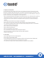
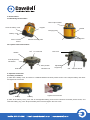
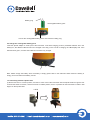
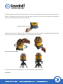
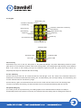
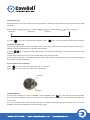
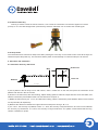
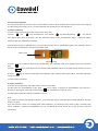
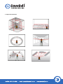
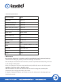
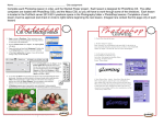
Automatic Leveling Rotary LS560 Automatic Leveling Rotary & Line Laser & Line Laser Instruction Manual (RL4V) Congratulations on your choice of this Contents Automatic Leveling Rotary & Line Laser. For the long-term 1. purpose Features of and Functionsuse of this instrument, we suggest you to read this instruction manual 2. User Safety carefully before using it. 3. Nomenclature 4. Operation Instruction 5. Self-Check and Calibration 6. Application Methods Contents 1. Features and Functions 2. User 7. Safety Technical Specifications 3. Nomenclature 8. Maintenance 4. Operation Instruction 1. Features and Functions 5. Self-Check and Calibration LS 560 automatic-leveling rotary and line laser, can simultaneously project horizontal laser plane, plumb line, and plumb 6. Application Methods up & down laser point. Its extensive functions bring great convenience to set accurate horizontal and vertical and plumb 7. Technical Specifications references for indoors lay out and calibration. This kind of product is featured by easy manipulation and wide applications. 8. Able Maintenance to simultaneously project 360-degree horizontal laser plane, four vertical laser lines, plumb-up and plumb-down points, could formed 4 cross lines in right angle and plumb-up &-down points Vertical laser line could be switched to modulation status, the laser line could be detected by a receiver Laser rotation speed and area scan angle are changeable. Auto leveling, the instrument will make laser flash and alarm sound if beyond tolerance 1. Features and Functions LS 560 automatic-leveling rotary and line laser, can simultaneously project horizontal laser plane, plumb line, and plumb up & down laser point. Its extensive functions bring great convenience to set accurate horizontal and vertical and plumb references for indoors lay out and calibration. This kind of product is featured by easy manipulation and wide applications. • Able to simultaneously project 360-degree horizontal laser plane, four vertical laser lines, plumb-up and plumb-down points, could formed 4 cross lines in right angle and plumb-up &-down points • Vertical laser line could be switched to modulation status, the laser line could be detected by a receiver • Laser rotation speed and area scan angle are changeable. • Auto leveling, the instrument will make laser flash and alarm sound if beyond tolerance • TILT mode has unbalance alarm function, the laser will stop rotating when be hit, to ensures the instrument and ideal working accuracy. • Able to make accuracy self-calibration • Able to realize timed power-off • Able to be operated by remote control • 5/8” screw thread in the center to be connected with tripod 1 • Various accessories of elaborate design can bring usage expansion. • Rainproof and dustproof 2. User Safety • Laser output sign lies near the output aperture. • Do not stare into laser beam directly. • Do not disassemble the instrument or attempt to perform any internal servicing. Repairs and servicing could be performed only by authorized service centers. • The instrument complies with the safety classification standards of laser radiation. 2. User Safety Laser output sign lies near the output aperture. Do not stare into laser beam directly. Do not disassemble the instrument or attempt to perform any internal servicing. Repairs and servicing could be performed only by authorized service centers. The instrument complies with the safety classification standards of laser radiation. 3. Nomenclature 3.1 Main Body Nomenclature Laser output window Keypad Screw of battery cover Charging LED Handle Battery cover 5/8?-11 screw Remote receiving tube Remote receiving tube thread 3.2 Tripodic base Nomenclature Bubble 5/8″-11 screw bolt Lock lever Fine-adjustment handwheel Scale dial Zero-position Adjustable indication line support leg 5/8″-11 screw thread 4. Operation Instruction 4.1 Battery Installation a) Take off the battery cover, and insert 4* C alkaline batteries as below picture shows. Then Snap the battery door back and tighten the lock screw. + Polarity Tighten the lock screw. - Polarity b) Take off the battery cover, put 2 sets of rechargeable battery pack into the instrument as below picture shows, and insert the battery plug. Then Snap the battery door back and tighten the lock screw. 1 Battery plug Rechargeable battery pack Put into the rechargeable battery packs and insert the battery plug 4.2 Charge the rechargeable battery pack Insert the special adapter to outlet jack of the instrument could start charging process. (If alkaline batteries are in the battery box, the alkaline batteries will not be charged in this way.) In the course of charging, the LED displays red. If the LED becomes green, it means the batteries have been fully charged. Note: Please charge the battery when the battery is empty (power LED on the instrument flash means the battery is empty), that could extend the battery use life. 4.3 Connecting with the tripodic base a) Set the lock lever to “LOCK” position, and then it could connect the instrument with the tripodic base through the 5/8’’ screw thread. After connection, set the lock lever to “FREE” position, then it is possible for the instrument to rotate in 360 degree on the tripodic base. LOCK b) Tripod adjusting leg could keep the level position of main unit. Please adjust the legs to center the bubble when use the device. Especially when the laser beam flash and alarm sounds, that mean the device is beyond the self-leveling range and it should adjust the legs to center the bubble.。 LOCK b) Tripod adjusting leg could keep the level position of main unit. Please adjust the legs to center the bubble when use the device. Especially when the laser beam flash and alarm sounds, that mean the device is beyond the self-leveling range and it should adjust the legs to center the bubble.。 Bubble should be centered 2 c) When the lock lever is in “FREE” position, it is possible for the instrument to rotate in 360 degree on the tripodic base, and it also could do the fine-angle adjustment by the fine-adjustment handwheel. 4.4 Connect with the tripod The unit could connect with tripod directly or connect with tripod by the tripodic base 4.5 Keypad Speed setting key Y direction vertical line control / modulate key Area scan key Area shift key X direction vertical line control key Area shift key Slope direction key The unit could connect with tripod directly or connect with tripod by the tripodic base 4.5 Keypad Speed setting key Y direction vertical line control / modulate key X direction vertical line control key Area scan key Area shift key Area shift key Slope key Slope direction key Slope key Power key TILT mode key Remote shield key Modulate LED 3 X direction LED Y direction LED TILT LED Power LED 4.6 Power key Press Power key to turn on the unit. After power on, the power LED will light. The power LED flashing means low power. (After power on, the instrument will enter into the auto leveling status. The rotating speed after leveling is about 500rpm) Note: In the course of auto leveling, all keys are ineffective expect the power key (press these keys without any response)These keys will reactivate after auto leveling. 4.7 TILT mode key a) Press TILT key to enter into TILT mode and the TILT LED will light. In the TILT mode, if the instrument suffers from outside force and become tilted after auto leveling, the TILT LED flashing, the unit stops rotating , the laser flashing and now the instrument will not auto-level any longer. b) Press this key again, the instrument will exit from the TILT mode and then enter into the auto leveling mode. c) Power on and after auto leveling, the instrument will enter into tilt mode automatically after 30 sceonds. 4.8 Speed setting key a) In rotating mode, short press this key, the rotating speed can be switched between 500rpm and 200rpm. b) Extended press this key (about one second), the instrument will stop rotating and the rotating laser will be off. 4.9 Area Scan key a) Press area scan mode key to enter into area scan mode. In area scan mode, press this key to switch the scan angle as follows: Scan in large range scan in middle range (about 60°) (about 30°) scan in small range (about 5°) in just a point (0°) a) Press TILT key to enter into TILT mode and the TILT LED will light. In the TILT mode, if the instrument suffers from outside force and become tilted after auto leveling, the TILT LED flashing, the unit stops rotating , the laser flashing and now the instrument will not auto-level any longer. b) Press this key again, the instrument will exit from the TILT mode and then enter into the auto leveling mode. c) Power on and after auto leveling, the instrument will enter into tilt mode automatically after 30 sceonds. 4.8 Speed setting key a) In rotating mode, short press this key, the rotating speed can be switched between 500rpm and 200rpm. b) Extended press this key (about one second), the instrument will stop rotating and the rotating laser will be off. 4.9 Area Scan key a) Press area scan mode key to enter into area scan mode. In area scan mode, press this key to switch the scan angle as follows: Scan in large range scan in middle range (about 60°) (about 30°) b) Press scan in small range in just a point (0°) (about 5°) key, the scan range will shift clockwise;press button,the scan range will shift counter-clockwise. 4.10 Slope direction key a) Press slope direction key to enter into slope mode. In slope mode, press this key to select the slope direction (X or Y direction) and the relevant LED of X/Y direction will be lighted. b) Press key to adjust the slope angle. (Press once means fine adjustment. Press continuously means quick adjustment) c) Press slope direction key for a long time means exiting from the slope mode. d) The instrument will give a sound alarm when the slope angle is beyond of auto leveling range (laser line flashing and sound alarm indication meanwhile). 4.11 X/Y Vertical line control key Press Press key to turn on/off the vertical laser line of Y direction; key to turn on/off the vertical line of X direction. 4 X direction Y direction 4.12 Modulate key a) At first, the instrument is in the non-modulation mode. Extended press key, LED will light and the instrument will enter into the modulation mode. If the vertical line is already lighted, the detector can detect the signal within the range of 40m. b) In the modulation mode, extended press this key, the LED will extinguish and the instrument will exit from the modulation mode. Here the detector cannot detect any signal. 4.13 Remote shield key This key is used to control the remote function, it can control the instrument to receive the signal from remote (LS312) or not. The LED will light when press this key and then instrument can not receive the remote signal. Y direction 4.12 Modulate key a) At first, the instrument is in the non-modulation mode. Extended press key, LED will light and the instrument will enter into the modulation mode. If the vertical line is already lighted, the detector can detect the signal within the range of 40m. b) In the modulation mode, extended press this key, the LED will extinguish and the instrument will exit from the modulation mode. Here the detector cannot detect any signal. 4.13 Remote shield key This key is used to control the remote function, it can control the instrument to receive the signal from remote (LS312) or not. The LED will light when press this key and then instrument can not receive the remote signal. 4.14 Sleep mode The instrument will be entered into sleep mode after pressing the on/off key on the remote control. Now all the keys are ineffective expect the power key. The instrument will be power off automatically if continuous sleep for 30 minutes. 5 .Self-check and Calibration 5.1 Instrument Accuracy Self-check Vertical line Wall C A B D Platform O C A B D Laser line L=10m a) Set a platform 10m far away from a wall indoors, draw a vertical line on the wall, and place the instrument on the platform with X-axis in face of the wall. b) Power on the instrument, after auto leveling. Adjust rotating speed to make the output laser line clear and visible, and take the intersection point between laser line and vertical line as point A; c) Rotate the instrument by 90°in turn, and after auto leveling, take the intersection points between laser line and vertical line as points B,C,D respectively. 5 d) Measure the distance h between the highest and the lowest point among A, B, C, D; e) If h≤2mm,the accuracy is qualified; If 2mm<h≤5mm, the accuracy is beyond tolerance, and users could calibrate the accuracy by themselves. If h>5mm, the accuracy is beyond tolerance, and please contact authorized servicing centers or dealers for repairs. 5.2 Accuracy Calibration According to the result of accuracy check, mark a reference point O at the position that is h/2 (the center of the highest and the lowest points among A, B, C, and D) lower than the highest point on the vertical line. a) X-axis Calibration 1) Power off the instrument and make X-axis in face of the wall. 2) Press and keys simultaneously, then release key while still pressing key until the line as points B,C,D respectively. d) Measure the distance h between the highest and the lowest point among A, B, C, D; e) If h≤2mm,the accuracy is qualified; If 2mm<h≤5mm, the accuracy is beyond tolerance, and users could calibrate the accuracy by themselves. If h>5mm, the accuracy is beyond tolerance, and please contact authorized servicing centers or dealers for repairs. 5.2 Accuracy Calibration According to the result of accuracy check, mark a reference point O at the position that is h/2 (the center of the highest and the lowest points among A, B, C, and D) lower than the highest point on the vertical line. a) X-axis Calibration 1) Power off the instrument and make X-axis in face of the wall. 2) Press and keys simultaneously, then release key while still pressing key until the LED flashes three times continuously, then the instrument enters into the self-calibration status. Adjust the rotating speed for laser line clearness and visibility. (3) Drop-down the down calibration area cover of LS312 remote control, operate the keypad in the calibration area of remote control to calibrate the instrument as follows steps: Down cover 4) Press Calibration area key to select X direction for self-calibration. The X direction LED on the keypad of the main instrument light. 5) Press key to make laser line move upwards and downwards until it is coincident with the refere nce point O. 6) Press key to confirm the X-direction self-calibration value. Now the laser stops rotation, and X-axis calibration comes to an end. 7) Power off the instrument. b) Y-axis Calibration (1) Power off the instrument, and make Y-axis in the face of the wall. (2) After enter the self-calibration mode, press key to select Y direction for self-calibration. The LED for Y direction on the keypad of the main instrument light, start to calibrate the accuracy of Y axis. 3) Power off the instrument, after the calibration is done. Note: (1) In order to make the last calibration effective, you must power off the instrument after the said calibration, and then power on it again. (2) Y-axis accuracy check is a necessity after X-axis calibration, and X-axis accuracy check is also a necessity after Y-axis calibration. Instrument self-calibration will not be fulfilled until both X-axis and Y-axis accuracy meet the requirement. 6 6. Application Methods 7. Technical specifications Laser wavelength 635nm Laser class ClassⅡ/Ⅲ Horizontal line accuracy ±1mm/10m Vertical line accuracy ± 3mm/10m Plumb-down point accuracy ± 4mm/10m Vertical line angle accuracy ± 3mm/10m Rotary speed 200rpm,500rpm Self-leveling range ±5° Temperature range -10℃ ~+45℃ Area scan angle 60° 30° 5° 0° IP grade IP54 Power 4 x C alkaline batteries or Ni-M H battery pack Low power Power LED flash Size 142×170× 194mm Weight 2.5Kg 8. Maintenance Maintenance •8.As a precision instrument, it should be carefully operated and properly preserved, and any As a precision instrument, it should be carefully operated and properly preserved, and any violent shock or falling violent shock or falling will possibly result in the damage of instrument. will possibly result in the damage of instrument. • Do not attempt to disassemble the instrument, and the unprofessional disassembly will result Do not attempt to disassemble the instrument, and the unprofessional disassembly will result in the damage of in the damage of instrument. instrument. •Keep thethe cleanness window,and andperiodically periodically remove dust by the gentle Keep cleannessofofthe thelaser laser output output window, remove dust by the gentle operation of soft clean cloth or of alcoholic cotton. operation soft clean cloth or alcoholic cotton. Take batteriesout outwhen whenthe theinstrument instrument is is not not in in use use for •Take thethe batteries for aa long longtime, time,and andkeep keepthe theinstrument in the carrying case when it is unused. instrument in the carrying case when it is unused. In despite of waterproof feature, you’d better not use the instrument in rainy days and very humid environment. • In despite of waterproof feature, you’d better not use the instrument in rainy days and very humid environment.