1
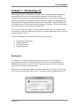
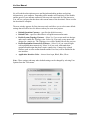
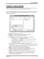
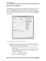
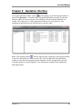
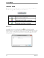
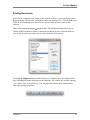
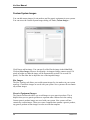
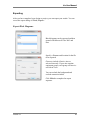
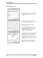
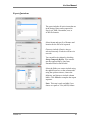
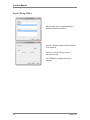
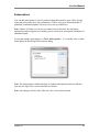
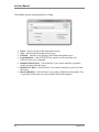
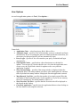
Iris User Manual Version 3.2 Intangi, Inc. 4633 Old Ironsides Drive, Suite 450 Santa Clara, California 95054 www.intangi.com Iris User Manual Notes Version 3.2 Iris User Manual Chapter 1: Introducing Iris............................................................... 1 Starting Iris ................................................................................................................. 1 Chapter 2: System Settings ............................................................. 3 Chapter 3: Topology Interface ........................................................ 5 Topology Toolbar ....................................................................................................... 6 Site Properties............................................................................................................. 7 Path Properties ............................................................................................................ 8 Layers ......................................................................................................................... 9 Design Notifications and Alerts ................................................................................ 11 Chapter 4: Site Design Interface ................................................... 13 Site Design Toolbar .................................................................................................. 14 Catalog ..................................................................................................................... 15 Property Window...................................................................................................... 16 Product Attributes .......................................................................................... 17 Design Workspace .................................................................................................... 19 Connection Window ................................................................................................. 21 Generic Cables .............................................................................................. 22 Templates ................................................................................................................. 23 Creating Templates ........................................................................................ 23 Applying Templates ........................................................................................ 23 Equipment Groups .................................................................................................... 24 Inter-group Connections ................................................................................ 25 Miscellaneous Part Window...................................................................................... 26 Chapter 5: Quotation Interface ...................................................... 29 Quotation Toolbar..................................................................................................... 30 Price Lists ................................................................................................................. 30 Currency Exchange ................................................................................................... 31 Printing Quotations ................................................................................................... 31 Chapter 6: More Features .............................................................. 33 Draw Items ............................................................................................................... 33 Visibility of Objects .................................................................................................. 33 Copy/Paste Configuration Functionality.................................................................... 33 Summary Window .................................................................................................... 34 Working with Stacks................................................................................................. 35 Addon Parts & Services Interface ............................................................................. 36 Printing Documents .................................................................................................. 37 Custom System Images ............................................................................................. 38 Exporting .................................................................................................................. 39 Export Block Diagrams .................................................................................. 39 Export Equipment Lists .................................................................................. 40 Export Quotations .......................................................................................... 41 Export Wiring Tables ..................................................................................... 42 Subscriptions ............................................................................................................ 43 User Options ............................................................................................................. 45 Version 3.2 i Iris User Manual Notes ii Version 3.2 Iris User Manual Chapter 1: Introducing Iris The Iris application is a stand-alone, file-based, Internet-enabled system configuration and quoting tool. Iris is used for the design and quoting of complex multi-vendor systems. Iris is typically used during the proposal process to assist in the site design of a project, including product configuration and connectivity, equipment compatibility, and versioning. Once a design has been completed, Iris will provide a complete, detailed list of equipment and will incorporate the product pricing, if available. You must subscribe to a price list in order to receive and view pricing data. You can use Iris online or offline; if you are using Iris offline, there is a predetermined time limit after which the application will expire. You must login online again to reset the expiration period (7 days). The Iris User Manual is divided into the following main sections. System/Project Definition Topology Interface Site Design Interface Quotation Interface Starting Iris You must have a valid login and password in order to use Iris. By checking the appropriate options below, the application can remember your credentials and also automatically log you in every time. If you forget your password or wish to change it, please visit www.intangi.com/support.htm. Note: If you are running Iris without an Internet connection, the software will remember your login but the auto login will not work. You must provide the matching password. Version 3.2 1 Iris User Manual Iris will read the subscription sources and begin downloading product and pricing information to your computer. Depending on the number and complexity of the models and the speed of your internet connection, this may take some time for first-time users. You will see a progress bar that shows the current status of the download. Please wait for the download to complete. The next window appears for first-time users only and allows you to select some default settings that will affect how Iris behaves when you create new projects. Default Quotation Currency – specifies the default currency. Default Units – specifies either Metric or English measurement units. Enable System Topology Features – Select Yes if you create multi-site designs and want to enable the Topology view. Select No if you only create quotes and designs for a single site. The Topology view will be disabled for all new projects. Enable Equipment Connectivity Features – Select Yes if you create designs with equipment interconnectivity. Select No if you work with stand-alone equipment and designs that don’t require connectivity. Connectivity-related features (such as some toolbar buttons and the Port view) will be disabled in the user interface. Application Interface Color – choose from Aqua, Black, Blue, Silver. Note: These settings and many other default settings can be changed by selecting User Options from the Tools menu. 2 Version 3.2 Iris User Manual Chapter 2: System Settings The System Settings dialog is the initial step used to define a system or project. In this dialog, you can specify the name and a brief description of the project. Note: Using Express Mode, you can skip the System Settings dialog and skip creating a new site. You can start using Iris immediately in the Design View. Later, you can add and edit this information. Label – the label or name of the system. Description – an alphanumeric field for additional information. Country – the country where the system is located Coordinate Type – specifies the method used to enter a site’s location: o No Coordinates – no coordinate system is used. o Lat Long (dd, mm, ss) – latitude and longitude coordinate system using degrees, minutes, seconds format. o Lat Long (dd, ddd) – latitude and longitude coordinate system using decimal degrees format. o UTM – Universal Transverse Mercator coordinate system. Global Quadrant – specifies the appropriate global quadrant. The four quadrants are Northwest, Northeast, Southwest and Southeast. The North/South divide is the equator and the East/West divide is the Prime Meridian. Datum – reference datum for the selected coordinate system. Units – defines what type of units will be used throughout the project. This selection will apply to both linear and mass measurements. Currency – specifies the default currency that will be used in the quotation Properties – displays properties that have been defined for the project. The properties may be on more than one tab and some properties may require a selection prior to closing the dialog. Version 3.2 3 Iris User Manual Notes 4 Version 3.2 Iris User Manual Chapter 3: Topology Interface The Topology Interface defines the high level topology of the network you are designing. This interface allows you to manage the sites and paths in the network. Of course, features like Sites and Path are only available if you have enabled Topology features in User Options. This chapter is divided into the following sections: Topology Toolbar Site Properties Path Properties Site/Path Properties Tab To add a site, select Site|New from the menu or right click and select New Site. To add a path, select Path|New from the menu or right click and select New Path. Version 3.2 5 Iris User Manual Topology Toolbar The Topology toolbar allows quick access to the commonly used topology functions. The table below provides a brief description of each button. Button Description Opens the system settings window to create a new system Opens the open system/project window dialog Saves the currently open system Opens the master print dialog Opens the System Settings dialog Opens the Quotation window. The currency symbol dynamically changes based on the selected currency of the system. Opens the Configure Addon Parts & Services interface Opens the Summary Window * Opens the Site Design window for the selected site * Resets to no zoom * Enables “zoom in” functionality Opens the Layers window Opens the Design Messages window and displays validation messages. * These buttons are unavailable if topology features are disabled in System Settings. 6 Version 3.2 Iris User Manual Site Properties The Site Properties dialog defines various aspects of the site including its location and contact information. Name – name of the site/pop/node/data center. Layout Location - Depending on whether coordinates were selected in the system window, this will determine whether the layout location is enabled or not. In this case, No Coordinates was selected, therefore, layout location information is not needed. Type – a collection of images from which you can select to represent your site. Address – enter the address where the site is located. Contact – enter the contact for the site. Description – allows you to write any comments or notes for the site, such as a backup contact person, access information, etc. Version 3.2 7 Iris User Manual Path Properties The Path Properties dialog defines various aspects of the path including its endpoints and path length. Site A – select the first site you wish to connect. Site B – select the second site you wish to connect. Path Length – automatically calculated based on coordinates of the endpoints or user specified if either end site is non-coordinate based. Type – specifies the path or link type with options including microwave, leased line, fiber optic, ISDN, etc. The Swap Endsites button will automatically reverse the path. For example, path A to B, when swapped, will become path B to A. Note: A valid path must have two sites and the two sites may not be the same. 8 Version 3.2 Iris User Manual Layers The layers function allows you to segregate sets of equipment and connections into groups. These groups or layers can then be used to provide separate quotes depending on the active layers. The Layers dialog is accessed from the main menu under the Tools option or by clicking the button. The Layers dialog allows you to specify up to 32 layers. To add a layer, simply select an open slot or row and type in the layer name. Clicking on the Active column will toggle the layer from active to inactive. Once layers have been defined, individual equipment or connections can be placed into one or more layers as appropriate. To place equipment into a specific layer, right-click on the equipment and select the Layer Membership item. This will display the list of currently defined layers with a check next to the layers that the equipment is a member of. You can change the membership by selecting the layer name. Version 3.2 9 Iris User Manual Note: To modify the layer membership of multiple items, select all the items and then right-click to apply the layer setting to all of the selected items. You can also change the membership of equipment and connections site-wide by right-clicking on the site in Topology View. Any equipment that is not a member of an active layer will be displayed in gray or with gray text to distinguish its state. Equipment that is not active will not be included in the equipment list or quote. Note: Equipment added to the design is automatically placed into the currently active layers. 10 Version 3.2 Iris User Manual Design Notifications and Alerts The software automatically notifies the user if there are any errors, warnings, info messages or recommendations at the equipment, site and system levels. The Design Messages window can be accessed by clicking the button on the Topology or Design Window toolbars. The icon will change if the software detects the following conditions: Errors, Warnings, Recommendations, and Info messages. You can browse the different messages by selecting them on the left pane. This will display more detailed information about the message. By clicking on More Information, you can go to an external link or document for reference. Click Go To Item to bring the particular product or site that contains the message into focus. In the topology view, system-level errors are signified by a pink background. Sites containing errors will be highlighted in red. At the site view, site-level errors are signified by a pink background. Equipment containing errors will be highlighted in red, as shown below. Version 3.2 11 Iris User Manual Notes 12 Version 3.2 Iris User Manual Chapter 4: Site Design Interface The Site Design Interface or window is the main tool used for the creation of the design for a specific site. Access the design window by double-clicking on a site in the topology view, or you can select the site and click on the Site | Site Design Window menu, or right-click and select the Site Design Window menu. Catalog Property Window Site Design Toolbar Design Workspace Note: If you have disabled topology features in User Options, then the design workspace will include the New, Open, Save, Print, Print Preview, Quote and Layers buttons along with the Design Toolbar buttons. This chapter contains the following sections: Site Design Toolbar Catalog Property Window Design Workspace Connection Window Templates Equipment Groups Miscellaneous Part Window Version 3.2 13 Iris User Manual Site Design Toolbar The Site Design toolbar provides quick access to the commonly used site design functions. The table below provides a brief description of each button. Button Description Changes the view from Block, Port*, Rack and Equipment List Opens the Quotation window. The currency symbol dynamically changes based on the selected currency of the system. Opens the Configure Addon Parts & Services interface Opens the Summary Window Previews the current view or other documents Copies the selected items Pastes the last copied items Deletes the selected items Creates a new template using the currently selected items Displays a selection of templates to choose from. The selected template will then be applied. Switches to the Connection Tool * * Highlights connections based on signals or application protocols Displays the product documentation for the selected equipment Opens the Equipment Group dialog Switches between Equipment Groups defined for this site Opens the Design Messages window and displays validation messages. Displays a drop-down menu of available Advisor models * These buttons are unavailable if connectivity features are disabled in System Settings. 14 Version 3.2 Iris User Manual Catalog The Catalog window displays and allows access to all the models defined for use in your designs. The Catalog also displays your Favorites and allows you to search for a product. The Advisors tab will list any available Advisor models. The Templates tab will list any available manufacturer published templates. In the Catalog tab, you can select the item you wish to use in your design. Simply double click on the item and it will be displayed in the design workspace. You can also dragand-drop items from the Catalog directly onto the design workspace. The Favorites tab keeps a list of your favorite items for easy access. To place an item in Favorites, select the item, right mouse click and select Add to Favorites. To remove an item from Favorites, select the item, right mouse click and select Remove Favorite. You can also add custom nested folders by right clicking in Favorites. Right clicking on a folder provides options to edit or delete the folder. To move items between folders, right click on the item and select Edit Favorite. The Search tab allows you to quickly search for products in the Catalog. To search for a product, enter a term in the box and click the Search button. The search results will be displayed below. A product will match if the search term is found in the label, part number, manufacturer name, or product keywords. You can right mouse click inside the Catalog or Properties window to see discontinued products or product options, if available. The EOS icon (“End of Sale”) will appear next to the discontinued products inside the catalog. Discontinued product options will display the inside the Properties window. Version 3.2 15 Iris User Manual Property Window The Property window displays properties that are associated with the currently selected equipment. The Property window allows you to modify a product’s properties to meet your design goals. As you make changes in one property, other properties may change due to configuration rules built into the product models. The drop-down list located above the property list will appear whenever a product contains plugin modules. By selecting a plugin in the drop-down list, you will be able to modify that plugin’s properties. The box immediately below the property list will display any messages that are associated with the currently selected property. Icon Meaning Property is required and a selection or entry must be made Property is locked and cannot be changed by the user Property or property option is discontinued or End of Sale More information is available The Property Window may also contain other tabs such as: 16 Ports – displays a drop-down list with the ports on the equipment. By selecting a port in the drop-down list, you will be able to modify that port’s properties. Accessories – displays a list of recommended accessories for the equipment. You can add accessories to your design by clicking on the checkbox next to each item. Spares – displays a list of recommended spares for the equipment. You can add spares to your design by clicking on the checkbox next to each item. Attributes – displays a list of attributes for the equipment as well as the Quantity Multiplier property. Version 3.2 Iris User Manual Product Attributes There are default attributes that all models have, but sometimes they might be hidden depending on how the model was created. They are found in the Attributes tab. Quantity Multiplier – Specifies the number of exact copies of the product. Create Stack – Select TRUE to convert the quantity to a stack. See Chapter 6. Status: Specifies the item’s status (include, exclude, or reuse in the quotation). The status property helps designers to create real-life scenarios on the workspace (that includes existing and 3rd party equipment) and then quote them accordingly. Only those items set to be proposed or optional will be included in the quotation. o Proposed – proposed items are included in the quotation. This is the default option for new items placed on the design workspace. o Optional – optional items are included in the quotation; however, their line item numbers will be appended with OPT. o Existing – existing items are excluded from the quotation. o Future – future items are excluded from the quotation. These items are included in the design and may be quoted at a later time. o 3rd Party – 3rd party items are excluded from the quotation. o Reuse – reuse items are excluded from the quotation. Reuse items are special because their parts can be salvaged by new items that use the same part numbers. The quantity of any salvaged part will be reflected in the quotation. For example, if a new equipment requires two plugins but there is one that can be reused, then the quotation will only show one plugin. o Per Parent – this option is only available for children and plugins; they will adopt their parents’ status. ID # – Automatically generated unique ID number for similar items. Extended Label – Enter a descriptive label (optional). This label is limited to 48 characters and will appear below the main label for the equipment. Mounting – Specifies how the equipment is mounted. o Unknown – there is no mounting specified. o Desktop – desktop mounting. o Floor – floor mounting. o Wall – wall mounting. o Outdoor – outdoor mounting. o Racked (auto) – the equipment is racked automatically. o Racked (edge) – the equipment is placed to the left or right edge of the rack. o Racked (center) – the equipment is centered horizontally in the rack. Version 3.2 17 Iris User Manual Height/Width/Depth – These are the dimensions of the product. Height (RU) / Height Capacity (RU) – For equipment, the height in Rack Units; for racks, the capacity of the rack. Power Consumption – The total power consumption of the selected product or plugin. The Attributes tab for racks also displays the total power consumption for the entire rack including racked items. Heat Dissipation – The total heat dissipation of the selected product or plugin. The Attributes tab for racks also displays the total heat dissipation for the entire rack including racked items. Weight Installed – The weight of the product when it is installed. The Attributes tab for racks also displays the total installed weight for the entire rack including racked items. Weight Shipping – The shipping weight of the product. The Attributes tab for racks also displays the total shipping weight for the entire rack including racked items. Note: The last four attributes are additive to the selected chassis or plugin level. For example, the weight of the chassis will include the weight contribution of all its plugins. 18 Version 3.2 Iris User Manual Design Workspace The Design Workspace is where you create and modify the configuration or design for the respective site. In the Design Workspace, you can do the following main tasks: Add equipment from the Catalog. Select equipment for configuration in the Property Window. Make connections between equipment and to other sites. Add draw items and annotations to the design. View your site network design in Block, Port, or Rack Views: o Block View – presents a high-level network design, as pictured above. o Port View – presents a port diagram that shows the available ports on each equipment. Connections between equipment are shown emanating from their respective ports. In this view, you can make connections by clicking and dragging between individual ports without opening the connection window. The Port View also supports the concept of expanding and collapsing of ports. If Collapse Ports is selected, all ports that are in the same port group will collapse and only one port will be displayed. If Expand Ports is selected, then all ports will be displayed. Version 3.2 19 Iris User Manual o Rack View – presents a rack diagram showing where equipment is racked. In the Rack View, the far left is the equipment holding area. The scale to the left is measured in Rack Units (RU). To rack an equipment, click and drag the equipment from the holding area and move it onto a rack. The equipment will snap into place on the rack. If the drop location is not large enough to accept the equipment, the equipment will snap back to the holding area. You can move an equipment out of the holding area by placing it on a rack or by changing the equipment’s Mounting property and then dragging it to the desired location. In the Rack View, you can hold the Shift key while moving and dropping an equipment to set its mounting property to Floor mounting. Other Views – There are other views that may appear depending on the products in your design. These views will show the supply and demand of various “consumables” for the equipment and also the flow of the “consumable” among the various elements in the design. For example, the PoE View will appear when working with PoE equipment and will show the PoE consumable value for each equipment and flow values for each connection. 20 View the equipment list for your network design. This provides the equipment list or bill of materials for all the equipment you have added in the design window including any spares or accessories. The list also contains items that have been automatically added based on property selections and connections between equipment. You can add “miscellaneous” items to the list by right clicking and selecting the Add Misc Part menu. This feature is discussed later in this chapter. Visually explore the signal and application (protocol) flows in the design. This is accomplished by using the filter drop-down located on the toolbar. When a signal or an application protocol is selected, the appropriate connections on the work surface are highlighted in green while the remaining connections are shown in a light gray. In the case when a signal is selected, any connection carrying that signal is highlighted and in the case of an application protocol, any connection that supports the selected protocol is highlighted. Version 3.2 Iris User Manual Connection Window The connection window is displayed when you use the connection tool to connect two equipments together. The connection window allows you to select the specific ports on each equipment for the desired connection. To create a connection, select one port on each side, specify a connection type (optional), specify a length and quantity, then click Make Connection to connect the two ports. Incompatible ports are highlighted in red. Connection Type – When two compatible ports are selected, the connection type area will display the available signals and/or connection options. The application can auto select the connection type for you. Length – the length of the desired connection cable to be used to connect the two equipments together. The actual cable may be longer then the length specified. Quantity – the number of connections to make between the two equipments. If a port group has multiple linked ports, you can select the port group and select the quantity of connections you want. The quantity drop-down lists up to the maximum allowable. Icon Meaning Port is available Port is selected Port is already connected Port is available but not compatible Version 3.2 21 Iris User Manual When making port to port connections in port view, a mini connection window will display. Select the connection type, specify a length, and press Enter to make the connection. Alternatively, you may double click on the connection type to complete the connection. Generic Cables In the case where your parts list does not contain any cables that fit the parameters of the connection type, the application will automatically create a cable and add it to the equipment list. The resulting generic cable has a description that contains the specifications and connectors that match the connection type selected. To change how the application handles generic cables, go to the User Options menu under Tools. 22 Version 3.2 Iris User Manual Templates The templates feature allows you to create re-usable designs or design fragments. These templates are saved as files and can be shared with other users. Creating Templates You can create a template by selecting the equipment, draw items and connections for your template and clicking on the button on the toolbar. You may also right click and select Create Template menu option. The following Save As dialog will be displayed. Add the following unselected items to the template – Racks containing selected equipment – automatically adds any racks that the selected equipment are mounted on. Equipment mounted on selected racks – if a rack is selected, will automatically add all equipment on the rack. Connections between selected equipment – will automatically add all connections between equipments that are selected. Connections between selected equipment and non-selected equipment are not included in the template. Applying Templates To apply an existing template, click on the button on the toolbar. This will display the last templates that you have applied and will also display an Other… menu option. Selecting one of the recently used templates will automatically apply that template. Selecting the Other… menu will open the Open File dialog that will allow you to select a saved template. Select a template and click the Open button to apply the template. Version 3.2 23 Iris User Manual Equipment Groups The Equipment Group feature allows you to manage sites with a large number of equipment. You can use Equipment Groups to break up a site into multiple work areas or views where you can design without the clutter. These work areas can also be printed on separate sheets to improve the documentation. Access Equipment Groups by clicking on the button on the toolbar. In this window you can add and remove Equipment Groups. You can also specify which groups you want printed when printing the site design documents. The Combine Connection Labels option allows you to specify how connections between groups are displayed. The At Group Level option will combine all connections leading to another group under one connector label. The At Equipment Level option will combine all connections leading to each equipment at another group under a separate connector label. Note: The combine connection label setting applies to all groups at the site. You can switch between equipment groups at a site by selecting the group in the Equipment Group drop-down located on the toolbar. The equipment group functions are available only in the Block and Port Views. The Rack and Equipment List Views are composite views containing equipment from all groups. Note: Iris version 3.1 has eliminated Sync’d Groups in lieu of the more powerful stacks feature. 24 Version 3.2 Iris User Manual Inter-group Connections Connections between groups are made by right clicking on an equipment and selecting Connect on the menu. This will open a modified connection dialog that will allow you to select the endpoint group and equipment as shown below. This diagram shows how connections between groups will be displayed. You can also make connections between groups by using the connect tool and connecting an equipment and an existing group connector. This will open the Connection dialog with the endpoint group, pre-selected. Version 3.2 25 Iris User Manual Miscellaneous Part Window The Miscellaneous Part window allows you to add parts to the equipment list. The added parts can come from the built-in list of parts in the database, or you can add a generic part. To access the Add Misc. Part window, right click on the Equipment List window and select the Add Misc Part menu item. You can also access the dialog through the Edit menu. To edit or delete a miscellaneous part, right click on the part and select Edit Misc Part or Delete. The Add Misc. Part dialog is divided into two sections: 26 Part Detail – information about the part that is to be added to the equipment list. If a part is selected from the Parts Catalog, then the Part Number, Description, and Manufacturer will automatically get generated. o Optional – select if this part is to be defined as an optional part in the equipment list. o Generic – check this box if the part is not in the parts database. If checked, you must manually enter the Part Number, Description, Manufacturer as well as pricing information. o Part Number – displays the part number. o Description – displays the part description. o Quantity – specifies the part quantity. Version 3.2 Iris User Manual o Associate This Part With – specifies an optional equipment that this part will be associated with. By associating this part with another equipment in the quote, you are making a link such that if that equipment is deleted, the added part would be automatically deleted as well. o Show As Subline – specifies that this part should be shown as a subline of the equipment selected in the “Associate This Part With” drop-down. o Manufacturer – specifies the manufacturer of the part. Site(s) – all sites that are associated with this project will be listed. If the part needs to be added to multiple sites, click on the Add to Multiple Sites button and check the appropriate sites. Note: When applying to multiple sites, the associate with equipment function will only work for the current site. No associations will occur at the other sites. Miscellaneous items will display the Version 3.2 icon in the Equipment List view. 27 Iris User Manual Notes 28 Version 3.2 Iris User Manual Chapter 5: Quotation Interface Access the Quotation window via the on the Topology or the Site Design toolbars or select File | Quotation… from the menu. The Quotation window provides a read-only interface where you can view quote views and prices for the system design that was created. The Composite View lists equipment at all sites. You can choose to view equipment at individual sites by clicking on its respective label. Note: The Quotation button will only appear on the Topology or Site Design toolbars if you have subscribed to at least one price list. You can right click in the Quotation window to copy the entire quotation to the clipboard. Or you can right click a specific row and copy the row to the clipboard. You can paste the contents of the clipboard to other applications. Version 3.2 29 Iris User Manual Quotation Toolbar The Quotation toolbar provides quick access to the commonly used quotation functions. The table below provides a brief description of each button. Button Description Opens the System Settings dialog Opens the Price Lists dialog Allows add or edit of currency exchange rates Previews the current quotation Exports and saves the quote as an Excel file Price Lists Access the Active Price Lists dialog by clicking on the toolbar. All available, published price lists are listed for each vendor. Select a vendor, click Edit, and then select the price lists that are appropriate for your quotation and click OK. Your selections apply to this quote only. You can click on the checkbox to remember these price lists for any new systems you create. 30 Version 3.2 Iris User Manual Currency Exchange Access the Exchange Rate window by clicking on the toolbar. If available, vendorpublished exchange rates ( ) are listed and automatically applied. To enter your own rate, click Add. Specify the currencies you are converting from/to using the drop-down list and enter an exchange rate. The prices in the quote will update automatically. The Source column specifies the vendor that published that rate. User-defined rates will show “user”. Printing Quotations First, select the site you would like to print on the Site List window. You may choose the Composite View or an individual site. Then, click on to see a print preview and then click the Print button to specify which page(s) to print. Version 3.2 31 Iris User Manual Notes 32 Version 3.2 Iris User Manual Chapter 6: More Features Draw Items Simple vector drawings and annotations (text boxes) can be added to the Block, Port and Rack views. Drawings consist of basic elements that can be grouped together. Add a draw item to the workspace by clicking the Draw menu and selecting Line, Triangle, Rectangle, Oval, or Text Box. Then select and double click the item to display its Properties window. Multiple draw items can be edited simultaneously, grouped, and aligned. Single draw items can be rotated and ordered. Once you create a grouped draw item, it behaves as a single draw item. You can select multiple items by lasso selecting or by holding the CTRL key while selecting the items. Text annotation is added via the Text Box. Text can also be added to any draw element except for Line items. Double click on the Text Box to edit the text. Note: You can select equipment and draw items when using the Align function. Visibility of Objects Hiding objects can help you reduce the clutter on the workspace. You can specify if an object is displayed in the Block/Port View and Rack View. Right click an object on the design workspace and select Show In View and check/uncheck Block/Port View and Rack View. To show hidden items, right click on the background of the workspace and select Show Hidden Items. Note: Items that have connections, racks, and racked objects cannot be hidden. Copy/Paste Configuration Functionality You can copy and paste the configuration of an entire product or an individual plugin module. To copy the configuration of a product, right click on the item and select Copy Configuration. To paste the configuration, select one or more target products, then right click and select Paste Configuration. To copy and paste the configuration of a plugin module, select the module from the dropdown list. Right click on the plugin’s property window and select Copy Configuration. There are two ways to paste the configuration to other plugins. You can select another compatible plugin from the drop-down list, then right click and select Paste Configuration. Alternatively, you can select one or more products and Paste Configuration. The plugin’s configuration will be copied to all similar plugins across the selected product chassis. Version 3.2 33 Iris User Manual Summary Window The Summary Window provides a read-only display of the different ports, slots, modules/transceivers, accessories, and spares of the selected equipment or sites. You can access the Summary Window by clicking on the Design toolbars. button in the Topology or Site The Ports tab displays the total number of port types in the selected equipment or sites. Used ports are ports that have been connected. Open ports are still available to be connected. The Slots tab displays the total number of slot types in the selected equipment or sites. Used slots are slots that are occupied. Open Slots are still available for modules and transceivers to be slotted. The Modules/Transceivers tab lists the quantities of all the different types of modules and transceivers in the selected equipment or sites. The Accessories tab lists the quantities of all the different types of accessories in the selected equipment or sites. The Spares tab lists the quantities of all the different types of spares in the selected equipment or sites. You can right click on each of the tabs to copy the contents to the clipboard. 34 Version 3.2 Iris User Manual Working with Stacks Stacks are a convenient way to work with many identical items but without cluttering the design workspace. For example, you can create a stack that consists of 100 IP phones that are represented by one object on screen. All the items in the stack have synchronized configurations, but they retain their individual ports, connectivity, and rack view (if applicable). Connections to a stack differs slightly from regular connections. The Connection window displays all the ports from all members of the stack. You can select First Available or double click on the port to drill down to a particular port on any stack unit. You can make multiple connections to the stack at the same time. The default behavior is to connect ports sequentially using all compatible ports on the first stack unit, followed by the second unit, etc. You can select Interleave stack ports to change the connection sequence as shown below. The attributes of a stack object show both the individual and power and weight values and the totals for the stack. If the stack participates in a consumable view (for example, PoE view), the stack will display a composite value based on the calculated total of the stack units. Version 3.2 35 Iris User Manual Addon Parts & Services Interface The Addon interface gives you a ‘heads-up’ view of all addon parts and services available or currently configured on all equipment in a specific site, or even multiple sites, simultaneously. Addon parts can consist of accessories, spares, and services that are associated with the equipment in the design. There are several ways to access the Addon interface. The Addon icon appears in the Topology toolbar and the Site Design toolbar. You can also access the interface by rightclicking in any design view or the topology view and selecting “Configure Addon Parts & Services.” The Addon interface is also accessible through the menu. The icons, menus and right-click menus will only appear if addon parts and services are offered and available to configure. A drop-down list will appear in the upper right corner if addon parts and services are available for more than one manufacturer. Select the appropriate manufacturer to see that manufacturer’s addons. Parts are added to the design by ticking the appropriate checkboxes or selecting the option from the drop-down list. If you make a mistake, you can uncheck any box or select the blank from the drop-down list, thus removing the selection. As you make selections, the corresponding parts are added to the Summary section of the interface. Checking the “Not Needed” option has the same effect as not selecting any addons for a particular row; it indicates that addons were considered and determined as not needed. Checking, then unchecking, the “Not Needed” option is also a quick way to clear all selections for a specific row. Various options are also available when you right click on the Addons interface. The Status of an addon part or service defaults to the parent item’s status. For example, if the parent item’s status is Optional, then the addon status will also be Optional. To change the status of the selected addon to be different than the parent status, right click on the checkbox and select “Force Proposed” or “Force Optional”. Select “Per Parent Status” to restore the default behavior. Some manufacturers recommend addon parts or services to be automatically included with the parent item. When “Auto Select” is enabled, the icon will appear and the row will display a green hatched pattern. Selecting any other addon will disable this option. Right click and select “Auto select recommended” to re-enable the recommended addon. If you want to freeform select any number of addons in a particular row, right click and select “Unlocked selection mode”. Unlocked rows will be displayed in a red hatched pattern and will show an unlocked icon. 36 Version 3.2 Iris User Manual Printing Documents After you have completed the design of your system or project, you can print the results. Before printing, select the site you want to print in the topology view. You can hold down CTRL to select multiple sites. If no sites are selected, then all Active Sites will be selected. Then, click on the print button on the toolbar. The Main Print dialog allows you to choose which documents to print, to collate the documents by site, to include all active sites or only selected sites, and to preview the documents to be printed. The Copy to Clipboard button on the Print Preview Toolbar copies the contents of the page excluding the header and footer to the clipboard. The content may include topology view, chassis view, rack profile, etc. You can paste the contents of the clipboard into other applications as a picture. Version 3.2 37 Iris User Manual Custom System Images You can add custom images for site markers and for generic equipment in your systems. You can access the Custom System Images dialog via Tools | Custom Images... Click New to add an image. You can specify a label for the image in the Label field. Click on Select Image to browse for an image. An imported image cannot exceed 150 pixels in height or width (the image will be automatically resized if it exceeds 150 pixels). Use the slider bar to adjust the size of the imported image. Site Images The Site Topology tab allows you to add custom images for site markers in your system topology. Custom site images are saved with your system. New systems will not contain any custom images. Generic Equipment Images The Generic Product tab allows you to add images to your generic products. This is helpful when you use generic products to represent other vendors not in the catalog. Custom generic product images are saved with your system. New systems will not contain any custom images. When you create a template that contains a generic product, any generic product custom images are also saved in that template. 38 Version 3.2 Iris User Manual Exporting After you have completed your design or project, you can export your results. You can access the export dialog via Tools | Export... Export Block Diagrams Block diagrams can be exported and then opened with Microsoft Visio 2003 and later. Specify a filename and location for the file to be exported. Choose to include all active sites or selected sites only. If your site contains equipment groups, each group will have its own tab in Visio. You can exclude the background and exclude connection labels. Click Finish to complete the export sequence. Version 3.2 39 Iris User Manual Export Equipment Lists Equipment lists can be exported in Excel, raw XML, RosettaNet, text, or xCBL file formats. Select format and specify a filename and location for the file to be exported. Choose to include all active sites or selected sites only. You can add a site column by checking Group Composite By Site. You can also sort the exported list by Line Item, Extended Label or Rack Label. Select the fields you want to include using the right/left arrows, set the column order using the up/down arrows, choose the delimiter, and choose to include column labels. Click Finish to complete the export sequence. Note: This step is only available if you choose to export to Text (ASCII) format. 40 Version 3.2 Iris User Manual Export Quotations The quote includes all active items that are in the design. Data can be exported in Excel, raw XML, RosettaNet, text, or xCBL file formats. Select format and specify a filename and location for the file to be exported. Choose to include all active sites or selected sites only. Each site will have its own tab. You can add a site column by checking Group Composite By Site. You can also sort the exported list by Line Item, Extended Label or Rack Label. Select the fields you want to include using the right/left arrows, set the column order using the up/down arrows, choose the delimiter, and choose to include column labels. Click Finish to complete the export sequence. Note: This step is only available if you choose to export to Text (ASCII) format. Version 3.2 41 Iris User Manual Export Wiring Tables Wiring tables can be exported and then opened with Microsoft Excel. Specify a filename and location for the file to be exported. Choose to include all active sites or selected sites only. Click Finish to complete the export sequence. 42 Version 3.2 Iris User Manual Subscriptions You can add subscriptions to receive product information (models, parts, cables, design rules) and pricing data (price lists, promotions). If there is any new information that is published, an automatic update will occur every time you launch Iris. Note: Updates will only occur if you are connected to the Internet. Not all product information and pricing data are available; please contact your subscription distributor for additional details. Access and manage subscriptions via Tools | Subscriptions… You can add, edit, or delete subscriptions in the Manage Subscriptions dialog. Note: The subscriptions with the blue flag are default subscriptions which are linked to your specific login. They can be edited but not deleted. Note: Any changes will only take effect once Iris is closed and restarted. Version 3.2 43 Iris User Manual Click Add to open the Subscription Source dialog. 44 Label – specify a name for this subscription source. Type – specifies the subscription source type. Location – enter the url or directory path of the subscription source. Login Required – If the FTP/HTTP site requires an Account Name and Password, enter your credentials. Include Products/Parts – Check this box if you want to subscribe to product models and parts from this source. Include Price Data – Check this box if you want to subscribe to price lists from this source. Inactive/Disabled – Check this box if you want to disable this subscription. This is especially useful when you want to disable default subscriptions. Version 3.2 Iris User Manual User Options Access Iris application options via Tools | User Options… General tab Application Color – select from Aqua, Black, Blue or Silver. Automatic Login – specifies if Iris will remember your user credentials and login automatically. If you are running the software without an Internet connection, you must enter your password and Iris will not automatically login. Proxy Login – specifies if Iris will remember your proxy credentials and login automatically. Subscription Checks – specifies how often subscriptions are checked for updates. You can specify if checks should occur every time the application starts or once every day. By default a check for updates occurs every time the application is started. Show Startup Dialog – specifies if the startup window is displayed when the application starts. The startup window provides a quick launch point for common tasks. By default the startup window is displayed when the application is started. Most Recently Used List – specifies the number of previously opened files that will display in the Recent Files menu. Set the number to 0 if you do not want any files to be remembered. The default number of files is 10. Show Favorites Tab First – specifies that the Favorites tab will be displayed as the first tab in the Catalog. Close/Exit Application – specifies how the application behaves when clicking on the close button or selecting the exit menu. Version 3.2 45 Iris User Manual New System Defaults tab Default Country – specifies the default country that will be used for new systems. Select [no selection] if you want to choose the country for each new project you create. Default Currency – specifies the default currency that will be used for new quotations. Select [no selection] if you want to choose the currency for each new project you create. Default Units – specifies either Metric or English measurement units. Select [no selection] if you want to choose the units for each new project you create. Default Coordinate Type – select No Coordinates as the default or [no selection] to choose the coordinate type for each new project you create. Enable Topology – select Yes to enable topology features like the Topology View, Sites, Paths, etc. Select No to disable topology features. Enable Connections – select Yes to enable connectivity features like the Connect Tool, Application Protocol browser, Wiring Table, etc. Select No to disable connectivity features. Design tab Initial Design View – specifies the initial view when opening a site. Grid Spacing – specifies the grid spacing on the Design Workspace. Enable Snap To Grid – specifies that objects will snap to the grid on the Design Workspace. Show Grid On Screen – specifies a visible grid on the Design Workspace. Paste Accessories/Spares – specifies how paste configuration will handle accessories and spares. When pasting a configuration that contains accessories and/or spares, this setting determines if the paste should Always or Never include those items. You can select Ask me each time if you would like to be prompted each time. The default setting is to ask whenever a past configuration includes spares or accessories. Mirror Generic Product Ports – specifies if port mirroring is enabled for connections between generic and standard equipment. When enabled, the generic equipment's port and auto-cabling will be determined by those ports. You will be prompted to manually select a cable if mirroring is disabled. Mirroring will not apply to connections between generic equipment or connections to path connectors. Port mirroring is enabled by default. Use Generic Cables – specifies whether generic cables are available for use in the application. Auto-number Equipment – specifies if equipment auto-numbering is enabled. Auto-numbering appends a number to the item label for ease in tracking identical items. Auto-numbering is enabled by default. Heat Dissipation Unit – specifies the units for heat dissipation. 46 Version 3.2 Iris User Manual BOM/Quotation tab Quote Generic Cables – specifies whether generic cables appear in the quotation. All generic cables will have a zero price. This option is set to No and disabled if the Use Generic Cables option is set to Never. Generic cables are excluded from the quotation by default. Flat BOM/Quotation – specifies how the quotation and Bill of Material will appear. The default setting is a hierarchy with mainline and subline items. The Flat BOM/Quotation groups the items by part number and quantity. Excel Discount Column – specifies if the discount column in an exported quote should be formatted as a percent or a value. Export Sort Type – specifies the sort option for line items in the exported equipment list or quotation. You can select to sort by line item number, extended label, or rack label. By default the exported line items are sorted by line item number. Note: This option only applies when exporting in Excel, rawXML, and Text formats. Export Group By Site – specifies if the exported equipment list or quotation will be grouped by site. When grouping by site, a "SiteName" column will be added to the exported data. By default, exported quotation line items are not grouped by site. Note: This option only applies when exporting in Excel, rawXML, and Text formats. Version 3.2 47