1
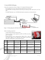
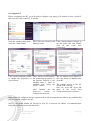
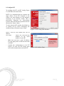
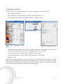
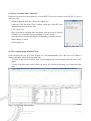
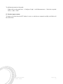
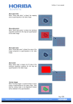
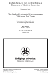
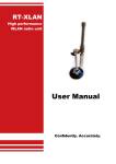
RT
Quick Start Guide
Version:
Author:
Owner:
121005
Paris Austin
Support
List of contents
1. Introduction................................................................................................................................. 1
2. Install RT Software ..................................................................................................................... 1
3. Install RT-Strut (Optional) .......................................................................................................... 2
4. Install RT-UPS (Optional) ........................................................................................................... 2
5. Installing the RT ......................................................................................................................... 3
5.1. With the RT-Strut: ................................................................................................................ 3
5.2. Without the RT-Strut: ........................................................................................................... 4
6. Installation of GPS Antenna/s...................................................................................................... 5
7. Connect RT/RT-UPS/Laptop....................................................................................................... 6
8. Configure RT .............................................................................................................................. 7
9. Initialisation of the RT ................................................................................................................ 9
10. Run a Test and Collect a Data Set ............................................................................................ 10
11. Plot a simple graph using RT-View ......................................................................................... 10
12. Further improvements ............................................................................................................. 11
1. Introduction
This guide can be used to install and configure your RT Inertial and GPS Navigation System and
RT-Strut (optional) for basic use. This guide has been written using an RT3000 as a demo unit. The
guide applies to all RT2000, RT3000 and RT4000 products. Connections for the RT2000 series are
different but features are the same. For more detailed instructions, refer to the manual for each
product.
2. Install RT Software
To view data being collected in real-time, you need to run the software supplied with your RT. To
install the software:
–
Insert the CD provided into your PC
–
Run the setup program:
RTsetup.exe (Figure 1)
–
Follow the on screen instructions given by the installer
Figure 1. RTSetup in Explorer
RT Quick Start Guide
Version: 121005
Page 1/11
110608
3. Install RT-Strut (Optional)
The RT-Strut is used to mount an RT quickly and securely in a vehicle. By using an RT-Strut the
RT is able to accurately measure the motion of the vehicle.
Follow these steps to install the RT-Strut into the vehicle:
–
Attach the extension legs to the base of the RT-Strut
–
Shrink the RT-Strut to its minimum height by opening the
middle lever on the telescopic pole
–
Position the RT-Strut in the vehicle
–
Compress the spring by raising the spring lever (Figure 3)
–
Extend RT-Strut length so the pad pushes against the roof
–
Lock the telescopic pole by closing the middle lever
–
Lower the spring lever to release the spring (Figure 4)
–
Check the RT-Strut is located securely and does not allow
movement in any direction (Figure 2)
CAUTION: The spring releases with a lot of force, be sure to release Figure 2. RT-Strut installed
it carefully.
Figure 3. Spring compressed
Figure 4. Spring released
Figure 5. Strut Levers
4. Install RT-UPS (Optional)
The RT unit must remain powered constantly in order to operate and maintain connection to
satellites and configuration. When power is lost to the unit, the RT will reset upon power being
resupplied, stopping the current data file and creating a new one. It is essential therefore, to operate
with a constant power source throughout testing.
The RT-UPS outputs uninterruptable power to the RT via the use of an internal battery, maintaining
a constant voltage level for safe and consistent operation. The RT-UPS is shipped with the battery
disconnected for safety reasons. You will need to check if your RT-UPS is connected before
continuing the setup.
RT Quick Start Guide
Version: 121005
Page 2/11
110608
To check the battery is connected:
–
Unscrew the four screws on the front side of the RTUPS and remove the front panel
–
Slide the top panel off of the RT-UPS
–
Check that the battery connector cable is attached
(Figure 7), if not, attach it
–
Reconnect the top and front panels of the RT-UPS
Figure 6. Front and Top Panel
NOTE: The battery of the RT-UPS may require charging
Removed UPS
before use in the vehicle, but it will continue to charge while
attached to a power source.
Figure 7.
Attached
Battery
Connector
5. Installing the RT
CAUTION: The RT contains fragile components that may break if dropped.
5.1. With the RT-Strut:
–
Attach the two brackets provided with the RT-Strut to
the RT, using the Allen key (Figure 8)
NOTE: Do not use screws that are longer than ~15mm as it
can bottom out and damage the RT’s housing.
Figure 8. RT-Strut Brackets Mounted
RT Quick Start Guide
Version: 121005
Page 3/11
110608
–
Mount the RT to the RT-Strut upright on the
lower half of the RT-Strut (Figure 10)
–
Align the RT and note down the orientation of
the y- and z-axes for use in the configuration
stage (Figure 8)
–
Lock the RT in place by tightening the wing
nuts
NOTE: It is essential from this point that neither
the RT nor the antennas move for accuracy
when testing.
Figure 10. RT Mounted on RT-Strut
Figure 9. RT-Config Preview
5.2. Without the RT-Strut:
Secure orientation of the RT is required to produce reliable data.
–
Mount the RT to a rigid system; it must not allow rotation or linear movement of the RT during
motion of the vehicle
–
Custom made brackets/rig should be used to ensure repeatable installation and secure location
of the RT
NOTE: The RT can be mounted in different orientations, but the direction of the y- and z-axes must
be noted and corrected during the configuration stage.
RT Quick Start Guide
Version: 121005
Page 4/11
110608
6. Installation of GPS Antenna/s
Single antenna systems:
–
Attach the GPS antenna to the roof of the car, directly above the RT (it is important to place it
accurately or the system will have false accuracy).
–
Connect the antenna cable to the top port on the RT (Figure 14)
Figure 11. Single Antenna Placement
Dual antenna systems:
–
Preferably position the primary antenna ahead of the secondary antenna on the roof of the car
(Figure 12); mounting in the x-axis or y-axis of the vehicle makes the configuration a lot easier
–
The cable should exit both antennas in the same direction (Figure 13)
–
Try to place the antennas 20cm away from each edge
–
Connect the primary antenna cable to the top port on the RT and the secondary antenna to the
bottom port (Figure 14)
NOTE: the antenna uses a magnetic base for easy mounting
Figure 12. Dual Antenna Placement
Figure 14. Antenna Connections
Figure 13. Cable exit on antennas
RT Quick Start Guide
Version: 121005
Page 5/11
110608
7. Connect RT/RT-UPS/Laptop
Connect the components as shown in Figure 15, bearing the following in mind:
–
Do not apply power to the system until all connections have been made
–
If the RT-UPS is not being used then connect the power directly to the vehicle power (12V, not
24V)
–
For the RT2000 there is no 14C0038B cable but the connections are almost identical
Figure 15. Wiring diagram for RT3000, RT-UPS and laptop
When everything is connected:
–
Connect the RT-UPS to the power source
–
If power is being correctly supplied to the RT, the LEDs on the front
panel will light up.
–
Remain stationary in the vehicle until the SdNav LED is solid red
(top LED on Figure 16); the LED may turn orange or green when
using static initialisation on a dual-antenna system
Figure 16. LEDs
Colour
Off
Red Flash
Red
Yellow
Green
SdNav
System has not yet
booted
GPS receiver has
booted. No valid time,
position or velocity yet
GPS receiver has
locked on to satellites.
Awaiting initialisation
SdNav has initialised and
data is being output, but the
system is not real-time yet
SdNav is running and
the system is real-time
Position
GPS does not have valid
position
GPS receiver is
sending data to the
main processor
GPS receiver has a
standard position
solution (SPS)
GPS receiver has a kinematic
floating position solution
(20cm)
GPS Receiver has a
kinematic integer
position (2cm)
Heading
GPS receiver fault
GPS receiver is active,
but no heading lock
Receiver has a poor
calibrated heading
lock
Receiver has a poor
(floating) heading lock
Receiver has an good
(integer) heading lock
N/A
N/A
N/A
N/A
(Flashing) Correct
operation
No power to the system
or the system power
supply has failed
N/A
N/A
System is outputting data on
the connector J2
Internal 5V power
supply for the system
is active
GPS
Power
Table 1. LED definitions
RT Quick Start Guide
Version: 121005
Page 6/11
110608
8. Configure PC
Before configuring the RT you will need to configure your laptop’s IP address to have a static IP
that is not the same as the RT. To do this:
From the windows Start menu, Next, select the Network and Click “change adapter settings” in
select the Control Panel.
Sharing Centre.
the left panel and then double
click on your Local Area
Connection.
Click on the properties button There will be several items in
to change the properties of the connection properties. If
your network.
the Internet Protocol is not
installed then it must be
installed now, using the
Install... button.
Once installed use
Properties
button
configure the network.
The IP address used should be
195.0.0.n where n is not the same
as the RT.
The settings shown to the left
should work correctly.
Once set, press OK. Press OK
the again in the Local Area
to Connection Properties window.
With a static IP configured, the two systems will be able to communicate without any problems and
you are ready to configure the RT.
NOTE: You should disable the firewall on your PC to decrease the chance of communications
being blocked between the unit and the PC.
RT Quick Start Guide
Version: 121005
Page 7/11
110608
9. Configure RT
To configure the RT, run RT-Config (Figure
17) and follow the instructions.
NOTE: It is important that you measure the
angle offsets of the RT compared to the
vehicle axis and distances to the antenna/s
accurately to get accurate results. This is
particularly important for dual-antenna
systems where the antenna separation must be
measured to 5mm or better.
To start using the RT quickly, the default set
of options can be used. Configuring the
Advanced Slip will lead to better results.
–
Figure 17. RT-Config Start Window
NOTE: Your RT will usually have the IP
address:
195.0.0.nn
Where "nn" is the last two
numbers of the serial
number of your RT.
–
Make sure you have a static IP address
for your laptop that is different from that
of the RT
–
Commit the configurations to the RT
(Figure 18) and exit RT-Config upon
Figure 18. IP Address Page
successful communication with the RT
–
RT Quick Start Guide
Version: 121005
Page 8/11
110608
10. Initialisation of the RT
The RT will not output measurements until it has been initialised. To initialise the RT:
–
Open Enginuity (Figure 19)
–
Select “Ethernet” for the port; there should be “Chars” being received
–
Click on the "Speed" (Figure 20) and "Performance" (Figure 21) tabs
Figure 20. Speed Tab
Figure 19.
Window
Enginuity
Main
Figure 21. Performance Tab
–
Wait until "Position Update" and "Velocity Update" fields in the “Performance” tab indicate the
GPS is ready (i.e. they don’t say "None"); the SdNav LED will be solid red
–
Accelerate forwards in a straight line up to about 30km/h (20mph)
–
Notice the readings for velocity, distance and heading in the "Speed" tab
–
Stop the vehicle
NOTE: The velocity should settle at a value near zero, this will become more accurate as the RT
warms up and the Kalman Filter improves the measurements. It takes up to 15 minutes before the
RT reaches full specification. Use this time to perform multiple figure 8 manoeuvres at varying
rates of acceleration and braking to ensure accurate initialisation.
RT Quick Start Guide
Version: 121005
Page 9/11
110608
11. Run a Test and Collect a Data Set
Enginuity can be used to record data to a file and RT-View can be used to view this file. To record
and view a file:
–
Within Enginuity, click the "Tests" tab (Figure 22)
–
Under the "File" tab in the “Test” window, check the "Open RT-view
automatically after each test" box
–
Click "Start Test"
–
Drive forward in a straight line, increasing your speed up to 50km/h
(30mph), or a reasonable speed depending on your test area.
–
Turn the vehicle through 180 degrees maintaining a smooth velocity
–
Brake sharply to a halt
–
Click "Stop Test"
Figure 22. Test Tab
12. Plot a simple graph using RT-View
Upon stopping the test, RT-View (Figure 23) will automatically open. RT-View will output a
velocity graph by default and a position map.
–
To zoom in and see the velocity error, use the magnifying class icon and select the area on the
graph
–
To view a specific time period of the test, press "R" and select the range you want in the blue
area.
Figure 23. RT-View Main Window
RT Quick Start Guide
Version: 121005
Page 10/11
110608
To add measurements to the graph:
–
Right click in the graph area > Configure Graph > Add Measurements > Check the required
boxes > Add > Close
13. Further improvements
To improve the data from the RT further, be sure to read the user manual carefully and follow all
the instructions.
RT Quick Start Guide
Version: 121005
Page 11/11
110608