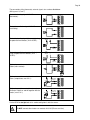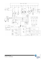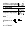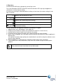
1
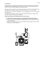
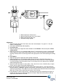
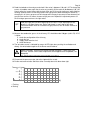
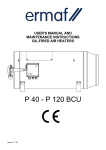
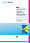
USER MANUAL AND INSTALLATION INSTRUCTIONS RGA 100 NATURAL GAS PROPANE Version V11, 04-03-2009 Pag 2 Congratulations on your purchase! We're sure you'll be very happy with your new ERMAF RGA100 EC Declaration of Conformity We declare that the design and model of the machine described above being placed on the market by ourselves complies with the relevant health and safety requirements of the EC Directive. Note In order to ensure that your new equipment will always work properly and efficiently and to ensure your personal safety, we would ask you the following: Please read through this User Manual thoroughly and take particular note of the warning and safety instructions before starting up the machine for the first time Index 1. General Information ............................................................... 5 1.1. Symbols........................................................................... 5 1.2. Special safety instructions ............................................... 5 1.3. General safety instructions .............................................. 5 1.4. Electrical equipment ........................................................ 6 1.5. Maintenance .................................................................... 6 1.6. Ordering spare parts........................................................ 6 1.7. Liability ............................................................................ 6 1.8. Power Interruptions ......................................................... 6 1.9. First aid............................................................................ 7 1.10. Waste ............................................................................ 7 2. Technical data ........................................................................ 8 System information ................................................................. 8 3. Installation ............................................................................. 9 3.1 Placement........................................................................ 9 3.2 Connecting ...................................................................... 9 3.3 Electricity ......................................................................... 9 3.4 Gas ............................................................................... 11 3.5 Operation....................................................................... 12 3.6 Adjustment..................................................................... 13 4. Maintenance ........................................................................ 14 5. Errors ............................................................................... 14 Annex: A Burner pressure .................................................................... 15 B Error list ............................................................................... 16 C Spare parts list...................................................................... 17 D Accessories .......................................................................... 19 Manual RGA 100 Version V11, 04-03-2009 Pag 4 1. General Information 1.1. Symbols You will see the following symbols when you read through the User Manual: Warning of a general danger Warning of dangerous voltage Wear protective gloves 1.2. Special safety instructions CAUTION This indicates risks or unsafe processes, which can easily cause slight injury or damage to property. NOTE This provides information on how to handle the equipment effectively, economically and in an environmentally sound manner. 1.3. General safety regulations This appliance is for use in animal sheds and greenhouses. Use of the equipment for any other purpose shall be regarded as improper use. The manufacturer will not be liable for any damage resulting from improper use; the user shall bear the sole risk thereof. Proper use of the equipment also entails observing the manufacturer's conditions of operation, maintenance and installation. Currently applicable accident prevention regulations and all other generally recognized rules of occupational medicine and safety must be observed. Check all safety and operational equipment • before starting up • at reasonable intervals • after any modifications or maintenance work to ensure that it is safe and fully operational. With storing manure, gases are formed which are partly dissolved. These poisonous and explosive gases (e.g. sulphurhydrogen and methane) can be released during stirring and rinsing. With a source of ignition a big explosion may occur. To prevent a hazardous situation shut off the appliances completely before stirring or rinsing. Also observe the following points: • Close the doors when manure is stored outside. • Ventilate the room thoroughly. Notice: No account is taken with general hazard of fire in this manual. Consult your fire insurance company and/ or your local fire brigade for more information. 1.4. Electrical equipment Only a specialist must perform any work extending beyond the scope of equipment maintenance. Always disconnect the appliance from the mains before performing any work on it. Before starting up the appliance, examine all electrical wiring for any visible defects. Change any damaged wiring before switching on the appliance. Have any plug devices that are damaged or destroyed replaced by a qualified electrician. Do not pull the plug out of the socket by the flex. Covering electric motors can cause high temperatures to build up, which can destroy the electrical equipment and cause fires. 1.5. Maintenance Always disconnect the appliance from the mains before working on the electrical equipment! Only persons who have the training, knowledge or practical experience to ensure that the repair is done properly should carry out repairs. Maintenance, repair and cleaning work should only be carried out with the drive switched off and the motor idle. The same applies to the rectification of functional defects. Wear protective gloves if there is a danger of injuring your hands! The user must satisfy himself that the appliance or machine has been returned to its proper state after carrying out repair work. Technical equipment must not be re-started until all safety devices are in place. Spare parts must as a very minimum correspond to the technical requirements specified by the manufacturer of the equipment. This will be the case if, for example, original spares are used. 1.6. Ordering spare parts When ordering spare parts, always indicate the following: • Code no. and description of part or item number with description and manual number for uncoded parts; • Number of original invoice; • Electricity supply, e.g. 230/400 V, 3 ph, 50 Hz. 1.7. Liability Any unlawful alterations to the machine or the software will rule out manufacturer liability for any resultant damage. Manual RGA 100 Version 11, 04-03-2009 Pag 6 1.8. Interruptions We recommend installing warning systems to monitor your operating equipment. This will protect your animals and consequently your economic existence. In case of a power failure, the emergency power unit should automatically switch on. Power units with cardan transmission for attachment to tractors are also suitable for use as emergency power units. Please consult your property insurance company for more information. 1.9. First Aid Unless explicitly specified otherwise, there should always be a first aid box at the workplace in case of accidents. Any material removed from the first aid box must be replaced immediately. If you ask for help, always provide the following information: • where the accident happened; • what happened; • how many persons injured; • what the risk of injury is; • who is reporting the accident! 1.10. Discharge After the installation or repairs of the installation, the packaging and non-usable waste should be delivered to the appropriate places. The contents of this manual are liable to change without notice. If you discover any errors or inaccurate information, we would be grateful if you could inform us of these. All trademarks named or depicted in the text are trademarks of their respective holders and are recognized as protected. Copyright 2004 by Ermaf In the event of queries, please contact: Elster-Instromet B.V. Industrieweg-Zuid 32 NL-3958 VX Amerongen Telefon : +31 343-47 37 20 Fax : +31 343-47 37 30 Internet : www.ermaf.nl E-mail : [email protected] 2. Technical Data Output Gas connection Burner pressure Maximum line pressure Gas consumption : : : : : Power supply Current : : Air circulation : Throw : Materials : Length Width Height Weight : : : : ..............................................................................±60-95 kW .........................................................................................3/4" ........................................................................... see annex A 100 mbar Natural gas L:......................................................... ± 9,5 m³/h Natural gas H: ...........................................................± 8 m³/h Propane: ................................................................ ± 6,9 kg/h ................................................................ 230 V/50 Hz/900 W IA / IN ................................................................. ± 22 A / 5,3 A Heating............................................................... ± 5.000 m³/h Ventilating .......................................................... ± 7.000 m³/h .................................................................................... ± 40 m Mantle ...................................................... Stainless steel 430 Burner chamber ....................................... Stainless steel 430 BCU ................................................................................PPE (Ambient temperature BCU: -10 to +60°C) The materials used are capable of withstanding the maximum loads. ................................................................................... 196 cm (Diameter Mantel / Total)....................................... 61 / 87 cm .................................................................................... 73 cm .................................................................................. ±110 kg System: The combination of ventilator for air, gas regulator for gas and a short ignition ensures a good combustion. Safety devices are built in to prevent dangerous situations and to prevent damage to the appliance: 1. Two pressure switches check for sufficient airflow 2. Gas- air-mixture stabilized by regulator 3. The burner is being checked by means of ionization 4. Two class-A gas valves for a certain shut down of gas flow 5. Overheat sensors for appliance and ventilator The burner control unit (BCU) checks and controls all connected components. Functioning and errors are signalized. Manual RGA 100 Version 11, 04-03-2009 Pag 8 3. Installation 3.1 Placement The number of appliances required depends on the size and nature of the room, the required temperature and the relevant climate zone. The appliance must not be connected to or inside closed duct/pipe systems. Suspension/placement Place the appliance so that: • the inlet of the appliance is at least 1 meter away from the wall • it’s not pointed to flammable materials and at least 3 meters away from a wall. • the delivered heat cannot cause any damage (also concerning e.g. dehydration) • neither at the inlet- nor the outlet obstacles can influence the free airflow. • it hangs horizontally 3.2 Connecting Work on the heater; • Installing • Commissioning • Adjusting • Converting for other gases and connecting to the local electro- and gas supply should only be done by a qualified installer with approved connection materials. Local regulations must be observed for connecting to the electricity and gas supplies Before installation, check that the local distribution conditions, nature of gas and pressure, and the current state of adjustment of the appliance are compatible (see data plate) Also mind the ambient temperature; thaw in the BCU is not allowed The heater needs a constant power supply for cooling down, do not use the power supply as a thermostat. 3.3 Electricity Unscrew the lid from the BCU and pull it off with both hands. Inside, you will find the wiring diagram: Thermostat Heating Thermostat ventilating External reset For connection of the mains 230VAC, use the contacts 1(2) and 3(4) (Not phase sensitive) Do NOT connect the heaters to 400VAC Manual RGA 100 Version 11, 04-03-2009 Pag 10 The connection of the thermostat, external signals etc. are described below: (Wiring max. 2,5 mm2.) T 230VAC V 230VAC +24V AC/DC 0 +24V AC/DC 24 25 26 27 28 +24V AC/DC 24 25 26 27 Contact for heating signal (thermostat) using the potential free contacts (24 V AC/DC): T Contact for ventilation signal (ventilating) using the potential free contacts (24 V AC/DC): +24V AC/DC 0 V R 230VAC N L1 253VAC max 2A 20 21 22 23 253VAC max 5A 22 23 24 25 A Optional connection contact for external ventilator. Switch on and off together with the heater ( max 5 A ! ): N EV 30 31 32 Optional connection contact for external reset button (make contact): Optional connection contact for external alarm ( lamp/claxon, max 2 A ! ): 27 28 29 30 31 Contact for ventilation signal 230VAC (ventilating): 28 29 30 31 Contact for heating signal 230VAC (thermostat): L1 Put the BCU lid straight back to its socket and tighten it with the screws. Do NOT connect other heaters on contacts 28 till 32 (Phase sensitive) Manual RGA 100 Version 11, 04-03-2009 Pag 12 Starting delay When multiple appliances start at the same time, some appliances may not get enough tension (230V) or gas(pressure) The BCU (lid) has a potentiometer (tE) with which per appliance a start delay of 0-60 seconds can be set. Per appliance a delay of 5-10 seconds should suffice. The following settings are set by the producer and should NOT be altered. Changes might lead to damage! Cooling down period: A standard of 10 seconds cooling down period is set but a longer period can be set. The middle potentiometer can add 0 to 100 seconds Minimal burning time Every time a appliance starts, there is a short incomplete combustion A minimal burning time can be set with the left potentiometer, with which also life expectancy of relays, engine and other parts can be extended. (Only necessary when room thermostat is set too sensitive) Range: 0-180 Seconds Put the BCU lid straight back to its socket and tighten it with the screws. Modulating For modulating the heater between 60-100kW, use the separate 2-pole terminal block in the BCU socket. It leads to the ZVP (Volt->PWM converter). Regulate the voltage between 5 - 10VDC. Also connect the transparent AMP connector (MT Edge) on the circuit board of the burner ventilator. Standard, the plug is loose, without 5-10V power supply the ventilator will not turn or turn slowly. 3.4 Gas Connection: ¾” at the gas combination. Use for suspension with chains an approved flexible gas hose. Always use approved tightening material. 3.5 Operating Disconnect from 230V mains and open the (manual) gas valve. Press the white button (ON/OFF) of the BCU until one of the other LED’s light up, the appliance is switched “on“ in the last chosen setting. By continuously pushing the red button different settings can be chosen (the chosen setting will start after 3 seconds) OFF Appliance will not react to any signal AUTO Appliance waits for a signal from the thermostat for heating or ventilating Appliance will start burning (manual setting) The ventilator will start running (and only this) + AUTO Appliance will ventilate continuously and waits for a signal from the thermostat for heating. In every setting where the appliance should burn the following will happen: 1. Appliance waits until “starting delay” is over (0-60 sec) 2. Checking of “off” position air switches (the ventilator will switch off, in case it was on) 3. Ventilator will turn and will switch the air switch to “on” position 4. 5 seconds later the ignition transformer starts sparking and the gas valves will open. 5. When a flame is detected (via an ionization current) the ignition transformer will stop, the appliance is burning safely. (The ignition transformer stops igniting one second before the end of the safety time whether or not a flame has been detected) 6. When the appliance is switched off, the ventilator will continue for at least 10 seconds. 7. The STW/STB (max. safety temperature) might switch the ventilator on again for cooling down purposes. Always allow the heater to cool down at least 100 seconds. Manual RGA 100 Version 11, 04-03-2009 Pag 14 3.6 Adjustment Although the heaters are adjusted by the producer for a correct air/gas mixture, they must always be checked again and re-adjusted at first use. The chimney-, fresh air system but also variation in gas mixtures can result in incorrect working of the heater and overload. When the gas mixture and pressure was mentioned by ordering, the heaters are already adjusted and will probably start immediately or may be after a few times when there is air in the gas system When flue gases are measured, the Lambda (excess air) should be between 1,25 and 1,35 for a good nett return (>91%), This means O2 values between 4 and 5,5% (Lower is possible when good, clean air supply can be guaranteed and when not too much CO is produced) Preparing for Adjustment the RGA100 gasheater (using the figures) a) Check the chimney whether the chimney is assembled according to the technical guide. b) Connect the fresh air hose between the plastic control cabinet and the chimney connection. c) Drill a hole in the chimney according to the drawing to place the measurement tool or analyser into the chimney tube. d) Open the pressure nipple (3) (loosen the crew inside) and connect the pressure meter. (Do not forget to fix it again after adjustment) 1. 2. 3. 4. Measure point gas inlet pressure Adjustment burner pressure (via air factor) Measure point burner pressure Correction setting high/low Adjustment: 1. Start the heater and check if the heater starts after some attempts. If so, go to 11, if not, the heater is deranged and: 2. The heater should be adjusted completely 3. For natural gas: 4. Adjust the gas pressure (2) till the white indicator on the indicates 1 with the help of a 2.5 mm socket wrench 5. Adjust the air valve (nr.12 in drawing chapter Annex C) so that the wing screw is in position 45°°. How to adjust the screw: loosen with the help of a tool of 13 mm the locking nut while blocking the wing screw by hand. Put the wing screw in the right position of 45° while fastening the locking nut. 6. For Propane: 7. Adjust the gas pressure (2) till the white indicator indicates 2 8. Adjust the air valve (nr.12 in drawing chapter Annex C manual) so that the wing screw is in position 25°°-30°°. How to adjust the screw: loosen with the help of the tool of 13 mm the locking nut while blocking the wing screw by hand. Put the wing screw in the right position of 25°-30° while fastening the mutter. 9. Start the heater and check if it starts to burn. If not close the air valve a little bit and try it again. Do this exercise again till the heater keeps burning. 10. When the heater burns check the level of CO by means of the analyser . If CO level increases too much too fast (>2000 ppm) stop the measurement, disconnect the analyser from the chimney and refresh the analyser. Then open the air valve a little bit more and do the measurement again. When the CO does not increase too much leave it in the chimney. 11. The heater burns now for some minutes , check the burner pressure according to the figures in chapter 8 of the manual and the type plate on the heater. Adjust the burner pressure with the help of the socket wrench of 2,5 mm. Manual RGA 100 Version 11, 04-03-2009 Pag 16 12. Read the lambda on the analyser and check if the value is between 1,20 and 1,35. To change the excess air lambda, move again the air valve very carefully till the value will be between 1,20-1,35. How to adjust the screw: loosen with the help of the tool of 13 mm the locking nut while blocking the wing screw by hand. Put the wing screw in the right position while fastening the mutter. By changing this air valve, gas pressure will change too in the way that more air means decrease of gas pressure and less air means increase of gas pressure. Repeat this adjustment process till the air and gas pressure have the right values. Look at the gas pressure while adjusting the air valve. A small adjustment results directly in a change of pressure. Do the adjustment in small steps of 0,5 mbar. Please remember: more air is decrease of gas pressure, less air means increase of gas pressure. 13. Measure the combustion gasses in the chimney. CO should be under 100 ppm (at 0% O2). If CO is higher: a. check the configuration of the chimney, b. check the fuel c. supply some more fresh air d. check the burner 14. The ionisation current is indicated by means of LED lights when pushing the red button and directly the white button together on the Burner control cabinet. Before installation, check that the local distribution conditions, nature of gas and pressure, and the current state of adjustment of the appliance are compatible (see data plate) Also mind the ambient temperature; thaw in the BCU is not allowed 15. Disconnect the pressure meter (close the nipple with the screw) 16. Do the measurement after 30minutes to be sure adjustment has been done right. There are 11 steps: ○ 0 ○ Flashing ● Burning ○ 2 ● 4 ○ ● 6 ● ● 8 ● ○ ● ● ● ○ ● ● ● ● ● ● ● ● ● ● ● ● ● ● ● ● ● 10 12 14 16 18 20 [µA] 4. Maintenance Do not use water to clean the appliance! Inadequate cleaning can result in damage by fire. Have your appliances checked and adjusted by a recognized gas fitter at least once a year. The appliance must be thoroughly cleaned of dust at regular intervals and after every throughput. Do not use water. Clean with a compressor. Clean the appliance with compressed air before every use. Disconnect from main power! Method: • Blow through the appliance on the inside. Especially remove dust accumulating around pressure measuring points. • If using propane, make sure the exhaust opening on the gas pressure governor is clean. 5. Malfunctions A malfunction is shown by the big red LED on the BCU. The internal malfunction contact (21,22) closes. The kind of malfunction is shown by the blinking red LED’s (No. 1-5). See annex B. To reset the appliance the red button should be pushed for at least half a second. Manual RGA 100 Version 11, 04-03-2009 Pag 18 Annex A: Burner pressure settings The burner pressure depends on the output, the Wobbe-index and diameter of the injector. The Wobbe-index is a relation between calorific value of the gas (Hs) and the square root of the relative density of the gas (d). Hs Wobbe-index= √d The burner pressures are valid for 15°C atmospheric 1,013 mbar pressure and dry Gas The inlet gas pressure can decrease because of resistance, the needed gas pressure might not be reached. Always check the inlet pressure of each heater during operation. 1. Natural gas: Inlet pressure: .............................................................. 20 - 25 mbar RGA 100 Injector 12 x ø3,0 mm Wobbe index [ kWh/m3] (MJ/m3) ] 11,7 (42,2) 11,9 12,15 L-gas 12,40 kWh/m3 12,65 12,90 13,25 13,50 13,75 14,00 14,25 14,50 14,85 H-gas 15,00 kWh/m3 15,25 15,50 2. Propane Inlet pressure Injector Burner pressure Burner pressure [mbar] 15,1 14,4 13,9 13,3 12,8 12,3 11,6 11,2 10,8 10,4 10,1 9,7 9,4 9,1 8,8 8,5 :............................................................. 50 mbar : ............................................................ 12 x ø 1,80 mm : ............................................................ 23 mbar These values are for 100% propane only. For propane/butane- mixes other pressures should be set. These pressures should be requested at the producer. Using propane/butane mixes without adjusting the burner pressure can lead to a bad combustion or serious damage to the heater. Annex B: List of possible malfunctions LED 1* 2 3 4 Malfunction Contact between 9 and 10 is broken Cause (▄) / Solution (►) ▄ Fuse F2 defect, check for separate thermostat connection Both air switches are switched before ventilators ► Check switches turn. One or both of the air switches ► Check switches for functioning doesn’t switch when ventilator turns ▄ Switch/hoses dirty ► clean ▄ Fuse F1 defect (8 A, slow, H ) BCU did not recognize a flame during ▄ No (adequate) ignition the safety time. ►Check distance electrodes; check connection ignition cable; clean ignition electrode; check ignition This appliance has 3 start attempts. ▄ Bad flame signal caused by wrong setting burner The error will reset automatically after ►Adjust burner (pressure) properly the cooling down period until the 3rd ▄ Bad ionization current caused by dirty or badly connected time. ionization electrode ►clean ionization electrode; check ionization cable and earth connections ▄ Air is the gas supply -> Bleed gas piping ▄ Short circuit at ignition- or gas valve connection BCU ► Check wiring. Advise: When a short circuit is found at the gas valve exit, the BCU should be sent back to the manufacturer, or: 1. Replace fuse F2: 3,15 A (slow, H) and check security function 2. Close manual gas valve. 3. Start the appliance for a few times and check security function 4. When a malfunction is detected, send the BCU to the manufacturer. WARNING! When this security function is not checked, the gas valves may stay open and unburned gas might flow into the room – Danger of explosion! 5 4+5 3+5 2+5 Max. temperature of overheat cut off device (STB) exceeded. (manual reset needed) Max. temperature of overheat guard device (STW) exceeded. (automatic reset) In three start attempts, during the safety time, the connection 9+10 has opened (gas inlet pressure switch?) (Oscillates) Premature flame signal (before a flame is possible) Incorrect function of overheat cut off/guard device ▄ Ventilator does not cool down ▄ Dirt ► Clean ► Set a longer cooling down period ▄ Dirt ► Clean ► Ensure a stabile inlet gas pressure; ► Higher inlet pressure ► Use larger gas pipes ► Faulty flame signal. ► check connections ▄ Temperature sensor is below –20°C 3+4 Time between two starts is too short. (automatic reset after waiting time) Flame dropped during operation ▄ Bad flame signal caused by wrong setting burner (Heaters with 3 start attempts will make a ► Adjust burner (pressure) properly new start when the heater has burnt for at ▄ Bad flame signal caused by dirty or badly connected 2+4 least 2 seconds) ionization electrode. ►Clean ionization electrode; check Ionization cable and connection to earth Remote reset (connection 31/32) is switched ► Only push reset when appliance has a 1+4 longer than 10 seconds. (Permanent reset) malfunction Flame signal did not dissipate within 5 seconds ► close gas supply 1+3 after the gas valves closed -> Gas valves do not ► check correct functioning burner / gas close properly. valves 1+2 Internal tension error During a malfunction more than 5 times in 15 minutes the remote reset (connection 31/32) is 3+4+5 switched. (automatic reset after waiting time) Errors indicated with a * will reset automatically after the problem has dissolved, sometimes after a small pause. Pushing the reset-button in this case has no use. 1+5 Manual RGA 100 Version 11, 04-03-2009 Pag 20 Annex C: Parts list No. 1 2 5 6 7 8 9 10 11 12 13 14 15 16 17 18 Name Motor ElnorBX275 ...................................................................................................... Grille RGA100 ............................................................................................................ Fan 400mm white, 8-blade ......................................................................................... Air inlet duct RGA100 ................................................................................................. Air hose inside............................................................................................................ Clamp rings (2x) ......................................................................................................... Burner RGA100 V4 without accessories..................................................................... Mantle short................................................................................................................ Burner chamber RGA100 complete............................................................................ Mantle long................................................................................................................. Air supply limiting valve .............................................................................................. Injector: Natural gas (12xø3,0mm) .......................................................................... Propane (12xø1,8mm)............................................................................... Baffle disc (ø 48mm) .................................................................................................. Gas hose stainless steel flexible................................................................................. Ionization electrode .................................................................................................... Ignition electrode ....................................................................................................... TSK1054 Temperatursensor 6x45 1M T.B.V. RGA..................................................... Centrifugal ventilator (option) 20 Nicotra DDC 321-321 (230V)............. Nicotra DDC 321-321 (400V)............. 21 Grille flat EB 35 ................................. 22 Lid rear complete RGA 95 ................. 23 Service hatch 24 Lengthening tube 30cm N51900051 N51900053 N52700006 N52100005 Code N50820001 N50820031 N50820029 N50820033 N50820048 N50820049 N50820018 N50820015 N50820070 N50820013 N50820025 N50820021 N50400066 N50260167 N50820047 N50820082 N50260030 N50820039 No. 1 1A 2 3 4 5 6 7 8 9 10 11 12 13 14 15 16 17 18 Name Code Ziehl Abegg V->PWM Signal converter ................................................................ N50820027 Setting jumper: Closed : 0->10V = 0->100% Open : 0->10V = 100->0% (Motor-) Relay Omron LY2 / Finder 56.32 ................................................................ N50260024 Socket PTF08A-E for Relais LY2 ...................................................................................... N51600011 Air pressure switch Kromschröder DL-5E-1................................................................ N50280102 Support air pressure switch ............................................................................................... N50820009 Gas combination Kromschröder CG20V................................................................ N50280116 Support gas combination................................................................................................ N50820012 Angle 1/8” no. 92................................................................................................N50310024 Support capacitor motor ................................................................................................ N50820011 Motor capacitor 16µF, 400V .............................................................................................. N52800034 N50820070 MVL RG148 burner ventilator complete................................................................ Flange air inlet................................................................................................................... N50820025 Flange air outlet with valve ................................................................................................ N50820026 BCU-300 RGA gas lid ...................................................................................... N50260444 BCU Socket (Including ignition transformer)..................................................... N50260102 Ignition transformer Eichhoff 4718/54 .............................................................. N50260109 Ignition transformer Danfoss EBI-1P ................................................................ N52600028 Plug RGA main ventilator ................................................................................................ N50820045 Counter plug ventilator ................................................................................................ N50820046 Gas tube ¾ “ 177mm with gas pressure measuring point.................................................. N50280137 Gas tube ¾ “ 95mm................................................................................................ N50280136 Manual RGA 100 Version 11, 04-03-2009 Pag 22 Annex D: Accessories - Chimney set.................................................................................................... N50820003 Room thermostat 230V .................................................................................. N50260146 Natural gas Connection set natural gas 1“ 1,5 meter ........................................................ N52600070 Propane Connection set propane ½“ 1,5 meter............................................................ N52800136 - Certified propane hose with valve, 2 meter ..................................................... N52990209 - Propane regulator RECA 1,5 bar -> 50mbar ................................................... Certified propane regulator: GOK (12kg) 0,5-2,5 bar -> 50 mbar .................... Mind the output of the heater! Gas valve ½“ in/out......................................................................................... Gas valve ½“ in/in........................................................................................... - N52600023 Propandruckregler N52600039 RECA 1,4 ba N52600027 N52600019 Annex E: Return of goods form User name Address Telephone number E-mail address Returned by ; Mr./ Mrs Date : : : : : : Description of returned goods Quantity Serial number heater Power supply V/ Inlet gas pressure mbar Working gas pressure mbar Reason for return Description of failure Requested action Remarks Credit / Exchange / Repair Return date ; _________ Please return the goods to your nearest Dealer Manual RGA 100 Version 11, 04-03-2009 Hz