1
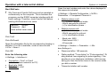
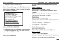
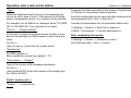
Comfort Soft
Configuration Software
Installation and
Operating Manual
Please observe the safety instructions and
read through this manual carefully before
commissioning the equipment.
Safety information
General information
General information
Safety information
NOTE
Warranty
!
E Any warranty claims against the manufacturer shall
become null and void in the event of installation and
commissioning of the software or hardware in a way
that is not in accordance with the information provided
in this user manual and the documentation referred to
herein.
E The manufacturer shall not be liable for any direct, special, incidental or consequential damage that may arise
as a resulting of using this product. Claims based on
mandatory product liability provisions shall remained
unaffected.
Modifications of the product and operating instructions
We reserve the right to modify the product and the operating instructions at any time and without prior notice.
!
2
Information on changes made at short-notice can be
found in the "Read_me.txt" file on the installation diskettes or the CD-ROM.
!
!
Information on whether your controller is capable of
communication can be found in the pertinent user
manual.
Refer to the user manual supplied with your controller.
The limit values and wiring specifications must be observed.
After the installation of a CoCo PC (supply voltage
ON), the equipment needs about 2 minutes to load the
bus configuration. Error-free operation is only ensured
after this initialization phase.
NOTE
General information
Important text passages
Functions
>> << Sections that are shown in this way represent
commands that are invoked via menu assistance.
•
•
•
•
•
•
•
E This attention symbol indicates dangerous situations.
!
Lines marked in this way provide tips.
[A] Drive letter; in this case the floppy disk drive.
System requirements
The system requirements described in the following only
specify minimum default values.
Hardware
•
•
•
•
•
•
commercially available PC (Win95 capable)
screen resolution min. 800 x 600
3.5" disk drive or CD-ROM drive
keyboard and mouse
modem* or ISDN card*
commercially available telephone cable on telephone
connection*
*) Only applies to control via a telecommunication network
•
!
Reading in the configuration of a heating installation
Access controller on bus
Read-in / modify / transmit parameters to controller
Transmit saved parameter records to controller
Read-in measured values
Read-in error messages
Documentation of temperature curves, for example,
through integrated data recorder (log function)
Automatic fault notification function via the PLC
(only in connection with a "CoCo-PC active")
Telephone charges arise for connections made via a
telecommunications network.
When using a "CoCo-PC active", SMS messages can be
sent to up to three stored telephone numbers [e.g. mobiles] in the case of a fault.
The "CoCo-PC active" also provides the possibility of connecting the controller to a control system via the
specified, integrated "Open"-RS 232 Interface
(only for controllers which support this mode).
Software
•
•
Microsoft Windows PC operating system from Windows 95 or later
Comfort Soft from Version 3.0.0
3
Contents
Contents
General information
2
Safety information
2
Warranty
2
Modifications of the product and operating instructions
2
NOTE
2
Important text passages
3
System requirements
3
Hardware
3
Software
3
Functions
3
Contents
4
Scope of delivery
6
Use
6
Comfort Soft with optical interface
6
Comfort Soft with communications module
CoCo PC as an in-house application
6
Comfort Soft with communications module
CoCo PC and a modem
7
Comfort Soft with communications module
CoCo PC and a telecontrol station
7
Installation of the software
8
NOTE
8
Installation
8
USB interfaces
9
Deinstallation
9
System => Installation
10
4
General information
Use with the optical interface
10
General information
10
Connecting up
10
Use together with "CoCo-PC active"
11
Resetting the CoCo-PC / Loading default values 12
Function selection for "CoCo-PC active"
13
PC connected directly to bus
14
General information
14
Establishing a connection
14
Remote control via modem with message function
16
General information
16
Programming the "CoCo-PC active" (modem
operation)
17
Establishing a connection
17
Entering parameters
18
Selection mode
18
Init-String functions
19
Modem tool => Modem AT commands
19
GSM Modem
20
SMS function
21
SMS target units
22
SMS operation
25
Fault input / output
26
After completing input
28
Status Inputs
28
Installation in the system
29
Operation with a telecontrol station
30
General information
30
Establish connection (in the system)
30
Contents
General information
Working steps for the monitoring station
31
Operation
35
Start Comfort Soft - establish connection
35
Use with the optical interface
35
Use directly on the CoCo-PC
35
Remote control via modem with message function
35
Disconnect
37
User interface
38
File menu
38
New
38
Open ....
38
Close
38
Save
38
Save as ....
39
Export
39
C:\....\File name
39
Quit ....
39
View menu
39
Icon bar
39
Status bar
39
Communication menu
40
Make a direct connection
40
Make a modem connection
40
Disconnect
41
Read configuration again
41
Devices menu
41
Indicate
41
Tools menu
42
Protocol
42
Time
Select language
Change code number
CoCo-PC
Protocol menu
>>Protocol -> Settings<<
>>Protocol -> Start<<
>>Protocol -> Stop<<
>>Protocol -> Delete<<
>>Protocol -> Open graph<<
Window menu
? menu
Frequently used functions
Read configuration / controller data
Indicate
Change parameters
Edit parameters
Transmit parameters
Write protocol
Appendix
Troubleshooting
Glossary
USB-to-Serial-Adapter
Modem List
42
42
43
43
43
43
43
43
43
44
44
44
45
45
46
46
47
47
48
49
49
51
51
52
5
Scope of delivery
Scope of delivery
!
Before beginning with the installation, check the package delivered for completeness based on the packing
list.
Use
•
•
•
•
6
Mobile use, e.g. for installation personnel, together
with an optical adapter or a CoCo-PC for on-site service or configuration during installation/modification of
the heating system using a notebook.
In-house use with the CoCo-PC for direct connection
of the PC to the heating system's bus for implementation as a monitoring unit or for programming [security
personnel, proprietor].
Remote configuration/monitoring of a heating system
with the CoCo-PC + modem for communication with
the heating system via a telephone and for automatic
fault notification via SMS [service company, holiday
accommodation].
Remote service with the Wikon telecontrol station.
General information
Comfort Soft
with optical interface
Designation
Comfort Soft on CD
Adapter cable for optical interface
Comfort Soft with
communications module CoCo PC
as an in-house application
Designation
Comfort Soft on CD
CoCo-PC = converter for the RS232 interface of the PC
Connection cable for the RS232 interface of the PC
Plug-in power supply unit 230/12V
(only required in certain cases)
Scope of delivery
General information
Comfort Soft with
communications module CoCo PC and a modem
Designation
Comfort Soft on CD
CoCo-PC active =
converter for the RS232 interface of the PC
Plug-in power supply unit 230/12V
(only required in certain cases)
2 modems *)
Comfort Soft with
communications module CoCo PC and a telecontrol
station
Designation
Comfort Soft on CD
CoCo-PC active =
converter for the RS232 interface of the PC
Plug-in power supply unit 230/12V
(only required in certain cases)
Fewis MP8(PLC) NT
telecontrol station with transparency mode
*) We recommend the use of the modem we have on offer
(function tested) for use in the heating system. We cannot
assume any guarantees for other modems. Any commercially available modem can be used for application with the
PC. A list of modems which have been tested is provided
in the Modems Appendix. If you use another modem which
operates error-free, please notify us so that we can extend
the list.
1 modem *)
7
Installation of the software
Installation of the software
General information
Installation
•
If the computer is switched off, switch it on.
•
Terminate all programs (Explorer can be used to start
the Setup.exe file).
Deactivate any virus protection and screensaver programs for the duration of the installation to prevent
conflicts.
Following installation, Comfort Soft must be started once
with Administrator rights (communication test). Any user
can then use Comfort Soft.
•
For installation from a set of disks:
Insert the installation disk 1 in the disk drive and start
the "Setup.exe" file on the disk.
Prior to the installation of Version 3.0.0 or later, all the versions of Comfort Soft earlier than 3.0.0 must be deinstalled.
•
For installation from the CD:
Insert the installation CD in the CD drive and start the
"Setup.exe" file on the CD.
If a Beta version of V 1.7.0 is/has been installed, certain
entries in the Registry must be deleted manually. To do
this:
•
For installation from the hard disk:
Copy all the files from the installation CD to an installation directory on the hard disk and start the
"Setup.exe" file in this directory.
NOTE
The installation and deinstallation on operating systems
which support protection rights for files (e.g. NT) may only
be performed with Administrator rights. Write permissions
in the system directories are required for the installation.
•
•
•
•
•
•
•
•
•
8
Activate "Execute" in the Start menu
Enter regedit.exe (registration editor)
Open the following directory:
HKEY_LOCAL_MASCHINE
System
CurrentControlSet
Services
VxD
Delete "TDLPT"
!
The installation screen appears. Follow the instructions
on the screen.
The installation can be stopped or interrupted at any time
by clicking on >>Cancel<<.
Installation can be resumed at a later point in time. In this
case, repeat al the previous steps as for a new installation.
Installation of the software
General information
The following screen message appears after successful
installation: "Set-up completed".
Restart the computer.
USB interfaces
If your computer is only equipped with USB interfaces, use
commercially available USB-RS232 adapters to connect
the dongle and optical adapter/CoCo-PC.
Deinstallation
The installation and deinstallation on operating systems
which support protection rights for files (e.g. NT) may only
be performed with Administrator rights. Write permissions
in the system directories are required for the deinstallation.
•
Start the computer as described in the system manual
relevant for the computer.
•
Start Deinstallation under Windows with:
>> Start/Settings/Control Panel<<
•
Double click the "Add or Remove Programs" icon.
•
In the text bar, click on "Comfort Soft" or the program
name assigned by yourself and then click on
"Add/Remove".
•
The screen message "Delete File or Application" appears.
•
Click >>Yes<< in order to confirm Deinstallation.
!
Deinstallation is executed. After successful Deinstallation the following screen message appears: "Deinstallation was successfully completed".
9
Use with the optical interface
System => Installation
System => Installation
Use with the optical interface
General information
Installation/Service personnel
The optical interface enables mobile use of the program at
different locations by using a notebook.
CAN Bus
BM
BM
BM
BM
Z
1
Only one controller with an optical interface is required in
the heating installation.
!
x q
KFS
SPFS
4
2
Refer to the controller's user manual to find out
whether it is equipped with an optical interface.
Connecting up
Insert the Sub-D plug (9-pin) into the 9-pin socket (serial
interface) of the computer.
Insert the optical adapter into optical interface of the controller.
Start "ComfortSoft.exe" in the installation directory.
3
Open the menu: >>Communication<< and select >>Make
a direct connection<<.
Explanation of diagram
1
2
3
4
10
Heating programmer
Optical adapter with interface cable to RS232 of the
PC
Notebook
Heating installation
Enter – when known - the highest heating circuit number in
the heating installation and confirm it, or confirm the predefined program entry, by clicking the "OK" button.
!
If the following message appears: "No serial connection available!"
=> continue by reading the chapter "Fault location".
The further steps are explained in the chapter "Operation".
Use together with "CoCo-PC active"
System => Installation
Use together with "CoCoPC active"
A: Connection for the controller
system's CAN BUS
D
A
E
B: Select the "CoCo-PC active"
function
OFF
ON
C: Connection of an additional
power supply (power adapter)
RS 232
Only when the display or the
bus symbol in an operating unit starts to fade or goes
out, or when the "CoCo-PC active" LED no longer
lights up.
F
D: LED, operating indicator
a) LED lights continuously => normal operation
b) LED does not light up => unit not working correctly
1. Check CAN BUS connection: VCC (+,-) >
8V
2. Connect power adapter (C)
c) LED flashes=> CAN BUS is not active
1. Wait at least 2 min. after Power ON
2. Check CAN BUS connection:
Voltage level at H and L ~ 2V DC
VCC >= 8 V DC
~ 2 V DC
B
C
E: More inputs/outputs (see chapter "Functions"):
Signal/Count input 1 => Pin 1 and PIN 4 (ground)
Signal/Count input 2 => Pin 2 and PIN 4 (ground)
Signal/Count input 3 => Pin 3 and PIN 4 (ground)
Signal/Fault output => Pin 3 and PIN 4 (ground)
(Conversion function Pin 3 via Comfort Soft)
RS 485 -> A
=> Pin 1
RS 485 -> B
=> Pin 2
(Conversion functions Pin 1 and 2 via switch (B))
F: RS 232 Connector for direct connection of a computer
(zero modem cable) or a standard modem (RS 232
cable of the modem)
!
The CoCo-PC is configured by means of Comfort Soft
(refer to chapter "Programming CoCo-PC active").
11
Use together with "CoCo-PC active"
System => Installation
Resetting the CoCo-PC / Loading default values
DIN rail
EN 50022 (35mm)
!
G
!
G: Using the spring supplied, the CoCo-PC can be
mounted on top hat rails
•
•
•
•
•
!
12
Altering the function switch "1" while power is being
supplied (power adapter or bus => LED lit up/flashing)
causes the values on the "CoCo-PC active" to be reset
to the factory settings.
Connect CoCo-PC to power supply => LED flashes
Change setting of function switch "1"
LED lights up for approx. 4 sec. and then starts to flash
Disconnect CoCo-PC from power supply => switch off
Set function switch "1" to operation setting
In order to retain the current values defined for the
CoCo-PC active, set the function switch before connecting "CoCo-PC active" to a power supply (bus or
power adapter).
System => Installation
Function selection for "CoCo-PC active"
The function switch (DIP switch) on the front of the "CoCoPC active" is used to set the type of use.
"CoCo-PC active" functions
OFF, OFF
=> ↑↑ (Adr. 1)
for temporarily direct connection to the bus. This address
must not be chosen if the controller's optical interface is in
use. [service-engineer, installation technician]
ON, ON
=> ↓ ↓ (Adr. 2)
for remote control via a modem [e.g. for holiday accommodation or monitoring by a service company]
ON, OFF
=> ↓ ↑ (Adr. 3)
for direct connection of a PC to the bus [in-house use –
stationary; e.g. proprietor, security personnel]
Use together with "CoCo-PC active"
E Several CoCo-PCs can be operated on the bus at the
same time (not applicable for all controllers, please ask
your supplier). An example here is the use of one
CoCo-PC for connection to the security personnel PC
and another CoCo-PC to send SMS notifications via
modem to your mobile phone. At the same time, a
technician inspecting the system can connect his computer via a third CoCo-PC to the bus and, for example,
display some temperature values online with the integrated line printer. The CoCo-PC generates its various
bus IDs for the data traffic on the bus from the function
switch setting. If there are two CoCo-PC with equal
function switch setting on the BUS. You have to
change the Address in one of them via Comfort Soft
(page 20 )
OFF, ON
=> ↑↓ (Adr. 4)
for remote control via the integrated RS 485 [e.g. using a
Wikon telecontrol station, Fewis MP8, with transparent
channel]
13
PC connected directly to bus
System => Installation
General information
PC connected directly to bus
Security personnel, proprietor, service company (mobile
CAN Bus
BM
BM
BM
BM
1
KFS
SPFS
E-Nr 99-678-283
CAN
4
3
2
1
1
2
3
4
RS232
RS485
4
3
use)
Explanation of diagram
1
2
3
4
5
Its use by an installation technician, for example, for mobile
application with a notebook at different locations continues
to be possible.
Establishing a connection
Made in Ge rmany
CoCo PC
2
Gn d
24V DC
1 59 8
24V DC
5
Setting up the system with a direct connection between the
PC and controller via the bus enables it to be used, for example, by a proprietor, in his office or security personnel of
an industrial estate, in a control room, as a fixed monitoring/input station.
Heating installation controller's CAN BUS
"CoCo-PC active" communication module
Connecting cable between serial interface of PC
[RS232] and the "CoCo-PC active" communications
module (zero modem cable)
Computer
DIP switch for "CoCo-PC active" function selection
Connect the CAN bus cable with the "CoCo PC active".
Pay attention to the designation of the connections at this
point.
E IMPORTANT! Bus lines must be spatially separated
from mains cables when installed.
Connect the PC to the "CoCo-PC active" (RS 232 zero
modem cable).
Now switch on the voltage supply for the controllers. =>
LED on the CoCo-PC flashes.
Set the CoCo-PC function switch:
a) For fixed installation: ON, OFF
b) For temporarily use: OFF, OFF
!
14
=> ↓ ↑
=> ↑ ↑
Altering the function switch setting while power is being
supplied (LED lit up/flashing) causes the values on the
System => Installation
PC connected directly to bus
"CoCo-PC active" to be reset to the factory settings. In
order to retain the current values defined for the CoCoPC active, set the function switch before connecting
"CoCo-PC active" to a power supply.
Wait until the Function LED is constant (> 2min).
If necessary, connect a power supply unit (12 V DC) to the
"CoCo PC active". Only if the display or the bus symbol in
an operating module becomes weaker or the LED of the
CoCo PC no longer lights up.
Start Comfort Soft on the PC, open the >>Communication<< menu and select the function >>Make a direct connection<<.
Enter – when known - the highest heating circuit number in
the heating installation and confirm it, or confirm the predefined program entry, by clicking the "OK" button.
The further steps are explained in the chapter "Operation".
15
Remote control via modem with message function
Remote control via modem with message
function
3
4
Proprietor, holiday accommodation, service company,
manufacturer
5
6
7
BM
CAN Bus
BM
BM
BM
Using a PC, 2 modems and the CoCo PC communications module, the heating installation can be
configured from a remote station via the telephone
network. This application is particularly suited to
holiday accommodation owners, service companies and system operators.
KFS
SPFS
Made in Ge rmany
E-Nr 99-678-283
CAN
4
3
2
CoCo PC
1
4
1
2
3
RS232
RS485
Gn d
24V D C
1598
24V D C
6
3
Modem
5
4
Modem
Explanation of diagram
1
2
16
Heating installation controller's CAN BUS
"CoCo-PC active" communication module
Modem in the heating installation (see modem list)
Modem in the monitoring station on the PC (also as
plug-in card)
Telephone line or GSM path (with GSM modem)
DIP switch for function selection
Computer in the monitoring station
General information
1
2
System => Installation
7
!
Where possible, only use the recommended
modems (refer to the Appendix and Read_me.txt
file in the installation data media). No guarantee
may be provided for proper functioning if other modems are used.
System => Installation
Remote control via modem with message function
Programming the "CoCo-PC active"
(modem operation)
When used with a modem, it may be necessary to change
the configuration (modify set values on the "CoCo-PC active").
The "CoCo-PC active" can be programmed
a) prior to installation by means of a direct connection to
the PC, b) during installation by means of a direct connection to the PC or c) after installation by connecting a modem to the remote PC.
!
The modem in the heating installation is initialized by
the "CoCo-PC active". The initialization string is stored
in the CoCo-PC and is sent to the attached modem
when the CoCo-PC is put into service. If the modem
used in the system requires an initialization string other
than the default setting:
[AT &F E0 &D0 S0=1 &W0]
it must be programmed beforehand via a direct connection to the PC, otherwise it is not possible to establish a telephone connection via the modem.
Establishing a connection
Programming without controller:
If the "CoCo-PC active" does not receive its power supply
via the controller bus (e.g. bus is not connected), the
"CoCo-PC active" must be supplied with power via a mains
adapter [12V DC] during programming.
Now switch on the voltage supply for the CoCo. => LED
on the CoCo-PC flashes.
Programming on the controller:
Connect the CAN bus cable with the "CoCo PC". Pay attention to the designation of the connections at this point.
E IMPORTANT! Bus lines must be spatially separated
from mains cables when installed.
Now switch on the voltage supply for the controllers. =>
LED on the CoCo-PC flashes.
Wait until the Function LED is constant (> 2min).
If necessary, connect a power supply unit (12 V DC) to the
"CoCo PC active". Only if the display or the bus symbol in
an operating module becomes weaker or the LED of the
CoCo PC no longer lights up.
Set the "CoCo-PC active" function switch to ON, OFF
=> ↓ ↑.
Connect the PC to the "CoCo-PC active" (RS 232 zero
modem cable).
17
Remote control via modem with message function
Entering parameters
Start Comfort Soft on the PC, open the >>Communication<< menu and select the function >>Make a direct connection<<.
Enter the highest heating circuit number in the heating installation, if known, and confirm it, or confirm the predefined program entry, by clicking the "OK" button.
Select the >>Tools<< menu, open the
>>CoCo PC<< window and enter the
necessary values in the input window depicted
below.
Selection mode
This page compiles the data necessary for establishing the connection to the heating
installation via telephone.
Init-String
The modem in the heating installation is initialized by the "CoCo-PC active". The initialization string is stored in the CoCo-PC and is
sent to the attached modem when the CoCoPC is put into service. If the modem used in
18
System => Installation
the system requires an initialization string other than the
default setting, the string must be programmed beforehand
via a direct connection to the PC because it is not possible
to establish a telephone connection via the modem without
entering the correct Init-String.
System => Installation
Remote control via modem with message function
Default setting: [AT &F E0 &D0 S0=1 &W0]
•
Fix speed at 2400 Baud => &N3
(only when the function is not possible without this extension => Pay attention to setting during selection
with Comfort Soft)
•
Modem commands will not be transferred to the end
unit => E0
Procedure:
a) Check the function using the default Init-String
b) Initialization strings for the modems recommended are
provided in the Appendix and in the Read_me.txt file.
Check whether the modem used is assigned a special InitString and, if so, enter it.
c) If a) and b) prove unsuccessful, refer to the documentation supplied with the modem to find the valid Init-String
and enter it.
Init-String functions
The following options should be entered in "CoCo-PC active" for initialization of the modem in the heating installation.
•
Command prefix => AT
•
Load default values => &F
•
Loudspeaker OFF => M0
•
Ignore any RTS control lines => \Q0
•
Ignore any DTR control lines => &D0
•
Pick up at first dial tone => S0=1
•
Save setting permanently => &W0
The AT commands specified are used by several modems
– please check them using the manual supplied with the
modem.
!
Further information on Init-Strings for modems is available in Internet under: >>www.modemhelp.org<<.
Modem tool => Modem AT commands
The WinZip file ModemTool is located on the installation
disks or the installation CD. Use this file to find out the AT
commands that are valid for your modem.
Install the modem on your PC (see the installation disks or
the installation CD).
In the folder "C:\Programs" on your hard disk create a subdirectory with the name ModemTool.
Extract the files from the WinZip file "ModemTool" into this
folder.
19
Remote control via modem with message function
System => Installation
Run the file
>>ModemTool.exe<< by double-clicking on the symbol.
cess to the data. This effectively protects system data from
being read or modified by unauthorized personnel.
Select your modem in the upper window of the Tool.
[Default= 12345678]
Search for the desired options on the index cards of the
Tool (e.g. error correction ON) and make a note of the AT
commands.
Entering the eight-digit code number after when selecting
the system enables access to the entire system data.
!
CAUTION! The windows are often shorter than the
commands. If you position the cursor in the window
then you can scroll the entire command in the visible
area by using the "left" and "right" cursor keys.
GSM Modem
At use of a GSM modem the appropriate field must be activated and the pin number of the SIM card must be entered.
The Init string must be extended by the addition of
„+CSNS=4“. The expansion is carried out automatically if
the field „GSM“ will be activated.
New code number
At this point, it is possible to assign an eight-digit code
number for access to the controller system data. This code
number is stored in the CoCo-PC.
When the system is selected later using Comfort Soft
via a modem / telecommunication network, this code number must be entered in Comfort Soft in order to enable ac-
20
Confirmation
Re-enter the new CoCo-PC code number to prevent writing errors.
Bus ID
Several CoCo-PCs can be operated on the bus at the
same time (not applicable for all controllers, please ask
your supplier). An example here is the use of one CoCoPC for connection to the security personnel PC and another CoCo-PC to send SMS notifications via modem to
your mobile phone. At the same time, a technician inspecting the system can connect his computer via a third CoCoPC to the bus and, for example, display some temperature
values online with the integrated line printer. The CoCo-PC
generates its various bus IDs for the data traffic on the bus
from the function switch setting.
Bus ID in CoCo-PC:
-1
1
2
3
=>
=>
=>
=>
Bus ID, automatic according to function switch
[OFF, OFF] Mobile use, technician
[ON,ON] Modem operation
[ON,OFF] Fixed installation PC, security
System => Installation
4
=>
5 to 9 =>
!
Remote control via modem with message function
[OFF,ON] Fewis MP8 Fernwirkstation
free
Older controllers only support the address "0"
Process in CoCo-PC:
1. The CoCo-PC generates its address according to the
above list from the setting of the function switch.
2. The CoCo-PC searches the bus for controllers which
do not support the new addresses. If such controllers
are detected, the CoCo-PC automatically switches to
the address "0".
3. If an address not equal to "-1" is predefined by
Comfort Soft, the CoCo-PC assumes this
address even if it is not supported by all the
controllers.
SMS function
The "CoCo-PC active" in combination with a modem enables the sending of messages (SMS) to various mobile
telephone numbers (maximally three target units) should
certain events occur (bus failure, message or count inputs
1-3). These events and target units can be combined as
required.
If, for example, 2 CoCo-PCs are located on the
bus with their function switch in the same position,
the bus ID of one of these CoCo-PCs can be
permanently changed by entering a bus ID at this
point.
Example: Two monitoring PCs are installed, fixed,
in the heating system. Thus, the function switch of
both CoCo-PCs are in the same position
[ON,OFF]. Therefore, one of the two CoCo-PCs
must be programmed to a free bus address, e.g.
by entering a "3" in the "Bus ID" field, in order to
guarantee the system functions properly.
21
Remote control via modem with message function
SMS target units
This field can be used to enter the target for the SMS message and a text (e.g. the system address or name). This
text is then sent for all events and messages.
Targets
This window contains the
programmed target units.
After clicking on a target already entered, the
>>Change<< and >>Delete<< buttons become
active. Click on the respective button to modify or
delete the selected field.
After clicking on >>New<< or >>Change<<, the
"SMS" window appears in which to enter/modify a
message target. The MS target unit entered is saved
by clicking on >>OK<<. It is then possible to enter
another target unit by clicking on >>New<< again. A
maximum of three target units can be entered.
When entering new targets, please complete the
following fields:
22
System => Installation
Target:
Enter the mobile phone number of the target unit without
extensions (e.g. "0,").
To make it more clear, the mobile phone number can be
assigned a name. This is separated from the call number
by means of a double click.
Example: >>Brown:01713578910<<
Remote control via modem with message function
System => Installation
Provider:
Enter the service number of the provider for the target unit
call number from the aspect of the heating installation or
the CoCo-PC (the number is dialed by the CoCo-PC; refer
to the provider list below).
!
The provider and target unit call number must match.
This means that only the D1 provider sends a message
to a D1 mobile and D2 provider to a D2 mobile.
The following normally applies:
T-Mobile (D1): 0160, 0170, 0171, 0175, 0151
Vodafone (D2): 0162, 0172, 0173, 0174, 0152
E-Plus: 0163, 0177, 0178
O2: 0176, 0179
Example: 01712092522 for a D1 target mobile phone
number (for GSM Modem use you have to dial the international access code in any way)
will be lifted in 2003 (=> ask provider).
If the CoCo-PC or assigned modem installed in a PBX system, a zero and a comma must precede the provider number to obtain an outside line and enter the waiting period,
respectively (comma not for GSM modem).
Example: 0,01712092522 for D1 target mobile phone number.
Protocol:
Select the associated protocol (TAP or UCP) from the provider list and activate it in the input window by clicking on
the white point.
If the <TAP> protocol does not work, select <UCP>, and
vice versa. Further information can be obtained by directly
contacting the provider responsible for the target mobile
phone number.
The fixed assignment of access code numbers to provider
SMS providers for mobile phone networks:
Provider
T-Mobil (D1)
Vodafone (D2)
E Plus
O2 (Viag Interkom)
Log
<TAP>
<UCP>
<TAP>
<TAP>
Access, Modem
0049 (0) 1712092522
0049 (0) 1722278020
0049 (0) 1771167
0049 (0) 1797673425
Access, ISDN
0049 (0) 1712521001
0049 (0) 1722278010
0049 (0) 1771167
-
Access, GSM
00491710760000
00491722270000
00491770610000
00491760000443
For more information please lock for ReadMe.txt in the installation directory or CD
23
Remote control via modem with message function
Faults received:
Select the events which should cause a message to be
sent to the target unit specified. It is possible to select several events for one target call number. It is also possible to
activate an event with various target call number.
For use outside Germany
a) Select a provider in the country where you are using the
mobile phone.
Find a mobile phone provider which makes an analog modem access available for your country. The technical hotline of the provider can state the service number and protocol (TAP, UCP), so that the necessary settings can be
configured in Comfort Soft. Please send the information to
us so that we can extend the list. The service numbers
known to us are listed below (without guarantee). Other
numbers may be specified in the Read_me.txt file.
Austria: (0043)
A1 SMS
Switzerland: (0041)Natel
Belgium: (0032) Proximus
Mobistar
Ireland: (00353) Esat
Norway: (0047)
Telenor
Netherlands: (0031)KPN
UK: (0044)
Cellnet
Vodafone
One-2-One
24
<TAP>
<UCP>
<TAP>
<UCP>
<TAP>
<TAP>
<UCP>
<TAP>
<TAP>
<TAP>
0900664914*)
0794998990
75161621
0495955205
868525352
96890050
0653141414
7860980480
7785499993
7958879889
System => Installation
*) can only be dialed from Austria.
The latest information is available in Internet under
www.intellisoftware.co.uk/products/transports/tap-protocolnumbers.aspx
or
www.gsm4u.cz/All/smsc.htm.
b) Use a provider in Germany
This service is provided by Vodafone, for example. A condition for this is a "roaming agreement" between the domestic network selected and Vodafone or another German
provider (e.g. TD1). This agreement is available with over
100 countries, according to Vodafone. More information is
available from your local mobile phone provider. In the
case outlined above, enter the mobile phone number from
the view of Germany in Target; i.e. with the international
access code when calling the number from Germany. Under Provider, enter the number of the provider with the
German access code 0049 (e.g. >>00491722278020<< as
the service number for Vodafone Germany). Click on the
relevant protocol according to the list (>>UCP<< for Vodafone). Select the faulty inputs as already described.
!
Please note: The use of these service numbers results
in telephone charges.
System => Installation
Remote control via modem with message function
Click on >>OK<< to save the input and close the window.
More targets can then be entered (click >>New<<) or enter
the further necessary data as described in the section
>>SMS Target<<.
Heating installation / Address max. 80 characters
It is possible to enter a text with up to 80 characters which
is sent with every defined message. The text must not contain umlauts ( ü => ue).
Recommendation: Entering the name or the address of the
installation for unique identification of the origin
of an SMS and enter the unique features of the
installation.
SMS operation
Enter an AT command to process the SMS messages.
Default setting:
[AT&F\NATE0\NATV1\NATX4\NATS11=5\NATM1\NATL0\N]
No other settings are known at present. If your software
indicates another command, modify this command first if
the function is not available, and note the command in the
software before overwriting it.
Repeat fault SMS every 24 hours
When the field is activated [click in the white
field -> Tick appears], the relevant SMS
message will be sent in the case of a fault event
every 24 hours until the message event is reset.
If this field is not activated, the SMS is only sent
once. If the SMS cannot be sent successfully,
the attempt to send is repeated twice. There is
no further attempt.
25
Remote control via modem with message function
System => Installation
Fault input / output
Selection:
This page can be used to configure the message inputs /
counter and message output of the CoCo-PC.
Bus ID -> The output switches when a fault in the heating
controller is at the bus for at least the defined period of
time [minutes].
Port no. 3 / Output
Input 1 -> The output switches when the event defined for
this input occurs.
First of al, click to define whether terminal 3 of the CoCoPC should be evaluated as Input 3 or as a message output.
Load: The output is an open-collector type and a maximum
load of
50mA / 24 V may be applied.
In the case of 230 V consumers (e.g. optical or
acoustic signal encoders), a fuse must be implemented.
Output switches following:
If the output is to be used as a message output,
it is necessary to enter the events at which it
should be switched. Activate the message
events by clicking on the box provided.
26
Input 2 -> The output switches when the event defined for
this input occurs.
Remote triggering -> Output 3 can be tested by remote
triggering
Fault inputs
System => Installation
Remote control via modem with message function
It is possible to specify three fault or message inputs of the
CoCo-PC and the bus failure which should cause an SMS
message to be sent or the message output to be switched.
If Port No. 3 is defined as an output, 2 fault/message inputs remain. Select an entry from the list by clicking it (inverse display) and then click on >>Change<<.
The >>Dialog<< window appears.
Type
Select between the types input and counter:
Input:
If the associated terminal is puled to ground for the period
defined in >>Value<<, connection to terminal 4 "Gnd", the
SMS message is sent. The SMS message is comprised of
the general message (system address) and the inputspecific message (refer to description).
!
The pulse must be applied for the entire period defined
in "Value"! If a shorter pulse should cause a message
to be sent, the input can be configured as a counter
with >>Value<< = 1.
Counter:
When the relevant input is pulled to ground, short circuit at
terminal 4 "Gnd", a pulse is triggered and an internal
counter is incremented. This input is, therefore, suitable for
counting events (e.g. operating hours, burner starts, consumer/production counter, days under 0 °C, faults, etc.).
hen the counter exceeds the value set in the >>Value<<
field, the SMS message is sent and the counter reset to
zero.
27
Remote control via modem with message function
Value
•
Type "Input" -> Number of minutes the pulse must be
applied to the input for the associated message to be
transmitted.
•
Type "Counter" -> Number of pulses at the input after
which the associated message is transmitted.
Description
A message text of maximum 50 characters can be entered
here which is then sent together with the general text (refer
to SMS target) when the defined event occurs.
The text must not contain umlauts.
Click on >>OK<< to confirm the input and close the
window.
After completing input
•
Click on >>Take over<< :
Transfer values to the CoCo-PC.
•
Click on >>OK<< :
Transfer the values to the CoCo-PC and close the
>>Settings for CoCo-PC<< window.
28
System => Installation
If the CoCo-PC is connected to a controller or controller
system, the bus connection can now be used, for example,
to program the controller or to transfer the computer time
to all the controllers in the heating installation.
!
When programming is complete, never change the
"CoCo-PC active" function switch in a connected state.
Altering the function switch setting while power is being
supplied (LED lit up/flashing) causes the values on the
"CoCo-PC active" to be reset to the factory settings.
When programming is complete, disconnect the connections (power supply, bus, PC) and set the function
switch to the position for the "CoCo-PC active" system's planned use [ON, ON]
=> ↓ ↓.
Status Inputs
Allows to control the actual input-states.
After clicking >>refresh<< all status are read out again.
Furthermore the remote triggering can be set for testing
purposes. Click on:
>>set status of remote-control<< further on >>take over<<
and disconnect the remote line.
The event will be actuated after approx 5 minutes.
System => Installation
Remote control via modem with message function
Installation in the system
Proceed as follows to install the programmed CoCo-PC:
Ensure that the CoCo-PC function switches are set correctly
[ON, ON]
=> ↓ ↓.
!
Altering the function switch "1" while power is being
supplied (power adapter or bus => LED lit up/flashing)
causes the values on the "CoCo-PC active" to be reset
to the factory settings. In order to retain the current values defined for the CoCo-PC active, set the function
switch before connecting "CoCo-PC active" to a power
supply (bus or power adapter).
Connect the modem, according to the manual supplied
with it, to the telephone line socket and the power supply,
and then connect the modem to the CoCo-PC using the
RS232 cable supplied. If a GSM modem is used, proceed
as described in the corresponding instruction manual.
!
E IMPORTANT! Bus lines must be spatially separated
from mains cables when installed. A commercially
available telephone cable can be used as the data line
between the controllers and CoCo-PC.
Now switch on the power supply for the controllers. =>
LED on the CoCo-PC flashes.
Wait until the Function LED is constant (> 2min).
If necessary, connect a power supply unit (12 V DC) to the
"CoCo PC active". Only if the display or the bus symbol in
an operating module becomes weaker or the LED of the
CoCo PC no longer lights up.
The system is now ready to operate (=> after approx.
10 min.). Test the programmed functions, e.g. by dialing
the installation or by generating a fault in the system (e.g.
disconnect sensor in normal operation).
The further steps are explained in the chapter "Operation".
The modem in the heating installation is initialized by
the "CoCo-PC active". The initialization string is stored
in the CoCo-PC and is sent to the attached modem
when the CoCo-PC is put into service. Therefore,
switch the modem on before you put the CoCo PC into
operation.
Connect the CAN bus cable with the "CoCo PC active".
Pay attention to the designation of the connections at this
point.
29
Operation with a telecontrol station
System => Installation
Operation with a telecontrol station
General information
Service company, system operator
5
6
4
The CoCo-PC can be operated using a telecontrol station
(via RS485) as long as it supports a transparent channel
(tested with Wikon MP8-NT => there is no guarantee for
use with other telecontrol stations). The fault signal output
of the CoCo-PC (open collector switch 5V-20V) can be
used to activate the telecontrol station signaling system.
5
...
1
2
3
4
1
2
3
4
5
6
7
8
Betrieb
Modem
Betrieb
Störung
1
2
3
4
230 V
2
Establish connection (in the system)
3
7
KFS
SPFS
1
Explanation of diagram
1
2
3
4
5
6
7
30
Heating installation (Can BUS)
"CoCo-PC active" communication module
DIP switch for function selection
Wikon Fewis MP8-NT telecontrol station
RS485 connection, MP8-CoCo-PC active
Connection terminal for interference contact
Telephone line or GSM path (with GSM modem)
Set the "CoCo-PC active" function switch to OFF, ON
=> ↑ ↓ .
!
Altering the function switch "1" while power is being
supplied (power adapter or bus => LED lit up/flashing)
causes the values on the "CoCo-PC active" to be reset
to the factory settings. In order to retain the current values defined for the CoCo-PC active, set the function
switch before connecting "CoCo-PC active" to a power
supply (bus or power adapter).
Connect the CAN bus cable to the CoCo PC. Pay attention
to the designation of the connections.
Connect the RS485 interface of the "CoCo-PC active" with
the corresponding connections on the telecontrol station
(Port 1 = A; Port 2 = B).
Connect the CoCo-PC error output (Port 3) with an error
input on the telecontrol station.
Operation with a telecontrol station
System => Installation
Connect the CoCo-PC ground (Gnd) with the ground on
the telecontrol station.
B
1
MP8-NT
Data
FEWIS
Data
A
CoCo-PC
1
RS 485
2
3
Error
Switch 4
Gnd
Working steps for the monitoring station
Install the computer with the modem in the monitoring station according to the equipment manuals and test the set
up by sending a fax to a known address, for example.
Set the serial interface of the PC (COM):
>>Start -> Settings -> Control Panel -> Connections<<
Connect the telecontrol station to the power supply and
telephone line socket according to the corresponding manual supplied.
Select the COM interface (connector) used, by double
clicking the corresponding name, and enter the following
values:
Now switch on the voltage supply for the controllers =>
LED on the CoCo-PC flashes.
•
•
•
•
•
Wait until the Function LED is constant (> 2min).
If necessary, connect a power supply unit (12 V DC) to the
"CoCo-PC active". Only if the display or the bus symbol in
an operating module becomes weaker or the LED of the
CoCo PC no longer lights up.
A commercially available telephone cable can be used as
the data line between the controllers and CoCo-PC.
E IMPORTANT! Bus lines must be spatially separated
from mains cables when installed.
In the building where the heating installation is located,
connect the telephone outlet to the telecontrol station in
accordance with the manuals.
Baud rate: 1200
Data bits: 8
Parity: none
Stop bits: 1
Reflection: none
Initializing the telecontrol station
(Using the Fewis MP8-NT SPS as an example)
The telecontrol station must be initialized before the Comfort Soft parameterization software is put into operation.
Install the WinFewis software on your PC
(MP8-NT delivery quantity)
The following value must be modified in the Wfsystem.ini
file in the installation directory:
=> Delay after establishing connection in ms=10
31
Operation with a telecontrol station
Start WinFewis
!
Win Fewis and Comfort Soft must not be operated simultaneously on the computer. This is because the
programs use the RS232 computer interface with different settings. Therefore, close Comfort Soft before
starting WinFewis and vice versa.
Identifier:
system
Password: start
(both written lower case)
Click Test!
Click WinFewis!
System => Installation
Open the input window and enter the values displayed in
the sequence indicated:
>>Settings -> Remote Configuration -> M-P8->
Parameters -> Transparent Channel<<:
•
Module makes a call:
- (√) Activate transparent mode
- Wait 4 seconds for protocol
- (√) In identification phase ...
•
Module receives call:
- (√) Activate transparent mode
- Wait 4 seconds for protocol
- (√) In identification phase ...
•
- Baud rate: 2400
- Data format: 8,N,1
- 60 seconds ...
Open the initialization file for the corresponding heating installation. If no file is available, create a new one with
>>File -> New<<.
>>Settings -> Modem -> Parameter...-> Modem Settings<<:
Click OK!
•
Disconnect after: 180 seconds.
Enter the following data:
•
Dialing method: "Tone dialing" or "Pulse signaling"; Dialing method: tone signaling or pulse signaling -> depending on your telephone installation; with tone signaling you hear the button tones in the receiver when
you dial a number.
•
Telecontrol station call number.
>>Settings -> Interface<<:
•
•
•
32
Connection : Com1 or Com2
(refer to modem connector on PC)
Baud rate: 9600
Data format: 8,N,1
Operation with a telecontrol station
System => Installation
•
Initialization string for modem on PC
The Init-String for the modem on the PC in the monitoring
station must contain the AT commands for the following
options (input is necessary in order to transfer the data set
to the Wikon MP8 afterwards):
Command prefix (AT)
Load default values (&FE)
Loudspeaker OFF (M0)
Hardware flow control (RTS/CTS)
Data compression OFF
Error correction ON
With telephone installation:
Ignore dial tone (X3)
Without telephone installation:
Wait for carrier signal (X4)
Fill in the visible fields for the automatic signaling
function.
Field A (Location...):
Click on "Cont. 1" (at bottom -> Tab for
signal contact 1 = Connection to heating error switch)
"Location":
Enter, for example, the address of the heating installation.
This field will be sent in case of an error.
"Designation":
Enter more data to be transmitted
(heating system telephone number, heating system error,
...)
>>Closed -> Message -> Destination<<:
=> Activate field 1 (click mouse)
Default: AT&FEV1S0=2&D2X3M0
Field B (Dialing method...):
!
Program the address for the error message
Click on "System 1" (at bottom - tab for System 1)
Initialization strings for the modems recommended are
provided in the Appendix and in the Read_me.txt file
(see "Modem AT Commands").
Confirm the entries with OK
"Dialing method":
"Tone" or "Pulse"; dialing method:
tone signaling or pulse signaling -> depending on your
telephone installation; with tone signaling you hear the button tones in the receiver when you dial a number.
33
Operation with a telecontrol station
"Type":
Select the telephone service for the error message (service to be call in case of error). If the service is not listed,
select a comparable service, e.g. a partner of the provider.
For example: For an SMS error message, select "D1-SMS
(D)" or "D2-SMS (D)" if your provider is not listed.
"Call no. ..... (Pager central)":
At this point, program the central service number of your
service (for example the SMS number of your handy provider).
For fax =>
(Fax unit call no.): Enter the fax number here!!
"Outside line":
For PBX systems =>
Enter number for outside line (default = "0").
"Call number ..... (Pager)":
Type in the number of the message destination
For fax =>
(call number M-P8): Enter the number of the heating system (Wikon M-P8)!!
Field C (routine call...):
"Further...": => mouse click
34
System => Installation
Complete the fields according to the system. Pay attention
to "Number of rings before module receives".
Save the configuration to the hard disk after entering all of
the parameters with >>File -> Save As<<.
Transfer the parameters into the telecontrol station with:
>>Settings -> Modem -> Send Init to modem<<
>>MP8 -> Parameters -> Transfer parameters<<
After completing the transfer:
>>Settings -> Modem -> Handset on hook<<
Quit WinFewis with: >>File -> Close<<
Start Comfort Soft - establish connection
Operation
Operation
Start Comfort Soft - establish connection
Use with the optical interface
Use directly on the CoCo-PC
•
In the case of stationary installation:
Connect the PC to the "CoCo-PC active" (RS 232 zero
modem cable). Pay attention to the setting of the
"CoCo-PC active" function switch
=> ON, OFF
=> ↓ ↑
•
In the case of mobile use:
Connect the PC to the "CoCo-PC active" (RS 232 zero
modem cable). Pay attention to the setting of the
"CoCo-PC active" function switch
=> OFF, OFF
=> ↑ ↑ Connect the heating controller bus to the corresponding terminals on the CoCoPC. To do this, interrupt the power supply to the controller (not absolutely necessary).
Insert the Sub-D plug (9-pin) into the 9-pin socket (serial
interface) of the computer.
Insert the optical adapter into optical interface of the controller.
Start "ComfortSoft.exe" in the installation directory.
Open the menu: >>Communication<< and select >>Make
a direct connection<<.
Enter – when known - the highest heating circuit number in
the heating installation and confirm it, or confirm the predefined program entry, by clicking the "OK" button.
!
If the following message appears: "No serial connection available!"
=> continue by reading the chapter "Fault location".
Start "ComfortSoft.exe" in the installation directory.
Wait until the Function LED is constant (> 2min).
Open the menu: >>Communication<< and select >>Make
a direct connection<<.
!
If the following message appears: "No serial connection available!"
=> continue by reading the chapter "Fault location".
Remote control via modem with message function
Install the computer with the modem in the monitoring station according to the equipment manuals and test the set
up by sending a fax to a known address, for example.
35
Start Comfort Soft - establish connection
Set the serial interface on the PC (COM):
Operation
•
Transmission rate:
Select between 2400 and 9600 bit/s. In the case of
CoCo-PCs with a production date after 01/03, a higher
transmission rate can be used (new modems may be
necessary).
•
Exchange code
In the case of a PBX system, enter the number for an
outside line here (normally = 0).
>>Start -> Settings -> Control Panel -> Connections<<
Select the COM interface (connector) used, by double
clicking the corresponding name, and enter the following
values:
•
•
•
•
•
Baud rate: 1200
Data bits: 8
Parity: none
Stop bits: 1
Reflection: none
Start Comfort Soft on the PC
Click on the menu items >>Communication
-> Establish modem connection<< and fill in the
fields.
•
•
•
36
COM1:
Enter the PC interface used (e.g. COM1
-> only where selection is possible)
Telephone number:
Enter the telephone number of the heating
installation (without extensions)
Code number:
Enter the 8-digit code number for data access
Default: 12345678
Disconnect
Operation
•
•
•
Wait for dial tone:
In the case of a PBX system with exchange code, activate this item by clicking the box.
Init-String:
Default => &F E0 Q0 V1 M0
Dialing method
Dependent on the telephone system
DTMF (tone) => Tones are issued during dialing (default)
IMF (pulse) => "Crackling" noises are issued during
dialing
Disconnect
If necessary, save all the open protocols and/or data windows.
Terminate an existing connection with >>Communications
-> Disconnect<<.
Click on >>OK<< and wait until the connection has been
established.
It is now possible to use the bus system, e.g. to program
the controller or transfer the time to all controllers in the
heating installation
(refer to chapter "Operation").
37
User interface
User interface
The user interface for Comfort Soft is a typical Windows
user interface.
Operation
here first and then be transferred into the memory of the
relevant controller at a later point. The file extension is
automatically specified (e.g. filename.e6) when the type of
controller is selected.
Open ....
The "Open ...." command is used to load/open a parameter
file which was previously saved. The "Device" folder in the
ComfortSoft installation folder is provided for storing created files (saving). If you have stored the file which is being
sought at another storage location, then select the corresponding folder via the pull-down menu "Search In:" and
then open the file by >>double-clicking<< on the file name.
You can also load and, for example, update saved data
logs (e.g. temperature distributions) via the command
"Open ...".
Close
The "Close" command is used to close the currently active
window or file.
Save
File menu
New
The "New" command is used to create a new controller or
a parameter file for a controller. Without establishing a
connection to a controller, parameter sets can be specified
38
The "Save" command is used to save the currently active
window or file (e.g. parameter file or log). If a file does not
already exist then the same window will open as in the
case of "Save as ...".
User interface
Operation
Save as ....
An existing file can be saved under a new file name with
this command.
With the command "Save As ..." you save the currently active window or file. ComfortSoft first invokes the "ComfortSoft" installation folder as the storage path. First select the
desired
storage path and then enter the file name. ComfortSoft
automatically specifies the file type (e.g. xxx.e6). The "Device" folder in the ComfortSoft installation folder is intended
for storing created files (saving).
Export
With the command "Export", you can export a log read-in
by the CAN bus, e.g. into an ASCII file format, that can be
read-in by a spreadsheet program. Select >>File / Export
Log<< and enter the file name with the extension (e.g. Filename.xls).
View menu
This menu item is used to activate/deactivate the icon bar
and the status bar in the ComfortSoft window. The "√" sign
in front of the icon bar and/or status bar indicates whether
or not this menu item is activated.
Icon bar
Click on >>View/Tool Bar<<
in order to deactivate the icon bar. Repeating this procedure reactivates the icon bar.
Status bar
Click on >>View/Status Bar<<
in order to deactivate the status bar. Repeating this procedure reactivates the status bar.
C:\....\File name
This is where you will find the files that were last opened.
Open again by
>>clicking<< on them with the mouse.
Quit ....
Use this command in order to end ComfortSoft.
39
User interface
Communication menu
Make a direct connection
Operation
After entering >>Communications/Make a modem connection" a window opens in which you should enter the following:
Use >>Communication/Make a direct connection<< and
the optical adapter or the "CoCo-PC active" communication module, to setup a connection to all controllers directly
attached to the heating installation that are capable of
communication.
•
The maximum bus code can be entered (bus code corresponds to the number of the heating circuit) in order to
shorten the processing time). For example, the maximum
bus code should be set to 2 if there are only heating circuits for bus codes 1 and 2 in the heating installation.
•
Set the number desired and then click on " OK".
Wait a moment until the system configuration has been
completely read. The progress of this operation is shown
by the counting bar in the status bar.
Make a modem connection
Setup a modem connection in order to be able to adjust
controllers via the telephone line and a modem or via a
telecontrol station with an integrated modem.
A condition for successful connection is the correct modem
setup at the sending and the receiving station (cf. associated manuals). Have the call completion number and the
code number (password) to the receiving station at hand.
40
•
the interface used on your computer
(e.g. COM1),
the telephone number of the receiving station (e.g.
modem or telecontrol station) and
the code number (password) of the receiving station
Default:12345678
In addition, the modem attached to the PC can be initialized by using this menu. To do so, please enter the following data:
Exchange code (for external connections via a PBX ->
e.g. 0)
Wait for dial tone:
For external connections ON (√)
For internal connections OFF ( )
Dialing method DTMF (tone), IMF (pulse)
-> depending on your telephone installation; with tone signaling you hear the button tones in the receiver when you
dial a number.
Init-String: The input window for the initialization string displays the default string "&F E0 Q0 V1 M0", which is valid
for most modem connections.
User interface
Operation
Disconnect
Use >>Communications/Disconnect<< to terminate an existing connection. Save the opened file windows if required.
Devices menu
All of the controllers in the heating installation that are supported by your version of ComfortSoft are listed under this
menu item (only after establishment of a connection).
Indicate
Read configuration again
Use >> Communications/Read configuration again<< to reread a configuration into an existing connection.
Click on >>Devices/Indicate<<. The various controllers are
represented by their bus code (e.g. <0>).
3
1
2
4
Key:
1 Controller symbol
2 Controller type
3 Bus code = heating circuit number
4 Error code (refer to the controller manual)
Double-clicking the controller symbol opens the controller
adjustment window. The current controller parameters are
shown.
41
User interface
You can find information on limit values and adjustment
parameters in the associated user manual for the controller.
The controllers listed in the pull down menu and their abbreviations are supported by your ComfortSoft version. If
your controller is not displayed, please refer to the chapter
"Troubleshoting".
Operation
Tools menu
This menu item is only active if no adjustment or log window for a controller is opened.
Protocol
You can open a log window under >>Tools/Protocol<<.
Settings for the log can now be made under >>Protocol<<,
the new menu item that appears.
Time
The controllers that are highlighted in black are, in part,
addressable via the bus line, i.e. reference values and/or
actual values can be read-in by the controller, modified
and transferred into the controller again.
The above example shows that at present only 1 controller
with type designation "E6" is addressed.
The bus code of the controller is represented in parentheses, e.g. <0>. Thus E6 can also indicate two bus codes
since this controller can also regulate two heating circuits
(<1> <2>).
Use >>Tools/Time<< to transfer the current time and date
on the PC to all the controllers on the bus. This item is only
active when the connection to a controller has been completed. The date (from Version 3.0.4) is only transferred to
the controllers which support this function.
•
•
•
•
•
•
Update the time/date on the PC. Select >>Start /
Settings / Control Panel<< and double-click
>>Date/Time<<.
If necessary, change the time by overwriting it.
Click on "Apply" and "OK".
In Comfort Soft, click on "PC>>System".
The time/date on the controller are synchronized
with that on the PC.
To exit, click on (X) => Window closes.
Select language
Use >>Tools/Select language<< to select one of the national languages indicated. Display of the menus will then
42
User interface
Operation
be in the national language selected. After selecting the
desired language click "OK". The new setting takes effect
after a restart.
Change code number
(Only active if a CoCo PC is connected to the PC) The
heating installation is protected against unauthorized intervention by a code number (applies only for telecontrol via a
telephone line).
A 2-digit code number can be entered under
>>Tools/Change code number<<. Enter the new code
number into both fields and confirm with OK.
CoCo-PC
When used with a modem, it may be necessary to change
the configuration (modify set values on the "CoCo-PC active").
!
This function is only active when the connection to a
CoCo-PC was established beforehand!
Detailed descriptions of the input windows are provided in
chapter "Programming 'CoCo-PC active' (modem operation)".
Protocol menu
his menu item is only active if at least one log window is
open.
Open the menu items >>Tools -> Protocol<<.
>>Protocol -> Settings<<
Specify the parameters to be logged. To select a parameter you must enter the following data:
•
•
•
•
Device type
Parameter name
Module type (if the field is active)
Bus ID = number of heating circuit or number of the
heat generator (only if the field is active)
The parameter is then transferred to the log with >>Add<<.
Before leaving the field "Log Settings" with >>OK<< please
check the interval time that is set (data recording frequency).
>>Protocol -> Start<<
Start of data recording: The measured data is displayed in
the log window.
!
In the case of data recording over longer periods, ensure that all the energy-saving functions
of the PC are switched off.
>>Protocol -> Stop<<
End of data recording.
>>Protocol -> Delete<<
Deletion of the data recorded in a log.
43
User interface
>>Protocol -> Open graph<<
This function starts a line printer which represents the data
recorded graphically online.
Window menu
In accordance with all other Windows software, the different windows can be managed via the functions under
menu item >>Window<<.
The active window is marked in the window menu with a
checkmark. The active window can be changed by clicking
another window.
In addition, the active window can be duplicate with the
menu item >>Window -> New window<<.
? menu
The menu item >>? -> About Comfort Soft<< provides information on the version number of your software. Keep
this information ready for inquiries at your supplier's customer service department.
44
Operation
Operation
Frequently used functions
Frequently used functions
Double-clicking the controller symbol opens the controller
adjustment window. The current controller parameters are
shown.
Read configuration / controller data
There are two possible reasons why some of the controller
types on the bus are not displayed:
The menu item >>Devices<< lists all the controllers in the
heating installation which are supported by your version of
ComfortSoft.
a) The controller is not supported by Comfort Soft.
b) The controller is a special version and must be entered
in the cc.dat file in the installation directory
(C:\Programme\G. Kromschröder AG\ComfortSoft).
Procedure for b):
After starting up (Power ON), the software number (2-3
digits) followed by the software index
(2 digits) of the controller appear briefly in the display.
Only note down the software number displayed.
Open the cc.dat file located in the installation directory in
an editor.
Select the controller type from the list
[BEGIN_SOFTWARENUMBERS], which represents the
basis for your controller (ask your dealer or fitter).
Enter the controller's software number following the controller, e.g. SoftwareNoE6=34,44;
The controller types displayed black are present in the
heating installation. The inversely colored controller types
were not located on the bus.
In the case outlined, al the controllers on the bus with software numbers 34 and 44 are displayed on the graphical interface of the standard E6.
45
Frequently used functions
Then restart Comfort Soft.
Indicate
Click on >>Devices/Indicate<<. All the controllers on the
bus which can be accessed appear in this window together
with their bus ID (heating circuit or boiler number =>
e.g. <0>).
Operation
!
The "Bus configuration" window cannot be placed into
the background of the user interface. Move the >>Bus
configuration<< window to a free space on the screen
or click the Close field.
Use the menu item >>File -> Save<< to store the data in
the window currently open so that it can be processed later
or transferred to another controller.
Change parameters
3
1
2
4
Key:
1 Controller symbol
2 Controller type
3 Bus code = heating circuit number
4 Error code (refer to the controller manual)
Double-clicking the controller symbol opens the controller
adjustment window. The current controller parameters are
shown.
46
E IMPORTANT!
Make certain that you know and observe the limit values for the respective controller before inputting or
transmitting setting data (see user manuals).
None of the fields highlighted gray can be modified by the
user. They contain measured or computed values from the
heating installation and/or data which, for certain reasons,
cannot be changed.
The setting window of each controller contains index cards
with headers, for example: "Heating parameter for heating
circuit 1", etc.
The desired index card can be accessed by clicking on
these headers.
Change the data in the white fields on the index cards by
overwriting it.
Frequently used functions
Operation
Click >>Discontinue<< in order to cancel all of the settings
changed in the active window.
Transmit parameters
Click on >>Send<< to write the changes to the memory of
the controller.
A stored or edited parameter profile can be opened
>>File/Open<< and transferred to a controller at any time.
The message "Update parameters" appears in the status
bar during the transmission operation. During transmission
the message on the port used (e.g. COM1) is briefly faded
out in the status bar. After successful transmission the
message of the port used appears again.
•
•
Use the menu item >>File -> Save<< to store the data in
the window currently open so that it can be processed later
or transferred to another controller.
Edit parameters
•
Click >>Send<<.
If there are several controllers of the same type on the
bus: Select Device-ID (= bus ID of the controller).
Click >>OK<<.
As a rule, parameter setting is carried out as already described. However, establishment of a connection to the
system bus is not necessary. Instead, it is possible to adjust the parameters during off-line operation. This is recommendable, in particular, if a connection to the system
bus of the heating installation must first be established via
the telecommunication system.
The >>File -> New<< command is used to create a new
controller or a parameter file for a controller. Without establishing a connection to a controller, parameter sets can
be specified here first and then be transferred into the
memory of the relevant controller at a later point. The file
extension is automatically specified (e.g. filename.e6)
when the type of controller is selected.
•
•
•
Open the default profile with >>File/New/Controller
name<<.
Modify parameter as needed.
Store the created parameter profile with >>File/Save<<
or >>File/Save As<<.
47
Frequently used functions
Write protocol
The system configuration for the system bus of the heating
installation has already been read-in.
You can log a set of parameters from the heating installation as a one-shot display. This can be carried out once or
at selected intervals. The following description explains the
procedure for parameter setting with a notebook having an
optical adapter or a PC with CoCo PC as an in-house application.
Select >>File -> New -> Protocol<< or >>Tools -> Protocol<< in order to specify the parameters for a new log.
Select >>Protocol -> Settings<<, the "Protocol settings"
window opens.
•
•
•
Select Controller, 2. module type and 3. Bus ID.
Select the parameters for logging.
Click on >>Add<<.
The parameters selected then appear in the parameter list.
Repeat the operation until all the required parameters have
been entered.
•
•
•
Select interval value (sec/min/h).
Select interval period.
Confirm entry with >>OK<<.
Click on >>Protocol -> Start<< to start recording.
Click on >>Protocol -> Graphic<< to start the line printer.
48
Operation
Click on >>Protocol -> Stop<< to terminate or interrupt logging.
Save the log file >>File -> Save As -> "Name.log"<<.
For subsequent evaluation the data can be exported into a
file format which can be read-into a spreadsheet analysis
program such as Microsoft Excel.
To export the file, select >>File -> Export protocol<< and
enter the file name with the extension, e.g. "Name.xls".
To process and edit the data with Excel, open the file with
Excel and click on the window >>Continue<< until the table
is displayed. All of the Excel functions can then be used,
e.g. graphic editing.
Troubleshooting
Appendix
Troubleshooting
Selecting target device, no device ID
Message: "Please install dongle."
At present, no heating circuit (bus ID) has been selected.
Make certain that a connection to a heating circuit has
been established.
Appendix
Check that the plug connection for the dongle is correct.
Set the address of the serial interface (printer port) to "378"
(only in the case of the old, black dongle). Correct the setting in accordance with the data in the user manual for the
operating system and/or printer.
Controllers with a production date prior to 6/98 are not suitable for operation using Comfort Soft. Use controllers with
a production date 6/98 or later.
Check under >> Start / System Settings / System / Device
Manager / Printer port / Resources<< whether the default
value "378" is set. If "378" is not set, then change this
value. Proceed here as described in the operating system
and/or printer manual.
Make certain the plug connection to serial port is correctly
installed.
Under NT installation may only be performed by the system administrator => write authorization in the system directories!
Repeat calling procedure.
Check whether the files Tdkmw32.dll, Tdlpt.vxd and
Tdlpt.sys were copied from installation disk #2 into the
proper system directories.
(E.g.: C:/Windows/system32, C:/Windows/system or
C:/Windows/system32/drivers)
If not, this must be executed manually (observe write permissions – copy as Administrator). Start the Inst_KM.exe
file in the installation directory (insert disk #2 into drive A
beforehand) and pay attention to error messages in the
DOS window that appears.
No serial connection available
Check whether the optical adapter is correctly plugged in.
Controller is not displayed in the "Devices" menu
The CoCo PC needs approx. 3 min after start-up for the
bus configuration to be read. After this waiting period you
can read the controllers in again under >>Communication /
Read configuration again<<.
If, despite this, not all the controller types on the bus are
displayed, it may be due to one of two reasons:
a) The controller is not supported by your version of
Comfort Soft (the current version is available in Internet under www.comfort-controls.de).
49
Troubleshooting
b) The controller is a special version and must be entered
in the cc.dat file in the installation directory
(C:\Programme\G. Kromschröder AG\ComfortSoft).
Procedure for b):
After starting up (Power ON), the software number (2-3
digits) followed by the software index
(2 digits) of the controller appear briefly in the display.
Only note down the software number displayed.
Open the cc.dat file located in the installation directory (default: C:\ Programme\ G. Kromschröder AG\ Comfort Soft)
in an editor.
Check to see the type of device to which the controller
must be assigned => The device type must be activated
with "YES" in the >>BEGIN_DEVICES<< list.
E Do not add device names!
Enter the first two digits of the software number in the
>>BEGIN_SOFTWARENUMBERS<< table behind the name of
the associated controller type
e.g. "SoftwareNoE6=34,44;"
In the case outlined, al the controllers on the bus with software numbers 34 and 44 are displayed on the graphical interface of the standard E6.
Then restart Comfort Soft.
50
Appendix
LED at the CoCo PC flashes/communication disrupted
1.) after power "ON" wait at least 2 minutes
2.) check the wiring
3.) measure tension at the eBus clamps of the CoCo
PC and if necessary attach power supply to the
Coco PC.
Glossary
Appendix
Glossary
CoCo-PC Ù CoCo-PC active
In this chapter you will find explanations of the concepts
employed in this user manual.
Communications controller for linking the bus system of
the heating installation with a PC, a modem or a telecontrol
station.
In-house application
Offline operation
The PC is linked with the bus of the heating installation via
the serial interface and CoCo PC and/or optical interface.
A computer operates without connection to a network or a
telecommunications network.
Memory path
NOTE
Description of complete path under which the operating
system of a computer has stored a file.
When using the optical interface, make sure that only controllers with a manufacturing date from 6/98 have an optical interface.
Example: C:\ Programs\ ComfortSoft\ Device\ xxx.e6
System hard disk
Non-removable disk of a computer on which the operating
system is stored.
Dongle
Hardware for protecting licensing rights.
Optical interface
USB-to-Serial-Adapter
Successfully tested with the Coco-PC active and the visual
interface have been the USB-to-Serial-Adapters of the following companies:
Sitecom
Interface transmits information by means of a light signal.
51
Modem List
Modem List
Modem
in the heating installation
on PC page
Acer 56K Surf AME-AE01
AT &F E0 &D0 S0=1 &W0
&F E0 Q0 V1 M0
Acorp - 56EMS
AT &F E0 &D0 S0=1 &W0
&F E0 Q0 V1 M0
Not possible with internal construction
&F E0 Q0 V1 M0
Devolo MicroLink 56K Fun II
AT &F E0 &D0 S0=1 &W0
&F E0 Q0 V1 M0
Elsa MicroLink 56K Fun
AT &F E0 &D0 S0=1 &W0
&F E0 Q0 V1 M0
Elsa MicroLink 56K Fun II
AT &F E0 &D0 S0=1 &W0
&F E0 Q0 V1 M0
SmartLink USB V.90/56K
Only possible through USB with adapter
&F E0 Q0 V1 M0
Toshiba Internal (Laptop)
Not possible with internal construction
&F E0 Q0 V1 M0
AT &F E0 &D0 S0=1 &N3 &W0
&F E0 Q0 V1 M0
C-Net PCMCIA 56K Fax Modem PCcard
GB
0705
US Robotics 28.8 Fax
6.6701.087-03 Printed in Germany, Subject to modification
Initialization String
Malfunctions due to improper operation or settings
are not covered by the warranty.
52