1
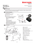
1400 Series Cable Reels
(142********* Cable, 145********* Welding, 146********* Grounding)
RECORD
The catalog number of the reel and the serial number
of the reel are required when ordering replacement
parts or discussing the reel with the factory. Please
record this information now in the spaces provided
below.
CATALOG NO. OF REEL: _____________________
SERIAL NO: ________________________________
DATE INSTALLED: __________________________
1.0 SAFETY
1.1
1.2
1.3
1.4
1.5
1.6
3.0 OPERATION
ELECTRICAL WARNINGS
OPERATIONAL WARNINGS
MAINTENANCE WARNINGS
UL/cUL RATINGS
ELECTRICAL RATINGS
LABELS & MARKINGS
4.0 MAINTENANCE
4.1
4.2
4.3
4.4
4.5
4.6
2.0 INSTALLATION
2.1
2.2
2.3
2.4
2.5
2.6
2.7
APPLICATION TYPES
MOUNTING (W/ OR W/O PIVOT BASE)
ROLLER GUIDE (W/ OR W/O FLOP OVER OPTION)
RATCHET
CABLE INSTALLATION
SPRING TENSION ADJUSTMENT
POWER CONNECTIONS
MAINTENANCE WARNING
LUBRICATION
INSPECTIONS
SLIP RING REPLACEMENT
CABLE REPLACEMENT
SPRING MOTOR REPLACEMENT
5.0 TROUBLESHOOTING
6.0 REPLACEMENT PARTS
6.1 EXPLODED VIEW
6.2 PARTS NUMBERS & ORDER FORM
www.insul-8.com
10102 F Street Omaha, NE 68127-1181 • 402/339-9300 • Fax 402/339-9627
• USA 800/521-4888 800/334-3283 CANADA •
P/N 962000 - Rev 2 - 1999.05.25
IOM 1400 Series Cable Reel
Page 1
INSUL-8 CORPORATION
The technical data and images which appear in this manual are for informational purposes only. NO
WARRANTIES, EXPRESS OR IMPLIED, INCLUDING WARRANTIES OF MERCHANTABILITY OR
FITNESS FOR A PARTICULAR PURPOSE, ARE CREATED BY THE DESCRIPTIONS AND
DEPICTIONS OF THE PRODUCTS SHOWN IN THIS MANUAL. Insul-8 makes no warranty (and
assumes no liability) as to function of equipment or operation of systems built according to customer
design or of the ability of any of its products to interface, operate or function with any portions of customer
systems not provided by Insul-8.
Seller agrees to repair or exchange the goods sold hereunder necessitated by reason of defective
workmanship and material discovered and reported to Seller within one year after shipment of such goods
to Buyer.
Except where the nature of the defect is such that it is appropriate, in Seller’s judgment, to effect repairs
on site, Seller's obligation hereunder to remedy defects shall be limited to repairing or replacing (at Seller's
option) FOB point of original shipment by Seller, any part returned to Seller at the risk and cost of Buyer.
Defective parts replaced by Seller shall become the property of Seller.
Seller shall only be obligated to make such repair or replacement if the goods have been used by Buyer
only in service recommended by Seller and altered only as authorized by Seller. Seller is not responsible
for defects which arise from improper installation, neglect, or improper use or from normal wear and tear.
Additionally, Seller’s obligation shall be limited by the manufacturer's warranty (and is not further
warranted by Seller) for all parts procured from others according to published data, specifications or
performance information not designed by or for Seller.
Seller further agrees to replace or at Seller's option to provide a refund of the sales price of any goods that
do not conform to applicable specifications or which differ from that agreed to be supplied which nonconformity is discovered and forthwith reported to Seller within thirty (30) days after shipment to the Buyer.
Seller's obligation to replace or refund the purchase price for non-conforming goods shall arise once Buyer
returns such goods FOB point of original shipment by Seller at the risk and cost of Buyer. Goods replaced
by Seller shall become the property of Seller.
There is no guarantee or warranty as to anything made or sold by Seller, or any services performed,
except as to title and freedom from encumbrances and, except as herein expressly stated and particularly,
and without limiting the foregoing, there is no guarantee or warranty, express or implied, of
merchantability or of fitness for any particular purpose or against claim of infringement or the like.
Seller makes no warranty (and assumes no liability) as to function of equipment or operation of systems
built to Buyer’s design or of the ability of any goods to interface, operate or function with any portions of
Buyer’s system not provided by Seller.
Seller's liability on any claim, whether in contract, tort (including negligence), or otherwise, for any loss or
damage arising out of, connected with, or resulting from the manufacture, sale, delivery, resale, repair,
replacement or use of any products or services shall in no case exceed the price paid for the product or
services or any part thereof which give rise to the claim. In no event shall Seller be liable for
consequential, special, incidental or other damages, nor shall Seller be liable in respect of personal injury
or damage to property not the subject matter hereof unless attributable to gross misconduct of Seller,
which shall mean an act or omission by Seller demonstrating reckless disregard of the foreseeable
consequences thereof.
Seller is not responsible for incorrect choice of models or where products are used in excess of their rated
and recommended capacities and design functions or under abnormal conditions. Seller assumes no
liability for loss of time, damage or injuries to property or persons resulting from the use of Seller's
products. Buyer shall hold Seller harmless from all liability, claims, suits and expenses in connection with
loss or damage resulting from operation of products or utilization of services, respectively, of Seller and
shall defend any suit or action which might arise therefrom in Buyer's name - provided that Seller shall
have the right to elect to defend any such suit or action for the account of Buyer. The foregoing shall be
the exclusive remedies of the Buyer and all persons and entitles claiming through the Buyer.
Page 2
IOM 1400 Series Cable Reel
P/N 962000 - Rev 2 - 1999.05.25
1.0 SAFETY
1.1 Electrical Warnings
1.1.1 Properly ground equipment before use
in accordance with both the National Electric
Code and local electrical codes and
ordinances.
1.1.2 Disconnect electrical power from the
cable reel before performing any service
functions.
1.1.3 Do not use cable reel for loads greater
than the current rating listed on the label and
voltage greater than 600V. The ampacity
(current) rating of the cable must be in
accordance with the National Electric Code.
1.1.4 Electrical wiring on the reel must be
done by a qualified electrician.
1.2 Operational Warnings
1.2.1 Exercise care when handling the cable
reel during normal operation. This cable reel
has a rotating spool powered by springs under
tension.
In the US call: 1-800-521-4888
1.3 Maintenance Warnings
1.3.1 Do not use cable different from that for
which the reel is intended.
Changes in
diameter, weight per foot, length of cable or
flexibility will affect the operation of the reel.
1.2.2 Do not disassemble the spring motor for
any reason. Serious personal injury could
result. This cable reel is equipped with springs
under tension.
Contact the factory for
assistance:
In Canada call: 1-800-667-2487
1.3.3 Overhead installation mountings should
be such that the reel is not suspended by
bolts in tension. A safety chain or cable is
strongly recommended to minimize damage
and/or possible injury in the event of mounting
failure.
1.3.2
Mounting hardware and fasteners
should be installed to maintain tightness under
vibration and checked periodically to assure
tightness.
WARNING: Modification of this
1.3.4
equipment may cause excessive wear and will
void the warranty. Contact the manufacturer
regarding changes or modifications of
equipment which could affect reliability or
safety.
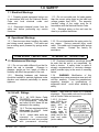
1.4 UL/cUL Ratings
means. They must be wired by a qualified
electrician. These cable reels are not provided
with a Feeder Cable and connector.
1.4.1 All 1400 Series Cable
POWEREEL products are built
to UL specifications. Reels that
are Listed UL/cUL Nema 4X are
indicated in the catalog.
1.4.2 The two requirements that
follow apply for UL/cUL listed
POWEREEL products:
1.4.2.1 Listed cable reels are
intended for commercial/
industrial use and are provided
with permanent mounting
P/N 962000 - Rev 2 - 1999.05.25
1.4.2.2 UL listed
type SOW-A or
SOOW-A, 600V,
rated 90°C or
105°C must be
used
for
the
supply cable (if
flexible cable is
used) and for the
load end cable
(active cable).
IOM 1400 Series Cable Reel
Page 3
SOW-A
1.5 Electrical Ratings
Cable:
AWG / # of Cond.
1.5.1 Reels Equipped with Cable
1.5.1.1 Reels equipped with cable are rated
based on the installed cable.
1.5.2 Reels Not Equipped with Cable
1.5.2.1 A cable reel that is not equipped with
flexible cable has a rating of 600 volts and
amperage per cable that is intended for use
with reel. See Table 1 for actual rating per
cable/conductor combinations.
1.5.2.2 Cables other than those listed in Table
1 must not exceed 35 amps/600 volts. Rating
must not be greater than the ampacity of type
and size of cable and the voltage rating not
higher than 600 volts. See Table 1 for
appropriate cable/conductor combinations.
16/2
16/3
16/4
16/5
16/6
16/7
16/8
16/10
16/12
14/2
14/3
14/4
14/5
14/6
14/7
14/8
14/10
14/12
(90°C) or
Ampacity
10.0
10.0
8.0
8.0
8.0
7.0
7.0
5.0
5.0
15.0
15.0
12.0
12.0
12.0
10.5
10.5
7.5
7.5
SOOW-A (105°C)
Cable:
AWG / # of Cond.
12/2
12/3
12/4
12/5
12/6
12/7
12/8
10/2
10/3
10/4
10/5
10/6
6/1
4/1
2/1
1/1
1/0/1
—
Ampacity
20.0
20.0
16.0
16.0
16.0
14.0
14.0
25.0
25.0
20.0
20.0
20.0
75
150
225
300
350
—
Table 1
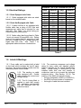
1.6 Labels & Markings
1.6.1 Every cable reel is marked with a label
on the base which includes the Insul-8 name
and logo, the product catalog number and the
individual product serial number.
1.6.2 The marking on cable
reels equipped with flexible
cable includes the current and
voltage ratings.
1.6.3 The UL Listing Mark is
applied to reels that comply
with applicable requirements
and are identified with the
authorized mark.
Page 4
1.6.4 The maximum amperage and voltage
rating for every cable reel supplied without
cable is stamped on the Insul-8 Identification
Label. Actual rating is determined by the
installed cable wire size and number of
conductors, and is not to exceed the indicated
maximum rating. (See Section 1.5.2.2.) The
marking of the cable reel should include:
• the type designation (SOW-A or SOOW-A)
• the AWG size and number of conductors
• the length of cable that was installed
IOM 1400 Series Cable Reel
P/N 962000 - Rev 2 - 1999.05.25
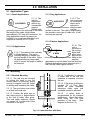
2.0 INSTALLATION
2.1 Application Types
2.1.1 Stretch Applications
2.1.3 Drag Applications
2.1.1.1 The
cable is
suspended
SUSPENDED
without any
intermediate
support.
Stretch reels
generally require a line pull equal to two times
the weight of the cable, which allows
approximately 10% sag at full extension. On
long applications where sag cannot be
tolerated, it is sometimes desirable to put
supports at intervals of 5 to 10 feet.
2.1.3.1 The
reel is mounted
SUPPORTED
on a stationary
object and is
required to
drag the cable
over the
surface to the reel. The cable is supported by
the ground or some type of cable tray. A ball
stop may be required.
2.1.4 Retrieve Applications
MOBILE
2.1.2 Lift Applications
2.1.2.1 The cable is lifted vertically
in lift applications. The reel is
normally designed to handle only
the total weight of the cable. Some
lift applications may require ball
stops to control the length of cable to
be retracted.
2.1.4.1 The
reel is
mounted on
the moving
FIXED
object and
4' MAX
winds up or
pays out the
cable as the
machine
approaches or moves away from the fixed end.
Retrieve applications can be elevated up to 4
feet from the cable support surface.
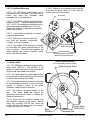
2.2 Mounting
2.2.1 Standard Mounting
2.2.1.4 If deflection is constant
to either side of the reel and
operation is impaired re-mount
the reel.
2.2.1.1 The reel may be mounted
by bolting the base to any flat
surface which is structurally sound
enough to support it and the forces
of winding and unwinding the cable.
2.2.1.2 The spool drum must rotate
on a level horizontal axis.
2.2.1.5 If the angle of deflection
exceeds 30° a Pivot Base
should be used, otherwise
excessive cable wear and
unreliable operation will result.
2.2.1.3 Position the guide arm so
that cable payout is perpendicular
to the face of cable roller guide.
The total cable deflection should
not exceed 15° to either side of the
centerline of the spool.
2.2.1.6
A safety chain is
recommended for all overhead
installations. Attach the safety
chain using the 0.39 hole
provided in the base.
(See
diagram for Section 2.3.)
Fig. 2.2 Cable Deflection with Roller
P/N 962000 - Rev 2 - 1999.05.25
IOM 1400 Series Cable Reel
Page 5
2.2.2 Pivot Base Mounting
2.2.2.1 All 1400 Series Cable Reels can be
furnished with a pivot base to allow the reel to
rotate and keep the extended cable
perpendicular to the application.
2.2.2.6 Selection of mounting holes should be
such that the spool center is in line with the
center point of the pivot base.
Fixed Pivot Stop
Traveling Pivot Stop
2.2.2.2 The PVB Pivot Base has the ability to
rotate up to 345°. Travel can be limited to 90°,
180°, or 270° by installing an additional roll pin
in the appropriate available hole. This Pivot
Base is not suitable for applications requiring
continuous rotation.
(X3)
2.2.2.3 A pivot base is required in carousel or
loop-track applications.
2.2.2.4 When a pivot base is used, the
reel must be mounted horizontally
("ceiling" or "floor" mounted).
PC (6” Drum W idth)
PA (3” Drum W idth) &
PB (4.5” Drum Width)
2.2.2.5 The Roller Guide should be mounted
so the cable will travel perpendicular to the
axis of rotation. This will guard against the
cable twisting and ensure effective swivel
action from the pivot base.
Key Mounting Holes
(Key Mounting Hole on Pivot Base is
cham fered for easy identification)
Roller Guide Locations
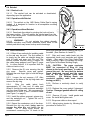
2.3 Roller Guide
4 of 12 possible positions shown.
2.3.1 All 1400 Series units are equipped with a
roller guide (PR87-#). The function of the
guide is to center the cable on the spool and to
help the reel wrap cable more evenly.
Sh aft C ou p ling : P R 47
2.3.2 The cable should not bear against either
end of the spool during winding as this will tend
to inhibit level winding of the cable.
2.3.3 The guide should be secured at the best
of twelve possible positions so that a minimum
change of direction occurs at the guide;
otherwise, cable life will be reduced.
2.3.4 The guide is shipped installed on the
reel.
The guide must be aligned per
application and secured prior to making any
electrical connections.
2.3.4.1 Mount the roller guide to the reel over
the entrance coupling on the frame. Secure
using the provided 5/16-18 hex head cap
screw, including the spring-type lock washer.
Torque this screw to 15 ft-lbs.
B ase:
PR 04A -2
Page 6
IOM 1400 Series Cable Reel
Safety C hain
M o un ting H ole
R o ller G u id e
P R 87-[3,4,6]
P/N 962000 - Rev 2 - 1999.05.25
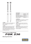
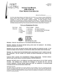
2.3.5 Flop-Over Guide Arm Kit (Part Number FGK)
(Numbers in paragraphs refer to Figure 2.3.5 and to Replacement Parts Order Form.)
2.3.5.1
Note: The Flop-Over Guide Arm
Accessory Kit is appropriate for 2-way payout
applications requiring a roller guide when a
pivot base is not appropriate.
2.3.5.2 Before installing, be sure the power is
off.
11
16
15
2.3.5.3 Disconnect the cable that provides
power to the reel, if installed.
2.3.5.4 Remove the original shaft coupling
(PR47) and replace with the grooved shaft
coupling, Item 15.
17
2.3.5.5 Make sure the grooved side of the
shaft coupling is nearest the base, Item 11.
8
2.3.5.6 Tighten the shaft coupling to 30-40 ftlbs. torque.
2.3.5.7 Place one thrust washer, Item 16, on
the shaft coupling and locate it flush against
the base.
2.3.5.8 Position the guide arm, Item 8, on the
shaft coupling.
2.3.5.9 Slip the radial bearing strip, Item 17,
between the shaft coupling and the guide arm.
Trimming may be required.
16
18
Figure 2.3.5
2.3.5.10 Locate the second thrust washer,
Item 16, on the shaft coupling.
2.3.5.11 Secure the assembly with the snap
ring, Item 18.
2.3.5.12 Re-connect the supply cable.
P/N 962000 - Rev 2 - 1999.05.25
IOM 1400 Series Cable Reel
Page 7
2.4 Ratchet
2.4.1 Ratchet Lock
2.4.1.1 The ratchet lock can be activated or deactivated,
depending upon the application.
2.4.2 Operation with Ratchet
2.4.2.1 The ratchet on the 1400 Series Cable Reel is spring
loaded. It is designed to function in all acceptable mounting
configurations.
2.4.3 Operation without Ratchet
Activated
2.4.3.1 Deactivate the ratchet by pivoting the lock-out bar to
the lower position. This will remove the ratchet pawl from the
path of the ratchet plate. Locate the dimple on the lock-out bar
in the hole provided.
2.4.3.2 WARNING: Do not activate the ratchet abruptly.
Sudden activation may cause excessive shock loads to the
ratchet pawl which may cause lock-up and/or breakage.
2.5 Cable Installation
2.5.1 Either of two methods for installing cable
on the reel may be used. The first method is
to simply lay the cable out straight along the
path of travel and wrap onto the reel. The
second method requires using a support for
the cable being wrapped (see Figure 2, page
9). In either method, it is important that the
cable not twist or loop.
2.5.2 Remove the (6) nuts securing the slip
ring cover.
Remove cover and gasket.
Reinstall the nuts finger tight to hold the flange
in place.
2.5.3 Loosen the set screw(s) (1/8" Allen
Wrench) at the base of the slip ring stack and
remove the slip ring.
2.5.4
Strip the cable jacket back
approximately 10" from end of cable and
thread it through the cable entrance watertight
into the drum of the reel. We recommend a
cable-tie on 16 AWG, 2 and 3 conductor cable
(see Figure 1 on page 9).
2.5.5 Install the rubber grommet, gripper ring,
and the watertight nut. Tighten the nut to
secure the cable.
2.5.6 Extend the conductors out of the drum.
Reinstall the slip ring stack, being sure to
engage the drive pin, and tighten the set
screws.
On 6" deep spool drums, we
recommend connecting the 1-6 leads to the
Page 8
Deactivated
brush post terminal before installing the ring on
the shaft. (See Sections 4.4 and 4.5)
2.5.7 Strip and insert cable leads into the
appropriate brush post terminals and tighten
screws. (See page 9 for Color Code Chart
used by factory. Figure 3 illustrates Slip Rings,
and Figure 3a illustrates Welding Rings.)
2.5.8 CAUTION: The green conductor
MUST be connected to Ring #1 (ring
closest to the brush post base) in order to
ground the reel. Be sure that the bottom
brush (dedicated ground) and the green
wire at the top terminal block have
continuity.
(On Welding Reels, one
conductor welding cable ends require
tinning per NEC.)
2.5.9 Perform a continuity check to verify
circuits.
2.5.10 Replace the cover gasket if damaged.
Caution: Damaged gaskets affect UL rating
of reel.
2.5.11 Remove (6) nuts. Install gasket and
cover. Re-install and tighten nuts.
2.5.12 Wrap new cable on drum spool.
2.5.13 Adjust spring tension by following the
procedure in Section 2.6.
IOM 1400 Series Cable Reel
P/N 962000 - Rev 2 - 1999.05.25
COLOR CODE CHART
Cond.
No.
Base
Color
Tracer
Color
Cond.
No.
Base
Color
Tracer
Color
1
Green
--
7
White
Black
2
Black
--
8
Red
Black
3
White
--
9
Green
Black
4
Red
--
10
Orange
Black
5
Orange
--
11
Blue
Black
6
Blue
--
12
Black
White
Leave 1/4"
from End
of Cable
Jacket to
Cable-Tie
Cable-Tie on Cable
(For 16 AWG, 2 & 3 cond.)
To Slip Ring
in Drum
Watertight
Figure 1
Ratchet
Teeth
Cable
Entrance
Figure 2
Inside (Back)
Flange
Grounding Ring
Terminal
Spool Drum
Proper Drum Orientation
Figure 4
Spool Cable
Terminal
Spool Cable
Termination
Set-screw
Feeder Cord
Set-screw
Brush Post
Terminal Block
Feeder Cord
Terminal
Service Leads
Service Cable
(On Spool; Up To
12 Conductors )
P/N 962000 - Rev 2 - 1999.05.25
Cable Reel Ring
Drive Collar
Set-screw
Figure 3
IOM 1400 Series Cable Reel
Welding Ring
Figure 3a
Page 9
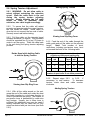
Adding Spring Tension
2.6 Spring Tension Adjustment
2.6.1 WARNING: Do not allow cable to
retract without restraining the retraction
speed. Walk the cable back to the reel
during the spring tension adjusting
process. Always maintain two full cable
wraps on drum at maximum cable
extension, size cable length accordingly.
2.6.2 To assure that the cable will retract
properly and operate under the correct tension,
the reel should be tested. Install cable on
drum but do not connect the free end of cable.
Securely mount reel before testing.
2.6.3 Pull the cable out the intended travel
distance and allow it to rewind. This procedure
should be repeated five (5) to ten (10) times in
order to set the spring. Walk the cable back
to the reel during the spring tension adjusting
process.
Rotate Spool while holding Cable
to test the Spring Tension
Viewing from Slip Ring Cover
2.6.5 Feed the end of the cable through the
cable guide and pull the cable out the required
Note: Total number of spool
length.
revolutions, including pre-tension turns, must
not exceed the limits in the following table:
Spring model designation stated in reel description on invoice and packing slip.
No. of Models Motor # No. of Models Motor #
Turns
w/#
Turns w/#
23
J
PR89
30
K
35001
23
JP
PR89P
30
KP
35002
46
JS
PR89S
60
KS
35003
Consult the factory or your representative if
number of spool turns is not within parameter.
Viewing from Slip Ring Cover
2.6.6
Repeat steps 2.6.3
to 2.6.5,
if
necessary, to add tension.
To decrease
tension, rotate drum and cable counterclockwise.
Adding Spring Tension
2.6.4 With all the cable wound on the reel,
grasp the end of the cable and rotate the drum
and cable together in a clockwise direction in
order to pre-tension the spring. The number of
pre-tension turns is determined by cable size
and footage. Usually, two to three turns is
sufficient, but additional turns may be used if
testing indicates that the cable will not fully
retract as desired with just two turns (see Note
2.6.5).
Page 10
IOM 1400 Series Cable Reel
P/N 962000 - Rev 2 - 1999.05.25
2.7 Power Connections
(For Welding Reels See Section 2.5
and Figure 3a.)
2.7.1 Provide power source with over-current
protection to prevent overheating of the reel
and cable.
2.7.5 If a supply cable entrance watertight is
used, be sure gland size is correct for cable
diameter. Tighten to seal and to prevent cable
pullout. The watertight needs to have 1" NPT
thread.
2.7.2 Connect the supply cable to the terminal
ring at the top of the slip ring. Wire according
to Color Code Chart on page 9.
2.7.2.1 Be sure the GREEN (ground) wire is
connected to the green wire slip ring using the
top terminal block.
2.7.3 Slide the supply cable back through the
shaft to eliminate excess slack at the terminal
block. Failure to do so may cause Ring to
short out due to excessive wear on insulation
of the supply lead(s).
2.7.4 Be sure the supply leads will not come
in contact with the slip ring cover or the reel
shaft.
3.0 OPERATION
3.1 Do not exceed the voltage or amperage
rating of the cable. Overheating, fire, damage
to equipment or personal injury could result.
3.2 Do not allow cable to retract without
restraining retraction speed.
3.3 Operate the reel within the cable size and
length and spring tensioning limits for which it
was intended.
3.3.1 Keep two wraps of cable on the reel at
maximum extension to avoid excessive tension
on the cable and to prevent pullout of cable
from entrance watertight.
3.3.2 The spring should not be wound to the
last two turns at maximum payout to avoid
over-stressing the spring(s), thus reducing its
life or damaging the reel.
3.4 Keep the reel and cable clean to avoid
excessive wear and damage.
3.5
Arrange for maintenance service if
damage is found on the cable or reel.
3.6 Cable should be fully retracted when not
in service to maximize spring life.
4.0 MAINTENANCE
4.1 WARNING: Be sure power is off for maintenance.
4.2 Lubrication
4.2.1 All components requiring lubrication are
lubricated for life at the factory. Additional
lubrication is not required.
P/N 962000 - Rev 2 - 1999.05.25
4.2.2 Do not apply any lubricants or solvent
cleaning agents to slip ring, brush or insulator
surfaces.
IOM 1400 Series Cable Reel
Page 11
4.3 Inspections
4.3.1 Periodically check the reel for any loose
or missing fasteners. Tighten or replace as
necessary.
4.3.3 Inspect cable for damage or wear which
would make it unsafe to use.
4.3.2 The slip ring assembly should be
checked periodically as follows:
Brush Spring
4.3.2.1 Clean to remove dust and dirt from
the slip ring housing area and all slip ring
assembly and brush surfaces.
Brush
4.3.2.2 Brushes should be centered on slip
rings and brush springs should be seated in
terminal post grooves.
Terminal screw
connections should be tight. Check for
excessive brush wear. Replace brushes as
necessary.
Replace
Brush
@ 0.09”
Insulator
4.4 Slip Ring Replacement
4.4.1
The slip ring assembly should be
replaced, not rebuilt, if it becomes damaged.
4.4.3
Carefully and thoroughly clean the
inside of the reel drum and the slip ring cover.
4.4.2 Follow steps 4.5.5 through 4.5.8 to
remove the slip ring assembly.
4.4.4 Follow steps 4.5.5 through 4.5.8 in
reverse order to install the new slip ring stack.
Spool Cable &
Brush Terminals
Drive Pin PR60
(Not used with Welding Reel models)
Drive Pin Engagement Hole
(Not found on Welding Reel models)
Brush Post
Base
Supply Cable Connections
Set-Screw(s)
Spool Cable
Terminal
Cable Entrance
Watertight
PR90-(1, 3, 5)
Slip Ring
PR35-(1, 2, 3, 4, 6, 8, 10, or 12)
Set-Screws
Model 145********* Welding Reel Ring Version
Part #41182
Page 12
IOM 1400 Series Cable Reel
P/N 962000 - Rev 2 - 1999.05.25
4.5 Cable Replacement
4.5.1 Replacement cable should be the same
size and length as existing cable. Any variations to cable specifications should be preapproved by the factory.
4.5.2 Disconnect all electrical service to the
reel before replacing the cable. Follow LockOut/Tag-Out procedures as outlined by OSHA.
4.5.3 Disconnect the terminal outboard end of
the cable and allow cable to retract onto spool.
Ensure all spring tension is off by manually
rotating the spool.
4.5.4 Remove the cable from the spool by
looping it over the spool flange and slip ring
cover. Make sure the cable end is through the
cable guide.
4.5.5 Remove the six (6) nuts holding the slip
ring cover. Remove cover and gasket. Reinstall the nuts finger tight to hold the flange in
place.
4.5.7 Loosen the brush post terminal screws
(set-screws on Welding Reel Ring) and release the cable leads.
4.5.8 Use 1/8" Allen Wrench to loosen the set
screw(s) and remove the slip ring stack.
4.5.9 Remove the watertight nut, gripping ring,
bushing and the cable to be replaced.
4.5.10 Obtain the replacement cable of the
correct size and length and strip the cable end
to match the old cable.
4.5.11 Carefully and thoroughly clean the
inside surfaces of both flanges and the drum.
4.5.12 Follow instructions 2.5.4 through 2.5.13
to install the replacement cable, taking care to
avoid twisting the cable while winding it onto
the reel. Care should also be taken to match
the color coded cable leads. (For additional
information on wiring, see Section 2.7 Power
Connections.)
4.5.6 Loosen the supply cable terminal screws
(set-screws on Welding Reel Ring) and release the supply cable leads from the terminal
block of slip ring.
by
4.6.7
Remove the spring motor
unscrewing the shaft from the mounting base.
4.6 Spring Motor Replacement
4.6.1 CAUTION: Do not open the spring
motor or personal injury may result.
4.6.2 The spring replacement process is
determined by the spring configuration and
cannot be performed in the field. The entire
spring motor assembly must be replaced as a
unit.
4.6.3 Disconnect all electrical power to the
reel before beginning any maintenance or
service.
4.6.4 Remove the slip ring from the shaft by
following the procedure outlined in Section 4.4.
4.6.5 Remove the (4) nuts in the bottom of the
drum.
This may require removing the
watertight in order to access all nuts. Lift the
cable, drum, and front flange together and set
aside.
4.6.6 Remove the shaft coupling.
P/N 962000 - Rev 2 - 1999.05.25
4.6.8 Remove packing material from the
replacement spring motor and attach it to the
mounting base.
4.6.9 Re-assemble spring reel in reverse
order with the new spring motor. Note the
following:
A. Ratchet must be in the deactivated position
(see figure for Section 2.4).
B. Shaft must be fully seated on base before
installing coupling and watertight.
C. Reactivate ratchet to ensure proper
alignment.
D. Verify drum and ratchet teeth orientation
per Figure 4, page 9.
4.6.10
Install cable by following the
instructions in Section 2.5.6 through 2.5.11;
refer to Figure 2, page 9.
4.6.11 Adjust spring tension by following the
procedure in Section 2.6.
IOM 1400 Series Cable Reel
Page 13
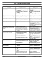
5.0 TROUBLESHOOTING
PROBLEM
Reel will not retract cable but has
some tension.
POSSIBLE CAUSE
1) Improper pretension.
2) Incorrect reel for application (lift
vs. stretch).
3) Improper cable or cable length
installed.
4) Cable guide adjustment.
SOLUTION
1) See Sec. 2.6 Spring Tension
Adjustment.
2) Quantify application vs. reel
selection.
3) Install correct cable type and
length.
4) Check guide alignment (see
Sec. 2.2 and 2.3).
Reel does not have any spring
tension.
1) Broken spring. *Quantify applica- 1) Replace spring motor (see Sec.
tion to prevent recurrence.
4.6).
Ratchet will not activate.
1) Broken ratchet pawl spring.
1) Replace ratchet pawl spring.
2) Lock-out option arm deactivated. 2) Activate lock-out arm (see Sec.
2.4).
Ratchet will not deactivate.
1) Over-extension of reel.
1) Manually rotate reel spool to
deactivate ratchet. Do not
over-extend. (Guide adjustment may prevent lock-up when
over-extended.)
Cable wraps improperly (uneven
wrapping, wraps above or jumps
flange).
1) Reel mounting not level.
2) Cable retraction rate too high.
3) Cable guide out of adjustment.
1) Mount reel on level surface.
2) Maintain steady retraction rate.
3) Properly adjust cable guide
(see Sec. 2.2 and 2.3).
4) Install correct cable type and
length (see Sec. 1.5 and 2.5).
4) Improper cable or cable length
installed.
Cable twisting or knotting.
1) Improperly installed cable.
2) Cable rubbing on or bending
around fixed object.
3) Excessive spring tension.
4) Inadequate anchoring of cable.
1) See Sec. 2.5 Cable Installation.
2) Check roller guide for function
and cable payout path (see
Sec. 2.3).
3) Quantify application vs. reel
selection. Also check pretension.
4) Adjust anchoring method. i.e.
add strain relief.
Open or intermittent circuit.
1) Inadequate connection.
1) Check all termination points.
2) Loss of brush contact to slip ring. 2) Check brush wear, spring
tension & alignment.
3) Perform continuity check on
3) Cable defective.
cable termination points.
Circuit trips and/or Pitted burned
rings or brushes.
1) Inadequate amp rating of reel
selection.
1) Quantify application requirements vs. reel & cable rating
(see Sec. 1.5).
Circuit arcing
1) Amp or voltage above rating of
reel.
1) Quantify application requirements vs. reel & cable rating
(see Sec. 1.5).
2) Clean dust from inside slip ring.
2) Excessive carbon dust accumulation.
3) Water or moisture in slip ring.
4) Loss of brush to ring contact.
Page 14
IOM 1400 Series Cable Reel
3) Check gasket seal.
4) Replace brush and/or brush
spring.
P/N 962000 - Rev 2 - 1999.05.25
P/N 962000 - Rev 2 - 1999.05.25
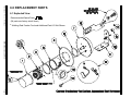
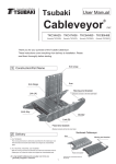
6.0 REPLACEMENT PARTS
6.1 Exploded View
Recommended Spare Parts: 7 12
(All parts are factory stock items.)
* Welding Reel Feeder Cord and Additional Part #13 Not Shown
IOM 1400 Series Cable Reel
Page 15
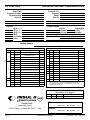
6.2 Order Form
1400 Series Cable Reel - Replacement Parts
Order Date:
Customer Contact:
Requested Ship
Sold To:
Customer P.O.:
Signature
Phone:
Ship To:
Ship Via:
Freight Charges:
UPS (Surface)
UPS (2nd Day)
UPS (Next Day)
MTR
Air Freight
Other
Collect
Allowed
3rd Party
Prepay/Add
C.O.D.
Pick-Up
(Carrier)
Tax Exempt No.:
Catalog Number:
Components
Components
Item
1
2
QTY
4
Description
Description
PR13-3
3" Slip Ring Cover
5
PR08
Front Flange
PR13-4
4" Slip Ring Cover
6
PR57
Cable Drum Gasket
PR13-6
6" Slip Ring Cover
7*
8" Slip Ring Cover
PR35-01
01 Conductor Ground Ring
8
**
Spring Motor
PR87-3
Guide Arm for 3" Drum
PR87-4
Guide Arm for 4" Drum
PR87-6
Guide Arm for 6" Drum
Price
PR35-03
35 AMP 03 Conductor Slip Ring
PR35-04
35 AMP 04 Conductor Slip Ring
9
PR47
Shaft Coupling
PR35-06
35 AMP 06 Conductor Slip Ring
10
PR91
Ratchet Repair Kit
PR35-08
35 AMP 08 Conductor Slip Ring
11*
PR04A-2
Base Assembly (PR91 Included)
12
PR95
Individual Brush & Brush Spring
PR90-1
Cable Kit for OD Cable 0.31"-0.56"
PR90-3
Cable Kit for OD Cable 0.5"-0.75"
PR90-5
Cable Kit for OD Cable 0.7"-0.95"
03688
Cap Plug (4" & 6" Drum Only)
PR35-10
35 AMP 10 Conductor Slip Ring
PR35-12
35 AMP 12 Conductor Slip Ring
41182
3
P/N
P/N
PR13-8
Price
Item QTY
450 AMP 01 Conductor Weld Ring
PR55
Cover Gasket
PR86-3
3" Cable Drum
PR86-4
4" Cable Drum
PR86-6
6" Cable Drum
13
14
*Note: Items 7 & 11 must be purchased as a set for units
manufactured before 3/96. ** Consult factory for actual
Part Number you require.
Flop-Over Guide
(See Figure 2.3.5, Page 7)
Items
Qty
15-18
USA:
www.insul-8.com
10102 F Street • Omaha, NE 68127 • USA
Page 16
Canada:
IOM 1400 Series Cable Reel
P/N
Description
FGK
Flop-Over Guide Kit
FAX To:
(402) 339-9627
(24 HRS)
Voice Verify:
(800) 521-4888
(Central)
FAX To:
(450) 432-6985
(24 HRS)
Voice Verify:
(800) 667-2487
(Eastern)
P/N 962000 - Rev 2 - 1999.05.25