1
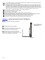
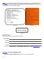
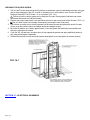
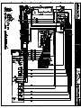
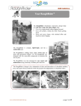
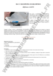
PASSPORT™ Residential Vertical Platform Lift (VPL) Installation Manual Manufactured in the USA © 2012 Homecare Products, Inc. All rights reserved. All text and images contained in this document are proprietary and may not be shared, modified, distributed, reproduced, or reused without the express written permission of EZ-ACCESS®, a division of Homecare Products, Inc. PN 12274 REV 06-03-2013 ATTENTION INSTALLER – VERIFY PRIOR TO INSTALLATION: Check for shipping damage immediately upon receipt. Note any freight damage on freight bill while driver is still present. In most cases, freight damage claims will not be allowed unless noted on the freight bill. Pictures of damage before the unit is unpacked can be very helpful. Contact shipper right away with any freight damage concerns. The VPL is shipped with a packing list. Ensure all items are present before starting installation. Layout installation site taking into consideration VPL entry and exit points, height, and electrical supply location. The VPL platform must be at least 3/8” but no more than 3/4” from the edge of the upper landing (horizontally). The VPL platform guard walls must be at least 2” but no more than 3” (horizontally) from walls or other obstructions. It is the installer’s responsibility to verify local codes and regulations regarding power supply and electrical connections. The VPL is supplied with a 12’ power cord. The VPL must be anchored to a level, 3,500 PSI concrete pad at least 4” thick. The minimum pad dimensions are 41” x 50” to anchor the legs and support the tower. However, a larger pad will be needed if it is desired that the guard ramp land on the pad and/or the approach to the ramp be incorporated into the pad. Final pad location, orientation and dimensions are the installer’s responsibility to determine based on field conditions. Confirm the structural integrity of any existing fascia. Verify that the upper landing area is level. Determine which side of the VPL the guard ramp will be attached to and make sure there is adequate clearance at the lower landing to access the ramp. Check for adequate headroom clearance above VPL platform. The 52” VPL requires approximately 100” to travel to its maximum height not including the occupant. Verify adequate running clearances for the VPL. The platform must be able to travel up and down and the guard ramp must be able to fold and unfold without interference or obstruction. Refer to the Top Landing Gate Placement and Installation section if installing a Top Landing Gate. Read and understand the entire Installation Manual before proceeding with installation. Please leave User Manual with the VPL user. TABLE OF CONTENTS Section 1 - - - - Symbols, Safety and Warnings Section 2 - - - - Labeling and Dealer Contact Information Section 3 - - - - Optional Equipment Notice Section 4 - - - - Assembling the VPL Section 5 - - - - Optional Equipment - Wireless Remote Section 6 - - - - Optional Equipment - Top Landing Gate Section 7 - - - - - - - Top Landing Gate Optional Equipment - Pathway Connector Kit Section 8 - - - - - - - Top Landing Gate Optional Equipment - Deck Connector Kit Section 9 - - - - Optional Equipment - Platform Safety Rail Section 10 - - - - Optional Equipment - Platform Safety Pan Weather Guard Section 11 - - - - Optional Equipment - Interlock Section 12 - - - - Optional Equipment - Call/Send Control Section 13 - - - - - - - Call/Send Control Optional Equipment - Call/Send Control Mounting Kit Section 14 - - - - Maintenance and Service Section 15 - - - - Electrical Drawings See User Manual ---Features ---Operation ---Emergency Operation ---Specifications ---Troubleshooting ---Main Components Drawing and Overall Dimensions (52” VPL) ---Warranty Page | 2 SECTION 1 - SYMBOLS, SAFETY AND WARNINGS SYMBOL MEANINGS This is the WARNING symbol. This symbol may appear in various colors and in conjunction with other symbols. The WARNING symbol indicates a failure to obey that safety warning could result in property damage, damage to equipment, serious personal injury or death as well as the serious personal injury or death of others. This is the NOTE symbol. This symbol may appear in various colors and in conjunction with other symbols. This indicates a failure to obey all notes could result in improper operation, less than optimum VPL performance, and at the sole discretion of the VPL manufacturer, may void your warranty. SAFETY WARNINGS: The safety warnings throughout this manual are for the protection of people and property. Failure by any operator to obey all VPL safety warnings will result in a waiver of all liabilities, loss of your warranty and could result in equipment damage and or failure, injury to property, risk of serious bodily injury, and or death. Read the User Manual in its entirety. Understand and learn the location and function of all the features, safety devices, and labels before operating the VPL. Do not exceed the weight capacity of 750 pounds (340 Kg.) for this VPL. Do not use VPL for anything other than its intended purpose. VPL is intended for personal residential use for lifting of individuals and personal mobility devices. Keep all body parts away from moving components and within the platform guards during VPL operation. The Platform Safety Rail option must be installed if the VPL is used by a standing occupant. Do not play on or near the VPL. Turn off power and engage the brake on all mobility devices prior to cycling the VPL. Remove ice, snow, leaves and other potentially unsafe or obstructing materials from VPL and landings before each use. Inspect your VPL for damaged, missing, or inoperable parts before each use. Do not use VPL if it is damaged or unstable. Periodically check all fasteners and verify all nuts, bolts, screws and other fasteners are undamaged and secure. Do not attempt to repair or modify the VPL. Only qualified technicians may service the VPL. Contact your dealer to schedule any needed inspections, repairs or service. Observe and avoid all pinch points. Whenever not actively using the VPL, turn keyed power switch to “OFF” position and remove key. Always unplug VPL from electrical outlet before cleaning. Only plug the VPL back in when the area around the VPL is dry. Do not operate VPL with damaged electrical wires, cords, or plugs. The AC electrical plug on this VPL is grounded and intended to be used only with a properly grounded AC outlet. Do not remove ground pin from AC power cord. If ground pin is broken or missing, immediately contact your dealer to schedule repairs. Stop using VPL and immediately contact your dealer if any defect is suspected or found and to schedule any needed inspections, repairs or service. Do not tamper with or attempt to modify the VPL or any of its systems. Use VPL only with a qualified helper, if required. Do not use the VPL to support, attach, or hang planters, baskets, lights, adornments, decorations, clothing, fabrics or other ornamentals or furnishings. Components inside the tower must be serviced by a qualified technician. Contact you dealer to schedule any needed inspections, repairs or service. Periodic inspections by a qualified technician are recommended to help prevent unsafe conditions. The VPL’s electrical cord must be routed and situated in a manner that poses no hazards. Do not lay power cords on or across electrically conductive materials, such as metals and always route power cords in such a manner so no one can trip over them and that they are not exposed to risk of accidental or incidental damage. Before and while operating VPL, ensure all hair, jewelry, shirts, ties, shoe laces, coats, aprons, dresses, pants, and all forms of clothing and other personal ornamentation are-not and do-not hang up on anything that may create a hazard. Correct installation, proper use, and following of instructions and obeying safety warnings and of the VPL are necessary for safe operation. If service outside the guidelines of this manual is required, please contact your dealer for additional information, for replacement labels and manuals or to schedule any needed inspections, repairs or service. Page | 3 VPL must be anchored to a concrete slab before operating the VPL while it is occupied. Using the VPL while occupied before installation can be hazardous. Maintaining all labels and manuals in legible condition is required by the VPL owner and is essential for safe VPL operation. The VPL comes with various product safety labels. Do not remove safety labels or devices. If any labels are missing, damaged or become illegible they must be replaced. An illegible decal will fail to alert individuals on or around the machine of a procedure or hazardous operating conditions. Contact your dealer for additional information, replacement labels and manuals or to schedule inspections, repairs or service. For proper warranty coverage, fill out and return the included warranty form. Keep all panels and protective coverings in place. The VPL warranty is not transferable. Attempting to tamper with or modify any portion of the VPL will void your warranty. Except as described elsewhere in this manual, maintenance must only be performed by qualified technicians. Contact your dealer to schedule any needed maintenance, inspections, repairs or service. Caustics, high alkaline detergents and solutions should not be used to clean aluminum. Using this VPL for anything other than its intended purpose will void the warranty. SECTION 2 – LABELING AND DEALER CONTACT INFORMATION Assure all labels are present and legible. VPL Safety labels come pre-installed. Each VPL should have labels positioned on the VPL as illustrated in the image to the right. The labels shown at right are for illustrative purposes only. Labeling on your particular VPL may differ in color, boarders, size, and content. FIG. 2.1 Page | 4 FIG. 2.2 is a typical VPL Serial Number Label. Assure the Serial Number Label is present and legible on each VPL. FIG. 2.3 is a condensed version of the VPL Standard Safety Label that comes on each VPL. The VPL Standard Safety Label includes standard safety information as well as safety information on VPL Options. Your particular lift may, or may not, have these Options. FIG. 2.2 FIG. 2.3 FIG. 2.4 DEALER CONTACT Contact dealer with questions and for additional information. DEALER NAME: ADDRESS: TELEPHONE: INTERNET: If you need additional assistance, please or call one of the numbers below. Customer Service: 1-800-451-1903 Technical Support: 1-800-332-1381 Internet: www.ezaccess.com. SECTION 3 - OPTIONAL EQUIPMENT NOTICE VPL OPTIONS ARE SOLD SEPARATELY. Options do not come with a Standard VPL. Page | 5 SECTION 4 - ASSEMBLING THE VPL 1. Remove the power head cover first by removing the two button head bolts on either end (FIG. 4.1). 2. Remove front and rear tower covers. The fully assembled VPL weighs approximately 380 lbs. To make assembly easier, the unit can be assembled a few inches away from its final position and repositioned as required. FIG. 4.1 3. The guard ramp activating bar comes installed on the VPL. If it is not on the side where the guard ramp will be installed, remove the two button head bolts that hold it in place and re-install on the opposite side. The guard ramp activating bar must always be installed on the same side as the guard ramp. 4. Attach the platform assembly to the carriage by first removing the attachment nuts and bolts from the carriage side plates. Lift the platform assembly onto carriage engaging both 1½” square tubes on the platform to the corresponding hooks in the carriage and reinstalling the nuts and bolts to secure the platform assembly to the carriage (FIG. 4.2). The outer cable clamp holding the control box wire bundle may need to be removed from the carriage to fully engage the platform tubes. Page | 6 FIG. 4.2 5. Locate the wiring connector protruding from the back of the platform and attach to the corresponding connector on carriage (FIG. 4.3). FIG. 4.3 Page | 7 6. Remove guard ramp pivot plates (FIG. 4.4a) from the platform. Locate the guard ramp and ramp spacer tubes then slide the pivot plates and spacer tubes over the ramp torque tubes as shown (FIG. 4.4b) FIG. 4.4a FIG. 4.4b 7. Position the guard ramp with pivot plates on the entry side of the platform and secure both pivot plates to the platform with the bolts removed in the previous step. 8. Install the pivot arm assembly by first removing the bolt and nut from the pivot arm (FIG. 4.5). a. Slide the pivot arm into the torque tube on the guard ramp until the bolt holes align. b. Secure with the bolt and nut removed previously. c. Verify that the roller is positioned beneath the guard ramp activating bar. The roller will contact activating bar when operated. Avoid pinch points! Page | 8 FIG. 4.5 9. Install the guard walls with smooth side toward inside of platform as shown (FIG. 4.6). a. Loosen the two set screws in each platform corner pocket as needed to fully engage the guard wall posts and tighten all set screws securely after the guard walls are installed. Make sure guard wall with two holes in top rail is installed closest to the tower as shown (FIG. 4.7). FIG. 4.6 Page | 9 FIG. 4.7 10. Install control box mounting frame to rear guard wall by first removing nuts and bolts from control box mounting frame posts (FIG. 4.8). a. Install the mounting frame between the guard wall and tower with the nuts and bolts oriented as shown and tightened securely. FIG. 4.8 11. The control box is secured to inside of tower with zip ties. Locate and cut the zip ties to free the control box (FIG. 4.8). a. Remove fasteners securing mounting channels to control box. b. Position control box into the mounting frame as shown and reinstall the mounting channels using the fasteners removed in the previous step. c. Check to make sure that the control box is free to slide entire length of mounting frame. CONFIRM BASIC VPL OPERATION 1. The batteries are fully charged when VPL is shipped. The batteries will maintain their charge for approximately two months under normal conditions. 2. The VPL can now be operated to confirm basic function. Do not operate the VPL while occupied until it is anchored in place. 3. Page | 10 Since the cover panels have not been reinstalled, the lift mechanism will still be exposed at this point. Be sure to keep all body parts and loose clothing, as well as other people and pets, clear of the VPL to avoid potential injury. Slide control box to one side so the VPL can be operated while standing on the ground. 4. 5. 6. 7. 8. 9. 10. 11. 12. Verify that the keyed switch on the control box is in the Power “OFF” position. Do not plug VPL into 120 volt outlet at this time. The VPL is shipped with the white wire which connects to the negative battery terminal disconnected. Without standing on the platform, locate and reconnect the wire (there should only be one open terminal on the batteries) (FIG. 4.9). The VPL should not operate when the wire is connected to the battery as long as the keyed switch is the Power “OFF” position. However, in case of unexpected operation, be sure you are positioned to prevent injury in case the VPL operates accidentally when the wire is connected. A small amount of sparking is normal when connecting the wire. While standing on the ground, not on the platform, turn the keyed power switch to the Power “ON” position. The power indicator on the control box should illuminate. Press the UP button. The VPL should immediately operate in the upward direction. The UP indicator should illuminate continuously. The Obstruction indicator will illuminate briefly until the platform has traveled upward one or two inches then should go out. Run the VPL up approximately 12” and release the UP button to stop upward travel. Press the Down button. The platform should travel downward and the DOWN indicator light should illuminate continuously. Continue to run the platform down until the VPL stops. The VPL should stop at the bottom of its travel automatically. The Obstruction and the Enter/Exit indicators should be illuminated when the platform reaches the bottom of its travel and stops. Run the VPL up to about 12” again. Actuate the safety pan under the platform and press the DOWN button simultaneously. The VPL should stop its downward travel and the Obstruction indicator should illuminate. Release the safety pan and press the DOWN button again. The Obstruction indicator should not be illuminated and the VPL should be able to continue downward operation. If supplied with a Call/Send Control (optional equipment), operate VPL up and down about 12” a few times using the Call/Send Control to verify proper operation. Plug VPL into AC power, verify charger LED is illuminated. (FIG. 4.10 and FIG. 4.10A.) FIG. 4.9 13. 14. Page | 11 FIG. 4.10 Turn the keyed master switch to the Power “OFF” position, remove key and disconnect VPL from AC power. Reinstall the back cover panel at this time. BATTERY CHARGER LOCATION OUTLINE BATTERY CHARGER LED INDICATOR LIGHT GREEN = CHARGED RED = CHARGING FIG. 4.10A THE VPL IS NOW READY TO SET IN PLACE - VPL PLACEMENT AND INSTALLATION IF USING THE VPL WITH A TOP LANDING GATE, PROCEED TO THE TOP LANDING GATE INSTALLATION SECTION PRIOR TO PLACING AND INSTALLING THE VPL. 15. Position the VPL in its approximate final position. The gap between the fascia and the edge of the VPL platform is required by code to be between 3/8” and 3/4”. 16. Plug VPL into AC power, reinsert key into the keyed power switch and turn to the Power “ON” position. 17. Run the VPL Platform up to the upper landing height. If supplied the optional Call/Send Control, use the Call/Send Control to operate the VPL. If a Call/Send Control is not included, use a ladder or other means to operate the control. Do not operate the VPL occupied until it is anchored in place. Anchoring the VPL must be completed before running occupied. 18. Check for adequate running clearances. The platform must be able to travel up and down and the guard ramp must be able to fold and unfold without interference or obstruction. 19. Shim VPL legs as needed to fine tune level. There is a one degree (1°) preload angle built into the VPL platform. Level the VPL using the tower as plumb reference not the platform surface. ® ® ® 20. Anchor the VPL using four 1/2” Red Head Trubolt Wedge or Trubolt + Seismic Wedge concrete anchors or equivalent (not supplied). Always follow the manufacturer’s instructions for proper installation of concrete anchors. Any portion of the anchor extending over 1/4” above the top of the leg must be cut off after installation to avoid interference with the platform. If using with a Top Landing Gate, it is recommended that the VPL not be shimmed or anchored until the Top Landing Gate has been completely installed. 21. Once anchoring the VPL is complete, it can be operated safely while occupied for the remainder of the installation. 22. The lower travel limit of the VPL is set at the factory and should not require adjustment. 23. Upper travel limit adjustment is factory set at the maximum height. Run the VPL upwards until the platform stops and the ENTER/EXIT indicator illuminates. 24. Measure the vertical distance from the platform deck to the upper landing and record this dimension. 25. Lower the VPL past the upper landing. Page | 12 FIG. 4.11 26. Locate the limit switch trigger on the upper right inside of the tower side. Place a mark on the tower side aligned with one of the flat head adjustment screws on the limit trigger (FIG. 4.11). 27. Measures down from the mark on the tower side by the same dimension recorded in the previous step and mark the tower at this point. 28. Loosen the two flat head adjustment screws in the limit switch trigger until the trigger moves but do not remove them completely. Slide the limit switch trigger assembly down until the same flat head screw where the upper mark was made is now aligned with the lower mark on the tower side. Tighten the two screws. 29. Run the VPL Platform up until it stops and the ENTER/EXIT indicator is illuminated. 30. Check the height alignment between the upper landing and the platform deck and fine tune by adjusting limit switch trigger up or down as needed. Final height should be set so the platform height is approximately 1/4” above the landing height when the VPL is unoccupied. 31. Verify proper operation of guard ramp. 32. Double check to ensure the flat head screws on the limit switch trigger are securely tightened. 33. Replace the front tower panel followed by the power head cover. Page | 13 SECTION 5 - OPTIONAL EQUIPMENT - WIRELESS REMOTE The Wireless Remote transmitter FOB allows remote operation of the VPL, from a suitable location. The Wireless Remote option can be used in conjunction with the Call/Send Control option. Additional FOB transmitters are available. Multiple FOB transmitters allow VPL operation from various locations, for instance from a dry warm vehicle or from the comfort of your home. Do not allow unauthorized persons to use the VPL or the VPL Wireless Remote transmitter FOB. WIRELESS REMOTE COMPONENT LIST: FIG. 5.1 SPLITTER GAMA RECEIVER SECOND SPLITTER PLUG (SHOWN UNUSED) FIG. 5.2 To prevent unwanted electrical discharge, always turn off VPL power, unplug VPL AC power cord, and unplug White ground wire from battery before installing antenna. FIG. 5.2 shows the Gama Receiver mounting location. Place the receiver on VPL lower rail as shown. Hold receiver steadily and insert a marker into the holes where the two #8-32 Thread Cutting Screws will go and mark the VPL frame. Page | 14 Move the Gama Receiver out of the way. Using a 1/8” drill bit, drill a hole in the VPL frame where the #832 Thread Cutting Screws will go, see FIG. 5.3 Place receiver’s 5/16” ring terminal (on black ground wire) UNDER receiver, so one #8-32 Thread Cutting Screw anchors the receiver ground wire to the VPL frame. FIG. 5.4 FIG. 5.3 GROUND WIRE FIG. 5.4 With the receiver properly grounded and secured, the VPL power (both AC and DC) disconnected you will now install the antenna. First, drop the antenna cable down through the cable access port on the VPL FIG. 5.6. FIG. 5.5 shows the double sided tape on the underside of the antenna. ANTENNA ANTENNA CABLE DOUBLE SIDED TAPE CABLE ACCESS PORT FIG. 5.5 FIG. 5.6 Route antenna cable inside the tower wire channel, behind the wire hold downs, in the VPL tower. PLUG ANTENNA CABLE INTO RECEIVER AS SHOWN TOWER WIRE CHANNEL WIRE HOLD DOWN (TYPICAL) ANTENNA CABLE FIG. 5.7 Page | 15 FIG. 5.8 Next, locate the Splitter FIG. 5.9 SPLITTER FIG. 5.9 VPL OPTIONS PLUG SPLITTER SECOND SPLITTER PLUG (SHOWN UNUSED) FIG. 5.10 Peel protective adhesive cover off antenna double back tape. FIG. 5.5. Press to stick the antenna in the location shown in FIG. 5.6. Assure any excess antenna cable is neatly and securely stowed away from all VPL moving parts! Always assure area around VPL is clear before activating the VPL by wireless remote, remote, or push button. Page | 16 SECTION 6 - OPTIONAL EQUIPMENT – TOP LANDING GATE Never use the Top Landing Gate for uses other than its intended function. Do not modify the Top Landing Gate and latching mechanism. Do not operate the Top Landing Gate latch manually while the VPL is in operation. Never block the Top Landing Gate open or closed. Keep the area around the Top Landing Gate free of debris. Do not play on or around the Top Landing Gate or attach foreign objects to the Top Landing Gate. Keep hands and other body parts clear of pinch points at all times. Use only recommended fasteners and attachment points for anchoring the Top Landing Gate. Call your dealer for service if the Top Landing Gate does not fully close unassisted and do not use Top Landing Gate until repairs have been completed by a qualified technician. PRIOR TO INSTALLATION: Always plan for and layout the installation site before beginning an installation. Consider the direction of the Top Landing Gate swing and the Top Landing Gate’s position on the porch or deck with respect to where the VPL will be installed. A smooth fascia panel is required to fill the area underneath the Top Landing Gate (between the porch or deck and the ground). It is the installer’s responsibility to construct this fascia or confirm an existing fascia meets building codes and reinforce structurally if needed. Verify and follow all local codes and regulations regarding use of a Top Landing Gate with a VPL. Confirm the structural integrity of the existing fascia and landing surface and reinforce as required to support the Top Landing Gate. Verify adequate clearances for the VPL user to maneuver between the Top Landing Gate and the door. ASSEMBLING THE TOP LANDING GATE 1. The Top Landing Gate is designed to work in conjunction with a VPL and will come factory assembled with the hinges either on the right or the left (looking at the Top Landing Gate from the VPL side). Aside from minor adjustments in the Top Landing Gate and latch height with respect to the sill, no assembly is required. 2. Prior to installing the VPL and Top Landing Gate determine where the Top Landing Gate will be mounted. If the porch or deck has a railing, remove a section at least 50” wide for the Top Landing Gate installation. Pour a concrete slab for mounting the VPL below the removed section (Refer to Page 2 for slab requirements). Page | 17 INSTALLATION: FIG. 6.1 3. The area between the ground and the porch or deck where the VPL Platform will travel must be closed. Consult local building codes and close this area as required. 4. Install the VPL as described elsewhere in the manual. The side of the VPL platform opposite the guard ramp must be between 3/8” and 3/4” of the porch or deck and either the front or rear guard wall of the platform aligned with the latch roller on the Top Landing Gate depending on which way the Top Landing Gate opens (FIG. 6.1). Page | 18 FIG. 6.2 5. Complete the remaining steps in Section 4, Assembling the VPL, Steps 15 through 33. 6. After completing the VPL installation, place the Top Landing Gate on the porch or deck and adjust its position side to side until the front or rear guard wall of the platform aligns with the latch roller on the Top Landing Gate without hitting the latch (FIG. 6.2). It is recommended that this be done with weight on the VPL Platform approximately equal to the VPL user’s weight since the platform has a built in 1° angle which may affect the alignment. FIG. 6.3 Page | 19 7. Once the Top Landing Gate is positioned correctly it can be attached to the porch or deck. The Top Landing Gate will come with four 1/4” self-drilling screws for attaching the Top Landing Gate sill to the deck surface and two 5/16”-18 x 4-1/2” long hex bolts for attaching the Top Landing Gate sill to the deck fascia (FIG. 6.3). If the Top Landing Gate is being attached to a concrete porch or deck these screws and bolts will need to be replaced with concrete anchors and alternate fasteners of the same size (not included). Follow the concrete anchor manufactures’ installation instructions when using concrete anchors. FIG. 6.4 8. Before connecting the Top Landing Gate cord, the VPL Platform must be set at the upper landing level. Proceed with Steps 15 through 33 in Section 4 if not already complete. Connect the Top Landing Gate cord to VPL by first removing rear cover. There will be a cord with a 4-pin connector inside the tower located in the area where the power cord exits the tower. Bring this cord out of the tower and remove the Top Landing Gate jumper plug from the connector. Connect the Top Landing Gate cord and tuck the connected plug back inside the tower (FIG. 6.4). There will also be a cord with a 3-pin connector in this area for connecting the Call/Send Control. Leave this cord inside the tower unless installing a Call/Send Control. 9. Reinstall the rear cover with the notch in the lower right corner (looking at the back of the VPL). 10. Secure the Top Landing Gate cord to the porch or deck in such a manner that it will not interfere with the VPL or Top Landing Gate operation or pose a tripping hazard. 11. Run the VPL Platform down below the landing by approximately 12”. Manually hold the Top Landing Gate latch in the open position and depress the UP button on the control box simultaneously. The VPL Platform should not operate and the Top Landing Gate indicator should be illuminated. Release the Top Landing Gate latch. The Top Landing Gate indicator light should go off and upward travel should now be possible. Page | 20 12. Run the VPL several times through its entire travel limits. Make sure that the Top Landing Gate is unlatched when the platform reaches the upper landing and stops. If the VPL Platform does not stop level with the upper landing refer to the VPL Placement and Installation section and adjust the upper limit accordingly. Also confirm the Top Landing Gate is latched when the platform travels in the downward direction a maximum of 2” below the landing. 13. The Top Landing Gate will come preassembled with approximately a 1/2” gap between the bottom of the Top Landing Gate frame and the sill. If needed, the Top Landing Gate can be adjusted up or down to accommodate field conditions. a. Loosen the two 5/16”-18 x 1/2” set screws in each hinge connector bar enough that the Top Landing Gate will move but do not remove completely (FIG. 6.5). b. Move the Top Landing Gate up or down to the desired location and retighten set screws securely. It may be necessary to manually unlatch the latch and rotate it out of the way to move the Top Landing Gate. c. Loosen the two 5/16”-18 x 3/4” long button head socket clamp screws holding the latch mounting clamp plate enough that the latch assembly will move but do not remove completely. It may be necessary to manually rotate the latch out of the way to access the clamp screws. d. Move the latch assembly up or down the same distance the Top Landing Gate was moved and retighten the clamp screws securely. The ring magnet attached to the Top Landing Gate frame should be just below the bottom of the latch mounting clamp plate after moving the latch assembly. e. Repeat Steps 10 and 11 to make sure the VPL Platform stops at the correct level and the latch latches and unlatches in the specified travel distance. It may be necessary to fine tune the height of the latch assembly to assure the magnets are activating the magnetic reed switches located on the latch mounting clamp plate “inside” the latch post. FIG. 6.5 Page | 21 SECTION 7 - TOP LANDING GATE OPTIONAL EQUIPMENT - PATHWAY CONNECTOR KIT The Pathway Connector Kit, pictured on the right, is an option designed to quickly and easily connect a Top Landing Gate to a Pathway platform handrail. FIG. 7.1 INSTALLATION: 1. The Pathway Connector Kit connects a gate post to a platform handrail post. It includes two 1-1/2” diameter handrail tubes, two connector plates, two clamp plates, and the needed hardware (FIG. 7.1). If connecting both gate posts to platform handrail posts, use two connector assemblies. The 1-1/2” diameter handrail tubes are sized for the largest platform and must be cut to fit. 2. Install the Pathway Modular Platform in the desired location per the instruction manual included with the system. Do not install a handrail on the side of the platform where the gate will be installed. 3. A smooth fascia panel is required to fill the area underneath the gate between the platform and the ground. It is the installer’s responsibility to construct this fascia and confirm it meets building codes. 4. Place the gate on the platform and use the upper mounting holes in the gate sill as a template to drill 5/16” or 11/32” holes through the platform side rail (FIG. 7.2). FIG. 7.2 Page | 22 5. Install the two 5/16”-18 x 4-1/2” long hex bolts through the sill and the platform side rail then secure with the lock nuts and washers provided. 6. Install the four 1/4” self-drilling screws through the sill and into platform walking surface. 7. Remove the post cap from the gate post where the connector will be installed. 8. Assemble one of the handrail tubes to a connector plate using two #10 x 1” long self-tapping hex washer head screws. 9. Hold the connector plate with handrail tube against the outside of the gate post where it will be attached and mark the handrail tube at the location flush with the platform handrail post. 10. Cut both handrail tubes to the length determined in the previous step. 11. If they were disassembled for cutting, reassemble the connector plate to the handrail tube and assemble the clamp plate to the connector plate using two 5/16”-18 x 3/4” long button head socket clamp screws through the larger holes in the connector plate and into the tapped holes in the clamp plate. Do not tighten fully at this time. Orient the connector plate as shown in FIG. 7.3 with the clamp plate below the handrail tube and toward the platform side of the gate post. FIG. 7.3 12. Slide the assembly into the back channel in the gate post closest to the platform post where it will connect with the clamp plate inside the channel and the connector plate on the outside the post. Slide down until the screw splines in the handrail tube align with the lower handrail holes in the platform post. If the screw splines do not align vertically when appearing to align horizontally, the connector plate is most likely assembled in the wrong orientation. Disassemble the connector plate and clamp plate and flip the connector plate keeping the holes for the clamp plate below the handrail tube and reassemble. 13. Once the screw splines are aligned correctly use two #10 x 1” long self-tapping hex washer head screws through the platform post to attach the open end of the handrail tube to the platform post and tighten the 5/16”-18 x 3/4” long button head socket clamp screws securely. 14. Repeat the procedure for the upper handrail tube. 15. Reinstall the post cap and insert the 3/8” push in plugs in the open holes between the hex washer head screws in the platform post (FIG. 7.3). Page | 23 SECTION 8 - TOP LANDING GATE OPTIONAL EQUIPMENT - DECK CONNECTOR KIT FIG. 8.1 INSTALLATION: 1. The Deck Connector Kit can be used to tie the Top Landing Gate post to handrails or posts on an existing porch or deck. Each Deck Connector Kit includes two clamp plates, two angle connectors and attachment hardware (FIG. 8.2). The figure only shows one of many possible orientations of the angle connector. The slots in the angle connector allow great versatility in how the connector is used but it may still not be appropriate in every situation. Page | 24 FIG. 8.2 2. Assemble the two 5/16”-18 x 3/4” long button head socket clamp screws through the slots in one leg of the angle connector and into the tapped holes in the clamp plate. The angle connector is symmetric, but do not tighten fully at this time. 3. Remove the post cap and slide the clamp plate into the one of the three channels in the “back” side of the Top Landing Gate post closest to the rail or post where the connection will be made. The angle connector should be on the outside of the post. 4. Slide the assembly down until the slots in the other leg of the angle connector are positioned where they will be attached to the existing rail or post and use the slots as a guide to mark where the holes in the existing rail or post will be drilled. Slide the assembly out of the way and drill 5/16” or 11/32” holes through the existing rail or post in the marked locations. 5. Reposition the connector assembly to align the slots in the angle connector with the holes drilled in the previous step then tighten the clamp screws securely. This should clamp the post wall between the clamp plate and the angle connector holding the connector assembly in place. 6. Install the two 5/16”-18 x 2-1/2” long fully threaded button head socket cap screws through the slots in the angle connector and the drilled holes and secure with lock nut and washer as shown in FIG. 8.2. If desired, the cap screws can be replaced with lag screws (not included) when attaching to wood. 7. Repeat previous steps as needed with additional connectors. Page | 25 SECTION 9 - OPTIONAL EQUIPMENT - PLATFORM SAFETY RAIL The Platform Safety Rail is a required to be installed and used if anyone will be standing on the VPL. When properly installed and used, the Platform Safety Rail option is designed exclusively for the purpose of providing additional personal stability while standing on the VPL. The Platform Safety Rail, pictured at left, is required to be used by anyone standing on the VPL. FIG. 9.1 BEFORE YOU START: 1. The Platform Safety Rail can be installed on either the front or rear platform guard wall. Before installing the Platform Safety Rail determine which side will be more convenient for the intended occupant’s particular situation. Do not install the Platform Safety Rail on the outside the platform guard walls. Install on the inside (lift platform side) only. FIG. 9.2 Page | 26 INSTALLATION: Measure 3/4” in from the end of one guard wall post and make a mark. Now measure 2-1/2” down from the top of the guard wall post (excluding the plug) and mark. Find the location where the two marks cross. Mark a location on the other guard wall post 2-1/2” down from the top of the guard wall post (excluding the plug) and 48-5/8” away from where the two marks cross on the opposite post. Drill 3/8” diameter holes through both posts at the marked locations (FIG. 9.3). FIG. 9.3 2. Install a round threaded insert into one end of each 1-1/2” diameter x 1-1/4” long tube. Use a rubber mallet to make sure the threaded inserts seat fully into the tubes. 3. Hold one 1-1/2” diameter x 1-1/4” long tube with the threaded insert to the inside of the guard wall (the tube will be oriented toward the guard wall post and the insert will be oriented toward the other guard wall). Install a 5/16”-18 x 3” long hex cap screw through the hole you previously drilled and into the threaded insert and tighten securely. Refer to FIG. 9.4 for the correct orientation. Repeat for the other guard wall post. FIG. 9.4 Page | 27 4. Locate the closure elbows and disassemble them by removing the elbow assembly screws and nuts. Install the elbow halves without the threaded holes into both ends of the 1-1/2” diameter x 46” long Platform Safety Rail tube. Make sure rounded side of the elbow halves are facing the same direction in both ends then tighten internal set screws with a T-Handle Allen wrench or similar tool. FIG. 9.5 5. Install the elbow halves with the threaded holes onto the portion of the 5/16”-18 x 3” long hex cap screw which extends past the threaded inserts (shown in FIG. 9.4) and tighten securely. After tightening, the rounded side of the elbow halves should be on the bottom facing the platform. It may be necessary to loosen the hex cap screws holding the round tubes with the threaded inserts and rotate in one direction or the other then re-tighten to get the elbows to end up in the correct orientation when fully secured (FIG. 9.6). 6. Assemble the 1-1/2” diameter x 46” long Platform Safety Rail tube to the guard wall by reassembling the elbows. Align the holes in the elbow halves and replace the center insert then insert the elbow assembly screw through all the components on one side. Repeat on the opposite side. Place the elbow assembly nuts on the screws and tighten securely (FIG. 9.7). 7. Check to ensure the Platform Safety Rail is properly attached and secured. If needed, tighten internal set screws, elbow assembly screws and 5/16”-18 x 3” long hex cap screws. Page | 28 FIG. 9.6 FIG. 9.7 Page | 29 SECTION 10 - OPTIONAL EQUIPMENT - PLATFORM SAFETY PAN WEATHER GUARD The Platform Safety Pan Weather Guard option, pictured to the right, is made of durable EPDM materials and installs quickly by simply clipping onto the Safety Pan. FIG. 10.1 FIG. 10.2 INSTALLATION: 1. Begin at the rear (closest to the lift) and adjacent to one of the outer carriage arms (FIG. 10.2). 2. Orient the Platform Safety Pan Weather Guard with the flap pointing up toward the platform and firmly press onto the outer edge of the safety pan until fully engaged. The Platform Safety Pan Weather Guard may not hold on the safety pan unless fully engaged. 3. Continue pressing and forming the Platform Safety Pan Weather Guard around the edge of the safety pan until it reaches the carriage arm on the opposite side and trim off the excess. 4. Use the extra piece to fill the area between the two inner carriage arms and trim as needed. 5. Run the lift up and down a few times to confirm that the Platform Safety Pan Weather Guard is not interfering with the operation of the safety pan or contacting the legs. Page | 30 SECTION 11 - OPTIONAL EQUIPMENT - INTERLOCK Refer to the Porta Electric Door Lock (6-position) Installation instructions that came with your Porta Electric Door Lock for Interlock A VPL altered to operate with an Interlock, will not operate correctly if electrically connected to a Top Landing Gate. When using an Interlock, the door must swing away from the lift regardless of where the hinges are located. Direction of door swing must be specified at the time you place your order for the optional Interlock. Determine whether the door handle is on the left or right when looking at the door from the VPL platform before ordering. FIG. 11.1 a & b illustrate the Right Hand and Left Hand Interlock. FIG. 11.1a FIG. 11.1b INTERLOCK KIT CONTENTS: Item Qty. Description 1 1 ea. Porta Electric EMDL 06 door interlock. 2 1 ea. 14 ft. of 18/4 SOOW cord with a Metripack-150 4-pin female connector and a ¼” male spade connector on the red wire. 3 1 ea. 65” of red 16 gauge wire with a 16-14 gauge ¼” female spade connector on one end. The opposite end has a 14-16 gauge butt-splice joining it to a 12 gauge inline fuse holder with five-amp automotive-style blade fuse. The opposite end of the fuse holder terminates with a 12-10 gauge x 5/16” ring terminal. 4 5 ea. 4” zip tie. 5 1 ea. 16” piece of black 16 gauge wire with a 16-14 gauge ¼” ring terminal on one end and a 16-14 gauge ¼” female spade connector on the opposite end. FIG. 11.2 Page | 31 INTERLOCK ELECTRICAL CONNECTIONS: Terminal 1 Terminal 2 Terminal 3 Terminal 4 Terminal 5 Terminal 6 Unused Unused White Black Green Red A = White B = Green C = Black D = Red FIG. 11.3 FIG. 11.4 INSTALLATION PREPARATION: Strip the 18/4 SOOW cord to expose ½” of copper conductor (see FIG. 11.2 and 11.5). Remove the cover from the Porta Electric EMDL 06 door interlock and connect the wires from the SOOW cord as shown in FIG. 11.3. INSTALLATION: 1. Turn VPL Keyed Power Switch to the “OFF” position, remove key, and unplug VPL from AC power. Failure to turn the VPL Keyed Power Switch to the “OFF” position and remove key and unplug AC power cord could create a dangerous situation and result in equipment damage or failure, injury to property, risk of electrical shock, risk of fire, risk of crushing injuries, risk of serious personal injury, or death. 2. Remove the power head plastic cover. (FIG. 4.1). 3. Disconnect white 10 gauge ground wire from negative battery terminal (FIG. 4.9). 4. Leaving control box connected, remove rear platform guard wall and set it on surface that will not scratch the guard wall (FIG. 4.6). 5. Remove front and rear cover panels from lift tower. (FIG. 4.1). 6. Remove ½” nut from center stud on reversing relay. (FIG. 11.5). 7. Install 5/16” ring terminal on yellow wire with inline fuse holder over center stud. Replace nut, tighten securely. (FIG. 11.6). FIG. 11.5 Page | 32 FIG. 11.6 8. Route the red wire (attached to yellow fuse wire in FIG. 11.6) down through the cable access port (FIG. 5.6) and run parallel to the AC power cord down right side of lift tower behind wire hold-downs. (FIG. 5.7, 11.6). String red wire down to match the length of the other two plugs (FIG. 11.7). FIG. 11.7 FIG. 11.8 FIG. 11.8a (Jumper used without gate) 9. Locate the 4-pin female connector on end of the rainbow ribbon cable near base of tower and remove the gate bypass jumper (FIG. 11.7). Connect the 4-pin male connector end of 14’ SOOW cord to this plug and join the single red wires with the attached 1/4” male and female spade connectors (FIG. 11.8). Route cord out through notch in rear tower cover panel. (FIG. 11.8a). 10. From front side of tower, locate the blue wire from gate bypass switch (wire No. 4 on right side of carriage) where it joins the black wire J3H from female 8-pin connector on left side of carriage and disconnect the spade connector where the wires join. (FIG. 11.9). FIG. 11.9 FIG. 11.10 11. Connect the female spade connector on the end of the 16” black wire with the 1/4” ring terminal on the opposite end to the male spade connector on the blue wire disconnected in the previous step. (FIG. 11.10). Page | 33 FIG. 11.11 FIG. 11.12 12. Remove 1/4” nut & bolt attaching purple ground wire to upper left gusset on carriage. Slide 1/4” ring terminal on other end of 16” black wire over bolt and reassemble so both purple and black wires are grounded to carriage. (FIG. 11.11). 13. Secure the added wires to existing wires with the zip ties provided. Cut excess material from zip ties as needed. (FIG. 11.12) 14. Reinstall the front and rear cover panels on lift tower. 15. Reinstall the rear platform guard wall. 16. Follow the Porta Electric EMDL 06 Door Interlock manufacturer’s instructions for the mounting and use of the Interlock on an existing door. 17. Reattach the white 10 gauge ground wire to negative battery terminal. 18. Reinstall the plastic cover on power head. 19. Plug in AC power cord and turn the VPL Keyed Power Switch to the “ON” position. TEST EXTERIOR DOOR INTERLOCK: 20. With door closed, operate lift through entire range of travel up and down. The door interlock mechanism should only unlatch and allow door to open when lift platform is within 3” of threshold. The door must also be closed and interlock latched for platform to descend more than 3” from the threshold. Once modified to operate with an Interlock, the VPL will not operate correctly while electrically connected to the Top Landing Gate. Page | 34 SECTION 12 - OPTIONAL EQUIPMENT - CALL/SEND CONTROL Multiple Call/Send Controls can be used with the VPL. This allows you to “call” the platform from multiple locations. (FIG. 12.1) From the bottom of the stairs, or landing; simply press the DOWN button and the platform descends. From the top landing, deck, or porch; simply press the UP button and the platform ascends. FIG. 12.1 INSTALLATION: 1. Connect the Call/Send Control cord to VPL by first removing rear cover. There will be a cord with a 3-pin connector inside the tower located in the area where the power cord exits the tower. Bring this cord out of the tower, connect the Call/Send Control plug and tuck the connected plug back inside the tower (FIG. 12.2). Reinstall the rear cover with the notch in the lower right corner (looking at the back of the VPL). Mount the Call/Send Control securely using #10 bolts or screws (not included) in a suitable location where it can be accessed easily by the VPL user. Secure the Call/Send Control cord in such a manner that it will not interfere with the VPL operation or pose a tripping hazard. 2. 3. 4. FIG. 12.2 Page | 35 SECTION 13 - OPTIONAL EQUIPMENT - CALL/SEND CONTROL MOUNTING KIT The Call/Send Control Mounting Kit (FIG. 13.1) option contains the necessary hardware to quickly attach your Call/Send Control of your Top Landing Gate post. Multiple Call/Send Controls can be used with your VPL. Please contact your dealer if you are interested in this, or any other option. Or call 1-800-451-1903, or visit us online at www.ezaccess.com. FIG. 13.1 INSTALLATION: OPTIONAL EQUIPMENT – Top Landing Gate Call/Send Control Mounting Assembly 1. The Top Landing Gate Call/Send Control Mounting Assembly mounts the Call/Send Control to the Top Landing Gate post. It includes two mounting bars, one attachment bar and the needed hardware (FIG.13.1). The Call/Send Control is ordered separately. The Gate Call/Send Control Mounting Assembly must be installed on the latch mounting post in the orientation shown (extending away from the gate on the same side as the gate latch bars). It cannot be installed on the hinge side. FIG. 13.2 Page | 36 2. 3. 4. 5. 6. 7. 8. 9. Assemble the two mounting bars to the Call/Send Control using four #10-24 x 3/4” long button head socket cap screws and nylon locking nuts as shown in FIG. 13.2. Assemble the bars in such a manner that the larger hole is on the gate side when mounted to the same post which contains the latching mechanism. Install two 5/16”-18 x 3/4” long button head socket clamp screws through the larger holes in the mounting bars and into the tapped holes in the attachment bar but do not tighten fully at this time. Remove the post cap. Attach the Call/Send Control and mounting assembly by sliding the attachment bar into the channel at the back of the latch mounting post while the mounting bars remain on the outside the post. Slide the assembly below the upper gate latch bar and tighten the clamp screws securely. This should clamp the post wall between the attachment bar and the mounting bars holding the Call/Send Control in place. Reinstall the post cap. If not done so previously, bring the 3-pin connector out of the VPL tower in the same manner described in the Call/Send Control section and connect it to the cord in the VPL tower. Secure the Call/Send Control cord to the porch or deck in such a manner that it will not interfere with the VPL or gate operation or pose a tripping hazard. SECTION 14 - MAINTENANCE AND SERVICE The Maintenance and Service information below is provided to give the installer a more complete understanding of our VPL product. 1. Except as described elsewhere in this manual, maintenance must be performed only by qualified technicians. Contact your dealer with questions or to schedule any needed inspections, repairs or service. 2. Annual inspections by a qualified technician are highly recommended to help prevent unsafe conditions and operation. Contact your dealer with questions or for additional information, to request replacement labels or manuals or to schedule any needed inspections, repairs or service. Contact your dealer with questions, for additional information, to request replacement labels or manuals, or to schedule any needed inspections, repairs or service, or call 1-800-451-1903, or visit us online at www.ezaccess.com. There are two holes in the tower used for mounting the guard ramp activating bar which do not have fasteners in them. This is normal since the guard ramp activating bar can be mounted on either side. 3. Keep the VPL platform free of debris. Sweeping to clear these areas regularly enough to prevent debris accumulation is required. Wiping with a damp cloth should be sufficient for additional surface cleaning. If needed, a soft brush with mild soap and water can be used on the platform and guard ramp surfaces. Alkaline based detergents are harsh and should therefore not be used to clean your VPL. 4. If the platform and guard ramp surface are covered with frost, ice and or snow, remove frost, ice and or snow before using the VPL. 5. Calcium chloride is often used to deice and prevent ice from forming on roads. Used properly, this may be useful to help rid or keep your VPL platform free of frost, ice and snow. If using a deicing or ice preventing agent, such as Calcium chloride, always check that the platform is free of ice before using it. Calcium chloride may not always be effective in removing frost, ice and or snow. If the VPL was cleaned with soap, rinse all soap from VPL and let VPL dry before using. Use extra caution while on the VPL platform and guard ramp surfaces are icy or wet. If cleaning with water, turn “OFF” VPL and unplug the AC power before cleaning. Periodically check and ensure that the safety pan under the platform moves freely up and down and is not damaged. This is the built in safety device designed to detect obstructions under the platform and stop platform downward motion. Do not operate VPL if the safety pan is malfunctioning. Page | 37 GREASING THE HI-LEAD SCREW: 1. The Hi-Lead® Screw which drives the lift platform up and down must be lubricated at minimum once per ® year or more frequently if the VPL is used in extremely hot or cold locations. Use Chevron Ulti-plex Synthetic Grease EP, NLGI Grade 1.5, or equivalent. (FIG. 14.1) Failure to use the correct grease and or keep the Hi-Lead® Screw properly lubricated can cause equipment failure and will void the warranty. 2. Remove the power head plastic cover and either the front or rear cover panel of the lift tower. (FIG. 4.1) The Hi-Lead® Screw is more easily accessed by removing the rear cover panel. 3. Use a brush or similar tool to work the grease into the screw threads and grease the entire Hi-Lead® Screw (even the sections above and below where the carriage travels). 4. Move the lift platform up or down approximately 1 foot and grease the previously inaccessible area where the carriage was located. 5. Cycle the VPL up and down a couple times to help spread the grease and apply additional grease to any areas which appear ungreased. 6. Reinstall the protective cover panels and power head plastic cover and tighten all screws securely. FIG. 14.1 SECTION 15 – ELECTRICAL DRAWINGS Page | 38