1
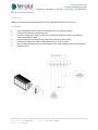
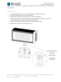
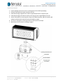
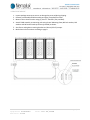
ZLM – User Manual and Installation Instructions
Overview:
Approvals:
ZLM modules and assemblies are suitable for general location usage both indoors and outdoors. Units
are approved for use through special electrical inspection to CSA SPE-1000 by an accredited inspection
agency (e.g. QPS, CSA). Each unit must be marked with the special inspection certification sticker.
Note: ZLM modules carry electrical approval for use in the following areas as defined by the
Canadian Electrical Code (CEC) and National Electrical Code (NEC):
• General Location
• Class I, Division 2, Groups ABCD
• Class I, Zone 2 Ex nA IIC, (T-code to be determined)
• Class I, Zone 2 AEx nA IIC, (T-code to be determined)
Product Application Space and Feature Set:
The ZLM and multi-unit ZLM assemblies are designed for use indoor or outdoor, in wet locations and
areas where the units will be subject to dirt and debris exposure, high vibration, corrosive environments,
and rough usage.
HOUSING: Main case components are made from hard anodized 6063-T5 aluminum alloy, with powdercoated cast-aluminum end-caps. Mounting hardware is made from hard anodized 6061-T6 aluminum.
Alloys and coatings designed for excellent corrosion resistance in harsh environments.
CABLE: Cable used in pre-wired units or assemblies is an SOOW cable rated as 90ºC 600 Volt CSA/UL
Portable Cord and suitable for extra hard usage.
FASTENERS: A2 and A4 stainless steel fasteners for high strength and excellent corrosion resistance.
Author: J.Levine
Approved: R.Hanson
Revision: A-01
Date: Jan 13, 2014
Date: Jan 13, 2014
P a g e |1 - 7
MOUNTING:
1. TRIPOD:
Single unit mounted on low tripod with ergonomic carrying handle
2. YOKE:
Single unit yoke-mount for pitch adjustment. Yoke can be direct mounted to any
flat surface with a single ¾” post or 4 x ⅜” bolts.
3. TENON/POLE:
Single unit yoke-mount for pitch adjustment. Yoke can be mounted to standard
2 ½” mounting pole.
4. 3 GANG:
Three unit assembly with mounting yoke. Single electrical connection per 3-unit
assembly. Individually adjustable pitch.
5. 4 GANG:
Four unit assembly with mounting yoke. Single electrical connection per 4-unit
assembly.
VOLTAGE: VAC: 120 to 277VAC
CURRENT (TYPICAL): 2.4A at 120VAC | 1.0A at 277VAC
CONNECTIONS: 1/2” Panel Knockout (21mm diameter) or Flying Lead;
Black: Line | White: Neutral | Green: Earth
OPERATING TEMPERATURE RANGE: -40°C to +50°C
INGRESS PROTECTION: IP56 – Fully sealed electronics and light engine cavities
Warnings:
Available Accessories:
DIMMING: Only available on single unit with flying lead.
SAFETY CABLE: Aircraft cable safety backup for elevated installations.
CONTACT FOR FURTHER AVAILABLE OPTIONS.
Author: J.Levine
Approved: R.Hanson
Revision: A-01
Date: Jan 13, 2014
Date: Jan 13, 2014
P a g e |2 - 7
Electrical Connections:
FLYING LEAD:
Wiring to be completed by qualified personnel as per applicable standards for area of use.
FIELD WIRED:
1.
2.
3.
4.
5.
6.
7.
Inspect package contents to ensure no damage has occurred during shipping.
Remove ZLM module or assembly from box.
Verify line voltage and frequency conform to product specifications (shown on specification
sheet and certification label.
Remove cast end plate using (10) ten x M4 socket head cap screws (shown).
Feed cable through strain relief or approved alternative. Torque to spec.
Wire according to diagram (shown) (terminations to be made using #6 insulated ring terminals).
Energize fixture.
Author: J.Levine
Approved: R.Hanson
Revision: A-01
Date: Jan 13, 2014
Date: Jan 13, 2014
P a g e |3 - 7
Installation:
SINGLE UNIT YOKE:
1.
2.
3.
4.
Inspect package contents to ensure no damage has occurred during shipping.
Remove ZLM module and yoke assembly from box.
Mount Yoke to install location using (4) four ⅜” bolts (not provided).
Attach ZLM module to mounting yoke using Central Mounting Plate, M6 lock washers, M6
washers and M6 socket head cap screws (provided) as shown.
5. Aim fixture and tighten mounting brackets to 6.8 N.m (60 in.lb) torque.
6. Make electrical connections according to page 3.
Author: J.Levine
Approved: R.Hanson
Revision: A-01
Date: Jan 13, 2014
Date: Jan 13, 2014
P a g e |4 - 7
TENON/POLE MOUNT:
1.
2.
3.
4.
5.
Inspect package contents to ensure no damage has occurred during shipping.
Remove ZLM module and yoke assembly from box.
Feed cable through supplied strain relief or approved alternative. Torque to spec.
Feed cable through pole. Mount yoke to pole using (3) three supplied M6 cap screws.
Attach ZLM module to mounting yoke using Central Mounting Plate, M6 lock washers, M6
washers and M6 socket head cap screws (provided) as shown.
6. Aim fixture and tighten mounting brackets to 6.8 N.m (60 in.lb) torque.
7. Make electrical connections according to page 3.
Author: J.Levine
Approved: R.Hanson
Revision: A-01
Date: Jan 13, 2014
Date: Jan 13, 2014
P a g e |5 - 7
3 GANG YOKE MOUNT:
Author: J.Levine
Approved: R.Hanson
Revision: A-01
Date: Jan 13, 2014
Date: Jan 13, 2014
P a g e |6 - 7
4 GANG YOKE MOUNT:
1.
2.
3.
4.
Inspect package contents to ensure no damage has occurred during shipping.
Remove pre-assembled ZLM4 assembly and yoke (if supplied) from box.
Mount Yoke to install location using (3) three ¾” fasteners (not provided).
Attach ZLM4 assembly to mounting yoke using Central Mounting Plate, M6 lock washers, M6
washers and M6 socket head cap screws (provided) as shown.
5. Aim fixture and tighten mounting brackets to 6.8 N.m (60 in.lb) torque.
6. Make electrical connections according to page 3.
Author: J.Levine
Approved: R.Hanson
Revision: A-01
Date: Jan 13, 2014
Date: Jan 13, 2014
P a g e |7 - 7