1
UM0324
User manual
STR750
AC induction motor IFOC software library V1.0
Introduction
This user manual describes the AC induction motor IFOC software library, an Indirect Field
Oriented Control (IFOC) Firmware Library for 3-phase induction motors developed for the
STR750 microcontroller.
This 32 bit, ARM cored ST microcontroller, comes with a set of peripherals which make it
suitable for performing both permanent magnet and AC induction motors FOC. In particular,
this manual describes the STR750 software library developed to control AC induction
motors equipped with an encoder or tacho-generator, in both open and closed loop. The
control of a permanent magnet (PM) motor in sinewave mode with encoder is described in
the UM0312 User Manual.
The AC IM IFOC software library is made of several C modules, compatible with the IAR
EWARM toolchain. It will allow you to quickly evaluate both the MCU and the available tools.
In addition, when used together with the STR750 motor control starter kit (STR750-MCKIT)
and an AC induction motor, you will be able to get a motor running in a very short time. It
also eliminates the need for time-consuming development of IFOC and speed regulation
algorithms by providing ready-to-use functions that let you concentrate on the application
layer.
A prerequisite for using this library is basic knowledge of C programming, AC motor drives
and power inverter hardware. In-depth know-how of STR750 functions is only required for
customizing existing modules and for adding new ones for a complete application
development.
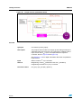
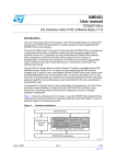
The figure below shows the architecture of the firmware. It uses the STR750 Standard
Library extensively but it also acts directly on hardware peripherals when optimizations in
terms of execution speed or code size are required.
February 2007
Rev 1
1/105
www.st.com
UM0324
AC IM IFOC software library V1.0 features (CPU running at
60MHz)
●
●
●
Speed feedback:
–
Tacho generator
–
Quadrature incremental encoder
Current sampling method:
–
2 isolated current sensors (ICS)
–
3-shunt resistors placed on the bottom of the three inverter legs
Current regulation for torque and flux control:
–
●
●
Note:
PIDs sampling frequency adjustable up to the PWM frequency.
Speed control:
–
Open loop operation
–
Closed loop operation, PID regulation with 0.5ms to 127ms sampling time
16-bit space vector PWM generation frequencies:
–
PWM frequency can be easily adjusted
–
Centered PWM pattern type
–
11 bits resolution at 14.6Khz
●
Free C source code and spreadsheet for look-up tables
●
CPU load below 30% (IFOC algorithm refresh frequency 8KHz)
●
Motor control modules developed in accordance with MISRA C rules
●
Code size 22.8KB (three shunt resistors for current reading, tacho generator for speed
feedback) + 8.2KB for LCD/joystick management
These figures are for information only; this software library may be subject to changes
depending on the final application and peripheral resources. Note that it was built using
robustness-oriented structures, thus preventing the speed or code size from being fully
optimized.
Related documents:
Available on www.st.com:
●
STR750 User Manual,
●
STR750 Datasheet,
●
STR750 Standard Library User Manual,
●
STR7 Flash Programming Manual
Available on www.arm.com:
ARM7TDMI-S Rev.4 Technical Reference Manual ARM DDI 0234A
2/105
UM0324
Contents
Contents
1
Getting started with tools . . . . . . . . . . . . . . . . . . . . . . . . . . . . . . . . . . . . 11
1.1
Working environment . . . . . . . . . . . . . . . . . . . . . . . . . . . . . . . . . . . . . . . . 11
1.2
Software tools . . . . . . . . . . . . . . . . . . . . . . . . . . . . . . . . . . . . . . . . . . . . . . 11
1.3
Library source code . . . . . . . . . . . . . . . . . . . . . . . . . . . . . . . . . . . . . . . . . 12
1.4
2
1.3.1
Download . . . . . . . . . . . . . . . . . . . . . . . . . . . . . . . . . . . . . . . . . . . . . . . . 12
1.3.2
File structure . . . . . . . . . . . . . . . . . . . . . . . . . . . . . . . . . . . . . . . . . . . . . 12
1.3.3
Starting the IAR toolchain . . . . . . . . . . . . . . . . . . . . . . . . . . . . . . . . . . . 13
Customizing the workspace for your STR750X derivative . . . . . . . . . . . . 13
1.4.1
Inkarm_xxx.xcl file (internal/external flash or RAM based project) 13
1.4.2
Extended linker file setting . . . . . . . . . . . . . . . . . . . . . . . . . . . . . . . . . . . 14
Getting started with the library . . . . . . . . . . . . . . . . . . . . . . . . . . . . . . . 16
2.1
Introduction to AC induction motor FOC drive . . . . . . . . . . . . . . . . . . . . . 16
2.2
How to customize hardware and software parameters . . . . . . . . . . . . . . 17
2.2.1
Library configuration file: 75x_MCconf.h . . . . . . . . . . . . . . . . . . . . . . . 18
2.2.2
Drive control parameters: MC_Control_Param.h . . . . . . . . . . . . . . . . 19
Power device control parameters . . . . . . . . . . . . . . . . . . . . . . . . . . . . . . . . . . . . .19
Flux and torque PID regulators sampling rate . . . . . . . . . . . . . . . . . . . . . . . . . . .19
Speed regulation loop frequency . . . . . . . . . . . . . . . . . . . . . . . . . . . . . . . . . . . . .19
Speed controller setpoint and PID constants (initial values) . . . . . . . . . . . . . . . .20
Torque and flux controller setpoints and PID constants . . . . . . . . . . . . . . . . . . . .20
Start-up torque ramp parameters . . . . . . . . . . . . . . . . . . . . . . . . . . . . . . . . . . . . .21
Linear variation of PID constants according to mechanical speed. . . . . . . . . . . .21
2.3
3
2.2.3
Incremental encoder parameters: MC_encoder_param.h . . . . . . . . . 21
2.2.4
Tachogenerator parameters: MC_tacho_prm.h . . . . . . . . . . . . . . . . . . 21
2.2.5
AC induction motor parameters: MC_ACmotor_param.h . . . . . . . . . . 23
How to define and add a c module . . . . . . . . . . . . . . . . . . . . . . . . . . . . . . 24
Running the demo program . . . . . . . . . . . . . . . . . . . . . . . . . . . . . . . . . . 26
3.1
Open loop . . . . . . . . . . . . . . . . . . . . . . . . . . . . . . . . . . . . . . . . . . . . . . . . . 27
3.2
Closed loop . . . . . . . . . . . . . . . . . . . . . . . . . . . . . . . . . . . . . . . . . . . . . . . 29
3.3
Setting up the system when using ICS sensors . . . . . . . . . . . . . . . . . . . . 30
3.3.1
Connecting the two ICS sensors to the motor and to STR750 . . . . . . . 31
3.3.2
Selecting PHASE_A_CHANNEL and PHASE_B_CHANNEL . . . . . . . . 31
3/105
Contents
4
UM0324
3.4
How to build the system when using an incremental encoder . . . . . . . . . 32
3.5
Fault messages . . . . . . . . . . . . . . . . . . . . . . . . . . . . . . . . . . . . . . . . . . . . 33
3.6
Note on debugging tools . . . . . . . . . . . . . . . . . . . . . . . . . . . . . . . . . . . . . 34
Library functions . . . . . . . . . . . . . . . . . . . . . . . . . . . . . . . . . . . . . . . . . . . 35
4.1
Function description conventions . . . . . . . . . . . . . . . . . . . . . . . . . . . . . . . 35
4.2
Current reading in three shunt resistor topology and space vector PWM
generation: 75x_svpwm_3shunt module . . . . . . . . . . . . . . . . . . . . . . . . 35
4.2.1
Overview . . . . . . . . . . . . . . . . . . . . . . . . . . . . . . . . . . . . . . . . . . . . . . . . 35
4.2.2
List of available functions . . . . . . . . . . . . . . . . . . . . . . . . . . . . . . . . . . . . 36
SVPWM_3ShuntInit . . . . . . . . . . . . . . . . . . . . . . . . . . . . . . . . . . . . . . . . . . . . . .36
SVPWM_3ShuntCurrentReadingCalibration . . . . . . . . . . . . . . . . . . . . . . .37
SVPWM_3ShuntGetPhaseCurrentValues . . . . . . . . . . . . . . . . . . . . . . . . . . .37
SVPWM_3ShuntCalcDutyCycles . . . . . . . . . . . . . . . . . . . . . . . . . . . . . . . . . . .38
SVPWM_3ShuntGPADCConfig . . . . . . . . . . . . . . . . . . . . . . . . . . . . . . . . . . . . . .38
4.2.3
Space vector PWM implementation . . . . . . . . . . . . . . . . . . . . . . . . . . . . 39
4.2.4
Current sampling in three shunt topology and general purpose A/D
conversions
4.2.5
41
Tuning delay parameters and sampling stator currents in three shunt
resistor topology . . . . . . . . . . . . . . . . . . . . . . . . . . . . . . . . . . . . . . . . . . . 43
Case 1: Duty cycle applied to Phase A low side switch is larger than
DT+TN+ 2TS + TH + TDMA . . . . . . . . . . . . . . . . . . . . . . . . . . . . . . . . . . . . . . . . .44
Case 2: DT+TN+TS < Phase A duty cycle < DT+TN+ 2TS + TH + TDMA. . . . . .46
Case 3: Phase A pulse width < DT+TN+TS . . . . . . . . . . . . . . . . . . . . . . . . . . . . .48
4.3
Isolated current sensor reading and space vector PWM generation:
75x_svpwm_ICS module . . . . . . . . . . . . . . . . . . . . . . . . . . . . . . . . . . . 52
4.3.1
Overview . . . . . . . . . . . . . . . . . . . . . . . . . . . . . . . . . . . . . . . . . . . . . . . . 52
4.3.2
List of available functions and interrupt service routines . . . . . . . . . . . . 52
SVPWM_IcsInit . . . . . . . . . . . . . . . . . . . . . . . . . . . . . . . . . . . . . . . . . . . . . . . . .53
SVPWM_IcsCurrentReadingCalibration . . . . . . . . . . . . . . . . . . . . . . . . . .53
SVPWM_IcsGetPhaseCurrentValues . . . . . . . . . . . . . . . . . . . . . . . . . . . . . .54
SVPWM_IcsCalcDutyCycles . . . . . . . . . . . . . . . . . . . . . . . . . . . . . . . . . . . . . .54
4.3.3
4.4
Current sampling in isolated current sensor topology and integrating
general purpose A/D conversions . . . . . . . . . . . . . . . . . . . . . . . . . . . . . 54
Induction motor IFOC vector control: MC_IFOC_Drive.c module . . . . . 55
4.4.1
Overview . . . . . . . . . . . . . . . . . . . . . . . . . . . . . . . . . . . . . . . . . . . . . . . . 55
4.4.2
List of available C functions . . . . . . . . . . . . . . . . . . . . . . . . . . . . . . . . . . 56
IFOC_Init . . . . . . . . . . . . . . . . . . . . . . . . 56
IFOC_Model . . . . . . . . . . . . . . . . . . . . . . . . . . . . . . . . . . . . . . . . . . . . . . . . . . . .57
IFOC_CalcFluxTorqueRef . . . . . . . . . . . . . . . . . . . . . . . . . . . . . . . . . . . . . . .59
4/105
UM0324
Contents
CalcIm. . . . . . . . . . . . . . . . . . . . . . . . . . . . . . . . . . . . . . . . . . . . . . . . . . . . . . . . .60
CalcRotFlxSlipFreq. . . . . . . . . . . . . . . . . . . . . . . . . . . . . . . . . . . . . . . . . . . .61
4.5
4.4.3
Detailed explanation about indirect field oriented control (IFOC) . . . . . 61
4.4.4
Detailed explanation about field weakening operation . . . . . . . . . . . . . . 63
Reference frame transformations: MC_Clarke_Park.h module . . . . . . 65
4.5.1
Overview . . . . . . . . . . . . . . . . . . . . . . . . . . . . . . . . . . . . . . . . . . . . . . . . 65
4.5.2
List of available C functions . . . . . . . . . . . . . . . . . . . . . . . . . . . . . . . . . . 66
Clarke. . . . . . . . . . . . . . . . . . . . . . . . . . . . . . . . . . . . . . . . . . . . . . . . . . . . . . . . .66
Park . . . . . . . . . . . . . . . . . . . . . . . . . . . . . . . . . . . . . . . . . . . . . . . . . . . . . . . . . . .67
Rev_Park . . . . . . . . . . . . . . . . . . . . . . . . . . . . . . . . . . . . . . . . . . . . . . . . . . . . . .67
Rev_Park_Circle_Limitation . . . . . . . . . . . . . . . . . . . . . . . . . . . . . . . . . . .68
4.6
4.5.3
Detailed explanation about reference frame transformations . . . . . . . . 68
4.5.4
Circle limitation . . . . . . . . . . . . . . . . . . . . . . . . . . . . . . . . . . . . . . . . . . . 70
Encoder feedback processing: 75x_encoder.c module . . . . . . . . . . . 72
4.6.1
List of available functions and interrupt service routines . . . . . . . . . . . . 72
ENC_Init . . . . . . . . . . . . . . . . . . . . . . . . . 72
ENC_GetPosition . . . . . . . . . . . . . . . . . . . . . 73
ENC_Get_Electrical_Angle . . . . . . . . . . . . . . . . . 73
ENC_Get_Mechanical_Angle . . . . . . . . . . . . . . . . . 73
ENC_ResetEncoder . . . . . . . . . . . . . . . . . . . . . 74
ENC_Clear_Speed_Buffer . . . . . . . . . . . . . . . . . . 74
ENC_Get_Speed . . . . . . . . . . . . . . . . . . . . . . 74
ENC_Get_Average_Speed . . . . . . . . . . . . . . . . . . 75
TIMx_UP_IRQHandler - interrupt routine . . . . . . . . . . . . . . . . . . . . . . . . . . . . .75
4.7
Tachogenerator feedback processing: 75x_tacho.c module . . . . . . . . 76
4.7.1
List of available functions and interrupt service routines . . . . . . . . . . . . 76
TAC_TachoTimerInit . . . . . . . . . . . . . . . . . . . . 76
TAC_InitTachoMeasure . . . . . . . . . . . . . . . . . . . 77
TAC_GetRotorFreqInHz . . . . . . . . . . . . . . . . . . . 77
TAC_GetRotorFreq . . . . . . . . . . . . . . . . . . . . . 78
GetLastTachoPeriod . . . . . . . . . . . . . . . . . . . . 78
GetAvrgTachoPeriod . . . . . . . . . . . . . . . . . . . . 78
TAC_IsTimedOut . . . . . . . . . . . . . . . . . . . . . . 79
TAC_ClrTimeOut . . . . . . . . . . . . . . . . . . . . . . 79
TAC_GetCaptCounter . . . . . . . . . . . . . . . . . . . . 79
TAC_ClrCaptCounter . . . . . . . . . . . . . . . . . . . . 80
TAC_StartTachoFiltering . . . . . . . . . . . . . . . . . 80
TAC_ValidSpeedInfo . . . . . . . . . . . . . . . . . . . . 80
TIMx_IC12_IRQHandler . . . . . . . . . . . . . . . . . . . 81
TIMx_UP_IRQHandler . . . . . . . . . . . . . . . . . . . . 81
5/105
Contents
UM0324
4.8
4.7.2
Integration tips . . . . . . . . . . . . . . . . . . . . . . . . . . . . . . . . . . . . . . . . . . . . 81
4.7.3
Operating principle . . . . . . . . . . . . . . . . . . . . . . . . . . . . . . . . . . . . . . . . . 81
4.7.4
Converting Hertz into pseudo frequency . . . . . . . . . . . . . . . . . . . . . . . . 83
Flux, torque and speed regulators: MC_PID_regulators module . . . . 83
4.8.1
Overview . . . . . . . . . . . . . . . . . . . . . . . . . . . . . . . . . . . . . . . . . . . . . . . . 83
4.8.2
List of available functions and interrupt service routines . . . . . . . . . . . . 83
PID_Init . . . . . . . . . . . . . . . . . . . . . . . . . 83
PID_Flux_Regulator . . . . . . . . . . . . . . . . . . . . 84
PID_Torque_Regulator . . . . . . . . . . . . . . . . . . . 84
PID_Speed_Regulator . . . . . . . . . . . . . . . . . . . 85
PID_Reset_Integral_terms . . . . . . . . . . . . . . . . . 85
PID_Speed_Coefficients_update . . . . . . . . . . . . . . 85
PID_Integral_Speed_update . . . . . . . . . . . . . . . . 85
4.8.3
PID regulator theoretical background . . . . . . . . . . . . . . . . . . . . . . . . . . 86
4.8.4
Regulator sampling time setting . . . . . . . . . . . . . . . . . . . . . . . . . . . . . . 86
4.8.5
Adjusting speed regulation loop Ki, Kp and Kd vs motor frequency . . . 87
Disabling the linear curve computation routine, 75x_it.c module. . . . . . . . . . .88
4.9
Main interrupt service routines: 75x_it module . . . . . . . . . . . . . . . . . . 89
4.9.1
Overview . . . . . . . . . . . . . . . . . . . . . . . . . . . . . . . . . . . . . . . . . . . . . . . . 89
4.9.2
List of non-empty interrupt service routines . . . . . . . . . . . . . . . . . . . . . . 89
PWM_EM_IRQHandler . . . . . . . . . . . . . . . . . . . . . . . . . . . . . . . . . . . . . . . . . . . . .89
ADC_IRQHandler . . . . . . . . . . . . . . . . . . . . . . . . . . . . . . . . . . . . . . . . . . . . . . . .90
4.10
General purpose time base: 75x_TBtimer module . . . . . . . . . . . . . . . . 90
4.10.1
Overview . . . . . . . . . . . . . . . . . . . . . . . . . . . . . . . . . . . . . . . . . . . . . . . . 90
4.10.2
List of available functions and interrupt service routines . . . . . . . . . . . . 90
TB_StartUpInit . . . . . . . . . . . . . . . . . . . . . . 91
TB_Timebase_Timer_Init . . . . . . . . . . . . . . . . . . . . . . . . . . . . . . . . . . . . . . .91
TB_Wait. . . . . . . . . . . . . . . . . . . . . . . . . . . . . . . . . . . . . . . . . . . . . . . . . . . . . . . .92
TB_Set_Delay_500us, TB_Set_DisplayDelay_500us,
TB_Set_StartUp_Timeout . . . . . . . . . . . . . . . . . . . . . . . . . . . . . . . . . . . . . . .92
TB_StartUp_Timeout_IsElapsed, TB_Delay_IsElapsed,
TB_DisplayDelay_IsElapsed . . . . . . . . . . . . . . . . . . . . . . . . . . . . . . . . . . . .92
TB_IRQHandler . . . . . . . . . . . . . . . . . . . . . . . . . . . . . . . . . . . . . . . . . . . . . . . . .93
4.11
5
Application layer . . . . . . . . . . . . . . . . . . . . . . . . . . . . . . . . . . . . . . . . . . . 93
MISRA compliance . . . . . . . . . . . . . . . . . . . . . . . . . . . . . . . . . . . . . . . . . 94
5.1
Analysis method . . . . . . . . . . . . . . . . . . . . . . . . . . . . . . . . . . . . . . . . . . . . 94
5.2
Limitations . . . . . . . . . . . . . . . . . . . . . . . . . . . . . . . . . . . . . . . . . . . . . . . . 94
5.2.1
6/105
MISRA compliance for AC IM library files . . . . . . . . . . . . . . . . . . . . . . . 94
UM0324
Contents
5.2.2
MISRA rule deviations . . . . . . . . . . . . . . . . . . . . . . . . . . . . . . . . . . . . . . 96
Appendix A Additional information. . . . . . . . . . . . . . . . . . . . . . . . . . . . . . . . . . . . 97
6
A.1
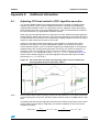
Adjusting CPU load related to IFOC algorithm execution . . . . . . . . . . . . . 97
A.2
Selecting PWM frequency for 3 shunt resistor configuration. . . . . . . . . . . 98
A.3
Fixed-point numerical representation . . . . . . . . . . . . . . . . . . . . . . . . . . . . 99
A.4
Tacho-based speed measurement flow charts . . . . . . . . . . . . . . . . . . . . 100
A.5
PID block diagrams . . . . . . . . . . . . . . . . . . . . . . . . . . . . . . . . . . . . . . . . . 102
A.6
Additional or up-to-date technical literature. . . . . . . . . . . . . . . . . . . . . . . 103
A.7
References . . . . . . . . . . . . . . . . . . . . . . . . . . . . . . . . . . . . . . . . . . . . . . . 103
Revision history . . . . . . . . . . . . . . . . . . . . . . . . . . . . . . . . . . . . . . . . . . 104
7/105
List of tables
UM0324
List of tables
Table 1.
Table 2.
Table 3.
Table 4.
8/105
Sector identification . . . . . . . . . . . . . . . . . . . . . . . . . . . . . . . . . . . . . . . . . . . . . . . . . . . . . . 40
PWM frequency vs maximum duty cycle relationship. . . . . . . . . . . . . . . . . . . . . . . . . . . . . 51
MISRA compliance of AC IM library files . . . . . . . . . . . . . . . . . . . . . . . . . . . . . . . . . . . . . . 94
System performance when using STR750-MCKIT . . . . . . . . . . . . . . . . . . . . . . . . . . . . . . . 99
UM0324
List of figures
List of figures
Figure 1.
Figure 2.
Figure 3.
Figure 4.
Figure 5.
Figure 6.
Figure 7.
Figure 8.
Figure 9.
Figure 10.
Figure 11.
Figure 12.
Figure 13.
Figure 14.
Figure 15.
Figure 16.
Figure 17.
Figure 18.
Figure 19.
Figure 20.
Figure 21.
Figure 22.
Figure 23.
Figure 24.
Figure 25.
Figure 26.
Figure 27.
Figure 28.
Figure 29.
Figure 30.
Figure 31.
Figure 32.
Figure 33.
Figure 34.
Figure 35.
Figure 36.
Figure 37.
Figure 38.
Figure 39.
Figure 40.
JTAG interface for debugging and programming . . . . . . . . . . . . . . . . . . . . . . . . . . . . . . . . 11
File structure . . . . . . . . . . . . . . . . . . . . . . . . . . . . . . . . . . . . . . . . . . . . . . . . . . . . . . . . . . . . 12
Device summary . . . . . . . . . . . . . . . . . . . . . . . . . . . . . . . . . . . . . . . . . . . . . . . . . . . . . . . . . 13
Extended linker file Inkarm_flash.xcl, flash memory length definition . . . . . . . . . . . . 14
Extended linker file setting . . . . . . . . . . . . . . . . . . . . . . . . . . . . . . . . . . . . . . . . . . . . . . . . . 15
FOC drive placed in a speed loop . . . . . . . . . . . . . . . . . . . . . . . . . . . . . . . . . . . . . . . . . . . 16
FOC structure . . . . . . . . . . . . . . . . . . . . . . . . . . . . . . . . . . . . . . . . . . . . . . . . . . . . . . . . . . . 17
Torque vs. speed characteristic curve . . . . . . . . . . . . . . . . . . . . . . . . . . . . . . . . . . . . . . . . 24
Adding a new module . . . . . . . . . . . . . . . . . . . . . . . . . . . . . . . . . . . . . . . . . . . . . . . . . . . . . 25
Key function assignments . . . . . . . . . . . . . . . . . . . . . . . . . . . . . . . . . . . . . . . . . . . . . . . . . . 26
Main.c state machine . . . . . . . . . . . . . . . . . . . . . . . . . . . . . . . . . . . . . . . . . . . . . . . . . . . . 27
LCD menus in open loop . . . . . . . . . . . . . . . . . . . . . . . . . . . . . . . . . . . . . . . . . . . . . . . . . . 27
Open loop start-up strategy . . . . . . . . . . . . . . . . . . . . . . . . . . . . . . . . . . . . . . . . . . . . . . . . 28
LCD menus in closed loop . . . . . . . . . . . . . . . . . . . . . . . . . . . . . . . . . . . . . . . . . . . . . . . . . 29
Closed loop start-up strategy . . . . . . . . . . . . . . . . . . . . . . . . . . . . . . . . . . . . . . . . . . . . . . . 30
ICS hardware connections . . . . . . . . . . . . . . . . . . . . . . . . . . . . . . . . . . . . . . . . . . . . . . . . . 31
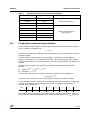
Encoder output signals: counter operation . . . . . . . . . . . . . . . . . . . . . . . . . . . . . . . . . . . . . 32
DBGC bit in PWM control register (extract from STR750 reference manual). . . . . . . . . . . 34
Valfa and Vbeta stator voltage components . . . . . . . . . . . . . . . . . . . . . . . . . . . . . . . . . . . . . 39
SVPWM phase voltages waveforms. . . . . . . . . . . . . . . . . . . . . . . . . . . . . . . . . . . . . . . . . . 39
PWM and TIM0 synchronization (REP_RATE=1) . . . . . . . . . . . . . . . . . . . . . . . . . . . . . . . . 42
Three shunt topology current sampling and GP A/D conversions integration
(REP_RATE=1) . . . . . . . . . . . . . . . . . . . . . . . . . . . . . . . . . . . . . . . . . . . . . . . . . . . . . . . . . . 43
Inverter leg and shunt resistor position . . . . . . . . . . . . . . . . . . . . . . . . . . . . . . . . . . . . . . . . 43
Low side switches gate signals (low modulation indexes) . . . . . . . . . . . . . . . . . . . . . . . . . 45
Low side Phase A duty cycle > DT+TN+ 2TS + TH + TDMA . . . . . . . . . . . . . . . . . . . . . . . 45
DT+TN+TS< Low side Phase A duty cycle < DT+TN+2TS+TH+TDMA and
ΔDutyA-B<DT+TN+TS . . . . . . . . . . . . . . . . . . . . . . . . . . . . . . . . . . . . . . . . . . . . . . . . . . . . 46
DT+TN+TS < Low side Phase A duty cycle < DT+TN+2TS+TH+TDMA and
ΔDutyA-B<DT+TN+TS . . . . . . . . . . . . . . . . . . . . . . . . . . . . . . . . . . . . . . . . . . . . . . . . . . . . 47
DT+TN+TS < Low side Phase A duty cycle < DT+TN+2TS+TH+TDMA and
ΔDutyA-B>DT+TN+TS . . . . . . . . . . . . . . . . . . . . . . . . . . . . . . . . . . . . . . . . . . . . . . . . . . . . 47
DT+TN+TS < Low side Phase A duty cycle < DT+TN+2TS+TH+TDMA and
ΔDutyA-B>DT+TN+TS . . . . . . . . . . . . . . . . . . . . . . . . . . . . . . . . . . . . . . . . . . . . . . . . . . . . 48
Low side duty cycle Phase A < DT+TN+TS and
ΔDutyA-B > DT+TN+2TS+TH+TDMA. . . . . . . . . . . . . . . . . . . . . . . . . . . . . . . . . . . . . . . . . 48
Low side duty cycle Phase A < DT+TN+TS and ΔDutyA-B > DT+TN+2TS+TH+TDMA . . 49
Low side duty cycle Phase A < DT+TN+TS and
DT+TRise+TS < ΔDutyA-B < DT+TN+2TS+TH+TDMA . . . . . . . . . . . . . . . . . . . . . . . . . . . 49
Low side duty cycle Phase A < DT+TN+TS and
DT+TRise+TS < ΔDutyA-B < DT+TN+2TS+TH+TDMA . . . . . . . . . . . . . . . . . . . . . . . . . . . 50
Low side duty cycle Phase A < DT+TN+TS and ΔDutyA-B< DT+TRise+TS . . . . . . . . . . 51
Stator currents sampling and GP conversions in ICS configuration (REP_RATE=1) . . . . . 55
Rotor flux angle calculation (quadrature encoder) . . . . . . . . . . . . . . . . . . . . . . . . . . . . . . . 58
Rotor flux angle calculation (tachogenerator) . . . . . . . . . . . . . . . . . . . . . . . . . . . . . . . . . . . 59
Torque and flux optimization block . . . . . . . . . . . . . . . . . . . . . . . . . . . . . . . . . . . . . . . . . . . 60
Torque vs. speed characteristic curve . . . . . . . . . . . . . . . . . . . . . . . . . . . . . . . . . . . . . . . . 64
Clarke, Park, and reverse Park transformations . . . . . . . . . . . . . . . . . . . . . . . . . . . . . . . . . 66
9/105
List of figures
Figure 41.
Figure 42.
Figure 43.
Figure 44.
Figure 45.
Figure 46.
Figure 47.
Figure 48.
Figure 49.
Figure 50.
Figure 51.
Figure 52.
Figure 53.
Figure 54.
10/105
UM0324
Transformation from an abc stationary frame to a qd rotating frame . . . . . . . . . . . . . . . . . 69
Circle limitation working principle . . . . . . . . . . . . . . . . . . . . . . . . . . . . . . . . . . . . . . . . . . . . 71
Automatic tacho timer prescaler decrease . . . . . . . . . . . . . . . . . . . . . . . . . . . . . . . . . . . . . 82
Automatic tacho timer prescaler increase. . . . . . . . . . . . . . . . . . . . . . . . . . . . . . . . . . . . . . 82
PID general equation . . . . . . . . . . . . . . . . . . . . . . . . . . . . . . . . . . . . . . . . . . . . . . . . . . . . . 86
Time domain to discrete PID equations . . . . . . . . . . . . . . . . . . . . . . . . . . . . . . . . . . . . . . . 87
Linear curve for coefficient computation . . . . . . . . . . . . . . . . . . . . . . . . . . . . . . . . . . . . . . . 88
AD conversions for three shunt topology stator currents reading and IFOC algorithm
execution when REP_RATE=3 . . . . . . . . . . . . . . . . . . . . . . . . . . . . . . . . . . . . . . . . . . . . . . 97
AD conversions for three shunt topology stator currents reading and IFOC algorithm
execution when REP_RATE=1 . . . . . . . . . . . . . . . . . . . . . . . . . . . . . . . . . . . . . . . . . . . . . . 98
Tacho capture overview . . . . . . . . . . . . . . . . . . . . . . . . . . . . . . . . . . . . . . . . . . . . . . . . . . 100
Processing captured value when timer did not overflow. . . . . . . . . . . . . . . . . . . . . . . . . . 101
Processing captured value when timer did overflow. . . . . . . . . . . . . . . . . . . . . . . . . . . . . 101
Torque/flux control loop block diagram . . . . . . . . . . . . . . . . . . . . . . . . . . . . . . . . . . . . . . . 102
Speed control loop block diagram . . . . . . . . . . . . . . . . . . . . . . . . . . . . . . . . . . . . . . . . . . 103
UM0324
1
Getting started with tools
Getting started with tools
To develop an application for an AC induction motor using the AC IM IFOC software library,
you must set up a complete development environment, as described in the following
sections. A PC running Windows XP is necessary.
1.1
Working environment
The AC IM IFOC software library was fully validated using the main hardware boards
included in STR750-MCKIT starter kit (a complete inverter and control board). The STR750MCKIT starter kit provides an ideal toolset for starting a project and using the library.
Therefore, for rapid implementation and evaluation of the software described in this user
manual, it is recommended to acquire this starter kit.
It is also recommended to install the IAR EWARM C toolchain which was used to compile
the AC IM IFOC software library. With this toolchain, you do not need to configure your
workspace. You can set up your workspace manually for any other toolchain. A free
‘kickstart edition’ of the IAR EWARM C toolchain with a 32Kb limitation can be downloaded
from www.iar.com; it is sufficient to compile and evaluate the software library presented
here.
1.2
Software tools
A complete software package consists of:
●
A third-party integrated development environment (IDE)
●
A third-party C-compiler
This library was compiled using the third-pary IAR C toolchain.
●
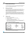
JTAG interface for debugging and programming
Using the JTAG interface of the MCU you can enter in-circuit debugging session with
most of toolchains. Each toolchain can be provided with an interface connected
between the PC and the target application.
Figure 1.
JTAG interface for debugging and programming
The JTAG interface can also be used for in-circuit programming of the MCU. Other
production programmers can be obtained from third-parties.
11/105
Getting started with tools
1.3
Library source code
1.3.1
Download
UM0324
The complete source files are available for free download on the ST website
(www.stmcu.com), in the Technical Literature and Support Files section, as a zip file.
Note:
It is highly recommended to check for the latest releases of the library before starting any
new development, and thento verify from time to time all release notes to be aware of any
new features that might be of interest for your project. Registration mechanisms are
available on ST web sites to automatically obtain updates.
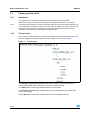
1.3.2
File structure
The AC IM IFOC software library contains the workspace for the IAR toolchain. Once the
files are unzipped, the following library structure appears, as shown in Figure 2.
Figure 2.
File structure
The STR750 FOC Firmware Libraries v1.0 folder contains the firmware libraries for
running both PMSM and AC induction three-phase sensored motors.
The StdLib folder contains the standard library for the STR750.
The Include and Source folder contain respectively the header and source files of the
motor control library.
Finally, IAR folder contains the configuration files for the EWARM toolchain.
12/105
UM0324
1.3.3
Getting started with tools
Starting the IAR toolchain
When you have installed the toolchain, you can open the workspace directly from the
dedicated folder, by double-clicking on the IFOC.eww file:
The file location is:
\ FOC_AC_SR_v1.0 \ IAR \ IFOC.eww
1.4
Customizing the workspace for your STR750X derivative
The AC IM IFOC software library was written for the STR750FVT2. However, it works
equally successfully with all the products in the STR75x family.
Using a different STR750 sales type may require some modifications to the library,
according to the available features (some of the I/O ports are not present on low-pin count
packages). Refer to the datasheet for further details.
Also, depending on the memory size, the workspace may have to be configured to fit your
STR75x MCU derivative.
Figure 3.
1.4.1
Device summary
Inkarm_xxx.xcl file (internal/external flash or RAM based project)
The IAR\config folder contains 3 files:
●
Inkarm_flash.xcl
●
Inkarm_smi.xcl
●
Inkarm_ram.xcl
These files are used as an extended command linker file and contain linker options. Memory
areas, start address, size, and other parameters are declared here. It also contains the
value assigned to the stack size for each ARM operating mode (for example, USER or FIQ.
Refer to the ARM7TDMI-S Technical Reference Manual for more information).
13/105
Getting started with tools
UM0324
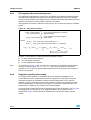
The default extended linker file used in the standard library to configure the device for
internal flash based resident firmware is Inkarm_flash.xcl. an extract of this file
showing the definitions of heap and stack size is provided below. Depending on the project
requirements, it may be necessary to manually edit the segment sizes.
//************************************************************************
*
// Stack and heap segments.
//************************************************************************
// Add size >0 for ABT_Stack, UND_Stack if you need them.
// size must be 8 byte aligned.
-D_CSTACK_SIZE=0x200
-D_SVC_STACK_SIZE=0x20
-D_IRQ_STACK_SIZE=0x100
-D_FIQ_STACK_SIZE=0x40
-D_ABT_STACK_SIZE=0x0
-D_UND_STACK_SIZE=0x0
-D_HEAP_SIZE=0x400
Memory size modifications might also be necessary according to the MCU specifications.
Default settings are done for a 256KB embedded flash memory. If you use a different device,
you must edit the Inkarm_flash.xcl file as explained in Section 1.4.2.
Figure 4.
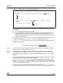
1.4.2
Extended linker file Inkarm_flash.xcl, flash memory length definition
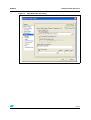
Extended linker file setting
As mentioned in the previous section, in the provided IAR workspace, the internal flash
extended linker file is set by default (Inkarm_flash.xcl).
To modify the linker file to be used (for example, Inkarm_ram.xcl or Inkarm_smi.xcl):
1.
Open the IAR workspace by double-clicking on the \ FOC_AC_SR_v1.0 \ IAR \
IFOC.eww file.
2.
Go to the Project menu, select Options... then Linker, and select the Config submenu.
The dialog box shown in Figure 5 is displayed.
3.
In the Override default field, type the name of the linker file you want to use, and then
click OK.
Selecting the Inkarm_ram.xcl file makes the IAR XLINK linker place the memory
segments on RAM memory, whereas selecting the Inkarm_smi.xcl file makes the
linker place the memory segments on an external memory.
14/105
UM0324
Getting started with tools
Figure 5.
Extended linker file setting
15/105
Getting started with the library
2
Getting started with the library
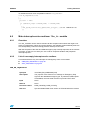
2.1
Introduction to AC induction motor FOC drive
UM0324
The AC IM IFOC software library is designed to achieve the high dynamic performance in
AC motor control offered by the field oriented control (FOC) strategy.
Through complex machine electrical quantity transformations, this well-established drive
system optimizes the control of the motor, to the extent that it is able to offer decoupled
torque (Te) and magnetic flux (λ) regulation. That is, it offers the same optimum and
favorable conditions as DC motors but, in this case, carried out with rugged and powerful AC
induction motors.
With this approach, it can be stated that the two currents iqsλr and idsλr, derived from stator
currents, have in AC Induction Motor (IM) the same role that armature and field currents
have in DC motors: the first is proportional to mechanical torque the second to the rotor flux.
In more detail, in the context of FOC, rotor flux position is indirectly calculated, starting from
transformed equations of the machine, by means of known motor parameters and stator
current measurements: this is why the controller is an indirect controller and, hence the
phrase IFOC drive.
In other words, it can be stated that IFOC drive is halfway between dynamic controllers
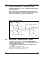
(speed, position …) and machine core. So, the system may well be depicted as in Figure 6,
if introduced in a loop for speed control.
Figure 6.
FOC drive placed in a speed loop
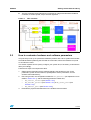
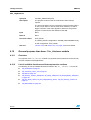
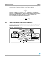
Basic information on field oriented structure and library functions is represented in Figure 7.
16/105
●
The θλr calculation block estimates rotor flux angle, which is essential to transformation
blocks (Park, Reverse Park) for performing field orientation, so that the currents
supplied to the machine can be oriented in phase and in quadrature to the rotor flux
vector. More in depth information about reference frame theory and FOC structure is
available in [1][2] and Section 4.4.3 on page 61.
●
The space vector PWM block (SVPWM) implements an advanced modulation method
that reduces current harmonics, thus optimizing DC bus exploitation.
●
The current reading block allows the system to measure stator currents correctly, using
either cheap shunt resistors or market-available isolated current Hall sensors (ICS).
●
The speed-reading block handles tachogenerator or incremental encoder signals in
order to acquire properly rotor angular velocity or position.
UM0324
Getting started with the library
●
The PID-controller block implements a proportional, integral and derivative feedback
controller, to achieve speed, torque and flux regulation.
Figure 7.
2.2
FOC structure
How to customize hardware and software parameters
It is quite easy to set up an operational evaluation platform with a drive system that includes
the STR750-MCKIT (featuring the STR750 microcontroller, where this software runs) and
an AC induction motor.
This section explains how to quickly configure your system and, if necessary, customize the
library accordingly.
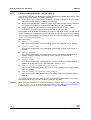
Follow these steps to accomplish this task:
1.
Gather all the information that is needed regarding the hardware in use (motor
parameters, power devices features, speed/position sensor parameters, current
sensors transconductance);
2.
Edit, using an IDE, the configuration header file 75x_MCconf.h (as explained in more
detail in Section 2.2.1), and the following parameter header files,
3.
–
MC_Control_Param.h (see Section 2.2.2),
–
MC_encoder_param.h (see Section 2.2.3) or MC_tacho_prm.h (see
Section 2.2.4),
–
MC_ACmotor_prm.h (see Section 2.2.5);
Re-build the project and download it on the STR750 microcontroller.
17/105
Getting started with the library
2.2.1
UM0324
Library configuration file: 75x_MCconf.h
The purpose of this file is to declare the compiler conditional compilation keys that are used
throughout the entire library compilation process to:
●
Select which current measurement technique is actually in use (the choice is between
three shunt or ICS sensors, according to availability).
●
Select which speed/position sensor is actually performed (here the choice is between
tachometer and quadrature incremental encoder, according to availability).
●
Enable or disable the derivative action in the speed controller or in the current
controllers in accordance with expected performance and code size.
If this header file is not edited appropriately (no choice or undefined choice), you will receive
an error message when building the project. Note that you will not receive an error message
if the configuration described in this header file does not match the hardware that is actually
in use, or in case of wrong wiring.
More specifically:
●
#define ICS_SENSORS
To be uncommented when current sampling is done using isolated current sensors.
●
#define THREE_SHUNT
To be uncommented when current sampling is performed via three shunt resistors
(default).
●
#define ENCODER
To be uncommented when an incremental encoder is connected to the starter kit for
position sensing; in parallel, fill out MC_encoder_param.h (as explained in
Section 2.2.3);.
●
#define TACHO
To be uncommented when a tachogenerator is in use to detect rotor speed (default); in
parallel, fill out MC_tacho_prm.h (as explained in Section 2.2.4);.
●
#define Id_Iq_DIFFERENTIAL_TERM_ENABLED
To be uncommented when differential terms for torque and flux control loop regulation
(PID) are enabled;
●
#define SPEED_DIFFERENTIAL_TERM_ENABLED
To be uncommented when differential term for speed control loop regulation (PID) is
enabled.
Once these settings have been done, only the required blocks will be linked in the project;
this means that you do not need to exclude .c files from the build.
Caution:
18/105
When using shunt resistors for current measurement, ensure that the REP_RATE parameter
(in MC_Control_Param.h) is set properly (see Section 2.2.2 and Section A.2: Selecting
PWM frequency for 3 shunt resistor configuration on page 98 for details).
UM0324
2.2.2
Getting started with the library
Drive control parameters: MC_Control_Param.h
The MC_Control_Param.h header file gathers parameters related to:
●
Power device control parameters on page 19
●
Flux and torque PID regulators sampling rate on page 19
●
Speed regulation loop frequency on page 19
●
Speed controller setpoint and PID constants (initial values) on page 20
●
Torque and flux controller setpoints and PID constants on page 20
●
Start-up torque ramp parameters on page 21
●
Linear variation of PID constants according to mechanical speed. on page 21
Power device control parameters
●
#define PWM_FREQ
Define here, in Hz, the switching frequency; in parallel, uncomment the maximum
allowed modulation index definition (MAX_MODULATION_XX_PER_CENT)
corresponding to the PWM frequency selection.
●
#define DEADTIME_NS
Define here, in ns, the dead time, in order to avoid shoot-through conditions.
Flux and torque PID regulators sampling rate
●
#define REP_RATE
Stator currents sampling frequency and consequently flux and torque PID regulators
sampling rate, are defined according to the following equation:
Flux and torque PIDs sampling rate =
2 ⋅ PWM _ FREQ
REP _ RATE + 1
In fact, because there is no reason for either executing the IFOC algorithm without updating
the stator currents values or for performing stator current conversions without running the
IFOC algorithm, in the proposed implementation the stator current sampling frequency and
the IFOC algorithm execution rate coincide.
Note:
REP_RATE must be an odd number if currents are measured by shunt resistors (see
Section A.2: Selecting PWM frequency for 3 shunt resistor configuration on page 98 for
details); its value is 8-bit long;
Speed regulation loop frequency
#define PID_SPEED_SAMPLING_TIME
The speed regulation loop frequency is selected by assigning one of the defines below:
#define
#define
#define
#define
#define
#define
PID_SPEED_SAMPLING_500us
PID_SPEED_SAMPLING_1ms
PID_SPEED_SAMPLING_2ms
PID_SPEED_SAMPLING_4.5ms
PID_SPEED_SAMPLING_10ms
PID_SPEED_SAMPLING_127ms
0
//min 500us
1
3
//(4-1)*500uS=2ms
6
15
255 //max(255-1)*500us=127ms
19/105
Getting started with the library
UM0324
Speed controller setpoint and PID constants (initial values)
●
#define PID_SPEED_REFERENCE
Define here, in 0.1Hz, the mechanical rotor speed setpoint at startup in closed loop
mode;
●
#define PID_SPEED_KP_DEFAULT
The proportional constant of the speed loop regulation (signed 16-bit value, adjustable
from 0 to 32767);
●
#define PID_SPEED_KI_DEFAULT
The integral constant of the speed loop regulation (signed 16-bit value, adjustable from
0 to 32767);
●
#define PID_SPEED_KD_DEFAULT
The derivative constant of the speed loop regulation (signed 16-bit value, adjustable
from 0 to 32767);
Torque and flux controller setpoints and PID constants
●
#define PID_TORQUE_REFERENCE
The torque reference value, in open loop, at start-up (signed 16-bit value);
●
#define PID_TORQUE_KP_DEFAULT
The proportional constant of the torque loop regulation (signed 16-bit value, adjustable
from 0 to 32767);
●
#define PID_TORQUE_KI_DEFAULT
The integral constant of the torque loop regulation (signed 16-bit value, adjustable from
0 to 32767);
●
#define PID_TORQUE_KD_DEFAULT
The derivative constant of the torque loop regulation (signed 16-bit value, adjustable
from 0 to 32767);
●
#define PID_FLUX_REFERENCE
The flux reference; its default value is NOMINAL_FLUX, which is adjustable by
modifying the parameter hNominal_Flux (see Section 2.2.5);
●
#define PID_FLUX_KP_DEFAULT
The proportional constant of the flux loop regulation (signed 16-bit value, adjustable
from 0 to 32767);
●
#define PID_FLUX_KI_DEFAULT
The integral constant of the flux loop regulation (signed 16-bit value, adjustable from 0
to 32767);
●
#define PID_FLUX_KD_DEFAULT
The derivative constant of the flux loop regulation (signed 16-bit value, adjustable from
0 to 32767);
20/105
UM0324
Getting started with the library
Start-up torque ramp parameters
See Section 3.1: Open loop and Section 3.2: Closed loop on page 29 for details.
●
#define STARTUP_TIMEOUT
Define here, in ms, the overall time allowed for start-up;
●
#define STARTUP_RAMP_DURATION
Define here, in ms, the duration of the torque ramp up;
●
#define STARTUP_FINAL_TORQUE
Define here, in q1.15 format, the final reference value for torque ramp up (closed loop
only);
●
#define TACHO_SPEED_VAL
Define here, in 0.1Hz, the lowest speed for tachogenerator reading validation.
Linear variation of PID constants according to mechanical speed.
Refer to Section 4.8.5: Adjusting speed regulation loop Ki, Kp and Kd vs motor frequency on
page 87.
2.2.3
Incremental encoder parameters: MC_encoder_param.h
The MC_encoder_parameter.h header file is to be filled out if position/speed sensing is
performed by means of a quadrature, square wave, relative rotary encoder.
●
#define ENCODER_PPR
Define here the number of pulses, generated by a single channel, for one shaft
revolution (actual resolution will be 4x);
●
#define TIMER0_HANDLES_ENCODER
To be uncommented if the two sensor output signals are wired to TIMER0 input pins;
●
#define TIMER1_HANDLES_ENCODER
to be uncommented if the two sensor output signals are wired to TIMER1 input pins;
●
#define TIMER2_HANDLES_ENCODER
To be uncommented if the two sensor output signals are wired to TIMER2 input pins
(default; required if using STR750-MCKIT).
2.2.4
Tachogenerator parameters: MC_tacho_prm.h
The MC_tacho_prm.h header file is to be filled out if speed sensing is performed using an
AC tachogenerator. Extra details and more explanations on tacho-based speed
measurement can be found in Section 4.7 on page 76 and Section A.4 on page 100.
●
#define TACHO_PULSE_PER_REV
Define here the number of pulses per revolution given by the tachogenerator; in order
to verify the correct operation of the tacho module, this parameter can be set to 1, so
that the frequency measurement can be directly compared with the one of a signal
generator.
21/105
Getting started with the library
●
UM0324
#define TIMER0_HANDLES_TACHO
To be uncommented if tachogenerator-based speed measurement is performed by
TIMER0.
●
#define TIMER1_HANDLES_TACHO
To be uncommented if tachogenerator-based speed measurement is performed by
TIMER1.
●
#define TIMER2_HANDLES_TACHO
To be uncommented if tachogenerator-based speed measurement is performed by
TIMER2. (Default; required if using STR750-MCKIT, in conjunction with Input Capture 1
choice - see below).
●
#define TACHO_INPUT_TI1
To be uncommented if sensor output signal is wired to TimerX Input Capture 1. (Default
- in conjunction with TIMER2 choice; required if using STR750-MCKIT).
●
#define TACHO_INPUT_TI2
To be uncommented if sensor output signal is wired to TimerX Input Capture 2.
●
#define MAX_SPEED_FDBK
This parameter defines the frequency above which speed feedback is not realistic in
the application: this allows to discriminate glitches for example. The unit is 0.1Hz. By
default, it is set to 6400 (640.0Hz), which corresponds to approximately 20000 RPM for
a two pole pair motor.
●
#define MAX_SPEED
This parameter is the value returned by the function TAC_GetRotorFreqInHz if
measured speed is greater than MAX_SPEED_FDBK. The default value is 640Hz, but
it can be 0 or FFFF depending on how this value is managed by the upper layer
software.
●
#define MAX_PSEUDO_SPEED
This parameter is the value returned by the function TAC_GetRotorFreq if measured
speed is greater than MAX_SPEED_FDBK. The unit is rad/pwm period
(2π rad = 0xFFFF). See Section 4.7.4: Converting Hertz into pseudo frequency on
page 83 for more details.
●
#define MIN_SPEED_FDBK
This parameter is the frequency below which speed feedback is not realistic in the
application: this allows to discriminate too low frequency. This value is set to 1 Hz by
default, and depends on sensor and signal conditioning stage characteristics. Typically,
the tacho signal is too weak at very low speed to trigger input capture on the MCU.
Note:
The MC_tacho_prm.h file includes two formulas that allow to compute the minimum sensed
speed when speed is increasing (during start-up) or decreasing (during motor stop).
●
#define MAX_RATIO
Maximum possible TIMER clock prescaler ratio:
●
–
This defines the lowest speed that can be measured (when counter = 0xFFFF).
–
It also prevents the clock prescaler from decreasing excessively when the motor is
stopped. (This prescaler is automatically adjusted during each and every capture
interrupt to optimize the timing resolution).
#define MAX_OVERFLOWS
This is the maximum number of consecutive timer overflows taken into account. It is set
by default to 10: if the timer overflows more than 10 times (meaning that the tacho
22/105
UM0324
Getting started with the library
period has been increased by a factor of 10 at least), the number of overflows is not
counted anymore. This usually indicates that information is lost (tacho time-out) or that
the speed is decreasing very sharply. The corresponding duration depends on the
tacho timer prescaler, which is variable; the higher the prescaler (at low speed), the
longer the time-out period.
●
#define SPEED_FIFO_SIZE
This is the length of the sofware FIFO in which the latest speed measurements are
stored. This stack is necessary to compute rolling averages on several consecutive
data.
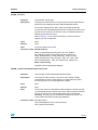
2.2.5
AC induction motor parameters: MC_ACmotor_param.h
The MC_ACmotor_param.h header file holds motor parameters which are essential to
properly operate the IFOC vector drive.
The following parameters must be defined in all cases:
●
#define ROTOR_TIME_CONSTANT
Define here (in µs), the rotor open circuit time constant of the motor τ r :
τr =
Lr Lm + Llr
=
rr
rr
where Lm is the magnetizing inductance, Llr is the rotor leakage inductance, Lr is the
rotor inductance, rr is the rotor resistance.
●
#define POLEPAIR_NUMBER
Define here the stator winding pole pair number;
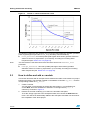
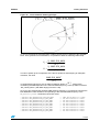
●
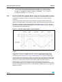
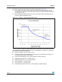
#define RATED_FREQ
Define here (in 0.1Hz) the right-hand boundary of the constant torque region (see
Figure 8): in that region we have rated current, rated flux, rated torque, rated power;
●
hNominal_Flux
Define here the required magnetizing current im (positive, peak value), expressed in
q1.15 format (see Section A.3 on page 99).
23/105
Getting started with the library
Figure 8.
UM0324
Torque vs. speed characteristic curve
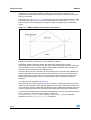
The following parameters are required only to enter the field weakening operation (constant
power region begins beyond the RATED_FREQ boundary mentioned above):
●
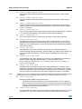
Note:
The first element of the table should have the same value as the hNominal_Flux
parameter.
●
2.3
hFlux_Reference: this look-up table (256 signed 16-bit values) provides reference
values of current ids (expressed in q1.15 format), according to increasing stator
frequencies (see Section 4.4.4 on page 63);
hTorque_Reference : this look-up table (256 signed 16-bit values) provides
saturation values of current iqs (expressed in q1.15 format), according to increasing
stator frequencies (see Section 4.4.4 on page 63).
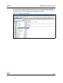
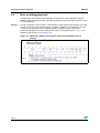
How to define and add a c module
This section describes with an example how to define and include a new module in a project
based on the library. The example is based on the addition of two files: my_file.c and the
corresponding header file my_file.h.
1.
Create a new file.
You can either copy and paste an existing file and rename it, or in the File menu,
choose New, then click the File icon and save it in the right format (*.c, *.h
extension), as shown in Figure 9.
2.
Declare the new file containing your code in the toolchain workspace.
To do this, simply right-click in the workspace folder, then choose the Add Files submenu. The new file is automatically added to the workspace and taken into account for
the compilation of the whole project.
24/105
UM0324
Getting started with the library
The procedure of adding the module to the project is very easy with the IAR Embedded
Workbench, as the makefile and linking command files are automatically generated. When
rebuilding the library, the configuration files are updated accordingly.
Figure 9.
Adding a new module
25/105
Running the demo program
3
UM0324
Running the demo program
This section assumes that you are using the STR750-MCKIT motor control kit.
The demo program is intended to provide examples on how to use the software library
functions; it includes both open speed loop and closed speed loop operations (hereafter
simply referred to as Open Loop and Closed Loop), with the possibility of varying different
parameters on the fly.
The default configuration allows the use of three shunt resistor for stator current reading and
tacho generator for speed feedback. Refer to Section 3.3 on page 30 for setting up the
system when using ICS, and to Section 3.4 on page 32 if using quadrature incremental
encoder.
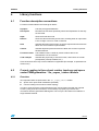
After the MCU initialization phase, a welcome message appears, and shortly after the main
window is displayed. Use the joystick and the button labelled KEY to navigate between the
menus.
Key assignments are shown in Figure 10.
Figure 10. Key function assignments
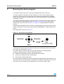
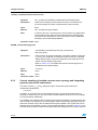
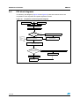
A simple state machine handles the motor control tasks in the main loop, as well as basic
monitoring of the power stage. This state machine does not differentiate open from closed
loop control. It is described in Figure 11.
The power stage is monitored using the ADC peripheral and the PWM peripheral
Emergency Stop (ES) input to watch the following conditions:
●
Heatsink over-temperature (ADC channel AIN6 and ES input),
●
DC bus over-voltage (on ADC channel AIN7),
●
Over-current protection (ES input).
Any of these three conditions will cause the PWM to be stopped and the state machine to go
into FAULT state for 2 seconds before coming back to IDLE state. Depending on the source
of the fault, an error message is also displayed on the LCD during FAULT state.
26/105
UM0324
Running the demo program
Figure 11. Main.c state machine
3.1
Open loop
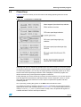
Figure 12 shows a summary of the LCD menus and settings (blinking items are shown
underlined).
Figure 12. LCD menus in open loop
Switching from open to closed loop operation and vice versa is done by moving the joystick
up or down while the first menu shown in Figure 12 is displayed and the motor is stopped.
27/105
Running the demo program
UM0324
Moving the joystick left or right in these circumstances allows changing the context into the
second menu where it is possible to modify both the torque and flux reference.
Finally press either the KEY button or the joystick to start the motor (main state machine will
move from IDLE to START state).
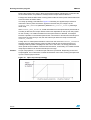
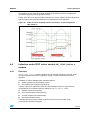
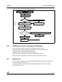
The ramp up strategy is illustrated in Figure 13. Basically, the applied torque reference
reaches the final Iq value set with the joystick in the time that you configure in the
STARTUP_RAMP_DURATION parameter (defined in MC_Control_Param.h) following a
linear ramp.
After STARTUP_RAMP_DURATION, if valid information from the speed sensor (tachometer or
encoder) is detected, the torque reference becomes adjustable on the fly from the joystick.
On the contrary, if no valid information from the speed sensor is detected, for example
because a problem occurred with speed sensor connections or because the load torque is
higher then the value that you set, then the final torque reference is kept constant until
STARTUP_TIMEOUT.
Finally, when no valid speed information comes from the motor and STARTUP_TIMEOUT is
elapsed, the main state machine goes into FAULT state for two seconds and the error
message ‘Start-up failed’ is displayed on the LCD. In this case, it is strongly advised to
check speed sensor feedback connections first and then, if necessary, to increase the final
ramp torque reference in case the load torque is too high.
Caution:
In open loop operation, a constant torque reference is produced. Depending on the load
torque applied, this could lead to constant acceleration of the motor, making the speed rise
up to the motor’s physical limits.
Figure 13. Open loop start-up strategy
28/105
UM0324
3.2
Running the demo program
Closed loop
Figure 14 shows a summary of the LCD menus and settings (blinking items are shown
underlined).
Figure 14.
LCD menus in closed loop
Switching from open to closed loop operation and vice versa is done by moving the joystick
up or down while the first menu shown in the above figure is displayed and motor is stopped.
In closed loop operation, you can vary the target speed by moving the joystick up or down
while the PID motor speed target selection menu is displayed. The demo program also
allows real-time tuning of the speed PID regulator coefficients.
Finally, although you cannot act directly on torque and flux references, you can also observe
both the target and measured flux and torque stator current component. In fact, in closed
loop, both flux and torque references are the outputs of speed PID regulator and field
weakening blocks.
As in open loop, pressing the joystick or the KEY button will start the motor.
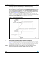
The closed loop ramp-up strategy is shown in Figure 15. Basically, a linear torque ramp is
applied to the motor until it reaches speed TACHO_SPEED_VAL (if a tacho speed sensor is
used) or ENCODER_CL_ENABLE (if an encoder is used). Then, the speed PID regulator is
enabled and takes control of the torque reference.
29/105
Running the demo program
UM0324
However, if the motor does not reach the above mentioned speeds before
STARTUP_RAMP_DURATION, the final torque reference value (STARTUP_FINAL_TORQUE)
is further applied until STARTUP_TIMEOUT. Finally, in the case where the speeds that
enable the closed loop are not reached before STARTUP_TIMEOUT, the state machine goes
into FAULT state for two seconds and the error message Start-up failed is displayed on the
LCD. In this case, it is strongly advised to check speed sensor feedback connections first
and then, if necessary, to increase STARTUP_FINAL_TORQUE if the load torque is too high.
With reference to Figure 15, note that parameters TACHO_SPEED_VAL,
ENCODER_CL_ENABLE, STARTUP_FINAL_TORQUE, STARTUP_RAMP_DURATION, and
STARTUP_TIMEOUT are fully configurable so that you can customize the start-up depending
on the motor and load conditions. Parameters definitions are done in the
MC_Control_Param.h header file.
Figure 15. Closed loop start-up strategy
3.3
Setting up the system when using ICS sensors
The default configuration provides for the use of three shunt resistors and tacho-generator.
Section 3.3.1 describes how to change the firmware configuration from three shunt resistors
to two ICS stator current reading. This section gives you information about how to provide
the STR750 with ICS feedback signals and to properly customize the firmware.
Caution:
30/105
When using two ICS for stator current reading, you must ensure that the conditioned
sensors output signal range is compatible with the STR750 supply voltage.
UM0324
3.3.1
Running the demo program
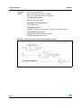
Connecting the two ICS sensors to the motor and to STR750
In order for the implemented IFOC algorithm to work properly, it is necessary to ensure that
the software implementation of the 75x_svpwm_ICS module and the hardware connections
of the two ICS are consistent.
As illustrated in Figure 16, the two ICS must act as transducers on motor phase currents
coming out of the inverter legs driven by STR750 PWM signals PWM1 (Phase A) and
PWM2 (Phase B). In particular, the current coming out of inverter Phase A must be read by
an ICS whose output has to be sent to the analog channel specified by the
PHASE_A_CHANNEL parameter in MC_pwm_ics_prm.h. Likewise, the current coming out
of inverter Phase B must be read by the other ICS and its output has to be sent to the
analog channel specified by the PHASE_B_CHANNEL parameter in MC_pwm_ics_prm.h.
About the positive current direction convention, a positive half-wave on
PHASE_X_CHANNEL is expected, corresponding to a positive half-wave on the current
coming out of the related inverter leg (see direction of I in Figure 16).
Figure 16. ICS hardware connections
3.3.2
Selecting PHASE_A_CHANNEL and PHASE_B_CHANNEL
Default settings for PHASE_A_CHANNEL and PHASE_B_CHANNEL are respectively
ADC_CHANNEL11 and ADC_CHANNEL10. You can change the default settings if the
hardware requires it by editing the MC_pwm_ics_prm.h file. However, there are a few rules
to follow when selecting the new ADC channels:
●
You must initialize the proper GPIOs as analog inputs; an example for channel 8 is
given below:
/* ADC Channel 8 pin configuration */
GPIO_InitStructure.GPIO_Mode = GPIO_Mode_AIN;
GPIO_InitStructure.GPIO_Pin = GPIO_Pin_29;
GPIO_Init(GPIO0, &GPIO_InitStructure);
31/105
Running the demo program
●
3.4
UM0324
You must select two contiguous channels (for example, ADC_CHANNEL8 and
ADC_CHANNEL9) and the one with the highest number must be associated with
PHASE_A_CHANNEL (for example, PHASE_A_CHANNEL -> ADC_CHANNEL9,
PHASE_B_CHANNEL->ADC_CHANNEL8) .
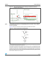
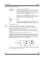
How to build the system when using an incremental encoder
Quadrature incremental encoders are widely used to read the rotor position of electric
machines.
As the name implies, incremental encoders actually read angular displacements with
respect to an initial position: if that position is known, then rotor absolute angle is known too.
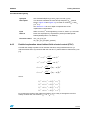
Quadrature encoders have two output signals (represented in Figure 17 as TI1 and TI2).
With these, and with the STR750 standard timer in encoder interface mode, it is possible to
get information about rolling direction.
Figure 17. Encoder output signals: counter operation
In addition, rotor angular velocity can be easily calculated as a time derivative of angular
position.
To set up the AC IM IFOC software library for use with an incremental encoder, simply
modify the 75x_MCconf.h and MC_encoder_param.h header files according to the
indications given in Section 2.2.1 on page 18 and Section 2.2.3 on page 21 respectively.
However, some extra care should be taken, concerning what is considered to be the positive
rolling direction: this software library assumes that the positive rolling direction is the rolling
direction of a machine that is fed with a three-phase system of positive sequence.
Because of this, and because of how the encoder output signals are wired to the
microcontroller input pins, it is possible to have a sign discrepancy between the real rolling
direction and the direction that is read. To avoid this kind of reading error, you can apply the
following procedure:
32/105
UM0324
Running the demo program
1.
Set the DC source at low voltage (50V).
2.
Run the system in closed loop operation, and on the LCD, observe the target and
measured speeds.
The error occurs if the sign of the measured speed is opposite to the sign of the target
speed. (For help with the LCD menus see Section 3.2 on page 29):.
3.
If the error occurs, you can correct it by simply swapping and rewiring the encoder
output signals.
If this isn’t practical, you can modify a software setting instead: in the 75x_encoder.c
file, replace the code line:
TIM_InitStructure.TIM_IC1Polarity = TIM_IC1Polarity_Rising;
with:
TIM_InitStructure.TIM_IC1Polarity = TIM_IC1Polarity_Falling;
3.5
Fault messages
This section provides a list of possible fault message that can be displayed on the LCD
when using the software library together with the STR750MC-KIT:
●
“Over Current”
An Emergency Stop was detected on the PWM peripheral dedicated pin. If using
STR750-MCKIT it could mean that either the hardware over temperature protection or
the hardware over current protection were triggered. Refer to the STR750-MCKIT User
Manual for details,
●
“Over Heating”
An over temperature was detected on the dedicated analog channel; the digital
threshold NTC_THRESHOLD and the relative hysteresis (NTC_HYSTERESIS) are
specified in the MC_Misc.c source file. Refer to the STR750-MCKIT User Manual for
details.
●
“Tacho timed out”
The speed feedback timed out. Verify speed sensor connections.
●
“Start up failed”
The motor ramp-up failed. Refer to Section 3.1 and Section 3.2 for in-depth information,
●
“Bus Over Voltage”
An over voltage was detected on the dedicated analog channel. The digital threshold
(OVERVOLTAGE_THRESHOLD) is specified in the MC_Misc.c source file. Refer to the
STR750-MCKIT User Manual for details.
●
"Bus Under Voltage"
The bus voltage is below 20V DC. This threshold is specified in the
UNDERVOLTAGE_THRESHOLD parameter in the MC_Misc.c source file.
Note:
The corresponding FAULT flag is not cleared by firmware, therefore the STR750 must be
reset after the bus voltage has been switched on.
33/105
Running the demo program
3.6
UM0324
Note on debugging tools
The third party JTAG interface should always be isolated from the application using the
MB535 JTAG opto-isolation board; it provides protection for both the JTAG interface and the
PC connected to it.
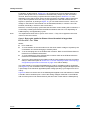
Caution:
During a breakpoint, when using the JTAG interface for the firmware development, the motor
control cell clock circuitry should always be enabled; if disabled, a permanent DC current
may flow in the motor because the PWM outputs are enabled, which could cause
permanent damage to the power stage and/or motor. A dedicated bit in the PWM_CR, the
DBGC bit must be set to 1 (see Figure 18).
Figure 18. DBGC bit in PWM control register (extract from STR750 reference
manual)
Control Register (PWM_CR)
Address Offset: 00h
Reset value: 0000h
34/105
UM0324
Library functions
4
Library functions
4.1
Function description conventions
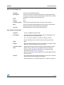
Functions are described in the format given below:
Synopsis
Lists the prototype declarations.
Description
Describes the functions specifically with a brief explanation of how they
are executed.
Input
Gives the format and units.
Returns
Gives the value returned by the function, including when an input value
is out of range or an error code is returned.
Note
Indicates the limits of the function or specific requirements that must be
taken into account before implementation.
Caution
Indicates important points that must be taken into account to prevent
hardware failures.
Functions called
Lists called functions. Useful to prevent conflicts due to the
simultaneous use of resources.
Code example
Indicates the proper way to use the function, and if there are certain
prerequisites (interrupt enabled, etc.).
Some of these sections may not be included if not applicable (for example, no parameters or
obvious use).
4.2
Current reading in three shunt resistor topology and space
vector PWM generation: 75x_svpwm_3shunt module
4.2.1
Overview
Two important tasks are performed in the 75x_svpwm_3shunt module:
●
Space vector pulse width modulation (SVPWM)
●
Current reading in three shunt resistor topology
In order to reconstruct the currents flowing through a three-phase load with the required
accuracy using three shunt resistors, it is necessary to properly synchronize A/D
conversions with the generated PWM signals. This is why the two tasks are included in a
single software module.
35/105
Library functions
4.2.2
UM0324
List of available functions
The following is a list of available functions as listed in the 75x_svpwm_3shunt.h header
file:
●
SVPWM_3ShuntInit on page 36
●
SVPWM_3ShuntCurrentReadingCalibration on page 37
●
SVPWM_3ShuntGetPhaseCurrentValues on page 37
●
SVPWM_3ShuntCalcDutyCycles on page 38
●
SVPWM_3ShuntGPADCConfig on page 38
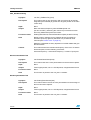
SVPWM_3ShuntInit
Synopsis
void SVPWM_3ShuntInit(void);
Description
The purpose of this function is to set-up microcontroller peripherals for
performing 3 shunt resistor topology current reading and center aligned
PWM generation.
The function initializes DMA, EIC, ADC, GPIO, PWM, TIM0 peripherals.
In particular, the DMA, ADC, PWM and TIM0 peripherals are configured
to perform two synchronized A/D conversions per PWM switching
period.
Refer to Section 4.2.3 for further information.
Input
None.
Returns
None.
Note
It must be called at main level.
Functions called Standard library:
MRCC_PeripheralClockConfig, GPIO_Init, EIC_IRQInit, EIC_IRQCmd,
DMA_Init, DMA_Cmd, TIM_DMAConfig, DMA_DeInit, ADC_DMACmd,
PWM_DeInit, PWM_StructInit, PWM_Init, PWM_TRGOSelection,
PWM_ClearFlag, PWM_ITConfig, PWM_ResetCounter,
ADC_StructInit, ADC_Init, ADC_Cmd, ADC_StartCalibration,
ADC_ConversionCmd, TIM_Init, TIM_SynchroConfig,
TIM_ResetCounter, PWM_Cmd.
Motor control library:
SVPWM_3ShuntCurrentReadingCalibration
36/105
UM0324
Library functions
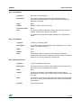
SVPWM_3ShuntCurrentReadingCalibration
Synopsis
void SVPWM_3ShuntCurrentReadingCalibration(void);
Description
The purpose of this function is to store the three analog voltages
corresponding to zero current values for compensating the offset
introduced by the amplification network.
Input
None.
Returns
None.
Note
This function must be called before PWM outputs are enabled so that
the current flowing through inverter legs is zero. When using STR750
MC Kit, the power board (MB459B) must be supplied before the
control board (MB469B). This way, the current sensing conditioning
network will reach steady state before performing calibration.
Functions called
Standard library:
ADC_GetFlagStatus, ADC_ConversionCmd, ADC_Init,
ADC_ClearFlag, ADC_ITConfig
Motor control library:
SVPWM_3ShuntCalcDutyCycles
SVPWM_3ShuntGetPhaseCurrentValues
Synopsis
Curr_Components SVPWM_3ShuntGetPhaseCurrentValues(void);
Description
This function computes current values of Phase A and Phase B in
q1.15 format starting from values acquired from the A/D Converter
peripheral.
Input
None.
Returns
Curr_Components type variable.
Note
In order to have a q1.15 format for the current values, the digital value
corresponding to the offset must be subtracted when reading phase
current A/D converted values. Therefore, the function must be called
after SVPWM_3ShuntCurrentReadingCalibration.
Functions called None.
37/105
Library functions
UM0324
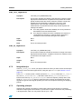
SVPWM_3ShuntCalcDutyCycles
Synopsis
void SVPWM_3ShuntCalcDutyCycles (Volt_Components
Stat_Volt_Input);
Description
After execution of the IFOC algorithm, new stator voltage components
Vα and Vβ are computed. The purpose of this function is to calculate
exactly the three duty cycles to be applied to motor phases from the
values of these voltage components.
Moreover, once the three duty cycles to be applied in next PWM period
are known, this function sets the DMA, ADC and TIM0 peripherals for
the next current reading. In particular, depending on the duty cycle
values, the delay for the two current samplings are computed (see
Section 4.2.5 on page 43).
Refer to Section 4.2.3 for information on the theoretical approach of
SVPWM.
Input
Vα and Vβ
Returns
None.
Note
None.
Functions called None.
SVPWM_3ShuntGPADCConfig
Synopsis
void SVPWM_3ShuntGPADCConfig(void);
Description
The purpose of this function is to configure the A/D converter for
general purpose conversions after conversions for current reading
have been performed. In particular, this function starts a chain of
regular conversions whose first channel is
GP_CONVERSIONS_FIRST_CHANNEL (defined in
‘MC_pwm_3shunt_prm.h’). In addition, the number of channels to be
converted is set equal to GP_CONVERSIONS_NUMBER (defined in
‘MC_pwm_3shunt_prm.h’).
Input
None
Returns
None
Note
As mentioned in Section 4.2.3, the overall duration of the regular chain
conversion must be lower than the duration of the IFOC_Model
routine. This limits to 6 (at 7.5MHz ADC peripheral clock) the number
of channels that can be converted in one PWM period.
Functions called None
38/105
UM0324
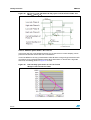
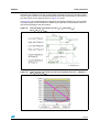
4.2.3
Library functions
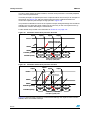
Space vector PWM implementation
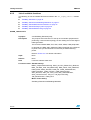
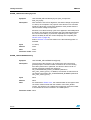
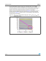
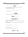
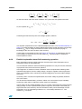
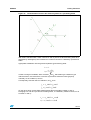
Figure 19 shows the Stator Voltage components Vα and Vβ while Figure 20 illustrates the
corresponding PWM for each of the six space vector sectors:
Figure 19. Vα and Vβ stator voltage components
Figure 20. SVPWM phase voltages waveforms
39/105
Library functions
UM0324
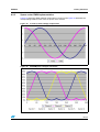
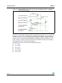
With the following definitions for:
U α = 3 ∗ T ∗ Valfa
U β = T ∗ Vbeta
and
X =Uβ
Y=
Z=
Uα + U β
2
U β − Uα
2
literature demonstrates that the space vector sector is identified by the conditions shown in
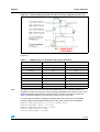
Table 1.
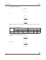
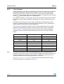
Table 1.
Sector identification
Y<0
Z<0
Sector
V
Y>=0
Z>=0
Z<0
Z>=0
X<=0
X<0
X<=0
X>0
IV
III
VI
I
II
The duration of the positive pulse widths for the PWM applied on Phase A, B and C are
respectively computed by the following relationships:
Sector I, IV:
T + X −Z
2
tB = tA + Z
tC = t B − X
tA =
Sector II, V:
T +Y − Z
2
tB = tA + Z
tC = t A − Y
tA =
40/105
UM0324
Library functions
Sector III, VI:
T − X +Y
2
t B = tC + X
tC = t A − Y
tA =
Where T is the PWM period.
Now, considering that the PWM pattern is center aligned and that the phase voltages must
be centered at 50% of duty cycle, it follows that the values to be loaded into the PWM output
compare registers are given respectively by:
Sector I, IV:
T T /2+ X −Z
+
4
2
TimePhB = TimePhA + Z
TimePhC = TimePhB − X
TimePhA =
Sector II, V:
T T /2+Y − Z
+
4
2
TimePhB = TimePhA + Z
TimePhC = TimePhA − Y
TimePhA =
Sector III, VI:
T T /2− X +Y
+
4
2
hTimePhB = TimePhC + X
TimePhC = TimePhA − Y
TimePhA =
4.2.4
Current sampling in three shunt topology and general purpose A/D
conversions
The three currents I1, I2, and I3 flowing through a three-phase system follow the
mathematical relation:
I1+I2+I3=0
For this reason, to reconstruct the currents flowing through a generic three-phase load, it is
sufficient to sample only two out of the three currents while the third one can be computed
by using the above relation.
The flexibility of the STR750 A/D converter trigger, makes it possible to synchronize the two
A/D conversions needed for reconstructing the current flowing through the three-phase AC
induction motor at any given time along the PWM period. To do this, the control algorithm
must have a full control of the A/D converter peripheral.
41/105
Library functions
UM0324
Furthermore, you have the possibility to add any A/D conversions required for your
application (hereafter referred to as general purpose conversions). This section describes
how this is achieved.
First of all, the SVPWM_3ShuntInit function performs the synchronization between PWM
and TIM0 peripherals (Figure 21 shows the two peripheral counters when REP_RATE = 1),
then, the A/D converter peripheral is configured so that it is triggered by the TIM0 OC2
signal.
Figure 21. PWM and TIM0 synchronization (REP_RATE=1)
This way, when the value of the TIM0 counter matches the value contained in the OCR2
register, the first A/D conversion for current sampling is started.
Meanwhile, a DMA transaction reloads the TIM0 OCR2 register with the value
corresponding to the delay required for the second current sampling conversion. Moreover,
the end of this first A/D conversion triggers another DMA transaction which sets the next
channel to be converted in the ADC register CLR2.
At the end of the second conversion, the three-phase load current has been updated and
the IFOC algorithm can then be executed in the A/D End of Conversion Interrupt Service
Routine (EOC ISR). In this routine, the A/D converter is also reconfigured so that it can
perform the general purpose chain of conversions while the CPU executes the IFOC
algorithm.
The entire process is illustrated in Figure 22.
After execution of the IFOC algorithm, the A/D converter is configured to perform the next
PWM period three-phase current sensing (delays and channels). This allows to reduce the
CPU load (lower number of ADC ISR) and limits to 6 (@ 7.5 MHz ADC peripheral clock) the
number of general purpose A/D conversions that can be performed in each PWM period.
To specify the general purpose conversions to be performed, you can select the first channel
and the number of channels to be converted by editing the
GP_CONVERSIONS_FIRST_CHANNEL and GP_CONVERSIONS_NUMBER parameters
respectively in the MC_pwm_3shunt_prm.h header file.
42/105
UM0324
Library functions
Figure 22. Three shunt topology current sampling and GP A/D conversions
integration (REP_RATE=1)
4.2.5
Tuning delay parameters and sampling stator currents in three shunt
resistor topology
Figure 23 shows one of the three inverter legs with the related shunt resistor:
Figure 23. Inverter leg and shunt resistor position
To indirectly measure the phase current I, it is possible to read the voltage V providing that
the current flows through the shunt resistor R.
It is possible to demonstrate that, whatever the direction of current I, it always flows through
the resistor R if transistor T2 is switched on and T1 is switched off. This implies that in order
to properly reconstruct the current flowing through one of the inverter legs, it is necessary to
properly synchronize the conversion start with the generated PWM signals. This also means
that current reading cannot be performed on a phase where the duty cycle applied to the low
side transistor is either null or very short.
43/105
Library functions
UM0324
Fortunately, as discussed in Section 4.2.4,to reconstruct the currents flowing through a
generic three-phase load, it is sufficient to simultaneously sample only two out of three
currents, the third one being computed from the relation given in Section 4.2.4. Thus,
depending on the space vector sector, the A/D conversion of voltage V will be performed
only on the two phases where the duty cycles applied to the low side switches are the
highest. In particular, by looking at Figure 20, you can deduct that in sectors 1 and 6, the
voltage on the Phase A shunt resistor can be discarded; likewise, in sectors 2 and 3 for
Phase B, and finally in sectors 4 and 5 for Phase C.
Moreover, in order to properly synchronize the two stator current reading A/D conversions, it
is necessary to distinguish between the different situations that can occur depending on
PWM frequency and applied duty cycles.
Note:
The explanations below refer to space vector sector 1. They can be applied in the same
manner to the other sectors.
Case 1: Duty cycle applied to Phase A low side switch is larger than
DT+TN+ 2TS + TH + TDMA
Where:
●
DT is dead time.
●
TN is the duration of the noise induced on the shunt resistor voltage of a phase by the
commutation of a switch belonging to another phase.
●
TS is the sampling time of the STR750 A/D converter. Refer to the STR750 reference
manual for more detailed information.
●
TH is the holding time of the STR750 A/D converter. Refer to the STR750 reference
manual for more detailed information.
●
TDMA is the time required for the DMA to load the value related to the next conversion
delay in TIM0 OCR2 (refer to Section 4.2.4: Current sampling in three shunt topology
and general purpose A/D conversions on page 41 for further details).
This case typically occurs when SVPWM with low (<60%) modulation index is generated
(see Figure 24). The modulation index is the applied phase voltage magnitude expressed as
a percentage of the maximum applicable phase voltage (the duty cycle ranges from 0% to
100%).
Figure 25 offers a reconstruction of the PWM signals applied to low side switches of Phase
A and B in these conditions plus a view of the analog voltages measured on the STR750
A/D converter pins for both Phase B and C (the time base is lower than the PWM period).
44/105
UM0324
Library functions
Figure 24. Low side switches gate signals (low modulation indexes)
Note that these current feedbacks are constant in the view in Figure 25 because it is
assumed that commutations on Phase B and C have occurred out of the visualized time
window.
Moreover, it can be observed that in this case the two stator current sampling conversions
can be performed between the two commutations of the Phase A low side switch, as shown
in Figure 25.
Figure 25. Low side Phase A duty cycle > DT+TN+ 2TS + TH + TDMA
After the commutation of the Phase A low side switch, a blanking window equal to TN is
applied before starting conversion of phase C, then at the end of the first conversion, it is
necessary to wait a TDMA period before starting the phase B conversion.
45/105
Library functions
UM0324
Case 2: DT+TN+TS < Phase A duty cycle < DT+TN+ 2TS + TH + TDMA
In this case, only one of the two conversions can be performed between the two Phase A
low side commutations. The other conversion is then synchronized depending on the
difference of duty cycles between Phase B and A (ΔDutyA-B). In particular if
ΔDutyA-B < DT+TN+TS (as shown in the red circle in Figure 26), the sampling of Phase C
cannot be performed between Phase B low side switching on and Phase A high side
switching off (see Figure 27). Therefore, Phase C current sampling is performed before
Phase B high side commutation.
Figure 26. DT+TN+TS< Low side Phase A duty cycle < DT+TN+2TS+TH+TDMA and
ΔDutyA-B<DT+TN+TS
46/105
UM0324
Library functions
Figure 27. DT+TN+TS < Low side Phase A duty cycle < DT+TN+2TS+TH+TDMA and
ΔDutyA-B<DT+TN+TS
On the contrary, if ΔDutyA-B > DT+TN+TS (as shown in the red circle in Figure 28), Phase C
conversion is performed between Phase B low side switch on and Phase A high side switch
off (see Figure 29).
Figure 28. DT+TN+TS < Low side Phase A duty cycle < DT+TN+2TS+TH+TDMA and
ΔDutyA-B>DT+TN+TS
47/105
Library functions
UM0324
Figure 29. DT+TN+TS < Low side Phase A duty cycle < DT+TN+2TS+TH+TDMA and
ΔDutyA-B>DT+TN+TS
Case 3: Phase A pulse width < DT+TN+TS
In this case, the duty cycle applied to Phase A is so short that no current sampling can be
performed in between the two low side commutations.
Then if the difference of duty cycles between Phase B and A is long enough to allow two A/D
conversions to be performed between Phase B low side switch on and Phase A high side
switch off, the strategy shown in Figure 31 is used.
Figure 30. Low side duty cycle Phase A < DT+TN+TS and
ΔDutyA-B > DT+TN+2TS+TH+TDMA
48/105
UM0324
Library functions
Otherwise, if the difference of duty cycles between Phase B and A is long enough to allow
only one A/D conversion to be performed between Phase B low side switch on and Phase A
high side switch off, the strategy shown in Figure 33 is used.
In Figure 33, TRise represents the time required by the analog voltage on the shunt resistor
of a phase (signal ‘Current feedback of Phase B’) to settle after a commutation of the low
side switch belonging to the same phase.
Figure 31. Low side duty cycle Phase A < DT+TN+TS and ΔDutyA-B >
DT+TN+2TS+TH+TDMA
Figure 32. Low side duty cycle Phase A < DT+TN+TS and DT+TRise+TS < ΔDutyA-B <
DT+TN+2TS+TH+TDMA
49/105
Library functions
UM0324
Figure 33. Low side duty cycle Phase A < DT+TN+TS and DT+TRise+TS < ΔDutyA-B <
DT+TN+2TS+TH+TDMA
Finally, when a high modulation index (> 92%) and high frequency (>11kHz) PWM signal is
generated, it could happen that both Phase A pulse width is lower than DT+TN+TS and that
ΔDutyA-B < DT+TRise+TS. In this case, it is not possible to perform the current reading on
Phase B, (see Figure 34), so the PWM patterns are slightly modified to relapse in the case
shown in Figure 33. Because this PWM pattern modification produces a distortion on the
phase currents, it is better to limit the scope of the modification by limiting the modulation
index depending on the selected PWM frequency.
Specifically, this can be done with the following default values:
50/105
●
DT = 0.7µs
●
TN = 2.55µs
●
TS = 1.6µs
●
TH = 2.67µs
●
TDMA = 0.7µs
●
TRise =2.6µs
UM0324
Library functions
Figure 34. Low side duty cycle Phase A < DT+TN+TS and ΔDutyA-B< DT+TRise+TS
The maximum applicable duty cycles are listed in Table 2 as a function of the PWM
frequency.
Table 2.
Note:
PWM frequency vs maximum duty cycle relationship
PWM frequency
Max duty cycle
Max modulation index (MMI)
Up to 11.4kHz
100%
100%
12.2kHz
99.5%
99%
12.9kHz
99%
98%
13.7kHz
98.5%
97%
14.4kHz
98%
96%
15.2kHz
97.5%
95%
16kHz
97%
94%
16.7kHz
96.5%
93%
17.5kHz
96%
92%
The figures above were measured using the MB459 board. This evaluation platform is
designed to support several motor driving topologies (PMSM and AC induction) and current
reading strategies (single and three shunt resistors). Therefore, the figures provided in
Table 2 should be understood as a starting point and not as a best case.
You can further increase the maximum applicable duty when using your own hardware
system by editing the following definitions in the MC_pwm_3shunt_prm.h header file:
#define
#define
#define
#define
#define
HOLD_TIME 0xA0 //2.67usec 1/60MHz units
DMA_TIME 0x2A //0.7usec
SAMPLING_TIME 0x60//1.6usec
TNOISE 0x9c//2.6usec
TRISE 0x9c //2.6usec
51/105
Library functions
4.3
Isolated current sensor reading and space vector PWM
generation: 75x_svpwm_ICS module
4.3.1
Overview
UM0324
Two important tasks are performed in the 75x_svpwm_ICS module.
●
Space vector pulse width modulation (SVPWM),
●
Three-phase current reading when two isolated current sensors (ICS) are used.
In order to reconstruct the currents flowing through a three phase load with the required
accuracy using two ICS’, it is necessary to properly synchronize A/D conversions with the
generated PWM signals. This is why the two tasks are included in a single software module.
4.3.2
List of available functions and interrupt service routines
The following is a list of available functions as listed in the 75x_svpwm_ICS.h header file:
●
SVPWM_IcsInit on page 53
●
SVPWM_IcsCurrentReadingCalibration on page 53
●
●
52/105
SVPWM_IcsGetPhaseCurrentValues on page 54
SVPWM_IcsCalcDutyCycles on page 54
UM0324
Library functions
SVPWM_IcsInit
Synopsis
void SVPWM_IcsInit(void);
Description
The purpose of this function is to set-up microcontroller peripherals for
performing ICS reading and center aligned PWM generation.
The function initializes EIC, ADC, GPIO, and PWM peripherals.
In particular ADC and PWM peripherals are configured to perform one
injected chain of two A/D conversions every time PWM registers are
updated (event called U event).
Refer to Section 4.3.3 for further information on A/D conversion
triggering in ICS configuration.
Input
None.
Returns
None.
Note
It must be called at main level.
Functions called Standard library:
MRCC_PeripheralClockConfig, GPIO_Init, EIC_IRQInit,
EIC_IRQCmd, PWM_DeInit, PWM_StructInit, PWM_Init,
PWM_TRGOSelection, PWM_ClearFlag, PWM_ITConfig,
PWM_ResetCounter, ADC_StructInit, ADC_Init, ADC_Cmd,
ADC_StartCalibration, ADC_ConversionCmd, PWM_Cmd.
Motor control library:
SVPWM_IcsCurrentReadingCalibration
SVPWM_IcsCurrentReadingCalibration
Synopsis
void SVPWM_IcsCurrentReadingCalibration(void);
Description
The purpose of this function is to store the two analog voltages
corresponding to zero current values for compensating the offset
introduced by both ICS and amplification network.
Input
None.
Returns
None.
Note
The function must be called before PWM outputs are enabled so that
current flowing through inverter legs is zero. When using the STR750
MC Kit, ICS sensors must be supplied before the control board
(MB469B). This way, the current sensing conditioning network can
reach steady state before performing calibration.
Functions called Standard Library:
ADC_GetFlagStatus, ADC_ConversionCmd,
ADC_GetConversionValue
53/105
Library functions
UM0324
SVPWM_IcsGetPhaseCurrentValues
Synopsis
Curr_Components SVPWM_IcsGetPhaseCurrentValues(void);
Description
This function computes current values of Phase A and Phase B in
q1.15 format from the values acquired from the A/D converter.
Input
None.
Returns
Curr_Components type variable
Note
In order to have a q1.15 format for the current values, the digital value
corresponding to the offset must be subtracted when reading phase
current A/D converted values. Thus, the function must be called after
SVPWM_IcsCurrentReadingCalibration.
Functions called None.
SVPWM_IcsCalcDutyCycles
Synopsis
void SVPWM_IcsCalcDutyCycles (Volt_Components
Stat_Volt_Input);
Description
After execution of the IFOC algorithm, new stator voltages component
Vα and Vβ are computed. The purpose of this function is to calculate
exactly the three duty cycles to be applied to motor phases from the
values of these voltage components.
Refer to Section 4.2.3 for details about the theoretical approach of
SVPWM and its implementation.
4.3.3
Input
Vα and Vβ
Returns
None.
Note
None.
Functions called
None.
Current sampling in isolated current sensor topology and integrating
general purpose A/D conversions
The three currents I1, I2, and I3 flowing through a three-phase system follow the
mathematical relationship:
I1+I2+I3=0
Therefore, to reconstruct the currents flowing through a generic three-phase load, it is
sufficient to sample only two out of the three currents while the third one can be computed
by using the above relationship.
The flexibility of the STR750 A/D converter trigger makes it possible to synchronize the two
A/D conversions necessary for reconstructing the stator currents flowing through the threephase AC induction motor with the PWM reload register updates. Tthe update rate can be
adjusted using the repetition counter. This is important because, as shown in Figure 35, it is
precisely during counter overflow and underflow that the average level of current is equal to
54/105
UM0324
Library functions
the sampled current. Refer to the STR750 Reference Manual to learn more about A/D
conversion triggering and the repetition counter.
Finally, at the end of the injected chain conversion for current reading, the general purpose
A/D conversions are performed while the CPU executes the IFOC algorithm.
Figure 35. Stator currents sampling and GP conversions in ICS configuration
(REP_RATE=1)
4.4
Induction motor IFOC vector control: MC_IFOC_Drive.c
module
4.4.1
Overview
The MC_IFOC_Drive.c module, designed for AC induction machines, provides, at the
core, decoupled torque and flux regulation, relying on indirect field oriented control
algorithm.
In addition, it makes available other important features:
●
speed regulation by PID feedback control,
●
flux weakening for extended speed range.
It works, requiring no adjustment, with all of the selectable current or speed sensing
configurations (in accordance with the settings in the 75x_MCconf.h file):
●
isolated current sensing (ICS),
●
three shunt resistors current sensing,
●
encoder position and speed sensing,
●
tachometer speed sensing.
It handles several functions of other modules, and has no direct access on the
microcontroller peripheral registers.
55/105
Library functions
4.4.2
UM0324
List of available C functions
●
IFOC_Init on page 56
●
IFOC_Model on page 57
●
IFOC_CalcFluxTorqueRef on page 59
●
CalcIm on page 60
●
CalcRotFlxSlipFreq on page 61
IFOC_Init
56/105
Synopsis
void IFOC_Init(void)
Description
This function is normally called at every motor start-up. It performs
the initialization of some of the variables used for IFOC
implementation by the MC_IFOC_Drive.c module.
Input
None.
Returns
None.
Note
None.
Functions called
None.
UM0324
Library functions
IFOC_Model
Synopsis
void IFOC_Model (void)
Description
The purpose of this function is to perform AC-IM torque and flux
regulation, implementing the IFOC vector algorithm.
Current commands iqsλr * and idsλr * (which, under field oriented
conditions, can control machine torque and flux respectively) are defined
outside this function (in closed loop they are provided, by means of speed
and flux regulators, by the IFOC_CalcFluxTorqueRef function, while in
open-loop mode they are settled by the user).
Therefore, as a current source is required, the function has to run the
power converter as a CR-PWM. For this purpose, it implements an high
performance synchronous d,q frame current regulator, whose operating
frequency is defined, as explained in Section 2.2.2, by the parameter
REP_RATE (in conjunction with PWM_FREQ).
Triggered by ADC ECH / JECH ISR, the function loads stator currents
(read by ICS or shunt resistors) and carries out Clark and Park
transformations, converting them to iqsλr and idsλr (see Figure 7).
Then, these currents are fed to PID regulators together with reference
values iqsλr * and idsλr *. The regulator output voltages vqsλr * and vdsλr *
then must be transformed back to a stator frame (through Reverse Park
conversion), and finally drive the power stage.
In order to correctly perform Park and Reverse Park transformation, it is
essential to accurately estimate the rotor flux position (θ λr) (because
currents have to be oriented in phase and in quadrature with rotor flux). To
manage this task:
– function CalcIm is called to provide lm, that is the estimated value of the rotor
flux as a response to the variation of input current idsλr (see CalcIm function
description);
– function CalcRotFlxSlipFreq (see CalcRotFlxSlipFreq function description)
evaluates rotor flux slip frequency ωsλr (relying on known rotor time constant); if
using a tachogenerator, the rotor flux position θ λr is calculated by integrating the
sum of ωsλr and rotor electrical speed ω r (Figure 37) while, with an incremental
encoder, θ λr is determined by summing the rotor electrical angle and the
integral of ωsλr (Figure 36).
Input
None.
Returns
None.
57/105
Library functions
Functions
called
UM0324
CalcIm, CalcRotFlxSlipFreq;
Clarke, Park, RevPark_Circle_Limitation;
PID_Torque_Regulator, PID_Flux_Regulator;
If working with encoder:
ENC_Get_Electrical_Angle;
if Working with tachogenerator:
TAC_GetRotorFreq;
if working with ‘ICS’:
SVPWM_IcsGetPhaseCurrentValues, SVPWM_IcsCalcDutyCycles;
if working with ‘three shunt’:
SVPWM_3ShuntGetPhaseCurrentValues,
SVPWM_3ShuntCalcDutyCycles.
Figure 36. Rotor flux angle calculation (quadrature encoder)
58/105
UM0324
Library functions
Figure 37. Rotor flux angle calculation (tachogenerator)
IFOC_CalcFluxTorqueRef
Synopsis
void IFOC_CalcFluxTorqueRef (void)
Description
This function provides current components iqs* and ids* to be used
as reference values (by the IFOC_Model function) in closed-loop
speed mode (see “Torque & Flux opt” block in Figure 38).
Speed setpoint and actual rotor speed ωr are compared in a PID
control loop, whose output is iqs**. This component, together with
the previous flux reference and the rotor speed ωr, is used to work
out the stator frequency that has to be generated. With this
information, two lookup-tables (described in MC_ACmotor_prm,
Section 2.2.5 , defined by taking into account the field weakening
strategy explained in Section 4.4.4) are run through, in order to get
the optimal flux reference (ids*) and the saturation value of the
torque current component (iqs max) that allow to reach the desired
speed (under the obvious limitations of rated torque and rated
power).
Input
None.
Returns
None.
Functions called
PID_Speed_Regulator;
mul_q15_q15_q31, div_q31_q15_q15.
59/105
Library functions
UM0324
Figure 38. Torque and flux optimization block
CalcIm
Synopsis
s16 CalcIm (s16 hId_input);
Description
The purpose of this routine is to supply (to the calling function) the
estimated value of the rotor flux, as a response to variations of the
input current value idsλr (see “uncompensated flux response
controller” block in Figure 36 and Figure 37).
See Section 4.4.3 for in-depth information about the computations
implemented.
60/105
Input
Stator current idsλr in q1.15 format.
Returns
Magnetizing current im (defined as rotor flux λr divided by
magnetizing inductance Lm) in q1.15 format.
Functions called
mul_q15_q15_q31 (MC_qmath.h)
UM0324
Library functions
CalcRotFlxSlipFreq
Synopsis
s32 CalcRotFlxSlipFreq (s16 hIq_input, s16 hIm_input)
Description
This function estimates the rotor flux slip frequency ωsλr (central
block in Figure 36 and Figure 37), as result of currents iqsλr and im
(λdrλr/Lm).
See Section 4.4.3 for an in-depth comprehension of the
implemented computations.
Input
Stator current iqsλr and magnetizing current im, both in q1.15 format.
Returns
Rotor flux slip frequency, expressed in pulses per PWM period *
65536 (65536 pulses = 2π radiants).
Functions called
mul_q15_q15_q31
div_q31_q15_q15 (MC_qmath.h)
4.4.3
Detailed explanation about indirect field oriented control (IFOC)
Consider the voltage equations of an induction machine, being transformed on a q,d
reference frame that is synchronous with the rotor flux λr (about reference frame theory see
[1]):
λr
λr
vqs = rs iqs +
λ
λ
vds r = rs ids r +
λr
0 = rr iqr +
λ
0 = rr idr r +
dλqs
λr
dt
dλds
dt
dλqr
λr
λr
− ωλr λqs
λr
(
)
λr
(
)
λr
+ ωλr − ωr λdr
dt
dλdr
dt
λr
+ ωλr λds
λr
− ωλr − ωr λqr
where:
(
+ L (i
+ L (i
+ L (i
λqs λ = Lls iqs λ + Lm iqs λ + iqr λ
r
λds λ = Lls ids λ
r
r
r
λqr λ = Llr iqr λ
r
λdr λ = Llr idr λ
r
r
r
m
ds
m
qs
m
ds
r
r
λr
+ idr
λr
λr
+ iqr
λr
λr
+ idr
λr
)
)
)
)
By choosing the phase of the reference system in such a way to arrange the rotor flux
exactly on the d-axis, we will have λqrλr = 0, λdrλr = λr..
61/105
Library functions
UM0324
With this choice, the electromagnetic torque can be written as:
(
3 p Lm
λdr λr iqs λr
2 2 Lr
Te =
)
i.e. as a product of a flux and a current component (P= number of stator poles).
Let’s investigate further on the rotor flux λdrλr.
Considering the d-axis rotor flux equation:
λdr λr = Llr idr λr + Lm (ids λr + idr λr )
then, the equation for idrλr is:
idr
λr
=
λdr λr − Lmids λr
Lr
Combining the latter with the d-axis rotor voltage equation, leads to:
dλdr
dt
λr
+
λ
d ⎛ λdr r
⎜
dt ⎜⎝ Lm
rr
λr
λr
(λdr − Lmids ) = 0
Lr
⎞ 1
⎟+
⎟ τ
⎠ r
⎛ λdr λr
⎜
⎜ L
⎝ m
⎞ 1 λr
⎟ = ids
⎟ τ
r
⎠
where τ r is the rotor time constant, τ r = Lr / rr.
Therefore, a lag in flux response is caused to this first order transfer function between idsλr
and λdrλr.
The CalcIm routine performs a numerical integration using Euler’s method which, for a first
order ODE written as
y′ = f (t , y )
may be summarized in this way:
yn +1 = yn + Δt ⋅ f (t n , yn )
where t is the sampling time.
Putting the equation above in the explicit form, we have:
⎛ λdr λr
⎜
⎜ L
⎝ m
62/105
′
⎞
1
⎟ =
⎟ τ
r
⎠
⎛ λr λdr λr
⎜ ids −
⎜
Lm
⎝
⎞
⎟
⎟
⎠
UM0324
Library functions
⎛ λdr λr
⎜
⎜ L
⎝ m
⎞
⎛ λ λr
⎟ = ⎜ dr
⎟
⎜
⎠ n +1 ⎝ Lm
( ) − ⎛⎜⎜ λL
⎞ Δt ⎛⎜ λr
⎟ +
⎟ τ ⎜ ids
r ⎝
⎠n
λr
dr
n
⎝
m
⎞ ⎞⎟
⎟
⎟ ⎟
⎠n ⎠
On the other hand, under the same conditions, the q-axis rotor flux equation becomes:
λqr λr = Llr iqr λr + Lm (iqs λr + iqr λr ) = 0
So, the equation for iqrλr is:
iqr
λr
=−
Lm λr
iqs
Lr
Combining the last with the q-axis rotor voltage equation, leads to:
ω sλ = ω λ r − ω r = −
r
rr ⋅ iqr
λdr
λr
λr
=
rr Lm
λr
iqs
Lr λdr λr
This equation (implemented in the CalcRotFlxSlipFreq function, see CalcRotFlxSlipFreq on
page 61) is at the foundation of indirect field oriented control: it tells us that the rotor flux slip
frequency ωsλr may be simply calculated from stator current components (relying on
knowledge of the rotor time constant of the machine).
If rotor angle or rotor speed is known (see Figure 36 and Figure 37 respectively), then we
have managed to determine the rotor flux position θ λr. This information is essential to
achieve optimum control.
4.4.4
Detailed explanation about field weakening operation
Many applications need to operate induction machines above their rated speed: this is
achieved by means of field weakening.
The conventional method for the field weakening operation is to vary the rotor flux reference
in proportion to the inverse of the rotor speed ωr.
In this approach, if maximum inverter modulation index is required when attaining rated
speed and rated power, then the voltage margin, enough to regulate current beyond that
point, is not available: this is caused by increased voltage drop across the stator leakage
inductance.
That’s why, when 1/ωr method is implemented, the inverter voltage is generally limited at
95% of its means.
The AC IM IFOC software library, however, makes use of a maximum torque capability
scheme [2], which aims to exploit the system resources completely.
In both cases, DC bus voltage limitation (VDCmax), inverter current rating and motor thermal
rating (usually, in order to provide better dynamic response, the inverter current rating is
higher than that of the machine) must be considered, and a precise knowledge of motor
parameters, such as magnetizing inductance Lm, rotor leakage inductance Llr, rotor
resistance rr, is required.
63/105
Library functions
UM0324
There are two different field weakening operation regions (see Figure 39):
●
the constant power region, where rotor flux is decreased inversely with the speed
(considering the influence of the voltage drop across Lls) while slip frequency increases
until breakdown value;
●
the constant power·speed region, where rotor flux is decreased, but keeping the slip
frequency fixed at breakdown value.
Figure 39. Torque vs. speed characteristic curve
In order to help you select the most suitable values of flux reference and torque saturation
(as needed by the CalcRotFlxSlipFreq function), a spreadsheet is available, to be filled out
with the following system parameters:
64/105
●
Mains AC voltage, rms, Volt (cell B1, Volt);
●
motor rated current, peak amplitude, (cell B2, Ampere); as said before, this data is to
be matched with inverter current rating;
●
motor rated magnetizing current, peak amplitude, (cell B3, Ampere);
●
magnetizing inductance Lm, (cell B4, Henry);
●
leakage inductance Lls ( Llr), (cell B5, Henry);
●
stator resistance rs, (cell B6, Ohm)
●
rotor resistance rr , (cell B7, Ohm);
●
maximum measurable current Imax, peak amplitude, (cell B8, Ampere).
UM0324
Library functions
As a result of data processing, the following information can be obtained:
●
highest frequency of constant torque region, i.e. the maximum allowable frequency
before entering field weakening; content of cell B13 should be inserted (as parameter
RATED_FREQ) in MC_ACMotor_Prm.h (see Section 2.2.5);.
●
reference values of ids, in q1.15 format, according to increasing stator frequency;
column P should be copied (as hFlux_Reference) in MC_ACMotor_Prm.h.
●
saturation values of current component iqs, in q1.15 format, according to increasing
stator frequency; column Q should be copied (as hTorque_Reference) in
MC_ACMotor_Prm.h.
4.5
Reference frame transformations: MC_Clarke_Park.h
module
4.5.1
Overview
This module, intended for AC machines (induction, synchronous and PMSM), is designed to
perform transformations of electric quantities between frames of reference that rotate at
different speeds.
Based on the arbitrary reference frame theory, the module provides three functions, named
after two pioneers of electric machine analysis, E. Clarke and R.H. Park.
These functions implement three variable changes that are required to carry out fieldoriented control (FOC):
●
Clarke transforms stator currents to a stationary orthogonal reference frame (named qd
frame, see Figure 40);
●
then, from that arrangement, Park transforms currents to a frame that rotates at an
arbitrary speed (which, in IFOC drive, is synchronous with the rotor flux);
●
Reverse Park transformation brings back stator voltages from a rotating qd frame to a
stationary one.
65/105
Library functions
UM0324
Figure 40. Clarke, Park, and reverse Park transformations
4.5.2
List of available C functions
●
Clarke on page 66
●
Park on page 67
●
Rev_Park on page 67
●
Rev_Park_Circle_Limitation on page 68
Clarke
Synopsis
Curr_Components Clarke (Curr_Components Curr_Input)
Description
This function transforms stator currents ias and ibs (which are
directed along axes each displaced by 120 degrees) into currents iα
and iβ in a stationary qd reference frame; q,d axes are directed
along paths orthogonal to each other.
See Section 4.5.3 for the details.
66/105
Input
Stator currents ias and ibs (in q1.15 format) as members of the
variable Curr_Input, which is a structure of type Curr_Components.
Returns
Stator currents iα and iβ (in q1.15 format) as members of a structure
of type Curr_Components.
Functions called
mul_q15_q15_q31
UM0324
Library functions
Park
Synopsis
Curr_Components Park (Curr_Components Curr_Input, s16 Theta)
Description
The purpose of this function is to transform stator currents iα and iβ,
which belong to a stationary qd reference frame, to a rotor flux
synchronous reference frame (properly oriented), so as to obtain iqs
and ids.
See Section 4.5.3 for details.
Input
Stator currents iα and iβ (in q1.15 format) as members of the variable
Curr_Input, which is a structure of type Curr_Components; rotor flux
angle θ λr (65536 pulses per revolution).
Returns
Stator currents iqs and ids (in q1.15 format) as members of a
structure of type Curr_Components.
Functions called
mul_q15_q15_q31
Rev_Park
Synopsis
Volt_Components Rev_Park (Volt_Components Volt_Input)
Description
This function transforms stator voltage vq and vd, belonging to a
rotor flux synchronous rotating frame, to a stationary reference
frame, so as to obtain vα and vβ.
See Section 4.5.3 for details.
Input
Stator voltages vqs and vds (in q1.15 format) as members of the
variable Volt_Input, which is a structure of type Volt_Components.
Returns
Stator voltages vα and vβ (in q1.15 format) as members of a
structure of type Volt_Components.
Functions called
mul_q15_q15_q31
67/105
Library functions
UM0324
Rev_Park_Circle_Limitation
Synopsis
void RevPark_Circle_Limitation(void)
Description
After the two new values (Vd and Vq) of the stator voltage producing
flux and torque components of the stator current, have been
independently computed by flux and torque PIDs, it is necessary to
saturate the magnitude of the resulting vector, equal to
Vd2 + Vq2
passing before them to the SVPWM block. The purpose of this
routine is to perform the saturation. Refer to Section 4.5.4: Circle
limitation on page 70 for more detailed information
4.5.3
Input
None.
Returns
None.
Note
The limitation of the stator voltage vector must be done in
accordance with the PWM frequency as shown in Table 2: PWM
frequency vs maximum duty cycle relationship on page 51.
Functions called
None.
Detailed explanation about reference frame transformations
Induction machines show very complex voltage equations, because of the time-varying
mutual inductances between stator and rotor circuits.
By making a change of variables, that refers stator and rotor quantities to a frame of
reference rotating at any angular velocity, it is possible to reduce the complexity of these
equations.
This strategy is often referred to as the Reference-Frame theory [1].
Supposing fax, fbx, fcx are three-phase instantaneous quantities directed along axis each
displaced by 120 degrees, where x can be replaced with s or r to treat stator or rotor
quantities (see Figure 41); supposing fqx, fdx, f0x are their transformations, directed along
paths orthogonal to each other; the equations of transformation to a reference frame
(rotating at an arbitrary angular velocity ω) can be expressed as:
f qdox
⎡
⎢cos θ
⎛ f qx ⎞
⎢
⎜ ⎟ 2⎢
= ⎜ f dx ⎟ = sin θ
⎢
⎜ f ⎟ 3⎢
⎝ 0x ⎠
1
⎢
⎣⎢ 2
2π ⎞⎤
2π ⎞
⎛
⎛
cos⎜θ −
⎟ cos⎜θ +
⎟
3 ⎠⎥⎥⎛ f ⎞
3 ⎠
⎝
⎝
ax
2π ⎞
2π ⎞ ⎥⎜ ⎟
⎛
⎛
f
θ
sin ⎜θ −
sin
+
⎟
⎜
⎟ ⎜ bx ⎟
3 ⎠
3 ⎠ ⎥⎜ ⎟
⎝
⎝
⎥⎝ f cx ⎠
1
1
⎥
2
2
⎦⎥
where θ is the angular displacement of the q-d reference frame at the time of observation,
and θ0 that displacement at t=0 (see Figure 41).
68/105
UM0324
Library functions
Figure 41. Transformation from an abc stationary frame to a qd rotating frame
With Clark’s transformation, stator currents ias and ibs (which are directed along axes each
displaced by 120 degrees) are resolved into currents ia and ib on a stationary qd reference
frame.
Appropriate substitution into the general equations (given above) yields:
iα = ias
iβ =
ias + 2ibs
3
In Park’s change of variables, stator currents iα and iβ, which belong to a stationary qd
reference frame, are resolved to a rotor flux synchronous reference frame (properly
oriented), so as to obtain iqs and ids.
Consequently, with this choice of reference, ω=ωλr ; thus:
iqs = −iα sin θ + iβ cos θ
ids = ia cos θ + iβ sin θ
On the other hand, reverse Park transformation takes back stator voltage vq and vd,
belonging to a rotor flux synchronous rotating frame, to a stationary reference frame, so as
to obtain vα and vβ:
vα = −vqs sin θ + vds cos θ
vβ = vqs cos θ + vds sin θ
69/105
Library functions
4.5.4
UM0324
Circle limitation
As discussed above, FOC allows to separately control the torque and the flux of a 3-phase
*
*
permanent magnet motor. After the two new values( Vd and Vq ) of the stator voltage
producing flux and torque components of the stator current, have been independently
computedrby flux and torque PIDs, it is necessary to saturate the magnitude of the resulting
vector ( | V * |) before passing them to the SVPWM block.
The saturation boundary is normally given by the value (S16_MAX=32767) which produces
the maximum output voltage magnitude (corresponding to a duty cycle going from 0% to
100%).
Nevertheless, when using three shunt resistor configuration and depending on PWM
frequency, it might be necessary to limit the maximum PWM duty cycle to guarantee the
proper functioning of the stator currents reading block.
For this reason, the saturation boundary could be a value slightly lower than S16_MAX
depending on PWM switching frequency when using three shunt resistor configuration.
Table 2 on page 51, repeated below for convenience, shows the maximum applicable
modulation index as a function of PWM switching frequency when using the STR750MCKIT.
Note:
PWM frequency
Max duty cycle
Max modulation index (MMI)
Up to 11.4kHz
100%
100%
12.2kHz
99.5%
99%
12.9kHz
99%
98%
13.7kHz
98.5%
97%
14.4kHz
98%
96%
15.2kHz
97.5%
95%
16kHz
97%
94%
16.7kHz
96.5%
93%
17.5kHz
96%
92%
The figures above were measured using the MB459 board. This evaluation platform is
designed to support several motor driving topologies (PMSM and AC induction) and current
reading strategies (single and three shunt resistors). Therefore, the figures provided in
should be understood as a starting point and not as a best case.
The RevPark_Circle_Limitation function performs the discussed stator voltage
components saturation, as illustrated in Figure 42.
70/105
UM0324
Library functions
Figure 42. Circle limitation working principle
Vd and Vq represent the saturated stator voltage component to be passed to the SVPWM
block. From geometrical considerations, it is possible to draw the following relationship:
Vd =
Vd* ⋅ MMI ⋅ S16_MAX
r
| V* |
Vq =
Vq* ⋅ MMI ⋅ S16_MAX
r
| V* |
In order to speed up the computation of the above equations while keeping an adequate
resolution, the value
MMI ⋅ S16_MAX 2
r
| V* |
r*
is computed and stored in a look-up table for different values of | V | . Furthermore,
considering that MMI depends on the selected PWM frequency, a look-up table is stored in
‘MC_Clarke_Park.h’ (with MMI ranging from 92 to 100).
Once you have selected the required PWM switching frequency, you should uncomment the
Max Modulation Index definition corresponding to the selected PWM frequency in the
MC_Control_Param.h definitions list shown below.
//#define
//#define
//#define
//#define
//#define
//#define
//#define
//#define
//#define
MAX_MODULATION_100_PER_CENT
MAX_MODULATION_99_PER_CENT
MAX_MODULATION_98_PER_CENT
MAX_MODULATION_97_PER_CENT
MAX_MODULATION_96_PER_CENT
MAX_MODULATION_95_PER_CENT
MAX_MODULATION_94_PER_CENT
MAX_MODULATION_93_PER_CENT
MAX_MODULATION_92_PER_CENT
//
//
//
//
//
//
//
//
//
100% max modulation index
99% max modulation index
98% max modulation index
97% max modulation index
96% max modulation index
95% max modulation index
94% max modulation index
93% max modulation index
92% max modulation index
71/105
Library functions
UM0324
For information on selecting the PWM switching frequency, you will find advice in
Section A.2 on page 98. To determine the max modulation index corresponding to the PWM
switching frequency, refer to Table 2 on page 51.
4.6
Encoder feedback processing: 75x_encoder.c module
4.6.1
List of available functions and interrupt service routines
The following is a list of available functions as listed in the 75x_ encoder .h header file:
●
ENC_Init on page 72
●
ENC_GetPosition on page 73
●
ENC_Get_Electrical_Angle on page 73
●
ENC_Get_Mechanical_Angle on page 73
●
ENC_ResetEncoder on page 74
●
ENC_Clear_Speed_Buffer on page 74
●
ENC_Get_Speed on page 74
●
ENC_Get_Average_Speed on page 75
●
TIMx_UP_IRQHandler - interrupt routine on page 75
ENC_Init
72/105
Synopsis
void ENC_Init(void)
Description
The purpose of this function is to initialize the encoder timer. The
peripheral clock, input pins and update interrupt are enabled. The
peripheral is configured in 4X mode, which means that the counter is
incremented/decremented on the rising/falling edges of both timer
input 1 and 2 (TIMx_TI0 and TIMx_TI1 pins).
Functions called
MRCC_PeripheralClockConfig
GPIO_Init
EIC_IRQInit
TIM_StructInit, TIM_Init, TIM_ClearFlag, TIM_ITConfig,
TIM_ResetCounter, Tim_Cmd
See also
STR750 datasheet: synchronizable standard timer.
UM0324
Library functions
ENC_GetPosition
Synopsis
u32 ENC_GetPosition(void)
Description
This function returns the encoder timer value, giving a direct reading
of the rotor position from 0 to 4*(number of encoder pulses per
revolution). For the SHINANO motor included with the STR750MCKIT, the encoder delivers 400 pulses per revolution. This routine
returns: 0 for 0 degrees, 4*400/2=800 for 180 degrees.
Input
None
Output
Unsigned 32 bits
Functions called
None
See also
STR750 datasheet: synchronizable standard timer.
ENC_Get_Electrical_Angle
Synopsis
s16 ENC_Get_Electrical_Angle(void)
Description
This function returns the electrical angle in signed 16-bit format. This
routine returns: 0 for 0 degrees, -32768 (S16_MIN) for -180 degrees,
+32767 (S16_MAX) for +180 degrees.
Input
None
Output
Signed 16 bits
Functions called
None
ENC_Get_Mechanical_Angle
Synopsis
s16 ENC_Get_Electrical_Angle(void)
Description
This function returns the mechanical angle in signed 16-bit format. This
routine returns: 0 for 0 degrees, -32768 (S16_MIN) for -180 degrees,
+32767 (S16_MAX) for +180 degrees.
Input
None
Output
Signed 16 bits
Functions called
None
Note
Link between Electrical/Mechanical frequency/RPM:
Electrical frequency = number of pair poles x mechanical frequency
RPM speed = 60 x Mechanical frequency (RPM: revolutions per minute)
Example: electrical frequency = 100 Hz, motor with 8 pair poles:
100Hz electrical <-> 100/8 =12.5Hz mechanical <-> 12.5 x 60=750
RPM
73/105
Library functions
UM0324
ENC_ResetEncoder
Synopsis
void ENC_resetEncoder(void)
Description
This function resets the encoder timer (hardware register) value to
zero.
Functions called
TIM_ResetCounter
See also
STR750 datasheet: synchronizable standard timer.
ENC_Clear_Speed_Buffer
Synopsis
void ENC_Clear_Speed_Buffer(void)
Description
This function resets the buffer used for speed averaging.
Functions called
None
ENC_Get_Speed
Synopsis
s16 ENC_Get_Speed(void)
Description
This function returns the rotor speed in Hz. The value returned is
given with 0.1Hz resolution, which means that 1234 is equal to 123.4
Hz.
Input
None
Output
Signed 16 bits
Functions called
None
Note
This routine returns the mechanical frequency of the rotor. To find the
electrical speed, use the following conversion:
electrical frequency = number of pole pairs * mechanical frequency
74/105
UM0324
Library functions
ENC_Get_Average_Speed
Synopsis
s16 ENC_Get_Average_Speed(void)
Description
This function returns the average rotor speed in Hz.The value
returned is given with 0.1Hz resolution, which means that 1234 is
equal to 123.4 Hz.
Input
None
Output
Signed 16 bits
Functions called
ENC_Get_Speed()
Note
The averaging is done with the values stored in ‘Speed_Buffer[]’. The
size of this buffer is set through the ‘SPEED_BUFFER_SIZE’
statement, which must be equal to a power of 2 to allow the use of
the shift operation for divisions.
This routine returns the mechanical frequency of the rotor. To find the
electrical speed, use the following conversion:
electrical frequency = mechanical frequency * number of pole pairs
TIMx_UP_IRQHandler - interrupt routine
Synopsis
void TIMx_UP_IRQHandler(void)
Description
This is the encoder timer (TIMER 0, 1 or 2) update routine. An
interruption is generated whenever an overflow/underflow of the
counter value occurs (TIM_CNT). The ‘Encoder_Timer_Overflow’
variable is then incremented.
Functions called
None
Note
This is an interrupt routine.
See also
STR750 Datasheet: Synchronizable Standard Timer.
75/105
Library functions
UM0324
4.7
Tachogenerator feedback processing: 75x_tacho.c module
4.7.1
List of available functions and interrupt service routines
The following is a list of available functions as listed in the 75x_ encoder .h header file:
●
TAC_TachoTimerInit on page 76
●
TAC_InitTachoMeasure on page 77
●
TAC_GetRotorFreqInHz on page 77
●
TAC_GetRotorFreq on page 78
●
GetLastTachoPeriod on page 78
●
GetAvrgTachoPeriod on page 78
●
TAC_IsTimedOut on page 79
●
TAC_ClrTimeOut on page 79
●
TAC_GetCaptCounter on page 79
●
TAC_ClrCaptCounter on page 80
●
TAC_StartTachoFiltering on page 80
●
TAC_ValidSpeedInfo on page 80
●
TIMx_IC12_IRQHandler on page 81
●
TIMx_UP_IRQHandler on page 81
TAC_TachoTimerInit
76/105
Synopsis
void TAC_TachoTimerInit(void)
Description
The purpose of this function is to initialize the timer that will perform the
tacho signal period measurement (the timer can be chosen in the
75x_tacho_prm.h file). The peripheral clock and the capture interrupt
are enabled, and the timer is initialized in “clear on capture” mode.
Functions called
MRCC_PeripheralClockConfig
EIC_IRQInit
TIM_DeInit, TIM_StructInit, TIM_Init, TIM_ClearFlag, TIM_ITConfig,
TIM_ResetCounter, Tim_Cmd
Note
The timer starts counting at the end of the routine.
See also
STR750 datasheet: synchronizable standard timer.
UM0324
Library functions
TAC_InitTachoMeasure
Synopsis
void TAC_InitTachoMeasure(void)
Description
This function clears the software FIFO where the latest speed data
are stored. This function must be called every time the motor is started
to initialize the speed measurement process.
Input
None.
Output
None.
Functions called
TIM_ITConfig, TIM_ResetCounter, TIM_Cmd, TIM_ITConfig
Note
The first measurements following this function call are done without
filtering (the rolling average mechanism is disabled).
See also
STR750 datasheet: synchronizable standard timer.
TAC_GetRotorFreqInHz
Synopsis
u16 TAC_GetRotorFreqInHz (void)
Description
This routine returns the rotor frequency with [0.1Hz] definition. The
result is given by the following formula:
Frotor = K x (Fosc / (Capture + number of overflow x FFFF))
where K depends on the number of motor and tacho pole pairs.
Input
None.
Output
Rotor mechanical frequency, with 0.1Hz resolution, unsigned 16 bits
(direction cannot be determined using a tacho).
Functions called
GetAvrgTachoPeriod, GetLastTachoPeriod (both private functions)
Note
Result is zero if speed is too low (glitches at start for instance).
Excessive speed (or glitches) will result in a pre-defined value
returned (see Section 2.2.4 on page 21).
Maximum expectable accuracy depends on CKTIM: 60MHz will give
the best results.
Caution
This routine returns the mechanical frequency of the rotor. To find the
electrical speed, use the following conversion:
electrical frequency = mechanical frequency * number of pole pairs
77/105
Library functions
UM0324
TAC_GetRotorFreq
Synopsis
u16 TAC_GetRotorFreq (void)
Description
This routine returns rotor frequency with a unit that can be directly
integrated (accumulated) to get the rotor angular position in the main
control loop.
Input
None.
Output
Rotor mechanical frequency with rad/PWM period unit
(2π rad = 0xFFFF), assuming the control loop is executed in each
and every PWM interrupt service routine.
Functions called
GetAvrgTachoPeriod, GetLastTachoPeriod (both private functions)
Note
Result is zero if speed is too low (glitches at start for instance).
Excessive speed (or glitches) will result in a pre-defined value
returned (see Section 2.2.4 on page 21).
Maximum expectable accuracy depends on CKTIM: 60MHz will give
the best results.
Caution
This routine returns the mechanical frequency of the rotor. To find the
electrical speed, use the following conversion:
electrical frequency = mechanical frequency * number of pole pairs
GetLastTachoPeriod
Synopsis
u32 GetLastTachoPeriod(void)
Description
This routine returns the rotor period based on the last tacho capture.
Input
None.
Output
Tacho signal period, unit is 1 CKTIM period, unsigned 32-bit format.
Functions called
None.
Note
This function is private to the 75x_tacho.c module.
GetAvrgTachoPeriod
78/105
Synopsis
u32 GetAvrgTachoPeriod(void)
Description
This routine returns returns the rotor period based on the average of
the four last tacho captures.
Input
None.
Output
Tacho signal period, unit is 1 CKTIM period, unsigned 32-bit format.
Functions called
None.
Note
This function is private to the 75x_tacho.c module.
UM0324
Library functions
TAC_IsTimedOut
Synopsis
bool TAC_IsTimedOut(void)
Description
This routine indicates to the upper layer software that tacho
information has disappeared (or that the period of the signal has
drastically increased).
Input
None.
Output
Boolean, TRUE in case of time-out
Functions called
None.
Note
The time-out duration depends on tacho timer pre-scaler, which is
variable: the time-out is higher at low speed.
The boolean will remain set to TRUE until the TAC_ClrTimeOut is
called.
TAC_ClrTimeOut
Synopsis
void TAC_ClrTimeOut (void)
Description
This routine clears the flag indicating that information is lost, or that
speed is decreasing sharply.
Input
None.
Output
None.
Note
This function must be called to re-arm the time-out detection
mechanism and re-start rotor frequency measurements: the returned
frequency is 0 as long as the time-out flag is set.
TAC_GetCaptCounter
Synopsis
u16 TAC_GetCaptCounter(void)
Description
This routine gives the number of tacho capture interrupts since the
last call to the TAC_ClrCaptCounter function.
Input
None.
Output
Unsigned 16-bit integer. This variable cannot roll-over (this is
prevented in the tacho capture routine itself): it will be limited to max
u16 value.
Note
This function is typically used to monitor the interrupts activity (while
the motor is running, tacho-related interrupts must not be stopped or
too frequent).
See also
TAC_ClrCaptCounter
79/105
Library functions
UM0324
TAC_ClrCaptCounter
Synopsis
void TAC_ClrCaptCounter(void)
Description
This routine clears the number of capture events variable.
Input
None.
Output
None.
TAC_StartTachoFiltering
Synopsis
void TAC_StartTachoFiltering( void )
Description
This routine initiates the tacho value smoothing mechanism. The
result of the next capture will be copied in all storage array locations
to have the first average equal to the last value.
Input
None.
Output
None.
Note
The initialization of the FIFO used to do the averaging will be done
when the next tacho capture interrupt occurs. Consequently, the
TAC_GetRotorFreq will continue to return a raw period value until the
next interrupt event.
TAC_ValidSpeedInfo
Synopsis
bool TAC_ValidSpeedInfo( u16 hMinRotorFreq )
Description
This routine indicates if the information provided by the
tachogenerator is reliable: this is particularly important at start-up,
when the signal of the tacho is very weak and cannot be properly
conditioned by the external circuitry (glitches). It is also used in startup functions to find out if the rotor shaft is turning at the right speed.
Input
Rotor frequency (0.1Hz resolution) above which speed information is
not considered reliable (rolling averages cannot be computed).
Output
Boolean, TRUE if the tacho provides clean signals.
Caution
Because there is no way to differentiate rotation direction with a
tachogenerator, you must be aware that this routine may return
TRUE in certain conditions (re-start with very short or no stop time
and high inertia load). You should, therefore, manage a minimal
amount of time before re-starting.
This function is not effective if the start-up duration (time for the
voltage to settle) is much shorter than the time needed to obtain at
least two consecutive speed data.
80/105
UM0324
Library functions
TIMx_IC12_IRQHandler
Synopsis
void TIMx_IC12_IRQHandler(void)
Description
This function handles the capture event interrupt in charge of tacho
signal period measurement. It updates an array where the 4 latest
period measurements are stored, resets the overflow counter and
updates the clock prescaler to optimize the accuracy of the
measurement. If the average is enabled, the last captured
measurement is copied into the whole array. Period captures are
managed as follows:
●
If too low (capture value below 0x5500), the clock prescaler is
decreased for the next measurement
●
If too high (for example, the timer overflowed), the result is recomputed as if there was no overflow and the prescaler is
increased to avoid overflows during the next capture.
Input
None.
Output
None.
Note
This is an interrupt routine.
TIMx_UP_IRQHandler
4.7.2
Synopsis
void TIMx_UP_IRQHandler(void)
Description
This function handles the overflow of the timer in charge of the tacho
signal period measurement. It updates a Counter of overflows, which
is reset when next capture occurs.
Input
None.
Output
None.
Note
This is an interrupt routine.
Integration tips
In the MC_tacho_prm.h file of your project, select the Timer you have chosen and the input
channel on which the tacho signal arrives, using the right #define (see Section 2.2.4 on
page 21).
In the main.c module (or the c module just above 75x_tacho), include the 75x_tacho.h
file, call TAC_TachoTimerInit() after MCU reset and TAC_InitTachoMeasure()
before motor start-up. TAC_GetRotorFreqInHz returns a frequency directly with 0.1Hz,
while TAC_GetRotorFreq returns a value that can be directly accumulated in the FOC
algorithm to get the rotor angular position (the unit is 2π rad (that is 0xFFFF) per sampling
period).
4.7.3
Operating principle
Although the principle of measuring a period with a timer is quite simple,you must pay
attention to keeping the best resolution, in particular for signals such as the one provided by
a tachogenerator, which can vary with a ratio of up to 1:100.
81/105
Library functions
UM0324
In order to have always the best resolution, the timer clock prescaler is constantly adjusted
in the current implementation.
The basic principle is to speed-up the timer if captured values are too low (for an example of
low periods, see Figure 43), and slow it down when the timer overflows between two
consecutive captures (see example of large periods in Figure 44).
The prescaler modification is done in the capture interrupt, taking advantage of the buffered
registers: the new prescaler value is taken into account only on the next capture event, by
the hardware, without disturbing the measurement.
Further details are provided in the flowcharts in Section A.4 on page 100.
Figure 43. Automatic tacho timer prescaler decrease
Capture
Capture
Capture
Capture
0xFFFF
Capture value is too low,
the prescaler is decreased
0x5500
0x0000
Prescaler (preload)
30
29
29
29
Prescaler (active)
30
30
29
29
Transfer from preload to active on
next capture (= update) event
Figure 44. Automatic tacho timer prescaler increase
Capture
Capture
Capture
Capture
0xFFFF
ovf
ovf
Timer overflowed, the
prescaler is increased
0x5500
0x0000
Prescaler (preload)
30
31
31
31
Prescaler (active)
30
30
31
31
Transfer from preload to active on
next capture (= update) event
Figure 44 shows that the prescaler is not decreased although the captured value is below
0x5500, due to an overflow interrupt.
82/105
UM0324
4.7.4
Library functions
Converting Hertz into pseudo frequency
From the definition of frequency (1Hz is equal to 2π rad.s-1), it is easy to define a pseudo
frequency format, so that the rotor angular position can be easily determined by
accumulating the rotor speed information every time the control loop is executed (for
example, during PWM update interrupt service routine). Providing that 2π = 0xFFFF (so that
angle roll-overs do not need to be managed), the frequency with 0.1Hz unit can easily be
converted into pseudo frequency using the following fomula:
0xFFFF
F pseudo = F [ 0.1Hz ] × ------------------------------------10 × F pwm ( Hz )
4.8
Flux, torque and speed regulators: MC_PID_regulators
module
4.8.1
Overview
The MC_PID_regulators module contains all the functions required for implementing the
necessary PID regulators for controlling flux, torque and, in case of closed loop, motor
speed.
4.8.2
List of available functions and interrupt service routines
The following is a list of available functions in the MC_PID_regulators module:
●
PID_Init on page 83
●
PID_Flux_Regulator on page 84
●
PID_Torque_Regulator on page 84
●
PID_Speed_Regulator on page 85
●
PID_Reset_Integral_terms on page 85
●
PID_Speed_Coefficients_update on page 85
●
PID_Integral_Speed_update on page 85
PID_Init
Synopsis
void PID_Init(void)
Description
The purpose of this function is to initialize the PIDs for torque, flux
and speed regulation. For each one, a set of default values are
loaded: target (speed, torque or flux), proportional, integral and
derivative gains, lower and upper limiting values for the output.
Functions called
None
Note
Default values for PID regulators are declared and can be modified
in the MC_Control_Param.h file (see Section 2.2.2 on page 19).
83/105
Library functions
UM0324
PID_Flux_Regulator
Synopsis
s16 PID_Flux_regulator(PID_FluxTYPEDEF *PID_Flux, s16
qId_input)
Description
The purpose of this function is to compute the proportional, integral
and derivative terms (if enabled, see
Id_Iq_DIFFERENTIAL_TERM_ENABLED in Section 2.2.1 on page
18) for the flux regulation.
Input
PID_FluxTYPDEF (see MC_type.h for structure declaration)
signed 16 bits
Output
Signed 16 bits
Functions called
None
Note
Default values for the PID flux regulation are declared and can be
modified in the MC_Control_Param.h file (see Section 2.2.2 on page
19).
See also
Figure 53 on page 102 shows the PID block diagram.
PID_Torque_Regulator
84/105
Synopsis
s16 PID_Torque_regulator(PID_TorqueTYPEDEF *PID_Torque, s16
qIq_input)
Description
The purpose of this function is to compute the proportional, integral
and derivative terms (if enabled, see
Id_Iq_DIFFERENTIAL_TERM_ENABLED in Section 2.2.1 on page
18) for the torque regulation.
Input
PID_TorqueTYPDEF (see MC_type.h for structure declaration)
signed 16 bits
Output
signed 16 bits
Functions called
None
Note
Default values for the PID torque regulation are declared and can be
modified in the MC_Control_Param.h file (see Section 2.2.2 on page
19).
See also
Figure 53 on page 102 shows the PID block diagram.
UM0324
Library functions
PID_Speed_Regulator
Synopsis
s16 PID_Speed_regulator(PID_SpeedTYPEDEF *PID_Speed, s16
speed)
Description
The purpose of this function is to compute the proportional, integral and
derivative terms (if enabled, see
SPEED_DIFFERENTIAL_TERM_ENABLED in Section 2.2.1 on page
18) for the speed regulation.
Input
PID_SpeedTYPDEF (see MC_type.h for structure declaration)
signed 16 bits
Output
signed 16 bits
Functions called
None
Caution
Default values for the PID speed regulation are declared and can be
modified in the MC_Control_Param.h file (see Section 2.2.2 on page
19).
See also
Figure 54 on page 103 shows the PID block diagram.
PID_Reset_Integral_terms
Synopsis
void PID_Reset_Integral_terms(void)
Description
The purpose of this function is to reset all the integral terms of the
torque, flux and speed PID regulators.
PID_Speed_Coefficients_update
Synopsis
void PID_Speed_coefficients_update(s16 motor_speed)
Description
This function automatically computes the proportional, integral and
derivative gain for the speed PID regulator according to the actual
motor speed. The computation is done following a linear curve
based on 4 set points. See Section 4.8.5 on page 87 for more
information.
Functions called
None
Caution
Default values for the four set points are declared and can be
modified in the MC_Control_Param.h file (see Section 2.2.2 on page
19).
PID_Integral_Speed_update
Synopsis
void PID_Integral_Speed_update(s32 value)
Description
The purpose of this function is to load the speed integral term with a default
value.
85/105
Library functions
4.8.3
UM0324
PID regulator theoretical background
The regulators implemented for Torque, Flux and Speed are actually Proportional Integral
Derivative (PID) regulators (see note below regarding the derivative term). PID regulator
theory and tuning methods are subjects which have been extensively discussed in technical
literature. This section provides a basic reminder of the theory.
PID regulators are useful to maintain a level of torque, flux or speed according to a desired
target.
Figure 45. PID general equation
torque = f(rotor position)
flux = f(rotor position)
torque and flux regulation for maximum
system efficiency
torque regulation for speed regulation
of the system
torque = f(rotor speed)
Where:
Error sys
Error sys
T
T–1
Error of the system observed at time t = T
Error of the system observed at time t = T - Tsampling
T
f ( X T ) = K p × Error sys + K i ×
T
∑Errorsys + Kd × ( Errorsys
t
T
– Error sys
T–1
)
(1)
0
Derivative term can be disabled
Equation 1 corresponds to a classical PID implementation, where:
●
Kp is the proportional coefficient,
●
Ki is the integral coefficient.
●
Kd is the differential coefficient.
Note:
As mentioned in Figure 45, the derivative term of the PID can be disabled independently
(through a compiler option, see 75x_MCconf.h file) for the torque/flux or the speed
regulation; a PI can then be quickly implemented whenever the system doesn’t require a
PID control algorithm.
4.8.4
Regulator sampling time setting
The sampling time needs to be modified to adjust the regulation bandwidth. As an
accumulative term (the integral term) is used in the algorithm, increasing the loop time
decreases its effects (accumulation is slower and the integral action on the output is
delayed). Inversely, decreasing the loop time increases its effects (accumulation is faster
and the integral action on the output is increased). This is why this parameter has to be
adjusted prior to setting up any coefficient of the PID regulator.
In order to keep the CPU load as low as possible and as shown in equation (1) in Figure 45,
the sampling time is directly part of the integral coefficient, thus avoiding an extra
multiplication. Figure 46 describes the link between the time domain and the discrete
system.
86/105
UM0324
Library functions
Figure 46. Time domain to discrete PID equations
Time domain
f ( t ) = K p × Error sys ( t ) + K i ×
t
∫
0
Error sys ( t )dt + K d ×
d Error
(
sys ( t ) )
dt
T
Discrete
domain
f ( X T ) = K p × Error sys + k i × T s ∑Error sys + K d × ( Error sys – Error sys
T
t
T
T–1
)
0
(sampling done at Fs = 1/Ts frequency)
ki × Ts = Ki
In theory, the higher the sampling rate, the better the regulation. In practice, you must keep
in mind that:
●
The related CPU load will grow accordingly.
●
For speed regulation, there is absolutely no need to have a sampling time lower than
the refresh rate of the speed information fed back by the external sensors; this
becomes especially true when a tacho-generator sensor is used while driving the motor
at low to medium speed.
As discussed in Section 2.2.2 on page 19, the speed regulation loop sampling time can be
customized by editing the PID_SPEED_SAMPLING_TIME parameter in the
MC_Control_Param.h header file. The flux and torque PID regulator sampling rates are
given by the relationship
Flux and torque PIDs sampling rate =
2 ⋅ PWM _ FREQ
REP _ RATE + 1
Note:
REP_RATE must be an odd number if currents are measured by shunt resistors (see also
Section A.2 on page 98); its value is 8-bit long.
4.8.5
Adjusting speed regulation loop Ki, Kp and Kd vs motor frequency
Depending on the motor frequency, it might be necessary to use different values of Kp, Ki
and Kd.
These values have to be input in the code to feed the regulation loop algorithm. A function
performing linear interpolation between four set-points
(PID_Speed_Coefficient_update) is provided as an example in the software library
(see MC_PID_regulators.c) and can be used in most cases, as long as the coefficient
values can be linearized. If that is not possible, a function with a larger number of set-points
or a look-up table may be necessary.
To enter the four set-points, once the data are collected, edit the MC_Control_param.h
file and fill in the field dedicated to the Ki, Kp and Kd coefficient calculation as shown below.
87/105
Library functions
UM0324
//Settings for min
#define Freq_Min
#define Ki_Fmin
#define Kp_Fmin
#define Kd_Fmin
frequency
10
// 1 Hz mechanical
1000
// Frequency min coefficient settings
2000
3000
//Settings for intermediate frequency 1
#define F_1
50 // 5 Hz mechanical
#define Ki_F_1
2000
// Intermediate frequency 1 coefficient settings
#define Kp_F_1
1000
#define Kd_F_1
2500
//Settings for intermediate frequency 2
#define F_2
200 // 20 Hz mechanical
#define Ki_F_2
1000
// Intermediate frequency 2 coefficient settings
#define Kp_F_2
750
#define Kd_F_2
1200
//Settings for max
#define Freq_Max
#define Ki_Fmax
#define Kp_Fmax
#define Kd_Fmax
frequency
500
// 50 Hz mechanical
500
// Frequency max coefficient settings
500
500
Once the motor is running, integer, proportional and derivative coefficients are computed
following a linear curve between F_min and F_1, F_1 and F_2, F_2 and F_max (see
Figure 47). Note that F_min, F_1, F_2, F_max are mechanical frequencies, with 0.1 Hz
resolution (for example F_1 = 1234 means F_1 = 123.4Hz).
Figure 47. Linear curve for coefficient computation
Ki, Kp, Kd
Ki_F_2, Kp_F_2, Kd_F_2
Ki_Fmax, Kp_Fmax
Kd_Fmax
Ki_F_1, Kp_F_1, Kd_F_1
Ki_Fmin, Kp_Fmin, Kd_Fmin
F_min
F_1
F_2
F_max
Rotor mechanical
frequency
Disabling the linear curve computation routine, 75x_it.c module
If you want to disable the linear curve computation, you must comment out the
PID_Speed_Coefficients_update(..) routine. In this case, the default values for Ki,
Kp, Kd for torque, flux and speed regulation are used. See PID_TORQUE_Kx_DEFAULT,
PID_FLUX_Kx_DEFAULT, PID_SPEED_Kx_DEFAULT, in the MC_control_Param.h file.
88/105
UM0324
Library functions
To disable the linear curve computation routine in 75x_TBtimer:
void TB_IRQHandler(void)
{
[…]
if(State == RUN)
{
if ((wGlobal_Flags & CLOSED_LOOP) == CLOSED_LOOP)
{
[…]
//PID_Speed_Coefficients_update(hRot_Freq_Hz); //to be commented out
[…]
}
4.9
Main interrupt service routines: 75x_it module
4.9.1
Overview
The 75x_it module can be used to describe all the exception subroutines that might occur
within your application. When an interrupt happens, the software will automatically branch to
the corresponding routine accordingly with the interrupt vector table.
With the exception of the ADC and PWM emergency stop interrupt requests, all the routines
are empty, so that you can write your own code for exceptios handlers and peripheral
interrupt requests.
4.9.2
List of non-empty interrupt service routines
As mentioned above only two interrupts are managed by motor control tasks:
●
PWM_EM_IRQHandler on page 89
●
ADC_IRQHandler on page 90
PWM_EM_IRQHandler
Synopsis
void PWM_EM_IRQHandler(void)
Description
The purpose of this function is to manage an Emergency Stop
signal on the dedicated emergency pin. In particular, PWM outputs
are disabled, the main state machine is put into FAULT state.
Input
None.
Returns
None.
Functions called
PWM_ClearFlag, PWM_ITConfig
See also
Synchronizable PWM Timer section in STR750 Reference manual
89/105
Library functions
UM0324
ADC_IRQHandler
Synopsis
void ADC_IRQHandler(void)
Description
The purpose of this function is to handle the ADC interrupt
request.
The end of the stator current conversions interrupt routine (JECH
in case of ICS, EOC in case of three shunt resistors) is used to
trigger execution of the IFOC algorithm. Moreover, the general
purpose conversions are also started in this ISR.
Input
None.
Returns
None.
Functions called
IFOC_Model
In THREE_SHUNT configuration: SVPWM_3ShuntGPADCConfig
In ICS configuration: IFOC_Model
See also
Section 4.2.4 and Section 4.3.3 on page 54 for more details.
4.10
General purpose time base: 75x_TBtimer module
4.10.1
Overview
The purpose of the 75x_TBtimer module is to generate a time base that can be used by
the other modules of the applications.
4.10.2
List of available functions and interrupt service routines
The following is a list of available functions as listed in the 75x_ TBtimer.c source file:
90/105
●
TB_StartUpInit on page 91
●
TB_Timebase_Timer_Init on page 91
●
TB_Wait on page 92
●
TB_StartUp_Timeout_IsElapsed, TB_Delay_IsElapsed, TB_DisplayDelay_IsElapsed
on page 92
●
TB_Set_Delay_500us, TB_Set_DisplayDelay_500us, TB_Set_StartUp_Timeout on
page 92
●
TB_IRQHandler on page 93
UM0324
Library functions
TB_StartUpInit
Synopsis
void TB_StartUpInit(void)
Description
This function performs all the operations necessary for initializing
both hardware and software every time the motor is restarted.
In particular, speed feedback buffer and PID references are
initialized and a 50% duty cycle is generated for about 2msec for
loading the boot capacitance of high side drivers.
Input
None.
Returns
None.
Note
This routine exits after the 2msec required for loading boot
capacitance of high side drivers.
Caution
None.
Functions called
PID_Reset_Integral_terms, IFOC_Init, TB_Set_StartUp_Timeout,
PWM_CtrlPWMOutputs, TB_StartUp_Timeout_IsElapsed,
TB_Set_StartUp_Timeout
If working with encoder:
ENC_Clear_Speed_Buffer
If working with tachogenerator:
TAC_InitTachoMeasure
TB_Timebase_Timer_Init
Synopsis
void TB_Timebase_Timer_Init(void)
Description
The purpose of this function is to initialize the Timebase Timer.
The peripheral clock, interrupt, autoreload value and counter
mode are setup. The peripheral is configured to generate an
interrupt every 500 µs, thus providing a general purpose
timebase.
Input
None
Returns
None
Functions called
EIC_IRQInit, TB_StructInit, TB_Init, TB_ITConfig, TB_Cmd,
TB_ResetCounter, TB_ResetCounter
91/105
Library functions
UM0324
TB_Wait
Synopsis
void TB_Wait(u16 time)
Description
This function produces a programmable delay equal to variable
‘time’ multiplied by 500µs.
Input
Unsigned 16 bit
Returns
None
Functions called
None
Caution
This routine exits only after the programmed delay has elapsed.
Meanwhile, the code execution remains frozen in a waiting loop.
Care should be taken when this routine is called at
main/interrupt level: a call from an interrupt routine with a higher
priority than the timebase interrupt will freeze code execution.
TB_Set_Delay_500us, TB_Set_DisplayDelay_500us, TB_Set_StartUp_Timeout
Synopsis
void TB_Set_Delay_500us(u16)
void TB_Set_DisplayDelay_500us(u16)
void TB_Set_StartUp_Timeout(u16)
Description
These functions are used to respectively update the values of the
hTimebase_500us, hTimebase_display_500us and
hStart_Up_TimeBase_500us variables. They are used to maintain
the main state machine in FAULT state, to set the refresh rate of the
LCD and the Start up timeout.
Input
Unsigned 16 bits
Returns
None
Functions called
None
TB_StartUp_Timeout_IsElapsed, TB_Delay_IsElapsed,
TB_DisplayDelay_IsElapsed
Synopsis
bool TB_StartUp_Timeout_IsElapsed(void)
bool TB_Delay_IsElapsed(void)
bool TB_DisplayDelay_IsElapsed(void)
92/105
Description
These functions return TRUE if the related delay is elapsed,
FALSE otherwise.
Input
None
Returns
Boolean
Functions called
None
UM0324
Library functions
TB_IRQHandler
Synopsis
void TB_IRQHandler(void)
Description
This is the Timebase timer interrupt routine. It is executed every
500µs, as determined by TB_Timebase_Timer_Init and is used to
refresh various variables used mainly as counters (for example,
PID sampling time). Moreover, this routine implements the startup
torque ramp described in Section 3: Running the demo program
on page 26.
Input
None
Returns
None
Functions called
IFOC_CalcFluxTorqueRef, TB_ClearFlag,
If Encoder is used:
ENC_Get_Average_Speed
If Tacho is used:
TAC_GetRotorFreqInHz
Note
4.11
This is an interrupt routine
Application layer
The application layer is split into several modules, mainly for the control of the keys, LCD
display, temperature and bus voltage monitoring, and main loop. The following is a brief
description of these modules.
●
main.c module
Contains the initialization and the main control loop of the overall firmware.
●
MC_Keys.c module
Centralizes all information regarding the keyboard reading. Any action on the keyboard
is processed in the Keys_process routine.
●
MC_Display.c module
Centralize all information regarding the LCD display management.
●
75x_LCD.c module
Contains some dedicated routines for the control of the LCD embedded with the starter
kit.
●
MC_misc.c module
Contains some dedicated routines for monitoring the temperature of the power stage
and the bus voltage.
93/105
MISRA compliance
5
UM0324
MISRA compliance
Based on the The Motor Industry Software Reliability Association’s Guidelines for the Use of
the C Language in Vehicle Based Software, the purpose of this section is to provide a report
of any MISRA deviation in the version 1.0 of the library modules.
5.1
Analysis method
The software library was checked for MISRA compliance using the IAR Embedded
Workbench® toolchain. The IAR Systems’ implementation is based on version 1 of the
MISRA C rules, dated April 1998.
5.2
Limitations
Compliance tests were performed on required MISRA rules only, and not on advisory rules.
Due to the extensive use of the STR750 standard library which itself is not fully MISRA
compliant (as of September 2006), the interaction (through function calls for example)
between the standard library and AC IM library modules necessarily induces noncompliances.
5.2.1
MISRA compliance for AC IM library files
Table 3 shows the compliance with the MISRA required rules of each AC IM IFOC software
library module (excluding STR750 Standard Library modules).
Table 3.
MISRA compliance of AC IM library files
Module name
94/105
MISRA
compliant
MC_Clarke_Park.h
Yes
MC_qmath.h
Yes
MC_const.c
Yes
MC_const.h
Yes
MC_type.h
Yes
75x_TBTimer.c
Yes
75x_TBTimer.h
Yes
MC_Globals.c
Yes
MC_Globals.h
Yes
MC_Display.c
Yes
MC_Display.h
Yes
MC_AC_motor_param.h
Yes
75x_MClib.h
Yes
MC_Control_Param.h
Yes
Deviation
UM0324
MISRA compliance
Table 3.
MISRA compliance of AC IM library files
Module name
MISRA
compliant
75x_conf.h
Yes
75x_MCconf.h
Yes
MC_encoder_param.h
Yes
Deviation
MISRA rule 45 non-compliance due to
STR750 standard library function call (see
Section 5.2.2).
75x_svpwm_3shunt.c
75x_svpwm_3shunt.h
Yes
75x_svpwm_ics.c
Yes
75x_svpwm_ics.h
Yes
Main.c
Yes
75x_encoder.c
Yes
75x_encoder.h
Yes
75x_it.c
Yes
75x_lcd.c
Yes
75x_lcd.h
Yes
MC_Keys.c
Yes
MC_Keys.h
Yes
MC_Misc.c
Yes
MC_Misc.h
Yes
75x_DAC.c
Yes
75x_DAC.h
Yes
75x_svpwm_ics_prm.h
Yes
75x_svpwm_3shunt_prm.h
Yes
MC_PID_Regulators.c
Yes
MC_PID_Regulators.h
Yes
MC_PID_Param.h
Yes
75x_tacho.c
Yes
75x_tacho.h
Yes
MC_tacho_prm.h
Yes
MC_IFOC_Drive.c
Yes
MC_IFOC_Drive.h
Yes
95/105
MISRA compliance
5.2.2
UM0324
MISRA rule deviations
The only rule not respected in the AC IM IFOC software library is:
Rule number 45: “Type casting from any type to or from pointers shall not be used.”
This deviation occurs in the 75x_svpwm_3shunt.c module, and it is due to the definition
of the DMA_InitTypeDef type in the 75x_dma.h header file:
typedef struct
{
u32 DMA_SRCBaseAddr;
u32 DMA_DSTBaseAddr;
u16 DMA_BufferSize;
u16 DMA_SRC;
u16 DMA_DST;
u16 DMA_SRCSize;
u16 DMA_SRCBurst;
u16 DMA_DSTSize;
u16 DMA_Mode;
u16 DMA_M2M;
u16 DMA_DIR;
}DMA_InitTypeDef;
Basically, the DMA_SRCBaseAddr and DMA_DSTBaseAddr fields which must contain
memory addresses should have been declared as pointers instead of unsigned 32bit.
96/105
UM0324
Additional information
Appendix A
A.1
Additional information
Adjusting CPU load related to IFOC algorithm execution
The Synchronizable-PWM Timer peripheral has the built-in capability of updating PWM
registers only after a given number of PWM semi-periods. This feature is handled by a
programmable repetition counter. It is particularly useful to adjust the CPU load related to
IFOC algorithm execution for a given PWM frequency (refer to STR750 Reference Manual
for more information on programmable repetition counter).
When using ICS, the injected chain of conversions for current reading is directly triggered by
a PWM register update event. Moreover, since the IFOC algorithm is executed at the end of
the injected chain of conversions in the related ISR, changing repetition counter has a direct
impact on IFOC refresh rate and thus on CPU load.
However, in the case of three shunt topology current reading, to ensure that the IFOC
algorithm is executed once for each PWM register update, it is necessary to keep the
synchronization between current conversions triggering and PWM signal. In the proposed
software library, this is automatically performed, so that you can reduce the frequency of
execution of the IFOC algorithm by simply changing the default value of the repetition
counter (the REP_RATE parameter in the MC_Control_Param.h header file). Figure 48
shows current sampling triggering, and IFOC algorithm execution with respect to PWM
period when REP_RATE is set to 3.
Figure 48. AD conversions for three shunt topology stator currents reading and
IFOC algorithm execution when REP_RATE=3
Note:
Because three shunt resistor topology requires low side switches to be on when performing
current reading A/D conversions, the REP_RATE parameter must be an odd number in this
case.
Considering that the raw IFOC algorithm execution time is about 27.5µs when in three shunt
resistor stator current reading configuration, the related contribution to CPU load can be
computed as follows:
CPU Load % =
FPWM
FPWM
⋅ 27.5 ⋅ 10 −6 ⋅ 100 =
⋅ 27.5 ⋅ 10 −6 ⋅ 100
(REP_RATE + 1)/2
Refresh_Rate
97/105
Additional information
A.2
UM0324
Selecting PWM frequency for 3 shunt resistor configuration
Beyond the well known trade-off between acoustical noise and power dissipation,
consideration should be given to selecting the PWM switching frequency using the AC IM
IFOC software library.
As discussed in Section 4.2.5 on page 43, depending on the PWM switching frequency, a
limitation on the maximum applicable duty cycle could occur if using three shunt resistor
configuration for current reading. Table 2: PWM frequency vs maximum duty cycle
relationship on page 51, summarizes the performance of the system when the software
library is used in conjunction with STR750-MCKIT hardware.
Note:
The MB459 board is an evaluation platform; it is designed to support different motor driving
topologies (PMSM and AC induction) and current reading strategies (single and three shunt
resistors). Therefore, the figures given in Table 2 on page 51 should be understood as a
starting point and not as a best case.
Moreover, to keep the synchronization between TIM0 and PWM peripherals, it is always
necessary to finish executing the IFOC algorithm before the next PWM period begins as
shown in Figure 49.
Figure 49. AD conversions for three shunt topology stator currents reading and
IFOC algorithm execution when REP_RATE=1
Given that the raw execution time of the IFOC algorithm is around 27.5µs and that other
delays (such as the time necessary to enter ADC ISR) have to be considered, this limits to
about 12.5 kHz the maximum IFOC algorithm execution rate when using REP_RATE =1.
However, no limitations occur in the typical range of PWM frequencies when using
REP_RATE=3.
The following table summarizes the performance of the system for different PWM
frequencies.
98/105
UM0324
Additional information
Table 4.
A.3
System performance when using STR750-MCKIT
PWM frequency
Max applicable duty cycle
Up to 11.4kHz
100%
12.2kHz
99.5%
12.9kHz
99%
13.7kHz
98.5%
14.4kHz
98%
15.2kHz
97.5%
16kHz
97%
16.7kHz
96.5%
17.5kHz
96%
Max IFOC algorithm execution rate
Equal to PWM frequency
Equal to PWM frequency/2
(REP_RATE=3)
Fixed-point numerical representation
The AC IM IFOC software library uses fixed-point representation of fractional signed values.
Thus, a number n is expressed as
n = m. f
where m is the integer part (magnitude) and f the fractional part, and both m and f have fixed
numbers of digits.
In terms of two’s complement binary representation, if a variable n requires QI bits to
express - as powers of two - its magnitude (of which 1 bit is needed for the sign), QF bits –
as inverse powers of two - for its fractional part, then we have to allocate QI + QF bits for that
variable.
Therefore, given a choice of QI and QF, the variable representation has the following
features:
●
Range: -2(QI-1) < n < 2(QI-1) – 2(-QF) ;
●
Resolution: = 1 / 2QF.
The equation below converts a fractional quantity q to fixed-point representation n:
(
n = floor q ⋅ 2QF
)
A common way to express the choice that has been made is the “q QI.QF” notation.
So, if a variable is stored in q3.5 format, it means that 3 bits are reserved for the magnitude,
5 bits for the resolution; the expressible range is from -4 to 3.96875, the resolution is
0.03125, the bit weighting is:
bit n.
7
6
5
4
3
2
1
0
value
-4
2
1
1/2
1/4
1/8
1/16
1/32
This software library uses the PU (“Per Unit”) system to express current values. They are
always referred to a base quantity that is the maximum measurable current Imax (which, for
99/105
Additional information
UM0324
the proposed hardware, can be estimated approximately at Imax = 0.6 / Rshunt); so, the “per
unit” current value is obtained by dividing the physical value by that base:
i PU =
iS .I .
I max
In this way, ipu is always in the range from -1 to +1. Therefore, the q1.15 format, which
ranges from -1 to 0.999969482421875, with a resolution of 0.000030517578125, is perfectly
suitable (taking care of the overflow value (-1)·(-1)=1) and thus extensively used.
Thus, the complete transformation equation from SI units is:
⎞
⎛ i
iq1.15 = floor ⎜⎜ S . I . ⋅ 2QF ⎟⎟
⎠
⎝ I MAX
A.4
Tacho-based speed measurement flow charts
This section summarizes the main tasks achieved in the tacho capture interrupt in the form
of flow charts. The purpose of these flow charts is to help understand how the automatic
prescaler adjustment is done.
Figure 50. Tacho capture overview
Cnt<0xFFFF?
No
Cnt++
Yes
Index++
No
See “overflow”
diagram
Decrease resolution
if possible
End of array?
Yes
Did the timer
overflow?
Init rolling average?
No
Clear interrupt flag
100/105
Yes
Index = 0
No
See “no overflow”
diagram
Increase resolution if
possible
Yes
Copy last value into
the whole array
UM0324
Additional information
Figure 51. Processing captured value when timer did not overflow
Store capture value
Store current prescaler value + 1
Prescaler decreased
in prev. int?
Reset flag indicating decrement
No
Capture < 0x5500?
No
Store current prescaler value
Yes
Is the prescaler
already 0?
Yes
Store current prescaler value
No
Store current prescaler value
Decrease prescaler register
Set flag indicating decrement for next
capture interrupt
Figure 52. Processing captured value when timer did overflow
Store capture value in CaptBuf
Store prescaler value in PrscBuf
Is overflow Cnt=0?
Compute total number of clock
cycle (+0x10000 per overflow
Does Capture
exceeds 16-bit
format?
Make it fit 16-bit by increasing PrscBuf
Prescaler will
overflow?
Set max value to CaptBuf and PrscBuf
Store CaptBuf and PrscBuf in array
Did previous capture
cause overflow?
Is prescaler at
max value
already?
Reset flag indicating increment
Increase Timer clock presale
Set flag indicating increment for next
capture interrupt
101/105
Additional information
A.5
UM0324
PID block diagrams
The following flow diagrams (Figure 53 and Figure 54) show the decision tree for the
computation of the torque/flux and speed regulation routines.
Figure 53. Torque/flux control loop block diagram
Target Torque/Flux
Measured Torque/Flux
Torque/Flux error (signed 16 bit)
Proportional = Kp x Torque/Flux Error
Is PI output
saturated?
No
Integral = Integral + Ki x Torque/Flux Error
Integral term frozen
If enabled
See
important
note in
section 2.2.1
Differential = Kd x (Error Torque/Flux Previous Error Torque/Flux)
Clamp Output value to
signed int domain
Output = Proportional/2^13 + Integral/2^16
+ Differential terms/2^13
Is Output < PI(D) lower limit
or > PI(D) upper limit
No
Reset Saturated Output Flag
return Output value
(signed 16 bit)
102/105
Yes
Clamp Output value to unsigned [PI(D) lower limit..PI(D) upper limit]
Set Saturated Output Flag
UM0324
Additional information
Figure 54. Speed control loop block diagram
Target speed
Current speed
Speed error (signed 16 bit)
Proportional = Kp x Speed Error
Is PI output
saturated?
No
Integral = Integral + Ki x Slip Error
Integral term frozen
If enabled
See
important
note in
section 2.2.1
Differential = Kd x (Error Speed Previous Error Speed)
Clamp Output value to
signed int domain
Output = Proportional/2^8 + Integral/2^14
+ Differential terms/2^8
Is Output < PI(D) lower limit Yes
or > PI(D) upper limit
No
Clamp Output value to unsigned [PI(D) lower limit..PI(D) upper limit]
Set Saturated Output Flag
Reset Saturated Output Flag
return Output value
(signed 16 bit)
A.6
Additional or up-to-date technical literature
More information can be found on the ST website (www.stmcu.com).
More specifically, the latest documents and software can be found directly at:
http://www.stmcu.com/inchtml-pages-str750.html.
In addition, FAQ and Forums can be found directly at :
http://www.stmcu.com/forumsid-17.html for STR7 general enquiries.
http://www.stmcu.com/forumsid-13.html for motor control related enquiries.
A.7
References
[1] P. C. Krause, O. Wasynczuk, S. D. Sudhoff, Analysis of Electric Machinery and Drive
Systems, Wiley-IEEE Press, 2002.
[2] T. A. Lipo and D. W. Novotny, Vector Control and Dynamics of AC Drives, Oxford
University Press, 1996.
103/105
Revision history
6
104/105
UM0324
Revision history
Date
Revision
9-Feb-2006
1
Changes
Initial release.
UM0324
Please Read Carefully:
Information in this document is provided solely in connection with ST products. STMicroelectronics NV and its subsidiaries (“ST”) reserve the
right to make changes, corrections, modifications or improvements, to this document, and the products and services described herein at any
time, without notice.
All ST products are sold pursuant to ST’s terms and conditions of sale.
Purchasers are solely responsible for the choice, selection and use of the ST products and services described herein, and ST assumes no
liability whatsoever relating to the choice, selection or use of the ST products and services described herein.
No license, express or implied, by estoppel or otherwise, to any intellectual property rights is granted under this document. If any part of this
document refers to any third party products or services it shall not be deemed a license grant by ST for the use of such third party products
or services, or any intellectual property contained therein or considered as a warranty covering the use in any manner whatsoever of such
third party products or services or any intellectual property contained therein.
UNLESS OTHERWISE SET FORTH IN ST’S TERMS AND CONDITIONS OF SALE ST DISCLAIMS ANY EXPRESS OR IMPLIED
WARRANTY WITH RESPECT TO THE USE AND/OR SALE OF ST PRODUCTS INCLUDING WITHOUT LIMITATION IMPLIED
WARRANTIES OF MERCHANTABILITY, FITNESS FOR A PARTICULAR PURPOSE (AND THEIR EQUIVALENTS UNDER THE LAWS
OF ANY JURISDICTION), OR INFRINGEMENT OF ANY PATENT, COPYRIGHT OR OTHER INTELLECTUAL PROPERTY RIGHT.
UNLESS EXPRESSLY APPROVED IN WRITING BY AN AUTHORIZED ST REPRESENTATIVE, ST PRODUCTS ARE NOT
RECOMMENDED, AUTHORIZED OR WARRANTED FOR USE IN MILITARY, AIR CRAFT, SPACE, LIFE SAVING, OR LIFE SUSTAINING
APPLICATIONS, NOR IN PRODUCTS OR SYSTEMS WHERE FAILURE OR MALFUNCTION MAY RESULT IN PERSONAL INJURY,
DEATH, OR SEVERE PROPERTY OR ENVIRONMENTAL DAMAGE. ST PRODUCTS WHICH ARE NOT SPECIFIED AS "AUTOMOTIVE
GRADE" MAY ONLY BE USED IN AUTOMOTIVE APPLICATIONS AT USER’S OWN RISK.
Resale of ST products with provisions different from the statements and/or technical features set forth in this document shall immediately void
any warranty granted by ST for the ST product or service described herein and shall not create or extend in any manner whatsoever, any
liability of ST.
ST and the ST logo are trademarks or registered trademarks of ST in various countries.
Information in this document supersedes and replaces all information previously supplied.
The ST logo is a registered trademark of STMicroelectronics. All other names are the property of their respective owners.
© 2007 STMicroelectronics - All rights reserved
STMicroelectronics group of companies
Australia - Belgium - Brazil - Canada - China - Czech Republic - Finland - France - Germany - Hong Kong - India - Israel - Italy - Japan Malaysia - Malta - Morocco - Singapore - Spain - Sweden - Switzerland - United Kingdom - United States of America
www.st.com
105/105