1
UM0492
User manual
STM32F103xx
permanent-magnet synchronous motor FOC software library V1.0
Introduction
This user manual describes the permanent magnet synchronous motor (PMSM) FOC
software library, a field oriented control (FOC) firmware library for 3-phase permanentmagnet motors developed for the STM32F103xx microcontrollers.
These 32-bit, ARM Cortex™-M3 cored ST microcontrollers (STM32F103xx) come with a set
of peripherals that makes it suitable for performing both permanent-magnet and AC
induction motor FOC. In particular, this manual describes the STM32F103xx software library
developed to control sine-wave driven permanent-magnet motors in both torque and speed
control mode. These motors may be equipped with an encoder, with three Hall sensors or
they may be sensorless. The control of an AC induction motor equipped with encoder or
tacho generator is described in the UM0483 user manual.
The PMSM FOC is made of several C modules, compatible with the free-of-charge IAR
EWARM KickStart edition toolchain version 4.42. It is used to quickly evaluate both the MCU
and the available tools. In addition, when used together with the STM32F103xx motor
control starter kit (STM3210B-MCKIT) and PM motor, a motor can be made to run in a very
short time. It also eliminates the need for time-consuming development of FOC and speed
regulation algorithms by providing ready-to-use functions that let the user concentrate on
the application layer. Moreover, it is possible to get rid of any speed sensor thanks to the
sensorless algorithm for rotor position reconstruction.
A prerequisite for using this library is basic knowledge of C programming, PM motor drives
and power inverter hardware. In-depth know-how of STM32F103xx functions is only
required for customizing existing modules and for adding new ones for a complete
application development.
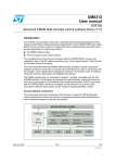
Figure 1 shows the architecture of the firmware. It uses the STM32F103xx standard library
extensively but it also acts directly on hardware peripherals when optimizations in terms of
execution speed or code size are required.
Figure 1.
Firmware architecture
Application layer
STM32F103xx
standard
library
Speed, flux and
torque PIDs
Speed
feedback
Current
feedback
FOC drive
User
interface
SVPWM
STM32F103xx motor control library
STM32F103xx peripherals
ai14812
January 2008
Rev 1
1/121
www.st.com
Contents
UM0492
Contents
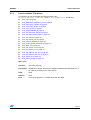
1
Getting started with tools . . . . . . . . . . . . . . . . . . . . . . . . . . . . . . . . . . . . 10
1.1
Working environment . . . . . . . . . . . . . . . . . . . . . . . . . . . . . . . . . . . . . . . . 10
1.2
Software tools . . . . . . . . . . . . . . . . . . . . . . . . . . . . . . . . . . . . . . . . . . . . . . 10
1.3
Library source code . . . . . . . . . . . . . . . . . . . . . . . . . . . . . . . . . . . . . . . . . 11
1.4
2
1.3.2
File structure . . . . . . . . . . . . . . . . . . . . . . . . . . . . . . . . . . . . . . . . . . . . . 11
1.3.3
Starting the IAR toolchain . . . . . . . . . . . . . . . . . . . . . . . . . . . . . . . . . . . 11
Customizing the workspace for your STM32F103xx derivative . . . . . . . . 12
1.4.1
Inkarm_xxx.xcl file (internal Flash or RAM based project) . . . . . . . 12
1.4.2
Extended linker file setting . . . . . . . . . . . . . . . . . . . . . . . . . . . . . . . . . . . 13
Introduction to the PM synchronous motor FOC drive . . . . . . . . . . . . . . . 14
2.1.1
PM motor structures . . . . . . . . . . . . . . . . . . . . . . . . . . . . . . . . . . . . . . . 16
2.1.2
PMSM field oriented control (FOC) fundamental equations . . . . . . . . . 17
2.2
Introduction to sensorless rotor position / speed feedback . . . . . . . . . . . 18
2.3
Introduction to flux weakening control . . . . . . . . . . . . . . . . . . . . . . . . . . . 20
Running the demo program . . . . . . . . . . . . . . . . . . . . . . . . . . . . . . . . . . 22
3.1
Torque control mode . . . . . . . . . . . . . . . . . . . . . . . . . . . . . . . . . . . . . . . . . 22
3.2
Speed control mode . . . . . . . . . . . . . . . . . . . . . . . . . . . . . . . . . . . . . . . . . 24
3.3
Currents and speed regulator tuning . . . . . . . . . . . . . . . . . . . . . . . . . . . . 25
3.4
Observer and PLL gain tuning . . . . . . . . . . . . . . . . . . . . . . . . . . . . . . . . . 27
3.5
DAC functionality . . . . . . . . . . . . . . . . . . . . . . . . . . . . . . . . . . . . . . . . . . . 27
3.6
Power stage feedbacks . . . . . . . . . . . . . . . . . . . . . . . . . . . . . . . . . . . . . . 28
3.7
Fault messages . . . . . . . . . . . . . . . . . . . . . . . . . . . . . . . . . . . . . . . . . . . . 28
3.8
2/121
Download . . . . . . . . . . . . . . . . . . . . . . . . . . . . . . . . . . . . . . . . . . . . . . . . 11
Introduction to the sensorless FOC of PM motors . . . . . . . . . . . . . . . 14
2.1
3
1.3.1
3.7.1
Overcurrent . . . . . . . . . . . . . . . . . . . . . . . . . . . . . . . . . . . . . . . . . . . . . . 29
3.7.2
Overheating . . . . . . . . . . . . . . . . . . . . . . . . . . . . . . . . . . . . . . . . . . . . . . 29
3.7.3
Bus overvoltage . . . . . . . . . . . . . . . . . . . . . . . . . . . . . . . . . . . . . . . . . . . 29
3.7.4
Bus undervoltage . . . . . . . . . . . . . . . . . . . . . . . . . . . . . . . . . . . . . . . . . . 30
3.7.5
Startup failed . . . . . . . . . . . . . . . . . . . . . . . . . . . . . . . . . . . . . . . . . . . . . 30
3.7.6
Error on speed fdbck . . . . . . . . . . . . . . . . . . . . . . . . . . . . . . . . . . . . . . . 30
Setting up the system when using ICS sensors . . . . . . . . . . . . . . . . . . . . 31
UM0492
Contents
3.8.1
3.9
Setting up the system when using an encoder . . . . . . . . . . . . . . . . . . . . . 32
3.10
Setting up the system when using Hall-effect sensors . . . . . . . . . . . . . . . 33
3.11
Progressive sensorless system development . . . . . . . . . . . . . . . . . . . . . 35
3.12
Setting up the system when using a brake resistor . . . . . . . . . . . . . . . . . 36
3.13
4
3.12.1
How to configure the FOC software library for brake resistor
management . . . . . . . . . . . . . . . . . . . . . . . . . . . . . . . . . . . . . . . . . . . . . 37
3.12.2
How to modify the MB459 board for brake resistor management . . . . . 37
Note on debugging tools . . . . . . . . . . . . . . . . . . . . . . . . . . . . . . . . . . . . . 37
Getting started with the library . . . . . . . . . . . . . . . . . . . . . . . . . . . . . . . 39
4.1
Library configuration file: stm32f10x_MCconf.h . . . . . . . . . . . . . . . . . 39
4.2
Drive control parameters: MC_Control_Param.h . . . . . . . . . . . . . . . . . 41
4.3
Incremental encoder parameters: MC_encoder_param.h . . . . . . . . . . . 44
4.4
Hall sensor parameters: MC_hall_prm.h . . . . . . . . . . . . . . . . . . . . . . . 46
4.5
State observer parameters: MC_State_Observer_param.h . . . . . . . . 47
4.6
5
Selecting PHASE_A_ADC_CHANNEL and
PHASE_B_ADC_CHANNEL . . . . . . . . . . . . . . . . . . . . . . . . . . . . . . . . . 31
4.5.1
State observer parameters . . . . . . . . . . . . . . . . . . . . . . . . . . . . . . . . . . 47
4.5.2
Startup parameters . . . . . . . . . . . . . . . . . . . . . . . . . . . . . . . . . . . . . . . . 48
4.5.3
Statistics parameters . . . . . . . . . . . . . . . . . . . . . . . . . . . . . . . . . . . . . . . 50
Permanent-magnet synchronous motor parameters:
MC_PMSM_motor_param.h 50
4.6.1
Basic motor parameters . . . . . . . . . . . . . . . . . . . . . . . . . . . . . . . . . . . . . 50
4.6.2
Motor parameters for sensorless FOC . . . . . . . . . . . . . . . . . . . . . . . . . . 51
4.6.3
Additional parameters for flux weakening operation . . . . . . . . . . . . . . . 51
Library functions . . . . . . . . . . . . . . . . . . . . . . . . . . . . . . . . . . . . . . . . . . . 53
5.1
5.2
Current reading in three shunt resistor topology and space
vector PWM generation: stm32f10x_svpwm_3shunt module . . . . . . . 53
5.1.1
List of available functions . . . . . . . . . . . . . . . . . . . . . . . . . . . . . . . . . . . . 53
5.1.2
Space vector PWM implementation . . . . . . . . . . . . . . . . . . . . . . . . . . . . 57
5.1.3
Current sampling in three shunt topology and general purpose A/D
conversions . . . . . . . . . . . . . . . . . . . . . . . . . . . . . . . . . . . . . . . . . . . . . . 58
5.1.4
Tuning delay parameters and sampling stator currents in three shunt
resistor topology 60
Isolated current sensor reading and space vector PWM
generation: stm32f10x_svpwm_ics module . . . . . . . . . . . . . . . . . . . 64
5.2.1
List of available functions and interrupt service routines . . . . . . . . . . . . 65
3/121
Contents
UM0492
5.2.2
5.3
PMSM field-oriented control: MC_FOC_Drive module . . . . . . . . . . . . . . 68
5.3.1
5.4
5.5
5.7
5.4.1
List of available C functions . . . . . . . . . . . . . . . . . . . . . . . . . . . . . . . . . . 71
5.4.2
Detailed explanation about reference frame transformations . . . . . . . . 75
5.4.3
Circle limitation . . . . . . . . . . . . . . . . . . . . . . . . . . . . . . . . . . . . . . . . . . . 76
Encoder feedback processing: stm32f10x_encoder module . . . . . . . . 78
5.9
5.6.1
List of available functions . . . . . . . . . . . . . . . . . . . . . . . . . . . . . . . . . . . . 81
5.6.2
Speed measurement implementation . . . . . . . . . . . . . . . . . . . . . . . . . . 85
5.6.3
Electrical angle extrapolation implementation . . . . . . . . . . . . . . . . . . . . 87
Sensorless speed / position detection: MC_State_Observer
and MC_State_Observer_Interface modules . . . . . . . . . . . . . . . . . 88
5.8.1
List of available functions . . . . . . . . . . . . . . . . . . . . . . . . . . . . . . . . . . . . 94
5.8.2
PID regulator theoretical background . . . . . . . . . . . . . . . . . . . . . . . . . . 97
5.8.3
Regulator sampling time setting . . . . . . . . . . . . . . . . . . . . . . . . . . . . . . 97
5.8.4
Adjusting speed regulation loop Ki, Kp and Kd vs. motor frequency . . . 98
General purpose time base: stm32f10x_Timebase module . . . . . . . 100
List of available functions and interrupt service routines . . . . . . . . . . . 100
Power stage check-up: MC_MotorControl_Layer module . . . . . . . . 103
5.10.1
5.11
List of available C functions . . . . . . . . . . . . . . . . . . . . . . . . . . . . . . . . . . 89
Currents and speed regulators: MC_PID_regulators module . . . . . . . 94
5.9.1
5.10
List of available functions and interrupt service routines . . . . . . . . . . . . 78
Hall sensor feedback processing: stm32f10x_hall module . . . . . . . . 81
5.7.1
5.8
List of available C functions . . . . . . . . . . . . . . . . . . . . . . . . . . . . . . . . . . 68
Reference frame transformations: MC_Clarke_Park module . . . . . . . . 70
5.5.1
5.6
Current sampling in isolated current sensor topology and integrating
general-purpose A/D conversions . . . . . . . . . . . . . . . . . . . . . . . . . . . . . 67
List of available functions . . . . . . . . . . . . . . . . . . . . . . . . . . . . . . . . . . . 103
Main interrupt service routines: stm32f10x_it module . . . . . . . . . . . 107
5.11.1
List of non-empty interrupt service routines . . . . . . . . . . . . . . . . . . . . . 108
Appendix A Additional information. . . . . . . . . . . . . . . . . . . . . . . . . . . . . . . . . . . 110
4/121
A.1
Adjusting CPU load related to FOC algorithm execution . . . . . . . . . . . . 110
A.2
Selecting the update repetition rate based on the PWM
frequency for 3 shunt resistor configuration . . . . . . . . . . . . . . . . . . . . . . 111
A.3
Fixed-point numerical representation . . . . . . . . . . . . . . . . . . . . . . . . . . . 112
A.4
A priori determination of flux and torque current PI gains . . . . . . . . . . . . 113
A.5
Current regulators fine tuning . . . . . . . . . . . . . . . . . . . . . . . . . . . . . . . . . 116
UM0492
Contents
A.6
A priori determination of state observer gains. . . . . . . . . . . . . . . . . . . . . 118
A.7
Speed formats . . . . . . . . . . . . . . . . . . . . . . . . . . . . . . . . . . . . . . . . . . . . . 119
A.8
References . . . . . . . . . . . . . . . . . . . . . . . . . . . . . . . . . . . . . . . . . . . . . . . 119
Revision history . . . . . . . . . . . . . . . . . . . . . . . . . . . . . . . . . . . . . . . . . . . . . . . . . . . 120
5/121
List of tables
UM0492
List of tables
Table 1.
Table 2.
Table 3.
Table 4.
Table 5.
6/121
Sector identification . . . . . . . . . . . . . . . . . . . . . . . . . . . . . . . . . . . . . . . . . . . . . . . . . . . . . . 58
PWM frequency vs. maximum duty cycle relationship . . . . . . . . . . . . . . . . . . . . . . . . . . . . 64
PWM frequency vs. maximum duty cycle relationship . . . . . . . . . . . . . . . . . . . . . . . . . . . . 77
System performance when using STM3210B-MCKIT . . . . . . . . . . . . . . . . . . . . . . . . . . . 112
Document revision history . . . . . . . . . . . . . . . . . . . . . . . . . . . . . . . . . . . . . . . . . . . . . . . . 120
UM0492
List of figures
List of figures
Figure 1.
Figure 2.
Figure 3.
Figure 4.
Figure 5.
Figure 6.
Figure 7.
Figure 8.
Figure 9.
Figure 10.
Figure 11.
Figure 12.
Figure 13.
Figure 14.
Figure 15.
Figure 16.
Figure 17.
Figure 18.
Figure 19.
Figure 20.
Figure 21.
Figure 22.
Figure 23.
Figure 24.
Figure 25.
Figure 26.
Figure 27.
Figure 28.
Figure 29.
Figure 30.
Figure 31.
Figure 32.
Figure 33.
Figure 34.
Figure 35.
Figure 36.
Figure 37.
Figure 38.
Figure 39.
Figure 40.
Figure 41.
Figure 42.
Figure 43.
Figure 44.
Figure 45.
Figure 46.
Figure 47.
Figure 48.
Firmware architecture . . . . . . . . . . . . . . . . . . . . . . . . . . . . . . . . . . . . . . . . . . . . . . . . . . . . . . 1
JTAG interface for debugging and programming . . . . . . . . . . . . . . . . . . . . . . . . . . . . . . . . 10
File structure . . . . . . . . . . . . . . . . . . . . . . . . . . . . . . . . . . . . . . . . . . . . . . . . . . . . . . . . . . . . 11
Extended linker file setting . . . . . . . . . . . . . . . . . . . . . . . . . . . . . . . . . . . . . . . . . . . . . . . . . 13
FOC algorithm structure, torque control . . . . . . . . . . . . . . . . . . . . . . . . . . . . . . . . . . . . . . . 15
Speed control loop . . . . . . . . . . . . . . . . . . . . . . . . . . . . . . . . . . . . . . . . . . . . . . . . . . . . . . . 15
Different PM motor constructions . . . . . . . . . . . . . . . . . . . . . . . . . . . . . . . . . . . . . . . . . . . . 16
Assumed PMSM reference frame convention . . . . . . . . . . . . . . . . . . . . . . . . . . . . . . . . . . 18
General sensorless algorithm block diagram . . . . . . . . . . . . . . . . . . . . . . . . . . . . . . . . . . . 19
PMSM back-emfs detected by the sensorless state observer algorithm . . . . . . . . . . . . . . 20
Flux weakening operation trajectory . . . . . . . . . . . . . . . . . . . . . . . . . . . . . . . . . . . . . . . . . . 21
LCD screen for Torque control settings . . . . . . . . . . . . . . . . . . . . . . . . . . . . . . . . . . . . . . . 22
LCD screen for Target Iq settings . . . . . . . . . . . . . . . . . . . . . . . . . . . . . . . . . . . . . . . . . . . . 22
LCD screen for Target Id settings . . . . . . . . . . . . . . . . . . . . . . . . . . . . . . . . . . . . . . . . . . . . 23
Speed control main settings . . . . . . . . . . . . . . . . . . . . . . . . . . . . . . . . . . . . . . . . . . . . . . . . 24
LCD screen for setting Target speed . . . . . . . . . . . . . . . . . . . . . . . . . . . . . . . . . . . . . . . . . 24
LCD screen for setting the P term of torque PID . . . . . . . . . . . . . . . . . . . . . . . . . . . . . . . . 26
LCD screen for setting the P term of flux PID . . . . . . . . . . . . . . . . . . . . . . . . . . . . . . . . . . . 26
LCD screen for setting the P term of the speed PID. . . . . . . . . . . . . . . . . . . . . . . . . . . . . . 26
LCD screen for setting the P term of the flux PID . . . . . . . . . . . . . . . . . . . . . . . . . . . . . . . . 27
LCD screen for setting the P term of the flux PID . . . . . . . . . . . . . . . . . . . . . . . . . . . . . . . . 27
Power stage status . . . . . . . . . . . . . . . . . . . . . . . . . . . . . . . . . . . . . . . . . . . . . . . . . . . . . . . 28
Error message shown in the event of an undervoltage fault. . . . . . . . . . . . . . . . . . . . . . . . 29
ICS hardware connections . . . . . . . . . . . . . . . . . . . . . . . . . . . . . . . . . . . . . . . . . . . . . . . . . 31
Encoder output signals: counter operation . . . . . . . . . . . . . . . . . . . . . . . . . . . . . . . . . . . . . 32
60° and 120° displaced Hall sensor output waveforms . . . . . . . . . . . . . . . . . . . . . . . . . . . 33
Determination of Hall electrical phase shift. . . . . . . . . . . . . . . . . . . . . . . . . . . . . . . . . . . . . 34
Brake resistor circuit . . . . . . . . . . . . . . . . . . . . . . . . . . . . . . . . . . . . . . . . . . . . . . . . . . . . . . 37
DBG_TIM1_STOP bit in TIM1 control register (extract from STM32 reference manual) . . 38
Alignment angle . . . . . . . . . . . . . . . . . . . . . . . . . . . . . . . . . . . . . . . . . . . . . . . . . . . . . . . . . 45
Startup current system frequency and amplitude profile . . . . . . . . . . . . . . . . . . . . . . . . . . 49
Vα and Vβ stator voltage components . . . . . . . . . . . . . . . . . . . . . . . . . . . . . . . . . . . . . . . . 57
SVPWM phase voltages waveforms. . . . . . . . . . . . . . . . . . . . . . . . . . . . . . . . . . . . . . . . . . 57
PWM and ADC synchronization . . . . . . . . . . . . . . . . . . . . . . . . . . . . . . . . . . . . . . . . . . . . . 59
Inverter leg and shunt resistor position . . . . . . . . . . . . . . . . . . . . . . . . . . . . . . . . . . . . . . . . 60
Low side switches gate signals (low modulation indexes) . . . . . . . . . . . . . . . . . . . . . . . . . 61
Low side Phase A duty cycle > DT+TN . . . . . . . . . . . . . . . . . . . . . . . . . . . . . . . . . . . . . . . 62
(DT+TN+TS)/2 < ∆DutyA < DT+TN and ∆DutyAB < DT+TR+TS . . . . . . . . . . . . . . . . . . . . . . 62
∆DutyA < (DT+TN+TS)/2 and ∆DutyA-B>DT+TR+TS . . . . . . . . . . . . . . . . . . . . . . . . . . . . . . 63
∆DutyA<(DT+TN+TS)/2 and ∆DutyA-B<DT+TR+TS . . . . . . . . . . . . . . . . . . . . . . . . . . . . . . . 63
Stator currents sampling in ICS configuration (REP_RATE=1) . . . . . . . . . . . . . . . . . . . . . . 68
Clarke, Park, and reverse Park transformations . . . . . . . . . . . . . . . . . . . . . . . . . . . . . . . . . 71
Radians versus s16 . . . . . . . . . . . . . . . . . . . . . . . . . . . . . . . . . . . . . . . . . . . . . . . . . . . . . . 74
s16 versus sine and cosine . . . . . . . . . . . . . . . . . . . . . . . . . . . . . . . . . . . . . . . . . . . . . . . . 74
Transformation from an abc stationary frame to a rotating frame (q, d) . . . . . . . . . . . . . . . 75
Circle limitation working principle . . . . . . . . . . . . . . . . . . . . . . . . . . . . . . . . . . . . . . . . . . . . 77
Hall sensors, output-state correspondence . . . . . . . . . . . . . . . . . . . . . . . . . . . . . . . . . . . . 85
Hall sensor timer interface prescaler decrease. . . . . . . . . . . . . . . . . . . . . . . . . . . . . . . . . . 86
7/121
List of figures
Figure 49.
Figure 50.
Figure 51.
Figure 52.
Figure 53.
Figure 54.
Figure 55.
Figure 56.
Figure 57.
Figure 58.
Figure 59.
Figure 60.
Figure 61.
Figure 62.
8/121
UM0492
Hall sensor timer interface prescaler increase . . . . . . . . . . . . . . . . . . . . . . . . . . . . . . . . . . 86
TIMx_IRQHandler flowchart . . . . . . . . . . . . . . . . . . . . . . . . . . . . . . . . . . . . . . . . . . . . . . . . 87
Hall sensor output transitions . . . . . . . . . . . . . . . . . . . . . . . . . . . . . . . . . . . . . . . . . . . . . . . 88
PID general equation . . . . . . . . . . . . . . . . . . . . . . . . . . . . . . . . . . . . . . . . . . . . . . . . . . . . . 97
Time domain to discrete PID equations . . . . . . . . . . . . . . . . . . . . . . . . . . . . . . . . . . . . . . . 98
Linear curve for coefficient computation . . . . . . . . . . . . . . . . . . . . . . . . . . . . . . . . . . . . . . . 99
AD conversions for three shunt topology stator currents reading and
FOC algorithm execution when REP_RATE=3 and PWM frequency>18 kHz . . . . . . . . 110
AD conversions for three shunt topology stator currents reading and
FOC algorithm execution . . . . . . . . . . . . . . . . . . . . . . . . . . . . . . . . . . . . . . . . . . . . . . . . . 111
Block diagram of PI controller . . . . . . . . . . . . . . . . . . . . . . . . . . . . . . . . . . . . . . . . . . . . . . 113
Closed loop block diagram . . . . . . . . . . . . . . . . . . . . . . . . . . . . . . . . . . . . . . . . . . . . . . . . 114
Pole-zero cancellation . . . . . . . . . . . . . . . . . . . . . . . . . . . . . . . . . . . . . . . . . . . . . . . . . . . 114
Block diagram of closed loop system after pole-zero cancellation . . . . . . . . . . . . . . . . . . 115
KP = 8000 and KI = 2000 . . . . . . . . . . . . . . . . . . . . . . . . . . . . . . . . . . . . . . . . . . . . . . . . . 117
KP = 8000 and KI = 1000 . . . . . . . . . . . . . . . . . . . . . . . . . . . . . . . . . . . . . . . . . . . . . . . . . 118
UM0492
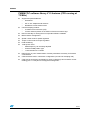
PMSM FOC software library V1.0 features (CPU running at
72 MHz)
●
●
Supported speed feedbacks:
–
Sensorless
–
60° or 120° displaced Hall sensors
–
Quadrature incremental encoder
Current-sampling method:
–
2 isolated current sensors (ICS)
–
3 shunt resistors placed on the bottom of the three inverter lags
●
DAC functionality for tracing the most important software variables
●
Brake resistor management
●
Speed control mode for speed regulation
●
Torque control mode for torque regulation
●
Field weakening
●
16-bit space vector
–
PWM frequency can be easily adjusted
–
Centered PWM pattern type
–
11-bit resolution at 17.6 kHz
●
Rules for the “a priori” determination of all the parameters necessary for firmware
customization
●
CPU load below 25% in sensorless configuration (10 kHz FOC sampling rate)
●
Code size in sensorless configuration is about 13 Kbytes (3-shunt-resistor current
reading) plus 11.7 Kbytes for LCD/joystick management
9/121
Getting started with tools
1
UM0492
Getting started with tools
To develop an application for a PM synchronous motor using the PMSM FOC software
library, you must set up a complete development environment, as described in the following
sections. A PC running Windows XP is necessary.
1.1
Working environment
The PMSM FOC software library was fully validated using the main hardware boards
included in STM3210B-MCKIT starter kit (a complete inverter and control board). The
STM3210B-MCKIT starter kit provides an ideal toolset for starting a project and using the
library. Therefore, for rapid implementation and evaluation of the software described in this
user manual, it is recommended to acquire this starter kit.
It is also recommended to install the IAR EWARM C toolchain version 4.42, which was used
to compile the PMSM FOC software library. With this toolchain, you do not need to
configure your workspace. You can set up your workspace manually for any other toolchain.
A free ‘kickstart edition’ of the IAR EWARM C toolchain with a 32Kb limitation can be
downloaded from www.iar.com; it is sufficient to compile and evaluate the software library
presented here.
1.2
Software tools
A complete software package consists of:
●
A third-party integrated development environment (IDE)
●
A third-party C-compiler
This library was compiled using the third-party IAR C toolchain.
●
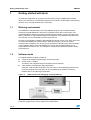
JTAG interface for debugging and programming
Using the JTAG interface of the MCU you can enter in-circuit debugging session with
most of toolchains. Each toolchain can be provided with an interface connected
between the PC and the target application.
Figure 2.
JTAG interface for debugging and programming
The JTAG interface can also be used for in-circuit programming of the MCU. Other
production programmers can be obtained from third-parties.
10/121
UM0492
Getting started with tools
1.3
Library source code
1.3.1
Download
The complete source files are available for free download on the ST website
(www.stmcu.com), in the Technical Literature and Support Files section, as a zip file.
Note:
It is highly recommended to check for the latest releases of the library before starting any
new development, and then to verify from time to time all release notes to be aware of any
new features that might be of interest for your project. Registration mechanisms are
available on ST web sites to automatically obtain updates.
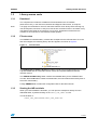
1.3.2
File structure
The PMSM FOC software library contains the workspace for the IAR toolchain. Once the
files are unzipped, the following library structure appears, as shown in Figure 3.
Figure 3.
File structure
The STM32 FOC Firmware Libraries v1.0 folder contains the firmware libraries for running
3-phase PMSM and AC sensored induction motors and 3-phase PMSM sensorless
induction motors.
The STM32F10xFWLib Vx.y folder contains the standard library for the STM32F103xx.
The inc, src and lib folders contain the header files, the source files and the library files of
the motor control library.
Finally, EWARM folder contains the configuration files for the IAR toolchain.
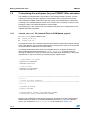
1.3.3
Starting the IAR toolchain
When you have installed the toolchain, you can open the workspace directly from the
dedicated folder, by double-clicking on the STM32_FOC_PMSM.eww file:
The file location is:
\STM32_FOC_PMSM\EWARM\STM32_FOC_PMSM.eww
11/121
Getting started with tools
1.4
UM0492
Customizing the workspace for your STM32F103xx derivative
The PMSM FOC software library was written for the STM32F103VB6. However, it works
equally successfully with all the products in the STM32F103xx performance line family.
Using a different STM32F103xx sales type may require some modifications to the library,
according to the available features (some of the I/O ports are not present on low-pin count
packages). Refer to the MCU datasheet for further details.
Also, depending on the memory size, the workspace may have to be configured to fit your
STM32F103xx MCU derivative.
1.4.1
Inkarm_xxx.xcl file (internal Flash or RAM based project)
The IAR\config folder contains 3 files:
●
Inkarm_flash.xcl
●
Inkarm_ram.xcl
These files are used as an extended command linker file and contain linker options. Memory
areas, start address, size, and other parameters are declared here. Refer to the Cortex-M3
Technical Reference Manual for more information.
The default extended linker file used in the standard library to configure the device for
internal Flash-based resident firmware is Inkarm_flash.xcl. An extract of this file
showing the definitions of heap and stack size is provided below. Depending on the project
requirements, it may be necessary to manually edit the segment sizes.
...
// Code memory in FLASH
-DROMSTART=0x8000000
-DROMEND=0x801FFFF
// Data in RAM
-DRAMSTART=0x20000000
-DRAMEND=0x20004FFF
...
//*****************************************************************
********
// Stack and heap segments.
//*****************************************************************
********
-D_CSTACK_SIZE=800
-D_HEAP_SIZE=400
-Z(DATA)CSTACK+_CSTACK_SIZE=RAMSTART-RAMEND
-Z(DATA)HEAP+_HEAP_SIZE=RAMSTART-RAMEND
Memory size modifications might also be necessary according to the MCU specifications.
Default settings are done for a 128 KB embedded Flash memory. If you use a different
device, you must edit the Inkarm_flash.xcl file as explained in Section 1.4.2.
12/121
UM0492
1.4.2
Getting started with tools
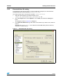
Extended linker file setting
As mentioned in the previous section, in the provided IAR workspace, the internal Flash
extended linker file is set by default (Inkarm_flash.xcl).
To modify the linker file to be used (for example, Inkarm_ram.xcl):
1.
Open the IAR workspace by double-clicking on the
\STM32_FOC_PMSM\EWARM\STM32_FOC_PMSM.eww file.
2.
Go to the Project menu, select Options... then Linker, and select the Config submenu.
The dialog box shown in Figure 4 is displayed.
3.
In the Override default field, type the name of the linker file you want to use, and then
click OK.
Selecting the Inkarm_ram.xcl file makes the IAR XLINK linker place the memory
segments on RAM memory.
Figure 4.
Extended linker file setting
13/121
Introduction to the sensorless FOC of PM motors
UM0492
2
Introduction to the sensorless FOC of PM motors
2.1
Introduction to the PM synchronous motor FOC drive
This software library is designed to achieve the high dynamic performance in AC
permanent-magnet synchronous motor (PMSM) control offered by the well-established field
oriented control (FOC) strategy.
With this approach, it can be stated that, by controlling the two currents iqs and ids, which are
mathematical transformations of the stator currents, it is possible to offer electromagnetic
torque (Te) regulation and, to some extent, flux weakening capability.
This resembles the favorable condition of a DC motor, where those roles are held by the
armature and field currents.
Therefore, it is possible to say that FOC consists in controlling and orienting stator currents
in phase and quadrature with the rotor flux; this definition makes clear that a means of
measuring stator currents and the rotor angle is needed.
Basic information on the algorithm structure (and then on the library functions) is
represented in Figure 5.
14/121
●
the space vector PWM block (CALC SVPWM) implements an advanced modulation
method that reduces current harmonics, thus optimizing DC bus exploitation
●
the current reading block allows the system to measure stator currents correctly, using
either cheap shunt resistors or market-available isolated current Hall sensors (ICS)
●
the rotor speed/position feedback block allows the system to handle Hall sensor or
incremental encoder signals in order to correctly acquire the rotor angular velocity or
position. Moreover, this firmware library provides sensorless detection of rotor
speed/position, as described in Section 2.2.
●
the PID-controller blocks implement proportional, integral and derivative feedback
controllers (current regulation)
●
the Clarke, Park, Reverse Park & Circle limitation blocks implement the mathematical
transformations required by FOC
UM0492
Introduction to the sensorless FOC of PM motors
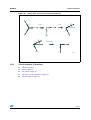
Figure 5.
FOC algorithm structure, torque control
Figure 6.
Speed control loop
The iqs and ids current components can be selected to perform electromagnetic torque and
flux control.
On the other hand, they can be driven to implement a speed control loop (as depicted in
Figure 6, via the torque and flux controller block, which implements a PID controller for
speed regulation, and a flux weakening strategy). In that case also, a means of detecting
rotor speed is needed.
15/121
Introduction to the sensorless FOC of PM motors
2.1.1
UM0492
PM motor structures
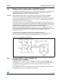
Mainly, there are two different PM motor constructions available:
a)
In the first one, drawing a) in Figure 7, the magnets are glued to the surface of the
rotor, and this is the reason why it is referred to as SM-PMSM (surface mounted
PMSM)
b)
in the second one, illustrated by drawings b) and c) in Figure 7, the magnets are
embedded in the rotor structure. This construction is known as IPMSM (interior
PMSM)
Figure 7.
Different PM motor constructions
SM-PMSMs inherently have an isotropic structure, that is, the direct and quadrature
inductances Ld and Lq are the same. Usually, their mechanical structure allows a wider
airgap, which in turn means lower flux weakening capability, thus setting a limit to the
maximum speed.
On the other hand, IPMSMs show an anisotropic structure, slight in the b) construction
(called inset PM motor), strong in the c) configuration (called buried or radial PM motor);
their fine mechanical structure usually shows a narrow airgap, thus giving good flux
weakening capability.
This firmware library is optimized for use in conjunction with SM-PMSMs and, to some
extent, with inset PM machines.
16/121
UM0492
2.1.2
Introduction to the sensorless FOC of PM motors
PMSM field oriented control (FOC) fundamental equations
With reference to Figure 8, the motor voltage and flux linkage equations of an SM-PMSM
are generally expressed as:
dλ abc
ν abc = r s i abc + -----------------s
s
s
dt
L ms
– --------2
L ls + L ms
L ms
– --------2
L ms
– --------2
L ms
– --------2
L ls + L ms
L ls + L ms
λ abc =
s
L ms
– --------2
L ms
– --------2
sin θ r
i abc +
s
sin ⎛ θ r – 2π
------⎞
⎝
3 ⎠ Φm , where:
2π⎞
sin ⎛ θ r + -----⎝
3⎠
●
rs is the stator phase winding resistance
●
Lls is the stator phase winding leakage inductance
●
Lms is the stator phase winding magnetizing inductance
●
θr is the rotor electrical angle
●
Φm is the flux linkage due to permanent magnets
The complexity of these equations is apparent, as the three stator flux linkages are mutually
coupled and, what is more, as they are dependent on the rotor position, which is timevarying and a function of the electromagnetic and load torques.
The reference frame theory simplifies the PM motor equations, by making a change of
variables that refers the stator quantities abc (that can be visualized as directed along axes
each 120° apart) to qd components, directed along a 90° apart axes, rotating synchronously
with the rotor, and vice versa (see Section 5.4 for more details). The d “direct” axis is aligned
with the rotor flux, while the q “quadrature” axis leads at 90 degrees in the positive rolling
direction.
The motor voltage and flux equations are simplified to:
λ q = Ls iq
s
s
λ d = L s i d + Φm
{
s
s
dλ q
ν q = r s i q + -----------s + ωr λ d , where: Ls = Lls + 3/2 Lms
s
s
s
dt
dλ d
ν d = r s i d + -----------s + ωr λ q
s
s
s
dt
{
The electromagnetic torque equation becomes:
3
3
T e = --- p ( λ ds i qs – λ qs i ds ) = --- p ( L s i ds i qs + Φm i qs – L s i qs i d )
s
2
2
3
T e = --- p ( Φm i qs )
2
The last equation makes it clear that the quadrature current component iqs has linear control
on the torque generation, whereas the current component ids has no effect on it (as
mentioned above, these equations are valid for SM-PMSMs).
17/121
Introduction to the sensorless FOC of PM motors
UM0492
Therefore, if Is is the motor rated current, then its maximum torque is produced for iqs = Is
2
2
and ids = 0 (in fact I s = i qs + i ds ).
On the other hand, the magnetic flux can be weakened by acting on the direct axis current
ids; this extends the achievable speed range, but at the cost of a decrease in quadrature
current iqs, and hence in the electromagnetic torque supplied to the load (see Section 2.3 for
details about the Flux weakening strategy).
In conclusion, by regulating the motor currents through their components iqs and ids, FOC
manages to regulate the PMSM torque and flux; current regulation is achieved by means of
what is usually called a “synchronous frame CR-PWM”.
Figure 8.
2.2
Assumed PMSM reference frame convention
Introduction to sensorless rotor position / speed feedback
In Section 2.1 it has been shown that rotor position / speed measurement has a crucial role
in PMSM field oriented control. Hall sensors or encoders are broadly used in the control
chain for that purpose.
Sensorless algorithms for rotor position / speed feedback are considered very useful and for
different reasons: to lower the overall cost of the application, to enhance the reliability by
redundancy, etc.
This firmware library provides a complete solution for sensorless detection of rotor position /
speed feedback, which is based on the state observer theory.
A state observer, in control theory, is a system that provides an estimation of the internal
state of a real system, given its input and output measurement.
In our case, the internal states of the motor are the back-emfs and the phase currents, while
the input and output quantities supplied are the phase voltages and measured currents,
respectively (see Figure 9).
DC bus voltage measurement is used to convert voltage commands into voltage applied to
motor phases.
18/121
UM0492
Introduction to the sensorless FOC of PM motors
Figure 9.
General sensorless algorithm block diagram
In particular, the observed states are compared for consistency with the real system via the
phase currents, and the result is used to adjust the model through a gain vector (K1, K2).
The motor back-emfs are defined as:
e α = Φm pωr cos ( pωr t )
e β = – Φm pωr sin ( pωr t )
As can be seen, they hold information about the rotor angle. Then, back-emfs are fed to a
block which, acting as a PLL, is able to reconstruct the rotor electrical angle and speed.
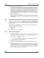
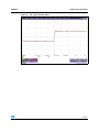
Figure 10 shows a scope capture taken while the motor is running in field oriented control
(positive rolling direction); the yellow and the red waveforms (C1,C2) are respectively the
observed back-emfs alpha and beta, the blue square wave (C3) is a signal coming from a
Hall sensor cell placed on the a-axis, the green sinewave is current ia (C4).
19/121
Introduction to the sensorless FOC of PM motors
UM0492
Figure 10. PMSM back-emfs detected by the sensorless state observer algorithm
More information on how to set parameters to make the firmware suit the user’s motor could
be found in Section 4.5.
2.3
Introduction to flux weakening control
The purpose of the flux weakening functionality is to expand the operating limits of a
permanent-magnet motor by reaching speeds higher than rated, as many applications
require under operating conditions where the load is lower than rated. Here, the rated speed
is considered to be the highest speed at which the motor can still deliver maximum torque.
The magnetic flux can be weakened by acting on the direct axis current id; given a motor
2
2
rated current In, such that I n = i q + i d , if we choose to set id ≠ 0, then the maximum
available quadrature current iq is reduced (consequently, in case of SM-PMSM as shown in
Section 2.1.2) the maximum deliverable electromagnetic torque is also reduced.
To optimize the efficiency of the operations, theimplemented flux weakening strategy aims at
driving the motor along a maximum-torque-per-ampere current vector trajectory (see [3] in
Appendix A.8: References).
20/121
UM0492
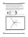
Introduction to the sensorless FOC of PM motors
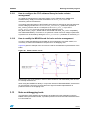
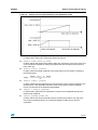
Figure 11. Flux weakening operation trajectory
With reference to Figure 11, it is possible to state that the motor thermal rating and power
converter capability define a “current-limit” circle (every current vector inside this circle is
allowed on a thermal basis). On the other hand, the DC bus voltage, motor parameters and
electrical frequency ω define a “voltage-limit” circle (every current vector inside this circle
could exist on an electrical basis). Therefore, for each frequency ω, and hence for each rotor
speed, the current vectors allowed are those that belong to the intersection of the currentlimit circle and the specific voltage-limit circle.
Each rotor speed determines a pair (id, iq max) = f(ω); the whole set of pairs draws the
trajectory of flux-weakening operations. With reference to Figure 11, it is possible to
recognize ω1 as the motor rated speed and the red curve as the flux-weakening and
maximum-torque-per-ampere trajectory.
By providing motor parameters (see PMSM_Flux_Weakening.xls spreadsheet included in
CD-ROM), it is possible to precalculate the aforementioned current vector trajectory and
insert the result in the proper parameter header file of the firmware library (see Section 4.6).
21/121
Running the demo program
3
Running the demo program
3.1
Torque control mode
UM0492
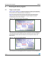
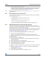
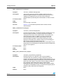
Figure 12, Figure 13 and Figure 14 show a few LCD menus for setting control parameters
when in Torque Control mode. The parameter highlighted in red color is the one that can be
set and its value can be modified by acting on the joystick key.
Moving the joystick up/down selects the active control mode (in the example shown in
Figure 12, it is Torque control). Once the motor Start command has been issued (by
pressing the JOY or KEY key), this parameter is no longer accessible. It becomes
accessible again when the motor is stopped.
Figure 12. LCD screen for Torque control settings
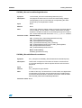
From the previous screen (Figure 12), if the joystick is moved to the right, the Target Iq
current component becomes highlighted (in red). This parameter can now be modified by
moving the joystick up/down. Once the motor Start command has been issued, Target Iq
can be changed in runtime while the measured Iq current component is shown in the
Measured field.
Figure 13. LCD screen for Target Iq settings
From the previous screen (Figure 13), if the joystick is moved to the right, the Target Id
current component becomes highlighted (in red). This parameter can now be modified by
22/121
UM0492
Running the demo program
moving the joystick up/down. Once the motor Start command has been issued, the Target Id
can be changed in runtime while the measured Id current component is shown in the
Measured field.
Figure 14. LCD screen for Target Id settings
The motor is stopped (main state machine moves from Run to Stop state) by pressing either
the KEY button or the joystick.
Different motor ramp-up strategies are used in torque control mode depending on the kind of
configuration utilized for the speed / position feedback:
●
ENCODER or VIEW_ENCODER_FEEDBACK uncommented in the configuration file
stm32f10x_MCconf.h. In this case a rotor pre-positioning phase (also called alignment)
is necessary in order to make absolute the otherwise relative position information fed
back by the quadrature encoder. This alignment phase is performed only at first startup
after any detected microcontroller fault event or reset. Refer to Section 4.3 for a deeper
description of this procedure.
After the rotor pre-positioning is performed, if ENCODER is uncommented, the variables
containing the target value of the Iq and Id stator current components (respectively
PID_Torque_InitStructure.Reference and
PID_Flux_InitStructure.Reference) are initialized with the values
PID_TORQUE_REFERENCE and PID_FLUX_REFERENCE defined in the header file
MC_Control_Param.h; the main state machine switches from the Start to the Run state.
On the other hand, if VIEW_ENCODER_FEEDBACK is uncommented, the ramp-up
strategy related to the sensorless operation starts just after the end of the prepositioning.
●
HALL_SENSORS is uncommented in the stm32f10x_MCconf.h configuration file. In this
case no rotor pre-positioning is performed and the
PID_Torque_InitStructure.Reference software variable is simply initialized
with the PID_TORQUE_REFERENCE value defined in the MC_Control_Param.h header
file. The software variable containing the electrical rotor angle is initialized based on the
digital value of the three Hall sensor outputs, and the main state machine switches from
the Start to the Run state.
●
NO_SPEED_SENSORS is uncommented in stm32f10x_MCconf.h. In case of sensorless
motor driving, a particular ramp-up is necessary in order to make the rotor move and
the sensorless algorithm converge to the actual rotor position. A deeper description of
the ramp-up procedure is described in Section 4.5.
23/121
Running the demo program
3.2
UM0492
Speed control mode
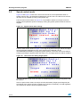
Figure 15 and Figure 16 show two LCD menus used to set control parameters when in
Speed control mode. The parameter highlighted in red color is the one that can be set and
its value can be modified by acting on the joystick key.
From the menu screen shown in Figure 15, it is possible to switch from Torque control to
Speed control operations (and vice versa) by moving the joystick up/down while the motor is
stopped.
Figure 15. Speed control main settings
From the menu screen shown in Figure 16, moving the joystick to the right selects the Target
speed (parameter highlighted in red). Once selected, the parameter can be
incremented/decremented by moving the joystick up/down. The motor can then be started
simply by pressing the joystick. When the motor is on, the target speed can still be modified.
Figure 16. LCD screen for setting Target speed
Like in the torque control mode, the motor is started/stopped by pressing the joystick or the
KEY button.
Since in speed control mode, the torque and flux parameters (Target Iq and Target Id) are
the outputs of the Torque and flux controller, they cannot be set directly. The PID regulators
can however be real-time tuned as explained below.
24/121
UM0492
Running the demo program
Different motor ramp-up strategies are used in speed control mode depending on the kind of
configuration utilized for the speed / position feedback:
●
ENCODER or VIEW_ENCODER_FEEDBACK uncommented in the stm32f10x_MCconf.h
configuration file. As already stated in the previous paragraph, a rotor pre-positioning
phase (also called alignment) is necessary in this case. Refer to Section 4.3 for a
deeper description of this procedure.
After the rotor pre-positioning is performed, if ENCODER is uncommented the variables
containing the target values of the Iq and Id current components
(PID_Torque_InitStructure.Reference and PID_Flux_InitStructure.Reference,
respectively) are driven by the torque and flux controller block and the main state
machine switches from the Start to the Run state. On the other hand, if
VIEW_ENCODER_FEEDBACK is uncommented, the ramp-up strategy related to the
sensorless operation starts just after the end of the pre-positioning.
3.3
●
HALL_SENSORS is uncommented in the stm32f10x_MCconf.h configuration file. The
PID_Torque_InitStructure.Reference software variable is driven by the flux and torque
controller block from the moment the start command is given. The software variable
containing the electrical rotor angle is also initialized based on the digital value of the
three Hall sensor outputs at that moment. Finally, the main state machine switches
from the Start to the Run state.
●
NO_SPEED_SENSORS is uncommented in stm32f10x_MCconf.h. In case of sensorless
motor driving, a particular ramp-up is necessary in order to make the rotor move and
the sensorless algorithm converge to the actual rotor position. A more detailed
description of the ramp-up procedure is described in Section 4.5.
Currents and speed regulator tuning
As already exposed in Section 2.1, the Iq and Id currents regulation is achieved by mean of
two PID controllers where the derivative action can be optionally disabled by uncommenting
the definition of Id_Iq_DIFFERENTIAL_TERM_ENABLED in stm32f10x_MCconf.h. Next
figures show the two LCD menus allowing the real-time tuning of the proportional, integral
and in case it is present derivative gains:
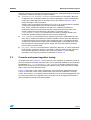
Figure 17 shows the screen used to select either of the torque PID coefficients whereas
Figure 18 shows the screen used to select either of the flux PID coefficients. From both
screen, either of the P, I or D (when present) coefficient can be selected (highlighted in red)
by moving the joystick to the right/left. Then, each value can be changed (incremented or
decremented) by pressing the joystick up/down.
25/121
Running the demo program
UM0492
Figure 17. LCD screen for setting the P term of torque PID
Figure 18. LCD screen for setting the P term of flux PID
Moreover, to achieve speed regulation in speed control mode, a PI(D) is also implemented
inside the torque and flux controller block. The tuning of its related gains can be done in real
time by means of the dedicated LCD menu:
Figure 19. LCD screen for setting the P term of the speed PID
Like for the previous menus, either of the P, I or D (when present) coefficients can be
selected (highlighted in red) by moving the joystick to the right/left. The desired values can
then be changed (incremented or decremented) by pressing the joystick up/down.
26/121
UM0492
3.4
Running the demo program
Observer and PLL gain tuning
In the default configuration of the firmware library, the tuning of the sensorless algorithm is
disabled. Nevertheless, when the OBSERVER_GAIN_TUNING definition is not commented in
the stm32F10x_MCconf.h configuration header file, a dedicated menu is shown on the LCD.
Figure 20. LCD screen for setting the P term of the flux PID
When the menu shown in Figure 20 is displayed, the joystick can be moved to the right/left
to navigate between the different gains. Pressing the joystick up/down will
increment/decrement the gain highlighted in red color.
This menu is used to change both the observer and the PLL gains in real time. This feature
is particularly useful when used in conjunction with the DAC functionality and with a
firmware configuration handling either Hall effect sensors or an encoder. In this way, it is
possible to modify the observer and PLL gains by looking for example at both the observed
and measured rotor electrical angle and by adjusting the gains so as to cancel any error
between the two waveforms.
3.5
DAC functionality
When enabled in the stm32F10x_MCconf.h, the DAC functionality is a powerful debug tool
which allows the simultaneous tracing of up to two software variables selectable in real time
using a dedicated menu.
Figure 21. LCD screen for setting the P term of the flux PID
27/121
Running the demo program
UM0492
When the menu shown in Figure 21 is displayed, the joystick can be moved to the right/left
to select the desired microcontroller pin. To change the software variable in output, move the
joystick up/down (the list of the available variables depends on the selected firmware
configuration). For all other menus, pressing the joystick or the Key button will cause the
motor to start/stop.
The DAC functionality was implemented in the presented firmware library by using two out
of the four TIM3 output compare channels (PB0 and PB1 pins) and by modulating the duty
cycle of the generated 30 kHz PWM signal. In order to properly filter the generated signals
without introducing important delays on the waveforms, it is suggested to use a proper firstorder low-pass filter (e.g. with a 10 kΩ resistor and a 22 nF capacitor).
3.6
Power stage feedbacks
A dedicated menu was designed to show the value in volts of the DC bus voltage and the
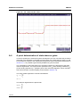
temperature of the STM3210B-MCKIT power board heat sink:
Figure 22. Power stage status
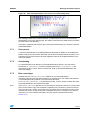
3.7
Fault messages
This section provides a description of all the possible fault messages that can be detected
when using the software library together with the STM3210B-MCKIT. Figure 23 shows a
typical error message as displayed on the LCD.
28/121
UM0492
Running the demo program
Figure 23. Error message shown in the event of an undervoltage fault
The message “Press ‘Key’ to return to menu” is visible only if the source of the fault has
disappeared. In this case, pressing the ‘Key’ button causes the main state machine to switch
from the Fault to the Idle state.
There are six different fault sources when using the firmware library in conjunction with the
STM3210B-MCKIT:
3.7.1
Overcurrent
A low level was detected on the PWM-peripheral-dedicated pin (BKIN). If the STM3210BMCKIT is being used, this means that either the hardware overtemperature protection or the
hardware overcurrent protection has been triggered. Refer to the STM3210B-MCKIT user
manual for details.
3.7.2
Overheating
An overtemperature was detected on the dedicated analog channel. The intervention
threshold (NTC_THRESHOLD_C) and the related hysteresis (NTC_HYSTERESIS_C) are
specified in the MC_Control_Param.h header file. Refer to the STM3210B-MCKIT user
manual for details.
3.7.3
Bus overvoltage
Available only if the BRAKE_RESISTOR definition is commented (default) in
stm32f10x_MCconf.h configuration header file. It means that an overvoltage was detected
on the dedicated analog channel. The intervention threshold
(OVERVOLTAGE_THRESHOLD_V) is specified in the MC_Control_Param.h header file. Refer
to STM3210B-MCKIT user manual for details.
Note:
If the BRAKE_RESISTOR definition is not commented in stm32f10x_MCconf.h, it is assumed
that a resistor with a high power dissipation capability was connected in parallel to the bus
capacitors through a switch. In this case the overvoltage does not generate a FAULT event
because the resistor is supposedly able to dissipate the excess of voltage across the bus
capacitors. For more detailed information on brake resistor management see also
Section 3.12.
29/121
Running the demo program
3.7.4
UM0492
Bus undervoltage
The bus voltage is below 20 V DC. This threshold is specified in the MC_Control_Param.h
header file by the UNDERVOLTAGE_THRESHOLD_V parameter. Refer to STM3210B-MCKIT
user manual for details.
3.7.5
Startup failed
Available only when NO_SPEED_SENSORS is not commended. It signals that no startup
output condition was detected during motor ramp-up (FREQ_START_UP_DURATION in
MC_State_Observer_param.h). See also Section 4.5.2.
3.7.6
Error on speed fdbck
An error on the speed / position feedback was noticed. Depending on the utilized kind of
feedback this could mean that:
30/121
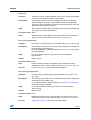
●
if an encoder is being used, the measured speed was out of the allowed range
([MINIMUM_MECHANICAL_SPEED_RPM; MAXIMUM_MECHANICAL_SPEED_RPM]) for a
consecutive number of times equal to or higher than MAXIMUM_ERROR_NUMBER (all
these parameters can be found in MC_encoder_param.h). For instance, this could
mean that the encoder connection was lost. See also Section 4.3.
●
in case of a Hall sensors configuration, the timer utilized for interfacing with the three
Hall effect sensors overflowed for HALL_MAX_OVERFLOWS (MC_hall_param.h)
consecutive times, as mentioned in Section 4.4 and explained in Section 5.6. This
usually indicates that information has been lost (Hall sensor timeout) or that speed is
decreasing very sharply.
●
in case of sensorless operation, the quality of the speed measurement expressed in
terms of the distribution around the mean value is not good. This typically means that
either the observer is not properly tuned or that the speed is so low that a good
observation of the induced B-emf is not possible (e.g. rotor is locked). Refer also to
Section 4.5.3.
UM0492
3.8
Running the demo program
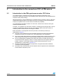
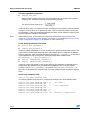
Setting up the system when using ICS sensors
The default configuration provides for the use of three shunt resistors and no speed sensor.
This section gives you information about how to provide the STM32F103xx with ICS
feedback signals and to properly customize the firmware.
Caution:
When using two ICS for stator current reading, you must ensure that the conditioned
sensors output signal range is compatible with the STM32F103xx supply voltage.
In order for the implemented FOC algorithm to work properly, it is necessary to ensure that
the software implementation of the stm32f10x_svpwm_ics module and the hardware
connections of the two ICS are consistent.
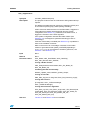
As illustrated in Figure 24, the two ICS must act as transducers on motor phase currents
coming out of the inverter legs driven by STM32F103xx PWM signals PWM1 (Phase A) and
PWM2 (Phase B). In particular, the current coming out of inverter Phase A must be read by
an ICS whose output has to be sent to the analog channel specified by the
PHASE_A_ADC_CHANNEL parameter in MC_pwm_ics_prm.h. Likewise, the current
coming out of inverter Phase B must be read by the other ICS and its output has to be sent
to the analog channel specified by the PHASE_B_ADC_CHANNEL parameter in
MC_pwm_ics_prm.h.
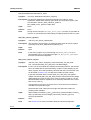
About the positive current direction convention, a positive half-wave on
PHASE_X_ADC_CHANNEL is expected, corresponding to a positive half-wave on the
current coming out of the related inverter leg (see direction of I in Figure 24).
Figure 24. ICS hardware connections
3.8.1
Selecting PHASE_A_ADC_CHANNEL and
PHASE_B_ADC_CHANNEL
Default settings for PHASE_A_ADC_ CHANNEL and PHASE_B_ADC_CHANNEL are
respectively ADC_CHANNEL11 and ADC_CHANNEL12. You can change the default settings if
the hardware requires it by editing the “Current reading parameters” section of the
MC_pwm_ics_prm.h file.
As an example, in order to convert Phase X (X =A, B) current feedback on ADC channel 0,
the related parameters must be edited as shown below:
31/121
Running the demo program
#define PHASE_X_ADC_CHANNEL
#define PHASE_X_GPIO_PORT
#define PHASE_X_GPIO_PIN
3.9
UM0492
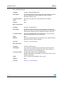
ADC_Channel_0
GPIOA
GPIO_Pin_0
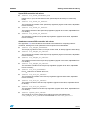
Setting up the system when using an encoder
Quadrature incremental encoders are widely used to read the rotor position of electric
machines.
As the name implies, incremental encoders actually read angular displacements with
respect to an initial position: if that position is known, then the rotor absolute angle is known
too. For this reason it is always necessary, when processing the encoder feedback
(ENCODER or VIEW_ENCODER_FEEDBACK definitions not commented in
stm32f10x_MCconf.h), to perform a rotor prepositioning before the first startup after any
fault event or microcontroller reset.
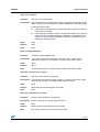
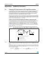
Quadrature encoders have two output signals (represented in Figure 25 as TI1 and TI2).
With these, and with the STM32F103xx standard timer in encoder interface mode, it is
possible to get information about the rolling direction.
Figure 25. Encoder output signals: counter operation
In addition, the rotor angular velocity can be easily calculated as a time derivative of the
angular position.
To set up the PMSM FOC software library for use with an incremental encoder, simply
modify the stm32f10x_MCconf.h and MC_encoder_param.h header files according to
the indications given in Section 4.1 and Section 4.3, respectively.
However, some extra care should be taken, concerning what is considered to be the positive
rolling direction: this software library assumes that the positive rolling direction is the rolling
direction of a machine that is fed with a three-phase system of positive sequence.
Because of this, and because of how the encoder output signals are wired to the
microcontroller input pins, it is possible to have a sign discrepancy between the real rolling
direction and the direction that is read. To avoid this kind of reading error, apply the following
procedure:
32/121
UM0492
Running the demo program
1.
Turn the rotor by hand in the direction assumed to be positive and look at the B-emf
induced on the three motor phases. For this purpose, a neutral point may need to be
reconstructed with three resistors if the real one is not available.
2.
Connect the motor phases to the hardware respecting the positive sequence (for
instance when using the MB459 board, a positive sequence of the motor phases may
be connected to J5 2,1 and 3).
3.
Run the firmware in encoder configuration and turn by hand the rotor in the direction
assumed to be positive. If the measured speed shown on the LCD is positive, the
connection is correct, otherwise, it can be corrected by simply swapping and rewiring
the encoder output signals.
If this is not practical, a software setting may be modified instead: in the
stm32f10x_encoder.c file, replace the code line 164:
TIM_ICPolarity_Rising, TIM_ICPolarity_Rising);
by
TIM_ICPolarity_Rising, TIM_ICPolarity_Falling);
3.10
Setting up the system when using Hall-effect sensors
Hall-effect sensors are devices capable of sensing the polarity of the rotor’s magnetic field;
they provide a logic output, which is 0 or 1 depending on the magnetic pole they face and
thus, on the rotor position.
Typically, in a three-phase PM motor three Hall-effect sensors are used to feed back the
rotor position information. They are usually mechanically displaced by either 120° or 60° and
the presented firmware library was designed to support both possibilities. To set up the
PMSM FOC software library for use with three Hall sensors, simply modify the
stm32f10x_MCconf.h and MC_hall_param.h header files according to the indications given
in Section 4.1 and Section 4.4, respectively.
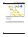
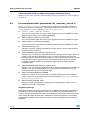
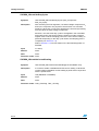
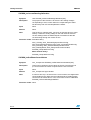
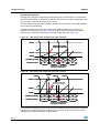
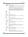
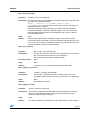
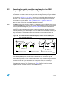
As shown in Figure 26, the typical waveforms can be visualized at the sensor outputs in
case of 60° and 120° displaced Hall sensors. More particularly, Figure 26 refers to an
electrical period (i.e. one mechanical revolution in case of one pole pair motor).
Figure 26. 60° and 120° displaced Hall sensor output waveforms
3 sensors 120˚
3 sensors 60˚
H1
H1
H2
120˚
H2
H1
60˚
H3
H3
H1
H2
H2
H3
H3
ai14826
33/121
Running the demo program
UM0492
Since the rotor position information they provide is absolute, there is no need for any initial
rotor prepositioning. Particular attention must be paid, however, when connecting the
sensors to the proper microcontroller inputs.
In fact, as stated in Section 3.9, this software library assumes that the positive rolling
direction is the rolling direction of a machine that is fed with a three-phase system of positive
sequence. In that case to properly work, the software library expects the Hall sensor signal
transitions to be in the sequence shown in Figure 26 for both 60° and 120° displaced Hall
sensors.
For these reasons, it is suggested to follow the instructions given below when connecting a
Hall-sensor equipped PM motor to your board:
1.
Turn the rotor by hand in the direction assumed to be positive and look at the B-emf
induced on the three motor phases. For this purpose if the real neutral point is not
available, it can be reconstructed by means of three resistors for instance.
2.
Connect the motor phases to the hardware respecting the positive sequence. Let
“Phase A”, “Phase B” and “Phase C” be the motor phases driven by TIM1_CH1,
TIM1_CH2 and TIM1_CH3, respectively (e.g. when using the MB459 board, a positive
sequence of the motor phases could be connected to J5 2,1 and 3).
3.
Turn the rotor by hand in the direction assumed to be positive, look at the three Hall
sensor outputs (H1, H2 and H3) and connect them to the selected timer on channels 1,
2 and 3, respectively, making sure that the sequence shown in Figure 26 is respected.
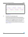
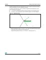
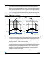
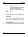
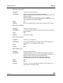
4.
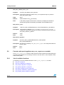
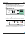
Measure the delay in electrical degrees between the maximum of the B-emf induced on
Phase A and the first rising edge of signal H1. Enter it in the MC_hall_param.h header
file (HALL_PHASE_SHIFT). For your convenience, an example with
HALL_PHASE_SHIFT equal to –90 °C is illustrated in Figure 27.
Figure 27. Determination of Hall electrical phase shift
34/121
UM0492
3.11
Running the demo program
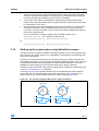
Progressive sensorless system development
In order to simplify sensorless development, a process was defined when designing the
presented firmware library. This process is a 4-step path that takes the user in a very short
time to the final achievement of running the motor without either speed or position feedback
sensors.
The defined process is based on the hypothesis that within the development stage of
design, the user can count on speed / position rotor information coming from either the Hall
sensors or the encoder. If not possible or not convenient in the application, it is anyway
sufficient to mechanically couple the shaft of the motor to the one of the motor mounting
sensors (e.g. the BLDC motor provided in the STM3210B-MCKIT). This feedback
information is actually necessary mainly for the purpose of comparing the rotor position
information observed by the sensorless algorithm to the real one. In this way, the sensorless
algorithm can be fine tuned.
As mentioned above, the path consists of 4 steps listed and described below:
1.
Run the motor in a pure sensor configuration:
To this purpose, you should:
2.
–
Tune the Iq and Id current loop regulator gains by following the instructions given
in appendix A.4 and A.5
–
Comment FLUX_TORQUE_PIDs_TUNING, run the motor in speed control and
tune the speed PI(D) gains. Derivative action can be enabled / disabled by
uncommenting / commenting the SPEED_DIFFERENTIAL_TERM_ENABLED line in
stm32f10x_MCconf.h.
Run the motor in sensor mode and tune the observer gains
The Clark and Parke transformation blocks and the speed regulator will utilize the rotor
position and speed information read by the sensor. The sensorless algorithm will be
run in parallel. To this purpose it is necessary to:
–
Precompute initial observer gains following the instructions provided in appendix
A.6
–
Uncomment OBSERVER_GAIN_TUNING in stm32f10x_MCconf.h.
–
Fill in MC_PMSM_motor_param.h (see Section 4.6) and
MC_State_Observer_param.h (startup section not required in this step, see
Section 4.5)
–
Real-time tune observer gains by visually comparing (through DAC functionality)
the observed and real Iα and Iβ (error must be null) and by making sure that the
observed B-emf waveforms are as clean and sinusoidal as possible. Real-time
tuning of PLL gains should not be required but, in case, proportionally increase Kp
and Ki to enlarge the PLL bandwidth (quickness to speed variation) and vice versa
–
Once the 4 gains have been found, write them in MC_State_Observer_param.h
35/121
Running the demo program
3.
UM0492
Run the motor in sensorless mode processing the sensor feedback:
The transformation blocks and the speed regulator will utilize the rotor position and
speed information coming from the sensorless algorithm (“observed value”). The real
(measured) information coming from the real sensors are processed for comparison
with the observed ones.
With this aim it is necessary to:
Note:
–
Uncomment NO_SPEED_SENSORS and a definition between
VIEW_HALL_FEEDBACK and VIEW_ENCODER_FEEDBACK (depending on the
sensor you are using)
–
Fill startup section of MC_State_Observer_param.h and relax at first statistic
parameters if motor cannot start with different current and frequency startup
parameters (“Error on speed fdbck” or “Start-up failed” faults)
Be aware that due to the different speed resolution/accuracy, a different setup for speed PID
could be necessary.
–
4.
Tune startup parameters performing different ramp-up trials and, if required,
further tune observer and PLL gains
Congratulations! The motor can now run in pure sensorless mode:
Depending on the requirements of the used debug feature, on the expected code size
and CPU load you could:
3.12
–
Comment VIEW_HALL_FEEDBACK or VIEW_ENCODER_FEEDBACK (depending on
which was not commented) in stm32f10x_MCconf.h
–
Comment OBSERVER_GAIN_TUNING in stm32f10x_MCconf.h
–
Comment DAC_FUNCTIONALITY in stm32f10x_MCconf.h
Setting up the system when using a brake resistor
Due to its physical construction, a PM synchronous motor is able to transform kinetic energy
into electrical energy just like a dynamo.
Under a limited number of conditions this property of PM synchronous motors has to be
taken into consideration to avoid possible damage to the hardware system. For instance, a
dangerous situation could arise when:
●
The six inverter switches are opened and the motor is running at a speed higher than
the nominal one. In this case, the amplitude of the line-to-line B-emf generated is
higher than the nominal bus voltage
●
The control tries to brake, an energy transfer from the load to the board occurs
Unless the used power system has regenerative capabilities, in both of these situations the
inverter bulk capacitor is charged. Furthermore, depending on the rotor speed (with
reference to the first situation) or on the amount of energy transferred (with reference to the
second situation), the voltage across the bulk capacitors could increase to a destructive
level.
A strategy for somehow dissipating the generated electrical energy is thus necessary.
Different methods could be implemented to do so, but one of them in particular, the
utilization of a brake resistor, is supported by the library presented in this user manual.
Caution:
36/121
If the motor is operated beyond the rated speed, it is mandatory to use a regenerative power
converter or a brake resistance to prevent bus overvoltage from damaging your board.
UM0492
3.12.1
Running the demo program
How to configure the FOC software library for brake resistor
management
To enable the management of the brake resistor on the STM32F103xx PMSM FOC
firmware library, simply uncomment the definition of BRAKE_RESISTOR in the
stm32f10x_MCconf.h header file.
The analog watchdog feature of the STM32F103xx allows to generate an interrupt whenever
the bus voltage goes above the OVERVOLTAGE_THRESHOLD_V parameter specified in
MC_Control_Param.h and as a consequence, the BRAKE_GPIO_PIN pin of the
BRAKE_GPIO_PORT port is set to high level (both definitions are in
MC_MotorControl_Layer.c, default values are GPIOD and GPIO_Pin_13 for compatibility
with STM3210B-MCKIT). From then on, a hysteresis control of the bus voltage is performed.
Hysteresis can be entered by editing the BRAKE_HYSTERESIS parameter in stm32f10x_it.c.
3.12.2
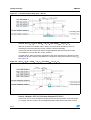
How to modify the MB459 board for brake resistor management
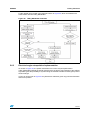
In order to make the MB459 board suitable for the management of a brake resistor, it is
necessary to solder some additional components on its wrapping area.
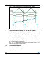
Figure 28 gives an example of the circuit to be used for the hardware implementation of the
brake.
Figure 28. Brake resistor circuit
Note that the size of the resistor in terms of both resistance and sustainable power should
be carefully dimensioned.
When using the PMSM FOC library in conjunction with the STM3210B-MCKIT, note that the
pin 23 of the MC connector (J7) that carries the signal for brake implementation is
positioned close to the wrapping area.
3.13
Note on debugging tools
The third party JTAG interface should always be isolated from the application using the
MB535 JTAG opto-isolation board; it provides protection for both the JTAG interface and the
PC connected to it.
37/121
Running the demo program
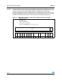
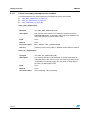
Caution:
UM0492
During a breakpoint, when using the JTAG interface for the firmware development, the motor
control cell clock circuitry should always be disabled; if enabled, a permanent DC current
may flow in the motor because the PWM outputs are enabled, which could cause
permanent damage to the power stage and/or motor. A dedicated bit in the DBGMCU_SR
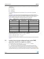
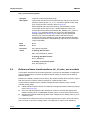
register, the DBG_TIM1_STOP bit, must be set to 1 (see Figure 25). In the main.c module
the DBG->CR |= DBG_TIM1_STOP; instruction performs the above described task.
Figure 29. DBG_TIM1_STOP bit in TIM1 control register (extract from STM32
reference manual)
DBGMCU_CR
Address: 0xE0042004
Only 32-bit access supported
POR Reset: 0x00000000 (not reset by system reset)
31
30
29
28
27
26
25
24
23
22
21
20
19
18
17
DBG_I2C
2_SMBU
S_TIMEO
UT
Reserved
Res.
38/121
15
14
13
12
11
10
9
8
DBG_I2C
1_SMBU
S_TIME
OUT
DBG_
CAN_
STOP
DBG_
TIM4_
STOP
DBG_
TIM3_
STOP
DBG_
TIM2_
STOP
DBG_
TIM1_
STOP
DBG_
WWDG_
STOP
DBG_
IWDG
STOP
rw
rw
rw
rw
rw
rw
rw
rw
16
rw
7
6
TRACE_
MODE
[1:0]
rw
rw
5
4
3
2
1
0
TRACE_
IOEN
Reserved
DBG_
STANDB
Y
DBG_
STOP
DBG_
SLEEP
rw
Res.
rw
rw
rw
UM0492
4
Getting started with the library
Getting started with the library
It is quite easy to set up an operational evaluation platform with a drive system that includes
the STM3210B-MCKIT (featuring the STM32F103xx microcontroller, where this software
runs) and a permanent-magnet motor.
This section explains how to quickly configure your system and, if necessary, customize the
library accordingly.
Follow these steps to accomplish this task:
1.
Gather all the information that is needed regarding the hardware in use (motor
parameters, power devices features, speed/position sensor parameters, current
sensors transconductance);
2.
Edit, using an IDE, the stm32f10x_MCconf.h configuration header file (as explained
in more detail in Section 4.1), and the following parameter header files,
3.
–
MC_Control_Param.h (see Section 4.2),
–
MC_encoder_param.h (see Section 4.3) or MC_hall_prm.h (see Section 4.4),
–
MC_State_Observer_param.h (see Section 4.5)
–
MC_PMSM_motor_param.h (see Section 4.6);
Re-build the project and download it on the STM32F103xx microcontroller.
Please be aware that this procedure should also be followed when the final target is a
sensorless drive. In fact, receiving speed/position information from any kind of sensor
makes it possible to achieve a more precise customization, and to tune the algorithm utilized
for sensorless rotor position reconstruction.
4.1
Library configuration file: stm32f10x_MCconf.h
The purpose of this file is to declare the compiler conditional compilation keys that are used
throughout the entire library compilation process to:
●
Select which current measurement technique is actually in use (the choice is between
three shunt or ICS sensors, according to availability)
●
Select which speed/position sensor is actually used (here the choice is between Hall
sensors, quadrature incremental encoder or no speed sensors, depending on the
requirements)
●
Enable or disable the derivative action in the speed controller or in the current
controllers in accordance with expected performance and code size.
●
Enable or disable the brake resistor management depending on requirements on brake
performance and on maximum speed
●
Enable or disable a virtual 2-channel DAC for real-time tracing of the most important
software variables. For the best debug support, user should keep this feature enabled
●
Enable or disable the execution of a specific software dedicated to the tuning of current
PIDs
●
Enable or disable the tuning of the State Observer and PLL gains
●
In case of "no speed sensor" it is still possible to acquire signals coming from Hall
sensors or encoder and evaluate whether the sensorless algorithm is working properly,
using the DAC functionality. Those signal will not be used in the FOC algorithm; the
choice here is between Hall sensors, quadrature incremental encoder or none.
39/121
Getting started with the library
UM0492
If this header file is not edited appropriately (no choice or undefined choice), you will receive
an error message when building the project. Note that you will not receive an error message
if the configuration described in this header file does not match the hardware that is actually
in use, or in case of wrong wiring.
More specifically:
●
#define ICS_SENSORS
To be uncommented when current sampling is done using isolated current sensors.
●
#define THREE_SHUNT
To be uncommented when current sampling is performed via three shunt resistors
(default).
●
#define ENCODER
To be uncommented when an incremental encoder is connected to the starter kit for
position sensing; in parallel, fill out MC_encoder_param.h (as explained in Section 4.3)
●
#define HALL_SENSORS
To be uncommented when three Hall sensors (60° or 120° displaced) are in use to
detect rotor speed (default); in parallel, fill out MC_hall_prm.h (as explained in
Section 4.4)
●
#define NO_SPEED_SENSORS
To be uncommented to use the rotor position information inside the FOC algorithm
(rotor position information is provided by a state observer). In this case, the user should
fill MC_State_Observer_param.h and MC_PMSM_motor_param.h in parallel (as
explained in Section 4.5 and Section 4.6, respectively)
●
#define VIEW_HALL_FEEDBACK
To be uncommented only in conjunction with NO_SPEED_SENSORS. It is used to
process the information that comes from three Hall sensors, to be displayed through
the DAC functionality (and compared with the information coming from the sensorless
rotor position reconstruction algorithm)
●
#define VIEW_ENCODER_FEEDBACK
To be uncommented only in conjunction with NO_SPEED_SENSORS. It is used to
process the information coming from an incremental encoder, to be displayed through
the DAC functionality (and compared with the information coming from the sensorless
rotor position reconstruction algorithm)
●
#define BRAKE_RESISTOR
To be uncommented to enable the software management of a resistive brake (refer to
Section 3.12.2 for more information about the hardware modifications to be applied to
the MB459 board)
40/121
UM0492
Getting started with the library
Caution:
In order to avoid any damage to the power stage, it is mandatory to utilize the brake resistor
feature for operation above the nominal speed.
●
#define Id_Iq_DIFFERENTIAL_TERM_ENABLED
To be uncommented when differential terms for torque and flux control loop regulation
(PID) are enabled
●
#define SPEED_DIFFERENTIAL_TERM_ENABLED
To be uncommented when differential term for speed control loop regulation (PID) is
enabled
●
#define FLUX_TORQUE_PIDs_TUNING
To be uncommented when a rotor position sensor is utilized. It generates a software
dedicated to torque and flux PID gain tuning. Fill MC_Control_Param.h in parallel
●
#define OBSERVER_GAIN_TUNING
If uncommented, it enables the visualization on LCD of a menu dedicated to state
observer and PLL gain tuning
●
#define DAC_FUNCTIONALITY
To be uncommented to enable the DAC functionality. Refer to Section 3.5 for more
detailed information about this feature.
Once these settings have been done, only the required blocks will be linked in the project;
this means that you do not need to exclude .c files from the build.
Caution:
When using shunt resistors for current measurement, ensure that the REP_RATE parameter
(in MC_Control_Param.h) is set properly (see Section 4.2 and Section A.2: Selecting the
update repetition rate based on the PWM frequency for 3 shunt resistor configuration on
page 111 for details).
4.2
Drive control parameters: MC_Control_Param.h
The MC_Control_Param.h header file gathers parameters related to:
●
Power device parameters on page 41
●
Current regulation parameters on page 42
●
Power board protection thresholds on page 42
●
Speed loop sampling time on page 42
●
Speed PID-controller init values on page 43
●
Quadrature current PID-controller init values on page 43
●
Linear variation of PID constants according to mechanical speed. on page 44
Power device parameters
●
#define PWM_FREQ
Define here, in Hz, the switching frequency; in parallel, uncomment the maximum
allowed modulation index definition (MAX_MODULATION_XX_PER_CENT)
corresponding to the PWM frequency selection.
●
#define DEADTIME_NS
Define here, in ns, the dead time, in order to avoid shoot-through conditions.
41/121
Getting started with the library
UM0492
Current regulation parameters
●
#define REP_RATE
Stator currents sampling frequency and consequently flux and torque PID regulators
sampling rate, are defined according to the following equation:
⋅ PWM_FREQFlux and torque PID sampling rate = 2
-------------------------------------------REP_RATE + 1
In fact, because there is no reason for either executing the FOC algorithm without updating
the stator currents values or for performing stator current conversions without running the
FOC algorithm, in the proposed implementation the stator current sampling frequency and
the FOC algorithm execution rate coincide.
Note:
REP_RATE must be an odd number if currents are measured by shunt resistors (see
Section A.2: Selecting the update repetition rate based on the PWM frequency for 3 shunt
resistor configuration on page 111 for details); its value is 8-bit long;
Power board protection thresholds
●
#define NTC_THRESHOLD_C
●
#define NTC_HYSTERIS_C
These two values (expressed in °C) are used to set the operating temperature range of the
power devices (measured at heat sink) when the software library is used with the MB459
board. In particular, if the measured temperature exceeds NTC_THRESHOLD_C, a fault event
is generated that is kept as long as the measured temperature remains below
NTC_THRESHOLD_C - NTC_HYSTERESIS_C.
●
#define
OVERVOLTAGE_THRESHOLD_V
●
#define
UNDERVOLTAGE_THRESHOLD_V
These two values (expressed in volt) set the minimum and maximum acceptable bus DC
voltage when the software library is utilized with the MB459 board. If the bus voltage
exceeds OVERVOLTAGE_THRESHOLD_V or is below UNDERVOLTAGE_THRESHOLD_V, a
fault event is generated that is kept as long as the bus voltage remains outside the allowed
range.
Speed loop sampling time
#define PID_SPEED_SAMPLING_TIME
The speed regulation loop frequency is selected by assigning one of the defines below:
#define
#define
#define
#define
#define
#define
#define
42/121
PID_SPEED_SAMPLING_500µs 0
//min 500µs
PID_SPEED_SAMPLING_1ms
1
PID_SPEED_SAMPLING_2ms
3
//(4-1)*500µs=2ms
PID_SPEED_SAMPLING_5ms 9
PID_SPEED_SAMPLING_10ms
19
PID_SPEED_SAMPLING_20ms 39
PID_SPEED_SAMPLING_127ms 255 //max(255-1)*500µs=127ms
UM0492
Getting started with the library
Speed PID-controller init values
●
#define PID_SPEED_REFERENCE_RPM
Define here, in rpm, the mechanical rotor speed setpoint at startup in closed loop
mode;
●
#define PID_SPEED_KP_DEFAULT
The proportional constant of the speed loop regulation (signed 16-bit value, adjustable
from 0 to 32767);
●
#define PID_SPEED_KI_DEFAULT
The integral constant of the speed loop regulation (signed 16-bit value, adjustable from
0 to 32767);
●
#define PID_SPEED_KD_DEFAULT
The derivative constant of the speed loop regulation (signed 16-bit value, adjustable
from 0 to 32767);
Quadrature current PID-controller init values
See Appendix A.4, which illustrates the method to be followed for computing initial PI
constants, starting from motor parameters and required control bandwidth.
●
#define PID_TORQUE_REFERENCE
The torque (Iq) reference value, in torque control mode, at startup (signed 16-bit value);
●
#define PID_TORQUE_KP_DEFAULT
The proportional constant of the torque loop regulation (signed 16-bit value, adjustable
from 0 to 32767);
●
#define PID_TORQUE_KI_DEFAULT
The integral constant of the torque loop regulation (signed 16-bit value, adjustable from
0 to 32767);
●
#define PID_TORQUE_KD_DEFAULT
The derivative constant of the torque loop regulation (signed 16-bit value, adjustable
from 0 to 32767);
●
#define PID_FLUX_REFERENCE
Flux (Id) reference: its default value is 0;
●
#define PID_FLUX_KP_DEFAULT
The proportional constant of the flux loop regulation (signed 16-bit value, adjustable
from 0 to 32767);
●
#define PID_FLUX_KI_DEFAULT
The integral constant of the flux loop regulation (signed 16-bit value, adjustable from 0
to 32767);
●
#define PID_FLUX_KD_DEFAULT
The derivative constant of the flux loop regulation (signed 16-bit value, adjustable from
0 to 32767);
●
#define SQUARE_WAVE_PERIOD
The period (in ms) of the square wave reference torque generated when
FLUX_TORQUE_PIDs_TUNING is uncommented in stm32f10x_MCconf.h
43/121
Getting started with the library
UM0492
Linear variation of PID constants according to mechanical speed.
Refer to Section 5.8.4: Adjusting speed regulation loop Ki, Kp and Kd vs. motor frequency
on page 98.
4.3
Incremental encoder parameters: MC_encoder_param.h
The MC_encoder_parameter.h header file is to be filled if position/speed sensing is
performed by means of a quadrature, square wave, relative rotary encoder (ENCODER or
VIEW_ENCODER_FEEDBACK defined in stm32f10x_MCconf.h).
●
#define TIMER2_HANDLES_ENCODER
To be uncommented if the two sensor output signals are wired to TIMER2 input pins
(default; required when using STM3210B-MCKIT);
●
#define TIMER3_HANDLES_ENCODER
To be uncommented if the two sensor output signals are wired to TIMER3 input pins;
●
#define TIMER4_HANDLES_ENCODER
To be uncommented if the two sensor output signals are wired to TIMER4 input pins.
●
#define ENCODER_PPR
Defines the number of pulses generated by a single channel, for one shaft revolution
(actual resolution will be 4x);
●
#define MINIMUM_MECHANICAL_SPEED_RPM
Defines in rpm, the minimum speed below which the speed measurement is either not
realistic or not safe in the application; an error counter is increased every time the
measured speed is below the specified value. In order to disable this check and control
the motor down to zero speed, the user can set this parameter to zero: a warning
message "pointless comparison of unsigned integer with zero" will be issued at
compilation time.
●
#define MAXIMUM_MECHANICAL_SPEED_RPM
Defines in rpm, the maximum speed above which the speed measurement is either not
realistic or not safe in the application; an error counter is increased every time the
measured speed is above the specified value.
●
#define MAXIMUM_ERROR_NUMBER
Defines the number of consecutive errors on speed measurements to be detected
before a fault event is generated (check rate is specified by SPEED_MEAS_TIMEBASE
in stm32f10x_Timebase.c).
●
#define SPEED_BUFFER_SIZE
Defines the buffer size utilized for averaging speed measurement. Power of two is
desirable for ease the computation.
Alignment settings:
Quadrature encoder is a relative position sensor. Considering that absolute information is
required for performing field oriented control, it is necessary to somehow establish a 0°
position. This task is performed by means of an alignment phase, and is carried out at first
motor startup and after any fault event. It basically consists in imposing a null reference
torque (Iq) and a reference flux (Id) with a linearly increasing magnitude and a constant
orientation.
44/121
UM0492
Getting started with the library
If properly configured, at the end of this phase, the rotor is locked in a well-known position
and the encoder timer counter is initialized accordingly.
The following parameters are used to customize the alignment phase depending on the
motor inertia and load conditions:
●
T_ALIGNMENT in milliseconds defines the desired duration of the alignment phase
●
ALIGNMENT_ANGLE specifies the vector orientation (angle θ in the below diagram)
Figure 30. Alignment angle
b
q
θ0
a
d
c
ai14833
●
I_ALIGNMENT (in digits) defines the final value of the reference Id magnitude. With
STM3210B-MCKIT and with ALIGNMENT_ANGLE set to 90° (default), the final phase A
current value can be computed by using the formula:
Alignment final phase A current = (I_ALIGNMENT * 0.64)/(32767*Rshunt)
45/121
Getting started with the library
4.4
UM0492
Hall sensor parameters: MC_hall_prm.h
The MC_hall_prm.h header file is to be filled if a position/speed sensing is performed by
means of three Hall sensors (HALL_SENSORS or VIEW_HALL_FEEDBACK defined in
stm32f10x_MCconf.h).
●
#define TIMER2_HANDLES_HALL
To be uncommented if the three sensor output signals are wired to TIMER2 input pins
(default; required if using STM3210B-MCKIT);
●
#define TIMER3_HANDLES_HALL
To be uncommented if the three sensor output signals are wired to TIMER3 input pins;
●
#define TIMER4_HANDLES_HALL
To be uncommented if the three sensor output signals are wired to TIMER4 input pins.
●
#define HALL_SENSORS_PLACEMENT
Defines the electrical displacement between the Hall sensors expressed in degrees
(physical displacement × number of pole pairs). The choice is between 120
(DEGREES_120) and 60 degrees (DEGREES_60).
●
#define HALL_PHASE_SHIFT
Defines the electrical phase shift (degrees) between the 0° angle, with the convention
utilized in the firmware, and the first rising edge on TIMx_CH1 (H1 signal with
STM3210B-MCKIT).
Refer to Section 3.10 for a detailed explanation on how to determine this parameter.
●
#define HALL_MAX_SPEED_FDBK_RPM
Defines the rotor mechanical frequency (rpm) above which speed feedback is not
realistic in the application: used to discriminate glitches for instance.
●
#define HALL_MAX_SPEED
This parameter is the value returned by the HALL_GetSpeed function (0.1 Hz unit) if
measured speed is greater than HALL_MAX_SPEED_FDBK_RPM. The default value is
500 Hz, but it can be 0 or FFFF depending on how this value is managed by the upper
layer software.
●
#define HALL_MAX_PSEUDO_SPEED
This parameter is the value returned by the HALL_GetRotorFreq function if
measured speed is greater than MAX_SPEED_FDBK. The unit is ddp. See Appendix A.7
for more details about how to convert Hertz into pseudofrequency.
●
#define HALL_MIN_SPEED_FDBK_RPM
Defines the rotor mechanical frequency below which speed feedback is not realistic in
the application.
●
46/121
#define HALL_MAX_RATIO
–
It defines the lowest speed that can be measured (when counter = 0xFFFF)
–
It also prevents the clock prescaler from decreasing excessively when the motor is
stopped. (This prescaler is automatically adjusted during each capture interrupt to
optimize the timing resolution.)
UM0492
Getting started with the library
●
#define HALL_MAX_OVERFLOWS
This is the maximum number of consecutive timer overflows taken into account. It is set
by default to 2: if the timer overflows more than twice (meaning that the Hall sensor
period has been increased by a factor of at least two between two consecutive valid
edges), the number of overflows is not counted anymore. This usually indicates that
information has been lost (Hall sensor timeout) or that speed is decreasing very
sharply. The corresponding timeout delay depends on the selected timer prescaler,
which is variable; the higher the prescaler (low speed), the longer the timeout period
(see also Section 5.6)
●
#define HALL_SPEED_FIFO_SIZE
This is the length of the software FIFO in which the latest speed measurements are
stored. This stack is necessary to compute rolling averages on several consecutive
pieces of data.
4.5
State observer parameters: MC_State_Observer_param.h
The MC_State_Observer_param.h is to be filled if the user wants to take advantage of
or evaluate the implemented sensorless algorithm for rotor position / speed detection. In that
case, the MC_PMSM_motor_param.h header file also has to be configured accordingly
(see Section 4.6).
See also Section 3.11, which guides you progressively through the steps that make a
sensorless system up and running.
The gathered parameters are related to the:
4.5.1
●
state observer
●
startup
●
measurement statistics and reliability
State observer parameters
●
#define MAX_CURRENT
In Amperes, defines the current value equivalent to an ADC conversion equal to 32767
(signed 16 bits max). If the current is measured by using shunt resistors then:
3.3
MAX_CURRENT = ----------------------------------------- , where:
2 ⋅ R shunt ⋅ A ν
●
–
Av is the gain of the amplifying network (Av = 2.57 on the MB459B kit board)
–
Rshunt is the shunt resistance (in Ohms)
#define BUS_ADC_CONV_RATIO
Defines the ratio between ADC input voltage and corresponding DC bus voltage.
●
#define K1
K1 (signed 32-bit value) is an element of the gain vector of the implemented state
observer (as described in Section 2.2). An “a priori” determination of K1 can be made
using the formulas given in Section A.5. When the motor is running, this initial value
can then be tuned using the LCD interface and evaluating the results. In that case, the
value of K1 read on the display is 10 times smaller.
47/121
Getting started with the library
●
UM0492
#define K2
K2 (signed 32-bit value) is an element of the gain vector of the implemented state
observer (as described in Section 2.2). An “a priori” determination of K2 can be made
using the formulas given in Section A.5. When the motor is running, this initial value
can then be tuned using the LCD interface and evaluating the results. In that case, the
value of K2 read on the display is 100 times smaller.
●
#define PLL_KP_GAIN
The default formula provides an “a priori” determination of the phase detector gain of
the PLL. Nonetheless, this (signed 16-bit) value can be tuned when the motor is
running, by using the LCD interface and evaluating the results. If necessary, the default
value can be overwritten with a more suitable one.
●
#define PLL_KI_GAIN
The default formula provides an “a priori” determination of the loop filter gain of the
PLL. Nonetheless, this (signed 16-bit) value can be tuned when the motor is running by
using the LCD interface and evaluating the results. If necessary, the default value can
be overwritten with a more suitable one.
●
#define F1, #define F2
These coefficients (signed 16-bit values) help amplify the observer equations, so that
motor winding resistance and inductance can give a valuable contribution.
Maximum value is 215 = 32768
Note:
4.5.2
Depending on several system parameters (motor parameters, state observer parameters,
sampling frequency, current and voltage conversion parameters), compilation errors [Pe068]
or/and [Pe069] may occur in the MC_State_Observer_Interface.c source file. In that
case, the user should follow the procedure below to solve the problem:
1
Jump to the code line where the error was reported and see which Cx factor (x=1..5) caused
the issue.
2
Go to the definition of that Cx factor (in MC_State_Observer_param.h) and assess
whether F1 or F2 is involved.
3
Decrease F1 or F2 accordingly, always choosing positive powers of two.
Startup parameters
Rotor position reconstruction is based on the observation of the back-emfs generated when
the rotor is running. Therefore, a startup procedure has been implemented in order to spin
the motor when starting from standstill: a rotating stator flux is generated by a three-phase
symmetrical current, thus causing the rotor to follow.
The startup procedure has assumedly ended successfully when the observation of the
back-emfs becomes reliable, according to the parameters explained in Section 4.5.3 (and
the main state machine switches from Start to Run) otherwise a timeout occurs (in that case
the main state machine switches from Start to Fault).
The parameters described in this section are used to adapt the startup to the application by
customizing the amplitude and frequency profiles (see Figure 31) of the three-phase current
system.
48/121
UM0492
Getting started with the library
Figure 31. Startup current system frequency and amplitude profile
●
#define FREQ_START_UP_DURATION
In milliseconds, defines the overall time allowed for startup.
●
#define FINAL_START_UP_SPEED
In RPM, defines the speed of the rotating stator flux, and hence of the rotor, at the end
of the overall time allowed for startup (this parameter sets the slope of the frequency
linear ramp-up).
●
#define FIRST_I_STARTUP
In digits, defines the initial amplitude of the three-phase current system according to
the formula below:
I(Amps) ⋅ R shunt ⋅ A ν ⋅ 65536
I(digit) = ----------------------------------------------------------------------------------3.3
●
#define FINAL_I_STARTUP
In digits, defines the final amplitude of the three-phase current system according to the
above formula. This amplitude should be chosen to generate an electromagnetic
torque Te that matches the estimated load applied.
●
#define I_STARTUP_DURATION
In milliseconds, defines the time allowed to increase current amplitude linearly from
initial to final amplitude.
●
#define MINIMUM_SPEED_RPM
In RPM, defines the minimum speed at which the startup procedure may end (if the
rotor speed / position detection is considered reliable) to make way for normal
operations.
49/121
Getting started with the library
4.5.3
UM0492
Statistics parameters
State observer output results are continuously monitored to statistically assess the reliability
of the rotor speed / position information supplied. Since this technique is used as a fault
detection system, the parameters described in this section are used to set the desired safety
level.
●
#define VARIANCE_THRESHOLD
This parameter sets the threshold for the speed measurement variance. The
sensorless algorithm calculation is not considered reliable if the variance of the
observed speed is greater than the desired percentage of the mean value, according to
2
2
the formula: σ ≥ µ ⋅ VARIANCE_THRESHOLD , where σ and µ are the variance and the
mean value of the observed speed, respectively (for instance, a
VARIANCE_THRESHOLD of 0.0625 leads to a percentage of the mean value equal to
25%).
The lower the VARIANCE_THRESHOLD parameter, the more strict (and hence the
higher the safety level) of this fault detection algorithm, and vice versa.
●
#define RELIABILITY_HYSTERESIS
This (unsigned 8-bit) parameter defines the number of consecutive times the speed
measurement variance should be found higher than the VARIANCE_THRESHOLD
threshold before the rotor speed / position detection algorithm is declared nonreliable.
In this case, the main state machine switches from Run to Fault (see Section 3.7 about
the fault messages and Section 5.7 about the functions that implement this method).
●
#define NB_CONSECUTIVE_TESTS
Defines the number of consecutive times the speed measurement variance should be
found lower than the VARIANCE_THRESHOLD threshold before the startup procedure is
declared to have successfully completed. In this case, the main state machine switches
from Start to Run (see Section 3.7 about the fault messages).
4.6
Permanent-magnet synchronous motor parameters:
MC_PMSM_motor_param.h
The MC_PMSM_motor_param.h is to be filled with the motor parameters. Three different
sections can be distinguished:
4.6.1
●
Parameters needed to carry out the FOC
●
Parameters needed to perform sensorless rotor speed / position detection
●
Parameters needed to perform the flux weakening functionality
Basic motor parameters
This is the minimum set of motor parameters to be known in order to carry out FOC:
●
#define POLE_PAIR_NUM
Defines the number of magnetic pole pairs.
●
#define NOMINAL_CURRENT
In digits, defines the motor nominal current (0 to peak) according to the formula:
I(Amps) ⋅ R shunt ⋅ A ν ⋅ 65536
-.
I(digit) = ----------------------------------------------------------------------------------3.3
Of course, these data are to be matched with inverter current rating.
50/121
UM0492
Getting started with the library
●
#define MOTOR_RATED_SPEED_RPM
In RPM, defines the motor rated speed. This parameter could be set depending on the
mechanical construction of the motor, the application specifications, or it could be
worked out using the provided spreadsheet (see Section 4.6.3)
Note:
If the flux weakening functionality is not to be used, then #define EXT_SPEED_RANGE
should be set to 1.
4.6.2
Motor parameters for sensorless FOC
These parameters are used by the state observer algorithm to detect the rotor speed and
position (see also Section 4.5):
–
#define RS
Defines the motor winding resistance (phase) in Ohms.
–
#define LS
Defines the motor winding inductance (phase) in Henry.
–
#define MOTOR_VOLTAGE_CONSTANT
Defines the motor voltage constant Ke (V/krpm RMS phase to phase) in Volts.
4.6.3
Additional parameters for flux weakening operation
This section has to be filled if, depending on the application specifics, the drive has to
operate the motor beyond its rated speed (here, rated speed is considered to be the highest
speed at which the motor can deliver maximum torque).
The mechanical limit of the motor must not be exceeded in any case. Moreover, if the motor
is being operated beyond the rated speed, it is mandatory to have a regenerative power
converter or a brake resistance (see Section 3.12).
See Section 2.3 about the strategy implemented for flux weakening control.
●
#define MOTOR_VOLTAGE_CONSTANT
Defines the motor voltage constant Ke (V/krpm RMS phase to phase) in Volts.
The editing of the following parameters requires that the annexed spreadsheet is filled with
the information below:
●
Mains AC voltage, Volts RMS, cell B
●
Motor rated current, 0-to-peak Amperes, cell B2. These data must be matched with
inverter current rating.
●
Motor winding inductance, mH, phase, cell B3
●
Motor voltage constant Ke, Volts RMS/krpm, phase-to-phase, cell B4
●
Motor winding resistance, Ohms, cell B5
●
Number of magnetic pole pairs, cell B6
●
Maximum operating speed required by the application in the flux weakening region, cell
B7
●
Maximum modulation index MMI, %, cell B9. It is a function of the applied PWM
frequency (see Section 4.2)
●
Shunt resistance, Ohms, cell B10
●
Amplification network gain (shunt current reading), cell B11
51/121
Getting started with the library
UM0492
As a result of data processing, the following information can be obtained from the
spreadsheet:
●
#define MOTOR_RATED_SPEED_RPM
This is the motor rated speed, according to the definition above, it is the highest speed
for which the torque is maximum. The user can copy it from cell B15 (the mechanical
limit of the motor must not be exceeded in any case).
●
#define EXT_SPEED_RANGE
This is the ratio between the maximum and the rated rotor speed (cell B16 in the
spreadsheet)
●
#define ID_REFERENCE
For each rotor speed beyond the rated one, this is the table that defines the most
suitable value of the reference current component ids (digit). This table has to be copied
from cell B17
●
#define IQ_SATURATION
For each rotor speed beyond the rated one, this is the table that defines the saturation
value for the current component iqs (digit). This table has to be copied from cell B18.
52/121
UM0492
5
Library functions
Library functions
Functions are described in the format given below:
Synopsis
Lists the prototype declarations.
Description
Describes the functions specifically with a brief explanation of how they
are executed.
Input
Gives the format and units.
Returns
Gives the value returned by the function, including when an input value
is out of range or an error code is returned.
Note
Indicates the limits of the function or specific requirements that must be
taken into account before implementation.
Caution
Indicates important points that must be taken into account to prevent
hardware failures.
Functions called
Lists called functions. Useful to prevent conflicts due to the
simultaneous use of resources.
Code example
Indicates the proper way to use the function, and if there are certain
prerequisites (interrupt enabled, etc.).
Some of these sections may not be included if not applicable (for example, no parameters or
obvious use).
5.1
Current reading in three shunt resistor topology and space
vector PWM generation: stm32f10x_svpwm_3shunt module
Two important tasks are performed in the stm32f10x_svpwm_3shunt module:
●
Space vector pulse width modulation (SVPWM)
●
Current reading in three shunt resistor topology
In order to reconstruct the currents flowing through a three-phase load with the required
accuracy using three shunt resistors, it is necessary to properly synchronize A/D
conversions with the generated PWM signals. This is why the two tasks are included in a
single software module.
5.1.1
List of available functions
The following is a list of available functions as listed in the
stm32f10x_svpwm_3shunt.h header file:
●
SVPWM_3ShuntInit on page 54
●
SVPWM_3ShuntCurrentReadingCalibration on page 55
●
SVPWM_3ShuntGetPhaseCurrentValues on page 55
●
SVPWM_3ShuntCalcDutyCycles on page 56
●
SVPWM_3ShuntAdvCurrentReading on page 56
53/121
Library functions
UM0492
SVPWM_3ShuntInit
Synopsis
void SVPWM_3ShuntInit(void);
Description
The purpose of this function is to set-up microcontroller peripherals for
performing 3 shunt resistor topology current reading and center aligned
PWM generation.
The function initializes NVIC, ADC, GPIO, TIM1 peripherals.
In particular, the ADC and TIM1 peripherals are configured to perform
two simultaneous A/D conversions per PWM switching period.
Refer to Section 5.1.3 for further information.
Input
None.
Returns
None.
Note
It must be called at main level.
Functions called Standard library:
RCC_ADCCLKConfig, RCC_AHBPeriphClockCmd,
RCC_APB2PeriphClockCmd, GPIO_StructInit, GPIO_Init,
GPIO_PinLockConfig,GPIO_PinRemapConfig, TIM1_DeInit,
TIM1_TimeBaseStructInit, TIM1_TimeBaseInit, TIM1_OCStructInit,
TIM1_OC1Init, TIM1_OC2Init, TIM1_OC3Init, TIM1_OC4Init,
TIM1_OC1PreloadConfig, TIM1_OC2PreloadConfig,
TIM1_OC3PreloadConfig, TIM1_OC4PreloadConfig,
TIM1_BDTRConfig, TIM1_SelectOutputTrigger,
TIM1_ClearITPendingBit, TIM1_ITConfig,
TIM1_Cmd,TIM1_GenerateEvent, TIM1_ClearFlag, ADC_DeInit,
ADC_Cmd, ADC_StructInit, ADC_Init, ADC_StartCalibration,
ADC_GetCalibrationStatus, ADC_RegularChannelConfig,
ADC_InjectedSequencerLengthConfig, ADC_InjectedChannelConfig,
NVIC_PriorityGroupConfig, NVIC_StructInit, NVIC_Init.
Motor control library:
SVPWM_3ShuntCurrentReadingCalibration
54/121
UM0492
Library functions
SVPWM_3ShuntCurrentReadingCalibration
Synopsis
void SVPWM_3ShuntCurrentReadingCalibration(void);
Description
The purpose of this function is to store the three analog voltages
corresponding to zero current values for compensating the offset
introduced by the amplification network.
Input
None.
Returns
None.
Note
This function reads the analog voltage on the ADC channels used for
current reading. For this reason it must be called before the PWM
outputs are enabled so that the current flowing through the inverter is
zero. Those values are then stored into Phase_x_Offset variables.
Functions called
Standard library:
ADC_ITConfig, ADC_ExternalTrigInjectedConvConfig,
ADC_ExternalTrigInjectedConvCmd,
ADC_InjectedSequencerLengthConfig,
ADC_InjectedChannelConfig, ADC_ClearFlag,
ADC_SoftwareStartInjectedConvCmd, ADC_GetFlagStatus,
ADC_GetInjectedConversionValue,
ADC_SoftwareStartInjectedConvCmd
Motor control library:
SVPWM_InjectedConvConfig
SVPWM_3ShuntGetPhaseCurrentValues
Synopsis
Curr_Components SVPWM_3ShuntGetPhaseCurrentValues(void);
Description
This function computes current values of Phase A and Phase B in
q1.15 format starting from values acquired from the A/D Converter
peripheral.
Input
None.
Returns
Curr_Components type variable.
Note
In order to have a q1.15 format for the current values, the digital value
corresponding to the offset must be subtracted when reading phase
current A/D converted values. Therefore, the function must be called
after SVPWM_3ShuntCurrentReadingCalibration.
Functions called None.
55/121
Library functions
UM0492
SVPWM_3ShuntCalcDutyCycles
Synopsis
void SVPWM_3ShuntCalcDutyCycles (Volt_Components
Stat_Volt_Input);
Description
After executing the FOC algorithm, new stator voltage components Vα
and Vβ are computed. The purpose of this function is to calculate
exactly the three duty cycles to be applied to the inverter legs starting
from the values of these voltage components.
Moreover, once the three duty cycles to be applied in the next PWM
period are known, this function sets the Channel 4 output compare
register used to set the sampling point for the next current reading. In
particular, depending on the duty cycle values, the sampling point is
computed (see Section 5.1.3).
Refer to Section 5.1.2 for information on the theoretical approach of
SVPWM.
Input
Vα and Vβ
Returns
None.
Note
None.
Functions called None.
SVPWM_3ShuntAdvCurrentReading
Synopsis
void SVPWM_3ShuntAdvCurrentReading(FunctionalState cmd);
Description
It is used to enable or disable advanced current reading. If advanced
current reading is disabled, current reading is performed in conjunction
with the update event.
Input
cmd (ENABLE or DISABLE)
Returns
None.
Note
None.
Functions called TIM1_ClearFlag, TIM1_ITConfig
56/121
UM0492
5.1.2
Library functions
Space vector PWM implementation
Figure 32 shows the stator voltage components Vα and Vβ while Figure 33 illustrates the
corresponding PWM for each of the six space vector sectors.
Figure 32. Vα and Vβ stator voltage components
Figure 33. SVPWM phase voltages waveforms
57/121
Library functions
UM0492
With the following definitions for: U α =
3 × T × V α , U β = – T × V β and X = U β ,
Uβ – Uα
Uα + Uβ
- and Z = -------------------.
Y = ------------------2
2
literature demonstrates that the space vector sector is identified by the conditions shown in
Table 1.
Table 1.
Sector identification
Y≥0
Y<0
Z≥0
Z<0
Sector
V
Z≥0
Z<0
X ≤0
X>0
X ≤0
X>0
IV
III
VI
I
II
The duration of the positive pulse widths for the PWM applied on Phase A, B and C are
respectively computed by the following relationships:
+ X – Z- , t = t + Z , t = t – X
Sector I, IV: t A = T
---------------------B
A
C
B
2
+ Y – Z- , t = t + Z , t = t – Y
Sector II, V: t A = T
---------------------B
A
C
A
2
– X + Y- t = t + X t = t – Y
----------------------Sector III, VI: t A = T
, B
, C
, where T is the PWM period.
C
A
2
Now, considering that the PWM pattern is center aligned and that the phase voltages must
be centered at 50% of duty cycle, it follows that the values to be loaded into the PWM output
compare registers are given respectively by:
⁄ 2 + X – Z- , TimePhB = TimePhA + Z , TimePhC = TimePhB – X
Sector I, IV: TimePhA = T
--- + T
--------------------------------4
2
⁄ 2 + Y – Z- , TimePhB = TimePhA + Z , TimePhC = TimePhA – Y
Sector II, V: TimePhA = T
--- + T
--------------------------------4
2
⁄ 2 + Y – X- , TimePhB = TimePhC + X , TimePhC = TimePhA – Y
Sector III,VI: TimePhA = T
--- + T
--------------------------------4
5.1.3
2
Current sampling in three shunt topology and general purpose A/D
conversions
The three currents I1, I2, and I3 flowing through a three-phase system follow the
mathematical relation:
I1 + I2 + I3 = 0
For this reason, to reconstruct the currents flowing through a generic three-phase load, it is
sufficient to sample only two out of the three currents while the third one can be computed
by using the above relation.
The flexibility of the STM32F103xx A/D converter makes it possible to synchronously
sample the two A/D conversions needed for reconstructing the current flowing through the
motor. The ADC can also be used to synchronize the current sampling point with the PWM
output using the external triggering capability of the peripheral. Owing to this, current
conversions can be performed at any given time during the PWM period. To do this, the
58/121
UM0492
Library functions
control algorithm uses the fourth PWM channel of TIM1 to synchronize the start of the
conversions.
Injected conversions, as described above, are used for current-reading purposes whereas
regular conversions are reserved for the user. As soon as the injected A/D conversions for
current-reading purposes have completed, bus voltage and temperature sensing are also
simultaneously converted by the dual A/D.
Figure 34 shows the synchronization strategy between the TIM1 PWM output and the ADC.
The A/D converter peripheral is configured so that it is triggered by the rising edge of
TIM1_CH4.
Figure 34. PWM and ADC synchronization
Counter overflow
OCR 4
OCR 4
OCR 1
OCR 1
OCR 2
OCR 2
OCR 3
OCR 3
TIM1_CH1
TIM1_CH1
TIM1_CH2
TIM1_CH2
ADC Start
ADC Start
TIM1_CH3
TIM1_CH3
TIM1_CH4
TIM1_CH4
Sampling point before counter overflow
Sampling point after counter overflow
ai14835
In this way, supposing that the sampling point must be set before the counter overflow, that
is, when the TIM1 counter value matches the OCR4 register value during the upcounting,
the A/D conversions for current sampling are started. If the sampling point must be set after
the counter overflow, the PWM 4 output has to be inverted by modifying the CC4P bit in the
TIM1_CCER register. In so doing, when the TIM1 counter matches the OCR4 register value
during the downcounting, the A/D samplings are started.
After the first two simultaneous conversions other two simultaneous conversions are started,
one for the bus voltage and the other for the temperature sensing. At the end of the second
conversion, the three-phase load current has been updated and the FOC algorithm can then
be executed in the A/D end of injected conversion interrupt service routine (JEOC ISR).
After execution of the FOC algorithm, the value to be loaded into the OCR4 register is
calculated to set the sampling point for the next PWM period, and the A/D converter is
configured to sample the correct channels.
59/121
Library functions
UM0492
Regular conversions are reserved for user purposes and must be configured manually (See
also firmware standard library user manual UM0427).
5.1.4
Tuning delay parameters and sampling stator currents in three shunt
resistor topology
Figure 35 shows one of the three inverter legs with the related shunt resistor:
Figure 35. Inverter leg and shunt resistor position
To indirectly measure the phase current I, it is possible to read the voltage V providing that
the current flows through the shunt resistor R.
It is possible to demonstrate that, whatever the direction of current I, it always flows through
the resistor R if transistor T2 is switched on and T1 is switched off. This implies that in order
to properly reconstruct the current flowing through one of the inverter legs, it is necessary to
properly synchronize the conversion start with the generated PWM signals. This also means
that current reading cannot be performed on a phase where the duty cycle applied to the low
side transistor is either null or very short.
Fortunately, as discussed in Section 5.1.3,to reconstruct the currents flowing through a
generic three-phase load, it is sufficient to simultaneously sample only two out of three
currents, the third one being computed from the relation given in Section 5.1.3. Thus,
depending on the space vector sector, the A/D conversion of voltage V will be performed
only on the two phases where the duty cycles applied to the low side switches are the
highest. In particular, by looking at Figure 33, you can deduct that in sectors 1 and 6, the
voltage on the Phase A shunt resistor can be discarded; likewise, in sectors 2 and 3 for
Phase B, and finally in sectors 4 and 5 for Phase C.
Moreover, in order to properly synchronize the two stator current reading A/D conversions, it
is necessary to distinguish between the different situations that can occur depending on
PWM frequency and applied duty cycles.
Note:
60/121
The explanations below refer to space vector sector 4. They can be applied in the same
manner to the other sectors.
UM0492
Library functions
Case 1: Duty cycle applied to Phase A low side switch is larger than
DT+TN
Where:
●
DT is dead time.
●
TN is the duration of the noise induced on the shunt resistor voltage of a phase by the
commutation of a switch belonging to another phase.
●
TS is the sampling time of the STM32F103xx A/D converter (the following consideration
is made under the hypothesis that TS < DT + TN). Refer to the STM32F103xx reference
manual for more detailed information.
This case typically occurs when SVPWM with low (<60%) modulation index is generated
(see Figure 36). The modulation index is the applied phase voltage magnitude expressed as
a percentage of the maximum applicable phase voltage (the duty cycle ranges from 0% to
100%).
Figure 37 offers a reconstruction of the PWM signals applied to low side switches of Phase
A and B in these conditions plus a view of the analog voltages measured on the
STM32F103xx A/D converter pins for both Phase B and C (the time base is lower than the
PWM period).
Figure 36. Low side switches gate signals (low modulation indexes)
Note that these current feedbacks are constant in the view in Figure 37 because it is
assumed that commutations on Phase B and C have occurred out of the visualized time
window.
Moreover, it can be observed that in this case the two stator current sampling conversions
can be performed synchronized with the counter overflow, as shown in Figure 37.
61/121
Library functions
UM0492
Figure 37. Low side Phase A duty cycle > DT+TN
ai14836b
Case 2: (DT+TN+TS)/2 < ∆DutyA < DT+TN and ∆DutyAB < DT+TR+TS
With the increase in modulation index, ∆DutyA can have values smaller than DT+TN.
Sampling synchronized with the counter overflow could be impossible.
In this case, the two currents can still be sampled between the two Phase A low side
commutations, but only after the counter overflow.
Consider that in order to avoid the acquisition of the noise induced on the phase B current
feedback by phase A switch commutations, it is required to wait for the noise to be over (TN).
See Figure 38.
Figure 38. (DT+TN+TS)/2 < ∆DutyA < DT+TN and ∆DutyAB < DT+TR+TS
ai14837b
Case 3: ∆DutyA < (DT+TN+TS)/2 and ∆DutyA-B>DT+TR+TS
In this case, it is no more possible to sample the currents during Phase A low-side switchon. Anyway, the two currents can be sampled between Phase B low-side switch-on and
62/121
UM0492
Library functions
Phase A high-side switch-off. The choice was therefore made to sample the currents TS µs
before of phase A high-side switch-off (see Figure 39).
Figure 39. ∆DutyA < (DT+TN+TS)/2 and ∆DutyA-B>DT+TR+TS
ai14838b
Case 4: ∆DutyA<(DT+TN+TS)/2 and ∆DutyA-B<DT+TR+TS
In this case, the duty cycle applied to Phase A is so short that no current sampling can be
performed between the two low-side commutations.
Furthermore if the difference in duty cycles between Phases B and A is not long enough to
allow the A/D conversions to be performed between Phase B low-side switch-on and Phase
A high-side switch-off, it is impossible to sample the currents (See Figure 40).
To avoid this condition, it is necessary to reduce the maximum modulation index or decrease
the PWM frequency.
Figure 40. ∆DutyA<(DT+TN+TS)/2 and ∆DutyA-B<DT+TR+TS
ai14839b
63/121
Library functions
UM0492
The following parameters have been set as default in the firmware. They are related to the
MB459 board:
●
DT = 0.8 µs
●
TN = 2.55 µs
●
TS = 0.7 µs
●
TR = 2.55 µs
The maximum applicable duty cycles are listed in Table 2 as a function of the PWM
frequency.
The values in Table 2 are measured using the MB459 board. This evaluation platform is
designed to support several motor driving topologies (PMSM and AC induction) and current
reading strategies (single- and three-shunt resistor). Therefore, the figures provided in
Table 2 should be understood as a starting point and not as a best case.
Table 2.
PWM frequency vs. maximum duty cycle relationship
PWM frequency
Max duty cycle
Max modulation Index
Up to 11.4 kHz
100%
100%
12.2 kHz
99%
98%
12.9 kHz
98.5%
97%
13.7 kHz
98%
96%
14.4 kHz
98%
96%
15.2 kHz
97%
94%
16 kHz
96.5%
93%
16.7 kHz
96.5%
93%
17.5 kHz
95.5%
91%
It is possible to adjust the noise parameters based on customized hardware by editing the
following definitions in the MC_pwm_3shunt_prm.h header file:
#define SAMPLING_TIME_NS 700 //0.7usec
#define TNOISE_NS 2550 //2.55usec
#define TRISE_NS 2550 //2.55usec
Changing the noise parameters, sampling time and dead time affects the values provided in
Table 2.
5.2
Isolated current sensor reading and space vector PWM
generation: stm32f10x_svpwm_ics module
Two important tasks are performed in the stm32f10x_svpwm_ics module.
●
Space vector pulse width modulation (SVPWM),
●
Three-phase current reading when two isolated current sensors (ICS) are used.
In order to reconstruct the currents flowing through a three phase load with the required
accuracy using two ICSs, it is necessary to properly synchronize A/D conversions with the
generated PWM signals. This is why the two tasks are included in a single software module.
64/121
UM0492
5.2.1
Library functions
List of available functions and interrupt service routines
The following is a list of available functions as listed in the stm32f10x_svpwm_ics.h
header file:
●
SVPWM_IcsInit on page 65
●
SVPWM_IcsCurrentReadingCalibration on page 66
●
SVPWM_IcsGetPhaseCurrentValues on page 66
●
SVPWM_IcsCalcDutyCycles on page 67
SVPWM_IcsInit
Synopsis
void SVPWM_IcsInit(void);
Description
The purpose of this function is to set-up microcontroller peripherals for
performing ICS reading and center aligned PWM generation.
The function initializes NVIC, ADC, GPIO, and TIM1 peripherals.
In particular, the ADC and TIM1 peripherals are configured to perform
two pairs of simultaneous injected A/D conversions every time the
PWM registers are updated (event called U event). The first pair of
conversions read the current values whereas the second pair acquires
the bus voltage and the voltage at the temperature sensor.
Refer to Section 5.2.2 for further information on A/D conversion
triggering in ICS configuration.
Input
None.
Returns
None.
Note
It must be called at main level.
Functions called Standard library:
RCC_ADCCLKConfig, RCC_AHBPeriphClockCmd,
RCC_APB2PeriphClockCmd, GPIO_StructInit, GPIO_Init,
GPIO_PinLockConfig, GPIO_PinRemapConfig, TIM1_DeInit,
TIM1_TimeBaseStructInit, TIM1_TimeBaseInit, TIM1_OCStructInit,
TIM1_OC1Init, TIM1_OC2Init, TIM1_OC3Init, TIM1_BDTRConfig,
TIM1_SelectOutputTrigger, TIM1_ClearITPendingBit, TIM1_ITConfig,
TIM1_Cmd, ADC_DeInit, ADC_Cmd, ADC_StructInit, ADC_Init,
ADC_StartCalibration, ADC_GetCalibrationStatus,
ADC_InjectedSequencerLengthConfig, ADC_InjectedChannelConfig,
ADC_ExternalTrigInjectedConvCmd, NVIC_PriorityGroupConfig,
NVIC_StructInit, NVIC_Init.
Motor control library:
SVPWM_IcsCurrentReadingCalibration
65/121
Library functions
UM0492
SVPWM_IcsCurrentReadingCalibration
Synopsis
void SVPWM_IcsCurrentReadingCalibration(void);
Description
The purpose of this function is to store the two analog voltages
corresponding to zero current values for compensating the offset
introduced by both ICS and amplification network.
Input
None.
Returns
None.
Note
This function is called by MCL_Init which is executed at every motor
startup. It reads the analog voltage on the A/D channels used for
current reading before the PWM outputs are enabled so that the
current flowing through the inverter is zero.
Functions called Standard Library:
ADC_ITConfig, ADC_ExternalTrigInjectedConvConfig,
ADC_ExternalTrigInjectedConvCmd, ADC_InjectedChannelConfig,
ADC_ClearFlag, ADC_SoftwareStartInjectedConvCmd,
ADC_GetFlagStatus, ADC_GetInjectedConversionValue,
SVPWM_IcsInjectedConvConfig
Motor Control library:
SVPWM_IcsInjectedConvConfig
SVPWM_IcsGetPhaseCurrentValues
Synopsis
Curr_Components SVPWM_IcsGetPhaseCurrentValues(void);
Description
This function computes current values of Phase A and Phase B in
q1.15 format from the values acquired from the A/D converter.
Input
None.
Returns
Curr_Components type variable
Note
In order to have a q1.15 format for the current values, the digital value
corresponding to the offset must be subtracted when reading phase
current A/D converted values. Thus, the function must be called after
SVPWM_IcsCurrentReadingCalibration.
Functions called None.
66/121
UM0492
Library functions
SVPWM_IcsCalcDutyCycles
Synopsis
void SVPWM_IcsCalcDutyCycles (Volt_Components
Stat_Volt_Input);
Description
After execution of the FOC algorithm, new stator voltages component
Vα and Vβ are computed. The purpose of this function is to calculate
exactly the three duty cycles to be applied to the three inverter legs
starting from the values of these voltage components.
Refer to Section 5.1.2 for details about the theoretical approach of
SVPWM and its implementation.
5.2.2
Input
Vα and Vβ
Returns
None.
Note
None.
Functions called
None.
Current sampling in isolated current sensor topology and integrating
general-purpose A/D conversions
The three currents I1, I2, and I3 flowing through a three-phase system follow the
mathematical relationship:
I1 + I2 + I3 = 0
Therefore, to reconstruct the currents flowing through a generic three-phase load, it is
sufficient to sample only two out of the three currents while the third one can be computed
by using the above relationship.
The flexibility of the STM32F103xx A/D converter trigger makes it possible to synchronize
the two A/D conversions necessary for reconstructing the stator currents flowing through the
motor with the PWM reload register updates. The update rate can be adjusted using the
repetition counter. This is important because, as shown in Figure 41, it is precisely during
counter overflow and underflow that the average level of current is equal to the sampled
current. Refer to the STM32F103xx reference manual to learn more about A/D conversion
triggering and the repetition counter.
Note:
Regular conversions are reserved for the user and must be configured manually (See also
firmware standard library user manual UM0427).
67/121
Library functions
UM0492
Figure 41. Stator currents sampling in ICS configuration (REP_RATE=1)
PWM Counter
Compare A
Compare B
Low side A
Low side B
Phase current
Average current
TIM1 Update,
TIM1 Update,
TIM1 Update,
ADC trigger
ADC trigger
ADC trigger
ai14840
5.3
PMSM field-oriented control: MC_FOC_Drive module
The MC_FOC_Drive module, designed for permanent-magnet synchronous motors,
provides, at the core, decoupled electromagnetic torque (Te) regulation and, to some extent,
flux weakening capability. In addition, it provides speed regulation by PID feedback control.
To operate, it requires no adjustment with all of the selectable current or speed sensing
configurations (in accordance with the settings in the stm32f10x_MCconf.h file):
●
isolated current sensing (ICS)
●
three-shunt resistor current sensing
●
encoder position and speed sensing
●
Hall sensor position and speed sensing
●
sensorless position and speed detection
The MC_FOC_Drive module handles several functions of other modules, and has no direct
access to the microcontroller peripheral registers.
5.3.1
68/121
List of available C functions
●
FOC_Model on page 69
●
FOC_CalcFluxTorqueRef on page 70
UM0492
Library functions
FOC_Model
Synopsis
void FOC_Model (void)
Description
The purpose of this function is to perform PMSM torque and flux
regulation, implementing the FOC algorithm.
Current commands iqs* and ids* (which, under field oriented conditions,
can control machine torque and flux respectively) are defined outside this
function (in Speed control mode they are provided, by means of speed
and flux regulators, by the FOC_CalcFluxTorqueRef function, while in
Torque control mode they are settled by the user).
Therefore, as a current source is required, the function has to run the
power converter as a CR-PWM. For this purpose, it implements an high
performance synchronous (d, q) frame current regulator, whose operating
frequency is defined, as explained in Section 4.2, by the parameter
REP_RATE (in conjunction with PWM_FREQ).
Triggered by ADC JEOC ISR, the function loads stator currents (read by
ICS or shunt resistors) and carries out Clark and Park transformations,
converting them to iqs and ids (see Figure 5).
Then, these currents are fed to PID regulators together with reference
values iqs* and ids*. The regulator output voltages vqs and vds then must
be transformed back to a stator frame (through Reverse Park conversion),
and finally drive the power stage.
In order to correctly perform Park and Reverse Park transformation, it is
essential to know the rotor position (θr el) (because currents have to be
oriented in phase and in quadrature with the rotor flux). To manage this
task, depending on the configuration (set in stm32f10x_MCconf.h), the
function can read the rotor angle measurement from encoders, Hall
sensors, or the provided sensorless algorithm.
Input
None.
Returns
None.
Functions
called
Clarke, Park, RevPark_Circle_Limitation;
PID_Torque_Regulator, PID_Flux_Regulator, Rev_Park;
If working with encoder:
ENC_Get_Electrical_Angle;
if Working with Hall sensors:
HALL_GetElectricalAngle;
if working in sensorless mode:
STO_Get_Electrical_Angle;
if working with ‘ICS’:
SVPWM_IcsGetPhaseCurrentValues, SVPWM_IcsCalcDutyCycles;
if working with ‘three shunt’:
SVPWM_3ShuntGetPhaseCurrentValues,
SVPWM_3ShuntCalcDutyCycles.
69/121
Library functions
UM0492
FOC_CalcFluxTorqueRef
Synopsis
void FOC_CalcFluxTorqueRef (void)
Description
This function provides current components iqs* and ids* to be used as
reference values (by the FOC_Model function) in Speed control mode
(see “Torque and flux controller” block in Figure 6).
Speed setpoint and actual rotor speed ωr are compared in a PID
control loop, whose output is iqs**. Speed setpoint is used to run
through two lookup tables (described in MC_PMSM_motor_param.h,
Section 4.6.3, defined by taking into account the field weakening
strategy explained in Section 2.3), in order to get the optimal flux
reference (ids*) and the saturation value of the torque current
component (iqs max) that allow to reach the desired speed (obviously,
for each rotor speed in the field weakening region there is a maximum
torque achievable).
Input
None.
Returns
None.
Functions
called
PID_Speed_Regulator;
if working with encoder:
ENC_Get_Mechanical_Speed;
if working with Hall sensors:
HALL_GetSpeed;
if working in sensorless mode:
STO_Get_Speed_Hz;
5.4
Reference frame transformations: MC_Clarke_Park module
This module, intended for AC machines (induction, synchronous and PMSM), is designed to
perform transformations of electric quantities between frames of reference that rotate at
different speeds.
Based on the arbitrary reference frame theory, the module provides three functions, named
after two pioneers of electric machine analysis, E. Clarke and R.H. Park.
These functions implement three variable changes that are required to carry out fieldoriented control (FOC):
●
Clarke transforms stator currents to a stationary orthogonal reference frame (named αβ
frame, see Figure 42);
●
then, from that arrangement, Park transforms currents to a frame that rotates at an
arbitrary speed (which, in PMSM field-oriented control, is synchronous with the rotor);
●
Reverse Park transformation brings back stator voltages from a rotating frame (q, d) to
a stationary one.
The module also includes a function to calculate trigonometric functions (sine and cosine),
and a function to correct the voltage vector command (the so-called “Circle limitation”).
70/121
UM0492
Library functions
Figure 42. Clarke, Park, and reverse Park transformations
b
ω
i bs
i cs
Park
Clarke
a
i as
iβ
c
iα
q
iq
α
id
β
d
ω
vq
q
Reverse Park
v
vd
d
5.4.1
β
β
vα
α
ai14841
List of available C functions
●
Clarke on page 72
●
Park on page 72
●
Rev_Park on page 72
●
Rev_Park_Circle_Limitation on page 73
●
Trig_Functions on page 73
71/121
Library functions
UM0492
Clarke
Synopsis
Curr_Components Clarke (Curr_Components Curr_Input)
Description
This function transforms stator currents ias and ibs (which are
directed along axes each displaced by 120 degrees) into currents iα
and iβ in a stationary (α β) reference frame; αβ axes are directed
along paths orthogonal to each other.
See Section 5.4.2 for the details.
Input
Stator currents ias and ibs (in q1.15 format) as members of the
variable Curr_Input, which is a structure of type Curr_Components.
Returns
Stator currents iα and iβ (in q1.15 format) as members of a structure
of type Curr_Components.
Functions called
mul_q15_q15_q31
Park
Synopsis
Curr_Components Park (Curr_Components Curr_Input, s16 Theta)
Description
The purpose of this function is to transform stator currents iα and iβ,
which belong to a stationary (α β) reference frame, to a reference
frame synchronous with the rotor and properly oriented, so as to
obtain iqs and ids.
See Section 5.4.2 for details.
Input
Stator currents iα and iβ (in q1.15 format) as members of the variable
Curr_Input, which is a structure of type Curr_Components; rotor
angle θ r el (65536 pulses per revolution).
Returns
Stator currents iqs and ids (in q1.15 format) as members of a
structure of type Curr_Components.
Functions called
mul_q15_q15_q31, Trig_Functions
Rev_Park
Synopsis
Volt_Components Rev_Park (Volt_Components Volt_Input)
Description
This function transforms stator voltage vq and vd, belonging to a
rotating frame synchronous with the rotor, to a stationary reference
frame, so as to obtain vα and vβ.
See Section 5.4.2 for details.
72/121
Input
Stator voltages vqs and vds (in q1.15 format) as members of the
variable Volt_Input, which is a structure of type Volt_Components.
Returns
Stator voltages vα and vβ (in q1.15 format) as members of a
structure of type Volt_Components.
Functions called
mul_q15_q15_q31
UM0492
Library functions
Rev_Park_Circle_Limitation
Synopsis
void RevPark_Circle_Limitation(void)
Description
After the two new values (vd and vq) of the stator voltage producing
flux and torque components of the stator current, have been
independently computed by flux and torque PIDs, it is necessary to
2
2
saturate the magnitude of the resulting vector, equal to v d + v q
before passing them to the Rev_Park function. The purpose of this
routine is to perform the saturation. Refer to Section 5.4.3: Circle
limitation on page 76 for more detailed information
Input
None.
Returns
None.
Note
The limitation of the stator voltage vector must be done in
accordance with the PWM frequency as shown in Table 2: PWM
frequency vs. maximum duty cycle relationship on page 64.
Functions called
None.
Trig_Functions
Synopsis
Trig_Components Trig_Functions(s16 hAngle)
Description
This function returns trigonometric cosine and sine functions of the
input angle.
Input
An angle, in s16 format (correspondence with radians is illustrated in
Figure 43)
Returns
Cosine and sine of the input angle, in s16 format (see Figure 44) as
members of a structure of the Trig_Components type.
Functions called None
73/121
Library functions
UM0492
Figure 43. Radians versus s16
angle (s16)
32767
π
0
2π
angle (radians)
-32768
ai14842
Figure 44. s16 versus sine and cosine
32767
cosine
sine
-32768
0
32767
angle (s16)
-32767
ai14843
74/121
UM0492
5.4.2
Library functions
Detailed explanation about reference frame transformations
PM synchronous motors show very complex and time-varying voltage equations.
By making a change of variables that refers stator quantities to a frame of reference
synchronous with the rotor, it is possible to reduce the complexity of these equations.
This strategy is often referred to as the Reference-Frame theory [1].
Supposing fax, fbx, fcx are three-phase instantaneous quantities directed along axis each
displaced by 120 degrees, where x can be replaced with s or r to treat stator or rotor
quantities (see Figure 45); supposing fqx, fdx, f0x are their transformations, directed along
paths orthogonal to each other; the equations of transformation to a reference frame
(rotating at an arbitrary angular velocity ω) can be expressed as:
f qx
f qdox = f dx
f 0x
2π⎞ cos ⎛ θ + -----2π⎞
cos θ cos ⎛⎝ θ – -----⎝
3⎠
3⎠
2
= --- ×
3
2π⎞ sin ⎛ θ + -----2π⎞
sin θ sin ⎛ θ – -----⎝
⎝
3⎠
3⎠
1
--2
1
--2
1
--2
f ax
f bx
f cx
where θ is the angular displacement of the (q, d) reference frame at the time of observation,
and θ0 that displacement at t=0 (see Figure 45).
Figure 45. Transformation from an abc stationary frame to a rotating frame (q, d)
b
q
ω
f bx
θ0
f ax
a
f cx
d
c
ai14844
With Clark’s transformation, stator currents ias and ibs (which are directed along axes each
displaced by 120 degrees) are resolved into currents iα and iβ on a stationary reference
frame (α β).
75/121
Library functions
UM0492
Appropriate substitution into the general equations (given above) yields:
i α = i as
i as + 2i bs
i β = – ---------------------3
In Park’s change of variables, stator currents iα and iβ, which belong to a stationary
reference frame (α β), are resolved to a reference frame synchronous with the rotor and
oriented so that the d-axis is aligned with the permanent magnets flux, so as to obtain iqs
and ids.
Consequently, with this choice of reference, we have:
i qs = i α cos θ r – i β sin θ r
i ds = i α sin θ r + i β cos θ r
On the other hand, reverse Park transformation takes back stator voltage vq and vd,
belonging to a rotating frame synchronous and properly oriented with the rotor, to a
stationary reference frame, so as to obtain vα and vβ:
ν α = ν qs cos θ r + ν ds sin θ r
ν β = – ν qs sin θ r + ν ds cos θ r
5.4.3
Circle limitation
As discussed above, FOC allows to separately control the torque and the flux of a 3-phase
permanent magnet motor. After the two new values( v d* and v q* ) of the stator voltage
producing flux and torque components of the stator current, have been independently
computed by flux and torque PIDs, it is necessary to saturate the magnitude of the resulting
*
vector ( v ) before passing them to the Reverse Park transformation and, finally, to the
SVPWM block.
The saturation boundary is normally given by the value (S16_MAX=32767) which produces
the maximum output voltage magnitude (corresponding to a duty cycle going from 0% to
100%).
Nevertheless, when using three shunt resistor configuration and depending on PWM
frequency, it might be necessary to limit the maximum PWM duty cycle to guarantee the
proper functioning of the stator currents reading block.
For this reason, the saturation boundary could be a value slightly lower than S16_MAX
depending on PWM switching frequency when using three shunt resistor configuration.
Table 2 on page 64, repeated below for convenience, shows the maximum applicable
modulation index as a function of the PWM switching frequency when using the STM3210BMCKIT.
76/121
UM0492
Library functions
Table 3.
PWM frequency vs. maximum duty cycle relationship
PWM frequency
Note:
Max duty cycle
Max modulation Index
Up to 11.4 kHz
100%
100%
12.2 kHz
99%
98%
12.9 kHz
98.5%
97%
13.7 kHz
98%
96%
14.4 kHz
98%
96%
15.2 kHz
97%
94%
16 kHz
96.5%
93%
16.7 kHz
96.5%
93%
17.5 kHz
95.5%
91%
The figures above were measured using the MB459 board. This evaluation platform is
designed to support several motor driving topologies (PMSM and AC induction) and current
reading strategies (single and three shunt resistors). Therefore, the figures provided in
should be understood as a starting point and not as a best case.
The RevPark_Circle_Limitation function performs the discussed stator voltage
components saturation, as illustrated in Figure 46.
Figure 46. Circle limitation working principle
r
V
r
*
Vq*
V
Vq
Vd
r1
Vd*
r2
r1
S16_MAX
r2
MMI
S16_MAX
ai14845
Vd and Vq represent the saturated stator voltage components to be passed to the Reverse
Park transformation function, while Vd* and Vq*are the outputs of the PID current controllers.
From geometrical considerations, it is possible to draw the following relationship:
*
v d ⋅ MMI ⋅ S16_MAX
v d = ----------------------------------------------------------*
v
*
v q ⋅ MMI ⋅ S16_MAX
v q = ----------------------------------------------------------*
v
77/121
Library functions
UM0492
In order to speed up the computation of the above equations while keeping an adequate
resolution, the value
2
MMI
⋅ S16_MAX -----------------------------------------------*
v
*
is computed and stored in a look-up table for different values of v . Furthermore,
considering that MMI depends on the selected PWM frequency, a number of look-up tables
are stored in MC_Clarke_Park.c (with MMI ranging from 91 to 100).
Once you have selected the required PWM switching frequency, you should uncomment the
Max Modulation Index definition corresponding to the selected PWM frequency in the
MC_Control_Param.h definition list shown below.
//#define
//#define
//#define
//#define
//#define
//#define
//#define
//#define
//#define
//#define
MAX_MODULATION_100_PER_CENT
MAX_MODULATION_99_PER_CENT
MAX_MODULATION_98_PER_CENT
MAX_MODULATION_97_PER_CENT
MAX_MODULATION_96_PER_CENT
MAX_MODULATION_95_PER_CENT
MAX_MODULATION_94_PER_CENT
MAX_MODULATION_93_PER_CENT
MAX_MODULATION_92_PER_CENT
MAX_MODULATION_91_PER_CENT
// up to 11.4 kHz PWM frequency
// up to 11.8 kHz PWM frequency
// up to 12.2 kHz PWM frequency
// up to 12.9 kHz PWM frequency
// up to 14.4 kHz PWM frequency
// up to 14.8 kHz PWM frequency
// up to 15.2 kHz PWM frequency
// up to 16.7 kHz PWM frequency
// up to 17.1 kHz PWM frequency
// up to 17.5 kHz PWM frequency
For information on selecting the PWM switching frequency, you will find advice in
Section A.2 on page 111. To determine the max modulation index corresponding to the
PWM switching frequency, refer to Table 2 on page 64.
5.5
Encoder feedback processing: stm32f10x_encoder module
5.5.1
List of available functions and interrupt service routines
The following is a list of available functions as listed in the stm32f10x_encoder.h header
file:
78/121
●
ENC_Init on page 79
●
ENC_Get_Electrical_Angle on page 79
●
ENC_Get_Mechanical_Angle on page 79
●
ENC_ResetEncoder on page 80
●
ENC_Clear_Speed_Buffer on page 80
●
ENC_Get_Mechanical_Speed on page 80
●
ENC_Calc_Average_Speed on page 80
●
ENC_ErrorOnFeedback on page 81
●
ENC_Start_Up on page 81
UM0492
Library functions
ENC_Init
Synopsis
void ENC_Init(void)
Description
The purpose of this function is to initialize the encoder timer. The
peripheral clock, input pins and update interrupt are enabled. The
peripheral is configured in 4X mode, which means that the counter is
incremented/decremented on the rising/falling edges of both timer
input 1 and 2 (TIMx_CH1 and TIMx_CH2 pins).
Functions called
RCC_APB1PeriphClockCmd, RCC_APB2PeriphClockCmd,
GPIO_StructInit, GPIO_Init, NVIC_Init, TIM_DeInit,
TIM_TimeBaseStructInit, TIM_TimeBaseInit,
TIM_EncoderInterfaceConfig, TIM_ICInit, TIM_ClearFlag,
TIM_ITConfig, TIM_Cmd
See also
STM32F103xx reference manual: TIMx in encoder interface mode
ENC_Get_Electrical_Angle
Synopsis
s16 ENC_Get_Electrical_Angle(void)
Description
This function returns the electrical angle in signed 16-bit format. This
routine returns: 0 for 0 degrees, -32768 (S16_MIN) for -180 degrees,
+32767 (S16_MAX) for +180 degrees.
Input
None
Output
Signed 16 bits
Functions called
None
ENC_Get_Mechanical_Angle
Synopsis
s16 ENC_Get_Mechanical_Angle(void)
Description
This function returns the mechanical angle in signed 16-bit format. This
routine returns: 0 for 0 degrees, -32768 (S16_MIN) for -180 degrees,
+32767 (S16_MAX) for +180 degrees.
Input
None
Output
Signed 16 bits
Functions called
None
Note
Link between Electrical/Mechanical frequency/RPM:
Electrical frequency = number of pair poles x mechanical frequency
RPM speed = 60 x Mechanical frequency (RPM: revolutions per minute)
Example: electrical frequency = 100 Hz, motor with 8 pair poles:
100Hz electrical <-> 100/8 =12.5Hz mechanical <-> 12.5 x 60=750
RPM
79/121
Library functions
UM0492
ENC_ResetEncoder
Synopsis
void ENC_resetEncoder(void)
Description
This function writes into the encoder timer register the value
corresponding to the alignment angle set in MC_encoder_param.h. It
is called at the end of any alignment phase.
Functions called
None
ENC_Clear_Speed_Buffer
Synopsis
void ENC_Clear_Speed_Buffer(void)
Description
This function resets the buffer used for speed averaging.
Functions called
None
ENC_Get_Mechanical_Speed
Synopsis
s16 ENC_Get_Mechanical_Speed(void)
Description
This function returns the rotor speed in Hz. The value returned is
given with 0.1Hz resolution, which means that 1234 is equal to 123.4
Hz.
Input
None
Output
Signed 16 bits
Functions called
None
Note
This routine returns the mechanical frequency of the rotor. To find the
electrical speed, use the following conversion:
electrical frequency = number of pole pairs * mechanical frequency
ENC_Calc_Average_Speed
Synopsis
void ENC_Calc_Average_Speed(void)
Description
This function must be called every SPEED_MEAS_TIMEBASE ms; it
computes the latest speed measurement, if it is out of the range
specified in MC_encoder_param.h, then the error counter is
incremented and the speed is saturated. Furthermore, if the error
counter is higher than MAXIMUM_ERROR_NUMBER, the boolean
variable storing the error status is set. Finally, the new average value
is computed based on the latest SPEED_BUFFER_SIZE speed
measurement.
The user can disregard the warning message ‘pointless comparison
of unsigned integer with zero’ that is issued by the compiler if
MINIMUM_MECHANICAL_SPEED_RPM has been set to zero.
80/121
Functions called
ENC_Calc_Rot_Speed
Input
None
Returns
None
UM0492
Library functions
ENC_ErrorOnFeedback
Synopsis
bool ENC_ErrorOnFeedback(void)
Description
This function simply returns the status of the boolean variable
containing the speed measurement error status which is updated every
SPEED_MEAS_TIMEBASE ms by the ENC_Calc_Average_Speed
function. In the proposed firmware library this function is called in Run
state by the main to check for possible faults of the speed feedback
(such as disconnected encoder wires).
Functions called
None
Input
None
Returns
boolean, TRUE if an error occurred, FALSE otherwise.
ENC_Start_Up
Synopsis
void ENC_Start_Up (void)
Description
The purpose of this function is to perform the regulation of torque and
flux stator current component (Iq and Id) during the alignment phase of
the PMSM. The function also updates the main state machine (from
Start to Run) at the end of the alignment.
Functions called
SVPWM_3ShuntGetPhaseCurrentValues or
SVPWM_IcsGetPhaseCurrentValues, Clarke, Park,
PID_Torque_Regulator, PID_Flux_Regulator,
RevPark_Circle_Limitation, SVPWM_IcsCalcDutyCycles or
SVPWM_3ShuntCalcDutyCycles, ENC_ResetEncoder,
ENC_Clear_Speed_Buffer
Input
None
Returns
None
5.6
Hall sensor feedback processing: stm32f10x_hall module
5.6.1
List of available functions
The following is a list of available functions as listed in the stm32f10x_hall.h header file:
●
HALL_HallTimerInit on page 82
●
HALL_GetRotorFreq on page 82
●
HALL_GetSpeed on page 83
●
HALL_InitHallMeasure on page 83
●
HALL_IsTimedOut on page 83
●
HALL_GetElectricalAngle on page 84
●
HALL_IncElectricalAngle on page 84
●
HALL_Init_Electrical_Angle on page 84
●
HALL_ClrTimeOut on page 85
81/121
Library functions
UM0492
HALL_HallTimerInit
Synopsis
void HALL_HallTimerInit(void)
Description
The purpose of this function is to initialize the peripherals involved in
Hall sensor feedback processing. In particular, GPIO input pins
connected to the Hall sensors are initialized as floating inputs, timer
TIMx is configured in “clear on capture” mode and its XOR input
function is enabled, the prescaler is initialized with
HALL_MAX_RATIO. Finally TIMx input capture (on negative edge of
the XORed signal) and overflow (Update) event interrupts are
enabled.
Functions called
RCC_APB1PeriphClockCmd, RCC_APB2PeriphClockCmd,
GPIO_StructInit, GPIO_Init, TIM_DeInit, TIM_TimeBaseStructInit,
TIM_TimeBaseInit, TIM_ICStructInit, TIM_ICInit,
TIM_PrescalerConfig, TIM_InternalClockConfig,
TIM_SelectHallSensor, TIM_SelectInputTrigger,
TIM_SelectSlaveMode, TIM_UpdateRequestConfig, NVIC_Init,
TIM_ClearFlag, TIM_ITConfig, TIM_SetCounter, TIM_Cmd
See also
STM32F103xx reference manual, section “Interfacing with Hall
sensors”
HALL_GetRotorFreq
Synopsis
s16 HALL_GetRotorFreq (void)
Description
This routine computes the rotor electrical frequency in dpp format
starting from the array storing the latest period measurements and
according to the following
16
CKTIM ⋅ 2
formula: ωdpp = ---------------------------------------------------------------------------------------------------------------------------------------------------------------3 ⋅ SAMPLING_FREQ ⋅ captured value ⋅ prescaler value
where CKTIM is the timer peripheral clock and SAMPLING_FREQ is the
sampling rate of the FOC algorithm. Be aware that speed is assumed to
be zero if either the prescaler is equal to the maximum or a timeout
occurred. Please refer to Section 5.6.2 for more detailed explanation of
the operating principle utilized for speed measuring.
Functions called GetAvrgHallPeriod or GetLastHallPeriod.
82/121
Input
None
Returns
It returns the electrical frequency in dpp unit. Format is s16.
See also
Appendix A.7: Speed formats for more information about dpp unit
UM0492
Library functions
HALL_GetSpeed
Synopsis
s16 HALL_GetSpeed (void)
Description
This routine computes the rotor mechanical frequency in 0.1 Hz format
starting from the array storing the latest period measurements and
according to the following formula:
CKTIM ⋅ 10
ωdpp = ---------------------------------------------------------------------------------------------------------------------------------------------------------------3 ⋅ POLE_PAIR_NUM ⋅ captured value ⋅ prescaler value
Where CKTIM is the timer peripheral clock and POLE_PAIR_NUM is
the number of pole pairs. Be aware that returned value is zero if the
prescaler is equal to the maximum or a timeout occurred, and that
excessive speed (or high frequency glitches) will result in a predefined
value being returned (HALL_MAX_SPEED).
Functions called GetAvrgHallPeriod or GetLastHallPeriod.
Input
None
Returns
It returns the mechanical speed in 0.1Hz unit. Format is s16
HALL_InitHallMeasure
Synopsis
void HALL_InitHallMeasure(void)
Description
It clears software FIFO where latest speed information is "pushed".
This function must be called before starting the motor to initialize the
speed measurement process.
Functions called
HALL_ClrCaptCounter, TIM_SetCounter, TIM_Cmd, TIM_ITConfig
Input
None
Returns
None
See also
Section A.7 for more information about dpp unit
HALL_IsTimedOut
Synopsis
bool HALL_IsTimedOut(void)
Description
This function simply returns the status of the boolean variable
containing the speed measurement timeout status. In the proposed
firmware library this function is called in Run state by the main.c to
check for possible faults of the speed feedback (such as
disconnected wires).
Functions called
None
Input
None
Returns
boolean, TRUE a timeout occurred, FALSE otherwise
83/121
Library functions
UM0492
HALL_GetElectricalAngle
Synopsis
s16 HALL_GetElectricalAngle(void)
Description
This function exports the private variable containing the rotor
electrical angle information. In the present library, this function is
called by FOC algorithm since the rotor electrical angle is
indispensable for performing Park transformation of stator currents
Functions called
None
Input
None
Returns
electrical angle, s16 format
See also
Section 5.4.3 for detailed explanation about reference frame
transformations
HALL_IncElectricalAngle
Synopsis
void HALL_IncElectricalAngle(void)
Description
As will be discussed later, the software variable containing the rotor
electrical angle information is synchronized with the feedback
coming from the motor at each valid transition of the XOR of the
three Hall sensor output. In addition, in order to increase the
accuracy between two successive valid transitions, the rotor
electrical angle information is incremented each time the FOC
algorithm is executed (FOC_Module routine) by accumulating the
latest speed measurement (dpp format). The
HALL_IncElectricalAngle function performs the accumulation of the
speed and must consequently be called with the same sampling rate
than the FOC algorithm.
Functions called
None
Input
None
Returns
None
HALL_Init_Electrical_Angle
84/121
Synopsis
void HALL_Init_Electrical_Angle(void)
Description
Hall effect sensors are “absolute” and it is thus possible to
reconstruct the rotor position by simply reading the set of their
outputs. This operating principle is utilized in this software function to
initialize the software variable containing the present electrical angle
before any motor startup. The function acts by reading the state of
H3, H2 and H1 signal (task performed by private function
ReadHallState) and consequently initializing the software variable.
The maximum obtainable accuracy is ±30 electrical degrees (that is
30/POLE_PAIR_NUM mechanical degrees).
Input
None
Returns
None
UM0492
Library functions
HALL_ClrTimeOut
5.6.2
Synopsis
HALL_ClrTimeOut
Description
This function sets to FALSE the boolean variable containing the
timeout error flag indicating that information was lost, or speed is
decreasing sharply.
Functions called
None
Input
None
Returns
None
Speed measurement implementation
Thanks to the STM32F103xx general-purpose timer (TIMx) features, it is very simple to
interface the microcontroller with three Hall sensors. In fact, when the TI1S bit in the
TIMx_CR2 register is set, the three signals on the TIMx_CH1, TIMx_CH2 and TIMx_CH3
pins are XORed and the resulting signal is input to the logic performing TIMx input capture.
In this way, the speed measurement is converted into the period measurement of a square
wave having a frequency three times higher than the real electrical frequency. The only
exception is that the rolling direction, which is not extractable from the XORed signal, is on
the contrary performed by directly accessing the three Hall sensor output.
Rolling direction identification
As shown in Figure 47 it is possible to associate any of Hall sensor output combinations with
a state whose number is obtainable by considering H3-H2-H1 as a three-digit binary
number (H3 is the most significant bit).
Figure 47. Hall sensors, output-state correspondence
3 sensors 120˚
3 sensors 60˚
H1
H1
H2
120˚
H2
60˚
H3
H3
H1
H1
H2
H2
H3
H3
State5 –> State1 –> State 3 –>
State1 –> State3 –> State 7 –>
State2 –> State6 –> State 4 –>...
State6 –> State4 –> State 0 –>...
ai14846
Consequently, it is possible to reconstruct the rolling direction of the rotor by comparing the
present state with the previous one, and considering that in presence of a positive speed,
the sequence must be the one illustrated in Figure 47.
85/121
Library functions
UM0492
Period measurement
Although the principle for measuring a period with a timer is quite simple, it is important to
keep the best resolution, in particular for signals, such as the one under consideration, that
can vary with a ratio that can easily reach 1:1000.
In order to always have the best resolution, the timer clock prescaler is constantly adjusted
in the current implementation.
The basic principle is to speed up the timer if the captured values are too low (for an
example of short periods, see Figure 48), and to slow it down when the timer overflows
between two consecutive captures (see example of large periods in Figure 49).
Figure 48. Hall sensor timer interface prescaler decrease
Capture
Capture
Capture
Capture
0xFFFF
Capture value is too low,
the prescaler is decreased
0x5500
0x0000
Prescaler (preload)
30
29
29
29
Prescaler (active)
30
30
29
29
Transfer frompreload to active on
next capture (= update) event
Figure 49. Hall sensor timer interface prescaler increase
Capture
Capture
0xFFFF
Capture
ovf
Capture
ovf
Timer overflowed, the
prescaler is increased
0x5500
0x0000
Prescaler (preload)
30
31
31
31
Prescaler (active)
30
30
31
31
Transfer frompreload to active on
next capture (= update) event
The prescaler modification is done in the capture interrupt, taking advantage of the buffered
registers: the new prescaler value is taken into account only on the next capture event, by
the hardware, without disturbing the measurement.
86/121
UM0492
Library functions
Further details are provided in the flowchart shown in Figure 50, which summarizes the
actions taken into the TIMx_IRQHandler.
Figure 50. TIMx_IRQHandler flowchart
5.6.3
Electrical angle extrapolation implementation
As shown in Figure 50, the speed measurement is not the only task performed in
TIMx_IRQHandler. Beside the speed measurement, the high-to-low transition of the XORed
signal also gives the possibility of synchronizing the software variable containing the present
electrical angle.
In fact, as can be seen in Figure 51 any Hall sensor transition gives very precise information
about rotor position.
87/121
Library functions
UM0492
Figure 51. Hall sensor output transitions
3 sensors 120˚
H1
120˚
N
H2
S
H3
H1
H2
H3
ai14847
For this reason, in the proposed solution, the electrical angle is synchronized every time an
IC occurs with an angle depending on the present state on the Hall sensor output, spinning
direction and PHASE_SHIFT (see also Section 3.10 for indications on how to measure it).
Furthermore, the utilization of the FOC algorithm implies the need for a good and constant
rotor position accuracy, including between two consecutive falling edges of the XORed
signal (which occurs each 120 electrical degrees). For this reason it is clearly necessary to
somehow interpolate rotor electrical angle information. For this purpose, the latest available
speed measurement in dpp format is added to the present electrical angle software variable
value any time the FOC algorithm is executed.
5.7
Sensorless speed / position detection: MC_State_Observer
and MC_State_Observer_Interface modules
The MC_State_Observer module, designed for permanent-magnet synchronous motors,
implements a back-emf state observer and a phase-locked loop (PLL). It is able to detect
rotor angular position and speed.
In addition, the module processes the output data and, by doing so, implements a safety
feature that detects locked-rotor condition or malfunctioning.
The MC_State_Observer_Interface module acts as an interface with the first,
providing motor parameters and state observer default gains.
The MC_State_Observer module, which is the engine of the sensorless algorithm, is
provided as a compiled object file; the source code is available free of charge from ST on
request: please, contact your nearest ST sales office.
88/121
UM0492
5.7.1
Library functions
List of available C functions
The following is a list of available functions as listed in the
MC_State_Observer_Interface.h and MC_State_Observer.h header files:
●
STO_Init on page 89
●
STO_StateObserverInterface_Init on page 90
●
STO_Obs_Gains_Update on page 90
●
STO_Calc_Rotor_Angle on page 90
●
STO_Calc_Speed on page 91
●
STO_InitSpeedBuffer on page 91
●
STO_Get_Electrical_Angle on page 91
●
STO_Get_Mechanical_Angle on page 91
●
STO_Get_Speed on page 92
●
STO_Get_Speed_Hz on page 92
●
STO_IsSpeed_Reliable on page 92
●
STO_Check_Speed_Reliability on page 92
●
STO_Start_Up on page 93
●
STO_Get_wIalfa_est on page 93
●
STO_Get_wIbeta_est on page 93
●
STO_Get_wBemf_alfa_est on page 93
●
STO_Get_wBemf_beta_est on page 94
●
STO_Gains_Init on page 94
●
STO_Gains_Update on page 94
STO_Init
Synopsis
void STO_Init(void)
Description
It initializes to proper values all the variables related to the state observer. To
be called once before every motor startup.
Input
None
Returns
None
Note
In the demo program, it is called during the INIT state.
89/121
Library functions
UM0492
STO_StateObserverInterface_Init
Synopsis
void STO_StateObserverInterface_Init(void)
Description This function initializes the Sensorless algorithm according to motor
parameters, default state observer gain vector (K1,K2) and PLL gains; data
are retrieved in the MC_State_Observer_param.h,
MC_PMSM_motor_param.h header files.
Input
None
Returns
None
Note
During runtime, using the STO_Obs_Gains_Update function, it is possible, at
any time, to overwrite these initial settings, modifying observer and PLL gains.
STO_Obs_Gains_Update
Synopsis
void STO_Obs_Gains_Update(void)
Description The purpose of this function is to modify the state observer and PLL gains,
previously set by STO_StateObserverInterface_Init.
Input
None
Returns
None
Note
In the demo program, by uncommenting OBSERVER_GAIN_TUNING in
stm32f10xMCconf.h, it is possible (through STO_Obs_Gains_Update) to
fine tune the sensorless algorithm.
STO_Calc_Rotor_Angle
Synopsis
void STO_Calc_Rotor_Angle(Volt_Components Stat_Volt_alfa_beta,
Curr_Components Stat_Curr_alfa_beta, s16 hBusVoltage)
Description It is the core of the module as it implements the State observer; this function
has to be called with the same periodicity of stator current sampling (in the
demo program, since that periodicity coincides with the FOC execution rate,
as discussed in Section 4.2, it is called from inside the FOC routine).
It gets the measured stator currents (Stat_Curr_alfa_beta), the applied
voltage commands (Stat_Volt_alfa_beta), and the measured DC bus voltage
(hBusVoltage) as inputs at step k; as a result, it carries out step k+1 of the
discretized state observer equations, thus achieving estimation of the motor
back-emf (eα and eβ).
Consequently, by means of a numerical PLL, back-emfs are processed to
calculate rotor speed and angle.
Observed back-emfs, observed rotor angle and speed are written into
module private variables.
90/121
Input
Stator voltage commands vα and vβ (s16 format), measured stator currents iα
and iβ (s16 format), DC bus voltage (s16 format). See MC_type.h for
structure declarations.
Returns
None
Note
See Section 2.2 for more information about the sensorless algorithm.
UM0492
Library functions
STO_Calc_Speed
Synopsis
void STO_Calc_Speed(void)
Description This function has to be called with the timing of the speed loop control (in the
demo program it is fixed by the PID_SPEED_SAMPLING_TIME parameter).
It undertakes two actions:
●
it averages the buffered values of observed speed, storing the result in a
module private variable;
●
it calculates the population variance of that speed buffer: if the variance
is higher than the threshold settled by VARIANCE_THRESHOLD (see
Section 4.5.3), then speed estimation is declared “not reliable” and a
module private flag is raised.
Input
None
Returns
None
Note
None
STO_InitSpeedBuffer
Synopsis
void STO_InitSpeedBuffer(void)
Description
This function initializes the buffer used by STO_Calc_Speed to store
observed rotor speed. To be called once before every motor startup.
Input
None
Returns
None
Note
In the demo program, it is called during the WAIT and FAULT states.
STO_Get_Electrical_Angle
Synopsis
s16 STO_Get_Electrical_Angle(void)
Description
It returns the rotor electrical angle at step k+1, as STO_Calc_Rotor_Angle
calculated and stored in a module private variable at time k.
Input
None
Returns
Observed rotor electrical angle (s16 format)
Note
None
STO_Get_Mechanical_Angle
Synopsis
s16 STO_Get_Mechanical_Angle(void)
Description It returns the rotor mechanical angle at step k+1.
Input
None
Returns
Observed rotor mechanical angle (s16 format)
Note
This function relies on STO_Get_Electrical_Angle.
91/121
Library functions
UM0492
STO_Get_Speed
Synopsis
s16 STO_Get_Speed(void)
Description
It returns the rotor electrical speed, as STO_Calc_Speed calculated by
averaging the buffered values of observed speed.
Input
None
Returns
Observed rotor electrical speed (dpp format)
Note
See Section A.7 about the speed format
STO_Get_Speed_Hz
Synopsis
s16 STO_Get_Speed_Hz(void)
Description It returns the rotor mechanical speed.
Input
None
Returns
Observed rotor mechanical speed (Hz*10).
Note
This function relies on STO_Get_Speed.
STO_IsSpeed_Reliable
Synopsis
bool STO_IsSpeed_Reliable(void)
Description This routine indicates if the information provided by the sensorless algorithm
is reliable.
To do so, it checks the module private flag managed by STO_Calc_Speed.
A FALSE statement is an indication of a malfunctioning in the rotor position
reconstruction due, for example, to an improper choice of the observer
and/or PLL gains or to a locked-rotor condition.
Input
None
Returns
Boolean, TRUE if the observer provides reliable data.
Note
None
STO_Check_Speed_Reliability
Synopsis
bool STO_Check_Speed_Reliability(void)
Description
This routine indicates if the information provided by the sensorless algorithm
has remained reliable over time. It should be called with the same speed
sampling time periodicity.
STO_IsSpeed_Reliable is called: if that function returns FALSE for
RELIABILITY_HYSTERESYS (MC_State_Observer_param.h) times, then
the rotor speed / position detection algorithm is declared not reliable.
92/121
Input
None
Returns
Boolean, TRUE if the observer provides reliable data.
Note
This function relies on STO_IsSpeed_Reliable.
UM0492
Library functions
STO_Start_Up
Synopsis
void STO_Start_Up(void)
Description
This function implements a startup procedure to be used to spin the motor
when starting from standstill; it has to be called with the same stator currents
sampling periodicity.
As a result, according to parameters set in MC_State_Observer_param.h
(see Section 4.5.2), a rotating stator flux is generated by a three-phase
symmetrical current, thus causing the rotor to follow. During these
operations, the STO_Calc_Rotor_Angle function is called: if the reliability of
the observer is within the limits fixed in MC_State_Observer_param.h (see
Section 4.5.3), the main state machine is allowed to switch to Run.
Input
None
Returns
None
Note
None
STO_Get_wIalfa_est
Synopsis
s16 STO_Get_wIalfa_est(void),
Description This function returns the observed currents iα, as computed at step k by
function STO_Calc_Rotor_Angle
Input
None
Returns
Observed currents iα (s16 format).
Note
In the demo program, this function is used only to display the variable of
interest through DAC functionality (if enabled in stm32f10xMCConf.h)
STO_Get_wIbeta_est
Synopsis
s16 STO_Get_wIbeta_est(void)
Description This function returns the observed currents iβ, as computed at step k by
function STO_Calc_Rotor_Angle
Input
None
Returns
Observed currents iβ (s16 format).
Note
In the demo program, this function is used only to display the variable of
interest through DAC functionality (if enabled in stm32f10xMCConf.h)
STO_Get_wBemf_alfa_est
Synopsis
s16 STO_Get_wBemf_alfa_est(void)
Description This function returns the observed back-emf eα, as computed at step k by
function STO_Calc_Rotor_Angle
Input
None
Returns
Observed back-emf eα (s16 format).
Note
In the demo program, this function is used only to display the variable of
interest through DAC functionality (if enabled in stm32f10xMCConf.h)
93/121
Library functions
UM0492
STO_Get_wBemf_beta_est
Synopsis
s16 STO_Get_wBemf_beta_est(void)
Description This function returns the back-emf eβ, as computed at step k by function
STO_Calc_Rotor_Angle
Input
None
Returns
Observed back-emf eβ (s16 format)
Note
In the demo program, this function is used only to display the variable of
interest through DAC functionality (if enabled in stm32f10xMCConf.h)
STO_Gains_Init
Synopsis
void STO_Gains_Init(StateObserver_Const* StateObserver_ConstStruct)
Description This function is called by STO_StateObserverInterface_Init to
initialize the Sensorless algorithm according to default parameters defined in
MC_State_Observer_param.h
Returns
None
Note
None
STO_Gains_Update
Synopsis
void STO_Gains_Update(StateObserver_GainsUpdate*
STO_GainsUpdateStruct)
Description This function is called by STO_Obs_Gains_Update to modify state observer
and PLL gains.
5.8
Returns
None
Note
None
Currents and speed regulators: MC_PID_regulators module
The MC_PID_regulators module contains all the functions required for implementing the
necessary PID regulators for controlling currents IQS and IDS and, in case of Speed control
mode, motor speed.
5.8.1
List of available functions
The following is a list of available functions in the MC_PID_regulators module:
94/121
●
PID_Init on page 95
●
PID_Flux_Regulator on page 95
●
PID_Torque_Regulator on page 95
●
PID_Speed_Regulator on page 96
●
PID_Reset_Integral_terms on page 96
●
PID_Speed_Coefficients_update on page 96
●
PID_Integral_Speed_update on page 96
UM0492
Library functions
PID_Init
Synopsis
void PID_Init (PID_TorqueTYPEDEF *PID_Torque, PID_FluxTYPEDEF
*PID_Flux, PID_SpeedTYPEDEF *PID_Speed)
Description
The purpose of this function is to initialize the PIDs for current and
speed regulation. For each, a set of default values is loaded: target
(speed or current, proportional, integral and derivative gains, lower and
upper limiting values for the output.
Input
PID_TorqueTYPEDEF, PID_FluxTYPEDEF, PID_SpeedTYPEDEF (see
MC_type.h for structure declarations)
Functions called None
Note
Default values for PID regulators are declared and can be modified in
the MC_Control_Param.h file (see Section 4.2 on page 41).
PID_Flux_Regulator
Synopsis
s16 PID_Flux_regulator(PID_FluxTYPEDEF *PID_Flux, s16 qId_input)
Description
The purpose of this function is to compute the proportional, integral and
derivative terms (if enabled, see
Id_Iq_DIFFERENTIAL_TERM_ENABLED in Section 4.1 on page 39) for
flux (IDS) regulation.
Input
PID_FluxTYPDEF (see MC_type.h for structure declaration)
signed 16 bits
Output
Signed 16 bits
Functions called None
Note
Default values for the PID flux regulation are declared and can be
modified in the MC_Control_Param.h file (see Section 4.2 on page 41).
See also
Figure 58 on page 114 shows the PID block diagram.
PID_Torque_Regulator
Synopsis
s16 PID_Torque_regulator(PID_TorqueTYPEDEF *PID_Torque, s16
qIq_input)
Description
The purpose of this function is to compute the proportional, integral and
derivative terms (if enabled, see
Id_Iq_DIFFERENTIAL_TERM_ENABLED in Section 4.1 on page 39)
for the torque (IQS) regulation.
Input
PID_TorqueTYPDEF (see MC_type.h for structure declaration)
signed 16 bits
Output
signed 16 bits
Functions called None
Note
Default values for the PID torque regulation are declared and can be
modified in the MC_Control_Param.h file (see Section 4.2 on page 41).
See also
Figure 58 on page 114 shows the PID block diagram.
95/121
Library functions
UM0492
PID_Speed_Regulator
Synopsis
s16 PID_Speed_regulator(PID_SpeedTYPEDEF *PID_Speed, s16
speed)
Description
The purpose of this function is to compute the proportional, integral and
derivative terms (if enabled, see
SPEED_DIFFERENTIAL_TERM_ENABLED in Section 4.1 on page
39) for the speed regulation.
Input
PID_SpeedTYPDEF (see MC_type.h for structure declaration)
signed 16 bits
Output
signed 16 bits
Functions called
None
Caution
Default values for the PID speed regulation are declared and can be
modified in the MC_Control_Param.h file (see Section 4.2 on page 41).
See also
Figure 58 on page 114 shows the PID block diagram.
PID_Reset_Integral_terms
Synopsis
void PID_Reset_Integral_terms(void)
Description
The purpose of this function is to reset all the integral terms of the
torque, flux and speed PID regulators.
PID_Speed_Coefficients_update
Synopsis
void PID_Speed_coefficients_update(s16 motor_speed)
Description
This function automatically computes the proportional, integral and
derivative gain for the speed PID regulator according to the actual
motor speed. The computation is done following a linear curve
based on 4 set points. See Section 5.8.4 on page 98 for more
information.
Functions called
None
Caution
Default values for the four set points are declared and can be
modified in the MC_Control_Param.h file (see Section 4.2 on page
41).
PID_Integral_Speed_update
96/121
Synopsis
void PID_Integral_Speed_update(s32 value)
Description
The purpose of this function is to load the speed integral term with a default
value.
UM0492
5.8.2
Library functions
PID regulator theoretical background
The regulators implemented for Torque, Flux and Speed are actually Proportional Integral
Derivative (PID) regulators (see note below regarding the derivative term). PID regulator
theory and tuning methods are subjects which have been extensively discussed in technical
literature. This section provides a basic reminder of the theory.
PID regulators are useful to maintain a level of torque, flux or speed according to a desired
target.
Figure 52. PID general equation
torque = f(rotor position)
flux = f(rotor position)
torque and flux regulation for maximum
system efficiency
torque regulation for speed regulation
of the system
torque = f(rotor speed)
Where:
Error sys
Error sys
T
T–1
Error of the system observed at time t = T
Error of the system observed at time t = T - Tsampling
T
f ( X T ) = K p × Error sys + K i ×
T
∑Errorsys + Kd × ( Errorsys
t
T
– Error sys
T–1
)
(1)
0
Derivative term can be disabled
Equation 1 corresponds to a classical PID implementation, where:
●
Kp is the proportional coefficient,
●
Ki is the integral coefficient.
●
Kd is the differential coefficient.
Note:
As mentioned in Figure 52, the derivative term of the PID can be disabled independently
(through a compiler option, see stm32f10x_MCconf.h file) for the torque/flux or the speed
regulation; a PI can then be quickly implemented whenever the system doesn’t require a
PID control algorithm.
5.8.3
Regulator sampling time setting
The sampling time needs to be modified to adjust the regulation bandwidth. As an
accumulative term (the integral term) is used in the algorithm, increasing the loop time
decreases its effects (accumulation is slower and the integral action on the output is
delayed). Inversely, decreasing the loop time increases its effects (accumulation is faster
and the integral action on the output is increased). This is why this parameter has to be
adjusted prior to setting up any coefficient of the PID regulator.
In order to keep the CPU load as low as possible and as shown in equation (1) in Figure 52,
the sampling time is directly part of the integral coefficient, thus avoiding an extra
multiplication. Figure 53 describes the link between the time domain and the discrete
system.
97/121
Library functions
UM0492
Figure 53. Time domain to discrete PID equations
Time domain
f ( t ) = K p × Error sys ( t ) + K i ×
∫
t
0
Error sys ( t )dt + K d ×
d Error
(
sys ( t ) )
dt
T
Discrete
domain
f ( X T ) = K p × Error sys + k i × T s ∑Error sys + K d × ( Error sys – Error sys
T
t
T
T–1
)
0
(sampling done at Fs = 1/Ts frequency)
ki × Ts = Ki
In theory, the higher the sampling rate, the better the regulation. In practice, you must keep
in mind that:
●
The related CPU load will grow accordingly.
●
For speed regulation, there is absolutely no need to have a sampling time lower than
the refresh rate of the speed information fed back by the external sensors; this
becomes especially true when Hall sensors are used while driving the motor at low
speed.
As discussed in Section 4.2 on page 41, the speed regulation loop sampling time can be
customized by editing the PID_SPEED_SAMPLING_TIME parameter in the
MC_Control_Param.h header file. The flux and torque PID regulator sampling rates are
given by the relationship
⋅ PWM_FREQFlux and torque PID sampling rate = 2
-------------------------------------------REP_RATE + 1
Note:
REP_RATE must be an odd number if currents are measured by shunt resistors (see also
Section A.2 on page 111); its value is 8-bit long.
5.8.4
Adjusting speed regulation loop Ki, Kp and Kd vs. motor frequency
Depending on the motor frequency, it might be necessary to use different values of Kp, Ki
and Kd.
These values have to be input in the code to feed the regulation loop algorithm. A function
performing linear interpolation between four set-points
(PID_Speed_Coefficient_update) is provided as an example in the software library
(see MC_PID_regulators.c) and can be used in most cases, as long as the coefficient
values can be linearized. If that is not possible, a function with a larger number of set-points
or a look-up table may be necessary.
To enter the four set-points, once the data are collected, edit the MC_Control_param.h
file and fill in the field dedicated to the Ki, Kp and Kd coefficient calculation as shown below.
98/121
UM0492
Library functions
//Settings for min
#define Freq_Min
#define Ki_Fmin
#define Kp_Fmin
#define Kd_Fmin
frequency
10
// 1 Hz mechanical
1000
// Frequency min coefficient settings
2000
3000
//Settings for intermediate frequency 1
#define F_1
50 // 5 Hz mechanical
#define Ki_F_1
2000
// Intermediate frequency 1 coefficient settings
#define Kp_F_1
1000
#define Kd_F_1
2500
//Settings for intermediate frequency 2
#define F_2
200 // 20 Hz mechanical
#define Ki_F_2
1000
// Intermediate frequency 2 coefficient settings
#define Kp_F_2
750
#define Kd_F_2
1200
//Settings for max
#define Freq_Max
#define Ki_Fmax
#define Kp_Fmax
#define Kd_Fmax
frequency
500
// 50 Hz mechanical
500
// Frequency max coefficient settings
500
500
Once the motor is running, integer, proportional and derivative coefficients are computed
following a linear curve between F_min and F_1, F_1 and F_2, F_2 and F_max (see
Figure 54). Note that F_min, F_1, F_2, F_max are mechanical frequencies, with 0.1 Hz
resolution (for example F_1 = 1234 means F_1 = 123.4Hz).
Figure 54. Linear curve for coefficient computation
Ki, Kp, Kd
Ki_F_2, Kp_F_2, Kd_F_2
Ki_Fmax, Kp_Fmax
Kd_Fmax
Ki_F_1, Kp_F_1, Kd_F_1
Ki_Fmin, Kp_Fmin, Kd_Fmin
F_min
F_1
F_2
F_max
Rotor mechanical
frequency
99/121
Library functions
UM0492
Disabling the linear curve computation routine, stm32f10x_Timebase
module
If you want to disable the linear curve computation, you must comment out the
PID_Speed_Coefficients_update(..) routine. In this case, the default values for Ki,
Kp, Kd for torque, flux and speed regulation are used. See PID_TORQUE_Kx_DEFAULT,
PID_FLUX_Kx_DEFAULT, PID_SPEED_Kx_DEFAULT, in the MC_control_Param.h file.
To disable the linear curve computation routine in stm32f10x_Timebase.c:
void SysTickHandler(void)
{
[…]
if ((wGlobal_Flags & SPEED_CONTROL) == SPEED_CONTROL)
{
if (State == RUN)
{
//PID_Speed_Coefficients_update(XXX_Get_Speed());//to be commented
[…]
}
}
[…]
}
5.9
General purpose time base: stm32f10x_Timebase module
The purpose of the stm32f10x_Timebase module is to generate a time base that can be
used by the other modules of the applications.
5.9.1
List of available functions and interrupt service routines
The following is a list of available functions as listed in the stm32f10x_Timebase.h
header file:
100/121
●
TB_Init on page 101
●
TB_Wait on page 101
●
TB_StartUp_Timeout_IsElapsed, TB_Delay_IsElapsed, TB_DisplayDelay_IsElapsed,
TB_DebounceDelay_IsElapsed on page 102
●
TB_Set_Delay_500us, TB_Set_DisplayDelay_500us, TB_Set_StartUp_Timeout,
TB_Set_DebounceDelay_500us on page 101
●
SysTickHandler on page 102
UM0492
Library functions
TB_Init
Synopsis
void TB_Init(void)
Description
The purpose of this function is to initialize the STM32 system tick
timer to generate an interrupt every 500 µs, thus providing a
general purpose timebase.
Input
None
Returns
None
Functions called
SysTick_CLKSourceConfig, SysTick_SetReload,
SysTick_CounterCmd, NVIC_SystemHandlerPriorityConfig,
SysTick_ITConfig
TB_Wait
Synopsis
void TB_Wait(u16 time)
Description
This function produces a programmable delay equal to variable
‘time’ multiplied by 500µs.
Input
Unsigned 16 bit
Returns
None
Functions called
None
Caution
This routine exits only after the programmed delay has elapsed.
Meanwhile, the code execution remains frozen in a waiting loop.
Care should be taken when this routine is called at
main/interrupt level: a call from an interrupt routine with a higher
priority than the timebase interrupt will freeze code execution.
TB_Set_Delay_500us, TB_Set_DisplayDelay_500us,
TB_Set_StartUp_Timeout, TB_Set_DebounceDelay_500us
Synopsis
void TB_Set_Delay_500us(u16)
void TB_Set_DisplayDelay_500us(u16)
void TB_Set_StartUp_Timeout(u16)
void TB_Set_DebounceDelay_500us
Description
These functions are used to respectively update the values of the
hTimebase_500us, hTimebase_display_500us,
hStart_Up_TimeBase_500us and hKey_debounce_500us
variables. They are used to maintain the main state machine in
Fault state, to set the refresh rate of the LCD, the Startup timeout
and, to filter the user key bouncing.
Input
Unsigned 16 bits
Returns
None
Functions called
None
101/121
Library functions
UM0492
TB_StartUp_Timeout_IsElapsed, TB_Delay_IsElapsed,
TB_DisplayDelay_IsElapsed, TB_DebounceDelay_IsElapsed
Synopsis
bool TB_StartUp_Timeout_IsElapsed(void)
bool TB_Delay_IsElapsed(void)
bool TB_DisplayDelay_IsElapsed(void)
bool TB_DebounceDelay_IsElapsed(void)
Description
These functions return TRUE if the related delay is elapsed,
FALSE otherwise.
Input
None
Returns
Boolean
Functions called
None
SysTickHandler
Synopsis
void SysTickHandler(void)
Description
This is the System Tick timer interrupt routine. It is executed every
500µs, as determined by TB_Init and is used to refresh various
variables used mainly as counters (for example, PID sampling
time). Moreover, if FLUX_TORQUE_PIDs_TUNING is
uncommented in stm32f10xMCConf, it controls the current
component reference iq* to generate a square wave of defined
period (see Section 4.1 and Appendix A.5).
Input
None
Returns
None
Functions called
FOC_CalcFluxTorqueRef, (PID_Speed_Coefficients_update)
If Encoder is used:
ENC_Calc_Average_Speed (if using DAC,
ENC_Get_Mechanical_Speed)
If Hall sensors are used:
(if using DAC, HALL_GetSpeed)
if using the sensorless algorithm:
STO_Calc_Speed, STO_Check_Speed_Reliability,
MCL_SetFault, STO_Obs_Gains_Update (if using DAC,
STO_Get_Speed)
Note
102/121
This is an interrupt routine
UM0492
Library functions
5.10
Power stage check-up: MC_MotorControl_Layer module
5.10.1
List of available functions
The following is a list of available functions as listed in the MC_MotorControl_Layer.h
header file:
●
MCL_Init on page 103
●
MCL_ChkPowerStage on page 104
●
MCL_ClearFault on page 104
●
MCL_SetFault on page 104
●
MCL_Chk_OverTemp on page 105
●
MCL_Chk_BusVolt on page 105
●
MCL_Compute_BusVolt on page 105
●
MCL_Compute_Temp on page 105
●
MCL_Calc_BusVolt on page 106
●
MCL_Calc_BusVolt on page 106
●
MCL_Init_Arrays on page 106
●
MCL_Brake_Init on page 106
●
MCL_Set_Brake_On on page 107
●
MCL_Set_Brake_Off on page 107
MCL_Init
Synopsis
void MCL_Init(void)
Description
This function implements the motor control initializations to be
performed at each motor start-up; it affects PID regulators, current
reading calibration, speed sensors and high side driver boot
capacitors initializations.
Functions called
PID_Reset_integral_terms, ENC_Clear_Speed_Buffer or
HALL_InitHallMeasure and
HALL_Init_Electrical_Angle or STO_Init depending on the speed
feedback configured, TB_Set_StartUp_Timeout,
TIM1_CtrlPWMOutputs, TB_StartUp_Timeout_IsElapsed,
SVPWM_3ShuntCurrentReadingCalibration or
SVPWM_IcsCurrentReadingCalibration depending on the current
feedback configuration, SVPWM_3ShuntCalcDutyCycles or
SVPWM_IcsCalcDutyCycles depending on the current feedback
configuration
Input
None
Returns
None
103/121
Library functions
UM0492
MCL_ChkPowerStage
Synopsis
void MCL_ChkPowerStage(void)
Description
This function performs checks of the power stage working conditions
(only for temperature and bus voltage) and, when required,
generates a FAULT event
Functions called
MCL_Chk_OverTemp, MCL_Chk_BusVolt, MCL_SetFault,
Input
None
Returns
None
MCL_ClearFault
Synopsis
bool MCL_ClearFault(void)
Description
This function checks if the cause of the fault event is over. In the
positive, and if the ‘Key’ button has been pressed, the related flag is
cleared and a TRUE is returned. Otherwise a FALSE is returned.
Functions called
TB_Delay_IsElapsed, MCL_Chk_BusVolt, MCL_Chk_OverTemp,
GPIO_ReadInputDataBit, KEYS_ExportbKey
Input
None
Returns
TRUE if all the fault flags are cleared and the ‘Key’ button has been
pressed by the user, FALSE otherwise.
See also
Section 3.7: Fault messages.
MCL_SetFault
104/121
Synopsis
void MCL_SetFault (u16)
Description
On occurrence of a fault event, this function puts the main state
machine in Fault state and disables the motor control outputs of
Advanced Control Timer TIM1 (PWM timer).
Functions called
TB_Set_Delay_500us, TIM1_CtrlPWMOutputs,
SVPWM_3ShuntAdvCurrentReading in case of three shunt current
reading configuration
Input
Source of fault event as defined in MC_const.h.
Returns
None
See also
Section 3.7: Fault messages.
UM0492
Library functions
MCL_Chk_OverTemp
Synopsis
bool MCL_Chk_OverTemp(void)
Description This function performs the averaging of the latest temperature acquired value
by means of the following formula:
XAV(K) = (XAV(K-1)* (T_AV_ARRAY_SIZE-1)+ X(K) )/
T_AV_ARRAY_SIZE, where XAV(K) is the average at step K, and X(K), the
latest measurement at step K.
Once the average has been performed, the function checks whether the
acquired temperature is within the admitted range or not. The intervention
threshold and hysteresis values can be adjusted in MC_Control_Param.h
(only for MB459 board).
Input
None
Returns
Returns TRUE if the software-averaged voltage on the thermal resistor
connected to ADC channel ADC_IN10 has reached the threshold level (or if it
has not yet returned to the threshold level minus the hysteresis value after an
overheat detection). Returns FALSE otherwise.
MCL_Chk_BusVolt
Synopsis
BusV_t MCL_Chk_BusVolt(void)
Description
This function checks for over and under voltage faults on inverter DC
bus. The intervention thresholds can be defined in
MC_Control_Param.h (only for MB459 board).
Functions called
None
Input
None
Returns
It returns a BusV_t type variable reporting the fault value
MCL_Compute_BusVolt
Synopsis
u16 MCL_Compute_BusVolt(void)
Description
This function computes the DC bus voltage in volt units. In the
proposed firmware library this function is utilized for user interfacing.
Input
None
Returns
Bus voltage in volt units
MCL_Compute_Temp
Synopsis
u8 MCL_Compute_Temp(void)
Description
This function computes the power stage heat-sink temperature in Celsius
degrees (only for MB459 board). In the proposed firmware library this
function is utilized for user interfacing.
Input
None
Returns
An integer representing a temperature value expressed in Celsius degrees.
105/121
Library functions
UM0492
MCL_Calc_BusVolt
Synopsis
void MCL_Calc_BusVolt(void)
Description
This function performs the averaging of the latest
BUS_AV_ARRAY_SIZE temperature measurement by means of the
following formula:
XAV(K) = (XAV(K-1)* (BUS_AV_ARRAY_SIZE-1)+ X(K))/
BUS_AV_ARRAY_SIZE, where XAV(K) is the average at step K, and
X(K), the latest measurement at step K.
Input
None
Returns
None, the averaged value is written into a module private variable
MCL_Calc_BusVolt
Synopsis
s16 MCL_Get_BusVolt(void)
Description
This function simply exports the averaged value of the bus voltage
private variable.
Input
None
Returns
Bus voltage in digits.
MCL_Init_Arrays
Synopsis
void MCL_Init_Arrays(void)
Description
This function initializes the averaged values of both voltage and
temperature. To be called after a MCU reset.
Input
None
Returns
None
MCL_Brake_Init
106/121
Synopsis
void MCL_Brake_Init(void)
Description
Declared and defined only if the brake resistor feature has been
enabled in stm32_MCconf.h, this function initializes the GPIO pin
driving the switch for resistive brake implementation
(BRAKE_GPIO_PORT, BRAKE_GPIO_PIN are defined in
MC_MotorControl_Layer.c). To be called after MCU reset.
Input
None
Returns
None
See also
Section 3.12 for more detailed information on how to set up your
system when using brake resistor.
UM0492
Library functions
MCL_Set_Brake_On
Synopsis
void MCL_Set_Brake_On(void)
Description
Declared and defined only if the brake resistor feature has been
enabled in stm32_MCconf.h, it switches on the brake resistor by
setting the BRAKE_GPIO_PIN pin of the BRAKE_GPIO_PORT
port. The function is called in ADC_IRQHandler every time an
analog watchdog interrupt occurs.
Input
None
Returns
None
See also
Section 3.12 for more detailed information on how to set up your
system when using brake resistor.
MCL_Set_Brake_Off
5.11
Synopsis
void MCL_Set_Brake_Off(void)
Description
Declared and defined only if the brake resistor feature has been
enabled in stm32_MCconf.h, this switch off the brake resistor by
setting to zero the pin BRAKE_GPIO_PIN of port
BRAKE_GPIO_PORT. The function is called in ADC_IRQHandler if
both the brake was turned on and the bus voltage went down the
threshold specified by BRAKE_HYSTERESIS.
Note
BRAKE_HYSTERESIS is defined in stm32f10x_it.c and its default
value is 15/16 the over-voltage intervention threshold
Input
None
Returns
None
See also
Section 3.12 for more detailed information on how to set up your
system when using brake resistor.
Main interrupt service routines: stm32f10x_it module
The stm32f10x_it module can be used to describe all the exception subroutines that
might occur within your application. When an interrupt happens, the software will
automatically branch to the corresponding routine accordingly with the interrupt vector table.
With the exception of the ADC and TIM1 emergency stop (break), counter overflow and
update (if in shunt current reading mode) interrupt requests, all the routines are empty, so
that you can write your own code for exception handlers and peripheral interrupt requests.
107/121
Library functions
5.11.1
UM0492
List of non-empty interrupt service routines
As mentioned above only three interrupts are managed by motor control tasks:
●
TIM1_BRK_IRQHandler on page 108
●
TIM1_UP_IRQHandler on page 108
●
ADC_IRQHandler on page 109
TIM1_BRK_IRQHandler
Synopsis
void TIM1_BRK_IRQHandler(void)
Description
The purpose of this function is to manage a break event on the
dedicated BREAK pin. In particular, TIM1 outputs are disabled, the
main state machine is put into FAULT state.
Input
None.
Returns
None.
Functions called
MCL_SetFault, TIM1_ClearPendingBit
See also
Advanced control timer (TIM1) in STM32F103xx reference manual
TIM1_UP_IRQHandler
108/121
Synopsis
void TIM1_UP_IRQHandler(void)
Description
This interrupt handler is executed after an update event when an
underflow of the TIM1 counter occurs. It is used only in three shunt
configuration to externally trigger the ADC when a rising edge of
the TIM1_OC4Ref signal occurs.
Input
None.
Returns
None.
Functions called
ADC_ClearFlag, TIM1_ClearFlag
UM0492
Library functions
ADC_IRQHandler
Synopsis
void ADC_IRQHandler(void)
Description
The purpose of this function is to handle the ADC global interrupt
request.
Two different possible interrupt sources are managed: JEOC (end
of conversion injected group), AWD (analog watchdog).
JEOC: if the main state machine is in the Start state, it triggers the
motor startup procedure (which depends upon the system
configuration, see Section 4.1); otherwise, if the state is Run, it
triggers the execution of the FOC algorithm.
If the system configuration includes the brake resistor (see
Section 3.12), it manages its hysteresis switching (in case of
overvoltage).
If the DAC functionality is enabled (see Section 3.5), it updates the
value of the variables of interest.
AWD: in the event of an overvoltage, it switches on the brake
resistor or generates a fault (OVER_VOLTAGE) depending if
BRAKE_RESISTOR is commented in stm32f10x_MCconf.h, see
Section 4.1 and Section 3.12).
Input
None.
Returns
None.
Functions called
FOC_Model, ADC_GetITStatus, ADC_ClearFlag,
MCL_Calc_BusVolt, MCL_SetFault;
if using a brake resistor:
ADC_GetInjectedConversionValue, MCL_Set_Brake_On,
MCL_Set_Brake_Off;
if enabling the DAC functionality:
MCDAC_Update_Value, MCDAC_Update_Output;
if using an encoder:
ENC_Start_Up (and, if using DAC, ENC_Get_Electrical_Angle);
if using Hall sensors:
(if using DAC, HALL_IncElectricalAngle,
HALL_GetElectricalAngle);
if using the sensorless algorithm:
STO_Start_Up, STO_Calc_Rotor_Angle, MCL_Get_BusVolt (and,
if using DAC, STO_Get_Electrical_Angle, STO_Get_wIalfa_est,
STO_Get_wIbeta_est, STO_Get_wBemf_alfa_est,
STO_Get_wBemf_beta_est)
See also
Section 5.1 and Section 5.2 for more details.
109/121
Additional information
Appendix A
A.1
UM0492
Additional information
Adjusting CPU load related to FOC algorithm execution
The advanced control timer (TIM1) peripheral has the built-in capability of updating PWM
registers only after a given number of PWM semi-periods. This feature is handled by a
programmable repetition counter. It is particularly useful to adjust the CPU load related to
FOC algorithm execution for a given PWM frequency (refer to STM32F103xx reference
manual for more information on programmable repetition counter).
When using ICS, the injected chain of conversions for current reading is directly triggered by
a PWM register update event. Moreover, since the FOC algorithm is executed at the end of
the injected chain of conversions in the related ISR, changing repetition counter has a direct
impact on FOC refresh rate and thus on CPU load.
However, in the case of three shunt topology current reading, to ensure that the FOC
algorithm is executed once for each PWM register update, it is necessary to keep the
synchronization between current conversions triggering and PWM register update. In the
proposed software library, this is automatically performed, so that you can reduce the
frequency of execution of the FOC algorithm by simply changing the default value of the
repetition counter (the REP_RATE parameter in the MC_Control_Param.h header file).
Figure 55 shows current sampling triggering, and FOC algorithm execution with respect to
PWM period when REP_RATE is set to 3.
Figure 55. AD conversions for three shunt topology stator currents reading and
FOC algorithm execution when REP_RATE=3 and PWM frequency>18 kHz
PWM Period
U
REP_RATE = 3, PWM frequency>18 kHz
ADC triggering interval
FOC algorithm execution
New duty cycle values ready
ai14839c
Note:
Because three shunt resistor topology requires low side switches to be on when performing
current reading A/D conversions, the REP_RATE parameter must be an odd number in this
case.
Considering that the raw FOC algorithm execution time is about 24 µs in sensorless and
three shunt resistor current reading configuration, the related contribution to CPU load
can be computed as follows:
F PWM
F PWM
–6
–6
CPU Load % = ------------------------------------- ⋅ 24 ⋅ 10 ⋅ 100 = -------------------------------------------------------- ⋅ 24 ⋅ 10 ⋅ 100
Refresh_Rate
( REP_RATE + 1 ) ⁄ 2
110/121
UM0492
A.2
Additional information
Selecting the update repetition rate based on the PWM
frequency for 3 shunt resistor configuration
Beyond the well known trade-off between acoustical noise and power dissipation,
consideration should be given to selecting the PWM switching frequency using the PMSM
FOC software library.
As discussed in Section 5.1.4 on page 60, depending on the PWM switching frequency, a
limitation on the maximum applicable duty cycle could occur if using three shunt resistor
configuration for current reading. Table 2: PWM frequency vs. maximum duty cycle
relationship on page 64, summarizes the performance of the system when the software
library is used in conjunction with STM3210B-MCKIT hardware.
Note:
The MB459 board is an evaluation platform; it is designed to support different motor driving
topologies (PMSM and AC induction) and current reading strategies (single and three shunt
resistors). Therefore, the figures given in Table 2 on page 64 should be understood as a
starting point and not as a best case.
Moreover, in order to guarantee the proper working of the algorithm and be sure that the
new computed duty cycles will be applied in the next PWM period, it is always necessary to
finish executing the FOC algorithm before the next PWM U event begins as shown in
Figure 56.
Figure 56. AD conversions for three shunt topology stator currents reading and
FOC algorithm execution
New duty cycles not ready before next U
event, necessary to increase REP_RATE
New duty cycles ready before next U event, OK
PWM Period
U
U
U
REP_RATE = 1
ADC triggering interval
U
U
U
REP_RATE = 1
FOC algorithm execution
New duty cycle values ready
ai14848
Considered that as seen in Section 5.1.4, the ADC conversions are triggered latest (TNTS)/2 after the TIM1 counter overflow, and considered the time required for the A/D
converter to perform injected conversions, it can been stated that the FOC algorithm is
started about 5 µs after the TIM1 counter overflow (worst case). Furthermore, given that the
execution time of the FOC algorithm is around 24 µs, in sensorless (worst) configuration, to
compute the new duty cycle values before the next update event, it is necessary to
guarantee a minimum duty cycle period of about (5 + 24) × 2 µs, that is, a maximum
achievable FOC execution rate of about 17 kHz. Table 4 lists the minimum required
repetition counter values as a function of the PWM frequency.
111/121
Additional information
Table 4.
UM0492
System performance when using STM3210B-MCKIT
PWM frequency
Max duty cycle
Up to 11.4 kHz
100%
12.2 kHz
99%
12.9 kHz
98.5%
13.7 kHz
98%
14.4 kHz
98%
15.2 kHz
97%
16 kHz
96.5%
16.7 kHz
96.5%
17.5 kHz
95.5%
Max FOC execution rate
Equal to PWM frequency (REP_RATE = 1)
Equal to PWM frequency/ 2 (REP_RATE = 3)
A.3
Fixed-point numerical representation
The PMSM FOC software library uses fixed-point representation of fractional signed values.
Thus, a number n is expressed as n = m ⋅ f , where m is the integer part (magnitude) and f
the fractional part, and both m and f have fixed numbers of digits.
In terms of two’s complement binary representation, if a variable n requires QI bits to
express - as powers of two - its magnitude (of which 1 bit is needed for the sign), QF bits –
as inverse powers of two - for its fractional part, then we have to allocate QI + QF bits for that
variable.
Therefore, given a choice of QI and QF, the variable representation has the following
features:
●
Range: -2(QI-1) < n < 2(QI-1) – 2(-QF);
●
Resolution: = 1 / 2QF.
The equation below converts a fractional quantity q to fixed-point representation n:
n = floor ( q ⋅ 2
QF
)
A common way to express the choice that has been made is the “q QI.QF” notation.
So, if a variable is stored in q3.5 format, it means that 3 bits are reserved for the magnitude,
5 bits for the resolution; the expressible range is from -4 to 3.96875, the resolution is
0.03125, the bit weighting is:
bit n.
7
6
5
4
3
2
1
0
value
-4
2
1
1/2
1/4
1/8
1/16
1/32
This software library uses the PU (“Per Unit”) system to express current values. They are
always referred to a base quantity that is the maximum measurable current Imax (which, for
the proposed hardware, can be estimated approximately at Imax = 0.6 / Rshunt); so, the “per
unit” current value is obtained by dividing the physical value by that base:
iPU =
112/121
iS . I .
I max
UM0492
Additional information
In this way, ipu is always in the range from -1 to +1. Therefore, the q1.15 format, which
ranges from -1 to 0.999969482421875, with a resolution of 0.000030517578125, is perfectly
suitable (taking care of the overflow value (-1)·(-1)=1) and thus extensively used.
Thus, the complete transformation equation from SI units is:
i S.I.
QF
i q1.15 = floor ⎛⎝ ----------- ⋅ 2 ⎞⎠
I max
A.4
A priori determination of flux and torque current PI gains
The aim of this appendix is to provide a criterion for the computation of the initial values of
the torque/flux PI parameters (KI and KP). Appendix A.5 discusses the way of fine-tuning
them.
To calculate these starting values, it is required to know the electrical characteristics of the
motor: stator resistance Rs and inductance Ls and the electrical characteristics of the
hardware: shunt resistor RShunt, current sense amplification network AOp and the direct
current bus voltage VBusDC.
The derivative action of the controller is not considered using this method.
Figure 57 shows the PI controller block diagram used for torque or flux regulation.
Figure 57. Block diagram of PI controller
Target
Voltage
e
+
current
+
command
KP
Measured
current
KI
1
s
+
ai14850
For this analysis, the motor electrical characteristics are assumed to be isotropic with
respect to the q and d axes. So, it is assumed that the torque and flux regulators have the
same starting value of KP, and that they also have the same KI value.
113/121
Additional information
UM0492
Figure 58 shows the closed loop system in which the motor phase is modelled using the
resistor-inductance equivalent circuit in the “locked-rotor” condition.
Block "A" is the proportionality constant between the software variable storing the voltage
command (expressed in digit) and the real voltage applied to the motor phase (expressed in
Volt). Likewise, block "B" is the is the proportionality constant between the real current
(expressed in Ampere) and the software variable storing the phase current (expressed in
digit).
Figure 58. Closed loop block diagram
Target
current
e
+
Voltage
command
+
KP
-
1
s
KI
Measured
current
1
V
A
Rs (1 + s
+
I
Ls
)
Rs
B
Microcontroller
Motor
ai14851
The transfer functions of the two blocks “A” and “B” are expressed by the following formulas:
16
V Bus DC
R shunt A op 2
- , respectively.
A = --------------------- and B = ----------------------------------16
3.3
2
By putting KP/KI = LS/RS, it is possible to perform pole-zero cancellation as described in
Figure 59.
Figure 59. Pole-zero cancellation
Target
current
e
+
KI
s
-
(1 + s
KP
KI
Voltage
command
)
V
A
1
Rs (1 + s
I
Ls
Rs
)
Measured
current
B
ai14852
In this condition, the closed loop system is brought back to a first-order system and the
dynamics of the system can be assigned using a proper value of KI. See Figure 60.
114/121
UM0492
Additional information
Figure 60. Block diagram of closed loop system after pole-zero cancellation
Target
+
current
K
KII
ss
-
V
A
1
1
Rs
Rs
I
Target
current
current
1
1
B
B
1
1
.
1
1+
R
Rs
s
I
ss
K
K IAB
AB
I
B
ai14853
It is important to note that the KI and KP parameters used inside the PI algorithms will be
scaled using the proper divider. The KPDIV and KIDIV dividers are defined in
MC_PID_regulators.c so the computed values of KP and KI must be multiplied by these
factors.
Moreover the PI algorithm does not include the PI sampling time (T) in the computation of
the integral part. See the following formula:
t
k i ∫ e ( τ ) dτ = k i T
0
n
∑ e ( kT )
k=1
n
= Ki
∑ e ( kT )
k=1
Since the integral part of the controller is computed as a sum of successive errors, it is
required to include T in the KI computation.
ω
AB
R S ⋅ ωC ⋅ K 1 DIV
K i = ---------------------------------------------- ⋅ I
AB
V Bus DC ⋅ R shunt ⋅ A op
AB = ---------------------------------------------------------------3.3
C
- K P DIV
So the final formula can be expressed as: K P = LS -------
Usually, it is possible to set ωC (the bandwidth of the closed loop system) to 1500 rad/s, to
obtain a good trade-off between dynamic response and sensitivity to the measurement
noise.
The Aop measured for the MB459 is 2.57. It is then possible to compute the values of the
parameters knowing the motor parameters (RS, LS), VBUSDC and RShunt.
115/121
Additional information
A.5
UM0492
Current regulators fine tuning
To fine-tune the current regulator, it is required to start with the parameters (KI and KP)
computed following the instruction of appendix A.4: A priori determination of flux and torque
current PI gains.
Then, starting from the default configuration of stm32f10x_MCconf.h, follow the following
steps:
Note:
●
Fill the “power devices parameters”, “current regulation parameters”, “power board
protections thresholds”, and “speed loop sampling time” sections of
MC_Control_Param.h as described in Section 4.2.
●
In stm32f10x_MCconf.h, select the kind of sensor to be used during the development
stage of your design and fill the related header file (MC_encoder_param.h or
MC_hall_param.h) as described in Section 4.3 or Section 4.4. The tuning of the current
regulators is not supported in sensorless configuration.
●
Fill in NOMINAL_CURRENT and POLE_PAIRS in MC_PMSM_motor_param.h.
●
Uncomment FLUX_TORQUE_PIDs_TUNING. A firmware generating a square-waveshaped reference torque will be generated.
The firmware generated when FLUX_TORQUE_PIDs_TUNING is not commented must be
run only in Torque control mode.
A square-wave amplitude and period can be selected by editing PID_TORQUE_REFERENCE
and SQUARE_WAVE_PERIOD parameters in MC_Control_Param.h.
The goal is to tune the torque and flux current components PIDs in real time. For this
purpose, the user can for instance look at the real and measured Iq current using DAC
functionality, and slightly change the torque PI(D) gains with respect to the default values in
order to have a quick response to a step of target Iq without overshoots. The same PI(D)
gains could then also be used in the flux loop.
Figure 61 and Figure 62 show two oscilloscope acquisition. In both acquisitions, the C1
channel is the PB0 pin output and the C2 channel is the PB1 pin output.
The DAC functionality was used to output two internal variables; in this case PB0 is the
reference Iq and PB1 is the measured Iq.
Note:
The PB0 and PB1 signals were analog- and digital-filtered.
It is possible to see in Figure 61 that the measured Iq has an overshoot with respect to the
reference Iq. In this case, the PI parameter was set to KP = 8000 and KI = 2000.
To reduce this overshoot it is required to decrease KI while keeping KP constant. This is how
the condition of Figure 62 with KP = 8000 and KI = 1000 is obtained.
It is possible to see that in Figure 62 the response of the current control is slower than in
Figure 62. So it is possible to increase the speed of the system by increasing KP and KI and
keeping the ratio constant.
116/121
UM0492
Additional information
Figure 61. KP = 8000 and KI = 2000
117/121
Additional information
UM0492
Figure 62. KP = 8000 and KI = 1000
A.6
A priori determination of state observer gains
In order to speed up the sensorless system development, the user can follow the procedure
described in this appendix to calculate the initial values of the state observer gains, K1 and
K2. Furthermore, thanks to the implemented progressive system development described in
Section 3.11, it is possible to get the best possible tuning for K1 and K2.
The computation of the initial values of K1 and K2 is based on the placement of the state
observer eigenvalues. The required motor parameters are rs (motor winding resistance), Ls
(motor winding inductance), T (sampling time of the sensorless algorithm, which coincides
with FOC and stator currents sampling, as discussed in Section 4.2).
The motor model eigenvalues could be calculated as:
rs T
e 1 = 1 – -------Ls
e2 = 1
The observer eigenvalues are placed with:
e1
e 1obs = -----f
e2
e 2obs = -----f
118/121
UM0492
Additional information
Typically, by rule of the thumb, the user can set f = 4;
Then, the initial values of K1 and K2 could be calculated as:
e 1obs + e 2obs – 2 r s
K 1 = -------------------------------------------- + ----Ls
T
L s ( 1 – e 1obs – e 2obs + e 1obs e 2obs )
K 2 = ----------------------------------------------------------------------------------------2
T
Finally, K1 and K2 could be used to fill in MC_State_Observer_param.h (see Section 4.5.1).
A.7
Speed formats
Two speed formats are commonly utilized in the PMSM FOC firmware library:
●
0.1 Hz: this format is normally utilized by the speed regulators and by the highest layer
of the software (for user interfacing for instance).
●
digit per PWM (dpp): the dpp format expresses the speed as the variation of the
electrical angle (expressed in s16 format) within a PWM period. This format is
particularly convenient since the rotor angular position can be easily determined by
accumulating the rotor speed information every time the control loop is executed (for
example, during PWM update interrupt service routine). Providing that 2n = 0xFFFF (so
that angle roll-overs do not need to be managed), the frequency with 0.1 Hz unit can
easily be converted into dpp format using the following formula:
65536
ωdpp = ω0.1 Hz ⋅ ----------------------------------------------------------------- , where:
10 ⋅ SAMPLING_FREQ
–
A.8
SAMPLING_FREQ is the FOC sampling rate (automatically computed in precompilation phase starting from REP_RATE and PWM_FREQ)
References
●
[1] P. C. Krause, O. Wasynczuk, S. D. Sudhoff, Analysis of Electric Machinery and Drive
Systems, Wiley-IEEE Press, 2002.
●
[2] T. A. Lipo and D. W. Novotny, Vector Control and Dynamics of AC Drives, Oxford
University Press, 1996.
●
[3] S. Morimoto, Y. Takeda, T. Hirasa, K. Taniguchi, "Expansion of Operating Limits for
Permanent Magnet Motor by Optimum Flux-Weakening", Conference Record of the
1989 IEEE, pp. 51-56 (1989)
119/121
Revision history
UM0492
Revision history
Table 5.
120/121
Document revision history
Date
Revision
08-Jan-2008
1
Changes
Initial release.
UM0492
Please Read Carefully:
Information in this document is provided solely in connection with ST products. STMicroelectronics NV and its subsidiaries (“ST”) reserve the
right to make changes, corrections, modifications or improvements, to this document, and the products and services described herein at any
time, without notice.
All ST products are sold pursuant to ST’s terms and conditions of sale.
Purchasers are solely responsible for the choice, selection and use of the ST products and services described herein, and ST assumes no
liability whatsoever relating to the choice, selection or use of the ST products and services described herein.
No license, express or implied, by estoppel or otherwise, to any intellectual property rights is granted under this document. If any part of this
document refers to any third party products or services it shall not be deemed a license grant by ST for the use of such third party products
or services, or any intellectual property contained therein or considered as a warranty covering the use in any manner whatsoever of such
third party products or services or any intellectual property contained therein.
UNLESS OTHERWISE SET FORTH IN ST’S TERMS AND CONDITIONS OF SALE ST DISCLAIMS ANY EXPRESS OR IMPLIED
WARRANTY WITH RESPECT TO THE USE AND/OR SALE OF ST PRODUCTS INCLUDING WITHOUT LIMITATION IMPLIED
WARRANTIES OF MERCHANTABILITY, FITNESS FOR A PARTICULAR PURPOSE (AND THEIR EQUIVALENTS UNDER THE LAWS
OF ANY JURISDICTION), OR INFRINGEMENT OF ANY PATENT, COPYRIGHT OR OTHER INTELLECTUAL PROPERTY RIGHT.
UNLESS EXPRESSLY APPROVED IN WRITING BY AN AUTHORIZED ST REPRESENTATIVE, ST PRODUCTS ARE NOT
RECOMMENDED, AUTHORIZED OR WARRANTED FOR USE IN MILITARY, AIR CRAFT, SPACE, LIFE SAVING, OR LIFE SUSTAINING
APPLICATIONS, NOR IN PRODUCTS OR SYSTEMS WHERE FAILURE OR MALFUNCTION MAY RESULT IN PERSONAL INJURY,
DEATH, OR SEVERE PROPERTY OR ENVIRONMENTAL DAMAGE. ST PRODUCTS WHICH ARE NOT SPECIFIED AS "AUTOMOTIVE
GRADE" MAY ONLY BE USED IN AUTOMOTIVE APPLICATIONS AT USER’S OWN RISK.
Resale of ST products with provisions different from the statements and/or technical features set forth in this document shall immediately void
any warranty granted by ST for the ST product or service described herein and shall not create or extend in any manner whatsoever, any
liability of ST.
ST and the ST logo are trademarks or registered trademarks of ST in various countries.
Information in this document supersedes and replaces all information previously supplied.
The ST logo is a registered trademark of STMicroelectronics. All other names are the property of their respective owners.
© 2008 STMicroelectronics - All rights reserved
STMicroelectronics group of companies
Australia - Belgium - Brazil - Canada - China - Czech Republic - Finland - France - Germany - Hong Kong - India - Israel - Italy - Japan Malaysia - Malta - Morocco - Singapore - Spain - Sweden - Switzerland - United Kingdom - United States of America
www.st.com
121/121