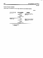
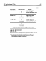
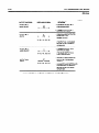
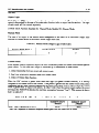
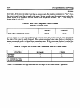
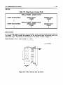
1
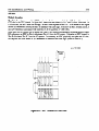
6-39
I/O Specifications and Wiring
GEK-90842
High Speed Counter
IC610MDLllO
The High Speed Counter module (HSC) allows a Series One or Series One Plus PC to monitor and
control a number of process variables (position, velocity, flow rate) that the CPU cannot control due to
timing constraints.
A logical relationship between the counters seven inputs, the preset, and current
value determines the status of its own two external outputs as well as others through CPU user logic.
Figure 6.41 illustrates this concept.
The module can be installed in any of the first 4 I/O slots adjacent to the CPU, and uses 8 I/O and 2
counter references to interface with user logic. Indicators on the front face of the module give output
and count status.
General
Increment (Up) Count
Decrement (Down) Count
Reset/Marker
PIeset value (0 - 9999)
Current Value (0 - 9999)
Two Discrae DC (5 - 24 V)
Current Value (BCD)
< 100 Microseconds Between Pulse
Received and Transition of Output
up/Down counter Inputs
up/DOWn
COMW
specifications
OUtpUtS
Reaction Time
Environmental
Operating Temperature
Humidity, Non-Condensing
Power Consumption from Internal Supply
Pulse Rate
we
Minimum Pulse Width
OFF-
0 to 6o” c
5 to 95 %
70mA@9Vdc
Without Filter < 10 Hz
With Filter < 500 Hz
(Filter selection by thee dip
switbes on module, see page 6-69)
0 to 9999 Binq bled Dhnal(BCD)
25 mS
I
+25@=4
6-41
I/O Specifications and Wiring
GEK-90842
Module Location
The High Speed counter module (HSC) can be installed in any one of the four I/O slots adjacent to the
CPU slot in the CPU chassis. In figure 6.42, these slots are shown (A, B, C and D) for a 5-slot rack. In
a lo-slot rack, the HSC must also occupy 1 of the 4 slots adjacent to the CPU. Also shown in this figure
are the I/O references used by the HSC to intetiace with user logic. Note how an HSC located in Slot A
uses I/O references associated with both Slot A (O-3) and Slot A’ (100-103).
Since each slot in a Series One or Series One Plus PC I/O system corresponds to a special group of eight
I/O references, an HSC in Slot A eliminates Slot A’ from the I/O system. Likewise an HSC located in
Slot B eliminates Slot B’ from the I/O system. In summary, an HSC physically occupies one YO slot,
but requires two slots worth of I/o references to interface with user logic (Refer to table 6.5).
pc-sl -84-QOO 1
/ll-knIIlII
I
I
67
1
57
!
i
ONE
SERIES
47
F&we 6-42. HSC Location in 5-Slot Rack
6-42
I/O Specifications and Wiring
Table 6-5. Number of HSCs vs Discrete I/O Capacity
NUMBER OF HIGH SPEED
COUNTER MODULES IN SYSTEM
REMAINING DISCRETE
I/O CAPACITY
/
seriesone
I
Seri~OnePlUS
112
96
168
152
136
120
104
80
64
48
Interface to Field Devices
A 32 PIN Connector
(Refer to figure 6.43) on the faceplate of the HSC is the interface between the
module and its associated field devices which include:
1. Counting mechanism
encoder).
which controls the Up/Down
counter (typically
a bidirectional
2 . Four digit binary coded decimal (BCD) display of counters current value.
3 . Two 5 to -24 V dc loads under control of tvvo counter outputs.
Zoo0
@CD)-
c
1000
400
100
i-1
RESn
MARKER
BCD)
BCD)
@CD,
40
(BCDI
10
fBCD1
4
@CD)
1
MD)
(+I
(-1 SVDC 2 5- OR
12VDCZlD%
RESFf
(+I
MARKER
5 VDC = 5- OR
12VDCzlo;
1
(-1
DECREMENT
f-1
INCREMENT
COWTER
COWTER
i+b
DECREMENT
(+I INCREMENT
COUNTER
COUPTER
Figure 6143. HSC Connector Pin Definition
In the interestof claritythe specifications for each field device are addressed separately.
incremental
6-43
I/O Specifications and Wiring
GEIL90842
Up/Down Counter Inputs
SPECIF’ICATIONS
RESET INPUT
UP/DOWN INPUT
WEM
Minimum Input
Pulse ‘width
Supply Voltage
OnCuIrent
off Current
On Voltage
Off Voltage
25 nsec
loo nsec
+12 V dc, 10%
<3mA
10 to 15 IILA
<3Vdc
>7Vdc
+12 V dc, 10%
10 to 15 mA
<3mA
UVdc
<3Vdc
OFF r
a40068
I
I
.
.
ON--T
ON
,T
OFF 4
RESET*
COUNT*
Figure 644. Signal Direction
The conditions necessary to increment/decrement,
particular interest when counting in one direction
or reset the counter are described below.
only.
DESIRED ACTION
Incxement Current Count
Decrement Cunent Count
Reset Chent
Count
Increment Input:
Decrement Input:
Reset Input:
CONDITION
Increment Input: (Disabled) - (Enabled)
Deuement Input: Disabled
Reset Input: Disabled
Decrement Inputz (Disabled) - (Knabled)
Increment Input: Disabled
Reset Input: Disabled
Reset Input (Disabled) -- (Enabled)
Increment Input: Disabled or Enabled
Decrement Input: Disabled or Enabled
Disabled,~10VdcBetweenPhsB1andAl
Enabled,<2VdcBetw~nPinsBl
andA1
Disabled,>lOVdcBetweenF5niB2andA2
Enabkd,<2VdcBetweenPinsB2andA2
Disabled,<2VdcBetweenPinsB6andA6
Enabled,~lOVdcBetweeaPinsB6andA6
Figure 6-45. UPlDOWNkESET
Input Circuit
.
This is of
644
I/O Specifications and Wiring
GEK-90842
Encoder Interface 1
Typically an incremental encoder controls the counter through the Up/Down, and Reset Inputs. To
comply with HSC circuitry, the encoder should represent clockwise and counterclockwise movement of
its shaft with two separate pulse trains that increment and decrement the counter. Figures 6.46, 6.47,
and 6.48 illustrate sample connections.
.’
pc-~1-84-0005
WGMSPEEDCou)JrrcI
MWULE
Figure
6-46. Encoder with RESET/MARKER Option
Resetting Counter Once Der Revolution
_
of Encoder Shaft
-
a
Figure 64% Encoder with RESET Option in Series with Home Limit Switch Such That
Counter is Reset When Both Home Limit Switch and RESET/MARKER Pulse
are Enabled
I/O Specifications and Wiring
6-45
GEL90842
PHOTO LLECTfBC CELL’
RESET
COUNTER
OECREMENT
COUNTER
HCREMENT
COUNTER
Figure 6-48. Encoder With Limit Switch Resetting Counter and Photoelectric Cell Inhibiting
the Counter Operation
L/O Specifications and Wiring
6-46
GEE90842
Binary Coded Decimal (BCD) Output
To view the counter current value, a four digit BCD (sink/source)
output is provided.
SPECIFICATIONS
RATING
ITEM
0uTPuTPoLARrN
SOURCE MODE
Supply Voltage
Allowable Ripple
cumnt CoI3sumption
Output Voltage
SINK MODE
Output Voltage
1: Optoisolator OFF
0: Ojmisolator ON
See Sample Circuit Below
12 V dc + 10%
< 3%
< 25 mA
6V&
at 0.4 mA
5Vdc
5%
< 1%
< 10 mA
3.5 v dc
at 0.1 mA
0.4 v dc @ 2 IIA
0.1 v dc @ 3 mA
a40070
SVDC
OR
r2vrlC
(SOURCE)
IOKfi
I
VOLTAGE
Figure 649. Sample BCD Output Circuit
I/O Specifications and Wiring
6-47
GEK-90842
Figure 6.50 illustrates the connections necessary to use an external BCD Display. For a source type
output the 5 V or 12 V supply is required.
SENSE OF OUTPUT:
SENSE OF OUTPUT:
(1) Optoisolator OFF
(0) Optoisolator ON
PCFOUR DIGIT
BCD DISPLAY
SAMPLE ClRCutT
I
t
OPTOISOLATOR
’
II
a
II
l-
V.
Figure 640.
5-12 VDC
BCD Output Wiring Diagram
UNITS
’
I/O Specifkations and Wiring
Counter Output
The HSC has two discrete outputs that can be controlled from ladder logic or by the relationship
between the present and current value of the counter.
SPECIFICATIONS
_
ITEM
RATING
Type
NPN Transistor, open collector, sinking
Voltage Range
Peak Voltage
Cumznt Range
5 to 24 V dc
< 45 V dc
> 0.3 A
A typical wiring schematic
to field devices and a sample circuit are shown in figure 6.51.
HK3H SPEED COUNTER MODULE
B
USER LOADS
+v
5-24VDC
Figure 641.
User Load Wiring Diagram
(>=<)
i-
I/O Specifications and Wiring
-c
6149
GEK-90842
Interface to User Logic
Eight I/O and two counter functions interface the HSC to user logic. The specificreferences associated
with these functions depend upon the location of the module in the CPU rack. Figure 6.52 illustrates
how these references comspond to the modules location.
I
1
’
couNTmfuwTmH
I
;
I
muNlm#RmNcm
I
I
I
I
;
,
’
,106I
PRESETVALUE
I107
' 105 , 103 I 101 I
,
,
’
I
’
mwr~~wcE8
I
I
I
I
m?urFwcrmu
I
I
>PRESETVALlE
’
‘30
-fRESOVMUE
I31
,
<PREsnvALlJE
' 32
CARRvmmRow
'I33
I
I
OvlcvTnmcnm
I
104,
t
smcuRRENTvALuf
I
‘20
omPulNO.l~SflECf'
omPuTMo.2sTATE
O~T~TNO.~M~~ESEECT'
'
’
I
I
’
1
I
I
1
1
22
,'2
IO2
,
, 23
113
I03
,
I
'
I
,
I
,
1
i
1130,
1
I
‘00
'01
I
ok!mAFElrmu,
I
100,
,‘O
(11
I2l
1
I
oiJlPul~.1S1AtE
102,
I
I
'
120,
110,
100;
131 I
132,
121,
122,
111,
112,
101 '
102 I
133'
123)
113'
103I
I
I
l
’
Figure 642. I/O and Counter Function Reference Chart
640
I/O Specifications and Wiring
Interface Function Definition
Shown below is the definition and user logic symbol for each interface function.
a42645
5
5
SET CURRENT VALUE
X+
v+
WHEN COUNTER X Is ENABLED,
CURRENT COUNT IS SET TO A
VALUE OF Y
O--r7
x: loo, 102,104,106
Y:O-9999
PRESET VALUE
4-l
CNT
X+
Y+
x: 101,103,105,107
Y:O-9999
l
l
X - Counter Reference
Y=VaMRarrge
WHEN COUNTER X IS ENABLED,
PRESET VALUE OF COUNTER
ISSETTOY
641
I/O Specificationsand Wiring
GEK-90842
a42646
PUT FUNCnQbls
> PRESET VALUE*
ENABLED WHEN CURRENT
VALUE OF COUNTER IS
GREATER THAN ITS PRESET VALUE
l
x: 00, 10,20,30
I: PRESET VALUE*
l
,1,
ENABLED WHEN CURRENT
VALUE OFCOUNTER IS
EQUAL TO ITS PRESET VALUE
x: 01, 11,21,31
ENABLED WHEN CURRENT
VALUE OF COUNTER IS
LESS THAN ITS PRESET VALUE
< PRESET VALUE+ *
X: 02, 12,22,32
CARRY / BORROW
,rt+
l
X: 03, 13,23,33
l
0001 - 0000 - 9999 (Decrement Rollover)
9999 - 0000 - 0001 (Increment Rollover)
0001 - 0000 - 0001
9998 - 9999 - 9998
(Increment Current Count) - (Extemalty Reset Counter) - (Decrement Current Count)
(Decrement Current Count) - (Externally Reset Counter) - (Increment or Decrement Current Count)
1.
2.
3.
4.
5.
6.
l
Enabied when current value of the counter undergoes one of the six sequences
described beiow :
l
The status of these input functions is given to the CPU once per scan. Therefore, if a
particularcanditbn is true for less than the scan time of the user bgic, its associated
Input function woukl not be enabled in the user program.
I/O Specifications and Wiring
GEK-90842
a42647
J
QEEMmQN’
USER
OUTPUT NO. 1
MODE SELECT
. IF DISABLED OUTPUT NO. 1
IS IN MANUAL MODE
. IF ENABLED OUTPUT NO. 1
IS IN COUNTER MODE
OUTPUT NO. 1
STATE
l
l
X: 103, 113, 123,133
. IF ENABLED OUTPUT NO. 2
IS IN COUNTER MODE.
l
,K,
X: 102,112, 122, 132
l
IN COUNTER MODE DETERMINES
IF OUTPUT NO. 1 IS ENABLED
BEFORE OR AmER PRESET
IS REACHED
. IF DISABLED OUTPUT NO. 2
IS IN MANUAL MODE
OUTPUT NO. 2
MODE SELECT
OUTPUT NO. 2
STATE
IN MANUAL MODE OPERATES
OUlWTNO. 1 AS
NORMAL OUTPUT
l
IN MANUAL MODE OPERATES
OUTPUT NO. 2 AS NORMAL
OUTPUT
IN COUNTER MODE DETERMINES
IF OUTPUT NO. 2 IS ENABLED
BEFORE OR ARER PRESET
IS REACHED
For further description on the operation of outputs, refer to Output Logic Section.
I/O Specifications and Wiring
643
GEK-90842
Ouptut Logic
Each of the two HSC outputs operate in either the manual or counter mode. The operating mode of each
output is determined by the state of its mode select function (refer to output function section). The logic
of each mode will be covered separately.
If Mode Select Function
Disabled (0): Manual Mode, Enabled (1): Counter Mode.
Manual Mode
The state of an output in the manual mode corresponds to the status of its associated
Function as shown below in the manual mode output truth table.
Output State
Table 6-6. Manual Mode Output Logic Truth Table
I
OUTPUT MODE SELECT
I
0
0
OUTPUT STATE
I
0
1
OUTPUT
I
0
1
l
Counter Mode
In the counter mode of operation outputs can react immediately when the current count reaches specific
preset values. In this mode each output is controlled by a combination of three ‘factors.
1. Initial relationship
between preset and current count.
2. Real time relationship
3. Status
of
between preset and current count.
Output State function.
When the HSC receives a preset value from user logic (via preset counter function), it is initially
compared to the current value of the counter. If the preset is-greater than the current count in this initial
comparison the real time comparison *2between the preset and current count is “true” when the current
count is greater than or equal to the preset. In other words when the current count reaches the preset
moving in the POSITIVE direction the real time comparison becomes “true”.
This concept is shown
below in table 6.7.
Table 6-7. Real Time Comparison Table for Preset Initially > Current Count
/
REAL TIME COMPARISON STATUS
CURRENT COUNT
< PRESET
CURRENT COUNT
-> PRESET
FALSE
TRUE
*Real Time compariston = continuous comparison between preset value and cummt value of cutmter.
1
6-54
I/O Specifkations and Wiring
GEK-90842
Conversely, if the preset is kGtially less than the current count, the real time comparison is “true” when
the current count is less than or equal to the preset. In other words, when the current count reaches the
preset moving in the negative direction the real time comparison becomes “true”.
This concept is
shown below in table 6.8.
Table 6-8. Real Time Comparison Table for Preset
Initially c Current Count
I
I REAL TIME COMPARISON STATUS
CURRENTCOUNT
> PRESET
FALSE
I
I
CURRENT COUNT
< PRESET
I
I
TRUE
I
Once the status of the real time comparison between the preset and current count has been determined,
the status of the output is easily obtained. If the outputs associated output state function is disabled its
status corresponds directly to the real time comparison status. If the output state function is enabled the
output’s status is the inverse of the real time comparison status. This concept is shown in table 6.9.
Table 6.9. Output State vs Real Time Comparison Status in Counter Mode
OUTPUT STATE
FUNCTION
I
I
DISABLED
ENABLED
1: OUTPUT ENABLED
0: OUTPUT DISABLED
Table 6.10 summarizes
I
I
I
REAL TIME COMPARISON
IS FALSE
0
1
REAL TIME COMPARISON
ISTRUE
I
1
0
-
I
the logic associated with an output in the counter mode of operation.
I
I
I
Ii0 Specifications and Wiring
6-55
GEK-90842
Table 640. Output Logic in Counter Mode
INITMLLY PRESET > CURREW
OUTPUT STATE FUNCTION
0
1
COUNT
cuRRENTcOuNT
< PRESET
0
CURRENT COUNT
> PRESET
1
1
0
INITMLLY PRESET < CURRENT COUNT
OUTFWT STATE FUNCTION
0
1
cuRRENTcOuNT
> PRESET
0
1
CURRENT COUNT
< PRESET
1
0
Filter Selection
In some electrical noisy environments it may be necessary to filter out noise through filters available on
the module.
The HSC provides this capability on the incremental count, decremental count, and
reset/inarker inputs. The location of these switches on the module is shown in figure 6.53.
Sense of switch: OPEN - Filter Disabled (< 10 Khz)
CLOSED - Filter Enabled (C 500 Hz)
Figure 643. Filter Selection with Dip Switch