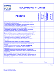
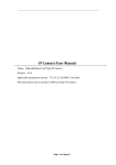
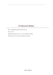
1
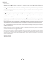
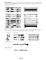
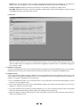
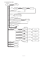
User's Manual
DIGAN2.30
2 x 30 BAND
DIGITAL EQUALIZER
R
LTO
www.altoproaudio.com
Version 1.2 May 2006
English
Fuse
SAFETY RELATED SYMBOLS
To prevent fire and damage to the product, use only
the recommended fuse type as indicated in this
manual. Do not short-circuit the fuse holder. Before
replacing the fuse, make sure that the product is
OFF and disconnected from the AC outlet.
CAUTION
RISK OF ELECTRIC SHOCK
DO NOT OPEN
This symbol, wherever used, alerts you to the presence of un-insulated and dangerous voltages within the product enclosure. These are voltages that
may be sufficient to constitute the risk of electric
shock or death.
Protective Ground
Before turning the product ON, make sure that it is
connected to Ground. This is to prevent the risk of
electric shock.
This symbol, wherever used, alerts you to important operating and maintenance instructions.
Please read.
Never cut internal or external Ground wires. Likewise,
never remove Ground wiring from the Protective
Ground Terminal.
Protective Ground Terminal
Operating Conditions
AC mains (Alternating Current)
Always install in accordance with the manufacturer's
instructions.
Hazardous Live Terminal
ON:
To avoid the risk of electric shock and damage, do
not subject this product to any liquid/rain or moisture.
Do not use this product when in close proximity to
water.
Denotes the product is turned on.
OFF: Denotes the product is turned off.
WARNING
Do not install this product near any direct heat source.
Describes precautions that should be observed to
prevent the possibility of death or injury to the user.
Do not block areas of ventilation. Failure to do so
could result in fire.
CAUTION
Keep product away from naked flames.
Describes precautions that should be observed to
prevent damage to the product.
IMPORTANT SAFETY INSTRUCTIONS
Read these instructions
Disposing of this product should not be
placed in municipal waste and should be
Separate collection.
Follow all instructions
Keep these instructions. Do not discard.
Heed all warnings.
WARNING
Only use attachments/accessories specified by the
manufacturer.
Power Supply
Ensure that the mains source voltage (AC outlet)
matches the voltage rating of the product. Failure
to do so could result in damage to the product and
possibly the user.
Power Cord and Plug
Do not tamper with the power cord or plug. These are
designed for your safety.
Unplug the product before electrical storms occur
and when unused for long periods of time to reduce
the risk of electric shock or fire.
Do not remove Ground connections!
External Connection
Protect the power cord and plug from any physical
stress to avoid risk of electric shock.
If the plug does not fit your AC outlet seek advice from
a qualified electrician.
Always use proper ready-made insulated mains
cabling (power cord). Failure to do so could result
in shock/death or fire. If in doubt, seek advice from
a registered electrician.
Do not place heavy objects on the power cord. This
could cause electric shock or fire.
Cleaning
When required, either blow off dust from the product
or use a dry cloth.
Do Not Remove Any Covers
Within the product are areas where high voltages
may present. To reduce the risk of electric shock do
not remove any covers unless the AC mains power
cord is removed.
Do not use any solvents such as Benzol or Alcohol.
For safety, keep product clean and free from dust.
Servicing
Covers should be removed by qualified service
personnel only.
No user serviceable parts inside.
Refer all servicing to qualified service personnel only.
Do not perform any servicing other than those instructions contained within the User's Manual.
1
PREFACE
Dear Customer:
Thanks for choosing
researches.
For our
LTO DIGAN2.30 and thanks for choosing one of the results of
LTO AUDIO TEAM job and
LTO AUDIO TEAM, music and sound are more than a job...are first of all passion and let us say our obsession!
We have been designing professional audio products for a long time in cooperation with some of the major brands in
the world in the audio field.
The LTO line presents unparalleled analogue and digital products made by Musicians for Musicians in our R & D
centers in Italy, Netherlands, United Kingdom and Taiwan. The core of our digital audio products is a sophisticated
DSP (Digital Sound Processor) and a large range of state of the art algorithms, which have been developed by our
software team for many years.
Because we are convinced you are the most important member of LTO AUDIO TEAM and the one confirming the
quality of our job, we would like to share with you our work and our dreams, paying attention to your suggestions and
your comments.
Following this idea we create our products and we will create the new ones! From our side, we guarantee you and we
will guarantee you also in future the best quality, the best fruits of our continuous researches and the best prices.
Our LTO DIGAN2.30 is the result of many hours of listening and tests involving common people, area experts,
musicians and technicians.
Besides, we offer you a number of factory EQ curves that we collected and transformed in presets now available in
our small, efficient and easy to use LTO DIGAN2.30.
Nothing else to add, but that we would like to thank all the people that made the LTO DIGAN2.30 a reality available
to our customers, and thank our designers and all the LTO staff, people who make possible the realization of products
containing our idea of music and sound and are ready to support you, our customers, in the best way, conscious that
you are our best richness.
Thank you very much
LTO AUDIO TEAM
2
TABLE OF CONTENTS
1. INTRODUCTION....................................................................................................................................4
2. FEATURES.............................................................................................................................................4
3. CONTROL ELEMENTS.........................................................................................................................4
3.1 The Front Panel
3.2 The Rear Panel
4. INSTALLATION AND CONNECTION.....................................................................................................5
4.1Mains Connection
4.2Audio Connection
5. OPERATION OVERVIEW......................................................................................................................7
5.1 Modify the parameters
5.2 Store preset
5.3 Bypass mode
5.4 Link mode
5.5 Select preset fast
5.6 Demo mode
5.7 Audition mode
5.8 Delay mode
5.9 Hi-pass/Low-pass mode
6. SYSTEM SETTING ................................................................................................................................8
6.1 Setup mode
6.2 Reset Mode
7. REMOTE CONTROL .............................................................................................................................9
7.1 Software installation
7.2 First steps with the PC Editor
7.3 Upload or Download
7.4 Update system
8. OPERATION FLOW CHART ................................................................................................................11
9. TECHNICAL SPECIFICATION.............................................................................................................12
10. WARRANTY..........................................................................................................................................13
3
1. INTRODUCTION
Purchasing LTO DIGAN2.30, you purchase a very powerful digital equalizer, easy to use and contain in a very
efficient single unit rack package. Our new DIGAN2.30 is a versatile and very powerful parametric & graphic equalizer.
It will provide precise audio signal control to fixed sound installation, live performance and studio applications. Thanks
to the use of selected and expensive components, the performance of DIGAN2.30 are worth much more than its price.
2. FEATURES
Mountable in one standard unit rack 19".
Stereo 30 bands graphic parametric equalizer.
80 presets: 30 factory presets and 50 user-programmable presets.
32 24 bit DSP processor with 48kHz sampling rate.
Stereo channels processing with or without link control.
30 EQ bands per channel, spanning 25Hz ~ 20kHz in 1/3 octave increments.
+/-12dB boost / cut for 30 frequency bands.
Master volume and individual volume control.
Bypass function.
Signal and Clipper LED.
Easy operating with PC editor.
"Lock" function to prevent accidental reprogramming.
1/4" TRS and balanced XLR connectors available.
3. CONTROL ELEMENTS
3.1 The Front Panel
(8)(7) (6) (7) (8)
CLIP
CLIP
SIGNAL
SIGNAL
BYPASS
POWER
LINK
STORE
DIGAN2.30
R
LTO
Digital Equalizer
25
(10)
31 . 5
40
50
63
80
100
125
160 200 250
315 400 500 630 800
1K
1 . 25K 1 . 6K
2K 2 . 5K 3 . 15K 4K
5K 6 . 3K 8K
10K 12 . 5K 16K 20K
(9)
(3) (4)
25
31 . 5
40
50
63
80
100
125
160 200 250
315 400 500 630 800
(5) (2) (1)
1K
1 . 25K 1 . 6K
2K 2 . 5K 3 . 15K 4K
5K 6 . 3K 8K
(9)
10K 12 . 5K 16K 20K
(10)
1. POWER switch
This switch is used to turn the main power ON or OFF.
2. STORE key
This key is used to store the user's presets.
3. BYPASS key
This key is used to bypass the process, sending the input signals to the DIGAN2.30 outputs directly.
When the DIGAN2.30 is in this mode, the BYPASS LED will be on.
4. LINK(Exit) key
This key is used to link the two stereo channels or exit from menu.
5. Up/Down key
These keys are used to select the preset and modify the parameter's value.
6. LED display
This LED display shows the selected preset number or the parameter's value.
7. CLIP LED
This LED indicates when the input signal is too high.
8. SIGNAL LED
This LED indicates when there is signal present in this unit.
9. Band keys
These keys are used to select the frequency band that you need to modify its gain value.
10. Mounting ear
This detachable mounting ear is used for your convenient installation in a standard 19" rack.
4
3.2 The Rear Panel
TIP/PIN 2
RING/PIN 3
SLEEVE/PIN 1
CH.B
OUTPUT
CH.A
TIP/PIN 2
RING/PIN 3
SLEEVE/PIN 1
INPUT
PUSH
CH.B
PUSH
CH.A
USB
DIGITAL OUTPUT
SERIAL PORT
SPDIF
POWER
9 VAC
MODEL
SERIAL
Rated Power Consumption 15W
(15)
(14)
(13)
(12) (11)
11. DIGITAL OUTPUT SPDIF
This jack is used to output the digital signal to digital record device using a standard RCA cable.
12. USB SERIAL PORT
This serial port is used to connect the unit to PC with the supplied transmission line.
13. INPUT
These are XLR and 1/4" TRS balanced connectors, which are used to connect devices such as the channel
inserts of a mixing console.
14. OUTPUT
These are XLR and 1/4" TRS balanced connectors, which are used to connect sources such as the channel
inserts of a mixing console or power amplifier's input.
15. POWER INLET
This jack is used to connect the AC power supply with the supplied 9V AC adapter.
4. INSTALLATION & CONNECTION
4.1 Mains Connection
The 9VAC adapter that meets all the international safety regulations is supplied with your LTO DIGAN2.30.
Before power on the DIGAN2.30, please make sure all connections have been made correctly and the volume
controls of the amplifier or mixer are turned down.
4.2 Audio Connection
Both XLR and 1/4 " TRS connectors are available on your LTO DIGAN2.30. In this way you can interface your
DIGAN2.30 in several different ways without experiencing any noise or signal loss. You can use your DIGAN2.30
with single instruments using the mixer's main insert or on "in-line" between a mixing console's output and a power
amplifier.
- Wiring Configuration
Either the 1/4" TRS phone jack or XLR connector can be wired in balanced and unbalanced modes, which will
be determined by the actual application status, please wire your system as the following wiring examples:
For 1/4" Phone jack
+
+
-
Tip
Ring
+
Tip
Tip
Ring
Sleeve
Sleeve
TS Type Unbalanced
Sleeve
TRS Type Balanced
TRS Type Unbalanced
For XLR connector
Pin2 (+)
Pin3 (-)
(Linked to Pin1 manually,
Pin2 (+)
Pin3 (-)
)
Pin1 ( )
Pin1 ( )
XLR Type Unbalanced
XLR Type Balanced
5
- In-line Connection
For these applications the LTO DIGAN2.30 Parametric/Graphic Equalizer provides 1/4" TRS and XLR
connectors to easily interface with most professional audio devices. Follow the configuration examples below
for your particular connection.
Balanced
Tip
Ring
Sleeve
SLEEVE RING TIP
TIP RING SLEEVE
1
2
1
2
3
3
Tip
Ring
1
2
3
3
3
1
1
2
2
1
3
2
TIP RING SLEEVE
Tip
Ring
Sleeve
Sleeve
Unbalanced
1
Tip
Ring
3
2
1
2
3
Sleeve
TIP RING SLEEVE
Tip
1
1
2
3
3
2
Sleeve
1
TIP SLEEVE
2
3
1
2
3
Cent r e
Screen
Tip
TIP SLEEVE
Tip
Sleeve
SLEEVE TIP
Sleeve
Tip
Ring
TIP RING SLEEVE
SLEEVE RING TIP
Tip
Ring
Sleeve
Sleeve
Tip
Cent r e
Sleeve
Screen
Tip
Ring
Centre
Sleeve
Screen
TIP SLEEVE
TIP RING SLEEVE
3
3
1
1
1
2
2
2
1
2
3
3
- Insert Points Connection
If you are connecting to a mixing console's main inserts, you may have a single TRS jack for Send and
Return, in this case, use an insert "Y" cable that configured like the examples below.
1/4" TRS insert
Insert Leads
Send
Return
SLEEVE TIP
TIP RING SLEEVE
Tip
Ring
Sleeve
Tip (Send)
Sleeve
Tip (Return)
Sleeve
SLEEVE RING TIP
1
2 (Send)
1
3
2
2
Tip
Ring
Sleeve
3
1
TIP RING SLEEVE
3
1
2 (Return)
3
Ring
Tip
Sleeve
Tip
Ring
Sleeve
TIP RING SLEEVE
Centre (Send)
Screen
Centre (Return)
Screen
- USB Connection
- SPDIF Connection
6
5. OPERATION OVERVIEW
Switching on the DIGAN2.30, the last selected preset and settings will be loaded, the number of last preset will appear
on the display.
5.1 Modify the parameters
Select one of the presets using UP/DOWN keys.
Select the frequency band that you want to modify its gain value.
Using UP/DOWN keys to modify its gain value.
Note: You can select as many as bands that you wish to change, once the indicators of selected bands are
all blinking, then you can adjust the gain value of all these selected bands simultaneously via UP/DOWN keys.
when Release Edit Group (see 6.1) is set ON, if you want to modify the others frequency bands, select it, and
adjust the gain value via UP/DOWN keys separately, it doesn't affect the frequency bands, which has been
selected and modified before. On the other hand, if you set Release Edit Group OFF, all the selected frequency
bands, which include the modified and unmodified will be adjusted together at the same time via UP/DOWN keys.
5.2 Store preset
Press STORE key after you finish the change.
Using UP/DOWN keys to select between preset 30-79 (user preset).
Press STORE again to store the new preset.
If you don't want to save your new preset, press LINK key to exit from this menu.
Note: Factory preset (0-29) can used normally, temporarily modified, but can't be cancelled, overwritten or permanently
modified. User preset (30-79) can be programmed by users and used to save your own settings.
5.3 Bypass mode
Press BYPASS key to enter bypass mode, the bypass indicator will light up.
Press BYPASS key again to exit bypass mode, the bypass indicator will go out.
Note: In bypass mode, the output signal has not been processed, so this function will be quite useful for you
to compare the processed signal with unprocessed signal.
5.4 Link mode
Press LINK key to enter link mode, the link indicator will light up.
Press LINK key again to exit link mode, the link indicator will go out.
Note: In link mode, these two channels are "linked together", so the changes will be simultaneously applied to
both channels. Also, the LINK key has "Exit" function.
5.5 Select preset fast
Press and hold DOWN key, then press UP key, the current preset will change to 0, the preset will increase 10
with each press of UP key again.
Press and hold UP key, then press DOWN key, the current preset will change to 0, the preset will decrease 10
with each press of DOWN key again.
Release DOWN or UP key, your selected preset will be loaded (for example preset 30), then use UP/DOWN
keys to select the right preset you want (for example preset 32).
5.6 Demo mode
Press and hold LINK key, then press UP to enter demo mode, all presets will be displayed one by one. The bypass
indicator will be ON in demo mode, you can press LINK to exit from demo mode.
5.7 Audition mode
Press and hold LINK key, then press DOWN to enter audition mode. In audition mode, you can adjust the demo's
interval time (1-25) using UP or DOWN keys. The number is larger, and the interval of demo is longer. Also you
can select the presets that you wish to demo by pressing corresponding bands. Press LINK key to exit.
Note: The audition mode will be usable only when Audition Auto (see 6.1) is set ON.
5.8 Delay mode
Press 20k of left channel and BYPASS at the same to enter delay mode. Press any a band of 25, 31 and 40 on left
channel to select the left channel, press any a band of 40, 50 and 62 on right channel to select the right channel.
Then, you can press UP or DOWN keys to adjust the delay time of either channel. Press LINK key to exit.
5.9 Level Control
Press and hold the key of 16k (CH.A), then press 20k (CH.A), it will allow you to adjust the level of CH A via
UP/DOWN keys. If you want to adjust the level of CH B, please press and hold the key of 25Hz (CH. B), then
Press the key of 31.5Hz(CH. B), it will allow you to adjust the level of CH B via UP/DOWN keys.
7
5.10 Hi-pass/Low-pass mode
Press 16k of left channel and BYPASS key to enter hi-pass/low-pass mode. The adjustable parameter as following
table.
Ch. A
Ch. B
Press:
25 Hz (Ch. A)
31.5 Hz (Ch. A)
40 Hz (Ch. A)
50 Hz (Ch. A)
Result:
Ch. A_LP_Slope Down
Ch. A_LP_Slope Up
Ch. A_LP_Freq Down
Ch. A_LP_Freq Up
10K Hz (Ch. A)
12.5K Hz (Ch. A)
16K Hz (Ch. A)
20K Hz (Ch. A)
Ch. A_HP_Slope Down
Ch. A_HP_Slope Up
Ch. A_HP_Freq Down
Ch. A_HP_Freq Up
25 Hz (Ch. B)
31.5 Hz (Ch. B)
Ch. B_LP_Slope Down
Ch. B_LP_Slope Up
40 Hz (Ch. B)
50 Hz (Ch. B)
10K Hz (Ch. B)
12.5K Hz (Ch. B)
16K Hz (Ch. B)
20K Hz (Ch. B)
Ch. B_LP_Freq Down
Ch. B_LP_Freq Up
Ch. B_HP_Slope Down
Ch. B_HP_Slope Up
Ch. B_HP_Freq Down
Ch. B_HP_Freq Up
6. SYSTEM SETTING
6.1 Setup mode
When power on this unit, the front panel will show DIAGAN2.30 for a few seconds, press STORE key timely before
the show is finished to enter setup mode. It concludes Master Level, Release Edit Group, Audition Auto, Edit Time
Out and Lock Key settings. In setup mode, you can use STORE key to cycle above settings, then use UP or
DOWN key to change the settings.
- Master Level
This is the overall output level, the output range is +/-6dB. (It is different from preset level, and it will not change
as the change of preset.)
- Release Edit Group
ON: It allows you to choose as many as frequency bands to modify their gain values simultaneously.
OFF: You can select one frequency band at a time.
- Audition Auto
ON: It allows you to modify the parameters in audition mode.
OFF: It doesn't allow you to modify the parameters in audition mode.
- Edit Time Out
ON: If you don't operate the unit for 60 seconds, the unit will cancel your selection and settings that you haven't
stored, and reload the settings before storing the preset.
OFF: Disable the "Auto cancel" function.
- Lock: avoid unauthorized tampering.
ON: When power on the unit, the unit can not be operated. If you press any of the buttons, the LED display will
show "Lo" to indicate that the unit is locked.
OFF: Cancel the function of locking.
6.2 Reset Mode
When power on this unit, the front panel will show DIAGAN2.30 for a few seconds, press and hold UP then press
DOWN key timely to enter reset mode. Now, all the stored presets will be reset to defaults.
8
7. REMOTE CONTROL
To operate this unit while connected to a PC, you need to download a Windows compatible DIGAN Editor program from
our website. To get a copy, please go to http://www.altoproaudio.com/html/download.php
IMPORTANT!
In remote control, all the controls on front panel are disabled.
7.1 Software installation
a. Install Digan Editor program: run DiganEditor100.exe (latest version may differ), then select the folder where
the program is installed and press NEXT, select the program location and press NEXT (it is suggested to use
default setting), now verify your setup information and press NEXT to finish your last step.
b. Install USB driver: run PL-2303 Driver Installer.exe, then press N for next step, at last finish your installation
and exit.
7.2 First steps with the PC Editor
With the DIGAN2.30 unit powered up and connected to the USB port on your PC, run the PC Editor program
by selecting the DIGAN EDITOR icon in the Windows PROGRAMS menu. Select NEW from the FILE menu,
then DIGAN2.30 and click OK, now select ON LINE from ACTION menu and the PC will scan its USB port to
verify the DIGAN2.30 unit is correctly connected. The NETWORK SCAN window should show the system
status (CONNECTED or DISCONNECTED). See following picture.
a. Main menu
- Load Preset: This function allows to load one of the 80 available presets, the first 30 (0-29) presets are factory
configured presets, the presets (30-79) are user's programmable presets.
- Save Preset: You can store the new preset into one of user presets (30-79).
- Bypass: When you click BYPASS, only Load and Save preset functions are activated in the main menu, all the
rest functions are disabled. The output signal is exactly same as the input signal.
- LINK: When you click LINK, you can operate both channels just at one operation.
9
- DELAY: You can use Up/Down arrow or drag the speaker to adjust both channel's delay time, or together by
LINK function, the LED display on the front panel of DIGAN2.30 will show the channel's delay time.
- LP/HP Freq/Slope: Adjust the frequency and slope of LP/HP filter or together by LINK function.
- VOLUME: Adjust both channel's volume or together by LINK function, also the LED display on the front panel
of DIGAN2.30 will show the channel's volume.
b. EQ menu
When you go to the EQ menu, the PC will display above picture. You can adjust each band's gain value, if this
unit is in LINK function, the change on channel A will be applied to channel B also. The adjustable range goes
from 12dB to +12dB.
7.3 Upload or Download
You can use UPLOAD from FILE menu to upload all saved user presets (30-79) from DIGAN2.30 unit to your computer.
DOWNLOAD from FILE menu will download all saved user presets in your computer to DIGAN2.30 unit.
7.4 Update system
If the version of Digan Editor program is different from that in DIGAN2.30 unit, the window will show error to ask
you to update your system in DIGAN2.30 unit, or your DIGAN2.30 can't be recognized by your computer. To
update your system in DIGAN2.30, do the following:
a. Turn on DIGAN2.30 while it is not connected with PC, then press 20k of channel B and BYPASS key at the
same time to enter Update mode.
b. Now connect DIGAN2.30 to PC and run DIGAN Editor software, the window will ask whether you are sure to
update your system, press OK to start.
c. If you have selected a wrong model (for example DIGAN2.14), you have to reselect the right model. If the updating
process is terminated abnormally, please restart your updating from the beginning.
d. While this update is finished, firstly, disconnect the main power, and then connect to the main power again to
restart your DIGAN2.30 unit.
10
8. Operation Flow Chart
Start
UP/DOWN
Preset
0~79
STORE
LED Display
(Blinking)
UP/DOWN
Preset user
location 30~79
STORE
Save Preset
LINK(EXIT)
LINK(EXIT)
LINK(EXIT)
Copy Channel A to Channel B
(Mirror A and Channel B key disable)
LINK(EXIT)
BAND SELECT
Band select 0~29: Channel A
Band select 30~59: Channel B
Adjust Gain Value
LINK(EXIT)
LINK(EXIT)
BYPASS
Bypass
BYPASS
SETUP
Setup
ChA 25Hz
Master Level
UP/DOWN
-6dB~+6dB
STORE
ChA 31Hz
Release Edit Group
UP/DOWN
On/Off
STORE
ChA 40Hz
Audition Auto
UP/DOWN
On/Off
STORE
ChA 50Hz
Edit Time Out
UP/DOWN
On/Off
STORE
ChA 62Hz
UP/DOWN
Lock
RESET
UPDATE
HARDWARE
TEST
Reset
STORE
Update
Hardware Test
11
On/Off
9. TECHNICAL SPECIFICATION
System parametric
Filter
Band
Bandwidth
THD+N%
Signal to noise ratio
Input gain
Output gain
Delay line
Preset
High pass filter
2 30 bands,1/3 octave
20Hz-20kHz
<0.015%, Analog In to Analog Out
>90dB A-Weighted, Analog In to Analog Out
+/-12dB
+/-6dB
255ms
Factory preset: 30 , User preset: 50
Freq: 25Hz-25kHz step 1/3 oct
Slope: bypass , -6dB/oct, 12dB/oct
Freq: 20Hz-20kHz step 1/3 oct
Slope: bypass, -6dB/oct, 12dB/oct
Balanced XLR and 1/4" TRS connectors
Balanced > 50Kohm, Unbalanced > 25Kohm
Maximum Input Level : +10dBu
Low pass filter
Input section
Inputs
Input impedance
Input level
Output section
Outputs
Output impedance
Output level
USB serial port
Power supply
(AC/AC adapter)
Physical
Balanced XLR, 1/4" TRS and SPDIF connectors
Balanced 120ohm, Unbalanced > 60ohm
Maximum Output Level : +10dBu
USB1.1
9 Volt AC Power Transformer
8W
483 150 44mm
4.8 lbs(2.15kg)
Input voltage
Power consumption
Dimension (W D H)
Net weight
12
10. WARRANTY
1. WARRANTY REGISTRATION CARD
To obtain Warranty Service, the buyer should first fill out and return the enclosed Warranty Registration Card within
10 days of the Purchase Date.
All the information presented in this Warranty Registration Card gives the manufacturer a better understanding of
the sales status, so as to purport a more effective and efficient after-sales warranty service.
Please fill out all the information carefully and genuinely, miswriting or absence of this card will void your warranty
service.
2. RETURN NOTICE
2.1 In case of return for any warranty service, please make sure that the product is well packed in its original shipping
carton, and it can protect your unit from any other extra damage.
2.2 Please provide a copy of your sales receipt or other proof of purchase with the returned machine, and give detail
information about your return address and contact telephone number.
2.3 A brief description of the defect will be appreciated.
2.4 Please prepay all the costs involved in the return shipping, handling and insurance.
3. TERMS AND CONDITIONS
3.1
LTO warrants that this product will be free from any defects in materials and/or workmanship for a period
of 1 year from the purchase date if you have completed the Warranty Registration Card in time.
3.2 The warranty service is only available to the original consumer, who purchased this product directly from the
retail dealer, and it can not be transferred.
3.3 During the warranty service, LTO may repair or replace this product at its own option at no charge to you for
parts or for labor in accordance with the right side of this limited warranty.
3.4 This warranty does not apply to the damages to this product that occurred as the following conditions:
Instead of operating in accordance with the user's manual thoroughly, any abuse or misuse of this product.
Normal tear and wear.
The product has been altered or modified in any way.
Damage which may have been caused either directly or indirectly by another product / force / etc.
Abnormal service or repairing by anyone other than the qualified personnel or technician.
And in such cases, all the expenses will be charged to the buyer.
3.5 In no event shall LTO be liable for any incidental or consequential damages. Some states do not allow the exclusion or limitation of incidental or consequential damages, so the above exclusion or limitation may not apply to you.
3.6 This warranty gives you the specific rights, and these rights are compatible with the state laws, you may also
have other statutory rights that may vary from state to state.
13
SEIKAKU TECHNICAL GROUP LIMITED
No. 1, Lane 17, Sec. 2, Han Shi West Road, Taichung 40151, Taiwan
http://www.altoproaudio.com Tel: 886-4-22313737
email: [email protected] Fax: 886-4-22346757
All rights reserved to ALTO. All features and content might be changed
without prior notice. Any photocopy, translation, or reproduction of part of this
manual without written permission is forbidden. Copyright c 2006 SEIKAKU GROUP
NF02070-1.2