1
rev 1.01 / 2011 09 07
LDD-2U laser diode controller
User manual
Overview
LDD-2U laser diode controller consists of LDD-series laser diode driver,
none/one/two temperature controllers, user interface and 19-inch rack mounted
coverage case.
Module's input is 110VAC or 230VAC mains, module's outputs are laser diode
connections and Peltiers connections. User interface is dual (front panel interface
and RS-232 interface).
Module is designed for CW operations. In the spite of this the low speed
modulation of the output is available (parameters of modulation are set via RS-232
interface).
Parameters selection, part numbers
Step 1. Laser diode driver parameters.
At the beginning the parameters of the embedded laser diode driver (current
source) should be selected. The most important parameters to be selected are the
maximal output current and the compliance voltage.
Step 1.1. Maximal output current.
Maximal output current (IMAX) is selected by the customer in range 10-100A.
Module’s output current can never exceed this IMAX value.
Step 1.2. Compliance voltage.
Compliance voltage (VMAX) is selected by the customer in range 2-150V. Module’s
output voltage can never exceed VMAX value.
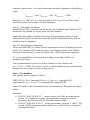
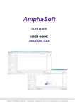
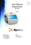
Step 1.3. Maximal output power limitations.
Maximal output power of the module (WMAX) is defined as a product of IMAX and
VMAX and can never exceed 1500W. As a result IMAX and VMAX parameters cannot
be selected independently. Graphically their mutual dependence is depicted on the
drawing below. The allowed area lies below the red curve.
Step 1.4. Input voltage limitations
Modules with the maximal output power up to 1000W can have dual 110/230VAC
input. Modules in 1000-1500W range can have 230VAC input only.
140
120
Vmax, V
100
80
60
40
20
20
40
60
Imax ,A
80
100
Step 2. TEC controllers.
Step 2.1. Quantity of temperature controllers
You may select module with none, one or two embedded temperature controllers.
In the case of two TEC controllers installed their parameters are selected and
controlled in independent way. Standardly the first TEC controller is used to
control the pumping diode temperature; the second one is used to control the laser
rod temperature.
Step 2.2. Parameters
Each temperature controller has limitations to its maximal output current and
maximal output voltage. Besides each temperature controller has limitation to its
maximal output power. As a result temperature controller parameters should be in
range:
IMAX(TEC) < 10A, VMAX(TEC) < 20V, WMAX(TEC) < 150W
Exact IMAX(TEC) and VMAX(TEC) ratio depends on V/A curve of your Peltier and
should be chosen in accordance with its datasheet.
Step 2.3. Thermistor limitations
Standardly our TEC controllers are designed to get feedback from 10kOhm NTC
thermistors. By default we supply them with our modules.
Sometimes laser diode assembly has already incorporated thermistor of some
different kind. In that case please submit the detailed information about how the
feedback loop is organized.
Step 2.4. Heating power limitations
Please note that LDD-2U cannot provide temperature control for high power laser
diodes. For example 500W (optical power) laser diode produces about 500W of
heat power that cannot be removed with the only 150W temperature controller.
It’s your responsibility to design proper cooling system and to define its
parameters precisely.
Our recommendation is not to use Peltier cooling for laser diodes with
IMAX * VMAX > 150W. Of course it’s just a recommendation and the certain border
depends on exact design of your cooling system.
Step 3. Part numbers
Part number has the format as follows:
LDD-2U-IMAX/VMAX-(optionally)IMAX(TEC1)/VMAX(TEC1)-(optionally)R1(optionally)IMAX(TEC2)/VMAX(TEC2)-(optionally)R2-(optionally)DI
where R1 and R2 is the information about your thermistors, DI means dual input
option
Examples.
• LDD-2U-100A/2V-8A/15V – current source with 100A maximal output
current, 2V compliance voltage; one temperature controller with 8A
maximal output current and 15V maximal output voltage
• LDD-2U-100A/20V-8A/15V – wrong part number, because 1) 100A * 20V
exceed 1500W maximal possible output power and 2) Peltier cooling isn’t
recommended there
• LDD-2U-40A/4V-5A/10V-25kOhmNTC-2A/2V-DI – current source with
40A maximal output current, 4V compliance voltage; two temperature
controllers; one with 5A maximal output current and 10V maximal output
voltage with the feedback from 25kOhm NTC thermistor; the other has 2A,
2V parameters, feedback loop is a standard one; dual input option
Description
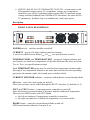
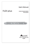
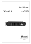
FRONT PANEL DESCRIPTION
POWER
SYNCHRO
CURRENT MONITOR
CURRENT
TEMPERATURE 1
SS
TEC1 TEC2 DIODE TEMPERATURE 2
POWER switch – switches module on and off
CURRENT – group of 4-digits indicator and two buttons;
is used to set diode current (from IMIN to IMAX; see specifications section)
TEMPERATURE1 and TEMPERATURE2 – groups of 4-digits indicator and
two buttons; are used to set temperature of the laser diode and the laser rod (from
TMIN to TMAX; see specifications section)
Each TEMPERATURE group may be switched into temperature monitor mode.
Pressing of two temperature buttons at the same time switches the corresponding
group into the monitor mode, the second press switches it back
CURRENT MONITOR indicator – measures and indicates current through diode
SS button – turns slow start regime on and off;
Slow start rise time can be settled through the RS-232 interface, by default it’s 5s
TEC1 and TEC2 buttons – turns temperature controllers on and off;
Once this button is pressed module is trying to stabilize diode(rod) temperature.
There are two LEDs nearby each TEC button.
• the left one indicates if temperature controller is turned on
• the right one indicates if diode(rod) temperature is set successfully
DIODE button – turns the current through diode on and off;
LED located nearby indicates if current is on
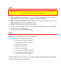
BACK PANEL DESCRIPTION
MAINS socket (cable is supplied with the driver) – to connect module to the mains
FUSES – two fuses; their rating depends on the laser diode driver selected
GROUND – ground stud
DIODE studs (cables are supplied with the driver) – two M6 studs to connect the
laser diode to the module
TEC1 and TEC2 connectors (cables are supplied with the driver) – two Molex
Minifit connectors to connect Peltier and feedback loop to the module
INTERLOCK connector – interlock circuit connection; the choke plug to shortcircuit the interlock is supplied with the module
FOOTSWITCH connector – footswitch/handswitch circuit connection; simple
handswitch is supplied with the driver; the choke plug to short-circuit the
footswitch is also supplied with the module
RS-232 connector (cable is supplied with the driver) – to connect module to the
computer
Warning! If the footswitch is already pressed when you are pressing DIODE
button, the module will start operations without any further warning. Be careful!
Safety
Warning! This equipment produces high voltages that can be very dangerous.
Don’t be careless around this equipment
• During operations all protective covers of the equipment must be securely in
place and all electrical connections must be properly attached
• Don’t remove protective covers! There are no user serviceable parts inside
this equipment. Do not self-repair the driver
• Module is designed to be properly grounded
• Do not turn the module on if it was already damaged with water, chemicals,
mechanical or electrical shock
• Do not operate without loads attached
Faults
Module sets the fault state in the following cases:
• module’s internal overheating
• overheating in TEC1 channel
• overheating in TEC2 channel
• NTC1 not connected
• NTC2 not connected
• diode not connected
• overcurrent in DIODE channel
• overvoltage in DIODE channel
• interlock circuit interrupted
Once the fault case has occurred you should eliminate the fault cause, then turn the
module off and then turn it on again.
Operations
•
•
•
•
•
•
•
•
•
•
•
•
•
•
•
•
•
•
connect laser diode to the module
(opt.) connect Peltiers to the module
(opt.) connect feedback loops to the module
(opt.) connect the module to the computer
connect footswitch (handswitch, choke plug) to the module
connect module to the mains
switch the module on (POWER switch)
set desired diode current (CURRENT buttons)
(opt.) set desired diode temperature and laser rod temperature
(TEMPERATURE1 and TEMPERATURE2 buttons)
turn on or turn off slow start (SS button), set its parameters (via RS-232)
(opt.) select pulsed operation mode instead of CW (CW by default), set
parameters of the pulsed mode (via RS-232)
(opt.) turn temperature controllers on (TEC1 and TEC2 buttons); it’s
recommended to wait while desired diode temperature will become
established
enable the current through diode (DIODE button)
press footswitch
…
turn the current through diode off (DIODE button)
turn temperature controller off (TEC1 and TEC2 buttons)
switch the module off (POWER switch)
Specifications
INPUT
110VAC or 110/230VAC, 50/60 Hz
Voltage
(depends on the output power and if DI
option is selected)
LASER DIODE DRIVER SPECIFICATIONS
Max. output current (IMAX)
selectable in range 10A-100A range
Max. output voltage (VMAX)
selectable in range 2V-150V range
Max. output power
IMAX * VMAX; cannot exceed 1500W
Output current adjustment range 10%-100% of IMAX
Efficiency
more than 80%
< 1 ms (10% to 90% full current)
Rise/fall time
< 500 us on request
Current regulation accuracy
< 1% of IMAX
Current value error
< 1% of IMAX
Current overshoot
< 1% of IMAX
TEC CONTROLLERS SPECIFICATIONS
Type
bidirectional
Max. output current
up to 10A
Max. output voltage
up to 20V
Max. output power
cannot exceed 150W
Feedback loop
10 kOhm NTC (other on request)
Temperature set points
10-40 ºC (other on request)
Temperature set points accuracy
0.1 ºC
and stability
PROTECTIONS
Module’s overheating
70 ºC
Overheating in TEC channels
TMAX + 10 ºC (other on request)
Diode overcurrent protection
+
SAFETY
PFC value
> 0.98 (active)
Leakage current
< 500 μA
Input/output isolation voltage
4000 VAC
Safety approval
IEC60950, IEC60601-1
EMC approval
EN55011 (Class A)
Forced air cooling with embedded fans
COOLING
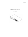
19’’ width; 2U height; 250mm depth
DIMENSIONS
ENVIRONMENT
Operation temperature
Storage temperature
Humidity
0 … +40 °C
-20 … +60 °C
90%, non-condensing
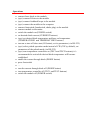
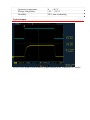
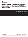
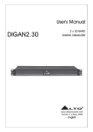
Typical output
Yellow curve depicts some arbitrary output current pulse. Timescale is 1 ms/div.
RS-232 interface description
RS-232 connection parameters: 38400 bps, 8 data bits, 1 stop bit, no parity.
Command format is: {command} {data (optionally)} {end-of-line}
• command is 1 character long (see list below)
• data is ASCII-string of adjusting value
• end-of-line symbols are \r\n or \n
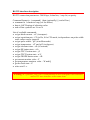
List of available commands:
• set/get diode current - с/C (in ampere)
• set/get repetition rate - f/F (in Hz, 0 for CW mode, in dependence on pulse width
some values can be ignored)
• set/get pulse width – p/P (in milliseconds)
• set/get temperature – t/T and g/G (in degrees)
• set/get slowstart time - s/S (is seconds)
• set/get SS button state - a/A
• set/get TEC1 button state - j/J
• set/get TEC2 button state - u/U
• set/get DIODE button state - r/R
• get current monitor value - Y
• get temperature monitors value – W and Q
• get the fault state - Z
• echo on/off - e
Warning! It’s possible, but it isn’t recommended to use front panel user interface
and rs-232 user interface at the same time