1
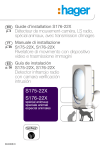
Updated for e-Nova applications
GB
Contents
1. Introduction
1. Introduction .................... 72
IMPORTANT
• Some functions are only available with control panel version 2.0.0 or later (enter
on the control panel keypad to check the version).
• Operating differences with respect to former ranges are described in the compatibility booklet available
in the Daitem Installers section at www.daitem.co.uk.
4. Parameter-setting.......... 76
5. Installation
precautions..................... 77
6. Installing the detector ... 77
6.1 Fixing the detector
in place....................... 78
6.2 Setting the
detection range.......... 80
6.3 Setting the vertical
angle........................... 81
7. Operating options .......... 82
8. Testing operation ........... 83
8.1 Testing the
detection zone ........... 83
8.2 Performing
a real test.................... 83
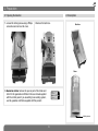
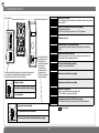
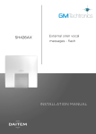
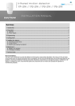
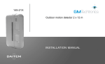
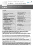
The 12 m external motion detector with
anti-mask feature detects intruders
before they break in. Fitted with a
specific lens and two infrared sensors,
the detector can tell the difference
between a human being and a small
animal. Combined with internal
electronics, the anti-mask feature
detects attempts to mask the detector.
Its detection angle can be adjusted by
adding masking strips to the lens. The
detector’s sensitivity can be set to
reduce the likelihood of false alarms
triggered by movement (cars, persons or
animals outside of the required detection
zone). The ideal installation height is
between 2.5 and 3 m as this makes it
difficult for intruders to access the
detector.
9. Maintenance................... 84
9.1 Fault indications......... 84
9.2 Changing
the battery .................. 84
)
Side view
9m
5,5 m
3m
3. Recognition
programming.................. 75
3m
2. Preparation ..................... 73
2.1 Opening
the detector................ 73
2.2 Description................. 73
2.3 Power supply ............. 74
Adhesive masking strips (supplied)
Top view
8m
0
8m
12 m
10. Technical data .............. 85
The detector comprises a mechanical device for adjusting the
detection zone. The protected area can be checked with the
help of a LED located behind the lens.
72
GB
2. Preparation
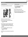
2.1 Opening the detector
2.2 Description
1. Loosen the locking screw using a Philips
screwdriver and remove the cover.
Back box
d
.
2. Remove the back box.
d
Cover
3. Guarantee sticker: remove the pre-cut part of the sticker and
stick it to the guarantee certificate in the user manual supplied
with the control panel. If you are adding to an existing system,
use the guarantee certificate supplied with this product.
SH146AX
Coller sur certif
A1142A047879
SH146AX
Coller sur certif
A1142A047879
Locking screw
73
GB
Detection module
(front view)
Cover
2.3 Power supply
Connecting the battery.
Detection circuit
connector
Set of upper
detection
beams
Operating option
dip switches
Set of lower
detection beams
Sensitivity
selection dip
switch
Anti-mask
selection dip
switch
Angle adjustment
bracket
d
LED
Detection module
(rear view)
Sheet of adhesive masking strips
Test button
Programming
LED
When the detector is switched on, the
LED flashes every second for 45 s
(detection circuit stabilisation period).
The programming LED lights up for 2 s.
Lithium battery
connector
Lithium battery
Radio card
IMPORTANT: if the LED does not flash,
check the connector is in the right
position (detection circuit).
Bag of accessories
Two 3 x 10 mm screws
(for fixing cover)
Two 4 x 20 mm screws (for
fixing box to adjustment bracket)
74
GB
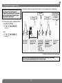
3. Recognition programming
IMPORTANT: the device does not need to be
placed close to the control panel for
recognition programming. In fact, we advise
you to move the product at least 2 metres
away from the control panel.
2. Proceed as follows to programme the detector to be recognised by the control panel.
“group?”
“detector X”
“time delay?”
“beep, detector X,
group Y, immediate
(or delayed
or combined)”
1. Put the control panel in installation mode
by entering the following:
)))
))
master code
then:
then
to
installer code
*
to
10 s max.
Press * then #
on the control
panel keypad
Press and hold the
“test” button until
the control panel
responds
The control panel
waits for a group
to be chosen (from
1 to 8)*. Choose
the groups by
pressing the
corresponding
numeral on the
control panel keypad
Select the time delay:
0: immediate
1: delayed
2: combined
Use the control panel
keypad to do this.
The control panel
gives a voice
message to
confirm
* Depends on the type of the control panel
IMPORTANT: the control panel indicates there is an error by emitting 3 short beeps.
When this happens programming should be carried out again.
75
GB
4. Parameter-setting
Parameter-setting
sequence
Parameter n°
5
Alarm level
Intrusion
Prealarm
Deterrence
Warning
Parameter value
1
2
3 (factory setting)
4 (the feature is available using control panels
with 2.0.0 version software or later)
{
{
t
The motion detector is factoryconfigured for a deterrence (see
your control panel installation
guide for system responses). The
alarm level can be changed by
resetting the parameters as
shown opposite.
Programming
LED on
Programming
LED off
about
5 s.
about 10 s.
about 10 s.
about 2 s.
Programming
sequence
Test
button
Press the
button 5 times
for the
parameter
number
To start,
press and
hold until the
LED goes out
Parameter-setting example:
setting the detector to full ) prealarm :
parameter number 5, parameter value 2.
Press the button
1 to 4 times
for the parameter
value
2
Start
Press the
button 5 times
to select the
alarm level
76
Press
once
to create
a space
Press the button
twice to select the
prealarm
To end,
press and
hold the
button until
the LED goes
out
about 2 s.
t
5
Press and
hold until the
LED briefly
goes out
End
Programming LED
permanently on =
parameter set
correctly
GB
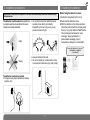
5. Installation precautions
6. Installing the detector
IMPORTANT: make sure each product is at least two metres away from other devices, except
other detectors.
The detector must be placed: perpendicular
to entrance points to be protected to ensure
intruders are quickly detected.
• do not place where the detection beams
are likely to be directly or indirectly
impacted by the sun’s rays or by a very
powerful source of light,
Right
Before fixing the detector in place:
1. Define the fixing height (2.5 to 3 m).
2. Determine the detection zone.
3. With the detector in the chosen location,
check the radio link with the control panel:
Press (> 5 s) on the detector “test” button.
The control panel will issue the voice
message: “beep, test detector X
(personalised message), group Y,
immediate (or delayed or combinated)”.
“beep, test detector X, group Y,
(immediate or delayed
or combined)”
Wrong
• skew in relation to the wall,
• do not fix directly on a metal wall or close
to sources of interference (e.g. heat pump).
The detector must not be placed:
• facing a moving object (branches, bushes,
curtains, etc.),
77
)))
))
GB
6.1 Fixing the detector in place
Fixing it flat against the wall
The detector can be fixed to the wall without
the bracket if it does not need any horizontal
or vertical adjustments.
Fixing the angle adjustment bracket
The bracket makes it possible to adjust the horizontal angle by approximately 90 degrees.
If the ground is uneven and therefore not parallel to the base of the unit, the bracket allows
for a vertical adjustment of approximately 20 degrees.
IMPORTANT
• Do not modify the
detection distance
with the bracket.
• Use the masking
strips to adjust the
detection distance.
Blanks
Screws
(not
supplied)
1. Pre-drill the 2 blanks on the back box.
2. Fix the back box to the wall using suitable
washers and screws (not supplied).
3. Install the main unit and set the detection
range as described in the next chapter.
1. Remove the locking screw.
2. Remove the pivot protection cover by pressing
on the detector cover support with your thumb.
Use a flat-headed screwdriver to remove
it if it is stuck.
Pivot protection cover
Support on detector cover
Locking
screw
78
GB
3. Loosen the adjustment
screws so as to be able to
rotate the axle.
4. Decide which way round to fix the bracket depending on
the required detector angle. Then fix the angle adjustment
bracket to the wall using suitable screws and washers
(not provided).
5. Prepare the 3 blanks on the back
box.
Blanks
Screws
(not supplied)
Adjustment screws
6. Tighten the central locking screw and the other two screws and then adjust the horizontal angle.
Adjustment
screw
7. Install the main unit and the
cover on the base. Re-insert
the locking screw (without
tightening it) and the
protection cover.
8. Adjust the vertical angle as
described in the next
chapter.
4 x 20 mm screw
Central locking screw
4 x 20 mm screw
79
GB
6.2 Setting the detection range
1. Install the detector at a height of 2.5
to 3 m. The lower edge of the detector
must be parallel to the ground.
2. Apply the masking strips to the lens to adjust the detection distance. To set a distance
below the standard 12 m, choose one of the three shapes and apply it to the lens.
Internal views of the lens
9m
4m
5.5 m
3m
3m
Parallel
2.5 to 3 m
3
STEP 1 (9.0 m)
Applying a masking strip to a specific area
2.5 to 3 m
12 m
80
2
STEP 2 (5.5 m)
3m
1
STEP 3 (4.0 m)
GB
6.3 Setting the vertical angle
1. IMPORTANT: to ensure proper detector performance, set the vertical angle so that the base of the product is parallel to the ground.
2. Determine the required detection distance and mask the lens using the appropriate strips.
3. Perform a detection test making sure that the 2 beams (1 and 2) are interrupted one after the other.
IMPORTANT: the detection zone can be adjusted using the
masking strips without changing the angle. The base of the
detector should be parallel to the ground to ensure the quoted
detection range is achieved. Minor rangte adjustments can be
effected by adjusting the vertical angle as follows.
12 m
Beam 1
Beam 2
If the detection distance
is shorter than required,
increase the vertical
angle.
3m
If the detection distance
is in line with the
requirement, there is no
need to change the angle.
If the detection
distance is greater
than required, reduce
the vertical angle.
0°
0 degrees is the right setting for an installation
height of 3 m as long as the wall is perpendicular
to the ground over the entire detection length
Adjustment: 1 click corresponds
to a 2.5 degree upward adjustment
4. Tighten the locking screw.
81
5° (2 clicks)
10° (4 clicks)
GB
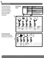
7. Operating options
Dip switches
1 2 3 4 5 6
Detector in test mode
The LED lights up when something is detected whatever the position
of dip switch 6.
1 2 3 4 5 6
Detector in normal user mode (factory setting)
Normal operating mode
The LED is not lit when dip switch 6 is in OFF position.
ON
ON
ON
Detection every 5 s
1 2 3 4 5 6
1 2 3 4 5 6
Detection every 120 s (factory setting)
Recommended dip switch position to economise on the lithium
battery.
1 2 3 4 5 6
Hostile environment sensitivity
(difficult environment: wind, moving tree leaves or branches, etc.)
The sensitivity will necessarily be lower.
1 2 3 4 5 6
Normal sensitivity (factory setting)
Sensitivity for most installations.
ON
ON
Infrared sensitivity (depends on the ambient temperature):
an H setting may be advisable in regions where the
climate is mild or hot for most of the year.
Anti-mask (24-hour
protection): when
the detector is
completely masked
for roughly 3
minutes (i.e. an
opaque object is
placed over the
lens), this triggers a
tamper warning.
H: high sensitivity
ON
ON
Mandatory position (factory setting)
1 2 3 4 5 6
ON
H
Mandatory position (factory setting)
1 2 3 4 5 6
M
M: medium sensitivity (factory setting)
L
L: low sensitivity
1 2 3 4 5 6
Detection LED lighting
(leads to a decrease in detector battery life)
The LED lights up with each detection.
1 2 3 4 5 6
Non-lighting of detection LED (factory setting)
The LED does not light up even when an intruder is detected.
ON
ON
H: high anti-mask sensitivity
factory setting
HI
STD
STD: standard anti-mask sensitivity
OFF
OFF: anti-mask function deactivated (factory setting)
82
GB
8. Operating test
8.1 Testing the detection zone
8.2 Performing a real test
1. Mount the detection module and the lens on the back box.
1. Put the control panel in user mode by entering:
installer code
2. Put the control panel in Total Arm mode.
3. Wait 120 s for the detector to become activated.
4. Walk across the protected area and check the control panel
response (see control panel installation manual).
2. Close the detector and tighten the locking screw.
3. Put the control panel in test mode by entering the following:
master code
4. Check the detection zone using the LED and adjust if necessary.
Each time something is detected, the control panel issues the
voice message: “Beep, deterrence detector X” (depending on the
configuration).
5. Put the control panel back in installation mode by entering:
installer code
6. Open the detector, set the infrared sensitivity if necessary and then
close it.
83
GB
9. Maintenance
Recommendations
The user must not attempt to access the
siren’s internal parts, except areas described
in this manual. If the user does access these
parts, the product guarantee will be
considered null and void and DAITEM shall
not be held responsible for any problems.
Touching the siren’s internal parts and/or
electronic components can damage the
product. Furthermore, the siren is designed
in such a way that these parts and
components do not need to be accessed for
operation or maintenance purposes.
9.1 Fault indications
The control panel responds to detector
battery faults, tamper faults and radio faults.
Battery fault:
Following a system command, the control
panel issues the voice message:
“Beep, fault, battery, detector X”.
Tamper fault:
Following a system command, the control
panel issues the voice message:
“Beep, fault, tamper, detector X”.
This fault is caused by the detector box not
being closed properly but may also be
triggered when the detector is completely
masked (the anti-mask function is triggered
when an opaque obstacle is placed in front
of the lens).
Radio fault
Following a system command, the control
panel issues the voice message:
“Beep, fault, radio, detector X”.
IMPORTANT: briefly press on the test button
to check the detector’s battery. The radio
card LED lights up red.
9.2 Changing the battery
IMPORTANT: the detector’s parameters are
saved when the battery is changed.
1. Put the Control panel into the Installation
mode by requesting the User to enter the
following:
master code
then enter:
installer code
2. Open the detector box
(see § 2. Preparation).
3. Replace the flat lithium battery and close
the detector.
4. Put the control panel back in user mode
by entering:
installer code
5. Perform the operating test again
(see § 8. Operating test).
• The lithium battery pack must be replaced by the same type of pack with the same technical
characteristics, i.e. (3.6 V - 4 Ah).
• We advise you to use the DAITEM BatLi05 pack available in the catalogue in order
to guarantee individual safety and equipment reliability.
Li
• Dispose of the waste lithium power pack in an appropriate recycling bin.
84
GB
10. Technical data
Technical specifications
12 m external motion detector
with anti-mask function
Type of detection
Coverage
Adjustable detection distances
Use
Battery
Battery life
dual passive infrared
12 m – 85°
4 m, 5.5 m, 9 m and 12 m
interior/exterior
BatLi05 3.6 V – 4 Ah lithium battery
• 5 years when anti-mask function is not
validated
• 3 years when anti-mask function is
validated
Radio links
TwinBand® 400/800 MHz
Wall fixing
• flat
• on angle adjustment bracket (supplied)
Fixing height
2.5 to 3 m
Operating temperature
- 20°C to + 60°C
Mechanical protection rating
IP 55
Anti-tamper protection
against opening
Anti-mask function
24-hour protection
Dimensions (without angle bracket) 148 x 92 x 197.5 mm
Weight
630 g (with battery, bracket and cover)
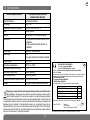
Disposing of waste electrical and electronic devices at the end of their service
life (Applicable in European Union countries and other European countries with a
waste collection system). This symbol on products or product packaging indicates
that the product must not be thrown out with normal household waste. It must be taken to
an appropriate collection point for recycling waste electrical and electronic equipment. By
disposing of such products in the appropriate manner, you are helping to prevent any
harmful effects they may have on the environment and human health. For further information about recycling this product, you should consult your local authorities, waste collection
centre or the shop where you bought the product.
85
DECLARATION OF CONFORMITY
GB
Manufacturer: Hager Security SAS
13
Address: F-38926 Crolles Cedex - France
Product type: Exterior 12 m motion detector with anti-mask function
Trade mark: Daitem
We declare under our sole responsibility that the product to which this declaration
relates is compliant with the essential requirements of the following directives:
• R&TTE Directive: 99/5/CE
• Low Voltage Directive: 2006/95/CE
• ROHS Directive: 2002/95/CE
in compliance with the following harmonised European standards:
Product reference
EN 300 220-2 V2.1.2
EN 50130-4 (95) + A1 (98) + A2 (2002)
EN 60950 (2006)
EN 301 489-1 V1.8.1
SH146AX
X
X
X
X
This product can be used in all EU and EEA countries and Switzerland.
Crolles, 02.04.2013
Signature:
Patrick Bernard
Research & Development Director
Non-binding document, subject to modifications without prior notice.
86
87
805037/B - 04.2013