1
145-21X
Outdoor motion detector 2 x 12 m
INSTALLATION MANUAL
Summary
1. Introduction .................................... ........... 67
2. Preparation ..................................... ........... 69
2.1 Opening the detector........................... . 69
2.2 Power supply ................................... ..... 69
3. Programming..................................... ........ 70
4. Configuration.................................... ......... 71
5. Installation precautions........................ .... 72
6. Installation.................................... .............. 73
6.1 Testing the radio link ......................... .... 73
6.2 Fixing ......................................... ............ 73
7. Configuration and adjustments
of detection....................................... ......... 74
7.1 Range of detection ............................. .. 74
7.2 Horizontal adjustment
of the detection angle ........................... 76
7.3 Adjustment of the sensitivity ................ 77
7.4 Adjustment of the operational
options ............................................ ...... 77
8. Operating test.................................. .......... 78
8.1 Detection zone test............................ ... 78
8.2 Real test ...................................... .......... 78
9. Maintenance ..................................... ......... 78
9.1 Fault indication............................... ....... 78
9.2 Changing the battery ........................... . 78
GB
Recommendations
The user must not attempt to access the siren’s int ernal parts, except areas described in this
manual. If the user does access these parts, the pr oduct guarantee will be considered null
and void and DAITEM shall not be held responsible f or any problems. Touching the siren’s
internal parts and/or electronic components can dam age the product. Furthermore, the siren
is designed in such a way that these parts and comp onents do not need to be accessed for
operation or maintenance purposes.
1. Introduction
IMPORTANT
• Some functions are only available with control pa
nel version 2.0.0 or later
(enter
) on the control panel keypad to check the v
ersion).
• Operating differences with respect to former rang
es are described in the compatibility booklet
available in the Daitem Installers section at www.d
aitem.co.uk .
The 2 x 12 m external motion detector has been spec ially designed to detect intruders before
they have a chance to break in by monitoring the ar ea outside the protected site.
Because both detection systems operate on either si de of the detector and detection can be
adjusted to provide narrow 4 to 24 m protection (2 x 12 m on each side), this is the ideal
product for protecting a façade.
Its immunity to false alarms caused by sunlight or car headlights is backed up by its highly
reliable pet-tolerant detection system (both detect ion beams have to be broken in order to
trigger a prealarm or alarm). Its performance is fu rther enhanced by a temperature
compensation system that automatically adjusts and increases detection sensitivity when the
outside temperature comes close to that of a human being (35°C - 37°C).
10. Technical data ................................. ........ 79
67
GB
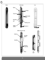
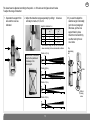
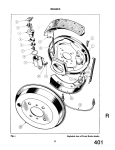
Back box
Detector module
Cover
Radio box
Led Indicator
Top pyro sensor
Switch for sensitivity
options
Range detection
switch
Bottom pyro sensor
Anti-tamper
mechanism
Locking screw
Locking screw x 2
Detection unit with radio box open
Radio board
Lithium battery
connector
Lithium battery
Indicator lamp
for programming
Test key
68
Lens
support
Cover
GB
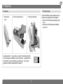
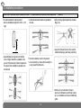
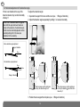
2. Preparation
2.1 Opening
2.2 Power supply
1. Remove the
cover.
2. Remove the back box.
3. Open the radio box.
d
d
d
Guarantee sticker: remove the pre-cut part of the sticker and stick
it to the guarantee certificate in the user manual s upplied with the
control panel. If you are adding to an existing sys tem, use the
guarantee certificate supplied with this product.
145-21X
Coller sur certif
A1142A047879
145-21X
A1142A047879
69
Coller sur certif
Connect the battery. When switched on, the
detector runs a self-test. If the self-test is:
• correct, the LED indicator lamp lights up for
2 sec.,
• incorrect, the LED indicator lamp flashes
every 5 sec.
GB
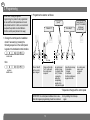
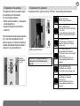
3. Programming
IMPORTANT: during recognition
programming, the product to be programmed
for use with the control panel does not need
to be placed next to it. In fact, we recommend
you place the product at a short distance
from the control panel (at least 2 m away).
2. Programme the detector as follows:
“group?”
“detector X”
1. Change the control panel to installation
mode if necessary by pressing the
following sequence on the control panel
keypad or the hardwired control interface
master code
)))
))
then
to
*
to
10 s max.
then:
engineer
installer code
“time delay?”
“beep, detector X,
group Y, immediate
(or delayed
or combined)”
Press * then #
on the control
panel keypad
Press and hold the
“test” button until
the control panel
responds
The control panel
waits for a group
to be chosen (from
1 to 8)*. Choose
the groups by
pressing the
corresponding
numeral on the
control panel keypad
Select the time delay:
0: immediate
1: delayed
2: combined
Use the control panel
keypad to do this.
The control panel
gives a voice
message to
confirm
* Depends on the type of the control panel
IMPORTANT: the control panel indicates there is an e
When this happens programming should be carried out
70
rror by emitting 3 short beeps.
again.
GB
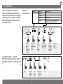
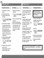
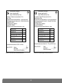
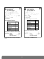
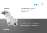
4. Configuration
Sequence of
parameter setting
Parameter n°
5
Alarm level
Intrusion
Prealarm
Deterrence
Warning
Indicator lamp
for
programming it
Indicator lamp
for programming about 10 sec.
not lit
Parameter value
1
2
3 (factory setting)
4 (the feature is available usingneclosntrol pa
with 2.0.0 version software or later)
{
{
?
In factory configuration, the movement
detector is configured in deterrence (for the
reactions of the system see the control panel
installation guide). It is possible to modify the
level of alarm using the following sequence
of parameter setting:
about
5 sec.
about 10 sec.
about
2 sec.
sequence
To start the
sequence
press and
hold the
button until the
LED indicator
lamp goes out
Configuration example: setting the
detector for an alarm level when a prealarm
is triggered: Parameter n° 5, Parameter value
2.
Press 5 times
depending
on the required
parameter
number
Press 1 to 4
times depending
on the required
parameter value
2
Start
Press 5 times
to select
the alarm
level
71
Press
once to
accept
selection
Press 2 times
to select
the preal
level
To end the
sequence press
and hold the
button until the
LED indicator
lamp goes out
about
2 sec.
?
5
Press and
hold until the
LED
indicator
lamp briefly
goes out
End
LED indicator
lamp lit =
correct
configuration
GB
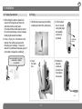
5. Installation precautions
IMPORTANT: Make sure there is a distance of at least
The motion detector must be placed:
• with an installation height from 0.8 to 1.2 m
high,
2 meters between each product, except between two
• so that the detection beams are parallel to
the wall.
detectors.
• facing moving objects (branches, bushes,
flags, etc),
H
• away from the wall (must not be used for
infrared barrier type perimeter protection),
• perpendicular to the ground, so that the
zone of higher detection is parallel to the
ground. If the detector is tilted compared to
the ground, the reliability of operation can
be reduced,
The motion detector must not be placed:
• in an area likely to receive direct sunlight or
a very powerful light source,
• directly on to a metal wall or close to
sources of interference (electricity meters,
etc.) or ventilation such as air-conditioning
grilles.
72
GB
6. Installation
6.1 Testing the radio link
1. Before fixing the detector, place them
close to the fixing point and check the
radio link with the control panel.
If the link with the control panel is correct,
the control panel issues a voice message
identifying the detector activated.
2. Press (> 5 sec.) the “test” button on the
detector, the control panel issues the
following voice message: “beep, test,
detector X (customised message), group Y,
(immediate or delayed or combined)”.
“beep, test detector X, group Y,
(immediate or delayed
or combined)”
6.2 Fixing
1. Drill the fixing holes using the drilling
template provided in the packing box.
Top
2. To fix the back
box on the wall
using wall plugs
and suitable
screws (not
provided).
Fastening
screw
Bottom
3. Close
the radio
box.
d
)))
))
4. Position the
detection
module on
the back box
then tighten
the screws.
.
73
GB
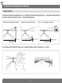
7. Configuration and adjustments of detection
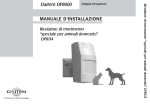
7.1 Range of detection
The higher beam remains always parallel on the grou nd. Being given that the beams (higher and lower) m ust be broken simultaneously to set
off an alarm, the range of the detector is limited to the range of the lower beam.
Detection: the lower and higher beams are broken
Range of detection
No detection: only the lower beam is broken
Range of detection
No detec
tion: only the higher beam is broken
Range of detection
The right-hand and left-hand detection beams must b e adjusted separately according to the detection en vironment.
74
GB
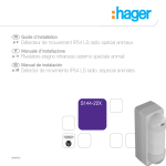
The lower beam is adjusted according to the positio n of the lens as the figures show it below.
To adjust the range of detection:
1. Separate the support from
lens and the cover as
indicated.
2. Adjust the detection ranges separately by sliding t he lenses
vertically to marks A, B, C or D.
3. If you wish to adjust the
detection angle horizontally,
go to the next paragraph.
Otherwise, put the lens
support back in place.
Check that it is held firmly
on either side by the six
cover slots.
Height of installation 1 m
Position
Standard range
(m)
12
8
5
2
A
B
C
D
Maximum range*
(m)
10 - 15
6 - 10
4-6
1.5 - 3
* The maximum range can vary from the standard
values according to the environmental conditions.
Position A (12 m)
IMPORTANT: the lenses
must not be positioned
crossways in the
lens support.
Top
depolarising
slot
(m)
1
5
10
12(m)
Position B (8 m)
Slots
(m)
1
5
10
12(m)
5
10
12(m)
5
10
12(m)
Position C (5 m)
(m)
1
Position D (2 m)
(m)
1
75
Bottom
closing
screw
GB
7.2 Horizontal adjustment of the detection angle
If there is an obstacle in the way of the
detection beams, they can be horizontally
offset by 3°.
To adjust the detection angle:
1. Separate the support from lens and the cover (see 1.Range of detection).
2. Adjust the detection angles separately by sliding t he lenses horizontally.
IMPORTANT: because an alarm is triggered
when both the upper and lower beams are
broken at the same time, the detection angle
of both must be horizontally adjusted. Set the
sensitivity setting to H in this case (see
Adjustment of the sensitivity).
Before detection angle adjustment
Range of detection
12 m
After detection angle adjustment
12 m
3°
0,6 m
Range of detection
When the lenses are at the right-hand
end stop, the detection angle is 0°.
When the lenses are not at the right-hand
end stop, the detection angle is offset from
the wall by 3°.
3. Position the lens support back in place (see 3.Range of detection).
76
GB
7.3 Adjustment of the sensitivity
This adjustment makes it possible to adjust
the sensitivity level of the detector.
For environmental conditions:
• difficult (wind, bad weather...), decrease the
sensitivity(position L),
• standard sensitivity leave the switch in
position M.
When the detection angle has been adjusted
by 3° (see Horizontal adjustment of the
detection angle), or if maximum sensitivity is
required at the detection limit (at a distance
of around 12 m), set sensitivity to H.
7.4 Adjustment of the operational
The adjustment of the options is done by 3 DIP swit ches located inside the detector.
ON
ON
ON
Operating options DIP switches
ON
Sensitivity
selector switch
(L, M, H)
IMPORTANT: if you position dip-switch 2
or dip-switch 3 on ON, this will lower the
battery life.
ON
ON
77
Detector in TEST mode ,
LED lights during each detection.
Detector in NORMAL mode,
LED remains off (except if the DIP switch
n° 3 is on ON).
The period between radio transmissions
depends on the position of DIP switch n° 2.
5 sec. battery saving timer
radio transmissions are limited to a 5
second timer interval even if multiple
detections occur.
120 sec. battery saving timer
Radio transmissions are limited to a
120 second timer interval even if multiple
detections occur.
Position recommended in the event
of frequent passage inside the zone
of detection.
Selecting LED indicator status
The LEDs light up on detection
in both test and normal operating mode.
Selecting LED indicator status
The LEDs light up on detection
in test mode only.
Position recommended in the event
of frequent passage inside the zone
of detection.
GB
9. Maintenance
8. Operating test
8.1 Detection zone test
1. Put DIP switch 1 in the ON
position.
2. Close the detector cover.
3. Switch the control panel to
test mode:
engineer
installer code
4. Check the area of detection
using the indicator LED and
adjust the detector if need be.
With each detection the
control panel issues the voice
message “Beep, deterrence
detector X” (depending on the
configuration).
5. Switch the control panel back
to installation mode, press:
8.2 Real test
9.1 Fault indication
1. Switch the control panel to
user mode:
The control panel takes battery
faults, anti-tamper faults and
radio faults on the detector into
account.
Battery fault
Following a system command,
the control panel issues the
following voice message: “beep,
fault, battery, detector X” .
Anti-tamper fault
Following a system command,
the control panel issues the
following voice message: “beep,
fault, anti-tamper, detector X” .
Radio fault
Following a system command,
the control panel issues the
following voice message: “beep,
fault, radio, detector X” .
engineer
installer code
2. Put your control panel in Total
Arm mode.
3. Wait for the exit time delay.
4. Cross over the protected area
and check that the control
panel responds (see your
control panel’s installation
manual).
engineer
installer code
6. Reopen the cover, to put DIP
switch 1 to OFF.
Close the detector cover and
tighten the locking screw.
9.2 Changing the battery
IMPORTANT: the detector’s
configuration is saved when the
battery is changed.
1. Switch the control panel to
installation mode and ask the
master user to press:
master code
then press:
engineer
installer code
2. Open the case of the detector
(see § Opening the detector).
3. Replace the used lithium
batery.
IMPORTANT: the test button makes it possible to chec
k if the battery
is OK. The indicator on the radio board lights red
when the button
is pressed.
78
GB
4. Switch the control panel back to user
mode, press:
engineer
installer code
5. Perform another operating test (see §
Operating test).
• The lithium battery pack must be replaced by
the same type of pack with the same technical
characteristics, i.e. (3.6 V - 4 Ah).
• We advise you to use the DAITEM BatLi05
pack available in the catalogue in order
to guarantee individual safety and
equipment reliability.
• Dispose of the waste lithium power
Li
pack in an appropriate recycling bin.
10. Technical data
Specifications
Outdoor motion detector 2 x 12 m
Detection
infrared
Coverage
2 x 2 to 12 m adjustable beam assemblies
Use
inside/outside
Power supply
3.6 V - 4 Ah BatLi05 lithium battery
Battery life
5 years in normal conditions of use
(110 detections max./day)
Radio links
TwinBand ® 400/800 MHz
Fixing methods
wall
Operating temperature
- 20°C a + 50°C
Degrees of mechanical protection
IP 55
Anti-tamper protection
against opening
Dimensions L x W x H
56 x 128 x 235 mm
Weight
596 g
Waste processing of electrical and electronic devic
es at the end of their service life (Applicable in European Union countries and other E uropean
countries with a waste collection system). Used on products or product packaging, this symbol indicate s that the product must not be thrown out with
household waste. It must be taken to a waste collec tion point for electrical and electronic product re cycling. When you make sure that this product is di sposed of in the most appropriate manner, you are he lping to protect the environment and human health. If you would like additional information concerning the
recycling of this product, please contact your town /city council, nearest waste collection centre or t he shop where you bought the product.
79
DÉCLARATION DE CONFORMITÉ
FR
Fabricant : Hager Security SAS
13
Adresse : F-38926 Crolles Cedex - France
Type de produit : Détecteur de mouvement extérieur 2 x 12 m
Marque : Daitem
Nous déclarons sous notre seule responsabilité que le produit auquel se réfère
cette déclaration est conforme aux exigences essent ielles des directives suivantes :
• Directive R&TTE : 99/5/CE
• Directive Basse Tension : 2006/95/CE
• Directive ROHS : 2002/95/CE
conformément aux normes européennes harmonisées sui vantes :
Références produits
Crolles, le 01.04.2013
Codice dei prodotti
EN 300 220-2 V2.1.2
EN 300 330-2 V1.3.1
EN 50130-4 (95) + A1 (98) + A2 (2002)
EN 55022 & 55024 (2002)
EN 60950 (2006)
EN 301 489-1 V1.8.1
145-21X
EN 300 220-2 V2.1.2
EN 300 330-2 V1.3.1
EN 50130-4 (95) + A1 (98) + A2 (2002)
EN 55022 & 55024 (2002)
EN 60950 (2006)
EN 301 489-1 V1.8.1
Ce produit peut être utilisé dans toute l’UE, l’EEA
DICHIARAZIONE DI CONFORMITÀ
IT
Fabbricante: Hager Security SAS
13
Indirizzo: F-38926 Crolles Cedex - France
Tipo di prodotto: Rivelatore PET immune esterno 2 lati x 12 m
Modello depositato: Daitem
Dichiariamo sotto la nostra responsabilità che i pr odotti cui questa dichiarazione
si riferisce sono conformi ai requisiti essenziali delle seguenti Direttive Europee:
• Direttiva R&TTE: 99/5/CE
• Direttiva Bassa Tensione: 2006/95/CE
• Direttiva ROHS: 2002/95/CE
in ottemperanza alle seguenti Normative Europee arm onizzate:
X
X
X
Questi prodotti possono essere utilizzati in tutta
et la Suisse
Crolles, le 01.04.2013
Signature :
Patrick Bernard
Directeur Recherche et Développement
Document non contractuel, soumis à modifications sans préavis.
145-21X
X
X
X
l'UE, i paesi di EEA, Svizzera.
Firmato:
Patrick Bernard
Direttore Ricerca e Sviluppo
Documento non contrattuale, soggetto a modifiche senza preavviso.
80
KONFORMITÄTSERKLÄRUNG
DE
Hersteller: Hager Security SAS
13
Adresse: F-38926 Crolles Cedex - France
Gerätetyp: IR-Bewegungsmelder (Außenbereich)
Marke: Daitem
Diese Produkte entsprechen den grundsätzlichen Anfo rderungen der folgenden
europäischen Richtlinien, und zwar:
• Richtlinie R&TTE: 99/5/EG
• Niederspannungsrichtlinie: 2006/95/CE
• Richtlinie ROHS: 2002/95/CE
konform mit folgenden europäischen harmonisieren No rmen:
Produktreferenz
EN 300 220-2 V2.1.2
EN 300 330-2 V1.3.1
EN 50130-4 (95) + A1 (98) + A2 (2002)
EN 55022 & 55024 (2002)
EN 60950 (2006)
EN 301 489-1 V1.8.1
DECLARACIÓN DE CONFORMIDAD
ES
Fabricante: Hager Security SAS
13
Dirección: F-38926 Crolles Cedex - France
Tipo de producto: Detector de exterior 2 x 12 m
Marca: Daitem
Declaramos bajo nuestra responsabilidad que los pro
ductos a los que se refiere esta
declaración están conformes con las exigencias esen
ciales de las directivas siguientes:
• Directiva R&TTE: 99/5/CE
• Directiva Baja Tensión: 2006/95/CE
• Directiva ROHS: 2002/95/CE
De acuerdo con las siguientes normas europeas harmo nizadas:
Ref. producto
EN 300 220-2 V2.1.2
EN 300 330-2 V1.3.1
EN 50130-4 (95) + A1 (98) + A2 (2002)
EN 55022 & 55024 (2002)
EN 60950 (2006)
EN 301 489-1 V1.8.1
145-21X
X
X
X
Dieses Produkt darf in der EU, dem EWR und der Schw eiz betrieben werden.
Este producto puede ser utilizado en toda la UE, la
Crolles, den 01.04.2013
Crolles el 01.04.2013
Unterschrift:
Patrick Bernard
Leiter Forschung & Entwicklung
Hinweis: Änderungen der technischen Daten und des Designs aufgrund
von Produktverbesserungen bleiben uns ohne Ankündigung vorbehalten.
Nachdruck, auch auszugsweise, nur mit ausdrücklicher Genehmigung des
Herstellers.
145-21X
X
X
X
EEA y Suiza
Firmado:
Patrick Bernard
Director Investigación y Desarrollo
Documento no contractual, supeditado a posibles mod ificaciones sin preaviso.
81
GELIJKVORMIGHEIDSVERKLARING
NL
Fabrikant: Hager Security SAS
13
Adres: F-38926 Crolles Cedex - France
Soort produkt: Externe bewegingsdetector 2 x 12 m • Merk: Daitem
Wij verklaren op onze eigen verantwoordelijkheid dat het product waarop deze
gelijkvormigheidsverklaring betrekking heeft, beantw oordt aan de fundamentele
voorschriften van de volgende richtlijnen:
• Richtlijn betreffende Radioapparatuur en telecommu
nicatie-eindapparatuur (R&TTE):
99/5/CE
• Richtlijn betreffende de Laagspanning: 2006/95/CE
• Richtlijn ROHS: 2002/95/CE
Volgens de volgende geharmoniseerde Europese normen :
Productreferentie
EN 300 220-2 V2.1.2
EN 300 330-2 V1.3.1
EN 50130-4 (95) + A1 (98) + A2 (2002)
EN 55022 & 55024 (2002)
EN 60950 (2006)
EN 301 489-1 V1.8.1
DECLARATION OF CONFORMITY
GB
Manufacturer: Hager Security SAS
13
Address: F-38926 Crolles Cedex - France
Product type: Outdoor motion detector 2 x 12 m
Trade mark: Daitem
We declare under our sole responsibility that the p roduct to which this declaration
relates is compliant with the essential requirement s of the following directives:
• R&TTE Directive: 99/5/EEC
• Low voltage directive: 2006/95/EC
• Directive ROHS: 2002/95/EC
in compliance with the following harmonised Europea n standards:
Products code
EN 300 220-2 V2.1.2
EN 300 330-2 V1.3.1
EN 50130-4 (95) + A1 (98) + A2 (2002)
EN 55022 & 55024 (2002)
EN 60950 (2006)
EN 301 489-1 V1.8.1
145-21X
X
X
X
145-21X
X
X
X
This product can be used in all EU, EEA Countries a nd Switzerland.
Dit product mag gebruikt worden in de Europese Unie , de EEZ en in Zwitserland.
Crolles, op 01.04.2013
Crolles, 01.04.2013
Handtekening:
Patrick Bernard
Directeur Research & Ontwikkeling
Niet-contractueel document onderworpen aan wijzigingen zonder voorafgaan de
kennisgeving.
Signature:
Patrick Bernard
Director of Research and Development
Non-contractual document, may be modified without prior notice.
82
83
804942/C - 09.2013