1
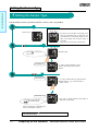
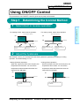
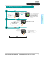
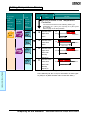
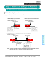
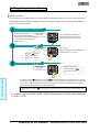
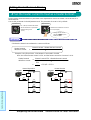
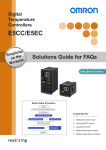
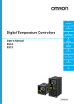
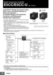
Digital Temperature Controllers E5CC/E5EC Solutions Guide for FAQs Using Basic Functions Basic Setup Procedure START Connect sensor and operating terminal. Turn ON power. 1. 2. CONTENTS Setting the sensor type Using ON/OFF control 3. Using PID control Setting the set point 4. Setting temperature alarms 5. 1. Setting the Sensor Type 2. Using ON/OFF Control Setting heater burnout alarms 3. Using PID Control 4. Setting Temperature Alarms Operation 5. Setting Heater Burnout Alarms Introduction This Solutions Guide is based on customer questions that were received at OMRON's Customer Support Center. It provides practical operating procedures for setting and changing the most common items: setting the sensor type, ON/OFF control, PID control, setting temperature alarms, and setting heater burnout alarms. Keep this Guide in a convenient location onsite to help you make settings and changes. If you are having trouble with Temperature Controller settings, this is the guidebook for you. OMRON, 2012 All rights reserved. No part of this publication may be reproduced, stored in a retrieval system, or transmitted, in any form, or by any means, mechanical, electronic, photocopying, recording, or otherwise, without the prior written permission of OMRON. No patent liability is assumed with respect to the use of the information contained herein. Moreover, because OMRON is constantly striving to improve its high-quality products, the information contained in this manual is subject to change without notice. Every precaution has been taken in the preparation of this manual. Nevertheless, OMRON assumes no responsibility for errors or omissions. Neither is any liability assumed for damages resulting from the use of the information contained in this publication. Simplicity on the Worksite Solutions Guide for FAQs: E5CC/E5EC Setting the Sensor Type Select and set the sensor type (i.e., the Input Ty pe parameter) to the set value that corresponds to the type of sensor used in the application and the required temperature range. The parameter is set to 5 (K thermocouple at −200 to 1,300 °C) by default. Resistance Thermometers E5CC/E5EC Pt JPt K J T R. etc. Thermocouples E5CC/E5EC Input type Sensor type Pt100 Resistance thermometer Input temperature setting range in °F E5CC/E5EC set value −200 to 850 °C −300 to 1500 °F 0 −199.9 to 500.0 °C −199.9 to 900.0 °F 1 0.0 to 100.0 °C 0.0 to 210.0 °F 2 −199.9 to 900.0 °F 3 −199.9 to 500.0 °C 0.0 100.0 1300 500.0 0.0 −300 0.0 210.0 2300 900.0 4 °C °C to to to °F −200 −20.0 to to to °C K °F °F 5 (default) 6 −100 to 850 °C −100 to 1500 °F 7 0.0 to 750.0 °F 8 °F 9 T E L U −20.0 to 400.0 °C −200 to 400 °C −300 to 700 −199.9 to 400.0 °C −199.9 to 700.0 °F 10 −200 to 600 °C −300 to 1100 °F 11 −100 to 1500 °F 12 −100 to 850 °C −200 to 400 °C −300 to 700 °F 13 −199.9 to 700.0 °F 14 −199.9 to 400.0 °C N −200 to 1300 °C −300 to 2300 °F 15 R 0 to 1700 °C 0 to 3000 °F 16 S 0 to 1700 °C 0 to 3000 °F 17 B 100 to 1800 °C 300 to 3200 °F 18 0 to 3200 °F 19 0 to 2300 °F 20 W 0 to 2300 °C PLII 0 to 1300 °C Any value can be set for any model. JPt100 J Thermocouple Input temperature setting range in °C * When using the ES1B Infrared Temperature Sensor and an analog input, refer to the E5CC/E5EC Digital Temperature Controllers User's Manual (Cat. No. H174). ←If the setting of the Input Type parameter does not agree with the connected sensor, s.err (S.ERR: Input Error) will flash on the display as shown at the left when the power supply is turned ON. Use the procedure on page 1-2 to set the Input Type parameter correctly. Simplicity on the Worksite Solutions Guide for FAQs: E5CC/E5EC 1-1 Setting the Sensor Type Setting the Sensor Type Simplicity on the Worksite Solutions Guide for FAQs: E5CC/E5EC Setting the Sensor Type Setting the Sensor Type 1 Setting the Sensor Type You set this parameter in the Initial Setting Level. The parameter is set to 5 (K thermocouple at −200 to 1,300 °C) by default. ¥ 1 Turn ON the power supply. Operating Display ←If a sensor is not connected or if the setting of the Input Type parameter does not agree w ith the connected sensor, s.err (S.ERR: Input Error) will flash on the display when the power supply is 2 turned ON. If the sensor is not connected, connect it now. Press the Ke y for at least 3 seconds. Press the ( Level) Key for at ← Flashes 3 times. least 3 seconds. Initial Setting Level ←in-t(IN-T) will be di splayed to show that the Initial Setting Level has been entered. 3 Set the parameter with the Key s. Initial Setting Level ←in-t (IN-T): Indicates the Input Type parameter. ←Default setting is 5 (5): K thermocouple at −200 to 1,300 °C. Initial Setting Level ←Input Type: 0 (Pt100 resistance thermometer at −200 to 850 °C) (example) Change the set value with the (Up and Down) Keys. Set the number that you selected for the Input Type parameter on page 1-1. (When finished, press the to the operation display.) 1-2 (Level) Key for at least 1 second to return Simplicity on the Worksite Solutions Guide for FAQs: E5CC/E5EC Simplicity on the Worksite Solutions Guide for FAQs: E5CC/E5EC Using ON/OFF Control Using ON/OFF Control The procedure to use ON/OFF control is given step by step in this section. Step 1 1 Determining the Control Method Select direct or reverse operation. For heating control, select reverse operation. For cooling control, select direct operation. Reverse Operation (Default) Direct Operation (Default) ON ON Heating Cooling OFF Temperature OFF Temperature Set point Set point Output turns ON if the temperature is lower than the set point. 2 Using ON/OFF Control The default setting is for reverse operation. Output turns OFF if the temperature is greater than the set point. Output turns OFF if the temperature is lower than the set point. Output turns ON if the temperature is greater than the set point. Adjust the hysteresis. With ON/OFF control, you can adjust the reset width (called the hysteresis) for heating or cooling operation. The default setting is 1.0°C. Heating (Reverse) Operation Cooling (Direct) Operation When the output turns OFF at the set point, the temperature will decrease. You can set the temperature width that determines when the output will turn ON again. ON When the output turns OFF at the set point, the temperature will increase. You can set the temperature width that determines when the output will turn ON again. ON Heating Cooling OFF Temperature Set point This width can be set as the hysteresis. Simplicity on the Worksite OFF Temperature Set point This width can be set as the hysteresis. Solutions Guide for FAQs: E5CC/E5EC 2-1 Simplicity on the Worksite Solutions Guide for FAQs: E5CC/E5EC Using ON/OFF Control Step 2 Setting ON/OFF Control Parameters 1 Setting ON/OFF Control You set this parameter in the Initial Setting Level. The parameter is set to ON/OFF control by default. 1 Using ON/OFF Control 2 Turn ON the power supply. Operating Display Press the K ey for at least 3 seconds. Initial Setting Level Press the (Level) Key for at least 3 seconds. 3 ←Flashes 3 times. Change the parameter with the Key . Initial Setting Level Press the ( Mode) Key several times to display ←cntl(CNTL): Indicates the Control Method parameter. ←Default setting is onof (ONOF): ON/OFF control. If pid (PID control) is displayed, press the ( Down) Key to change to onof (ONOF) (ON/OFF control). cntl(CNTL). 2 ←in-t (IN-T) will be displayed to show that the Initial Setting Level has been entered. Setting Direct or Reverse Operation You set this parameter in the Initial Setting Level. The parameter is set to reverse operation by default. 1 Change the parameter with the Ke y. Initial Setting Level Press the ( Mode) Key several times to display orev (OREV). Change the set value with the (Up and Down) Keys. (When finished, press the to the operation display.) 2-2 ←orev (OREV): Indicates the Direct/Reverse Operation parameter. ←Default setting is or-r (OR-R): Reverse operation. or-r (OR-R): Reverse operation (default) or-d (OR-D): Direct operation (Level) Key for at least 1 second to return Simplicity on the Worksite Solutions Guide for FAQs: E5CC/E5EC Simplicity on the Worksite 3 Solutions Guide for FAQs: E5CC/E5EC Using ON/OFF Control Setting the Hysteresis You set this parameter in the Adjustment Level. The parameter is set to 1.0°C by default. 1 Turn ON the power supply. Operating Display Adjustment Level 2 Change the parameter with the Key . Adjustment Level ←hys(HYS): Indicates the Hysteresis parameter. ←Default setting is 1.0 (1.0°C). Press the (Mode) Key several times to display hys (HYS). 3 Set the parameter with the Keys. Adjustment Level Change the set value with the (Up and Down) Keys. (When finished, press the operation display.) (Level) Key to return to the Simplicity on the Worksite Solutions Guide for FAQs: E5CC/E5EC 2-3 Using ON/OFF Control Press the (Level) Key for less than 1 second. ←l.adj (L.ADJ) will be displayed to show that the Adjustment Level has been entered. The four numeric digits that identify the product code are displayed. Simplicity on the Worksite Solutions Guide for FAQs: E5CC/E5EC Using ON/OFF Control MEMO Using ON/OFF Control 2-4 Simplicity on the Worksite Solutions Guide for FAQs: E5CC/E5EC Simplicity on the Worksite Solutions Guide for FAQs: E5CC/E5EC Using PID Control Using PID Control The procedure to use PID control is given step by step in this section. Step 1 Determining the Control Method 1 Select direct or reverse operation. The default setting is for reverse operation. For heating control, select reverse operation. Manipulated variable For cooling control, select direct operation. Reverse Operation (Default) 100% Manipulated variable Direct Operation 100% Heating Cooling 0% Temperature 0% Temperature Set point 2 The manipulated variable decreases if the temperature is higher than the set point. The manipulated variable decreases if the temperature is lower than the set point. The manipulated variable increases if the temperature is higher than the set point. Using PID Control The manipulated variable increases if the temperature is lower than the set point. Set point Adjust the PID constants. You can automatically or manually set the PID constants that are used for PID control. Adjusting the PID Constants The suitable values of the PID constants that are used for temperature control depend on the characteristics of the controlled object. There are three ways that you can use to set the PID constants. These are described below. If you ca n allow the temperature to vary while tuning the PID constants and you need to calculate the optimum PID constants: ⇒ Use autotuning (AT). If you know the PID constants in advance: ⇒ Set the PID constants manually. ⇒ Use self-tuning (ST). If you cannot allow the temperature to vary and you need to automatically estimate the PID constants when the set point is changed: With self-tuning, calculation of the PID constants is affected by changes in the temperature, such as when a heater is turned ON and OFF. The PID c onstants will be automatically calculated and set. If there is an external source that causes temperature changes (such as a heater turning OFF), u se autotuning or set the PID constants manually. Simplicity on the Worksite Solutions Guide for FAQs: E5CC/E5EC 3-1 Simplicity on the Worksite Solutions Guide for FAQs: E5CC/E5EC Using PID Control Step 2 Setting PID Control Parameters 1 Setting PID Control You set this parameter in the Initial Setting Level. The parameter is set to ON/OFF control by default. 1 2 Turn ON the power supply. Press the K ey for at least 3 seconds. Initial Setting Level ←Flashes 3 times. Press the (Level) Key for at least 3 seconds. Using PID Control 3 Change the parameter with the ←in-t (IN-T) will be displayed to show that the Initial Setting Level has been entered. Key . Initial Setting Level ←cntl (CNTL): Indicates the Control Method parameter. ←Default setting is onof (ONOF): ON/OFF control Press the ( Mode) Key several times to display cntl (CNTL). 4 If onof (ON/OFF control) is displayed, press the ( Up) Key to change to pid (PID) (PID control). * cp (CP): Default setting of control period is 20 seconds for a relay output (R) and 2 seconds for a voltage pulse output (Q). Change the parameter with the Key . Initial Setting Level ←st (ST): Indicates the Self-tuning parameter. ←Default setting is on (ON): Enabled. Change the set value with the (Up and Down) Keys. You cannot set the following parameters while self-tuning (ST) is enabled. • Adjustment Level: MV Upper Limit, MV Lower Limit, SP Ramp Set Value, and SP Ramp Fall Value • Advanced Function Setting Level: SP Ramp Time Unit * To set these parameters, first set the st (ST) (self-tuning) off (OFF): Self-tuning disabled. Use this setting to perform autotuning or to set the PID constants manually. on (ON): Self-tuning enabled. Use this setting to perform self-tuning (Refer to 2. Adjusting PID Constants on page 3-1.) parameter in the Initial Setting Level to off (OFF) to disable self-tuning. 3-2 Simplicity on the Worksite Solutions Guide for FAQs: E5CC/E5EC Simplicity on the Worksite 2 Solutions Guide for FAQs: E5CC/E5EC Using PID Control Setting direct or reverse operation. You set this parameter in the Initial Setting Level. The parameter is set to reverse operation by default. 1 Change the parameter with the Ke y. Initial Setting Level Press the (Mod e) Key several times to display orev (OREV). Change the set value with the ( Up and Down) Keys. (When finished, press the to the operation display.) ←orev(OREV): Indicates the Direct/Reverse Operation parameter. ←Default setting is or-r (OR-R): Direct operation or-r (OR-R): Reverse operation (default) or-d (OR-D): Direct operation (Level) Key for at least 1 second to return Using PID Control Simplicity on the Worksite Solutions Guide for FAQs: E5CC/E5EC 3-3 Simplicity on the Worksite Solutions Guide for FAQs: E5CC/E5EC Using PID Control Executing Autotuning 1 Turn ON the power supply. Operating Display Adjustment Level ←l.adj(L.ADJ) will be displayed to show that the Adjustment Level has been entered. The four numeric digits that identify the product code are displayed. Press the (Level) Key for less than 1 second. 2 Change the parameter with the Key . Adjustment Level Press the (Mode ) Key several times to display at (AT). ←at (AT): Indicates the Autotuning parameter. ←Default setting is off (OFF): Autotuning stopped. Use the (Up and Down) Keys to select at-2 (AT-2) (100% autotuning). Using PID Control 3 Autotuning will start at at-2 Adjustment Level off (OFF) : Autotuning stopped (default). at-2 (At-2) : 100% autotuning executed. at-1 (At-1) : Refer to page 3-6. 4 ←The TUNE indicator will light during autotuning. ←at-2 (AT-2): 100% autotuning executed. When the indicator goes out, autotuning is finished. Adjustment Level ←When the TUNE indicator goes out, autotuning is finished. (When finished, press the (Level) Key to return to the operation display.) *You can return to the Operation Level during autotuning execution. ← After Returning to Operation Level Operating Display ← 3-4 Simplicity on the Worksite flashing: Autotuning is being executed. Solutions Guide for FAQs: E5CC/E5EC Simplicity on the Worksite Solutions Guide for FAQs: E5CC/E5EC Using PID Control Setting PID Constants Manually You set the PID constants manually in the Adjustment Level. The default settings of the PID constants are as follows: P (proportional band) = 8.0°C, I (integral time) = 233 seconds, D (derivative time) = 40 seconds. 1 Turn ON the power supply. Operating Display Adjustment Level ←l.adj (L.ADJ) will be displayed to show that the Adjustment Level has been entered. The four numeric digits that identify the product code are displayed. Press the (Level) Key for less than 1 second. 2 Change the parameter with the Key . Adjustment Level ←p (P): Indicates the Proportional Band parameter. ←Default setting is 8.0 (8.0°C). Using PID Control Press the (Mode) Key several times to display p (P). Change the set value with the (Up 3 Change the parameter with the and Down) Keys. Key . Adjustment Level ←i (I): Indicates the Integral Time parameter. ←Default setting is 223 (233 seconds). Press the (Mode) Key several times to display i (I). Change the set value with the (Up 4 Change the parameter with the Key . Adjustment Level Press the and Down) Keys. ←d (D): Indicates the Derivative Time parameter ←Default setting is 40 (40 seconds). (Mode) Key several times to display d (D). Change the set value with the (Up (When finished, press the operation display.) and Down) Keys. (Level) Key to return to the Simplicity on the Worksite Solutions Guide for FAQs: E5CC/E5EC 3-5 Simplicity on the Worksite Solutions Guide for FAQs: E5CC/E5EC Using PID Control Reference Information: PID Control Problems with 100% Autotuning (AT-2) If autotuning at 100% (AT-2) does not produce the desired results, you can also execute autotuning at 40% (AT-1). ●Autotuning at 40% (AT-1) A 40% variation in the manipulated variable of the limit cycle is used for autotuning. Executing 40% autotuning may require more time than executing 100% autotuning (AT-2). The limit cycle timing varies according to whether the deviation (DV) at the start of autotuning execution is less than 10% FS. Deviation ≥ 10% FS PV Deviation < 10% FS PV Limit Cycle MV Amplitude: 40% Limit Cycle MV Amplitude: 40% SP SP Using PID Control Deviation: 10% FS Deviation: 10% FS Time AT started. 3-6 AT ended. Simplicity on the Worksite Time AT started. AT ended. Solutions Guide for FAQs: E5CC/E5EC Simplicity on the Worksite Solutions Guide for FAQs: E5CC/E5EC Setting Temperature Alarms Setting Temperature Alarms The procedure to set temperature alarms is given step by step in this section. Step 1 1 Determining the Alarm Set Value Selecting the Alarm Type How To Select an Alarm Type E5CC/E5EC Alarm Temperature sensor Consider the following three points and select the alarm type from tables on page 4-3 and 4-4. 1. In what cases do you want to output an alarm? 2. Do you need to link the alarm temperature to the set point? 3. Do you need an alarm when the power is turned ON. Select from the table on page 4-3. 1. In what cases Outputting an alarm when the temperature exceeds a specific value ● Upper-limit Alarm do you want to output an alarm? ON →Upper-limit OFF Alarm Outputting an alarm when the temperature goes below a specific ● value Lower-limit Alarm ● →Lower-limit Setting Temperature Alarms OFF Alarm ON Outputting an alarm when the temperature goes below a specific value or exceeds a specific value Upper-limit Alarm Lower-limit Alarm ● ON OFF ON Lower-limit Alarm Outputting an alarm when the temperature is within a specific range Upper-limit and Lower-limit Range Alarm OFF ON OFF Simplicity on the Worksite →Upper-limit and →Upper-limit and Lower-limit Range Alarm Solutions Guide for FAQs: E5CC/E5EC 4-1 Simplicity on the Worksite Solutions Guide for FAQs: E5CC/E5EC Setting Temperature Alarms Select from the table on page 4-3. 2. Do you need to link the alarm temperature to the set point? ●Alarm linked to the set point If the set point is changed, the set value of the alarm will also change. Set this difference. Linked Alarm point → SP Set the difference (deviation) between the set point and alarm point. ●Alarm not linked to the set point The actual temperature at which the alarm is output is set. Fixed Alarm point → Set the absolute temperature at which the alarm is output. 0 Select from the table on page 4-3. 3. Do you need an alarm when the power is turned ON? Setting Temperature Alarms What Is a Standby Sequence For? Particularly with a lower-limit alarm, the temperature is often below the alarm point when temperature control is started. In this case, an alarm would be output at the start of operation. To prevent this, a standby sequence is used to disable the first alarm. 4-2 ●Alarm not required when the power is turned ON Temperature Example: Alarm point for lower-limit alarm Time → Alarm output turns ON second time temperature goes below alarm point. Temperature is below alarm point, but alarm output does not turn ON. Power ON Standby Sequence Lower-limit alarm ●Alarm also required when power is turned ON Temperature Example: Alarm point for lower-limit alarm Power ON Lower-limit alarm output Time → No Standby Sequence Alarm output turns ON because temperature is below alarm point when power turns ON. In the default settings, the standby sequence is restarted (and the alarm is turned OFF) when operation is started, when the SP is changed, or when the alarm temperature is changed. You can change the conditions for restarting the standby sequence. For details, refer to the E5CC/E5EC Digital Temperature Controllers User's Manual (Cat. No. H174). Simplicity on the Worksite Solutions Guide for FAQs: E5CC/E5EC Simplicity on the Worksite Solutions Guide for FAQs: E5CC/E5EC Setting Temperature Alarms Available Alarm Types You select the alarm type according to the required conditions. Alarm Type Do you want to link the alarm temperature to the set Do you need cases do a standby you want to sequence? output an - None Operation Name Set this number in the Temperature Controller You use these numbers for the following Alarm Type parameters: alt1 (ALT1), alt2 (ALT2), alt3 (ALT3), and alt4 (ALT4). Refer to page 4-6 for the procedure. alarm? point? - No. In what ⇒ 0 No alarm ⇒ 1 Upper-limit and Lower-limit Alarm Set this alarm type when you do not need an alarm. ON ON ON OFF Lower limit value ⇒ 2 Upper-limit Alarm Temperature SP Upper limit value ON ON OFF Temperature SP Upper limit value ⇒ 3 Lower-limit Alarm ON ON OFF Temperature SP Lower limit value ⇒ 4 ON ON OFF Temperature SP Lower limit value Upper limit value ⇒ ⇒ ⇒ Simplicity on the Worksite 5 6 7 Upper-limit and Lower-limit Alarm with Standby Sequence ON ON ON OFF Temperature SP Lower limit value Upper-limit Alarm with Standby Sequence ON Lower-limit Alarm with Standby Sequence ON Upper limit value ON OFF Temperature SP Upper limit value ON OFF SP Temperature Lower limit value Solutions Guide for FAQs: E5CC/E5EC 4-3 Setting Temperature Alarms Upper-limit and Lower-limit Range Alarm Simplicity on the Worksite Solutions Guide for FAQs: E5CC/E5EC Setting Temperature Alarms Alarm Type Do you want to link the alarm temperature to the set point? No. In what Do you need cases do a standby you want to sequence? output an Operation Name Set this number in the Temperature Controller You use these numbers for the following Alarm Type parameters: alt1 (ALT1), alt2 (ALT2), alt3 (ALT3), and alt4 (ALT4). Refer to page 4-6 for the procedure. alarm? ⇒ ⇒ 8 9 ⇒ 10 ⇒ 11 Absolute-value Upper-limit Alarm ON Absolute-value Lower-limit Alarm ON Absolute-value Upper-limit Alarm with Standby Sequence ON Absolute-value Lower-limit Alarm with Standby Sequence ON ON OFF Temperature 0 Alarm value ON OFF Temperature 0 Alarm value ON OFF Temperature 0 Alarm value ON OFF Temperature 0 Alarm value Setting Temperature Alarms * Refer to the E5CC/E5EC Digital Temperature Controllers User's Manual (Cat. No. H174) for information on alarm types 12 (LBA) to 19 (RSP Absolute-value Lower-limit Alarm). 4-4 Simplicity on the Worksite Solutions Guide for FAQs: E5CC/E5EC Simplicity on the Worksite Solutions Guide for FAQs: E5CC/E5EC Setting Temperature Alarms Determining the Alarm Value 2 What Value Is Set for an Alarm? You set the temperature at which the alarm is output. There are two methods to set the temperature for the alarm types selected on pages 4-3 and 4-4: a deviation or an absolute temperature. Either positive or negative values can be set for the alarm value. ●Setting Deviations from the Set Point • Setting an Upper-limit Alarm (Alarm Type 2) Example: Alarm Value = 20 • Setting a Lower-limit Alarm (Alarm Type 3) Example: Alarm Value = 20 Alarm value: 20°C Alarm value: 20°C ON Set point: 100°C ON Alarm ON 120°C or higher Alarm ON Set point: 80°C or lower 100°C Example: Alarm Value = −20 Example: Alarm Value = −20 Alarm value: -20°C Alarm value: -20°C ON Alarm ON 80°C or higher ON Set point: 100°C Set point: 100°C Alarm ON 120°C or lower • Setting an Upper-limit Lower-limit Alarm (Alarm Type 1) Example: Alarm upper limit = 30, alarm lower limit = 20 Alarm lower limit: 20°C Alarm upper limit: 30°C Alarm ON 80°C or lower ON Set point: 100°C Alarm ON 130°C or higher ●Setting Absolute Temperatures • Setting an Absolute-value Upper-limit Alarm (Alarm Type 8) The alarm output will turn ON when the alarm value is exceeded regardless of the value of the set point. Example: Alarm Value = 100 • Setting an Absolute-value Lower-limit Alarm (Alarm Type 9) The alarm output will turn ON when the temperature is below the alarm value regardless of the value of the set point. Example: Alarm Value = 100 Alarm value: 100°C Alarm value: 100°C ON 0 ON Alarm ON 100°C or higher 0 Alarm ON 100°C or lower *There is no upper-limit lower-limit alarm that can be set with absolute values. Simplicity on the Worksite Solutions Guide for FAQs: E5CC/E5EC 4-5 Setting Temperature Alarms ON Simplicity on the Worksite Solutions Guide for FAQs: E5CC/E5EC Setting Temperature Alarms Step 2 1 Setting Alarm Parameters Setting the Alarm Type You set this parameter in the Initial Setting Level. The parameter is set to 2 (Upper-limit Alarm) by default. 1 Turn ON the power supply. 2 Press the Operating Display Key for at least 3 seconds. Press the (Level ) Key for at least 3 seconds. Initial Setting Level 3 Change the parameter with the Setting Temperature Alarms Press the (M ode) Key several times to display alt1 (ALT1). Set the parameter with the ←alt1 (ALT1): Indicates the Alarm 1 parameter. ←Default setting is 2 (Upper-limit Alarm). Keys. Initial Setting Level Set the alarm type number that you selected on page 4-3. If required, use the ←in-t (IN-T) will be displayed to show that the Initial Setting Level has been entered. Key . Initial Setting Level 4 ←Flashes 3 times. (Mode) Key and the Change the set value with the (Up and Down) Keys. (Up and Down) Keys to repeat steps 3 and 4 and set alarm type numbers for alt2 (ALT2) (Alarm 2), alt3 (ALT3) (Alarm 3), and alt4 (ALT4) (Alarm 4).(The number of alarms that is supported depends on the model of Temperature Controller. Some of the alarm parameters may not be displayed.) (When finished, press the (Level) Key for at least 1 second to return to the operation display.) * If the Controller is equipped with HB and HS alarm detection, the Alarm 1 Type is not displayed for the default settings. To use alarm 1, set the output assignment to alarm 1. 4-6 Simplicity on the Worksite Solutions Guide for FAQs: E5CC/E5EC Simplicity on the Worksite 2 Solutions Guide for FAQs: E5CC/E5EC Setting Temperature Alarms Setting the Alarm Value You set the alarm value in the Operation Level. The following procedure continues on from the procedure to set the Alarm Type parameter (Initial Setting Level). 1 Press the Start here if you j ust turned ON the power supply. Key for at least 1 second. Initial Setting Level Press the (Level) Key for at least 1 second. Operation Level 2 Change the parameter with the Ke y. Setting Alarm Type 2, 3, 6, 7, 8, 9,10, or 11 (Upper-limit Alarms and Lower-limit Alarms) (Mode) Key several times to display al-1 (AL-1). Simplicity on the Worksite Setting Temperature Alarms Press the Setting Alarm Type 1, 4, or 5 (Upper-limit and Lower-limit Alarms or Upper-limit and Lower-limit Range Alarms) Press the (Mode) Key several times to display al1h (AL1H). Solutions Guide for FAQs: E5CC/E5EC 4-7 Simplicity on the Worksite Solutions Guide for FAQs: E5CC/E5EC Setting Temperature Alarms 3 Set the alarm value with the Key s. Setting Alarm Type 2, 3, 6, 7, 8, 9,10, or 11 (Upper-limit Alarms and Lower-limit Alarms) Example: Alarm Value 1 = Upper-limit Alarm: 30°C Setting Alarm Type 1, 4, or 5 (Upper-limit and Lower-limit Alarms or Upper-limit and Lower-limit Range Alarms) Example: Alarm Upper Limit 1 = 30°C, Alarm Lower Limit 1 = 20°C Alarm upper limit 1: 30, al1h (AL1H) Alarm Value 1: 30, al-1 (AL-1) ON ON Alarm ON SP SP Alarm ON Alarm lower limit 1: 20, al1l (AL1L) ON Alarm ON Operation Level SP Operation Level ←al-1 (AL-1): Alarm Value 1 ←al1h (AL1H): Alarm Upper Limit 1 Alarm value: 30°C (example) Alarm value: 30°C (example) Change the set value with the ( Up and Down) Keys. Change the set value with the (Up and Down) Keys. Setting Temperature Alarms Press the (Mode) Key several times to display al1l (AL1L). ←al1l (AL1L): Alarm lower limit 1 Alarm value: 20°C (example) Change the set value with the (Up and Down) Keys. If required, use the (Mode) Key and the (Up and Down) Keys to repeat steps 2 and 3 and set the alarm values for al-2 (AL-2) (Alarm Value 2, al-3 (AL-3) (Alarm Value 3), al-4 (AL-4) (Alarm Value 4), al2h (AL2H) (Alarm Upper Limit 2), al2l (AL2L) (Alarm Lower Limit 2), al3h (AL3H) (Alarm Upper Limit 3), al3l (AL3L) (Alarm Lower Limit 3), al4h (AL4H) (Alarm Upper Limit 4), and al4l (AL4L) (Alarm Lower Limit 4). (The number of alarms that is supported depends on the model of Temperature Controller. Some of the alarm parameters may not be displayed.) (When finished, press the 4-8 (Mode) Key to return to the operation display.) Simplicity on the Worksite Solutions Guide for FAQs: E5CC/E5EC Simplicity on the Worksite Solutions Guide for FAQs: E5CC/E5EC Setting Temperature Alarms Step 3 Additional Settings as Required 1 Determining the Alarm Hysteresis (Deviation between ON and OFF) What Is Alarm Hysteresis? The alarm hysteresis is the difference between the temperature where the alarm output turns ON and the temperature where it turns OFF. The default setting is 0.2°C • Setting Hysteresis for an Upper-limit Alarm (Alarm Type 2) Example: Hysteresis = 1 • Setting Hysteresis for a Lower-limit Alarm (Alarm Type 3) Example: Hysteresis = 1 Alarm hysteresis: 1°C Alarm hysteresis: 1°C ON ON If the temperature decreases, the alarm output will turn OFF at 99°C. Alarm ON 100°C or lower Alarm ON 100°C or higher If the temperature increases, the alarm output will turn OFF at 101°C. • Setting Hysteresis for an Upper-limit Lower-limit Alarm (Alarm Type 1) Example: Hysteresis = 1 Setting Temperature Alarms Alarm hysteresis: 1°C Alarm hysteresis: 1°C ON ON Alarm ON 80°C or lower If the temperature increases, the alarm output will turn OFF at 81°C. Alarm ON 120°C or higher If the temperature decreases, the alarm output will turn OFF at 119°C. Note: The same hysteresis is used for the upper and lower limits of an upper-limit and lower-limit alarm and an upper-limit and lower-limit range alarm Simplicity on the Worksite Solutions Guide for FAQs: E5CC/E5EC 4-9 Simplicity on the Worksite Solutions Guide for FAQs: E5CC/E5EC Setting Temperature Alarms 2 Setting the Hysteresis You set this parameter in the Initial Setting Level. The parameter is set to 0.2°C by default. 1 Turn ON the power supply. 2 Press the Operating Display K ey for at least 3 seconds. Press the (Level) Key for at least 3 seconds. Initial Setting Level 3 Change the parameter with the Key. Initial Setting Level Setting Temperature Alarms Press the (Mode) Key several times to display alh1 (ALH1). 4 ←in-t (IN-T) will be displayed to show that the Initial Setting Level has been entered. Set the parameter with the alh1 (ALH1): ←Indicates the Alarm 1 Hysteresis parameter. ←Default setting is 0.2°C. Keys. Initial Setting Level Change the set value with the (Up and Down) Keys If required, use the (Mode) Key and the (Up and Down) Keys to repeat steps 3 and 4 and set the hysteresis for alh2 (ALH2) (Alarm 2 Hysteresis), alh3 (ALH3) (Alarm 3 Hysteresis), and alh4 (ALH4) (Alarm 4 Hysteresis) (The number of alarms that is supported depends on the model of Temperature Controller. Some of the alarm parameters may not be displayed.) (When finished, press the 4-10 (Level) Key for at least 1 second to return to the operation display.) Simplicity on the Worksite Solutions Guide for FAQs: E5CC/E5EC Simplicity on the Worksite Solutions Guide for FAQs: E5CC/E5EC Setting Temperature Alarms Reference Information: Other Related Settings Reversing Outputs You can reverse the status of an auxiliary output (alarm output) before it is actually output. With the default setting, the output will be ON when the alarm is ON and OFF when the alarm is OFF (NO: Close in Alarm). You can change the setting so that the output will be ON when the alarm is OFF and OFF when the alarm is ON (NC: Open in Alarm). 1 Go to the Advanced Function Setting Level. Advanced Function Refer to Moving to the Setting Level Advanced Function Setting Level page 4-14 for the procedure to enter the Advanced Function Setting Level. 2 Change the parameter with the Ke y. Advanced Function Setting Level Set the parameter with the sb1n (SB1N): Indicates the Auxiliary ←Output 1 Open in Alarm parameter. ←Default setting is n-o (N-O): Close in Alarm Press the (Mode) Key several times to display sb1n (SB1N). 3 ←init (INIT) will be displayed to show that the Advanced Function Setting Level has been entered. Keys. Advanced Function Setting Level n-o (N-O): Close in Alarm n-c (N-C): Open in Alarm If required, use the (Mode) Key and the (Up and Down) Keys to repeat steps 2 and 3 and set Open in Alarm or Close in Alarm for sb2n (SB2N) (Auxiliary Output 2 Open in Alarm), sb3n (SB3N) (Auxiliary Output 3 Open in Alarm), and sb4n (SB4N) (Auxiliary Output 4 Open in Alarm). (The number of auxiliary outputs that is supported depends on the model of Temperature Controller. Some of the auxiliary output parameters may not be displayed.) (When finished, press the Initial Setting Level.) (Level) Key for at least 1 second to return to the * For details, refer to the E5CC/E5EC Digital Temperature Controllers User's Manual (Cat. No. H174). Simplicity on the Worksite Solutions Guide for FAQs: E5CC/E5EC 4-11 Setting Temperature Alarms Change between Open in Alarm and Close in Alarm with the (Up and Down) Keys. Simplicity on the Worksite Solutions Guide for FAQs: E5CC/E5EC Setting Temperature Alarms Alarm Latch You set a latch for an alarm output. If an alarm latch is enabled, the alarm, once it turns ON, will remain ON regardless of the present temperature until it is cleared by turning OFF the power, pressing the PF Key, or using an event input. 1 Go to the Advanced Function Setting Level. Advanced Function Refer to Moving to the Setting Level Advanced Function Setting Level page 4-14 for the procedure to enter the Advanced Function Setting Level. 2 Change the parameter with the ←init (INIT) will be displayed to show that the Advanced Function Setting Level has been entered. Key. Advanced Function Setting Level a1lt (A1LT): ←Indicates the Alarm 1 Latch parameter. ←Default setting is off (OFF). Press the (Mode) Key several times to display a1lt (A1LT). 3 Set the parameter with the Keys. Advanced Function Setting Level Change between ON and OFF with the (Up and Down) Keys. Setting Temperature Alarms If required, use the (Mode) Key and the (Up and Down) Keys to repeat steps 2 and 3 and set ON/OFF for a2lt (A2LT) (Alarm 2 Latch), a3lt (A3LT) (Alarm 3 Latch), and a4lt (A4LT) (Alarm 4 Latch). (The number of alarms that is supported depends on the model of Temperature Controller. Some of the alarm parameters may not be displayed.) (When finished, press the (Level) Key for at least 1 second to return to the Initial Setting Level.) * For details, refer to the E5CC/E5EC Digital Temperature Controllers User's Manual (Cat. No. H174). 4-12 Simplicity on the Worksite Solutions Guide for FAQs: E5CC/E5EC Simplicity on the Worksite Solutions Guide for FAQs: E5CC/E5EC Setting Temperature Alarms Alarm ON Delay and Alarm OFF Delay Alarm ON Delay: You can delay the time when the output actually turns ON from when the alarm status turns ON. Alarm OFF Delay: You can delay the time when the output actually turns OFF from when the alarm status turns OFF. The value is entered in units of seconds. 1 Go to the Advanced Function Setting Level. Advanced Function Refer to Moving to the Setting Level Advanced Function Setting Level page 4-14 for the procedure to enter the Advanced Function Setting Level. 2 Change the parameter with the ←init (INIT) will be displayed to show that the Advanced Function Setting Level has been entered. Key . Advanced Function Setting Level a1on (A1ON): ←Indicates the Alarm 1 ON Delay parameter. ←Default setting is 0 (0): Delay disabled. Press the (Mode) Key several times to display a1on (A1ON). 3 Set the parameter with the Keys. Advanced Function Setting Level ←Alarm 1 ON Delay: 10 seconds (example) The Alarm OFF Delay parameter follows the Alarm ON Delay parameter. If required, use the (Mode) Key and the (Up and Down) Keys to repeat steps 2 and 3 and set the ON/OFF delays for a2on (A2ON) (Alarm 2 ON Delay), a3on (A3ON) (Alarm 3 ON Delay), a4on (A4ON) (Alarm 4 ON Delay), a1of (A1OF) (Alarm 1 OFF Delay), a2of (A2OF) (Alarm 2 OFF Delay), a3of (A3OF) (Alarm 3 OFF Delay), and a4of (A4OF) (Alarm 4 OFF Delay). (The number of alarms that is supported depends on the model of Temperature Controller. Some of the alarm parameters may not be displayed.) (When finished, press the (Level) Key for at least 1 second to return to the Initial Setting Level.) * For details, refer to the E5CC/E5EC Digital Temperature Controllers User's Manual (Cat. No. H174). 4-13 Setting Temperature Alarms Change the set value with the (Up and Down) Keys. Simplicity on the Worksite Solutions Guide for FAQs: E5CC/E5EC Setting Temperature Alarms Alarm Parameter Setting Levels The following displays are for a Controller with three alarm outputs. Setting Temperature Alarms 4-14 Simplicity on the Worksite Solutions Guide for FAQs: E5CC/E5EC Simplicity on the Worksite Solutions Guide for FAQs: E5CC/E5EC Setting Heater Burnout Alarms Setting Heater Burnout Alarms The procedure to output heater burnout alarms is given step by step in this section. A heater burnout alarm operates by detecting the heater current with a current transformer (CT). If the detected current is less than the specified heater burnout detection current even though the control output is ON, a heater burnout will be assumed and an alarm will be output. A heater burnout alarm can be used only with a Controller that supports HS and HB alarm detection. Heater burnout alarm: Turns ON if the heater current is below the set value of the heater burnout detection current. E5CC/E5EC SSR CT 1 Confirm that the heater burnout alarm is enabled. Confirm that the HB ON/OFF parameter in the Advanced Function Setting Level is set to ON (enabled). The default setting is ON. Advanced Function Setting Level Refer to Moving to the Advanced Function Setting Level page 4-14 for the procedure to enter the Advanced Function Setting Level. hbu (HBU): Indicates the ←HB ON/OFF parameter. ←Default setting is on (ON): Enabled. If off (OFF) is displayed, press the (Up) Key to change to on (ON) to enable the heater burnout alarm. 2 Check the destination of the output. Advanced Function Setting Level sub1 (SUB1): Indicates the ←Auxiliary Output 1 Assignment parameter. ←Default setting is HA (Heater alarm). Simplicity on the Worksite Solutions Guide for FAQs: E5CC/E5EC 5-1 Setting Heater Burnout Alarms With the default setting, the HB alarm is output on auxiliary output 1. For a Controller that supports HB and HS alarm detection, a heater alarm (HA) is assigned in advance to auxiliary output 1. An OR of the HB and HS alarms will be output. To assign an OR of alarms 1 to 4 and an HB alarm, assign the Integrated Alarm Assignment (ALMA). Simplicity on the Worksite Solutions Guide for FAQs: E5CC/E5EC Setting Heater Burnout Alarms 3 Set the heater current to treat as a heater burnout. Set the Heater Burnout Detection 1 parameter in the Adjustment Level to the heater current to treat as a heater burnout. You set this parameter in the Adjustment Level. The parameter is set to 0.0 A by default. Adjustment Level Adjustment Level hb1 (HB1): Indicates the Heater ←Burnout Detection 1 parameter. Heater burnout detection current 1: ←12.5 A (example) ←Default setting is 0.0 (0.0A). Change the set value with the (Up and Down) Keys. Reference Calculate the heater burnout detection current as follows: Heater burnout detection current = Normal current + Heater burnout current 2 Example: Using Three 200-V, 1-kW Heaters Connected in Parallel Here, the normal heater current is 15 A, and the heater current for a burnout is 10 A. Heater burnout detection current = = Normal current 15 A + Heater burnout current 2 25A 2 = 25 A/2 = 12.5 A Heater Burnout Normal Operation E5CC/E5EC E5CC/E5EC SSR SSR 15A CT 10A 1kW CT 1kW Burnout 1kW 1kW 1kW 1kW Setting Heater Burnout Alarms 5-2 Simplicity on the Worksite Solutions Guide for FAQs: E5CC/E5EC MEMO OMRON INDUSTRIAL AUTOMATION • THE AMERICAS HEADQUARTERS Schaumburg, IL USA • 847.843.7900 • 800.556.6766 • www.omron247.com OMRON CANADA, INC. • HEAD OFFICE Toronto, ON, Canada • 416.286.6465 • 866.986.6766 • www.omron247.com OMRON ARGENTINA • SALES OFFICE Cono Sur • 54.11.4783.5300 OMRON ELECTRONICS DE MEXICO • HEAD OFFICE México DF • 52.55.59.01.43.00 • 001.800.556.6766 • [email protected] OMRON CHILE • SALES OFFICE Santiago • 56.9.9917.3920 OMRON ELECTRONICS DE MEXICO • SALES OFFICE Apodaca, N.L. • 52.81.11.56.99.20 • 001.800.556.6766 • [email protected] OTHER OMRON LATIN AMERICA SALES 54.11.4783.5300 OMRON ELETRÔNICA DO BRASIL LTDA • HEAD OFFICE São Paulo, SP, Brasil • 55.11.2101.6300 • www.omron.com.br OMRON EUROpE B.V. • Wegalaan 67-69, NL-2132 JD, Hoofddorp, The Netherlands. • Tel: +31 (0) 23 568 13 00 Fax: +31 (0) 23 568 13 88 • www.industrial.omron.eu Cat. No. H182-E1-01 03/12 Note: Specifications are subject to change. © 2012 Omron Electronics LLC Printed in U.S.A.