Transcript
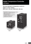
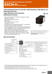
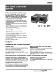
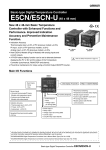
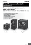
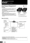
Warning Symbols
E5CC
Specifications
Digital Controller
EN
Instruction Manual
Thank you for purchasing the OMRON E5CC Digital
Controller.
This manual describes the functions, performance, and
application methods needed for optimum use of the product.
Please observe the following items when using the product.
• This product is designed for use by qualified personnel with
a knowledge of electrical systems.
• Before using the product, thoroughly read and understand
this manual to ensure correct use.
• Keep this manual in a safe location so that it is available for
reference whenever required.
OMRON CORPORATION
©All Rights Reserved
a) This product is UL recognized as Open Type Process Control Equipment. It must be mounted in an enclosure
that does not allow fire to escape externally.
b) More than one disconnect switch may be required to de-energize the equipment before servicing.
c) Signal inputs are SELV, limited energy.
d) Caution: To reduce the risk of fire or electric shock, do not interconnect the outputs of different Class 2 circuits.
If the output relays are used past their life expectancy, contact fusing or burning may occasionally occur. Always
consider the application conditions and use the output relays within their rated load and electrical life expectancy.
The life expectancy of output relays varies considerably with the output load and switching conditions.
Loose screws may occasionally result in fire. Tighten the terminal screws to the specified torque of 0.43 to 0.58 N•m.
Set the parameters of the product so that they are suitable for the system being controlled. If they are not suitable,
unexpected operation may occasionally result in property damage or accidents.
A malfunction in the Digital Controller may occasionally make control operations impossible or prevent alarm
outputs, resulting in property damage. To maintain safety in the event of malfunction of the Digital Controller, take
appropriate safety measures, such as installing a monitoring device on a separate line.
Do not allow dirt or foreign objects to enter the jacks on the Digital Controller or cable connector pins. Otherwise,
fire may occasionally occur.
Suitability for Use
Safety Precautions
Key to Warning Symbols
Indicates a potentially hazardous situation which, if
not avoided, is likely to result in minor or moderate
injury or property damage. Read this manual
CAUTION carefully before using the product.
1654637-7
OMRON shall not be responsible for conformity with any standards, codes, or regulations that
apply to the combination of the products in the customer's application or use of the product.
Take all necessary steps to determine the suitability of the product for the systems, machines,
and equipment with which it will be used.
Know and observe all prohibitions of use applicable to this product.
NEVER USE THE PRODUCTS FOR AN APPLICATION INVOLVING SERIOUS RISK TO LIFE
OR PROPERTY WITHOUT ENSURING THAT THE SYSTEM AS A WHOLE HAS BEEN
DESIGNED TO ADDRESS THE RISKS, AND THAT THE OMRON PRODUCT IS PROPERLY
RATED AND INSTALLED FOR THE INTENDED USE WITHIN THE OVERALL EQUIPMENT
OR SYSTEM.
See also Product catalog for Warranty and Limitation of Liability.
Wiring
Dimensions
(48 x number of units -
60 min.
45
+0.6
0
+0.6
0
0 to 20 mA DC
4 to 20 mA DC
Load: 500 Ω max.
Process value or set data type
• Level key
Use this key to change levels:
• No.2 display
Set point, set data read-out value or changed input
value
One relay
output
Pt100
JPt100
Thermocouple
K
Analog
input type
Temperature inputs
J
T
E
L
U
N
R
S
B
W
PL II
10 -70°C
Infrared
Thermosensor 60 -120°C
115 -165°C
ES1B
140- 260°C
4 to 20mA
Current input
0 to 20mA
1 to 5V
Voltage input
0 to 5V
0 to 10V
Setting
0
1
2
3
4
5
6
7
8
9
10
11
12
13
14
15
16
17
18
19
20
21
22
23
24
25
26
27
28
29
Setting range
/-300 to 1500 (°F)
-200 to 850 (°C)
-199.9 to 500.0 (°C) /-199.9 to 900.0 (°F)
/0.0 to 210.0 (°F)
0.0 to 100.0 (°C)
-199.9 to 500.0 (°C) /-199.9 to 900.0 (°F)
/0.0 to 210.0 (°F)
0.0 to 100.0 (°C)
-200 to 1300 (°C) /-300 to 2300 (°F)
-20.0 to 500.0 (°C) /0.0 to 900.0 (°F)
/-100 to 1500 (°F)
-100 to 850 (°C)
-20.0 to 400.0 (°C) /0.0 to 750.0 (°F)
/-300 to 700 (°F)
-200 to 400 (°C)
-199.9 to 400.0 (°C) /-199.9 to 700.0 (°F)
/-300 to 1100 (°F)
-200 to 600 (°C)
/-100 to 1500 (°F)
-100 to 850 (°C)
/-300 to 700 (°F)
-200 to 400 (°C)
-199.9 to 400.0 (°C) /-199.9 to 700.0 (°F)
-200 to 1300 (°C) /-300 to 2300 (°F)
/0 to 3000 (°F)
0 to 1700 (°C)
/0 to 3000 (°F)
0 to 1700 (°C)
/300 to 3200 (°F)
100 to 1800 (°C)
/0 to 3200 (°F)
0 to 2300 (°C)
/0 to 2300 (°F)
0 to 1300 (°C)
/0 to 190 (°F)
0 to 90 (°C)
/0 to 240 (°F)
0 to 120 (°C)
/0 to 320 (°F)
0 to 165 (°C)
/0 to 500 (°F)
0 to 260 (°C)
*6
*6
*6
*6
0
No alarm function
1
Deviation upper/lower limit
-200
stnd
M
Deviation upper limit
Deviation lower limit
ON
OFF
4
Deviation upper/lower range
ON
OFF
5
Deviation upper/lower limit
standby sequence ON
6
Deviation upper limit
standby sequence ON
Deviation lower limit
standby sequence ON
Absolute value upper limit
ON
OFF
ON
OFF
Absolute value lower limit
ON
OFF
10
Absolute value upper limit
standby sequence ON
Absolute value lower limit
standby sequence ON
ON
OFF
PV Change Rate Alarm
14
SP absolute value upper limit
16
ON
OFF
SP
X
SP
L H
SP
L H
SP
X
SP
X
SP
X
0
X
0
X
0
X
0
ON
OFF
ON
OFF
SP absolute value lower limit
MV absolute value upper limit
*6
*6
ON
OFF
ON
OFF
or-r
M
*6
alt1
*6
alh1
*6
alt2
X
*6
SP Lower Limit
*6
X
ON
OFF
ON
OFF
ON
OFF
ON
OFF
18
RSP absolute value upper limit
ON
OFF
19
RSP absolute value lower limit
ON
OFF
CT1
0
ON
OFF
4-20
o2st
4-20
trst
4-20
*6
alh2
X
0
Alarm 4
Type
*3
*4
Alarm 4
0
Hold O down
for at least
3 seconds
(No.1 display flashes,
then the control stops.)
Control Output 1
Signal
Control Output 2
Signal
off
Transfer
Output Signal
Transfer
Output Type
M
*6
Transfer Output
*6
*Voltage output (for driving SSR): 2
*6
*Voltage output (for driving SSR): 2
Direct/Reverse Operation
In Reverse operation (Heating) = or-r
In Direct operation (Cooling) = or-d
Event Input
ev-2
Event Input
*3
ev-3
none
ev-4
*6
sqr
off
*6
amov
0
Move to Advanced
Function Setting
Level
M
Alarm 2 Type:
*3
Specified models only *4
Alarm 2 Hysteresis
0.2
M
X
0
X
0
X
0
X
0
X
0
X
ON
OFF
0
X
0
X
ON
OFF
ON
OFF
0
X
0
X
ON
OFF
ON
OFF
0
X
0
*1: Upper and lower limits can be set for parameters 1, 4 and 5 to
provide for different types of alarm. These are indicated by the
letter "L" and "H".
• The default alarm type is "2"
Conformance to EN/IEC Standards
This is a class A product.
In residential areas it may cause radio interference, in which case the user
may be required to take adequate measures to reduce interference.
Conformance to Safety Standards
Reinforced insulation is provided between input power supply,
relay outputs, and between other terminals.
*3: Refer to the adjoining tables for details of input types and alarm types.
*4: Applicable only to models with alarm functions.
*5: Operation is stopped when moved to the initial setting level.
(control/alarm are both stopped.)
*6: The grayed-out setting items are not displayed for some models and
some settings of other setting items.
*7: Applicable only to models with heater burnout functions.
*8: The four numeric digits of the product code are displayed in the No. 2
display. The setting cannot be changed and there is nothing that you
need to set.
al1l
Auto/Manual Switch
PID 1 control only.
Auto/Manual Select
Addition.
al-2
7
7
Auxiliary output 3
Auxiliary output 2
8
8
Auxiliary output 2
9
9
Auxiliary output 1
Auxiliary output 1
10
10
1
13
2
14
3
15
9
4
16
5
17
10
11
6
18
12
7
8
*4 Input Power Supply
100 to 240 VAC
Communications
Communications (RS-485) Event inputs 1 to 4
(RS-485), CT1, and CT2 and event inputs 3 and 4
B(+)
A(−)
15
B(+)
13
CT1
17
16
CT1
COM
CT2
18
RS-485
14
A(−)
17
B(+)
13
RS-485
14
005
004
15
16
11
12
(no polarity)
003
RS-485
24 VAC/DC
11
Communications
(RS-485) and CT1
A(−)
13
14
006
007
Event inputs 1 and 2, and
transfer output
Event inputs 1 and 2,
and remote SP
13
14
EV1
EV1
15
13
14
15
15
15
16
16
16
16
17
17
17
17
18
18
EV3
18
EV2
EV3
18
EV4
EV4
EV2
EV1
EV2
+
+V
I
13
14
15
+
16
V +
mA 17
−
18
−
Only the value set to the ins: Temperature Input Shift parameter is applied to the entire temperature input range.
When the process value is 200°C, the process value is treated as 201.2°C after input shift if the input shift value
is set to 1.2°C. The process value is treated as 198.8°C after input shift if the input shift value is set to -1.2°C.
l.adj
rsp
*6
sp-m
*6
ct1
*6
ct2
0
0
*6
0
Remote SP Monitor
*6
0
Set Point During
SP Ramp
*6
al-3
Heater Current 1
Value Monitor
(unit: A)
*7
*6
al3h
*6
al3l
*6
al-4
lcr1
0.0
0
lcr2
0.0
0
*6
prst
*6
sktr
*6
r-s
0
*6
Soak Time Remain
*6
o
*6
c-o
0
M
0
0.0
M
al-1
0.0
0
M
0
M
icpt
1
M
wtpt
Operation / Adjustment Protect
Restricts displaying and
modifying menu items in
Operation, Adjustment,
and Manual Control Levels.
Initial Setting / Communication Protect
Restricts movement to the
Initial Setting, Communications
Setting, and Advanced Function
Setting Levels.
off
0.0
hs2
50.0
Setting Change Protect
Restricts changes to settings
by operating the front panel keys.
pfpt
PF Key Protect
Restricts PF key operation.
Monitor (unit: A)
*7
*6
sp-0
*6
sp-1
*6
sp-2
Heater Burnout Detection 2
(unit: A) *7
*6
Leakage Current 1 Value
*6
Monitor (unit: A)
*7
off
M
pmsk
on
M
prlp
0
M
Changed
Parameters Only
Parameter Mask
Enable
Displayed only
when a parameter
mask is set.
Move to Protect
Level
Password to Move
to Protect Level:
M
Restricts which settings can be displayed or changed, and
restricts change by key operation.
Other functions
Refer to the E5CC/E5EC Digital Controllers User’s Manual (Cat. No.
H174) for information on the Advanced Function Setting Level,
Manual Control Level, and other functions.
Refer to the E5CC/E5EC Digital Controllers Communications
Manual (Cat. No. H175) for information on communications.
sp-6
SP 6
0.0
inrt
1.000
rss
0.0
SP 7
HS Alarm 1
(unit: A) *7
*6
p
8.0
*6
*6
Process Value
Input Shift
*6
i
233
Process Value
Slope Coefficient
*6
d
*6
40
Remote SP
Input Shift
*6
SP 0
Coefficient
*6
Proportional
Band
*6
Integral Time
(Unit: secs)
*6
Derivative Time
*6
(Unit: secs)
0
*6
c-i
*6
c-d
8.0
40
Wait Band
off
mv-s
MV at Stop
0.0
mv-e
MV at PV Error
0.0
sprt
SP Ramp Set Value
off
sprl
same
SP Ramp Set Value
(SP Ramp Fall Value)
ol-h
MV Upper Limit
100.0
ol-l
MV Lower Limit
0.0
M
*6
orl
*6
sqrp
0.0
MV Change
Rate Limit
M
Integral Time
(Cooling)
(unit: s)
M
SP 2
wt-b
M
Band
c-p Proportional
(Cooling)
233
Soak Time
1
M
M
SP 1
0
soak
M
*6
M
Hysteresis (Cooling)
1.0
M
M
0
chys
M
M
HS Alarm 2
(unit: A) *7
Hysteresis (Heating)
M
M
Leakage Current 2 Value
*6
Monitor (unit: A)
*7
hys
M
rsrt Remote SP Slope
1.000
during P or PD control.
M
0
ins
50.0
1.0
0
sp-7
Reset Value
of-r Manual
Clears the offset
M
M
M
chgp
*6
0
M
M
Hold O and M keys
down for at least
3 seconds
sp-5
Dead Band
0.0
M
SP 5
M
M
*6
*6
M
M
MV Monitor
(Cooling)
M
off
lcr2
Alarm Value Upper Limit 1
*4
Move to Protect Level
Displayed only when a
password is set. Restricts
moving to Protect Level.
*6
M
*6
Protect Level
oapt
50.0
MV Monitor
(Heating)
M
0
hs1
*6
Operation level should normally be used during operations.
pmov
0.0
*4
Hold O and M keys
down for at least
1 second
Heater Burnout Detection 1
(unit: A) *7
M
Alarm Value
Lower Limit 4 *4
0
al1h
lcr1
SP 4
0
M
M
*6
M
*6
0.0
Alarm Value
Upper Limit 4 *4
M
Alarm Value 1
hb2
*6
M
RUN/STOP
When control start = run
When control stop = stop
*6
M
Alarm Value 4 *4
M
M
*6
al4l
Program Start
0.0
*6
M
rset
run
al4h
*7
ct2 Heater Current 2 Value
Alarm Value
Lower Limit 3 *4
0
Monitor (unit: A)
M
*6
M
Leakage Current 2
Value Monitor
(unit: A)
*7
M
*6
0.0
Alarm Value
Upper Limit 3 *4
M
Leakage Current 1
Value Monitor
(unit: A)
*7
M
*6
hb1
sp-4
c-db
M
M
M
*6
M
*6
*6
ct1 Heater Current 1 Value
Alarm Value 3 *4
*6
M
M
0.0
SP 3
0
M
lsp
0
Heater Current 2
Value Monitor
(unit: A)
*7
at-1
spmd SP Mode
*6
M
*6
M
*6
sp-3
M
off
Alarm Value
Lower Limit 2 *4
M
M
*6
al2l
40%AT Execute
cmwt Communications Writing
Alarm Value
Upper Limit 2 *4
M
M
0.0
al2h
Press O
(less than
1 second)
*6
AT Execute / Cancel
M
*6
Alarm Value 2 *4
M
Multi-SP Set Point
Selection
M
0.0
0
Adjustment Level
Displayed only once when
entering Adjustment Level.
at 100%AT Execute at-2
off
Alarm Value
Lower Limit 1 *4
M
*6
0.0
Event Input
Extraction of Square
Root Enable
(Only when analog
input is set)
Auxiliary outputs 1 and 2 Auxiliary outputs 1, 2, and 3
+Q
−Q
+
12
M
M
Event Input
Assignment 3
M
Alarm 1 Hysteresis
*6
none Assignment 4
M
The E5CC is set for a K thermocouple (input type of 5)
by default. If a different sensor is used, an input error (s.err) will occur.
Check the setting of the Input Type parameter.
*3 Auxiliary Outputs
V
4
5
6
*6
Process Value/Set Point
s.err is displayed when *6
connected sensor is
different from input type.
M
stop Assignment 2
M
*6
m-sp
msp0 Assignment 1
M
Control Period (Cooling)
(Unit: Seconds)
*6
0.0 Lower Limit
ev-1
1. Control outputs 5. Options
002
18
M
Transfer Output
M
M
Control Period (Heating)
(Unit: Seconds)
a-m
100.0 Upper Limit
M
Program Pattern
M
*6
0
Hold O down
for at least
1 second
0
ON
OFF
Transfer output
Adjustment Level
25
M
tr-t
14
1
2
3
+
−
Alarm 3
0.2 Hysteresis
o1st
1
2
3
+
−
*8
M
0
X
X
alh4
tr-l
*6
2 Specified models only *4
2
2
ST (Self-Tuning)
M
0
alt4
tr-h
Alarm 1 Type:
Memory protection
POWER ON
0.2 Hysteresis
Standard control = stnd
*6
Heating and cooling control = h-c
(Select standard control or heating
and cooling control as required)
0.2
SP
X
alh3
M
M
SP
X
ON
OFF
20
orev
SP
Vary with
"L", "H" values
ON
OFF
c-cp
M
Vary with
"L", "H" values
ON
OFF
20
Installation environment
QQ
Operation Level
M
M
X
SP
X
cp
Weight
Degree of protection
Two voltage outputs
(for driving SSRs)
Check the wiring before turning ON the power supply.
*3
*4
M
ST ON = on
on ST OFF = off
off
2
Alarm 3
Type
Initial setting level enables users to specify their preferred
operating conditions (input type, alarm type, control method, etc.)
MV absolute value lower limit
17
X
LBA (only for alarm 1)
13
15
*6
*6
SP Upper Limit
alt3
M
M
Vary with
"L", "H" values
L H
ON
OFF
ON
OFF
9
12
st
ptrn
Output off
ON
OFF
3
11
*6
cntl PID/ONOFF
In ON/OFF control = onof *6
onof In 2-PID control = pid
M Standard or Heating/Cooling
s-hc
Altitude
Recommended fuse
* When complying with EMC standards, the line connecting the sensor must be 30 m or less.
If the cable length exceeds 30 m, compliance with EMC standards will not be possible.
M
M
Alarm output function
2
8
Scaling Lower Limit
(only when setting
0 analog input)
M
Point
dp Decimal
(only when setting
0 analog input)
M Temperature °C= c
°F= f
d-u Unit
c (C stands for Celsius,
F for Fahrenheit)
M
in-l
sl-l
Positive alarm value (X) Negative alarm value (X)
ON
OFF
7
*6
M
Alarm type
EV2
Lit when the Auto/Manual Mode is set
M
M
Use the following ranges for scaling: -1999
to 9999, -199.9 to 999.9, -19.99 to 99.99,
-1.999 to 9.999
SP
*1
Scaling Upper Limit
(only when setting
100 analog input)
1300
*6
*1
in-h
sl-h
Alarms
*1
*6
M
*The default is“5”.
*s.err will be displayed when a platinum resistance thermometer is mistakenly connected
while input type is not set for it. To clear the s.err display, correct the wiring and cycle the
power supply.
Setting
Input Type *3
13
EV1
• MANU: Manual output indicator
Operation stopped.
(Control/alarm are both stopped.)
5
M
Event inputs 1 and 2,
and CT1
ON (disables the Up and Down Keys).
Flashing during self-tuning.
Lit during auto-tuning.
*5
in-t
*5 Options
001
Lit when Setting Change Protect is
• TUNE:
1
2
3
*2 Sensor Temperature/Analog Input
TC
Pt
I
+ 4
4
4
mA
−
− 5
5
5
−
V
6
6
+ 6
+
:Protection indicator
to Manual Mode.
Initial Setting Level
Input
Lit when the assigned function is ON.
CX
One linear
current output
One voltage output
(for driving SSR)
1
2
3
Lit when communications writing is enabled and not lit
when it is disabled.
• RSP: Remote SP indicator
•
Each press of U key increments or advances the
values displayed on the No.2 display.
Each press of D key decrements or returns the
values displayed on the No.2 display.
Operation Menu
Input type
Platinum
resistance
thermometer
• STOP: Control stopped indicator
• SUB1: Auxiliary output 1 indicator
The RST indicator lights when an event or key
operation changes the RUN/STOP parameter to STOP
• SUB2: Auxiliary output 2 indicator
during operation. Operation other than the control
• SUB3: Auxiliary output 3 indicator
outputs continues even when control is stopped.
• OUT1: Control output 1 indicator • CMW: Communications writing
• OUT2: Control output 2 indicator
enabled/disabled indicator
• Up and Down keys
Input Type
Ambient humidity
Storage temperature
Relay outputs
250 VAC, two outputs: 3 A
(resistive load)
250 VAC, three outputs: 2 A
(resistive load)
Control output 2
Voltage output (for driving SSR)
12 VDC, 21 mA
*1 Control Outputs 1 and 2
RX
QX
Operation indicators
• No.1 display
The default PF Setting parameter is for shifting the digit.
This is a function key. When it is pressed, the function
set for the PF Setting parameter will operate.
Ambient temperature
Auxiliary outputs 1, 2, and 3
Current output
45
• °C / °F : temperature unit
• Shift key (PF key)
Control method
Auxiliary outputs
E5CC
250 VAC, 3 A (resistive load)
Names of Parts on Front Panel
• Press the O key and the M key together for at
least 3 seconds to switch to protect level.
Control output 2
Relay output
Voltage output (for driving SSR)
12 VDC, 21 mA
• To install the Digital Controller, insert it into a square hole in a panel with a thickness of 1 to 5 mm, and then
insert the enclosed adapter so that it locks into the groves on the top and bottom of the rear case.
• Tighten the two mounting screws on the top and bottom of the adapter to keep them balanced, and finally
tighten them to a torque of between 0.29 and 0.39 N·m.
• Make sure that the surrounding temperature does not exceed the allowable operating temperature given in the
specifications especially when two or more Controllers are mounted.
* The main unit can be removed for maintenance without disconnecting the terminal wiring.
* Do not remove the terminal block. Doing so may result in failure or malfunction.
* A Setup Tool port is provided on the bottom of the product. Use this port to connect a personal computer to the product when using the Setup Tool.
E58-CIFQ1 USB-Serial Conversion Cable is required to connect the personal computer to the product. (Do not use the product with the
USB-Serial Conversion Cable left permanently connected.)
Refer to the instruction manual provided with the USB-Serial Conversion Cable for details on connection methods.
Press this key to change the contents of the display.
Press this button for 1 s or longer for reverse scroll.
Control output 1
Control output 1
+1
2.5) 0
+0.6
0
58
Solderless terminal size: M3
Terminal cover: E53-COV17
USB-Serial Conversion Cable (Sold Separately) (E58-CIFQ1)
• Mode key
Remote SP input
Side-by-side mounting (waterproof not possible) (mm)
To install the Controller so
that it is waterproof, insert
the Waterproof Packing.
Controllers cannot be
waterproofed when they
are mounted side by side.
44.8
The temperature unit is displayed when the displayed value
is a temperature. Either C or F is displayed according to
the set value of the temperature unit.
Event input
Contact input
No-contact input
Do not connect anything to the terminals that are shaded gray.
Individual mounting (mm)
45
(64)
60
4
1.5
48
Indication accuracy
(Ambient temperature: 23°C)
100 to 240 VAC, 50/60 Hz or
24 VAC, 50/60 Hz / 24 VDC
85 to 110% of the rated voltage
Option 000:
Approx. 4.1 VA (100 to 240 VAC)
Approx. 3.0 VA (24 VAC)/approx. 1.7 W (24 VDC)
All other specifications:
Approx. 5.1 VA (100 to 240 VAC)
Approx. 3.9 VA (24 VAC)/approx. 2.3 W (24 VDC)
Thermocouple:
(±0.3 % of indication value or ±1°C,
whichever is greater) ±1 digit max.
Platinum resistance thermometer:
(±0.2 % of indication value or ±0.8°C,
whichever is greater) ±1 digit max.
Analog input:
±0.2 % FS ±1 digit max.
Output current: approx. 7 mA per contact.
ON:1 kΩ max., OFF: 100 kΩ min.
ON: residual voltage 1.5 V max.,
OFF: leakage current 0.1 mA max.
4 to 20 mA DC or 0 to 20 mA DC
0 to 5 V DC or 0 to 10 V DC
Relay output :SPST-NO
250VAC, 3A(resistive load)
Electrical life of relay: 100,000 operations
Voltage output (for driving SSR):
12 VDC ±20%, 21 mA
Current output: 4 to 20 mA DC, 0 to 20mA DC
Load: 500 Ω max.
(Long-life model: 1 million operations)
Voltage output (for driving SSR):
12 VDC, 21 mA
ON/OFF or 2-PID control
Relay outputs:SPST-NO, 250 VAC,
3 A (resistive load), Electrical life of relay:
100,000 operations
-10 to 55°C
(Avoid freezing or condensation)
RH25 to 85%
-25 to 65°C
(Avoid freezing or condensation)
Max. 2,000m
T2A, 250 VAC, time-lag,
low-breaking capacity
Approx. 120 g (Digital Controller only)
Front panel: IP66
Rear case: IP20, Terminal section: IP00
Installation category II, pollution
degree 2 (as per IEC61010-1)
Non-volatile memory
(Number of write operations: 1,000,000)
4 to 20 mA DC with load of 500 Ω max.
1 to 5 VDC with load of 1 kΩ min.
Connections (The applicability of the electric terminals varies with the type of machine.)
Installation
In the pack:
*Main unit
*Watertight packing
*Adapter
*Instruction manual
*Terminal cover (Provided only for models with “-500” suffix only)
Dimensions (mm)
Operating voltage range
Power consumption
Be sure to observe the following precautions to prevent operation failure, malfunction, or adverse affects on the
performance and functions of the product. Not doing so may occasionally result in unexpected events.
Use the product within specifications.
(1) The product is designed for indoor use only. Do not use the product outdoors. Do not use or store the
product in any of the following locations.
•Places directly subject to heat radiated from heating equipment.
•Places subject to splashing liquid or oil atmosphere.
•Places subject to direct sunlight.
•Places subject to dust or corrosive gas (in particular, sulfide gas and ammonia gas).
•Places subject to intense temperature change.
•Places subject to icing and condensation.
•Places subject to vibration and large shocks.
(2) Use/store within the rated temperature and humidity ranges.
Provide forced-cooling if required.
(3) To allow heat to escape, do not block the area around the product.
Do not block the ventilation holes on the product.
(4) Be sure to wire properly with correct polarity of terminals.
(5) Use the specified size of crimped terminals (M3, width 5.8 mm or less) for wiring. To connect bare wires to
the terminal block, use copper braided or solid wires with a gage of AWG24 to AWG18 (equal to crosssectional area of 0.205 to 0.8231 mm2). (The stripping length is 6 to 8 mm.) Up to two wires of same size
and type, or two crimped terminals can be inserted into a single terminal.
(6) Do not wire the terminals which are not used.
(7) Allow as much space as possible between the controller and devices that generate a powerful highfrequency or surge.
Separate the high-voltage or large-current power lines from other lines, and avoid parallel or common wiring
with the power lines when you are wiring to the terminals.
(8) Use this product within the rated load and power supply.
(9) Make sure that the rated voltage is attained within two seconds of turning ON the power using a switch or
relay contact. If the voltage is applied gradually, the power may not be reset or output malfunctions may
occur.
(10) Make sure that the Digital Controller has 30 minutes or more to warm up after turning ON the power before
starting actual control operations to ensure the correct temperature display.
(11) When executing self-tuning, turn the load and the unit ON simultaneously, or turn the load ON before you
turn the controller ON.
(12) A switch or circuit breaker should be provided close to this unit.
The switch or circuit breaker should be within easy reach of the operator, and must be marked as a
disconnecting means for this unit.
(13) Do not use paint thinner or similar chemical to clean with. Use standard grade alcohol.
(14) Design system (control panel, etc) considering the 2 second of delay that the controller’s output to be set
after power ON.
(15) The output may turn OFF when shifting to certain levels. Take this into consideration when performing
control.
(16) The number of non-volatile memory write operations is limited. Therefore, use RAM write mode when
frequently overwriting data during communications or other operations.
(17) When disassembling the Temperature Controller for disposal, use suitable tools.
(18) Do not exceed the communications distance that is given in the specifications and use the specified
communications cable. Refer to the E5CC/E5EC Digital Controllers User’s Manual (Cat. No.H174) for the
communications distance and cable specifications.
Do not touch the terminals while power is being supplied.
Doing so may occasionally result in minor injury due to electric shock.
Do not allow pieces of metal, wire clippings, or fine metallic shavings or filings from installation to
enter the product. Doing so may occasionally result in electric shock, fire, or malfunction.
Do not use the product where subject to flammable or explosive gas. Otherwise, minor injury from
explosion may occasionally occur.
Never disassemble, modify, or repair the product or touch any of the internal parts. Minor electric
shock, fire, or malfunction may occasionally occur.
CAUTION - Risk of Fire and Electric Shock
Refer to the E5CC/E5EC Digital Controllers User’s Manual (Cat. No. H174)
for detailed application procedures.
Power supply voltage
Precautions for Safe Use
CAUTION
0.0
Extraction of Square
Root Low-cut Point
M
Derivative Time
(Cooling)
(unit: s)
M
Adjustment level is for entering set
values and shift values for control.
Error Display (troubleshooting)
When an error has occurred, the No.1 display shows the error code. Take necessary measure
according to the error code, referring the table below.
Status at error
No.1 display
Meaning
s.err (S. Err)
Input error
*2
e333 (E333)
e111
(E111)
Action
Check the setting of the Input Type parameter,
check the input wiring, and check for broken or
shorts in the temperature sensor.
A/D converter error
*2
After the correction of A/D converter error, turn the
power OFF then back ON again. If the display
remains the same, the controller must be repaired.
If the display is restored to normal, then a
probable cause can be external noise affecting the
control system. Check for external noise.
Memory error
Turn the power OFF then back ON again. If the
display remains the same, the controller must be
repaired. If the display is restored to normal, then
a probable cause can be external noise affecting
the control system. Check for external noise.
Control
output
Alarm
OFF
Operates
as above the
upper limit.
OFF
OFF
OFF
OFF
If the input value exceeds the display limit (-1999 to 9999), though it is within the control
range, [[[[ will be displayed under -1999 and ]]]] above 9999. Under these conditions,
control output and alarm output will operate normally.
Refer to the E5CC/E5EC Digital Controllers User’s Manual (Cat. No. H174) for the controllable
ranges.
*2: Error shown only for "Process value / Set point". Not shown for other status.
OMRON EUROPE B.V.
Wegalaan 67-69, NL-2132 JD Hoofddorp The Netherlands
Phone 31-2356-81-300
FAX 31-2356-81-388
OMRON ELECTRONICS LLC
One Commerce Drive Schaumburg, IL 60173-5302 U.S.A
Phone 1-847-843-7900
FAX 1-847-843-7787
OMRON ASIA PACIFIC PTE. LTD.
No. 438A Alexandra Road # 05-05/08 (Lobby 2),
Alexandra Technopark, Singapore 119967
Phone 65-6835-3011
FAX 65-6835-2711
OMRON Corporation
Shiokoji Horikawa, Shimogyo-ku, Kyoto 600-8530 JAPAN