1
VoIP Phone
Model EP-8201
User Manual
Release 1.2
Table of Content
EP-8201 User Manual
Overview .................................................................................................................. 1
1.1
VoIP Phone Features ......................................................................................... 2
1.2
Front View ...................................................................................................... 3
1.3
Bottom View .................................................................................................... 3
1.4
Structure ........................................................................................................ 4
Installation ................................................................................................................ 5
2.1
Package Contents ............................................................................................. 5
2.2
Setting Up EP-8201 ........................................................................................... 6
2.3
Acquiring Network Port IP Addresses ...................................................................... 7
2.4
Accessing the Built-in Web Server .......................................................................... 8
Web Configuration ..................................................................................................... 11
4.1
Status Page .................................................................................................. 12
4.2
Configuration Page .......................................................................................... 12
3.2.1
Preference ................................................................................................. 13
3.2.2
Network Configuration ................................................................................... 15
3.2.3
Call Settings ............................................................................................... 17
3.2.4
Phone Settings ............................................................................................ 26
3.2.5
Save Changes ............................................................................................ 28
3.2.6
Discard Changes ......................................................................................... 28
4.3
Phone Book .................................................................................................. 28
3.3.1
Edit a Phone Book Entry ................................................................................ 29
3.3.2
Delete a Phone Book Entry ............................................................................. 30
3.3.3
Add a Phone Book Entry ................................................................................ 30
3.3.4
Backup / Restore Phone Book ......................................................................... 30
3.3.5
Auto Update ............................................................................................... 31
4.4
Tools ........................................................................................................... 31
3.4.1
Tools ........................................................................................................ 32
3.4.2
Change Password ........................................................................................ 32
3.4.3
Backup / Restore Configurations ....................................................................... 33
3.4.4
Reset Configuration ...................................................................................... 33
3.4.5
Reboot ...................................................................................................... 33
4.5
Gain Settings ................................................................................................. 33
Phone Menu ............................................................................................................. 36
4.1
Call History ................................................................................................... 37
4.2
Phone Book .................................................................................................. 38
4.3
Message Center ............................................................................................. 38
4.4
System Tools ................................................................................................. 39
4.5
Device Config ................................................................................................ 40
Phone Operation ....................................................................................................... 41
5.1
Making a Call ................................................................................................. 41
5.2
Making a Hands-Free Call ................................................................................. 41
5.3
Answering an Incoming Call ............................................................................... 42
5.4
Dialing from the Phonebook ............................................................................... 42
5.5
Viewing / Dialing from the Call History ................................................................... 42
5.6
Redialing the Last Number ................................................................................. 42
5.7
Speed Dial .................................................................................................... 43
5.8
Putting / Releasing a Call on Hold ........................................................................ 43
5.9
Transferring a Call ........................................................................................... 43
5.10 Answering a Call Waiting Call ............................................................................. 44
5.11 Adjusting the Ringing Volume ............................................................................. 44
5.12 Adjusting the Handset Receiver Volume................................................................. 44
5.13 Adjusting the Speaker Volume ............................................................................ 44
5.14 Adjusting the LCD Contrast ................................................................................ 45
5.15 Resetting Phone Configuration ............................................................................ 45
i
Overview
EP-8201 User Manual
1
Overview
The EP-8201 VoIP Phone is fully compatible with the open SIP industry standards. This
feature-rich VoIP Phone is designed as an enterprise grade VoIP device to work seamlessly
with most of the existing SIP systems.
Figure 1-1
EP-8201 VoIP Phone
1
Overview
EP-8201 User Manual
1.1 VoIP Phone Features
The EP-8201 VoIP Phone has the following features:
Standard SIP
Standard Protocols: TCP/UDP/IP, RTP, HTTP, HTTPS, ARP, DNS, DHCP, NTP/SNTP, FTP,
TFTP, and SSL
VoIP Speech codecs: including G.711 a-law and u-law, GSM, G.723.1, G.729a/b/ab
Interoperable with various 3rd party VoIP end user devices, Proxy/Registrar/Server, and
gateway products
Up to 4 SIP registrations (same server or different servers) with BASIC or DIGEST
authentication (MD5, MD5-sess)
Full-duplex Speakerphone with echo cancellation
Handsfree operation via speakerphone or headset mode
Standard phone features: Caller ID Display, Call Waiting, Call Hold, Call Transfer, Call
Forward, Call Conference, Call History, Speed Dial, Phonebook
Special phone features: Dial Plan, Hotline, Voice Mail
DTMF modes: In-band and out-of-band DTMF (RFC2833/SIP INFO) dialing
Dial Plan
128 x 64 dot matrix LCD (sixe: 4 cm x 7 cm) with backlight and 4-level contrast controls
4 ring types, 6 ringing levels (including silence level)
6-level volume controls for both speakerphone and headset modes
DHCP Client, Static IP, PPPoE support for the LAN Port
Built-in network switch or router for the PC Port
Backup Server support for Single Server Mode
Jitter Buffer, VAD, CNG and PLC
Redundant DNS support
QoS Support (ToS / VLAN)
Built-in Web Server for Device Configuration
Built-in Phone Menu
Auto Firmware Upgrade and Phonebook Update
Auto Provisioning via http/ftp/tftp
2
Overview
EP-8201 User Manual
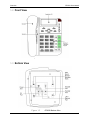
1.2 Front View
Figure 1-2
EP-8201 Front View
1.3 Bottom View
Figure 1-3
EP-8201 Bottom View
3
Overview
EP-8201 User Manual
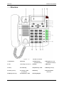
1.4 Structure
Figure 1-4
EP-8201 Structure
1 Hook Switch
6 Hold key
11 Redefine keys
(R1/R2/R3/R4/R5)
16 Navigator keys (UP/
DOWN/LEFT/RIGHT)
2 LCD
7 Conf. key (Conference)
12 Redial
17 Menu key
3 OK key
8 Transfer key
13 Speaker key + LED
18 ESC key (Escape)
4 Del key (Delete)
9 Line keys + LED
(L1/L2/L3/L4)
14 Mute key
19 Visual Indicator
(Red LED)
5 Msg key (Message)
10 Headset key + LED
15 Dialing Keypad
4
Installation
EP-8201 User Manual
2
Installation
Please follow the steps below to prepare and install the EP-8201.
1. Unpacking the EP-8201 gift box.
2. Checking the contents as described in Section 2.1.
3. Connecting the EP-8201 as described in Section 2.2.
4. Powering up the EP-8201.
5. Acquiring EP-8201 Phone IP address.
6. Configuring EP-8201 via Web Browser.
7. Configuring EP-8201 via Phone Menu (Basic settings only).
2.1
Package Contents
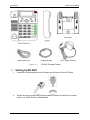
EP-8201 is shipped with the following items as shown in Figure 2-1 below:
1. One EP-8201 main Boad
2. One Handset
3. One Coild Handset cord
4. One Base Stand
5. One Ethernet Cable
6. One AC/DC Adapter - 12VDC/500mA Output (Optional)
Note: This is not required if your network switch supports POE.
5
Installation
EP-8201 User Manual
Figure 2-1
2.2
EP-8201 Package Content
Setting Up EP-8201
1.
Connect the coiled telephone cord to handset and the base of the VoIP Phone.
2.
Use the enclosed (or equivalent) Ethernet cable to connect the LAN port to a hub or
switch, or to a DSL Router or Cable Modem.
6
Installation
EP-8201 User Manual
3.
If network does not support PoE, connect the power supply to the DC Jack on the
bottom of the EP-8201 (Use the one enclosed or equivalent).
4.
For the first time installation, the phone will scan the network for available services
which are DHCP, PPPoE, and Fixed IP. Select the preferred service and enter the
required information if needed. No user input is required for DHCP service. User ID
and Password are required for PPPoE. IP address, Netmask, and Gateway IP
Address are required for Fixed IP mode.
2.3
Acquiring Network Port IP Addresses
Once the EP-8201 is properly setup and powered up, the IP Addresses assigned to the LAN
port and PC port can be retrieved via the Phone Menu as described below.
Press
Press
(System Tools).
Press
(Phone Status).
Press
(LAN Port) to view the LAN port IP.
.
The phone LCD displays:
LAN PORT
• STATUS: WORKING.
• IP: xxx.xxx.xxx.xxx
where xxx is any valid IP address between 0 and 255.
Or Press
(PC Port) to view the PC port IP. If the PC port is set to Bridge
Mode, there is no IP address assigned. In this case, a PC connected to this port is in
the same network segment as the LAN port.
7
Installation
2.4
EP-8201 User Manual
Accessing the Built-in Web Server
The built-in Web Server can be accessed by entering the LAN / PC IP address in a web
browser. Please see below to determine which IP Address to be used to access the built-in
Web Server.
Use LAN Port IP address when:
1. A PC and the LAN port are connected to the same network segment. This condition
applies to a PC connected to the PC port when it is set to Bridge Mode.
2. LAN IP address is public and the PC has internet access.
Note: If a private IP is assigned to the LAN port, it may still be accessed from the internet
provided that the local router is set up properly. Please consult your network administrator for
more information.
Use PC Port IP address when:
1. The PC Port is set to Fixed IP mode and a PC is connected to the same network
segment. Please make sure that the PC IP is setup properly.
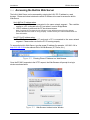
To access the built-in Web Server, type the proper IP address (for example: 192.168.2.124 or
http://192.168.2.124 in the address field of a Web Browser (IE, Firefox, etc.).
Figure 2-2
Entering Phone IP Address to a Web Browser
Once the EP-8201 responds to the HTTP request, the Web Browser will prompt for a login
window as shown below.
Figure 2-3
Web Browser Authentication Window
8
Installation
EP-8201 User Manual
EP-8201 supports two login levels.
For Administrator, please enter User name = “admin” and Password = “admin” (factory
default).
For User, please enter User name = “user” and the Password = “1234” (factory default).
Both passwords can be changed in the Administrator mode. Only user password can be
changed in the User mode. Please keep a record of the new passwords if changed. There is a
Star Command to reset the passwords to the factory defaults (Please see section x.xx for more
information).
The Administrator mode allows full access to the built-in Web Server whereas the User mode
restricts the user from accessing the Call Settings page.
9
Web Configuration
EP-8201 User Manual
3
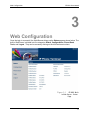
Web Configuration
Once the login is successful, the Web Browser brings up the Status page as shown below. The
built-in Web Server is divided into five categories: Status, Configurations, Phone Book,
Tools, and Logout. They can be access by clicking on the left hand menu column.
Figure 3-1
EP-8201 Builtin Web Server – Status
Page
11
Web Configuration
EP-8201 User Manual
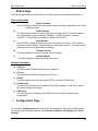
4.1 Status Page
The Status page provides a brief summary on the Phone (Device) and Network information.
Phone Information
a)
Profile X Number
Up to 4 Profiles can be defined; each profile contains one phone registration to the same
or different server.
b)
Profile X Status
This field shows the status of server registration for each profile. If the device registers
to the designated server successfully, it displays “LOGIN”; otherwise, it displays
“LOGOUT”. If the profile is not defined, it display “NO CONFIG”.
c)
Serial Number
Each EP-8201 is assigned with a unique serial number by the factory. This number is
important for auto provision, technical support, and warranty service. This serial number
is also printed on the product label at the bottom.
d)
Firmware Version
This field identifies the current Firmware Version installed.
e)
Hardware Model
This field identifies the hardware model and version.
Network Information
a)
LAN Port
This field shows IP address assigned to the LAN port.
b)
PC Port
This field shows IP address assigned to the PC port.
c)
PPPoE
This field shows the dial up status when PPPoE is enabled for ADSL login.
d)
Default Route
The Default Route shows the IP address of the default gateway / router that is used in
the current network environment.
e)
DNS Server
This field shows the IP address of the DNS server to be used for domain name
interpretation.
4.2 Configuration Page
To access the Configurations page, click on the “Configurations” tab on the left hand column.
This brings up all the pages under this tab: Preference, Network, Call Settings, and Phone
Settings.
12
Web Configuration
EP-8201 User Manual
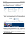
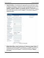
3.2.1 Preference
This page configures the general settings in the device: Language, Time Zone, Display SIP
Server Time, Time server, Time Format, Auto-Provision, Key(#), Phone Book Mode,
Network Tones, Speaker Phone Mic Input Gain, and Central Management.
Figure 1-1
Configurations Page – Preference
a) Language - This field sets the language to be used for initial access to the built-in Web
Server. The languages currently available for selection are English and 简体中文(Simplified
Chinese). Once the language change is saved, it does not take effect until the web server
restarts.
Figure 1-2
Webpage Language Selection
To change the display language immediately, you can select the language icon located at
the top right hand corner (as shown below). However, this does not change the default
language.
Figure 1-3
Viewing Language Selection
b) Time Zone – This parameter specifies your local time zone in order for the date/time to be
correctly displayed since the date/time obtained from a network time server is referenced to
the Greenwich Mean Time (GMT). If your time zone is 8 hours ahead of the GMT, you need
to enter the value “GMT+8” in this field.
c) Display SIP Server Time – This parameter enables the phone to receive the data/time
information from the designated SIP Server. If this is enabled, the Time Server parameter
below will be disabled automatically.
13
Web Configuration
EP-8201 User Manual
d) Time Server – This parameter specifies the location of the network time server for obtaining
the date and time information. It accepts both domain name and IP address. If the Display
SIP Server Time is enabled, this parameter is disabled automatically.
e) Time Format – This specifies the display time format (12-hour or 24-hour).
f)
Auto Provision – This parameter enables or disables the Auto Provision procedures. The
Auto Provision is a batch script to obtain configuration and firmware upgrade information
from a server. Once this option is enabled, two additional parameters (Provision Server
and Provision Interval) are displayed. The Provision Server specifies the location of the
designated provision server. The auto provision procedure is executed at boot up time and
is repeated at a duration specified in the parameter Provision Interval.
Figure 1-4
Auto Provision Setting
g) Key(#) – When dialing a VoIP number, the VoIP device needs to wait for the user to
c8omplete the number dialing before the call request is actually sent to the server. This
parameter enables or disables the “#” key to be used to signal the number dialing is
completed and the call request can be execute immediately.
h) Phone Book Mode – This parameter defines if one phone book is used for all four profiles
(Global) or for each profile (By Line).
i)
Network Tones – This parameter defines the network tones to be used. The predefined
networks tones are: China, Hong Kong, Taiwan, New Zealand, United Kingdom, United
States, Korea, Slovenia, Czechoslovakia, India, Singapore, Israel, Malaysia, Indonesia,
Thailand, Romania, Bangladesh, and Customized. The Customized option allows user
to define his own network tones. If the desired network tones selection is not available, user
can use this Customized option.
Figure 1-5
Network Tones Setting
Each network tone is defined as
nc, rpt, c1on, c1off, c2on, c2off, c3on, c3off, f1, f2, f3, f4, p1, p2, p3, p4,
where nc is the number of cadences
rpt is the repeat counter(0 - infinite, 1~n - repeat 1~n times)
c1on is the cadence one on duration (in milliseconds)
c1off is cadence one off duration (in milliseconds)
14
Web Configuration
EP-8201 User Manual
c2on is the cadence two on duration (in milliseconds)
c2off is the cadence two off duration (in milliseconds)
c3on is the cadence three on duration (in milliseconds)
c3off is the cadence three off duration (in milliseconds)
f1 is the tone #1, 300-3000(Hz)
f2 is the tone #2, 300-3000(Hz)
f3 is the tone #3, 300-3000(Hz)
f4 is the tone 34, 300-3000(Hz)
p1 is the attenuation index for tone #1, 0~31(0=3dB, -1dB increments)
p2 is the attenuation index for tone #2, 0~31(0=3dB, -1dB increments)
p3 is the attenuation index for tone #3, 0~31(0=3dB, -1dB increments)
p4 is the attenuation index for tone #4, 0~31(0=3dB, -1dB increments)
Two examples of network tone definition are shown below.
1. A New Zealand Dial Tone (400 Hz) is defined as 0,0,0,0,0,0,0,0,400,0,0,0,10,0,0,0.
2. A New Zealand Busy tone (400Hz with a cadence of 500ms on and 500ms off (repeat)) is
defined as 1,0,500,500,0,0,0,0,400,0,0,0,10,0,0,0.
j)
Speakerphone Mic Input Gain – This parameter is intended to tune the Speakerphone
performance. Increase the Mic gain if the volume heard at the other party is low. Reduce
the Mic gain if the echoes or howling occurs locally.
k) Centralized Management – This is a proprietary protocol to support remote management of
the EP-8201. Please consult your local agent or representative for more information.
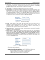
3.2.2 Network Configuration
This page configures the network interface for the LAN Port and the PC Port.
Figure 1-6
Network Configuration
LAN Port
The LAN port is intended for internet access. It is normally connected to a network device
(router or ADSL modem) for internet access. Three operational modes are supported.
15
Web Configuration
EP-8201 User Manual
Figure 1-7
LAN Port Setting (Mode Selection)
•
DHCP – This mode should be selected If the network device functions as a DHCP host, This
allows the HT-812P to obtain all related network information / settings from the DHCP host.
•
Static IP – This mode sets the LAN port IP manually which can either be a public or private
IP. Other network settings (Subnet Mask, Default Route, Primary DNS, Secondary DNS)
should also be entered accordingly.
Figure 1-8
•
LAN Port Setting (Static IP)
PPPoE – This selection is intended for broadband connection (ADSL / Cable modem) that
requires dial up / authentication using PPPoE protocol. Both User Name and Password
are required. Please consult your service provider for more information if needed. One
advantage with the PPPoE dial up is that the IP address obtained for the LAN port is
normally a public IP.
16
Web Configuration
EP-8201 User Manual
Figure 1-9
LAN Port Setting (PPPoE)
More advanced parameters for 802.1q VLAN and MAC settings are available. Please consult
your network administrator for assistance if needed.
PC PORT
The PC port is intended to provide an Ethernet connection to other network devices (for
example: PC, network HUB.). Two modes of operation are available:
1. Bridge mode - This mode allows the network traffics at the PC port to be bypassed to LAN
port. This means that the network device share the same network segment as the LAN
port. There is no IP address assigned to the PC port.
2. Fixed IP - This mode sets the PC port IP Address (private IP) and Subnet Mask manually.
This creates a new network segment for the network devices connected to the PC Port.
Figure 1-10
PC Port (Fixed IP)
To simplify network IP assignments, enable the DHCP Server for the PC Port. This allows
network devices connected Port to obtain network IP and related information from the PC
Port. Please consult your network administrator for proper settings of the DHCP Server
Figure 1-11
PC Port DHCP Host Setting
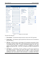
3.2.3 Call Settings
The Call Settings page configures all related settings for VoIP Service. The EP-8201 is SIP
compliant and it supports up to 4-line appearances in two registration modes: Single Server
and Multiple Servers.
17
Web Configuration
1.
EP-8201 User Manual
Single Server Mode – This mode allows SIP registrations to only one SIP Server / Proxy;
however, it can support up to 4 registrations of different SIP numbers and names (referred
as “Contact” in the webpage). A backup server option is available and it will be used once
registration to the primary server fails. Line 1 to Line 4 keys are predefined for the
“Contact1”, “Contact2”, “Contact3”, and “Contact4” respectively. This allows the user to
specify which identity (Contact: SIP number and name) will be used for the call. The default
is to use the contact information for Line1 (“Contact1”). Below shows the webpage for
Single Server Mode.
Figure 1-12
2.
Single SIP Server Mode
Multiple Server Mode – This mode allows up to 4 SIP registrations to up to 4 different SIP
servers / proxies as shown below. Each registration is referred as a “Profile”. Line 1 to
Line 4 keys are predefined for Profile 1 to 4 respectively. If a “Profile” is not defined, the
corresponding Line key is disabled. If a call is made without pressing a Line key, the
default line to be used is Line 1 (Profile 1). Below shows the webpage for Multiple
Server Mode.
18
Web Configuration
EP-8201 User Manual
Figure 1-13
Multiple SIP Server Mode
The basic SIP settings are:
1.
Phone Number – This parameter assigns the phone number used for SIP registration.
2.
Display Name – This parameter (optional) specifies the Caller name and is transmitted as
part of the caller ID.
3.
SIP Proxy – A SIP Proxy acts as a call manager of all incoming and outgoing calls. Specify
the location (IP address / domain name) of the designated SIP Proxy used for SIP service.
The standard port used is 5060. To specify a non-standard signaling port, add “:<port
number>” to the of the location. For example: If SIP Proxy = yoursippbx.com, the signaling
port is the standard port 5060. If SIP Proxy = yoursippbx.com:15060, the signaling port is
15060.
4.
SIP Registrar – A SIP Registrar maintains a database of all SIP phones registered and
their contact information. Specify the location (IP address / domain name) of the
designated SIP Registrar. The standard port used is 5060. To specify a non-standard
signaling port, add “:<port number>” to the of the location. For example: If SIP Proxy =
19
Web Configuration
EP-8201 User Manual
yousippbx.com, the signaling port is the standard port 5060.
yoursippbx.com:15060, the signaling port is 15060.
If SIP Proxy =
5. Registry Expiry(s) – This specifies the expiry duration at the SIP Registrar after a
successful registration. The range is 60 to 36400 seconds.
6. Outbound Proxy – A network node acts as proxy for outbound traffic between a client and
a server. Please contact your network administration to determine if this proxy is available
or not.
7. Home Domain – This field enables the use of home domain name is SIP registration
instead of IP address.
8. Authentication ID – This field specifies the ID to be used for Authentication during a SIP
registration.
9. Password –This field specifies the password used for Authentication during a SIP
registration.
10. Call Forward Type – This defines the Call Forward condition and the available options are:
a) Not Forward – Call forward is disabled.
b) Unconditional Forward – Call is always forwarded.
c) Busy Forward – Call is forwarded when the line is in use / engaged.
d) No Answer Forward – Call is forwarded when it is not answered.
e)
Busy or No Answer Forward – Call is forwarded when the line is in use or not
answered.
Figure 1-14
Call Forward Setting
11. Forward Number – This defines the number to be used for Call Forward.
12. Voice Mail Number – This defines the number for voice mail server.
13. Hotline Number – When this feature is enabled, the Hot Line Number defined will be dialed
out automatically whenever the phone is off hook. This feature is only available for VoIP
calls; Line 1 Default is set to VoIP
14. Dial Plan (Digit Map) – Dial Plan defines how a number (VoIP) is processed when the
device receives it. This field is located in the Calling Setting Window and it is available for
both H.323 Phone and SIP Phone. The Dial Plan is very flexible and can be configured for
a wide range of dialing applications.
20
Web Configuration
EP-8201 User Manual
Figure 1-15
Dial Plan
The basic syntax is “<event>:<action>|<event>:<action>|…”, where
<event> defines the event to be matched. A event consists of a sequence of digits. If a
specific digit has a limited range, use the syntax [A-B] where A and B are both
digit (0 to 9) and B is greater than A. The length of the input number can be
limited by using “X” to represent each unknown digit. If this field is omitted, it
means any event.
<action> defines the action to be taken on the number received and it consists of “–“
(minus), “+” (plus), and digits. “-“ followed by digits means to remove the digits
from the beginning of the number entered. “+” followed by digits means to add
the digits in front of the number entered.
“|”
means or and the order of priority is from left to right.
Note: For practical use, it should not be possible to reach the maximum length of the
Dial Plan string.
Examples:
1. Dial Plan = “010:-010” means that the number dialed out will have the first 3 digits
”010” removed when a number with the first digits as “010” is entered.
a) Number entered = “01082121234”, actual number dialed = “82121234”.
b) Number entered = “82121234”, actual number dialed = “82121234”.
2. Dial Plan = “1:+00” means that the number dialed out will have the “00” added in
front of the number entered when a number with the first digit as “1” is entered,.
a) Number entered = “1082121234”, actual number dialed = “00182121234”.
b) Number entered = “82121234”, actual number dialed = “82121234”.
3. Dial Plan = “001:-001+1751” means that the number dialed out will the first 3 digits
“001” changed to “1751” when a number with the first digits as “001” is entered.
a) Number entered = “00182121234”, actual number dialed = “175282121234”.
b) Number entered = “82121234”, actual number dialed = “82121234”.
4. Dial Plan = “XXXX:” means that the input number is limited to 4-digit long and will be
dialed out immediately when the fourth digit is entered.
5. Dial Plan = “13XXXXXXXXX:+0” means that the input number is restricted to 11-digit
long and the first two digits must be “13”. When this condition is matched, the
number dialed out will have a leading “0” added.
a) Number entered = “13901234567”, actual number dialed = “013901234567”.
b) Number entered = “12801234567”, actual number dialed = “12801234567”.
21
Web Configuration
6.
EP-8201 User Manual
Dial Plan = “13[6-9]XXXXXXXX:+0” means that the input number is restricted to 11digit long and the first two digits must be “13” and the third digit can be 6, 7, 8,or 9.
When this condition is matched, the number dialed out will have a leading “0” added.
a) Number entered = “13901234567”, actual number dialed = “013971234567”.
b) Number entered = “13001234567”, actual number dialed = “13001234567”.
Please note that the above samples are simple and intended to show the meaning of
various rules. They may not have any practical meaning. A combination of these rules
(joined with the symbol “|”) can be realized for a much more complicated dialing
application.
15. Backup Server (Single Server Mode only) – The backup option provides settings for a
SIP backup server. Once the designated SIP Proxy and/ SIP Registrar fail, the backups will
be used automatically.
Advanced Settings
More settings are available under the Advanced Settings tab. Depending on your network
requirements, please consult your network administrator for the correct configuration.
Figure 1-16
Advanced Setting
1. Signaling Port – This Port is used to convey signaling message with the SIP Proxy. The
standard port number is 5060.
2. NAT Keep-alive – When enabled, a dummy packet I sent to the local firewall / router in
order to keep the ports opened for VoIP service.
3. P2P – This enables Peer-to-Peer calls.
4. Virtual Ringback – This enables a ringback tone to be generated whenever a call is made.
22
Web Configuration
EP-8201 User Manual
5. DTMF Signaling – This parameter sets the method of sending DTMF signals. Inband
measns that the DTMF signal is sent as an analog signal via the voice channel. Outband
means that the DTMF signal is sent as DTMF command via the data channel. Both
RFC2833 and SIP INFO methods are supported. For RFC2833, a DTMF payload type is
required and the default type is set to 101.
Figure 1-17
DTMF Signaling Setting
6. Signaling QoS – This parameter sets the QoS mode for VoIP Signaling for better response
time and more reliable VoIP Call signaling. Both IP TOS and Diffserv modes are supported.
Please check with your network administrator or ISP for the correct setting.
Figure 1-18
Signaling Q0S
7. Signaling Encryption – Three types of encryption are supported and they can be enabled
individually. These are non-standard encryption for signaling. Please make sure that your
SIP Service Provider can support the encryption(s) enabled.
Figure 1-19
a)
b)
c)
Signaling Encryption
RC4 Encryption – RC4 Encryption Key is required when it is enabled.
Fast Encryption –
VOS Encryption – This encryption is used mainly in China.
8. Signaling NAT Traversal – NAT Traversal is an algorithm designed to solve a common
problem in TCP/IP networking in establishing connections between hosts in private TCP/IP
networks that use NAT devices. This parameter only sets the NAT Traversal mode for VoIP
signaling. The 2 methods supported are STUN(RFC3489) and Relay Proxy. A STUN
Server is required for STUN(RFC3489).
23
Web Configuration
EP-8201 User Manual
Figure 1-20
Signaling NAT Traversal
Relay Proxy mode is a proprietary NAT protocol and it requires the use of our Relay
Proxy Server. All VoIP signaling packets are encapsulated (encrypted for more
secured transmission if enabled) and transmitted via another port/channel.
Note: For Service providers, RELAY Proxy software is available at no charge. Please contact your
supplier for support. For end user, please contact your service provider to see if this feature is available.
Media Settings
Once a VoIP call is established, the Media channel is used for voice transmission. The settings
listed below configure the performance and operation of the Media channel.
Figure 1-21
Media Settings
1. RTP Port (range) – Audio stream is transmitted via Real Time Protocol (RTP) and at least 4
ports are used per voice channel. The default port range is 16384 – 32768. Specify the
port range depending on your network environment if needed.
2. Packet length (ms) – This specify the length of a voice packet. The default packet length
is 20 ms.
3. Jitter Buffer Mode –Three jitter modes are available. The Fixed Mode, which is the default
mode, is a simple first in first out mode, with a fixed jitter buffer delay. By definition the jitter
buffer depth is twice the jitter buffer delay. The Sequential Mode is also a fixed jitter buffer
delay mode, but in this mode the jitter buffer function looks at the packet timestamp for
dropped or out of sequence packet problems. The data packets are sorted based on the
24
Web Configuration
EP-8201 User Manual
packet timestamp. The Adaptive Mode optimizes the size of the jitter buffer delay and
depth in response to network conditions, in addition to the sequential mode.
4. Media QoS – QoS is also available for Media packets to improve voice quality. This is
rather significant in a network environment with large amount of data traffics. Both IP TOS
and DiffServ methods are supported.
Figure 1-22
Media QoS
5. Encryption – For secure voice transmission, RC4 Encryption can be enabled for media
channel. Please make sure your service provider can support this encryption method
before enabling this feature.
6. Symmetric RTP – Enable the media channel to use symmetric RTP ports. Some network
environment demand the use of Symmetric RTP.
7. Media NAT Traversal – NAT Traversal can be set independently for Media packets. This
gives a more flexible setting for various network environment. Three modes are supported:
STUN(RFC 3489), Port-forward/DMZ, and Relay Proxy.
Figure 1-23
Media NAT Traversal
Relay Proxy mode is a proprietary NAT protocol and it requires the use of our Relay Proxy
Server. All VoIP signaling packets are encapsulated (encrypted as well if enabled) and
transmitted via another port/channel. Three relay modes of operation are supported.
Mode 1: Use UDP packets and encryption.
Mode 2: Use UDP packets and encryption; use single UDP port.
Mode 3: Use TCP packets and encryption; Use single TCP port;
The mode 2 and mode 3 are the passive and the port use is assigned by the RELAY
SERVER.
Note: For Service providers, RELAY Proxy software is available at no charge. Please
contact your supplier for support. For end user, please contact your service provider to see
if this feature is available.
25
Web Configuration
EP-8201 User Manual
8. Audio Codec Preference – The table below list the voice codec priorities in descending
order. Each voice codec can be enabled (place a check mark in the check box) or disabled
individually. Select the voice code and then click on the UP or DOWN button to move the
order on the list.
Figure 1-24
Codec Preference
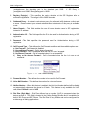
3.2.4 Phone Settings
The Phone Settings page configures the phone related operations. They are described in
details below.
Figure 1-25
Phone Settings
1. Title on LCD – The text entered here is shown on the LCD as a default message when
the phone is idle.
2. Auto Dial – This field enables the number entered on the LCD to be dialed out
automatically once the Auto-Dial Timeout expires.
3. Auto-dial Timeout – This field specifies the timeout duration (in second) for
automatically dialing out the number entered.
26
Web Configuration
EP-8201 User Manual
4.
Menu Configuration Password – This field specifies if a login ID / password is
required to access the Device CFG submenu in the Phone Menu.
5.
Voice Mail Indication – This field sets the LED on the top right hand corner to be
used to flash or illuminate when a Voice Mail is received.
6.
SMS Indication – This field sets the LED on the top right hand corner to be used to
flash or illuminate when a SMS message is received.
7.
Missed Call LED Indication – This field sets the LED on the top right hand corner to
be used to flash or illuminate when a miss call occurs.
8.
Keypad Lock – This parameter enables or disables the keypad lock feature. When it
is enabled, an unlock password is required to be entered. To activate keypad lock,
dial *99. To deactivate keypad lock, dial *99 and then enter the Unlock Password +
“OK”.
9.
Default Handsfree Device – This parameter defines whether the Speakerphone or
the Headset is for handsfree operation. Press the Speaker key to activate the
handsfree operation.
10. Function Keys Redefine – There are 5 function keys (R1 to R5) that are user
programmable.
Each key can be enabled or disabled individually and can be
redefined in two modes: Fixed and Manual.
In Fixed mode, five predefined functions are available for selection as shown below.
They are Phone Book, Do Not Disturb, Show Pending Call List, Call Forward, and
Speed Dial.
Figure 1-26
Programmable Keys – Predefined Functions
In Manual mode, each Speed Dial and DTMF Speed Dial
Figure 1-27
Programmable Keys 27
Web Configuration
EP-8201 User Manual
3.2.5 Save Changes
When all changes have been made, click on the Save Changes tab to save all settings to the
Flash memory.
Figure 1-28
Configurations Menu
The message window below is displayed when the saving is completed.
Figure 1-29
Popup Message for Configuration Saved
3.2.6 Discard Changes
Click on the Discard Changes tab to ignore all changes made.
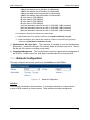
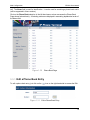
4.3 Phone Book
The EP-8201 has a built-in phone book with a maximum of 250 entries. Each entry contains a
Number field and a Name field. The maximum character for each field is 32 characters and
there is no restriction on the characters entered. The Number field is used to make the VoIP
28
Web Configuration
EP-8201 User Manual
call. The Name field is used for identification. It can be used for searching a phone book entrie
(will be supported in future version).
Click on the Phone Book selection in the left hand menu column accesses the Phone Book
Page shown below directly. All existing entries are displayed in ascending alphabetical order of
the Name field.
Figure 1-30
Phone Book Page
3.3.1 Edit a Phone Book Entry
To edit a phone book entry, just click on the
icon on the right hand side to access the Edit
.
Figure 1-31
Edit a Phone Book Entry
29
Web Configuration
EP-8201 User Manual
3.3.2 Delete a Phone Book Entry
To delete a phone book entry, just click on the
icon on the right hand side.
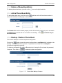
3.3.3 Add a Phone Book Entry
To add a phone book entry, just click on the
selection on the left hand menu column to
access the Add New Contact page as shown below.
Figure 1-32
Add a Phone Book Entry
The Number field must be entered properly in order for the dialing of this entry to be successful.
The Name field is optional and it is not used for actual dialing. Click
the Phone Book.
to add the entry to
3.3.4 Backup / Restore Phone Book
This function backups or restores the phone configuration.
Click on the
button to save the current configuration as config.dat which is placed on the
desktop. The Password field is optional. If a password is entered, the file config.dat is
encrypted and password protected.
To restore a configuration file, click on Browse button to locate the file and enter the password,
if required. Then click on
to restore the phone configuration.
Figure 1-33
Phone Book Backup / Restore
30
Web Configuration
EP-8201 User Manual
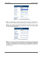
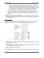
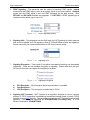
3.3.5 Auto Update
The Auto Update feature allows the phone book to be updated automatically and periodically via
a http / ftp / tftp server. Only xml file format is supported.
Click on the
selection in the left hand menu column to access the page below.
Figure 1-34
Phone Book Auto Update
Select
to activate this feature. Enter the Auto Update Schedule in the 24 hour format
HH:MM and the Auto Update File Name including the path as shown above. Once they are
completed, click on
to save the settings. When the schedule time is reached, the phone
will update the phone book with the file specified. If the specified file cannot be read
successfully, an error message is displayed on the LCD. Pressing any key will clear this
message.
Note: Please note that the amount of time required to perform the update depends on the number of
entries in the xml documents since it takes time to write the phone entries to the Flash memory. During
the Auto Update, the phone operation could be affected. It is recommended to set the Auto Update
schedule to a time when the phone is rarely used (say the middle of the night).
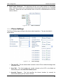
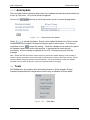
4.4 Tools
The Tools section is intended to offer the following functions: Online Upgrade, Change
Password, Backup/Restore Configurations, Reset Config, and Reboot as shown below.
Figure 1-35
Tools Menu
31
Web Configuration
3.4.1
EP-8201 User Manual
Tools
Click on the Online Upgrade tab to perform manual firmware upgrade. Enter the upgrade
address as shown below. Please contact your service provider to determine if there is a new
firmware available.
Figure 3-2
Upgrade
Firmware
WARNING: Once the upgrade starts, a message window is
displayed to show the upgrade status.
DO NOT TURN OFF THE POWER WHILE THE FIRMWARE
UPGRADE IS IN PROCESS!
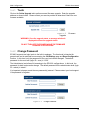
3.4.2
Change Password
EP-8201 supports two login levels to the built-in webpage. The User level is intended for
general user and is restricted from accessing the Call Settings page and Reset Configuration
function. In this level, only the password for the user level can be changed. The default
password for the user level (login ID = user) is “1234”.
The Administrator level allows full accessing to the EP-8201 configurations. In this level, the
password for both levels can be change. The default password for the administrator level (login
ID = admin) is “admin”.
It is important to keep a record the new password(s) entered. Please contact your local support
if the password is forgotten.
Figure 3-3
Change Password
32
Web Configuration
3.4.3
EP-8201 User Manual
Backup / Restore Configurations
This function backups or restores the phone configuration.
Click on the
button to save the current configuration as config.dat which is placed on the
desktop. The Password field is optional. If a password is entered, the file config.dat is
encrypted and password protected.
To restore a configuration file, click on Browse button to locate the file and enter the password,
if required. Then click on
to restore the phone configuration.
Figure 3-4
3.4.4
Configuration Backup / Restore
Reset Configuration
This function can only be accessed in administrator login level. Click on the Reset
Configuration tab to initiate the reset process. A message windows pops up to ask for
confirmation. Click “Yes” to reset all configurations back factory defaults. Click “No” to cancel.
Once the reset process is completed, the device reboots itself.
3.4.5
Reboot
Click on the Reboot tab to reboot the device. This will take couple minutes.
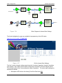
4.5 Gain Settings
This Gain Settings page is hidden and is only intended for advanced user who is technically
capable. The block diagram below shows the various gain stages in the phone.
33
Web Configuration
EP-8201 User Manual
Analog to
Digital
Converter
(ADC)
Microphone In
G1
Analog Front
End Gain
(AFE)
Speech Coder /
VAD /
Packetizer
G2
Encoder
Calibration
Gain
(CGC)
Digital Out
G3
Volume
Gain
(VGC)
Tone / FSK
Generator
Depacketizer /
Jitter Buffer /
Speech Decoder /
Comfort Noise
Generation
Analog to
Digital
Converter
(ADC)
Speaker
G6
Analog Front
End Gain
(AFE)
Figure 1-36
G5
Decoder
Calibration
Gain
(CGC)
Digital In
G4
Volume
Gain
(VGC)
Block Diagram for Internal Gain Settings
The blocks highlighted in green are available for programming in the URL below.
http://xxx.xxx.xxx.xxx//en_US/gain.html
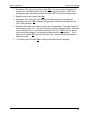
Figure 1-37
GUI for Internal Gain Settings
The first 3 rows in the gain settings page shows the 3 modes of operation: Handset, Handsfree,
and Headset. Each mode uses the same configuration as shown in the block diagram above.
The left hand column (first 3 rows) shows the mode of operation. The various gain settings are
described as follows:
1. Microphone AFE refers to the Analog Front End Gain block (G1).
34
Web Configuration
EP-8201 User Manual
2. Microphone VGC refers to the Volume Gain (G3). This gain should be changed with
caution since it affects the tone level as well. If the tone generated is a DTMF tone,
changing this gain may affect the detection of the DTMF tone by the outside network.
3. Speaker refers to the Volume Gain (G4).
4. Microphone CGC on the 4th row in the Gain Settings page refers to the Encoder
Calibration Gain CGC (G2). Changing this gain does not affect the signals from the
Tone / FSK generator.
5. Speaker Levels refer to the relative levels in the volume settings. There are a total of 6
volume settings from 1 to 6. The relative levels are listed in ascending order. When the
volume setting is set to 1, the Decoder Calibration Gain CGC (G5) is set to its preset
value (cannot be changed) + the relative level specified for volume setting 1. If the
relative level is blank, G5 is set to its minimum value. This means that the speaker is
effectively muted.
6.
The Analog Front End Gain (G6) is factory preset and cannot be changed.
35
Phone Menu
EP-8201 User Manual
4
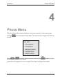
Phone Menu
The built-in Phone Menu allows configuration to the phone manually via the phone keypad.
Press the
the LCD:
key to activate the Phone Menu. There are five main categories as shown on
MAIN MENU:
1. CALL HISTORY
2. PHONE BOOK
3. MESSAGE CENTER
4. SYSTEM TOOLS
5. DEVICE CONFIG
Press
or
to scroll the menu selections and the press
the corresponding menu item number).
to select (or press
Please refer to the Appendix C for the complete Phone Menu for Multiple Server Mode.
36
Phone Menu
EP-8201 User Manual
4.1 Call History
The CALL HISTORY allows the user to view, edit or dial the caller information. For Single
Server Mode, the call history is organized with respect to each SIP Number programmed
(“Contact x”). For Multiple Server Mode, the call history is organized with respect to each profile
defined. Therefore, the user must first select the corresponding contact or profile desired first.
CALL HISTORY:
CALL HISTROY
1. CONTACT 1
1. PROFILE 1
2. CONTACT 2
2. PROFILE 2
3. CONTACT 3
3. PROFILE 3
4. CONTACT 4
4. PROFILE 4
Once this is done, the next menu is to choose the call history category (ANSWERED, MISSED,
DIALED) or to delete all call history.
CONTACT x:
PROFILE x:
1. ANSWERED CALLS
1. ANSWERED CALLS
2. MISSED CALLS
2. MISSED CALLS
3. DIALED CALLS
3. DIALED CALLS
4. DELETE ALL
4. DELETE ALL
The call entries of the selected category are then displayed. Press
or
to scroll
the call entries and then press
to select the highlighted entry. The following menu is
then displayed to prompt for further action to be performed on the selected entry. Select 1 to
dial the entry, 2 to save the entry to the phone book, 3 to delete the entry, and 4 to view more
detailed information of the entry.
XXXXXXX:
1. DIAL
2. SAVE
3. DELETE
4. DETAILS
37
Phone Menu
EP-8201 User Manual
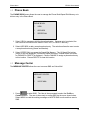
4.2 Phone Book
The PHONE BOOK menu allows the user to manage the Phone Book/Speed Dial Memory or to
dial an entry in the Phone Book.
PHONE BOOK:
1.
VIEW
2.
ADD NEW
3.
SPEED DIAL
1. Select VIEW to manage or dial the phone book entry. Once an entry is selected, the
user can then choose from the menu to DIAL, EDIT, or DELETE the entry.
2. Select ADD NEW to add a new phone book entry. The selection allows the user to enter
a new phone book entry (Name and Number).
3. Select SPEED DIAL to manage the Speed Dial Memory. The 10 Speed Dial entries
(empty or not) are displayed. Choose the Speed Dial entry / location and a new menu
for CHANGE or DELETE is displayed. Choose CHANGE to assign a phone book entry
to this location. Choose DELETE to clear this location.
4.3 Message Center
The MESSAGE CENTER allows the user to access SMS and Voice Mail.
MESSAGE CENTER:
1.
SMS
2.
VOICE MAIL
1. Press
to select SMS. The User is then prompted to select the Profile or
Contact desired. The user is then ready to access SMS via the menu shown below.
Select INBOX to read the existing messages or WRITE SMS to write and then send a
SMS.
38
Phone Menu
EP-8201 User Manual
SMS:
1.
INBOX
2.
WRITE SMS
2. Press
and then the Profile or Contact to access the Voice Mail directly.
Please note that the voice mail number must be predefined in the Call Settings Page for
the corresponding Profile or Contact.
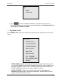
4.4 System Tools
The SYSTEM TOOLS menu has 9 selections for general phone management and information
viewing.
MAIN MENU:
1.
PHONE STATUS
2.
ONLINE UPGRADE
3.
SYSTEM VERSION
4.
RESET CONFIG
5.
RING TYPE
6.
RING VOLUME
7.
CALL FORWARD
8.
DEF. HANDFREE DEV.
9.
REBOOT
1.
PHONE STATUS – Select this to view the information assigned to the LAN port, PC
port, PHONE NUMBER, and HW INFO (hardware information). LAN port and PC port
information includes the current status, IP address, gateway address, and Netmask.
PHONE NUMBER includes the sip number assigned to each line.
2.
ONLINE UPGRADE – Select this to initiated online upgrade. User Name and
Password are required before entering the upgrade site. Please consult your local
support for the latest firmware version.
39
Phone Menu
EP-8201 User Manual
3.
SYSTEM VERSION – Select this to view the current version of both software and
hardware.
4.
RESET CONFIG – Select this to reset he phone to factory default settings. User
Name and Password are required.
5.
RING TYPE – Select this to assign the ring type of each line.
6.
RING VOLUME – Select this to set the ringing volume of all incoming calls.
7.
CALL FORWARD – Select this to programs the Call Forward settings for all lines.
8.
DEF. HANDFREE DEV. – Select this to set the default device (speakerphone or
headset) used for handsfree operation.
9.
REBOOT – Select this to reboot the phone. No confirmation is required.
4.5 Device Config
The DEVICE CONFIG menu configures the phone preference, network settings, and DHCP
service. User Name and Password are required in order to access this menu.
DEVICE CONFIG:
1.
PREFERENCE
2.
NETWORK CONFIG
3.
DHCP SERVICE
1.
PREFERENCE – Select this to configure the following settins: Language, Time Zone,
Date Time Server, and AUTO Configuration server.
2.
NETWORK CONFIG – Select this to configure the DNS, Gateway, PC port, LAN port,
and VLAN.
3.
DHCP SERVICE – Select this to enable or disable DHCP host service for the PC port.
40
Phone Operation
EP-8201 User Manual
5
Phone Operation
5.1 Making a Call
1. Pick up handset.
2. Dial a phone number.
3. Press
or wait for Auto Dial timeout (# key as well if enabled). Depending
on the configuration mode, the default Contact1 or Profile1 will be used to make
the call. (See notes below)
5.2 Making a Hands-Free Call
1. Press
.
2. Dial phone number.
3. Press
or wait for Auto Dial timeout (# key as well if enabled). Depending
on the configuration mode, the default Contact1 or Profile1 will be used to make
the call. (See notes below)
Notes:
a. Instead of pressing
, press one of the line keys (
,
) to select the Contact or Profile to be used for the call.
,
b. An alternative way to make a call is to press a line key (
,
,
) to select the appropriate line first before dialing a phone number.
, or
, or
41
Phone Operation
EP-8201 User Manual
5.3 Answering an Incoming Call
There are two ways to answer an incoming call:
1. Pick up the handset to answer the call normally.
2. Press the
button to answer in speakerphone mode.
5.4 Dialing from the Phonebook
1. Press
2. Choose PHONE BOOK (Press
)
3. Choose the Profile desired (for Multiple Server Mode only)
3. Choose VIEW (Press
)
4. Press
(UP) or
(Down) to view the Phone Book
5. Press
to select the highlighted entry
6. Select DIAL to dial out the number (Press
)
5.5 Viewing / Dialing from the Call History
1A. Press
to view the Missed Call List while on hook / idle
1B. Press
to view the Answered Call List while on hook / idle
1C. Press
to view the Dialed Call List while on hook / idle
2. Choose the Profile desired (for Multiple Server Mode only)
3. Press
or
to view the selected Call List
4. Press
to dial out the highlighted entry
5.6 Redialing the Last Number
1. Pick up handset
42
Phone Operation
2. Press
3. Press
EP-8201 User Manual
,
,
, or
to select a line
to dial out the last number dialed immediately
Or
1. Press
2. Press
or
select/high light the last number dialed from L1 to L4.
3. Press
to dial the number selected. The phone goes into Speakerphone
mode automatically and there is no need to select the line.
4. Pick up the handset to talk directly (Speakerphone mode turns off automatically).
5.7 Speed Dial
The Speed Dial function is available if one of the function keys (
,
,
,
, or
) is defined as Speed Dial. Press this Speed Dial key to
activate the Speed Dial Entries to be shown on the LCD. Select the desired entry and
then press
to dial it out.
5.8 Putting / Releasing a Call on Hold
To put a call on hold:
1. Press
button
To release a call on hold:
1. Press
button
5.9 Transferring a Call
To transfer a call to another extension:
1. Press
Transfer button
2. Dial phone number
43
Phone Operation
EP-8201 User Manual
3. Press
4A. Hang up for unattended transfer.
4B. Wait for the call to be answered and then hang up for attended transfer.
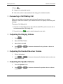
5.10 Answering a Call Waiting Call
When you are talking on the phone and another call comes in on your phone
extension, a short tone sounds in your handset and the LCD displays an incoming call
message.
To answer a Call Waiting Call:
1. Press the corresponding line key with an illuminated LED to put the current call on
hold and answer the Call Waiting Call.
2. Press the line key (
) again to switch between the two calls.
5.11 Adjusting the Ringing Volume
1.
Press
.
2.
Select SYSTEM TOOLS.
3.
Select RING VOLUME.
4.
Press
the LCD.
or
to increase or decrease the ring volume as shown on
5.12 Adjusting the Handset Receiver Volume
1.
Pick up the handset
2.
Press
or
shown on the LCD.
to increase or decrease the handset receiver volume as
5.13 Adjusting the Speaker Volume
1.
Press the Speaker button.
2.
Press
on the LCD.
or
to increase or decrease the speaker volume as shown
44
Phone Operation
EP-8201 User Manual
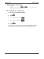
5.14 Adjusting the LCD Contrast
1.
While the phone is idle, press
or
LCD Contrast level as shown on the LCD.
to increase or decrease the
5.15 Resetting Phone Configuration
To reset the SIP Phone to factory configuration:
1.
Press
.
2.
Select SYSTEM TOOLS (Press
).
3.
Select RESET CONFIG (Press
).
4.
Press
5.
Enter the Username (default is admin) and Password (default is dbl#admin).
.
This will reset the entire phone configuration back to factory default settings.
45
Appendix A
EP-8201 User Manual
Appendix A: Dial Plan
Dial Plan defines how a number (VoIP) is processed when HT-812P receives it. This field is
located in the Calling Setting Window and it is available for both H.323 Phone and SIP Phone.
The Dial Plan is very flexible and can be configured for a wide range of dialing applications.
The basic syntax is “<event>:<action>|<event>:<action>|…”, where
<event> defines the event to be matched. A event consists of a sequence of digits. If a
specific digit has a limited range, use the syntax [A-B] where A and B are both digit (0 to 9)
and B is greater than A. The length of the input number can be limited by using “X” to
represent each unknown digit. If this field is omitted, it means any event.
<action> defines the action to be taken on the number received and it consists of “–“ (minus),
“+” (plus), and digits. “-“ followed by digits means to remove the digits from the beginning of
the number entered. “+” followed by digits means to add the digits in front of the number
entered.
“|” means or and the order of priority is from left to right.
Note: For practical use, it should not be possible to reach the maximum length of the Dial Plan
string.
Examples:
a. Dial Plan = “010:-010” means that the number dialed out will have the first 3 digits ”010”
removed when a number with the first digits as “010” is entered.
i. Number entered = “01082121234”, actual number dialed = “82121234”.
ii. Number entered = “82121234”, actual number dialed = “82121234”.
b.
Dial Plan = “1:+00” means that the number dialed out will have the “00” added in front of
the number entered when a number with the first digit as “1” is entered,.
i. Number entered = “1082121234”, actual number dialed = “00182121234”.
ii. Number entered = “82121234”, actual number dialed = “82121234”.
c.
Dial Plan = “001:-001+1751” means that the number dialed out will the first 3 digits “001”
changed to “1751” when a number with the first digits as “001” is entered.
i. Number entered = “00182121234”, actual number dialed = “175282121234”.
ii. Number entered = “82121234”, actual number dialed = “82121234”.
d.
Dial Plan = “XXXX:” means that the input number is limited to 4-digit long and will be
dialed out immediately when the fourth digit is entered.
e.
Dial Plan = “13XXXXXXXXX:+0” means that the input number is restricted to 11-digit
long and the first two digits must be “13”. When this condition is matched, the number
dialed out will have a leading “0” added.
i. Number entered = “13901234567”, actual number dialed = “013901234567”.
ii. Number entered = “12801234567”, actual number dialed = “12801234567”.
f.
Dial Plan = “13[6-9]XXXXXXXX:+0” means that the input number is restricted to 11-digit
46
Appendix A
EP-8201 User Manual
long and the first two digits must be “13” and the third digit can be 6, 7, 8,or 9. When this
condition is matched, the number dialed out will have a leading “0” added.
i. Number entered = “13901234567”, actual number dialed = “013971234567”.
ii. Number entered = “13001234567”, actual number dialed = “13001234567”.
Please note that the above samples are simple and intended to show the meaning of various
rules. They may not have any practical meaning. A combination of these rules (joined with the
symbol “|”) can be realized for a much more complicated dialing application.
47
Appendix B
EP-8201 User Manual
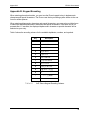
Appendix B: Keypad Encoding
When entering phone book entries, you must use the Phone keypad to key in alphanumeric
characters and special characters. The Phone uses the key encoding system similar to the one
found in cellular phones.
When entering alphanumeric characters and special characters, you press a key multiple times
to select the desired alphanumeric characters and special characters. If the same key is not
pressed after 1.5 seconds, the displayed alphanumeric character or special character will be
selected as your entry.
Table 2 shows the encoding scheme for the available alphabets, numbers, and symbols.
Key
Table B-1
Description
1
1
2
2abcABC
3
3drfDEF
4
4ghiGHI
5
5 Jj k l K L
6
6mnoMNO
7
7pqrsPQRS
8
8tuvTUV
9
9wxyzWXYZ
#
#@%&/~$[]{}
0
0
*
* . , ! ? : ; ( ) blank
VoIP Phone Keypad Encoding Scheme
48
Appendix C
EP-8201 User Manual
Appendix C: Phone Menu – Multiple Server Mode
49
Appendix C
EP-8201 User Manual
50
Appendix C
EP-8201 User Manual
51
Appendix C
EP-8201 User Manual
52