1
TCS 80X
User Manual
1
V3.0
JMK
31 October 1996
This equipment has been tested and found to comply with the following European Standards for
Electromagnetic Compatibility:
Emission Specification:
EN55013
(1990)
(Associated equipment)
Immunity Specification:
EN50082/1
(1992)
(RF Immunity, Fast Transients and ESD)
Mains Disturbance:
EN61000/3/2
(1995)
For continued compliance ensure that all input and output cables are wired with cable screen connected to Pin
1 of the XLR. The input XLR Pin 1 on BSS equipment is generally connected to chassis via a capacitor to
prevent ground loops whilst ensuring good EMC compatibility.
We have written this manual with the aim of helping installers, sound engineers and consultants alike get to
grips with the TCS-80X series and obtain its maximum capability.
If you are new to BSS equipment, we recommend that you begin at the start of the manual. If, however, you
are already familiar with the intended application, and just want to get the unit installed without delay, then
follow the highlighted sections.
Since this manual is dual purpose in covering both the TCS-803 and the TCS-804 units, information that applies
to only one of the units will be clearly noted for you. Where a particular function applies to both units, the
method of access and operation is identical for both units and the manual will show pictures of the TCS-804 as
an example.
Should you have any comments or questions about applying the TCS-80X series within your application, please
write to us, or e-mail us, at the addresses in the warranty section.
We welcome any comments or questions regarding the TCS-80X series or other BSS products, and you may
contact us at the address or World Wide Web site given in the warranty section.
2
Contents
Contents
1.0
The TCS-80X Series.
5
2.0
What is special about BSS Delays?
6
3.0
Earthing Requirements
7
4.0
Unpacking
7
5.0
Mechanical Installation
12
6.0
Mains Power Connection
13
7.0
Input Connections
14
7.1
8.0
8.1
9.0
10.0
10.1
10.2
10.3
11.0
11.1
11.2
11.3
11.4
11.5
11.6
11.7
11.8
XLR Plugs.
Output Connections
XLR Plugs
14
15
15
Control Connections
15
Powering Up
16
Default Settings and Display
Error Message Display
Mode Setting (TCS-804 only)
Parameter Selection
Bypass
Adjust Delay Time or Distance
Adjust Input and Output Level TCS-803
Adjust Input and Output Level TCS-804
Output Mutes
Program Store and Recall
Control Lockout
Utility
16
17
17
18
19
19
19
20
21
22
23
24
12.0
Master/Slave Operation
26
13.0
Linking (TCS-804 Only)
27
13.1
13.2
13.3
14.0
14.1
14.2
Stereo Pairs
Relative Delay, Mono mode
Relative Delay, Dual Chan Mode
Applications
Time Correction for Audience Distances
Time Correction for Speaker Driver
Placement
27
28
29
31
31
31
3
Contents
15.0
Midi Implementation
34
16.0
Chassis/0v Link Removal
36
17.0
BSS Temperature Probe
36
19.0
Extended Memory
37
19.0
Transient Suppressor Replacement 37
20.0
Option Transformers
38
21.0
Specifications
39
22.0
Warranty Information
41
Index
42
User Notes
43
Spare Parts Information
4
1.0
The TCS-80X Series.
The TCS-803 and TCS-804 form a series of multitap time correction units that
offer you the very best from todays' affordable digital technology. Utilising
advanced BSS proprietary conversion techniques they have exceptional
headroom, phase linearity and low level resolution that will not weaken a
conventional high quality analogue signal processing chain. Whether your
application is professional live sound, theatre sound, broadcast or disc
mastering the TCS-80X series will offer the most cost effective and intelligent
high specification multitap time delay that is available.
5
BSS Delays
2.0
What is special about BSS Delays?
Some of the features available within the series are:
• Stereo operation with two outputs per channel accurately linked, or dual
mono one-in/two-out.
• Mono one-in/four-out on the TCS-804. Mono one-in/three-out on the TCS803.
• Friendly rotary control knob for all parameter adjustments.
• Time or distance entry and display in milliseconds, feet, inches or metres.
• 10uS minimum delay steps.
• 105dB usable dynamic range includes full +20dBu headroom with fine
resolution at low signal levels. No companding or pre-emphasis means
superior high frequency performance.
• Exceptional phase linearity and HF accuracy from high sample rate and
gentle filtering.
• 12 non-volatile user programmable memories with remote recall via contact
closure or Midi.
• Maximum delay up to 2.6 seconds on TCS-804 in mono mode up to 1.3
seconds on TCS-803.
• Master/slave linking of multiple units by Midi.
• Delay time compensation for auditorium ambient temperature change. Fully
automatic on the TCS-804 with optional probe fitted.
• Electronic security lockout with optional mechanical security cover.
• Relay controlled signal bypass optionally available which is also linked into
fail-safe processor and power supply watchdog.
• Digital level control for both input headroom and output gain on the TCS804, gives automatic headroom compensation and allows remote control of
output levels and program storage.
Every TCS-80X is manufactured to the highest professional standards with a
robust steel case, high quality circuit boards and ICs, and high quality
components to provide reliable performance under the most demanding
conditions of the global sound-reinforcement environment. In common with
all other BSS equipment, the TCS-80X is subject to stringent quality control
procedures throughout the manufacturing process. Components are tested
against demanding acceptance criteria. Every completed unit is tested both
by measurement and in a listening test carried out by trained audio
professionals. To positively ensure reliability, all units are burnt-in for fifty
hours, before being tested.
6
Earthing Requirements
Unpacking
3.0
Earthing Requirements
WARNING! THIS APPLIANCE MUST BE EARTHED.
IMPORTANT: The wires in the mains lead are colour coded in accordance
with the following code.
Green and Yellow......Earth
Blue......Neutral
Brown......Live
As the colours of the wires in the mains lead may not correspond with
the markings identifying the terminals in your plug, proceed as
follows.
! The wire which is coloured Green and Yellow or Green must be connected
to the terminal which is marked with the letter ‘E’ or by the Earth signal
or which is coloured Green and Yellow or Green.
" The wire which is coloured Blue must be connected to the terminal labelled ‘N’ or coloured Black or Blue.
# The wire which is coloured Brown must be connected to the terminal
labelled ‘L’ or coloured Red or Brown.
Those units supplied to the North American market will have an integral
moulded 3 pin connector which is provided to satisfy required local standards.
The mains voltage selector switch provides a simple external adjustment to
allow operation on all international AC power standards. The allowable ranges
for the supply voltage are:
90VAC up to 132VAC on the 120V position and
180VAC up to 264VAC on the 240V position.
Outside of these ranges the unit will not work satisfactorily, if at all. Voltages
in excess of the maximum will probably cause damage. Voltages below the
minimum will cause the power supplies to drop out of regulation, degrading
the performance of the system.
4.0
Unpacking
As part of BSS' system of quality control, this product is carefully inspected
before packing to ensure flawless appearance.
After unpacking the unit, please inspect for any physical damage and retain
the shipping carton and ALL relevant packing materials for use should the unit
need returning.
In the event that damage has occurred, please notify your dealer
immediately, so that a written claim to cover the damages can be initiated.
See Section 22.
7
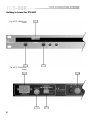
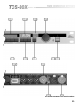
Getting to know the TCS-803
Fig 4.1 TCS-803 Front
Panel
Fig 4.2 TCS-803 Rear
Panel
8
All numbers in bubbles refer to Section numbers.
9
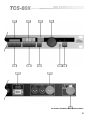
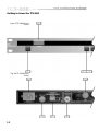
Getting to know the TCS-804
Fig 4.3 TCS-804 Front
Panel
Fig 4.4 TCS-804 Rear
Panel
10
All numbers in bubbles refer to Section numbers.
11
Installation
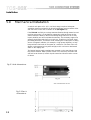
5.0
Mechanical Installation
A vertical rack space of 1U (1¾" / 10½mm) deep is required. Adequate
ventilation must be provided for by allowing sufficient room around the sides
and rear of the unit for the circulation of air (See Figure 5.1).
If the TCS-80X are likely to undergo extreme vibration through extensive road
trucking and touring, it is advisable to support the unit(s) at the rear and/or
sides to lessen the stress on the front mounting flange. Failure to do so may
impair reliability and will invalidate the warranty. The necessary support can
generally be bought ready-built, as a rack tray. As with any low-level signal
processing electronics, it is best to avoid mounting the unit(s) next to a strong
source of magnetic radiation, (for example, a high power amplifier), to help
keep residual noise levels in the system to a minimum. The front of the unit
should not be exposed to long term sunlight, as this can have a detrimental
effect on the display lens.
The internal power supply regulators are mounted on the case sides and use
this as their heatsink. After a period of time in an enclosure, the metal case
will feel hot to the touch, but this is quite normal and should not be a cause
for alarm.
Fig 5.1 Unit dimensions.
Fig 5.2 Rack
dimensions.
12
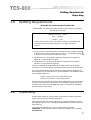
Connecting to Power
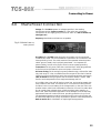
6.0
Mains Power Connection
Voltage: The TCS-80X operate on voltages specifies in the earthing
requirements section (Refer to section 3). If the unit(s) are accidentally
connected to an AC supply giving in excess of 132V AC, refer to section 19,
(See Figure 6.1).
Frequency: Both 60Hz and 50Hz are acceptable.
Fig 6.1 Mains fuse on
rear panel.
Grounding: The TCS-80X must always be connected to a 3-wire grounded
('earthed') AC outlet. The rack framework is assumed to be connected to the
same grounding circuit. The unit(s) must NOT be operated unless the power
cables' ground ('earth') wire is properly terminated - it is important for
personal safety, as well as for proper control over the system grounding.
Connections: The AC power cable has a moulded 3-pin utility plug attached
to the free end to facilitate the correct and proper connections.
AC Power Fusing: The incoming line power passes through a 150mA (for 240V
only) anti-surge ('T') fuse, accessible from the rear panel (The fuse is rated at
250mA for 120V and 150mA for 240V). If the fuse blows without good reason,
refer to section 19. Always replace with an identical 20mm x 5mm T rated
fuse for continued protection from equipment damage and fire.
It is unlikely that a fuse will fail during normal use, and must be treated with
some caution to the cause, if it should do so. One of the most likely reasons
for failure is the incorrect setting of the voltage switch on the rear of the unit.
Another reason could be the inadvertent connection of line to line rather than
line to neutral phase voltages when using three phase power supplies. In
either case, internal transient suppressor can be damaged, and consequently
replacement fuses will continue to blow, providing protection for your unit.
The damaged suppressors must be removed from the unit to allow further use,
and should be replaced as quickly as possible to provide continued protection.
Refer to section 16 for information on replacing these suppressors.
13
Input Connections
7.0
Input Connections
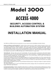
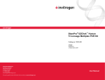
7.1 XLR Plugs.
The input signals are 10k ohm active balanced on a standard 3 pin 'female'
XLR which will accept levels up to +20dBv, and can drive into loads of
600ohms or greater. The wiring convention is as follows: (See Figure 7.1):
Pin 1: No connection (the shield of the drain wire can be terminated
here if desired).
Pin 2: Signal '+', in phase or 'HOT'.
Pin 3: Signal '-', out of phase or 'COLD'.
For unbalanced sources (See figure 7.1):
Pin 1: Leave open, or link to pin 2.
Pin 2: Shield, braid, or screen wire.
Pin 3: Signal '+' or 'HOT' (inner core).
There is no internal ground connection to Pin 1 of the female XLR to avoid
possible interconnection earth loops. The input signal cable shield must
therefore be tied to ground, or signal 0V, at the source end.
Fig 7.1 XLR Plug Wiring
If the equipment driving the TCS-80X has only unbalanced outputs then you
will need to add a wire jumper such that the screen connection on Pin 1 of the
XLR is shorted to either Pin 2 or Pin 3, depending on system convention.
If the equipment being connected to the TCS-80X outputs have only
unbalanced inputs, then we recommend that you still use a balanced (i.e. 2
core shielded) cable. You should ground the shield from the pin 1 connection,
whilst the cold connection should be used as the 0v ground and the hot
connection for the live, on the unbalanced input. The cable screen should not
be connected through to the chassis/0V. Strict adherence to this will help to
eliminate potential ground loop hums.
Strict adherence to the wiring conventions noted above within a fully
balanced signal system will yield the best possible results with none of the
problems normally associated with interconnected audio equipment.
Wherever possible, cable screens should not be connected to any signal pin,
but rather left to perform a cable shielding function only.
Under no circumstances should the safety ground wire be removed from the
mains AC power connector as an interim measure to achieve similar results.
Please refer to section 16 for information on this procedure.
14
Output Connections
Control Connections
8.0
Output Connections
8.1 XLR Plugs
The four signal outputs are DC blocked low impedance unbalanced from a
standard 3 pin male XLR and are designed to drive up to +20dBv into 600
ohms or greater. The wiring convention is as follows:
Pin 1: Connects to shield, screen or drain wire.
Pin 2: '+', hot or 'in phase' output.
Pin 3: '-', cold or 'out of phase' output.
If the amplifiers you are feeding have unbalanced (single ended) inputs, but
are fed from standard pin to pin XLR cables (See above), simply link the cable
at the crossover end as follows:
Pin 1: Connects to shield or screen wire.
Pin 2: Link to Pin 1.
Pin 3: Connects to the inner 'hot' or live core.
Unbalanced transmission is not recommended for connections to distant
equipment, but is generally acceptable for local connections within the rack,
or to an adjacent rack.
Technicians note: As with a traditional transformer balanced output, either
output phase (+ or -, hot or cold) can be linked to ground to 'unbalance the
line' without upsetting the operation of the unit. BSS follows the convention of
'screen goes forward with the signal'. As with a transformer, output level
remains the same in the unbalanced mode.
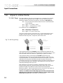
9.0
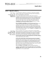
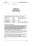
Control Connections
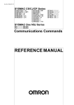
Both the TCS-803 and TCS-804 have two external control ports, one being the
Remote Program Selection, the other a standard MIDI control interface having
both IN, THRU and OUT connectors. More about the MIDI option and its
control codes are detailed in section 15. The 9 pin Remote Program Selection
'D' type connector is wired as a 4 by 3 matrix which allows by simple switch
closure, the selection of 12 user programmable memories. Figure 9.1 gives the
matrix pinning for each program number.
Remote Program The voltage available at these pins is less than 5V and current limited, so that
Selection no particular attention needs to be paid to safety and either momentary or
latching switch closure is all that is required to recall a memory number.
Individual screened cable is not required to connect your remote switching
box to the TCS-80X, however it is recommended that you use a cable that has
an overall screen, which should be connected to your control box at one end
and the designated pin on the D-Connector at the other end.
PX is the program number which is recalled by connecting together the two
designated pin numbers. Pins 5 and 9 are connected to ground
Fig 9.1 Remote Program
Selection D-Connector
Wiring
15
Powering Up
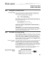
10.0
Powering Up
When the TCS-80X is switched on, by operating the power on-off switch
located on the rear panel, the internal circuitry carries out a series of routine
diagnostic tests. The display will show a series of numbers which will advise:
• The TCS model number, plus a suffix ‘E’ if the internal memory has been
extended.
• The software version number currently fitted.
• Which interface option is fitted (TCS-804 only).
• If the BSS temperature probe is fitted (TCS-804 only)
10.1 Default
Settings and
Display
Following the startup routine and screen display, the TCS-80X will
automatically resume the settings that were last selected, and show the last
selected delay before the previous switch-off. When first powered up, the
factory set defaults will be as shown below.
The internal memory automatically remembers all switch functions and
display readings when the unit is switched off, so it is not necessary to reload
level and delay information every time the unit is activated. The same applies
for the user programs, whose memory retains their contents indefinitely when
mains power is removed.
Factory Default Settings:
16
TEMP
20°C
HEADROOM
+10dBu
GAIN
0dB
DELAY
0mS
MIDI CHN
CH.1
Tx. MODE
Tr. Pr
PGM MEMORY
P1
MODE
MONO
LINKING
None
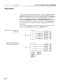
10.2 Error Message
Display
Should the unit detect bad data internally, on a control interface, or an
incompatible mode setting, an error message number will be displayed to
show there is a problem. Any other indicated errors will require the unit to be
referred to an authorised service centre for repair.
Err.3 Midi timing error
Err.4 Option interface timing error
Err.5 Incorrect mode selected for master-slave linking or program recall
Err.6 Program Store Error
10.3 Mode Setting
(TCS-804 only)
The two modes of operation of the unit are selected by the push switch
located on the rear panel and labelled ‘mode select’.
Confirmation of the selected mode will be seen from the front panel display.
For MONO mode the top headroom meter display will be active, as will the
legend MONO. In DUAL CHANNEL mode the MONO legend will be
extinguished and replaced by the letters L and R adjacent to each headroom
display meter.
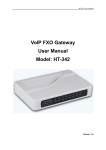
The MONO operation mode is where all four delay outputs are part of the one
channel, this being the ‘left’ channel. Four independent delay taps from the
one unit give extra flexibility in system design. Please use the legend printed
above the delay selection switches.
In DUAL CHANNEL mode, the TCS-804 is partitioned, to give two identical
channels, each one having two delay outputs. Each channel can be operated
separately, or with the output pairs linked as is necessary for true stereo
operation. Linking is explained fully later on in this manual.
Fig 10.1 Mono Mode
Grouping
Figure 10.2 Stereo
Mode Grouping
17
Parameter Selection
11.0 Parameter Selection
This section deals with selection of the various modes of operation as well as
the adjustment of delay times and signal path gain structure.
Where a feature is common to both the TCS-803 and TCS-804, the selection
and adjustment is identical. Where there is a difference, it will be described
separately.
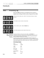
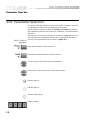
Fig 11.1 Key to
diagrams
We hope you will find it quite intuitive to operate and suggest that you have
your unit with you to operate the switches as you read through this section.
The key to the diagrams that follow is shown in Figure 11.1:
Press specified button to select function X.
Press and hold specified button to select function X.
Turn the rotary control knob to adjust the parameter.
Push and turn rotary control knob to adjust the parameter.
Indicator light off.
Indicator light on.
Indicator light flashing.
Display reading.
18
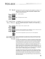
11.1 Bypass
The bypass function or IN/OUT provides a switch toggle for cancellation of all
delay times. For complete cancellation of all electronic stages and level
settings, the output relay option needs to be specified. The bypass is then a
complete input/output wired link.
IN:
Normal operation.
Out: Total bypass input to output.
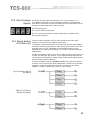
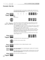
11.2 Adjust Delay
Time or Distance
The TCS-80X will allow the required delay to be set in ‘time’ or in ‘distance’
units. This is selected by operating the units switch. If more delay time is
required, an extended memory option is available which is easily installed. To
set the delay:
Select a delay to read or adjust it’s value.
If required, select to alter display units. Readings in excess of '9999' will show
‘FEET’ and then automatically change to read feet.
Turn knob for fine adjustment or push and turn for coarse adjustment.
11.3 Adjust Input
and Output Level
TCS-803
Separate input headroom and output level controls are provided on the front
panel to enable optimum operating headroom setting, and individual output
level trim.
The input control range allows for a maximum operating level between 0dBu
and +20dBu. The output level control allows for individual gain adjustment of
the three outputs by plus or minus 10dB. There will be unity gain through the
unit when both input and output level controls are in their central position.
It is most important for correct operation of the unit that you set the input
level control correctly. As is common for all electronic equipment, care must
be taken to ensure that the input signal does not exceed the maximum
internal clipping level and the input headroom meter is therefore an important
display. When setting up, ensure that on one hand your maximum signal peak
does not exceed the 0dB scale point, and on the other that it is not wasteful of
dynamic range. It is always adjusted first on initial setting up.
The output level trims will be useful for providing some degree of individual
adjustment for each of the three outputs. They can be adjusted following the
correct setting of input headroom. Remember that if the input control needs to
be turned back, the output control will need to be turned up to restore the
through gain as these two controls work together. The input control works to
maximise operating dynamic range whilst the output control works to trim the
required through gain.
19
Parameter Selection
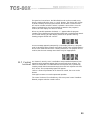
11.4 Adjust Input
and Output Level
TCS-804
Input headroom and output level adjustment is essential for the correct
operation of the unit to maximise dynamic range and trim individual output
gains. The section for TCS-803 should be read if more detail is required, but
remember that for the TCS-804 all adjustment is performed digitally, rather
than with analogue control knobs. To enter the level adjustment mode:
The '|-' symbol in the display denotes tandem adjustment
L denotes left channel adjustment
r denotes right channel adjustment
The display is showing the level in dBu for input clip (0dB on the headroom
meter). The symbol to the left is indicating which of the two input channels is
selected for adjustment. The ‘|-’ symbol is showing that both channels are
being adjusted together.
To Adjust Input Levels
Turn knob to set headroom value in dBu.
Press again to select next channel or step through to exit.
For speed and convenience of use, the sequence that is used to cycle through
is different depending on whether MONO, DUAL or STEREO mode has been
selected:
20
MONO:
Headroom;
TWO CHN:
L;
r;
|-; out.
STEREO LINK: |-;
L;
r; out.
out.
To Adjust Output
Levels
At any time when in the LEVEL mode, a delay button can be selected to
allow trimming of output gain. The adjacent LED will stop flashing and
remain on, to indicate selection. The display will change to show the input to
output through gain, in dB, for the output selected.
Turn the knob to set the gain required in dB
One of the many advantages of this digital level control is seen when
adjusting input headroom. The input to output through gain will always be
held constant at the dB value previously set because internal circuitry
automatically provides the necessary correction to output level. This will be
limited to a range such that the sum of input headroom in dB plus the through
gain in dB is within a range greater than -10dB and less than +20dB and
ensures that the output circuitry can not be set to clip the signal.
WHEN INITIALLY SETTING UP THE UNIT, BE SURE TO SET ALL OUTPUT
GAINS TO 0dB. PROCEED TO SET INPUT HEADROOM, AND FINALLY
TRIM EACH OUTPUT GAIN TO SUIT. FAILURE TO FOLLOW THIS ROUTINE
MIGHT CAUSE THE AUTOMATIC THROUGH GAIN COMPENSATING
CIRCUITRY TO RUN OUT OF RANGE.
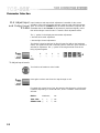
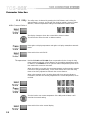
11.5 Output
Mutes
The TCS-804 will also allow independent muting each of the four delay
outputs.
Enter the ‘LEVEL’ mode:
And select the delay output to mute.
Press in control knob.
Press and turn.
21
Parameter Selection
The output selected will now be muted. On releasing the control knob and
returning to level display, the mute mode will be indicated by “pause” lines
to the left hand side of the display.
Press and turn.
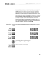
11.6 Program
Store and Recall
There are 12 program memories available for storing different front panel
settings. These programs are accessible either from the front panel or via
either of the rear panel control interfaces.
For the TCS-803 each program can store the individual delay times or distance
that has been set for the three outputs. Level information is not stored as it is
adjusted by the front panel analogue controls.
For the TCS-804, both delay time and output gain information are stored,
together with information on mode select, stereo linking and relative delay.
Input headroom is not stored, as this would be dangerous when recalling
programs with widely different settings.
The Program, Store and Recall operations are similar for both units, and to
enter the program mode:
The display shows the current program number.
Turn knob to select program number.
Sets parameters to those of displayed program number.
Stores current parameters into displayed program number and will overwrite
any previous settings.
Once either Recall or Store has been pressed, the display returns to the delay
display that was shown before the Program mode was selected. Press at any
time to exit Program mode.
Press at any time to exit Program mode.
22
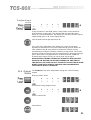
For speed and convenience, the PROGRAM mode can be accessed at any
time by pressing either the ‘store’ or ‘recall’ buttons. The display will change
to show a flashing current program number, but the store or recall function
will not be activated unless the switch is pressed a second time. Once the
button is pressed twice, the current settings are stored or the program is
recalled, and the display will return to normal.
When any storable parameter is altered, a ‘.’ appears after the program
number to show that the program has been edited and not subsequently stored.
It will remain blinking for other display modes as an operator warning.
Pressing program STORE will cancel it.
An error message appearing temporarily on the display following a program
recall is advising that the program was initially stored in the opposite MONO/
DUAL CHN mode than the unit is currently switched to. The program will be
recalled, but the error message warns that it may be inappropriate:
11.7 Control
Lockout
An ‘electronic security cover’ is available to stop unauthorised persons from
tampering with parameter settings that have previously been entered. The
switch to activate this is located behind the front panel and is operated by
inserting a small blunt instrument through the round hole adjacent to the IN/
OUT switch. The corresponding legend will appear.
'Safe On' allows all parameters to be viewed as normal, but none can be
altered.
Press again to return to normal unprotected operation.
The control lockout will not disable any of the rear panel control interfaces.
External program selection remains active.
23
Parameter Selection
11.8 Utility
MIDI Channel Select
The utility menu is selected by pressing the UNITS button and holding for
approximately 2 seconds. Access will then be given toMIDI channel number
selection, ambient temperature setting and master/slave transmit mode.
The display changes to show the current MIDI channel number.
Turn the knob to select channel or address number;
Press again to display temperature and again to display master/slave transmit
mode.
Press and hold to exit UTILITY.
Temperature Both the TCS-803 and TCS-804 allow compensation for the change in delay
times needed to maintain a fixed distance as the ambient temperature varies.
In addition, the TCS-804 has as an optional external temperature probe which
then makes this correction automatic.
When the probe is not used, the current temperature can be manually entered.
If this then changes substantially, a new value entered will cause the delay
times to be slowly adjusted to maintain the correct distance.
When using program recall, the delay times which are stored as distance
information, will also be correctly adjusted for the current temperature, when
recalled.
Turn the knob to set current temperature. If the BSS probe is fitted, it will
override the manual setting.
Press and hold to exit to normal display.
24
The control knob increments in one degree steps and the range of temperature
adjustment available extends from -19°C to +44°C. If there are a number of
TCS-80X units within an installation, then rather than have a temperature
probe fitted to each, it is possible to transfer the temperature data from one
master probe to all other units by utilising the MIDI interface. Please refer to
section 12 for an explanation of how to implement this feature.
Please note that when a probe is first plugged in, it can take up to one minute
before the temperature appears on the display. Allow at least ten minutes for
the probe temperature to stabilise before setting delay times and if the probe
is unplugged at any time, the last measured temperature remains active.
The probe should be placed in a position away from equipment heat, out of
direct sunlight and where a typical temperature for the venue is likely to be
found. A standard screened XLR lead may be used to connect the temperature
probe to the jack adapter which plugs into the TCS-804.
Master/Slave Transmit When setting up for master/slave operation it is possible to select a number of
mode different modes and these are selected from the utility menu.
Turn the knob to select the required mode from:
tr. -;
tr.t°;
tr.SL;
tr.Pr
Press and hold to exit to normal display.
25
Master/Slave Operation
12.0
Master/Slave Operation
By using the MIDI control interface it is possible to interconnect a number of
TCS-803 and TCS-804 units so that one unit takes on a MASTER function while
other selected ones assume a SLAVE function. In addition there are three
different modes of operation to choose from determining what data is to be
transferred. Select this from within the UTILITY menu at the same time as
setting MIDI channel number. Refer to section 10.
Using standard MIDI DIN connecting leads, link the MIDI OUT socket of the
unit you wish to be MASTER to the MIDI IN socket of the first SLAVE unit.
Continue in a ‘daisy chain’ fashion linking MIDI THRU to MIDI IN on all the
other units that are to be controlled. (The MIDI out socket is only used on the
MASTER unit).
Be sure to set equal MIDI CHANNEL numbers for all units, and set the
required transmit mode on the MASTER.
When a master unit is first powered up, after a few seconds it will transmit all
selected parameters to the slaves. If there is any doubt as to whether the slave
units are ready to receive the initial data, check that the slaves are NOT
powered up after the master, or that cabling is done after the master is turned
on. A second initial dump of data can be sent by altering the transmit mode
on the master and then returning it back to that required. Thereafter
parameters are only transmitted from the master when they are altered.
Transmit mode ‘tr t°’. This mode is for transferring temperature data only, between Master and
Temperature Linking Slave. It suppresses all data except temperature on the MIDI interface and
therefore allows a BSS temperature probe connected into the master to act for
all other interconnected units. Where temperature compensation is desirable,
this will avoid having to install a BSS probe for each unit in the system.
Transmit mode ‘tr.Pr’. A change in this mode measns only program recall and temperature data are
Transmit Program transferred. When you Recall a program on the master, all other
interconnected units will respond by recalling their own program with the
same number. If the display is set to Program number on the slave units,
confirmation of program change will be shown.
Temperature data is also transferred so that the stored distance information
from the slave units' programs will allow temperature compensated delay
times to be shown.
Transmit mode ‘tr.SL’. This is a full Master/Slave linking mode where all delay settings, in/out status,
Transmit Slave and temperature data is transmitted by the Master unit for duplication on each
slave unit. Program recall and level information is not transmitted and remains
locally adjustable.
For this mode you can only mix TCS-803 and TCS-804 units within a system if
the latter is set to its mono mode, and similarly all TCS-804 units within the
same system must be set to the same mono/dual channel mode. The error
message ‘Err.5’ will be displayed if this is not the case.
Transmit mode ‘tr. -’. Selecting this mode allows MIDI transmit to be switched off, whilst still
Transmit Off allowing MIDI receive to be functional. It is of use mainly in large MIDI
control setups and controls data to the MIDI OUT socket only.
26
Linking (804 Only)
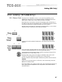
13.0 Linking (TCS-804 Only)
13.1 Stereo Pairs
Selecting DUAL CHANNEL mode in a unit gives the possiblility to link
together the delay times on each left/right group to facilitate maintaining a
stable stereo image as the overall delay time offset is adjusted.
Note that Delay 1 and Delay 2 form the first left/right group, whilst Delay 3
and Delay 4 form the second left/right group. The following example uses the
first group numbering but it applies equally to the second group.
Set both delay 1 and delay 2 individually to minimum delay, or set an initial
imbalance if this is required in your particular situation.
Pressing both switches SIMULTANEOUSLY cause them to become linked
together:
One of the delay indicator lights will now be flashing to show that this group
is linked, and that adjustment of one will drag the other with it.
Turn the knob to set the required delay, and the incremental change will be
applied EQUALLY to both delay 1 and 2.
Selecting either delay switch will display it’s absolute value, which will
include any initial offset that was entered prior to being linked.
When the switches are pressed again simultaneously, both units will become
unlinked.
LINKS may only be switched on or off when in the normal delay mode and
not when in Relative mode.
Note that LINKING only applies to delay time. The individual through gain for
each output remains independent and is adjustable by the LEVEL mode as
described earlier.
27
Linking (804 Only)
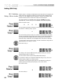
13.2 Relative
Delay, Mono mode
Relative delay is a display and adjustment mode that allows the assigning of
either of the four outputs as a reference such that all other outputs will be
linked to it, and dragged when the reference is moved. The relative delay
between reference and a chosen other output is also displayed.
This unique facility is invaluable when using the TCS-804 as an array
alignment tool, or when using it for loudspeaker driver offset alignment.
Enter the relative mode:
The four flashing red LEDs indicate to choose which delay is to be assigned as
the reference. Selecting delay 3 gives:
The red indicator points to delay 3 to confirm it is the reference, the green
indicator underneath shows that this is the delay currently being displayed,
and the three remaining green indicators are flashing to warn that their
respective delay outputs will all be dragged when delay three is adjusted.
Turn the knob to set the required delay, and the incremental change will be
applied EQUALLY to delay 1, 2 and 4.
Now select delay 1:
The display will show the RELATIVE delay between delay one and the
reference delay (which is delay 3).
Turn the knob to set the required delay RELATIVE to delay 3
It is possible to display and adjust the RELATIVE delay for any of the non
reference delay outputs in a similar manner.
Confirmation of the absolute delay time can be obtained by exiting the
relative mode and selecting delay display in the usual manner.
Exit relative mode:
and select delay 1:
28
In the relative display mode both positive and negative delays are indicated
to show the true displacement. It is quite likely that you will want to select
the units to display and adjust in distance, rather than time, so that the setting
up is much more intuitive to what you are measuring.
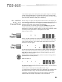
13.3 Relative
Delay, Dual
Channel Mode
Relative delay is a display and adjustment mode that allows the assigning of
certain outputs as references, such that the other outputs of the pair are linked
to it, and dragged with it when it is adjusted. The relative delay between
reference and the other chosen output is also displayed.
This unique facility is invaluable when using the TCS-804, and in the dual
channel mode there are two possible applications for relative linking
depending on whether the system is stereo, or a split band loudspeaker system
correcting for array displacement or loudspeaker driver offset.
Enter the relative mode:
Delay 1 red LED confirms that it is the reference for one group, and delay 2
and 3 red LEDs flash to indicate selection of the other reference, depending
on the chosen application. For a stereo system select delay 3 as the other
reference for the other group:
The two red indicators point to the reference outputs, amd the green LED for
delay 3 shows that this is the delay currently being displayed. The flashing
green LED for delay 4 is indicating that it is linked to delay 3 and will be
dragged by it, when adjusted.
Turn the knob to set the required delay, and the incremental change will be
applied EQUALLY to delay 3 and 4.
Now select delay 4:
The display will show the RELATIVE delay between delay 4 and the reference
delay which is delay 3.
Turn the knob to set the required delay RELATIVE to delay 3.
In a similar manner, the absolute value can be displayed and adjusted for the
other reference output, delay 1 and its associated linked output, delay 2.
Confirmation of the absolute delay time can be obtained by exiting the
relative mode and selecting delay display in the usual manner.
29
Linking (804 Only)
Exit relative mode:
and select delay 4:
If the other reference output has been chosen as delay 2, rather than delay 3,
then the above description of operation is still identical but with delay outputs
1 and 2 as reference pulling delays 3 and 4 with them. The indicators will
confirm this action.
Stereo links are also active in relative mode and may cause additional delays
to be dragged by the reference.
In the relative display mode both positive and negative delays are indicated
to show true displacement. It is quite likely that you will want to select the
units to display and adjust in distance, rather than time, so that the setting up
is much more intuitive to what is being measuring.
Although seemingly complex in description, the relative mode is simple to
use after a short time. Remember: The red LED shows the reference delay, and
a flashing green LED shows a linked delay which will also be dragged when
it’s reference is moved.
30
Applications
14.0 Applications
14.1 Time
Correction for
Audience
Distances
In any large public auditorium it is necessary to arrange the loudspeaker
system in clusters which are distributed around the arena to help obtain a
more uniform distribution of sound level.
For any given position within the arena a listener will be hearing a
combination of both the direct sound from the stage, and that from the nearest
distributed cluster. Because the speed of sound in air is considerably slower
than that of the equivalent electrical signal in the cable, the audible sound
from the nearest cluster will be heard by the listener slightly before that
arriving from the stage. The time delay between these two needs to be
compensated for, otherwise the listener will hear anything from a slightly
unintelligible sound to one that is totally indistinct.
Both the TCS-803 and TCS-804 can be used to cure this situation by
connecting one of its delay outputs to the distributed cluster. The delay time
needed will be equivalent to the distance between the loudspeakers.
Remember that the speed of sound at 20°C is approximately 343 meters per
second. This gives you a rule of thumb of 1 msec/ft, or 3 msec/metre. When
using multiple ‘delay’ clusters or when working in stereo, it will be up to the
user to decide whether it is better to use the TCS-803 or the TCS-804 switched
to mono or dual channel mode.
14.2 Time
Correction for
Speaker Driver
Placement
When a loudspeaker sound system is constructed which utilises different
loudspeaker drivers for separate frequency bands it is not generally possible to
mechanically mount them all such that each sound source is in the same
vertical plane. The effect of this is that phase errors might occur between
drivers which produce a substantial cancellation of the signal around the
crossover region, and there can also be a general lack of transient clarity to
the sound resulting from a poor impulse response due to inaccurate combining
of the wavefront arriving at the listener.
It is the vertical displacement of the loudspeakers versus the wavelength of
the signal around the crossover region that causes the phase cancellation.
Remember that the wavelength of a 1kHz sinewave is 23cm and for a 5kHz
signal it is 7cm. For zero cancellation the vertical displacement must be in
whole multiples of the wavelength. For a good impulse response the zero
phase start point for each loudspeaker drive unit must be in the same vertical
plane. Both of these criteria will probably therefore require each MF and HF
drive unit to be time delayed from the LF drive unit.
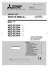
Both the TCS-803 and the TCS-804 are ideally suited for this style of
correction. However because you need to delay after the main loudspeaker
crossover, a separate delay channel is needed for each ‘way’ of the crossover
(See Figure 14.1). This can be very wasteful of facilities and not economic for
a typical three or four way stereo system.
31
Applications
A very powerful method utilising delays with a multiple loudspeaker system is
to integrate the delay into the crossover such that one multitap delay will
provide all the facilities for one channel of a sound system. The BSS FDS-360
Electronic Crossover has built into it a special interface which will allow
interconnect of either the TCS-803 or the TCS-804 (See Figure 17.2). For
example, two TCS-803 units will then provide all the time correction needed
to correctly align a full four way stereo sound system; a single TCS-804 unit
will provide all the time correction needed to correctly align a stereo three
way system.
A special interface connector is available to assist in the connection of the
delay unit to the FDS-360 rear barrier strip (See Figure 14.3).
Fig 14.1 One Delay per
Channel
Fig 14.2 FDS-360 and
TCS-80X Integration
32
Fig 14.3 FDS-360 to
TCS-80X Wiring
33
Midi Implementation
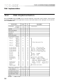
15.0
Midi Implementation
Both the TCS-803 and the TCS-804 can be controlled externally via the MIDI control interface. All the relevant
parameters are accessible where applicable. However, both input headroom and output gain are not available
for the TCS-803 model.
NOTES
34
X=No O=Yes
Midi Implementation
Chassis/0v Link Removal
Receive Notes:
The Delay LSB must precede the MSB. If Delay LSB is not received then it is
assumed to be 0. Increment may be used to obtain resolution down to 10us.
The Stereo mode flag checks for the correct setting of the mono/stereo switch
and produces an error message if there is a conflict.
Transmit Notes:
Delay times are transmitted as LSB then MSB then INCrement.
General Notes:
Delay times are transmitted and received correctly for 20°C. If the
temperature value set on the unit is different to this, then values will
automatically be adjusted.
16.0
Chassis/0v Link Removal
For both TCS-80X units the signal 0v ground is connected to the metal chassis,
which in turn is connected to the safety ground. In the unlikely event that the
link needs to be removed, or if a small amount of impedance needs to be
added to reduce earth loop currents, then proceed as follows:
Since both the audio inputs and outputs are wired fully balanced, we suggest
that you fully check that all audio wiring is correct prior to proceeding.
CAUTION: Under NO CIRCUMSTANCES should the incoming ground wire
be disconnected from the power line cord or from the internal chassis
connection as an alternative to this procedure.
• Disconnect the mains power cord and remove the top cover from the unit.
• Locate the green wire bolted to the chassis immediately above the 9-pin 'D'
connector which terminates onto the PCB at a point marked 'AGND' (See
Figure 16.1).
• Remove the end of this wire link from the chassis connection, fold over and
FULLY INSULATE.
• The signal 0v (AGND) is now separate form the chassis.
The other green wire terminated onto this chassis bolt connects the output XLR
pin 1 connections to the chassis. Under NO CIRCUMSTANCES is it
recommended that this link is removed.
35
BSS Temperature Probe
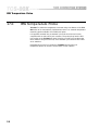
17.0
BSS Temperature Probe
TCS-804: To enable the temperature corrected delay time feature of the TCS80X series to be automatically implemented, there is an external temperature
measuring probe available as an additional option.
It is supplied mounted into an standard 3 pin XLR connector and comes
complete with an XLR to RTS jack convertor. The probe plugs into the RTS
jack socket on the TCS-804 rear panel. Should you wish to mount the probe
some distance away from the unit, use a standard 3 pin balanced XLR cable
as an extension.
Remember that control of a number of TCS-80X units from the one
temperature probe can be done via the MIDI control interface.
36
Transient Suppressor Replacement
Extended Memory
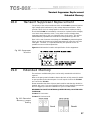
18.0
Transient Suppressor Replacement
The primary of the mains transformer within the TCS-80X is protected against
high voltage spike interference by two voltage dependent resistors. These
provide a short circuit to voltage peaks in excess of their maximum rating.
Should the TCS-80X be inadvertently connected to 3 phase line/line voltages,
or to 240V when selected to 120V, or any other incorrect voltage, these
suppressors are likely to fail in a protective short circuit mode. This will be
demonstrated by repeated mains fuse failure when powering up the unit.
Even in this case of extreme overvoltage, the TCS-80X are protected against
failure, and the simple removal of these suppressors will allow the unit to be
used again. However, it is important that they are replaced as soon as
possible to ensure continued protection.
Figure 18.1 indicates the location and specification for the suppressors.
Fig 18.1 Suppressor
location
19.0
Extended Memory
The maximum available delay time can be easily extended should this be
required.
Refer to the spare parts information sheet at the back of this manual for details
on part numbers for the relevant parts. You will require 2 off for the TCS-804
and 1 off for the TCS-803.
Please remember that these chips are static sensitive and that they should be
handled with care. If you are not familiar with the correct handling procedures
then we suggest you refer the installation to your local BSS dealer.
REMEMBER TO MOVE THE INTERNAL JUMPER CN10A/B, LOCATED NEAR
THE EPROM.
TCS-803: FIT IC42 ONLY
TCS-804: FIT IC42 and IC43.
Fig 19.1 Extended
Memory Jumper
Setting
37
Option Transformers
20.0
Option Transformers
Provision is made internally for transformers to be fitted to the electronically
balanced inputs if required. Refer to the spare parts information sheet at the
rear of this manual for details on required parts. You will need one transformer
for each channel. The transformers are easily fitted onto the main PCB in the
positions shown (See figure 20.1). The orientation must be such that the white
'spot' on the transformer corresponds with the ring printed on the circuit board.
Wire links LK101, LK102, LK201 and LK202 must also be cut.
Fig 20.1 Transformer
Option Location
38
Specifications
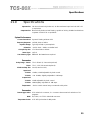
21.0
Specifications
Input section: 10k ohm electronically balanced, +2-dBu maximum input level via XLR 3-31
or equivalent.
Output section: Electronically balanced and floating, capable of driving +20dBu into 600ohms
or greater via XLR 3-32 or equivalent.
System Performance
Conversion method: Dynamic floating window PCM.
Frequency Response: ±0.5dB, 20Hz to 20kHz.
Dynamic Range: Typically 105dB, no pre-emphasis.
Distortion: ≤0.03% 20Hz - 20kHz at +10dBu level.
Group Delay Dev: ±7µS from 20Hz to 20kHz.
Stereo Sync: ±0.5µS.
User Memory Type: EEPROM. No batteries are required.
Parameters
Delay Range - Stereo: 75µS - 650mS. (1.3 seconds Optional).
Mono: 75µS - 1.3S. (2.6 seconds Optional).
Minimum Step Size: 10µS (3.4mm at 21°C)
Input Level
TCS-804: +10dBu, ±10dB adjustable by level control.
TCS-803: -9 to +20dBu, digitally adjustable in 1dB steps.
Output Level
TCS-803: ±10dB adjustable by level control.
TCS-804: ±6dB digitally adjustable in 1dB steps.
Temperature: -19°C to +44°C manual entry or automatic with probe.
Parameters
Remote pgm Select: 9 Pin submin D connector, 3 x 4 contact closure matrix for selection of 12
programs.
MIDI: IN, THRU, OUT 5 Pin 180° DIN connector.
Temperature Probe: 0.25" RTS jack socket for BSS probe.
39
Specifications
Display
Input Headroom: 7 step linear showing 0dB to +20dB.
Parameters: 4 digit plus unit/status LEDs.
Power
AC 50VA, 50-60Hz, 120v/240v selectable externally. Pluggable IED power
cord.
Dimensions/Weight
Dimensions: 482 x 44 x 228mm
19 x 1.75 x 9".
Weight: 4.5kg net.
Options
Transformer Balancing: Internal.
Memory Expansion: TCS-803 to 1.3 seconds.
TCS-804 MONO to 2.6 seconds.
TCS-804 DUAL CHN to 1.3 seconds per channel.
Temperature Probe: Allows automatic temperature compensation for delay time. Accurate to
±3°C.
Security Cover: Mechanical fixing to supplement electronic lockout.
40
Warranty Information
22.0
Warranty Information
This unit is warranted by BSS Audio to the original end user purchaser against
defects in workmanship and the materials used in its manufacture for a period
of one year from the date of shipment to the end user.
Faults arising from misuse, unauthorised modifications or accidents are not
covered under this warranty. No other warranty is expressed or implied.
If the unit is faulty it should be sent, in its original packaging, to the supplier
or your local authorised BSS Audio dealer with shipping prepaid.
You should include a statement listing the faults found. The unit’s serial
number must be quoted in all correspondence relating to a claim.
IMPORTANT
We recommend that you record your purchase information here for future
reference.
Dealer Name:
Dealer Address:
Post/Zip Code:
Dealer Phone No.:
Dealer Contact Name:
Invoice/Receipt No.:
Date of Purchase:
Unit Serial Number:
In keeping with our policy of continued improvement, BSS Audio reserves the
right to alter specifications without prior notice.
The TCS-80X was designed and developed by BSS Audio, Hertfordshire,
England.
Phone (+44) (0)1707 660667. Fax (+44) (0)1707 660755.
World Wide Web address: http://www.bss.co.uk
41
Index
Index
A
Applications
Audience Distances
Speaker Driver Placement
31
31
B
Bypass
19
C
Chassis/0v Link Removal
Connections
Control
Input
Output
35
15
14
15
D
Delay Time
Display
Errors
Distance
19
16
17
19
7
F
Front Panel
803
804
8
10
I
Input Level
803
804
Installation
19
20
12
L
Linking (804)
Relative Delay, Dual Channel
Relative Delay, Mono
Stereo Pairs
Lockout
42
37
34
17
O
Output Level
803
804
Output Mutes
19
20
21
P
Parameter Selection
Power Connection
Power Fusing
Powering Up
Program
Recall
Store
18
13
13
16
22
22
Rear Panel
803
804
8
10
S
Settings
Factory Default
Specifications
16
39
T
Temperature Probe
Transformers (Optional)
Transient Suppressor
36
38
37
U
29
28
27
23
Unit dimensions
Unpacking
Utility Menu
Master/Slave Transmit
MIDI Channel Select
Temperature
26
26
26
W
M
Master/Slave Operation
Temperature Linking
Transmit Off
26
26
R
E
Earthing Requirements
Transmit Program
Transmit Slave
Memory
Extended
MIDI
Mode Setting (804)
Warranty Info.
Wiring convention
12
7
25
24
24
41
14
User Notes
43
User Notes
44
User Notes
45
User Notes
46