1
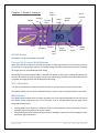
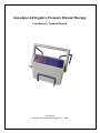
Genadyne A4 Negative Pressure Wound Therapy User Manual / Technical Manual User Manual Copyright Genadyne Biotechnologies, Inc. – 2008 Table of Contents Warnings ...................................................................................................................................................... iii Safety Summary ........................................................................................................................................... iii Warnings ........................................................................................................................................... iv Safety Standards ........................................................................................................................................... v Electrical ................................................................................................................................................... vi Servicing ................................................................................................................................................... vi Special Notes................................................................................................................................................ vi EMC Table ................................................................................................................................................... vii Precautions ............................................................................................................................................... - 1 Operating Precautions: ......................................................................................................................... - 1 Caution ...................................................................................................................................................... - 3 Contact Info............................................................................................................................................... - 3 Chapter 1: Introduction ............................................................................................................................ - 3 Console.................................................................................................................................................. - 4 Power Adapter/ Battery Charger .......................................................................................................... - 2 Battery................................................................................................................................................... - 3 Canister ................................................................................................................................................. - 4 Tube Connector..................................................................................................................................... - 5 Chapter 2: Clinical Applications ................................................................................................................ - 6 Contraindications .................................................................................................................................. - 6 Precautions ........................................................................................................................................... - 6 Indications for use................................................................................................................................. - 6 Chapter 3: Monitor Features .................................................................................................................... - 7 ON/OFF Button ..................................................................................................................................... - 7 Pressure UP/ Pressure DOWN Buttons ................................................................................................. - 7 YES / NO Buttons................................................................................................................................... - 7 MODE Button ........................................................................................................................................ - 7 Chapter 4: Operating Modes & Instructions............................................................................................. - 8 Power Up/Down the Device ................................................................................................................. - 8 i|Page E2.0.5 (01.06.2012) Therapy Mode ....................................................................................................................................... - 8 Adjusting Pressure ................................................................................................................................ - 8 Key Lock / Unlock .................................................................................................................................. - 8 Notification Logs ................................................................................................................................... - 8 Chapter 5: Cleaning and Maintenance ..................................................................................................... - 9 Cleaning................................................................................................................................................. - 9 Returning the Device: ........................................................................................................................... - 9 Canisters.............................................................................................................................................. - 10 Power Unit Casing ............................................................................................................................... - 10 Chapter 6: Ordering Supplies .................................................................................................................. - 10 Chapter 7: Servicing ................................................................................................................................ - 11 Opening /Closing the Unit................................................................................................................... - 11 Filter Change ....................................................................................................................................... - 11 Limited Warranty .................................................................................................................................... - 13 - ii | P a g e E2.0.5 (01.06.2012) Warnings DO NOT OPERATE THIS EQUIPMENT WITHOUT FIRST READING AND UNDERSTANDING THIS MANUAL. IF YOU ARE UNABLE TO UNDERSTAND THE WARNINGS, CAUTIONS AND INSTRUCTIONS, CONTACT A HEALTHCARE PROFESSIONAL, DEALER OR TECHNICAL PERSONNEL IF APPLICABLE BEFORE ATTEMPTING TO USE THIS EQUIPMENT. OTHERWISE INJURY OR DAMAGE MAY RESULT. Safety Summary This system has been designed to comply with the regulatory safety standards including UL 60601-1, CAN/CSA C22.2 No. 601.1-M90, CE 93/42/EEC Class IIa. Read All Instructions Prior To Use When using electrical devices, especially when children are present, basic safety precautions should always be followed, including the following. DANGER To reduce the risk of electrocution: 1. 2. 3. 4. 5. ALWAYS unplug this product immediately after using or when charging is completed. DO NOT use while bathing. DO NOT place or store product where it can fall or be pulled into a tub or sink. DO NOT Place or drop into water or other liquid. DO NOT reach for a product that has fallen into water. Unplug immediately. WARNING The use of external Accessories and cables other than those provided by Genadyne may result in increased Electromagnetic Emissions or decrease in Immunity of the Wound Vacuum System. When the Genadyne accessories (Type BF applied part) are used, patient leakage current will not exceed limits set for this Device (Class II). The USB port is blocked by tape. Removing the tape invalidates the Warranty. The use of the USB port is strictly limited to Genedyne Personnel. iii | P a g e E2.0.5 (01.06.2012) WARNING: Disregarding the information on safety of this device is considered ABNORMAL USE To reduce the risk of burns, electrocutions, fire or injury to persons: 1. This product should never be left unattended when plugged in. 2. Close supervision is necessary when this product is used near infants or children. 3. Use this product only for its intended use as described in this manual. DO NOT use attachments or kits not recommended by Genadyne. 4. NEVER operate this product if it has a damaged cord or plug, any missing components, is not working properly, has been dropped or damaged or has been dropped into water. 5. Keep the cord away from heated surfaces. 6. NEVER use while sleeping or drowsy. 7. DO NOT operate where aerosol (spray) products are being used or where oxygen is being administered. 8. The AC ADAPTER should be unplugged from the outlet when not in use. When unit is not going to be used for an extended period of time, store carefully in a cool, dry place. 9. The user SHOULD NOT attempt to service or repair the Wound Vacuum System, refer all servicing to Genadyne. No user serviceable parts inside. Warnings DO NOT OPERATE THIS EQUIPMENT WITHOUT FIRST READING AND UNDERSTANDING THIS MANUAL. IF YOU ARE UNABLE TO UNDERSTAND THE WARNINGS, CAUTIONS AND INSTRUCTIONS, CONTACT A HEALTHCARE PROFESSIONAL, DEALER OR TECHNICAL PERSONNEL IF APPLICABLE BEFORE ATTEMPTING TO USE THIS EQUIPMENT. OTHERWISE INJURY OR DAMAGE MAY RESULT. BEFORE PERFORMING ANY MAINTENANCE TO THE CONSOLE, DISCONNECT THE POWER CORD FROM THE WALL OUTLET. REFER SERVICING TO QUALIFIED PERSONNEL ONLY. GROUNDING RELIABILITY DEPENDS UPON A PROPERLY GROUNDED WALL OUTLET. DO NOT USE THE POWER UNIT IN THE PRESENCE OF FLAMMABLE GASES SUCH AS ANESTHETIC AGENTS. WARNING/CAUTION NOTICES USED IN THIS MANUAL APPLY TO HAZARDS OR UNSAFE PRACTICES WHICH COULD RESULT IN PERSONAL INJURY OR PROPERTY DAMAGE. iv | P a g e E2.0.5 (01.06.2012) PLEASE MAKE SURE THAT THE POWER ADAPTER IS PLUGGED INTO THE WALL BEFORE PLUGGING INTO THE UNIT. FAILURE TO FOLLOW THIS PRECAUTION MIGHT CAUSES DAMAGE TO THE UNIT. Safety Standards This system has been designed to comply with the regulatory safety standards including UL 60601-1, CAN/CSA C22.2 No. 601.1-M90, 93/42/EEC Class IIa. This system is internally powered with battery and externally powered with an approved Class II power adapter. v|Page E2.0.5 (01.06.2012) Electrical Before performing any maintenance to the Console, disconnect the power cord from the wall outlet. Refer servicing to qualified personnel only. Grounding reliability depends upon a properly grounded wall outlet. Do not use the Power Unit in the presence of flammable gases such as anesthetic agents. Servicing The GENADYNE A4 contains three user serviceable parts: - tubing, canister, and dressing. These parts are disposable and are easy to replace by users. If your system requires service, contact Customer Service for a return shipment authorization number. Packaged system in the original shipping box. Clean system components before shipment. Please refer to Chapter 6 (page 15) on how to clean the Console – unsanitary systems will be returned without servicing. Special Notes WARNING/CAUTION NOTICES USED IN THIS MANUAL APPLY TO HAZARDS OR UNSAFE PRACTICES WHICH COULD RESULT IN PERSONAL INJURY OR PROPERTY DAMAGE. vi | P a g e E2.0.5 (01.06.2012) EMC Table Guidance and manufacturer’s declaration – electromagnetic emissions The Genadyne A4 is intended for use in the electromagnetic environment specified below. The customer or the user of the Genadyne A4 should assure that it is used in such an environment. Emission Test RF emissions Compliance Group 1 The Genadyne A4 uses RF energy only for its internal function. Therefore, its RF emissions are very low and are not likely to cause any interference in nearby electronic equipment. Class B The Genadyne A4 is suitable for use in all establishments including domestic establishments and those directly connected to the public low-voltage power supply network that supplies buildings used for domestic purposes. CISPR 11 RF emissions CISPR 11 Harmonic emissions Electromagnetic environment - guidance Class A IEC 61000-3-2 Voltage fluctuations/ flicker emissions IEC 61000-3-3 vii | P a g e Complies E2.0.5 (01.06.2012) Precautions For your safety, always take the following precautions: • Regularly check the system when in use, for Console operation, battery status, dressing integrity and type/amount of exudates. • Keep the Power Unit away from sources of liquids and do not immerse in water. • Do not expose the system, especially the dressing kit, to naked flames, or other sources of ignition, such as cigarettes, etc. • Do not store the system in direct sunlight. • Disconnect the battery charger connector from the Console before cleaning and inspecting. • Do not use phenol-based solutions to clean the system. • Make sure the system is clean and dry prior to storage. • Only the Console, canister and dressing kit combinations as indicated by Genadyne Biotechnologies should be used. The correct function of the product cannot be guaranteed if incorrect Console, canister and dressing kit combinations are used. Operating Precautions: When operating, transporting, repairing or disposing of A4 devices and accessories, the risk of infectious liquids being aspirated, or contamination of the device assembly through incorrect use, cannot be eliminated. Universal precautions should be observed whenever working with potentially contaminated parts or equipment. As a condition of use, the A4 Wound Care System should only be used by qualified and authorized personnel. The user must have the necessary knowledge of the specific medical application for which NPWT is being used. The A4 Wound Care System should remain on for the duration of the treatment. If the patient must be disconnected, the ends of the tubing should be protected using the tethered cap. The length of time a patient may be disconnected from the A4 Wound Care System is a clinical decision based on individual characteristics of the patient and the wound. Factors to consider include the location of the wound, the volume of drainage, the integrity of the dressing seal, the assessment of bacterial burden and the patient's risk of infection -1-|Page E2.0.5 (01.06.2012) Ensure that tubing and Port Dressing is installed completely and without any kinks to avoid leaks or blockages in the vacuum circuit. Position the A4 Wound Care System and tubing appropriately to avoid the risks of causing a trip hazard. Whenever possible, the device and system tubing should be positioned level with or below the wound. -2-|Page E2.0.5 (01.06.2012) Caution ELECTROMAGNETIC COMPATIBILITY (EMC). This product complies with the requirements of applicable EMC Standards. The use of accessories not specified by the manufacturer may result in increased emissions by, or decreased immunity of, the equipment, affecting its performance. Contact Info Genadyne Biotechnologies Genadyne Canada EU Representative Obelis S.A. 16 Midland Ave Hicksville, NY 11801 USA 31 Tamara Place Unit #1 Brantford, ON N3P 1M8 CANADA Bd. General Wahis 53 1030 Brussels BELGIUM 1.800.208.2025 (Toll Free) 1.516.487.8787 (Tel) 1.516.487.7878 (Fax) 1.888.787.2811 (Toll Free) 1.519.770.0020 (Tel) 1.877.487.7878 (Fax) +32 (0) 2.732.59.54 (Tel) +32 (0) 2.732.60.03 (Fax) www.genadyne.com www.genadyne.ca www.obelis.net Chapter 1: Introduction This is your introduction to the Genadyne A4 Powered Suction Pump system. Use it to initially set up the system, and keep it as a reference for day to day use and as a guide to maintenance. The Genadyne A4 may provide a non-pharmacological, physical method of promoting wound healing and works by the local application of sub-atmospheric pressure (suction) across a wound. The Genadyne A4 system comprises:- • • • • • A Console which provides the suction. A disposable canister on the back of the Console to collect the exudates. A connector tube from the Console to the canister. A battery charger adapter. A dressing kit. -3-|Page E2.0.5 (01.06.2012) For more information about GENADYNE and other products please call us or visit our website: Warning ! Disregarding the instruction for suggested orientation may lead to potential contaminants entering inside the NPWT device! Console The Genadyne A4 Console is designed to work in horizontal (with the front face uppermost) and the vertical orientations. The Console is NOT designed to operate in the, horizontal orientation with the front face on the underside, or tilted at an angle to the vertical. Horizontal with Front Face Uppermost Tilted -4-|Page Vertical Horizontal with Front Face on Underside E2.0.5 (01.06.2012) FRONT VIEW Carry Handle LCD Screen Suction Connector Bed Hanger BACK VIEW IV pole Bracket Bracket for Canister holder -2-|Page E2.0.5 (01.06.2012) Power Adapter/ Battery Charger IEC-320 C8 Power Cord (Model# MPU30B-5) 19 VDC 1.58A 30W At times, the Console will not be connected directly to the power supply; instead, the Console operates from power provided by an internal rechargeable battery. An icon on the LCD screen indicates the battery charge status, and when it needs to be recharged. To recharge the internal battery in the Console:• Plug the power plug of the power adapter/ battery charger to the power inlet behind the Console. • Plug the power cord into a wall power supply. • The Console will continue to function normally while it is charging. • In event of a battery fault, the Console will still continue to function normally while being plug into the power socket. Battery The battery life for the Genadyne A4 was tested to last for more than 8 hours of usage per charge. The normal charge time is 3 hours. CAUTION: GENADYNE BIOTECHNOLOGIES will not be responsible for any problems or damage caused to the Console if a user connects any power source other than the supplied Power Adapter in the box. -3-|Page E2.0.5 (01.06.2012) Canister Canister Outlet (to Console) Canister inlet (from Dressing) Wire Ring Canister Cap The canister provided by Genadyne Biotechnologies is fitted to the back of the Console via the wire ring, and excess wound fluid is drawn into the sealed canister for subsequent disposal. The canister incorporates a 1.0 micron hydrophobic filter designed to remove potentially harmful organisms (which may originate in the wound) from the air expelled to the environment. -4-|Page E2.0.5 (01.06.2012) The canister can hold up to 800ml of fluid. The canister is for single use only. To dispose the canister, close the canister inlet with the canister cap to prevent the exudates and fluid from leaking. Tube Connector The tube connector is to connect from the Console to the Canister. Tube Connector -5-|Page E2.0.5 (01.06.2012) Chapter 2: Clinical Applications Contraindications When used for wound healing, the GENADYNE A4 is contraindicated in the presence of: untreated malnutrition, untreated osteomyelitis, malignancy, necrotic tissue, or exposed arteries, veins, or organs. Precautions Patients who might be taking following therapy should take precautions: untreated for malnutrition, anticoagulant therapy, suffering from difficult hemostasis, or non-compliant or combative. Indications for use The Genadyne A4 Wound Vacuum System is indicated for use in patients who would benefit from negative pressure wound therapy particularly as the device may promote wound healing by the removal of excess exudates, infectious material and tissue debris. -6-|Page E2.0.5 (01.06.2012) Chapter 3: Monitor Features On/Off Mode Pressure Up Lock/ Unlock Alarm Status Pressure Down Yes/Select No/Exit ON/OFF Button Date/ Time Therapy Mode Target Pressure LCD Screen Actual Pressure Battery Status This button is to turn the Console On and Off. Pressure UP/ Pressure DOWN Buttons When the Pressure Up button is pressed, the number of the Target Pressure will increase by one unit, for example an original target pressure is set at 80 mmHg, and when the pressure up button is pressed, the target pressure will be displayed as 81 mmHg. Meanwhile if the Pressure Down button is pressed, the number of the Target Pressure will decrease by one unit, for example an original target pressure is set at 81 mmHg, and when the pressure down button is pressed, the target pressure will be displayed as 80 mmHg. YES / NO Buttons ‘Yes’ button enables user to select a particular function to operate and set a certain desired value. ‘No’ button enables user to cancel a selected function or to exit a menu and go back to the main screen. MODE Button The ‘Mode’ button enables users to choose a function from a list that will be displayed in the LCD screen. The ‘Mode’ button brings users into a list of functions, such as Therapy Mode, Pressure Setup, Alarm Setup and Advance Setup. • • Therapy Mode has 2 functions, Continuous suction and Intermittent, where intermittent function maintains the suction pressure at a given interval. Advance Setup will have functions to setup the time, backlight, contrast of the LCD, usage hour, and notification logs of the device. -7-|Page E2.0.5 (01.06.2012) Chapter 4: Operating Modes & Instructions Power Up/Down the Device To turn the device ON, press the on the display. Press the same button. The LCD will be lighted up with a huge numerical number button to turn the device OFF. Therapy Mode To verify therapy mode, check on the Symbol on the Top the LCD Screen. Symbol □ C represents Continuous, and Symbol I represents □ Intermittent. If you want to change the Intermittent time interval, please follow these steps: Mode > Therapy Mode > Intermittent (Select) > Time (Up /Down to Increase or Decrease Time) > YES Button to Save Adjusting Pressure To increase or decrease the negative pressure, press on the Up / Down button to Increase or Decrease the negative pressure. The desired pressure will be displayed on the LCD Screen. Each patient will have their own prescribe pressure range. Key Lock / Unlock To lock / unlock the keypad, follow these sequences of button pressing: Hold on to the YES and NO button for 5 seconds and release it. (Hold)YES + NO for 5 seconds Notification Logs The GENADYNE A4 allows user to retrieve information on past alarms episodes with time and date stamps. To check, please follow these steps: Mode > Alarm Setup > Fault Log > Press Mode to toggle for time and date stamps -8-|Page E2.0.5 (01.06.2012) Chapter 5: Cleaning and Maintenance Cleaning The following shall be the instructions given to the user concerning cleaning: Adherence to facility directives concerning hygiene is of prime importance. Only use low level diluted form of disinfectants or cleaning agents when cleaning the A-4. Use damped cloth to clean the pump. Be cautious when cleaning because no liquids should enter the power unit. If the liquid goes inside of the power unit, it might cause the unit to malfunction or damage the mechanics. Dry with a separate soft cloth. Return the device to Genadyne or distributor for cleaning and disinfecting after every patient for preventive maintenance. Do not open the Device if training was not provided. It is the responsibility of the facility / distributor to request for in house training if cleaning and disinfecting is done in house. Genadyne offers free training and in service upon point of sale. Do not use solvents or abrasives. Do not immerse any part of the A-4 in fluid or use an unnecessarily wet cloth. Please contact your distributor if any liquids penetrated the device. Returning the Device: The following shall be the instructions given to the user concerning the return of the device to Genadyne. For any returns or rental returns, prior to returning the device to your representative, the device must be cleaned in line with the steps laid out under the cleaning section of this manual. All used canisters have to be disposed. Disposal of used canisters should follow facility protocols or local ordinances relating to the handling of potentially infected or bio-hazardous materials. -9-|Page E2.0.5 (01.06.2012) Canisters Canisters are recommended to be replaced every week and should not be reused from Patient A to Patient B. Used canisters should be disposed according to the guidelines for handling infected or biohazardous materials. Facilities should follow local governing guidelines regarding sanitation of disposed device components. Power Unit Casing Only use diluted form of disinfectants or cleaning agents which is compatible with the casing. Use damped cloth to clean the pump. Be cautious when cleaning because no liquids should enter the power unit. If the liquid goes inside of the power unit, it might cause the unit to malfunction or damage the mechanics. Chapter 6: Ordering Supplies To order for more supplies, please call your local distributor. - 10 - | P a g e E2.0.5 (01.06.2012) Chapter 7: Servicing When the pump is not functioning properly, first monitor the small numbers on the LCD screen for the actual pressure. When NOT connected to the tube connector, the actual pressure will cycle up and down within the range of +/- 40 mmHg off the target pressure. When CONNECTED to the tube connector with no dressing in place, the actual pressure will stay below 20 mmHg at any given time. If the actual pressure does not go down below 20 mmHg after the tube connector has been connected with no dressing in place, this means that there is a blockage or kink of the tubing inside the pump. Refer to Opening /Closing the Unit and Filter Change at the bottom part of this chapter. If the pump does not run when you turn the unit on, this means the pump is malfunctioning. Please contact your nearest service center to arrange a service of the pump. If the actual pressure is showing a number of 256 mmHg or more constantly regardless of the tube connector status, this means that the pressure sensor is malfunctioning. Please contact your nearest service center to arrange a service on this pump. Opening /Closing the Unit To open the unit, all you need is a flat head screw driver. First, peel off the warranty sticker on the side of the console unit. Use the flat head screw driver and press into the opening on both sides. A “Click” sound will be noticeable. Please be aware that once the warranty sticker has been peeled off, this will void the manufacturer’s warranty on this unit. To close the unit, slide down the upper enclosure to the bottom enclosure. When pressed hard on both sides till 2 (two) “Click” sound is heard. Filter Change To change the filter, first you need to have an extra filter on hand. To order additional filter, please contact your nearest service center to order them. Use a tubing cutter or scissors and cut both ends of the filter. Replace the new filter by fitting the tubing onto both ends of the filter. - 11 - | P a g e E2.0.5 (01.06.2012) Chapter 8: Product Specifications VACUUM PUMP Service Life (est.) Maximum Vacuum : 5,000 hours : 230mmHg SUCTION CAPACITY 5 Liters per Minute DIMENSIONS/WEIGHT Dimension : 8” (L) x 7” (W) x 3” (H) (200mm x 177mm x 76mm) Weight : 3lbs (1.36Kg) Canister is capable of holding 800CC of fluid ELECTRICAL REQUIREMENT Power : 19 VDC, 1.57A Battery Type : Li-Ion rechargeable batteries Recharge Time : 3 Hours Safety : CSA, IEC 60601 ENVIRONMENTAL CONDITIONS Operating Conditions : 18°C to 34°C, 65°F to 94°F Relative Humidity : 10% to 95 STORAGE AND SHIPPING CONDITIONS Ambient Temperature : 0°F to 110°F, -18°C to +43°C Relative Humidity : 10% to 95 % PATIENT PROTECTION Type BF COMPLIANCE UL 60601-1 IEC 60601-1 IEC 60601-1-2 CAN/CSA C22.2 No. 601.1 - 12 - | P a g e E2.0.5 (01.06.2012) Limited Warranty Genadyne NPWT Limited Warranty & Preventative Maintenance Genadyne warrants, for a period of two years from the date of sale of the device, that the device (“Product”) shall perform to specifications as stated in the product manual. This warranty covers all internal components, with the exception of the battery and internal tubing, which are covered win the preventative maintenance program. In the event of failure to perform to specifications, Genadyne shall repair or replace the Product, at its discretion, and at no charge to Customer in accordance with its repair policy as stated in the Product Terms and Conditions. In order to keep this product warranty in effect, Customer must promptly notify Genadyne of any defects in writing within thirty (30) days of discovery of such defects or within two (2) years of the date of sale of the device. Product must also, have scheduled diagnostic maintenance every 6 months or 4000 hours, whichever comes first. Failure to comply will void warranty. Preventative maintenance consists of full inspection and diagnostics of unit, replacement of internal tubing and battery if necessary, replacement of Double O-rings, replacement of odor patches and cleaning of the inside and outside of the unit. This maintenance insures proper continued performance from the unit, as well as maintaining the indicated battery run time. This warranty does not cover: (i) Products packaged or labeled by someone other than Genadyne or its authorized agents; (ii) Products not used in compliance with the specifications in the product manuals; (iii) Products used in conjunction with components, wound dressing kits or canisters not specified for use with Genadyne wound vacuum system; (iv) Defects due to misuse, reprocessing, alteration, unauthorized repair or negligent handling, or defects due to lack of care by the Customer, or assigned user of the Product including but not limited to storage, handling or cleaning. OTHER THAN THE WARRANTY STATED ABOVE, GENADYNE, MAKES NO REPRESENTATIONS OR WARRANTIES OF ANY KIND WHATSOEVER, EXPRESS OR IMPLIED, INCLUDING BUT NOT LIMITED TO REPRESENTATIONS OR WARRANTIES WITH RESPECT TO THE MERCHANTABILITY, OR FITNESS OR SUITABILITY FOR ANY PURPOSE OR USE BY CUSTOMER OF THE PRODUCT. IN NO EVENT SHALL GENADYNE BE LIABLE FOR ANY ANTICIPATED PROFITS, OR OTHER INDIRECT, INCIDENTAL OR CONSEQUENTIAL DAMAGES OF ANY KIND WHATSOEVER OR LOSS OF TIME INCURRED BY THE CUSTOMER WITH THE PURCHASE OR USE OF THE PRODUCT. FURTHER, GENADYNE SHALL IN NO EVENT BE LIABLE FOR ANY EXEMPLARY OR PUNITIVE DAMAGES. - 13 - | P a g e E2.0.5 (01.06.2012)