1
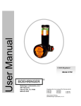
Model 3950 CSR Cell Salvage Regulator Boehringer Laboratories, LLC 300 Thoms Dr. Phoenixville, PA 19460 800-642-4945 3950.003 Rev Released June 2012 P/N 34048 User Manual Cell Salvage Regulator 1 of 13 WELCOME Congratulations on your purchase of the Boehringer CSR Regulator. We consider our regulators to be the best in the world. We are confident it will provide you with reliable, trouble-free, safe patient care and low cost of operation. This product is intended for use by clinicians properly trained in the use of suction for the collection of shed blood for cell salvage. The product is intended for use on the order of a physician. Please read these instructions carefully. Contents Definition of Terms ................................................................................................................... 3 Indications ................................................................................................................................ 3 Contraindications ...................................................................................................................... 4 Safety Information .................................................................................................................... 4 Operation/Features .................................................................................................................. 5 Theory of Operation ................................................................................................................. 6 Installation ................................................................................................................................ 6 Pre-Use Check ......................................................................................................................... 7 Mode Selection ......................................................................................................................... 7 Clinical Use............................................................................................................................... 7 Maintenance ............................................................................................................................. 8 Cleaning & Disinfection ............................................................................................................ 8 Troubleshooting ........................................................................................................................ 8 Specifications ........................................................................................................................... 9 Warranty and Repair ................................................................................................................ 9 3950.003 Rev Released June 2012 P/N 34048 User Manual Cell Salvage Regulator 2 of 13 Definition of Terms and Symbology Parts ......................................................................................................................................... 13 VACUUM Air or other gases at a sub atmospheric pressure typically expressed as mmHg. SUCTION A use of vacuum that causes a fluid or solid to be drawn into an interior space or to adhere to a surface because of the difference between the external and internal pressures. Alerts the user to the presence important operating and maintenance instructions in the literature accompanying the device. WARNING Alerts user to actions or conditions that could result in injury to user or patient. CAUTION Alerts user to actions or conditions that can cause damage to the device or may result in substandard performance of the device or system. IMPORTANT Indicates an action that is emphasized to ensure proper operation of equipment. OFF Supply suction is off and patient circuit is vented to atmospheric pressure. REG Supply suction is on and regulated output is controlled to prescribed setting. LINE Supply suction is on and regulation is bypassed to deliver maximum suction to collection circuit. This level of suction should only be used in emergency field clearance scenarios, as unregulated wall suction can rapidly lyse red blood cells. Lo Spike: Accuracy of regulation depends primarily on the ability to provide a consistent level of vacuum under changing flow conditions. Involuntary pneumatic biopsy, or tissue damage, can occur when high levels of vacuum are applied to delicate tissue. With a Boehringer regulator, you can depend on very low “spike” compared to our competitor’s models. "Spike" is the variation in indicated suction as flow in the collection circuit changes from an a free flowing condition to an occluded condition. We measure spike as the change in indicated suction from full flow to a no flow condition using a typical collection circuit with a 14 French catheter. To test, set the regulator to 50 mmHg flowing, and then allow occlude the 14Fr catheter. The change in the indicated suction level is "Spike". Boehringer regulators are checked on the assembly line to meet a specification of less than 10% of the indicated setting, for example 5mmHg spike at a 50 mmHg setting. An evaluation of a regulator’s spike allows one to determine whether the device is truly “regulating”. A safe and reliable regulator should regulate to its set position regardless of variable flow conditions. PARALLAX Inaccuracy caused by observational position of an indicating element (pointer) to a reference element (scale). Indications for Use This product is intended for use by or on the order of a physician. It is to be used by individuals who are properly trained in the use of Intraoperative Autotransfusion cell salvage equipment. The Boehringer CSR Controller was designed to provide accurate control of wall suction from 20-200mmHg for use in vacuum blood collection for intraoperative autotransfusion using cell salvage devices. 3950.003 Rev Released June 2012 P/N 34048 User Manual Cell Salvage Regulator 3 of 13 ositive pressure > 10 cmH2O. Contraindications This device is designed and sold for use only as indicated Safety Information WARNING! This product is intended for use by or on the order of a physician. It is to be used by individuals who are properly trained in medical suctioning procedures. Please read these instructions carefully. A High Flow Bubble Barb fitting is provided to connect the regulator to a central suction source. It is strongly recommended that this product be used in conjunction with connection kits P/N 3941, 3942 or 3943. These kits include braid reinforced tubing suitable for suction service. If you opt not to connect your device in this manner, braid reinforced tubing must be used to preclude the possibility of suction tubing collapse during extended periods of use. The hose supplying suction to the regulator should have a vertical orientation to reduce the possibility of kinking over time. Any deformation of this tubing may be indicative of a reduction in flow to the suction regulator and accompanying patient circuit. Always verify the regulator is attached to an appropriate source of suction, and that suction is present, before attaching a patient collection circuit. This can be verified by turning the control valve to REG, and adjusting the control knob to increase suction. The presence of suction can be audibly heard from at the patient port of the regulator. Suction regulators must only be attached to vacuum systems. nitrogen, or oxygen sources. Suction catheters, collection canisters and suction tubing must be carefully evaluated and selected to ensure adequate function for the specific clinical environment and intended field of use. Always verify regulator operation (Spike, see page 4 for details) before use on a patient. Verify operation by establishing the desired vacuum level with the collection circuit and suction catheter attached to the regulator. Occlude the suction catheter and note that the indicated vacuum does not rise by more than 10% of the original setting. 3950.003 Rev Released June 2012 P/N 34048 User Manual Cell Salvage Regulator Do not attach to compressed air, 4 of 13 Operation FEATURES Patented Linear Gauge: Allows accurate readings from 180° field of view and never requires calibration. Each range has unique color-coding Adjusting Knob: Extra large, easy grip knob turns COUNTER-CLOCKWISE (direction of arrow) to increase suction setting and CLOCKWISE to decrease suction setting Integral Trap Bottle: Available for the 38XX models. Provides fluid overflow protection utilizing a precision float mechanism . Dual Inlet: provides secondary inlet for attachment of a second collection wand for high loss conditions Safety Release: Thumb spring that must be depressed to turn Mode Selector Valve to LINE Mode Selector Valve: Square knob to easily switch between operating modes. 3950.003 Rev Released June 2012 P/N 34048 User Manual Cell Salvage Regulator 5 of 13 THEORY OF OPERATION The CSR regulator incorporates a number of features that provide for effective suction in cell salvage procedures Precision regulation is accomplished via a spring opposed diaphragm assembly that references atmosphere against an adjustable spring and piston assembly. The device incorporates large ports for minimal spiking of setting upon occlusion. Suction output is indicated by an easy to read linear gauge that also consists of spring and diaphragm assembly configured in an intuitive manner that never needs calibration. The CSR regulator incorporates an overflow protection device with dual inlets for high blood loss applications where multiple collection reservoirs are required. INSTALLATION The model 3950 CSR regulator is supplied with a high flow bubble barb for attachment to wall suction. Only braid reinforced tubing suitable for suction service should be used when connecting this to a central suction supply, it is strongly recommended you utilize connection kits 3941, 3942 or 3943. Inappropriate tubing could lead to a reduction in flow and compromise patient safety. The tubing should exit the fitting in a downward vertical orientation to minimize the possibility of kinking the supply tubing over time. The patient connection must be connected to an appropriate collection reservoir, do not draw patient materials directly into this line. Use the integral IV Pole Mount to attach this unit to the mast of your cell salvage machine. Integral IV Pole Mount: Tighten to the mast of your cell salvage machine here. Supply Connection Port: Connect Supply tubing to this port. Patient Connection Ports: Disposable connection tubing can be attached to these ports. 3950.003 Rev Released June 2012 P/N 34048 User Manual Cell Salvage Regulator 6 of 13 MODE SELECTION Safety Release OFF: With control valve in the OFF position, suction is off and the collection circuit is returned to atmospheric pressure by an internal vent port, a special feature of the Boehringer design. REG: With control valve in the REG position, wall suction may be controlled to a specific level by turning the large adjusting knob in the direction indicated. A spring opposed diaphragm assembly precisely controls the level of suction provided at the lower port of the Regulator within the range of the gauge. This assembly "senses" changes in the patient collection circuit and makes appropriate adjustments to maintain the suction level that has been selected. Regulated settings are verified by the large, easy to read gauge. Model 7800 regulators incorporate a safe upper limit so they will not deliver any more than 230mmHg in this setting. LINE: With control valve in the LINE position, the regulating mechanism is bypassed. Full wall suction is applied to the patient collection system through the lower port of the Regulator. The LINE suction mode is engaged by depressing the safety spring release and rotating the control valve to the line position. LINE setting is verified by the exposure of the "LINE" warning at the bottom of the gauge label. CAUTION! Full line suction may cause damage to sensitive tissue and should only be used in emergency situations. CLINICAL USE Follow collection canister manufacturer’s instructions regarding proper set up and use. Attach ¼” suction line to the un-switched inlet to the CSR regulator. Adjust suction to 100mmHg. Increase suction as necessary to maintain adequate flow from the surgical field. Should a second reservoir be required, attach to the switched inlet using ¼” suction line and open the ¼ turn valve to permit flow. MAINTENANCE Your Boehringer Regulators have been designed to provide years of trouble free operation. Most service activity is the result of aspiration of bodily fluids or other foreign materials into the regulator. Your 3900 series regulator is equipped with patent pending Air Curtain Protection to provide isolation of critical control elements from the inadvertent intrusion of foreign contaminants. The routine use of an appropriate collection canister greatly reduces needed service. To determine your cleaning/maintenance schedule: Periodically inspect the overall condition of the instrument. Test the gauge accuracy and check the instrument function as described under ‘Test’. Simply clearing the small orifices in the gauge view tube and the regulator body can remedy many performance conditions (see troubleshooting). Return to service if the instrument performs appropriately per the ‘Test’ requirements. Based on data from your periodic inspections, determine a cleaning/maintenance schedule appropriate for the operational conditions of your facility. Clean, inspect, lubricate, and test based on your schedule and according to the Instrument Cleaning and Disinfection, Instrument Lubrication and ‘Test’ section outlined below. Please refer to Boehringer document 7700.192, Boehringer Suction Regulator Recommendations for Decontamination and Autoclaving for guidance. This information is available online at www.boehringerlabs.com, or toll-free at 1-800-642-4945. 3950.003 Rev Released June 2012 P/N 34048 User Manual Cell Salvage Regulator 7 of 13 DISASSEMBLY Regulator: 1. Back out dog point screw on diaphragm housing assembly with 1/16 hex wrench. 2. Unscrew diaphragm housing from regulator body. 3. Remove valve retaining screw and spool retainer with 5/32 hex wrench. Pull out control valve. The control valve is factory matched to the particular regulator body. If multiple units are disassembled, take care to keep like parts mated. 4. In the unlikely event suctioned material should enter the regulator diaphragm housing, it will be necessary to disassemble and scrub the unit as follows: a. Remove quad seal and Shroud by hand, then remove the lens cap retaining ring and lens cap and lens cap disc backer. b. Push out regulator diaphragm by pressing on piston/stem assembly. c. Remove piston/stem assembly and housing spring. 5. Remove the jar from the trap bottle manifold and release the float assembly. Gauge: 6. Remove the retaining ring using retaining ring pliers. From the front of the gauge, use thumb to rotate and loosen view tube. Then remove view tube-piston-diaphragm assembly. 7. Remove the lower lip of the diaphragm from outside of the view tube, and slide out the diaphragmpiston assembly. 8. Remove the upper diaphragm lip from the top of piston, and slide diaphragm off piston. 9. Remove gauge spring. NOTE: It is not necessary to remove the gauge body or the trap manifold from the regulator body prior to cleaning. IMPORTANT: Always clean the unit prior to assembly. See Cleaning and Disinfection for details. ASSEMBLY Assembly and Lubrication (See Fig. 1) After disassembling and cleaning the instrument, assemble and lubricate as follows. Parts are available from Boehringer Laboratories, LLC and may be ordered by part number (P/N). Part numbers are found in figure 1 at the end of this manual. Regulator: 1. Lubricate control valve (OFF, REG, LINE) over entire mating surface with synthetic lubricant (P/N 1895). 2. Rotate valve as you insert it into the body. Remove the valve and inspect for dry areas. The valve must have a thin layer of lubricant over its entire diameter without excess in the cross ports. 3. Lubricate the threaded sleeve in diaphragm housing and U-cup with a light coat of synthetic lubricant (P/N 1895). 4. Assemble diaphragm housing in reverse order of disassembly. Do not lubricate the stainless steel shaft of the piston/stem assembly or the inside of the threaded sleeve. 5. Inspect quad ring seal for cuts or wear. Replace if needed. 6. Assemble unit in reverse order of disassembly. Place housing spring on piston/stem assembly and then insert through diaphragm housing assembly. 7. Cover piston/stem assembly with lens cap disc backer and lens cap and snap lens cap retaining ring into groove. 8. Install shroud to piston stem it will snap into its correct position. Assemble quad seal to stem, then screw the housing into body fully. 9. Tighten dog point screw to retain diaphragm housing on regulator body groove. Typically this is screwed all of the way in, and backed out ½ - ¾ of a turn. Ensure this screw does not drag as the regulator setting is adjusted. 10. Insert the control valve and position the spool retainer before securing it with the valve retaining screw. 3950.003 Rev Released June 2012 P/N 34048 User Manual Cell Salvage Regulator 8 of 13 11. Reassemble the float assembly and screw the trap bottle back into place. Gauge: 12. Slide large end of diaphragm over piston until top ring snaps into groove in piston. Be certain the top bead of the diaphragm is completely engaged into the groove of the piston. CAUTION: If the diaphragm is not seated properly it will rub against the view tube and may lead to premature failure of the gauge. 13. 14. 15. 16. 17. 18. Slide view tube over diaphragm-piston assembly. Roll edge of diaphragm around bottom of view tube and into groove. Make sure there are no folds or twists and that diaphragm is smooth. Insert gauge spring into piston/view tube subassembly. Slide piston subassembly with spring up (and gauge body facing down) into gauge body. The spring should sit in the pocket at the bottom of the gauge body. Press until view tube assembly rests on shoulder in gauge body. Assemble retaining ring into groove in gauge body. IMPORTANT: Always clean the unit prior to assembly. See Cleaning and Disinfection pg 10 for details. IMPORTANT! Always test the reassembled unit after each maintenance procedure. See the Test section for exact test procedure. TEST 1. With the control valve in the REG or CONTIN position and a collection system attached with a 14 Fr. catheter, regulator should control vacuum from 10-100% of full scale (FS). 2. With the control valve in the REG or CONTIN position and housing turned all the way off, with suction port occluded, gauge should read zero. 3. With the control valve in the REG or CONTIN, adjust regulator to the middle of the scale and occlude the catheter. Gauge movement should be less than 10% of the setting. This measurement is called spike. 4. The gauge should be accurate to 5% of full scale (FS) for any measurement within the range of the scale. If this is not the case, please return the gauge to the manufacturer for repair/replacement. CAUTION: Inaccurate gauge calibration may lead to a high suction condition applied to the patient. 5. With the control valve in the OFF position, suction should be at atmospheric and gauge should read zero. With suction port occluded, gauge should read zero. 6. With the control valve in the REG or CONTIN position, with an appropriate collection system attached (>800cc capacity) set the Regulator to the middle of the scale and turn control valve to OFF, then back to REG or CONTIN. Gauge indicator should not travel more than 20% past the set point before settling at the desired level. 7. A final, important step in instrument maintenance is the identification of the instrument. This step confirms that a qualified individual performed service to accepted procedures and approved master gauges. An ID tag should accompany the instrument, which indicates (as a minimum): date of service, individual performing the service and the date of next service. CAUTION: Have the regulator factory serviced if not performing to specifications. See Warranty and Repair for details on getting your instrument factory serviced. 3950.003 Rev Released June 2012 P/N 34048 User Manual Cell Salvage Regulator 9 of 13 4 TROUBLESHOOTING Your CSR regulator has been designed for years of trouble-free service. Should you experience difficulty that is not the result of damage to the instrument, the most likely cause is aspiration of dirt and/or fluids into the Regulator. Symptom Probable Cause Solution Instrument fails to provide suction at the patient port. The supply or patient fittings are clogged, or the incoming suction tubing is collapsed or kinked. Replace or clean the fittings. Replace the incoming suction line. Instrument fails to provide suction at the patient port. The secondary inlet is open Turn the ¼ turn valve to the off position Gauge doesn't respond to changes in suction (via control valve or adjustment knob) Gauge diaphragm is improperly sealed on the gauge piston and/or view tube Reference 3700.044. Gauge piston is discolored. Material has entered the inside of the device. Instrument is contaminated. Please return to the factory for service. Instrument will not shut off or exhibits high spike. Dried fluids may have cut the quad ring seal. Please return to the factory for service. Instrument fails to regulate suction Piston/Stem surface is binding with foreign matter Please return to the factory for service. Audible sound coming from safety port on safety interrupter Material has entered the inside of the device. Instrument is contaminated. Please return to the factory for service. Boehringer Tech Bulletin SPECIFICATIONS Inlet and outlet fittings: 1/8 NPT, High Flow Bubble Barb (P/N 2469) Gauge accuracy ANSI Class B, ± 5% FS (± 3 mmHg) Regulation Accuracy: ±10% FS from full flow to zero flow with 14 FR catheter attached. Leak rate in OFF position: less than 1 cc/min Materials: polycarbonate, hard-anodized aluminum, stainless steel, Buna rubber, acetal copolymer. Model Regulation Range User Selectable Modes Wt. (lb)* H x W x D (in) 3950 20-200 mmHg Off, Regulated Control and full line 2.30 lbs 9 /4” x 6” x 7 /2” 1 1 Operating and Storage Limits We recommend that Boehringer Suction regulators be operated and stored at controlled conditions that typically reflect the medical facility environment. 3950.003 Rev Released June 2012 P/N 34048 User Manual Cell Salvage Regulator 10 of 13 Warranty and Repair Boehringer Laboratories, Inc. guarantees your CSR regulator for TEN years from the date of manufacture. Boehringer Laboratories, Inc. warrants to the original purchaser, new suction regulators purchased directly from Boehringer Laboratories, Inc. or from an authorized dealer or representative. This warranty guarantees the suction regulators to be free from functional defects in materials and workmanship. We also guarantee that our suction regulators will meet our published specifications. All regulators returned for repair shall be clean and free from contamination prior to shipment. This requirement is for the safety of our employees as well as to comply with Federal Law prohibiting the shipment of unmarked biohazard materials. If units are returned contaminated, a cleaning charge may result. A service charge may be assessed on any unit returned that shows evidence of gross abuse. Boehringer Laboratories, Inc. is the only authorized warranty service center for your CSR regulator. This warranty excludes acts of God, fire, flood and acts of war, terror or insurrection. Boehringer Laboratories’ sole and exclusive remedy under this warranty is limited to repairing and/or replacing the suction regulator. There are no other express or implied warranties beyond these warranties set forth above. At Boehringer Laboratories, we are committed to lowering your suction regulator costs of operation! A Return Material Authorization Number (RMA) must be obtained prior to returning a unit for service. Please contact Customer Service at Boehringer Laboratories, LLC 800-642-4945 [email protected] 300 Thoms Dr Phoenixville, PA 19460 www.boehringerlabs.com Covered under one or more of the following Boehringer patents (Additional Patents Pending): 6,264,890 6,228,056 5,992,239 5,879,624 5,409,491 5,354,262 5,203,778 2012 Boehringer Laboratories, Inc.© 3950.003 Rev Released June 2012 5,372,593 Boehringer is a trademark of Boehringer Laboratories, Inc. P/N 34048 User Manual Cell Salvage Regulator 11 of 13 When calling for replacement parts, please specify the regulator model number and lot number. (Exploded view shown on next page) Part Number Description Part Number Description 33038 33040 33042 33610 33036 33041 33043 1468 1454 1465BK 33930 33909 33761 Retaining Ring, XL Gauge View Tube, XL Gauge Diaphragm, XL Gauge Linear Gauge, O-Ring Piston, XL Gauge Spring, 0-200 XL Gauge XL Gauge Fastener Valve Retaining Screw Spool Retainer Lens Cap Retaining Ring Lens Cap Lens Cap Disc Backer Diaphragm Housing Assembly 1466 2297 33768 1479 33764 1461 1484 34056 9086 1458HC 353 1453HC Regulator Diaphragm Piston Assembly Housing Spring Dog Point Screw Shroud Quad Seal U-Cup Bi-Port Trap Bottle Assembly IV Pole Mount Bracket Assembly Regulator Body* O-Ring Control Valve* * The Regulator Body and Control Valve is factory matched. Please call for details regarding replacement. 3950.003 Rev Released June 2012 P/N 34048 User Manual Cell Salvage Regulator 12 of 13 Part Number Description Part Number Description 34054 33783 34045 33700 33699 33698 34059 Trap Bottle Manifold Manifold to Body Screw Ball Valve Umbrella Float Shield Jar 33282 (2 per assembly) 33280 (2 per assembly) 33705 33789 33702 33704 90˚ Street Elbow Bubble Barb Gasket 116 O-ring 225 O-Ring 0.0625 x 0.75 dowel rod 3950.003 Rev Released June 2012 P/N 34048 User Manual Cell Salvage Regulator 13 of 13