1
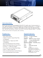
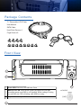
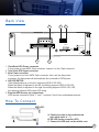
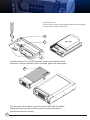
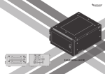
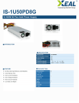
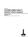
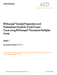
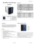
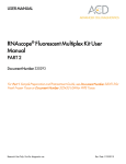
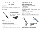
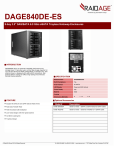
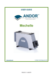
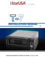
iStar, Good Start!
INSTALLATION MANUAL
FOR MORE INFORMATION, PLEASE VISIT WWW. I STARUSA .COM
C opyright
Copyright © 2006 by iStarUSA, Inc., all right reserved. No part of this publication
may be reproduced, transmitted, transcribed, stored in a retrieval system, translated
into any language, in any form or by an means or otherwise, without the prior written
permission of I-Star USA Inc. 11911 Clark St. #C, Arcadia, CA 91006.
iStarUSA Inc. reserves the right to make modification and additions to this product
and manual without notice or taking any liability.
Tr ademarks
iStarUSA, ImageShape, and D-Storm are all registered trademarks of iStarUSA, Inc.
All other trademarks herein are properties of their respective owners.
D i sclaimer
iStarUSA Inc. assumes no liability for errors or omissions in this document. Nor dose
iStarUSA Inc. make any commitment to update the information contained herein.
Pictures in this document are for demonstration purpose only and may not be the
same as the actual product.
I
S a fety Instructions
Please read this section carefully and follow the instructions for you own safety and
proper use of the device. It also contains information on approval and interference
suppression of your machine.
Please pay attention to the warnings and instructions on the device and in the
manual.
In order to maintain this condition and ensure safe operation, users must follow the
instructions and warnings contained in this manual.
The device must be used in accordance with the instruction for use.
The electrical installation condition in the room must correspond to
the requirements of the respective regulations.
Take care that there are no cables, particularly mains cables, in
areas where persons can trip over them.
Do not use a main connection in sockets shared by a number of
other power consumers. Do not use an extension cable.
Only use the supplied cable.
The unit is complete disconnected from the power source, only
when the power cord is disconnected from the power source.
Therefore the power cord and its connectors must always remain
easily accessible.
Do not setup the device in the proximity of heat sources or in a
damp location. Make sure the device has adequate ventilation.
All plugs on the connection cables must be screwed or locked to
the housing.
Do not touch the board or any other sensitive components without
all necessary anti-static protections.
FOR MORE INFORMATION, PLEASE VISIT W W W.IS TA R U S A.C O M
iStarUSA Acessories Series
II
Ta ble of Contents
Introduction …………………………......……………..1
Features ……………………………………….....….....1
Specifications …………….….……………....………..1
Package Contents …………..……………...…………2
Installation ………………………………….....…….....4
Technical Support ………………………....……….....5
Warranty Information …………………....……..…….5
III
I n t roduction
Military type aluminum hot-swappable iStarUSA T-7 mobile rack. Unique compact in
size, high performance SATA 2.0 interface up to 300mb/s transfer rate. T-7 is tough in
strength, but flexible in functionality. Additional cooling fan provide extra cooling in
worst operating condition. Indicator LEDs enable monitor power and hard drive activities. Security lock prevents intrusion and theft to the most important data. T-7 military
mobile rack construct with quality and versatility.
F e atures
Specification
:: SATA to SATA Interface
Model No. T-7 (Rhino RJ Series)
Drive Bays 1 x 5.25"
Interface
SATA 2.0 Hot-Swap Capable
Cooling
1 x 40mm Ball Bearing Fan
Material
All Aluminum Design
Dimensions (WxDxH) 146 x 190 x 42 mm
Color
Black
Cable
SATA Cable Included
Weight
3.5 lbs.
:: Cableless Connection, Support Plug & Play,
Hot-Swappable
:: High Performance - Support up to SATA
2.0 300MB/Sec
:: With 15pin SATA and 4pin Power Connector
:: Military Grade Quality Aluminum Frame & Tray
:: Front Fan x 1 - for Best Air Ventilation
:: Point to Point, Free from Master/Slave Setting
:: Unique 7.5” Depth Compact Size
:: Power Control & Security Key Lock That Reduces
From Potential Electronic Points of Failure
FOR MORE INFORMATION, PLEASE VISIT W W W.IS TA R U S A.C O M
Operating Attitude: 15,000 feet
Power Supply: 3U, 2U Redundant
Temperature: 0-50C (operating) 1-70C
(storage)
Humidity: 5-95%, non-condensing
Safety Standard: FCC/CE
iStarUSA Accessories Series
1
P a ckage Contents
T-7 Removable H.D.D Rack
User Manual
SATA Cable
Hard Drive Screw x 4
Cage Screw x 8
F r ont View
LOCK
1
OPEN
2
1 Power LED: Power on, LED indicates Green
HDD Access LED: Power on the system, the HDD LED will light
2 on and that means your HDD is well installed. While reading or writing
on each HDD, the LED is blinking while HDD accessing.
3
2
Keylock: Verticle=open. Horizontal=lock.
3
B a ck View
3
4
5
Power2
HD LED-Pin
SATAII
Power1
SATA
SATA I (Ext)
HD LED SWITCH
MADE IN CHINA
1
2
1. 15pinSerial ATA Power connector
If your power is from SATA 15pin connector, connect it to the 15pin connector
2. 7pin Serial ATA Signal connector
3. 4pin Power connector
If your power is not from SATA 15pin connector, then, use the 4pin power
connector; the 4pin power will automatically be converted to SATA power.
4. HD LED SWITCH
(The default setting is on the left, supporting SATA-II HD LED)
When the Switch is adjusted to the left, the setting supports SATA-II HD LED;
When the Switch is adjusted to the right, the setting supports SATA-I HD, LED,
but requiring external HD Access LED wiring
5. External HDD Access pin connectionsHDD access connection (Note:”+” and “-” position). See it from motherboard manual.
H ow To Connect
HDD LED-
A. Connect to pins on the motherboard
(wire white color is “-”),
B. HD LED (to the computer LED),
C. Connect to HDD pins on the mobile rack.
FOR MORE INFORMATION, PLEASE VISIT W W W.IS TA R U S A.C O M
iStarUSA Accessories Series
3
*Adjustable Screw (C)
The two screws on power inlet are adjustable. Adjust the screws left/right
to meet the different HDD connector pitch.
A
C
Loose the screw (C) to let HDD connector (male) meet with the female
connector on the pcb precisely. After connected, tighten the screw again.
B
Turn the screw (A) clockwise to open the cover. After HDD is installed,
sliding back the cover and turn the screw (A) counter-clockwise to
prevent the cover from loosing.
4
Te chnical Support In f o r m a t i o n
Contact Technical Support
Hour: 9AM - 5PM PST
11911 Clark St. #C
Arcadia, CA 91006
Tel: 1.626.303.8885
FAX: 1.626.301.0588
Email: [email protected]
O ne Year Limited Wa r r a n t y
This limited warranty applies to products manufactured or distributed by I-Star USA Inc.
(“iStarUSA”), under the I-Star USA Inc brand name within the United States.
iStarUSA warrants that the product you have purchased from iStarUSA or from an authorized
iStarUSA reseller is free from defects in materials and workmanship under normal use for a period
of one (1) year from the original date of purchase. (Warranty Period”), your sales receipt, showing
the date of purchase of the product, is your proof of the date of purchase. This limited warranty
extends only to the original purchaser, is not transferable and excludes disposable parts.
This limited warranty does not extend to any product that has been damaged or rendered defective, (a) as a result of accident, misuse, or abuse, (b) by improper installation, (c) as a result of
electrical surges or anomalies; (d) by operating outside IPC usage parameters, (e) by unauthorized modification of products, or (f) as a result of service by anyone other than iStarUSA. iStarUSA
is not responsible for damage to or loss of any software programs data or information, or for
damage to other computer hardware and peripherals caused by the product.
Please contact our RMA department for repair or replacement of defective parts under warranty.
Please email to [email protected] to obtain RMA Number before you send back any products.
Your shipment will not be accepted without issued RMA number.
FOR MORE INFORMATION, PLEASE VISIT W W W.IS TA R U S A.C O M
iStarUSA Accessories Series
5
M emo
iStar, Good Start!
6