1
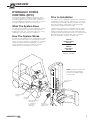
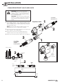
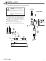
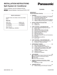
U SER MANUAL Hydraulic Force Control No. 6802876-R1 PL cascade corporation Cascade is a Registered Trademark of Cascade Corporation C ONTENTS OVERVIEW INSTALLATION Solenoid Operated Equalizer Valve and Hoses Non-Solenoid Intensify Valve and Hoses HFC Valve and Hoses Return-to-Tank & Optional Overdrive Valve Sensor Switch (if equipped) Disabling HFC System SETUP OPERATION TROUBLESHOOTING PARTS GLOSSARY i Page 1 2 2 3 4 5 6 7 8 10 11 13 18 6802876-R1 PL O VERVIEW HYDRAULIC FORCE CONTROL (HFC) This manual provides installation instructions, prior to operation, operation, troubleshooting and parts for Cascade Hydraulic Force Control (HFC) systems. If you need additional information or assistance, contact Cascade Corporation. Refer to the back cover. What The System Does The HFC system enables Cascade Paper Roll Clamps to automatically apply clamp force proportional to weight of the load. This system will reduce the chance of damage caused by excessive clamp force. How The System Works An initial no-slip starting pressure is applied to the load when it is first clamped. As the load is lifted, the HFC system increases clamp force and applies a consistent clamp force proportional to load weight. The hoist system provides pressure to the HFC to increase clamp pressure as hoist pressure increases. Prior to Installation The system can be calibrated to balance the clamp force relationship of clamp capacity and truck size. The truck HOIST pressure should be equal to or higher than clamp pressure to properly clamp paper. Total load weight equals paper weight plus clamp weight. Confirm that the truck size is compatible with the clamp capacity. Available maximum hoist pressure with load weight (combined maximum size load and weight of the clamp) should be determined in freelift. The hoist pressure determined needs to be within 10% of the clamping pressure required to clamp the heaviest load. HFC Kit (without switch) Part No. 6093682 HFC Kit (with switch) Part No. 6097470 (12 V) 6097471 (24V-48V) NOTE: Cascade recommends that component installation be done according to page number order. Sensor Switch (Page 6) Return-to-Tank (Page 5) HFC Valve (Page 4) Optional Overdrive Valve (Refer to Installation Instructions 6097260) 6802876-R1 PL Equalizer/ Intensify Valve (Page 2 & 3) AC1896.eps 1 I NSTALLATION EQUALIZER/INTENSIFY VALVE AND HOSES WARNING: Before removing hydraulic lines or components, relieve pressure in the hydraulic system. Turn truck off and open the truck auxiliary control valve(s) several times in both directions. WARNING: Follow all recommended safety practices including chaining the freelift mast to the mainlift crossmember when mast is raised. 1 Install adapter fittings to HFC, TRUCK and MAST ports To Auxiliary Valve Hoist Port Equalizer Valve on the equalizer valve. Install the equalizer valve in the hoist circuit between the hoist auxiliary valve and mast lowering control valve. NOTE: For trucks with a delivered flow volume of 18 GPM (68 L/min.) or less, install reducer fittings. 1 2 C HF 2 Install the hose from the hoist auxiliary valve HOIST port to the equalizer valve TRUCK port. K UC TR 3 Install a hose that connects the MAST port of the equalizer valve to the mast lowering control valve. 4 Inspect hoses for pinch points and secure as required. ST MA 3 1 To Lowering Control Valve and Mast Freelift Cylinder AC1897.eps C HF Mast Cylinders K UC TR 3 HFC Equalizer Valve ST MA TRUCK MAST Existing Lowering Control Valve Install reducer fittings, if required 2 Hoist Auxiliary Valve Truck Relief Valve Truck Hydraulic Pump Truck Tank AC1898.eps 2 6802876-R1 PL I NSTALLATION NON-SOLENOID INTENSIFY VALVE AND HOSES WARNING: Before removing hydraulic lines or components, relieve pressure in the hydraulic system. Turn truck off and open the truck auxiliary control valve(s) several times in both directions. To Lowering Control Valve Intensify Valve WARNING: Follow all recommended safety practices including chaining the freelift mast to the mainlift crossmember when mast is raised. 3 1 Install adapter fittings to HFC, TRUCK, and MAST ports. If IN and OUT ports are not plugged, install metal plugs. Install the intensify valve in the hoist circuit between the hoist auxiliary valve and mast lowering control valve. 2 Install the hose from the hoist auxiliary valve HOIST port to the intensify valve TRUCK port. K 1 3 MAST OUT HFC Existing Lowering Control Valve IN IN IN MAST HFC UC 1 Mast Cylinders TR 4 Inspect hoses for pinch points and secure as required. Install plugs TR intensify valve to the mast lowering control valve. OUT OUT 3 Install a hose that connects the MAST port of the 2 Intensify Valve TRUCK 2 Hoist Auxiliary Valve AC1873.eps To Auxiliary Valve Hoist Port Truck Relief Valve Truck Hydraulic Pump Truck Tank AC1735.eps 6802876-R1 PL 3 I NSTALLATION HFC VALVE AND HOSES HFC Valve 1 Install adapter fittings to T, H, CL1, CL2, OP1 and OP2 ports on the HFC valve. 5 2 Locate and install the HFC valve on the truck cowl using 5/16 in. (8 mm) capscrews. Watch for clearance when the mast is tilted back. The HFC valve cartridges have adjustment screws that will need to be easily accessed. 6 3 Connect a No. 6 (minimum) hose from the truck auxiliary clamp circuit CLAMP port to the CL1 port of the HFC valve. 1 4 Connect a No. 6 (minimum) hose from the truck auxiliary the HFC valve to the attachment revolving connection CLAMP port supply circuit. O V P 1 5 Connect a No. 6 (minimum) hose from the CL2 port of 2 C L2 valve clamp circuit OPEN port to the OP1 port of the HFC valve. 2 Hoist Line Pressure Gauge Port 6 Connect a No. 6 (minimum) hose from the OP2 port of 1 7 the HFC valve to the attachment revolving connection OPEN port supply circuit. 7 Connect a No. 6 (minimum) hose from the H port of the HFC valve to the HFC port of the equalizer valve. 8 Inspect hoses for pinch points and secure as required. 1 4 AC1768.eps 6 Mast Cylinders 3 Revolving Connection 5 OP2 CL2 HFC Equalizer Valve HFC Valve TRUCK H OP1 CL1 T MAST 7 4 Existing Lowering Control Valve Hoist Auxiliary Valve 3 Clamp Auxiliary Valve Truck Relief Valve Truck Hydraulic Pump Truck Tank AC1747.eps 4 6802876-R1 PL I NSTALLATION RETURN-TO-TANK & OPTIONAL OVERDRIVE VALVE 1 Install a return-to-tank fitting in the tank line. Lube hose ends and fitting for easy assembly. For complete installation procedure, refer to Installation Instructions 211744. Cascade Low Pressure Return Line Adapter Kits are as follows: Tank Hose ID Single Line Adapter Kit Dual Line Adapter Kit .75 in. (19 mm) 1.00 in. (25 mm) 1.25 in. (31 mm) 1.50 in. (38 mm) 214062 211745 214066 6037507 6049380 6049381 6049382 6049383 1 Returnto-Tank Line Return-to-Tank Fitting (Single shown) Hose to HFC Valve NOTE: For trucks with pressurized return-to-tank lines, the hydraulic tank filler cap must be opened to relieve trapped pressure. AC0226.eps 2 No Overdrive Valve – Connect the T port on the bottom of the HFC Valve to the truck tank line fitting. Overdrive Valve – Connect the overdrive valve T IN port with the HFC valve T port. Connect a hose from the overdrive valve T OUT port to the truck tank line fitting. Refer to installation instructions 6097260 for additional information. 2 P O V 1 C L2 HFC Valve CAUTION: If the overdrive valve is not directly installed to the HFC valve T port, a high pressure hose must be used. High pressure hose must be rated for 2300 psi (160 bar) working pressure. 3 Inspect hose for pinch points and secure as required. Revolving Connection Optional Overdrive Valve T IN OP2 CL2 HFC Valve H OP1 CL1 T Hoist Auxiliary Valve To Equalizer Valve To Equalizer Valve Clamp Auxiliary Valve Tank Hose Optional Overdrive Valve 2 1 Truck Relief Valve Truck Hydraulic Pump Tank Hose AC1766.eps Truck Tank AC1767.eps 6802876-R1 PL 5 I NSTALLATION SENSOR SWITCH (IF EQUIPPED) 1 Determine locations to mount the sensor switch on a NOTE: When installing on electric trucks with regenerative breaking, voltage filter 6061953 must be installed. Failure to install voltage filter can cause damage to electrical components. fixed location on the mast and the bracket with spring wire (if needed) on a moving member on the mast. The sensor switch will signal the mast transition from freelift to mainlift. The provided mounting bracket can be used or modified to aid with mounting the sensor switch. Moving member on mast CAUTION: Consult the LIft Truck OEM for proper + power source connection. 2 Connect the harness solenoid connector to the solenoid coil. 3 Connect the harness sensor switch connector to the Spring Wire with Bracket (if needed) sensor switch. 4 Connect the harness cable ends to the components shown. 12V Systems – Connect the fused positive wire from the cable harness to a switched power source and the ground wire to a chassis ground. Sensor Switch Fixed location on mast (additional bracket shown) 24V–48V Systems – Connect the fused positive wire from the cable harness to a DC-to-DC converter positive output wire and the ground wire to the converter negative output wire. Connect a 24V–48V switched power source to the converter fused positive input wire and connect the converter input ground wire to a chassis ground. AC1748.eps NOTE: For troubleshooting the wire harness, verify that the sensor switch, solenoid and relay are working properly. Check the LEDs on the sensor switch and solenoid. When the mast is in freelift, the LEDs will illuminate and when in mainlift, the LEDs will be off. Check current flow in and out of relay. Sensor Switch 2 OR .5 in. (12 mm) Moving Member (bracket with spring not used) Solenoid Relay .15 in. (4 mm) 30 85 86 87a Sensor Switch 87 3 4 Voltage Filter (24–48V systems only) AC1749.eps Fixed Member OR Cylinder Fuse Ground DC to DC Converter (24V–48V systems only) Switched Truck Battery Solenoid LED Truck Fuse Block Ground Switch LED AC1812.eps 6 6802876-R1 PL I NSTALLATION DISABLING HFC SYSTEM V5 To temporarily disable the HFC features, perform the following steps: NON-Solenoid INTENSIFY valve 1 Turn V1 inward (CW) or until desired clamp pressure is reached. The maximum pressure that the cartridge is capable of handling is 3000 psi (207 bar). HFC UC 4 The truck attachment will now operate in the standard K mode. TR load, turn V5 all the way out (CCW). IN MAST OUT 2 Turn V4 all the way out (CCW). 3 OPTIONAL: If the hoist capacity is affected by lifting a AC1738.eps NOTE: To enable HFC features refer to Prior To Operation Section. HFC valve V1 C HF K UC TR V5 ST MA AC1623.ai Solenoid OPERATED Equalizer valve AC1899.eps V4 6802876-R1 PL 7 S ETUP CARTRIDGE ADJUSTMENT CARTRIDGE FUNCTION SUMMARY Starting Pressure (V1) – Sets starting pressure. Final Pressure (V2) – Adjusts clamping pressure after hoisting. Must be adjusted after all other cartridges are set. Static Hoist Pressure (V3) – Closes connection from hoist line to clamp line. Freelift Pressure (V4) – Limits maximum clamping pressure. Must not be set lower than pressure needed to handle maximum roll. RC3288.ai Mainlift Pressure (V5) – Increases freelift hoisting pressure. Balances freelift and mainlift hoisting pressure and make pressure available to clamping circuit. IMPORTANT: Check that V2 is completely turned out (counterclockwise) before adjustment process. 1 Install the pressure gauge (Cascade Pressure Test Kit 6034612) in the long arm clamp cylinder gauge port. 2 Adjust the Starting Pressure (V1) cartridge so that a light load is not damaged or over clamped and the heaviest load does not slip upon hoisting. No Stand Zone 12 ft. (4 m) dia. Adjusts clamping pressure after hoisting. Adjust this cartridge last. V1 Starting Pressure Sets starting pressure. Must be higher then V3. Final Pressure V2 NOTE: For attachments that are retrofitted from three position relief to HFC system and lowest pressure is known, use the lowest pressure as starting pressure. 3 To prevent carriage/attachment from lowering during arm closing, adjust the Static Hoist Pressure (V3) cartridge. This pressure must be less than the Starting Pressure (V1). AC1578.eps • If the maximum weight load slips when hoisting, reduce V3 by turning counterclockwise (CCW). • If the carriage lowers when closing the arms of the clamp, increase V3 by turning clockwise (CW). 4 To limit the maximum clamp pressure (V4), fully close arms without a load and hoist to maximum lift. Fully extend the mast and hold the lever for 2 seconds. Lower the mast without unclamping and check the pressure. If the pressure exceeds the desired maximum clamp pressure for the heaviest load, turn the cartridge (V4) CCW to decrease the maximum pressure. 8 V3 Static Hoist Pressure Closes connection from hoist line to clamp line. Must be lower then V1. V4 Maximum Clamp Pressure Limit maximum clamping pressure. 6802876-R1 PL S ETUP CARTRIDGE ADJUSTMENT (CONTINUED) 5 To equalize the hoist pressure between freelift and Increases freelift hoisting pressure mainlift, clamp an average load and hoist off the ground about 1 ft (30 cm) (freelift). Record the pressure. With the same load at a higher position (mainlift), set load down in mainlift position. Reclamp the load, hoist the load and lower to the ground without unclamping. Record the pressure. V5 NON-Solenoid INTENSIFY valve OUT • If pressure is within 150 psi (10.5 bar), no adjustment is required. UC HFC TR • If freelift pressure is higher than the mainlift pressure, decrease V5 by turning CCW to equalize pressure. IN MAST • If mainlift pressure is higher than the freelift pressure, increase V5 by turning CW to equalize pressure. K 6 For non-freelift mast large trucks with small attachments, AC1738.eps clamp pressure may need to be increased. If equipped, the solenoid should be powered at all times by mounting the sensor switch in a location that will always switch on a ferrous object. Clamp a roll and hoist. Note the clamp cylinder pressure. • If the pressure is less than the desired clamp pressure, increase the pressure by turning V5 in CW to match the desired clamp pressure. NOTE: For freelift mast large trucks with small attachments and adequate clamp pressure can not be achieved with the standard valve, a special equalizer valve may be required. Contact Cascade for more detail. 7 To adjust the Final Pressure (V2), clamp a load. Hoist the load. Use the chart below to record the initial clamp pressure. If the pressure is too high for the heaviest load, turn the cartridge CW to reduce the adjusted clamp pressure. Record the adjusted clamp pressure. ROLL WEIGHT INITIAL CLAMP PRESSURE ● ADJUSTED CLAMP PRESSURE ● Increases freelift hoisting pressure C HF K UC TR V5 ST MA Solenoid operated Equalizer valve AC1899.eps #1 #2 #3 #4 #5 ●Read from long arm clamp cylinder gauge port 6802876-R1 PL 9 O PERATION Auxiliary Valve Functions Hoist Down WARNING: Truck control handle and attachment function activation shown here conforms to ASME/ANSI B56.1 recommended practices. Failure to follow these practices may lead to serious bodily injury or property damage. End user, dealer and OEMs should review any deviation from the practices for safe operation. Tilt Forward A C B D GA0005.eps Hoist Up Tilt Back ROTATE (Driver’s view) A B Long Arm Counterclockwise (CCW) Clockwise (CW) (vertical & horizontal positions only) C D Release Short Arm Clamp (45-degree position only) B C D D C RC0030.eps The HFC system works fundamentally the same as a normal lift truck system when used with a paper roll clamp. Use the following techniques when clamping loads: 1 Clamp arms firmly on the roll. build starting clamp pressure. Hold for 1 second to 2 Lift the load. Clamp pressure will automatically increase according to load weight. 3 If feathering is used to reduce clamp force on light loads, use the same process with HFC. However, it is recommended to use the techniques above for all loads unless absolutely necessary. CAUTION: Develop adequate clamp force to hold the load when feathering. 10 Close A D C Open RC0031.eps 4 Operation for a split arm clamp with HFC is the same as a solid arm clamp except for the following: • HFC should be used with the Cascade full arm travel split arm circuit. Close the free arm fully when handling one roll with one split arm. Full clamp force develops after free arm bottoms. • When clamping a full height roll with both split arms, operate the clamp as a solid arm clamp. NOTE: HFC allows lower clamp starting pressures so that light loads can be handled without damage along with heavier loads. Slightly slower arm speed is normal. If roll diameters vary widely with very low starting pressures, the slower arm speed can be corrected with an optional arm overdrive system. Consult Cascade. 6802876-R1 PL T ROUBLESHOOTING CAUTION: Prior to troubleshooting, verify that clamp is working properly and check for defective check valves and cylinder seals. NOTE: When adjusting cartridges, turn in 1/2 turn increments. Problem Pad slips on load at start of lift Solution Possible Effect Increase (CW) V1, reclamp May over clamp light roll If pressure in clamp cylinder does not increase after lifting, decrease (CCW) V3 May cause unit to lower during clamping Decrease (CCW) V2, reclamp Load continues to slip after V2 has been decreased Increase (CW) V5 May over clamp after hoisting Load may not hoist (truck and clamp capacity may not be compatible, contact Cascade) May cause pads to slip at hoisting Pads crush load before hoisting Decrease (CCW) V1, reclamp Pads crush load after hoisting Increase (CW) V2, open and reclamp May cause load to slip If problem occurs during freelift, decrease (CCW) V5 May cause load to slip in freelift Decrease (CCW) V2, reclamp and hoist May over clamp load Load slips when lift truck hits floor bumps or dock plate 6802876-R1 PL May cause slower arm speed during clamping 11 T ROUBLESHOOTING Problem Solution Possible Effect of Solution Hoist cylinder will not lift with a high capacity load Decrease (CCW) V5 May cause mainlift and freelift to be unbalanced Hoist lowers while closing arms Increase (CW) V3 May not add pressure during hoisting Hoist speed is decreased Decrease (CCW) V5 May have more clamp pressure in mainlift than freelift. Available clamping pressure in freelift will be reduced. Clamped pressure is substantially higher in freelift over mainlift Install switch if not installed Improved accuracy Decrease (CCW) V5 Load may slip in freelift Clamped pressure is substantially lower in freelift over mainlift Increase (CW) V5 May over clamp in freelift Over clamps when mast runs out of travel Increase (CW) V4 May cut off needed clamp pressure on heavy loads Arm speed is too slow during clamping Increase (CW) V1 May over clamp light loads Light loads that require low starting pressure, install optional arm overdrive system Driver may overclamp load if button is not released in time or relief not properly set. 12 6802876-R1 PL P ARTS HYDRAULIC FORCE CONTROL KITS – LIMITED FREELIFT MAST 1 UC 4 TR HFC IN MAST OUT 2 K 3 5 AC1874.eps AC0926.eps Pressure Test Kit 6802876-R1 PL REF QTY PART NO. 1 2 3 4 5 1 1 2 1 2 1 6093682 6088041 6092596 6802656 6006014 6004478 6034612 DESCRIPTION HFC Kit – without switch HFC Valve Non-Solenoid Intensify Valve Fitting, 12-10 Test Point Fitting, 6-6 Test Point Fitting, 4-4 Pressure Test Kit 13 P ARTS HYDRAULIC FORCE CONTROL KITS – FULL FREELIFT MAST 5 6 4 3 9 2 0 1 ! Relay 8 7 Truck Fuse Block Truck Battery AC0926.eps Pressure Test Kit AC1901.eps REF QTY PART NO. PART NO. 6097470 1 2 3 4 5 6 7 8 9 10 11 1 1 2 1 1 1 1 1 1 1 2 1 6095957 ◆ 6097081 6802656 6095969 ◆ 6095839 ◆ 6088041 6017897 ◆ – – 6006014 6004478 6034612 6097471 217932 6095957 ● 6097081 6802656 6095969 ● 6095839 ● 6088041 6017897 ● 6061953 ● 6064659 ● 6006014 6004478 6034612 DESCRIPTION HFC Kit – 12V HFC Kit – 24V-48V Converter and Filter Kit ■ Wire Harness Solenoid Operated Equalizer Valve Fitting, 12-10 Switch Assembly Switch Mounting Bracket HFC Valve Fuse - 5 amp Voltage Converter, 24-48V➞12V Voltage Filter Test Point Fitting, 6-6 Test Point Fitting, 4-4 Pressure Test Kit ■ Includes items 7 & 8. ◆ Included in Switch Group 6097464 ● Included in Switch Group 6097465 14 6802876-R1 PL P ARTS EQUALIZER & INTENSIFY VALVES Non-Solenoid Intensify Valve 2 7 4 1 REF 3 1 2 3 4 5 6 7 4 5 AC1875.eps QTY PART NO. 1 1 1 2 1 1 2 6092596 6092590 611293 604511 601377 6093794 6092647 2646 QTY PART NO. 1 1 1 1 1 1 1 6097081 6097065 601676 611293 6056977 6014287 6093794 6092647 DESCRIPTION Non-Solenoid Intensify Valve Valve Body Fitting, 12-12 Fitting, 6-6 Fitting, 8-8 Fitting, 12-12 Relief Valve Cartridge Fitting, 8 6 Solenoid Equalizer Valve 2 3 1 4 5 REF 4 AC1779.eps 6802876-R1 PL 7 6 1 2 3 4 5 6 7 DESCRIPTION Equalizer Valve Valve Body Fitting, 6-6 Fitting, 12-12 Solenoid Valve Coil - 12V Fitting, 12-12 Relief Valve Cartridge 15 P ARTS SENSOR SWITCH 2 1 2 AC1724.eps REF 1 2 16 QTY PART NO. 1 1 6095969 6091430 6092966 DESCRIPTION Switch Assembly Bracket Switch 6802876-R1 PL P ARTS HFC VALVE @ !# 0! 2 AC1824.eps 1 % ^ 89 3 $ REF 2 6 7 5 4 QTY PART NO. DESCRIPTION 1 2 3 4 1 5 1 1 6088041 6088042 601377 604511 6091000 HFC Valve ■ Valve Body Fittings, 8-8 Fitting, 6-6 Pressure Sequence Valve Cartridge 5 6 7 8 9 10 11 12 13 14 15 16 1 1 2 1 1 1 2 1 1 1 1 1 6090999 220865 609234 210379 6024964 661676 661312 6086327 6098001 604510 6054498 663694 Pressure Sequence Valve Cartridge Shuttle Valve Fitting, 4 PO Check Valve Cartridge Seal Kit Relief Valve Cartridge Seal Kit Directional Valve Cartridge Relief Valve Cartridge Fitting, 6 Orifice .020 Fitting, 3 ■ Refer to Glossary for flow requirements 6802876-R1 PL 17 G LOSSARY Clamp Pressure – Pressure set to clamp a load. Final Pressure (V2) – The final HFC adjusted clamp pressure applied when the load is hoisted. Freelift Pressure (V5) – Pressure in the hoist line when the mast is in freelift state. Mainlift Pressure (V5) – Pressure in the hoist line when the mast has extended above freelift. Maximum Clamp Pressure (V4) – The maximum pressure set to clamp a load. Overdrive System – A system to aid with increasing arm speed and allows an attachment to have higher clamping pressure when breaking out rolls. Starting Pressure (V1) – The minimum clamp pressure that will be applied, even on light loads. Static Hoist Pressure (V3) – The hoist pressure to achieve prior to hoisting. Total Load Weight – The sum of the paper roll weight and clamp weight. 18 6802876-R1 PL BLANK Do you have questions you need answered right now? Call your nearest Cascade Service Department. Visit us online at www.cascorp.com Zijn er vragen waarop u direct een antwoord nodig hebt? Neem dan contact op met uwdichtstbijzijnde serviceafdeling van Cascade. Of ga naar www.cascorp.com Haben Sie Fragen, für die Sie sofort eine Antwort benötigen? Wenden Sie sich anIhren nächsten Cascade-Kundendienst. Besuchen Sie uns online: www.cascorp.com En cas de questions urgentes, contacter leservice d’entretien Cascade le plus proche. Visiter le site Web www.cascorp.com. Per domande urgenti contattare l’Ufficio Assistenza Cascade più vicino. Visitate il nostro sito all’indirizzo www.cascorp.com ¿Tiene alguna consulta que deba ser respondida de inmediato? Llame por teléfonoal servicio técnico de Cascade más cercano. Visítenos en www.cascorp.com AMERICAS Cascade Corporation U.S. Headquarters 2201 NE 201st Fairview, OR 97024-9718 Tel: 800-CASCADE (227-2233) Fax: 888-329-8207 Cascade do Brasil Rua João Guerra, 134 Macuco, Santos - SP Brasil 11015-130 Tel: 55-13-2105-8800 Fax: 55-13-2105-8899 Cascade Canada Inc. 5570 Timberlea Blvd. Mississauga, Ontario Canada L4W-4M6 Tel: 905-629-7777 Fax: 905-629-7785 EUROPE-AFRICA Cascade Italia S.R.L. European Headquarters Via Dell’Artigianato 1 37050 Vago di Lavagno (VR) Italy Tel: 39-045-8989111 Fax: 39-045-8989160 Cascade (Africa) Pty. Ltd. PO Box 625, Isando 1600 60A Steel Road Sparton, Kempton Park South Africa Tel: 27-11-975-9240 Fax: 27-11-394-1147 ASIA-PACIFIC Cascade Japan Ltd. 2-23, 2-Chome, Kukuchi Nishimachi Amagasaki, Hyogo Japan, 661-0978 Tel: 81-6-6420-9771 Fax: 81-6-6420-9777 Cascade Korea 121B 9L Namdong Ind. Complex, 691-8 Gojan-Dong Namdong-Ku Inchon, Korea Tel: +82-32-821-2051 Fax: +82-32-821-2055 Cascade-Xiamen No. 668 Yangguang Rd. Xinyang Industrial Zone Haicang, Xiamen City Fujian Province P.R. China 361026 Tel: 86-592-651-2500 Fax: 86-592-651-2571 Cascade Australia Pty. Ltd. 1445 Ipswich Road Rocklea, QLD 4107 Australia Tel: 1-800-227-223 Fax: +61 7 3373-7333 Cascade New Zealand 15 Ra Ora Drive East Tamaki, Auckland New Zealand Tel: +64-9-273-9136 Fax: +64-9-273-9137 Sunstream Industries Pte. Ltd. 18 Tuas South Street 5 Singapore 637796 Tel: +65-6795-7555 Fax: +65-6863-1368 Cascade India Material Handling Private Limited No 34, Global Trade Centre 1/1 Rambaugh Colony Lal Bahadur Shastri Road, Navi Peth, Pune 411 030 (Maharashtra) India Phone: +91 020 2432 5490 Fax: +91 020 2433 0881 c © Cascade Corporation 2009 11-2009 No. 6802876-R1 PL