1
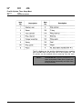
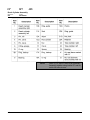
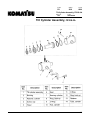
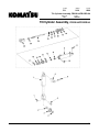
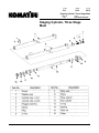
F-code
Section
C-code
PS
S6.5
6610
Staging Cylinder, Three Stage Mast
Version no
001
T-code
395/396/397/398/399
Staging Cylinder, Three Stage
Mast
© Komatsu Forklift U.S.A., Inc.
Master Service Manual
2002-01-15
473
F-code
Section
C-code
PS
S6.5
6610
Staging Cylinder, Three Stage Mast
Version no
T-code
001
395/396/397/398/399
1. Bearing Removal
1. Park the truck on a level surface and apply the
brake.
2. Fully extend the cylinders to inspect rod (12) for
gouges or pits. If gouges or pits are detected,
remove cylinder for repair.
!
DANGER Securely block columns to prevent
lowering. If not blocked, unexpected
movement could occur resulting in personal
injury or death.
3. Lift mast so inner column is raised approximately
12 inches (305 mm). Securely block mast.
4. Remove bolts from top end of staging cylinder
rods. Lower cylinder rods hydraulically.
5. Turn key switch to OFF and disconnect battery
connector from the truck.
! WARNING
Compressed air used for cleaning MUST
be reduced to less than 30 psi (205 kPa)
and then only with effective chip guarding
and personal protective equipment.
6. Clean the exterior of the lift cylinder.
474
Master Service Manual
2002-01-15
F-code
Section
C-code
PS
S6.5
5000
Staging Cylinder, Three Stage Mast
Version no
001
T-code
395/396/397/398/399
2. Disassembly
1. Remove bearing (14) from the cylinder tube.
2. Remove and discard rod wiper (16), seal (15),
wear ring (9) and O ring (13) from the bearing (14).
Discard seal (15). Use care NOT to damage the
inside of the bearing.
3. Assembly
1. Install new bearing (14), seal (15), wear ring (9), O
ring (13) and rod wiper (16).
2. The “lip” of the wiper must face outward.
3. It is not necessary to replace wear ring (9), unless
the cylinder was removed for rod repair.
4. Installation
1. Install bearing in the cylinder tube.
2. Raise cylinder rods hydraulically.
3. Install bolts in the top end of the staging cylinder.
4. Connect battery connector to the truck.
5. Test for proper operation.
© Komatsu Forklift U.S.A., Inc.
Master Service Manual
2002-01-15
475
F-code
Section
C-code
PS
S6.6
6620
Freelift Cylinder, Three Stage Mast
Version no
001
T-code
395/396/397/398/399
Freelift Cylinder, Three Stage
Mast
© Komatsu Forklift U.S.A., Inc.
Master Service Manual
2000-08-04
477
F-code
Section
C-code
PS
S6.6
6620
Freelift Cylinder, Three Stage Mast
Version no
T-code
001
395/396/397/398/399
The lift cylinders are the positive displacement type, meaning
there are NO seals on the lower end of the cylinder rod. The
lift cylinder can be resealed without removing from the truck.
NOTE!
478
CLEANLINESS! Perform procedures in a
clean environment. Make sure all parts are
cleaned before disassembly and kept clean
during assembly.
Master Service Manual
2000-08-04
F-code
Section
C-code
PS
S6.6
6620
Freelift Cylinder, Three Stage Mast
Version no
001
T-code
395/396/397/398/399
1. Removal
1. Park the truck on a level surface and apply the
brake.
2. Fully extend cylinder to inspect rod (9) for gouges
or pits. If gouges or pits are detected, cylinder must
be removed for repair.
!
DANGER Securely block columns to prevent
lowering. If not blocked, unexpected
movement could occur resulting in personal
injury or death.
3. Lift carriage/reach and securely block.
4. Lower cylinder so chains, hoses, and electric
cables are loose.
5. Turn key switch to OFF and disconnect battery
connector from the truck.
6. Remove chains, hoses, and electric cables from
the crosshead.
7. Remove crosshead from cylinder rod.
! WARNING
Compressed air used for cleaning MUST
be reduced to less than 30 psi (205 kPa)
and then only with effective chip guarding
and personal protective equipment.
8. Clean the exterior of the lift cylinder.
© Komatsu Forklift U.S.A., Inc.
Master Service Manual
2000-08-04
479
F-code
Section
C-code
PS
S6.6
6620
Freelift Cylinder, Three Stage Mast
Version no
T-code
001
395/396/397/398/399
2. Disassembly
1. Remove bearing (12) from the cylinder tube (3).
2. Remove and discard seal (14), back-up ring (11),
O ring (10), rod wiper (15) and ring guide (13) from
bearing (12). Use care NOT to damage the inside
of the bearing (12).
3. Assembly
1. Install new back-up ring (11), O ring (10), seal (14)
rod wiper (15) and guide ring (13).
2. The “lip” of the wiper must face outward.
4. Installation
1. Install crosshead, chains, hoses and electric
cables.
2. Connect battery connector to the truck.
3. Test for proper operation.
480
Master Service Manual
2000-08-04
F-code
PS
Version no
002
Section
C-code
S6.7
6650
Reach Cylinder Assembly
T-code
395/396/397
Reach Cylinder Assembly
© Komatsu Forklift U.S.A., Inc.
Master Service Manual
2000-08-04
481
F-code
Section
C-code
PS
S6.7
6650
Reach Cylinder Assembly
Version no
T-code
002
395/396/397
NOTE!
482
Items 13, 19, and 21 come as an assembly.
Assembly together using Loctite 277 and let
set for 24 hours to cure.
Master Service Manual
2000-08-04
F-code
PS
Version no
002
Section
C-code
S6.7
6650
Reach Cylinder Assembly
T-code
395/396/397
1. Removal
1. Park the truck on a level surface and apply the
brake.
2. Extend the reach about 1/2-3/4 of the total reach.
3. Block and chain the reach mechanism to prevent
movement of the reach mechanism.
4. Relieve pressure on the reach cylinders.
5. Remove hoses from the reach cylinder.
6. Remove roll pins (3). Remove front mounting pins
(4).
7. Raise reach assembly above full freelift. Remove
roll pins (3). Remove rear cylinder mounting pins
(5).
8. Remove reach cylinder from truck.
9. Turn key switch to OFF. Disconnect battery
connector from the truck.
© Komatsu Forklift U.S.A., Inc.
Master Service Manual
2000-08-04
483
F-code
Section
C-code
PS
S6.7
6650
Reach Cylinder Assembly
Version no
T-code
002
395/396/397
2. Disassembly
! WARNING
Compressed air used for cleaning MUST
be reduced to less than 30 psi (206 kPa),
and then only with effective chip-guarding
and personal protective equipment.
NOTE!
CLEANLINESS! Perform procedures in a
clean environment. Make sure all parts are
cleaned before disassembly and kept clean
during assembly.
1. Before disassembly, clean exterior of the reach
cylinder in a cleaning solution to remove all
contamination.
2. Be sure all hydraulic fluid has been removed from
the cylinder. Stroking the piston rod will help force
fluid out.
3. Put base end of cylinder in a vise equipped with
soft jaws.
4. Remove bearing retainer (22) and bearing (9) by
rotating bearing with a spanner wrench from
cylinder tube (23 or 24).
5. Remove bearing assembly, seal (11), rings (8) and
(17), and cylinder assembly consisting of the rod
(13), piston (19) and lock nut (21). Discard seal
(11).
6. Remove and discard rod wiper (12).
7. Inspect mounting bearing (25) located at base end
of the cylinders. Do not remove bearing unless
found to be unfit for further service.
484
Master Service Manual
2000-08-04
F-code
PS
Version no
002
Section
C-code
S6.7
6650
Reach Cylinder Assembly
T-code
395/396/397
3. Inspection
! WARNING
Compressed air used for cleaning MUST
be reduced to less than 30 psi (206 kPa),
and then only with effective chip-guarding
and personal protective equipment.
1. Carefully clean all parts in a cleaning solution and
position them on a clean work surface.
2. Check piston rod for damage. Look for gouges,
scratches, corrosion, or evidence of unusual wear.
Minor surface damage can be repaired by use of
fine abrasion cloth or stoning. Be extremely careful
to not remove chrome plating. Deeper damage will
require replacement of rod assembly. Make sure
the threads on the rod are free of damage.
3. Check cylinder bore for any damage. Parts with
deep gouges or pitted surfaces will require
replacement.
4. Check threaded section of cylinder tube to be sure
threads have not been damaged.
© Komatsu Forklift U.S.A., Inc.
Master Service Manual
2000-08-04
485
F-code
Section
C-code
PS
S6.7
6650
Reach Cylinder Assembly
Version no
T-code
002
395/396/397
4. Assembly
1. Install new O ring (7), back-up ring (8), ring guide
(10), seal (11), and rod wiper (12) in bearing
assembly (9). The “lip” of the wiper must face
outward.
2. Install new ring guide (20), back-up rings (17) and
(8) on piston (19).
3. Apply clean hydraulic fluid to rod cylinder (13).
Coat inside of cylinder tube and bearing assembly
with clean fluid.
4. Carefully slide spacer (16) (if used) and bearing
assembly (9) onto cylinder rod. Be sure rod end
does not cut or nick wiper upon installation.
5. Install cylinder assembly consisting of the rod (13),
piston (19) and lock nut (21) into cylinder tube (23
or 24). Be careful not to nick or cut piston seals on
the edge of cylinder tube or when sliding over
groove within tube. Torque cylinder piston lock nut
(21) to 47.94 ft-lb (65 N•m).
6. Install bearing assembly into cylinder tube. Use
care not to nick or cut seals upon installation.
7. Install retainer (22).
8. Check installation by making sure piston rod
assembly moves smoothly within tube assembly
without binding.
9. Install bearing (25).
486
Master Service Manual
2000-08-04
F-code
PS
Section
C-code
S6.7
6650
Reach Cylinder Assembly
Version no
002
T-code
395/396/397
5. Installation
1. Connect battery connector to the truck. Turn key
switch to ON.
2. Raise reach to full freelift height. Install reach
cylinder rear cylinder mounting pins (5). Secure
mounting pins with roll pins (3).
3. Lower reach assembly. Install reach cylinder front
mounting pins (4). Secure mounting pins with roll
pins (3).
4. Connect correct hydraulic hoses to reach cylinders.
5. Remove blocking and chains.
6. Fill hydraulic reservoir with new clean oil.
7. Operate reach to remove air from hydraulic hoses
and check operation of the whole hydraulic system.
! CAUTION
DO NOT use your hands to check for
hydraulic leakage. Use a piece of
cardboard or paper to search for leaks.
Escaping fluid under pressure can
penetrate the skin causing injury. Relieve
pressure before disconnecting hydraulic or
other lines. Tighten all connections before
applying pressure. Keep hands and body
away from pinholes and nozzles which
eject fluids under high pressure.
8. After running the hydraulic system, check and fill
hydraulic reservoir with new clean oil.
© Komatsu Forklift U.S.A., Inc.
Master Service Manual
2000-08-04
487
F-code
Section
C-code
PS
S6.8
6660
Tilt Cylinder Assembly, FR18S-2A
Version no
002
T-code
395/398/399
Tilt Cylinder Assembly, FR18S-2A
© Komatsu Forklift U.S.A., Inc.
Master Service Manual
2000-08-04
489
F-code
Section
C-code
PS
S6.8
6660
Tilt Cylinder Assembly, FR18S-2A
Version no
T-code
002
395/398/399
1. Removal
1. Park the truck on a level surface and apply the
brake.
2. Raise reach approximately 12 inches (305 mm)
and block so reach will not lower.
3. Pivot carriage upward and block to prevent
carriage/reach from lowering.
4. Turn key switch to OFF. Disconnect battery
connector from the truck.
5. Relieve pressure on tilt cylinder assembly (1).
6. Remove retainer (3) and cap screws (4) securing
cylinder to carriage/reach.
7. Remove hydraulic hoses from tilt cylinder
assembly (1).
8. Remove tilt cylinder assembly (1) from the truck.
490
Master Service Manual
2000-08-04
F-code
Section
C-code
PS
S6.8
6660
Tilt Cylinder Assembly, FR18S-2A
Version no
002
T-code
395/398/399
2. Disassembly
! WARNING
NOTE!
Compressed air used for cleaning MUST
be reduced to less than 30 psi (206 kPa),
and then only with effective chip-guarding
and personal protective equipment.
Perform procedures in a clean
environment. Make sure all parts are
cleaned before disassembly and kept clean
during assembly.
1. Before disassembly, clean exterior of tilt cylinder
(1) in a cleaning solution to remove all
contamination.
2. Be sure all hydraulic fluid has been removed from
cylinder. Stroking piston rod will help force fluid out.
3. Put trunnion of cylinder in a vise equipped with soft
jaws.
4. Remove bearing retainer (13) from cylinder tube.
5. Remove bearing assembly, seal (6), back-up ring
(8), cylinder rod (10) and piston seals.
6. Remove and discard all seals (6), O rings (9 and
11), back-up rings (8 and 12) and rod wiper (5).
7. Inspect mounting bushings (2) located at both ends
of cylinder. Do not remove bushings unless found
to be unfit for further service.
© Komatsu Forklift U.S.A., Inc.
Master Service Manual
2000-08-04
491
F-code
Section
C-code
PS
S6.8
6660
Tilt Cylinder Assembly, FR18S-2A
Version no
T-code
002
395/398/399
3. Inspection
! WARNING
Compressed air used for cleaning MUST
be reduced to less than 30 psi (206 kPa),
and then only with effective chip-guarding
and personal protective equipment.
1. Carefully clean all parts in a cleaning solution and
position on a clean work surface
2. Check cylinder rod (10) for damage. Look for
gouges, scratches, corrosion, or evidence of
unusual wear. Minor surface damage can be
repaired by the use of fine abrasion cloth or
stoning. Be extremely careful not to remove the
chrome plating. Deeper damage will require
replacement of piston rod assembly. Make sure
threads on rod are free of damage.
3. Check cylinder bore for any damage. Parts with
deep gouges or pitted surfaces will require
replacement.
4. Check threaded section of cylinder tube to be sure
threads have not been damaged.
492
Master Service Manual
2000-08-04
F-code
Section
C-code
PS
S6.8
6660
Tilt Cylinder Assembly, FR18S-2A
Version no
002
T-code
395/398/399
4. Assembly
1. Install new seals (6), O ring (9), backup ring (8),
and rod wiper (5) in bearing assembly. The “lip” of
the wiper must face outward.
2. Install new O ring (11) and back-up ring (12) on
cylinder rod (10).
3. Apply clean hydraulic fluid to cylinder rod
assembly. Coat the inside of the cylinder barrel and
bearing assembly with clean fluid.
4. Carefully slide bearing assembly on cylinder rod.
Be sure rod end does not cut or nick wiper (5) and
seal (6) upon installation.
5. Install rod into cylinder barrel. Be careful not to nick
or cut piston seals on the edge of cylinder barrel or
when sliding over groove within barrel.
6. Install bearing assembly into cylinder barrel. Use
care not to nick or cut seals upon installation.
7. Check installation by making sure cylinder rod
assembly moves fairly easy within barrel assembly
without binding.
8. Install bearing fastening ring and retainer.
© Komatsu Forklift U.S.A., Inc.
Master Service Manual
2000-08-04
493
F-code
Section
C-code
PS
S6.8
6660
Tilt Cylinder Assembly, FR18S-2A
Version no
T-code
002
395/398/399
5. Installation
1. Install cylinder on reach front frame.
2. Install retainer (3) and secure with four cap screws
(4).
3. Properly connect correct hydraulic hoses to front
and rear of tilt cylinder.
4. Remove blocking and chains.
5. Fill hydraulic reservoir with new clean oil.
6. Connect battery connector to the truck.
! WARNING
DO NOT use your hands to check for
hydraulic leakage. Use a piece of
cardboard or paper to search for leaks.
Escaping fluid under pressure can
penetrate the skin causing injury. Relieve
pressure before disconnecting hydraulic or
other lines. Tighten all connections before
applying pressure. Keep hands and body
away from pinholes and nozzles which
eject fluids under high pressure.
7. Operate tilt to remove air from hydraulic hoses and
check operation of whole hydraulic system.
8. After running the hydraulic system, check and fill
hydraulic reservoir with more new clean oil.
494
Master Service Manual
2000-08-04
F-code
Section
C-code
PS
S6.9
6660
Tilt Cylinder Assembly, FR23S-2A/FR15DR-2A
Version no
001
Tilt Cylinder Assembly,
© Komatsu Forklift U.S.A., Inc.
Master Service Manual
2000-08-04
T-code
396/397
FR23S-2A/FR15DR-2A
495
F-code
Section
C-code
PS
S6.9
6660
Tilt Cylinder Assembly, FR23S-2A/FR15DR-2A
Version no
T-code
001
396/397
496
Master Service Manual
2000-08-04
F-code
Section
C-code
PS
S6.9
6660
Tilt Cylinder Assembly, FR23S-2A/FR15DR-2A
Version no
001
T-code
396/397
1. Removal
1. Park the truck on a level surface and apply the
brake.
2. Raise reach approximately 12 inches (304 mm)
and block so reach will not lower.
3. Pivot carriage upward and block to prevent
carriage/reach from lowering.
4. Turn key switch to OFF and disconnect battery
connector from the truck.
5. Relieve pressure on tilt cylinder.
6. Remove hydraulic hoses from tilt cylinder and mark
their position.
7. Remove roll pin (6) and top mounting pin (5).
Remove tilt cylinder from truck.
8. Repeat procedure on other side of truck as
needed.
© Komatsu Forklift U.S.A., Inc.
Master Service Manual
2000-08-04
497
F-code
Section
C-code
PS
S6.9
6660
Tilt Cylinder Assembly, FR23S-2A/FR15DR-2A
Version no
T-code
001
396/397
2. Disassembly
! WARNING
NOTE!
Compressed air used for cleaning MUST
be reduced to less than 30 psi (206 kPa),
and then only with effective chip-guarding
and personal protective equipment.
CLEANLINESS! Perform procedures in a
clean environment. Make sure all parts are
cleaned before disassembly and kept clean
during assembly.
1. Before disassembly, clean exterior of tilt cylinder in
a cleaning solution to remove all contamination.
2. Be sure all hydraulic fluid has been removed from
cylinder. Stroking the piston rod will help force fluid
out.
3. Put base end of cylinder in a vise equipped with
soft jaws.
4. If necessary, remove roller bearing (3) at base of
cylinder rod (24). Remove roll pin (1) and slide
mounting pin (4) from clevis (26).
5. Remove retainer (10) by rotating gland with a
spanner wrench from cylinder tube (9).
6. Remove gland assembly, seals, rings, rod and
piston, and piston seals.
7. Remove and discard all seals and rod wiper (23).
8. Inspect mounting bearing (8) located at base end
of cylinder tube (9). Do not remove bearing unless
found to be unfit for further service.
498
Master Service Manual
2000-08-04
F-code
Section
C-code
PS
S6.9
6660
Tilt Cylinder Assembly, FR23S-2A/FR15DR-2A
Version no
001
T-code
396/397
3. Inspection
! WARNING
Compressed air used for cleaning MUST
be reduced to less than 30 psi (206 kPa),
and then only with effective chip-guarding
and personal protective equipment.
1. Carefully clean all parts in a cleaning solution and
position on a clean work surface
2. Check piston rod (24) for damage. Look for
gouges, scratches, corrosion or evidence of
unusual wear. Minor surface damage can be
repaired by use of fine abrasion cloth or stoning.
Be extremely careful not to remove the chrome
plating. Deeper damage will require replacement of
piston rod assembly. Make sure threads on rod are
free of damage.
3. Check cylinder bore for any damage. Parts with
deep gouges or pitted surfaces will require
replacement.
4
© Komatsu Forklift U.S.A., Inc.
Check threaded section of cylinder tube (9) to be
sure threads have not been damaged.
Master Service Manual
2000-08-04
499
F-code
Section
C-code
PS
S6.9
6660
Tilt Cylinder Assembly, FR23S-2A/FR15DR-2A
Version no
T-code
001
396/397
4. Assembly
1. Install new guide ring (21), seal (22) and rod wiper
(23) in gland assembly. The “lip” of the wiper must
face outward.
2. Install new piston seals (15) and (17), guide ring
(13), and sealing ring (16) on piston (14).
3. Install piston (14) on rod (24).
4. Install nut (11) on cylinder rod (24). Torque cylinder
piston nut to 60-65 ft-lb (81-88 N•m).
5. Apply clean hydraulic fluid to piston rod assembly.
Coat inside of cylinder tube (9) and gland
assembly with clean fluid.
6. Carefully slide gland assembly onto piston cylinder
rod (24). Be sure rod end does not cut or nick wiper
(23) and seal (22) upon installation.
7. Install piston and rod into cylinder tube (9). Be
careful not to nick or cut piston seals on the edge
of cylinder tube or when sliding over groove within
tube.
8. Install gland assembly into cylinder tube (9). Use
care not to nick or cut seals are upon installation.
9. Install retainer (10).
10. Check installation by making sure piston rod
assembly moves fairly easy within tube assembly
without binding.
11. Install bearing (20).
12. If removed, install roller bearing and clevis
assembly.
500
Master Service Manual
2000-08-04
F-code
Section
C-code
PS
S6.9
6660
Tilt Cylinder Assembly, FR23S-2A/FR15DR-2A
Version no
001
T-code
396/397
5. Installation
1. Install tilt cylinder on carriage/reach front frame.
Secure with mounting pin (5) with roll pin (6).
2. Properly connect correct hydraulic hoses to the top
and bottom of tilt cylinder.
3. Remove blocking and chains.
4. Fill hydraulic reservoir with new clean oil.
5. Connect battery connector to the truck.
6. Operate tilt to remove air from hydraulic hoses and
check operation of the whole hydraulic system.
! WARNING
DO NOT use your hands to check for
hydraulic leakage. Use a piece of
cardboard or paper to search for leaks.
Escaping fluid under pressure can
penetrate the skin causing injury. Relieve
pressure before disconnecting hydraulic or
other lines. Tighten all connections before
applying pressure. Keep hands and body
away from pinholes and nozzles which
eject fluids under high pressure.
7. After running the hydraulic system, check and fill
hydraulic reservoir with new clean oil.
© Komatsu Forklift U.S.A., Inc.
Master Service Manual
2000-08-04
501