1
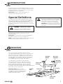
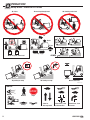
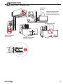
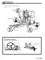
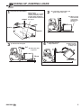
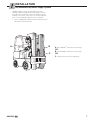
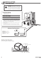
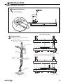
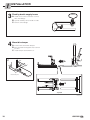
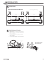
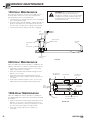
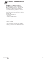
U SER MANUAL 10A Bin Dumper Number 6801202 EN cascade corporation Cascade is a Registered Trademark of Cascade Corporation C ONTENTS Page INTRODUCTION Special Definitions OPERATION Safety Rules Industrial Lift Trucks Handling Loads Daily Inspection Bin Dumper Operation – Auxiliary Valve Functions Picking Up, Dumping Loads Safe Operation and Maintenance OSHA Regulations INSTALLATION Recommended Hydraulic Supply Truck Requirements Attachment Installation PERIODIC MAINTENANCE 100-Hour Maintenance 500-Hour Maintenance 1000-Hour Maintenance 2000-Hour Maintenance i 1 1 2 3 4 4 5 6 6 7 8 9 12 12 12 13 6801202 EN I NTRODUCTION This manual is for the Cascade 10A Bin Dumper. Contents include an Operator's Guide, Installation Instructions and Periodic Maintenance. All specifications are shown in US and (Metric) units where applicable. IMPORTANT: All hoses, tubes and fittings on the attachments are SAE O-Ring Face Seal. Special Definitions The statements shown appear throughout this manual where special emphasis is required. Read all WARNINGS and CAUTIONS before proceeding with any work. Statements labeled IMPORTANT and NOTE are provided as additional information of special significance or to make the job easier. WARNING: Rated capacity of the truck/ attachment combination is a responsibility of the original truck manufacturer and may be less than shown on the attachment nameplate. Consult the truck nameplate. WARNING: Do not operate this attachment unless you are a trained and authorized lift truck driver. WARNING – A statement preceded by WARNING is information that should be acted upon to prevent bodily injury. A WARNING is always inside a ruled box. CAUTION – A statement preceded by CAUTION is information that should be acted upon to prevent machine damage. IMPORTANT – A statement preceded by IMPORTANT is information that possesses special significance. NOTE – A statement preceded by NOTE is information that is handy to know and may make the job easier. O PERATION This section contains operating instructions for the Cascade 10A Bin Dumper. It will help you avoid common errors which often cause damage to the equipment or product being handled. 10A Bin Dumpers are designed to handle agricultural and industrial bins of various sizes and capabilities. The backrest is manually adjustable to accommodate different bin heights and lengths. This information is intended to simplify operator understanding about effective and safe bin dumper use and operation. Read this information thoroughly before operating the attachment. Be sure you know and understand all operating procedures and safety precautions. If you have any questions or don’t understand a procedure, ask your supervisor. Emphasize Safety! Most accidents are caused by operator carelessness or misjudgment. You must watch for poorly maintained equipment and hazardous situations and correct them. Front Bin Stops Adjustable Backrest Bin Length Adjustment Bin Height Adjustment Upper Frame Assembly Fork Pin Frame Pivots BD0144.eps Lower Frame Assembly 6801202 EN 1 O PERATION Safety Rules – Industrial Lift Trucks No riders No reaching through mast No standing under load BD0145.eps Tilt With load Raise 8 cm No load P P Traveling empty Motor off, park, lower load RAMPS P No parking on ramp No turning on ramp Watch clearances BD0146.eps TRAFFIC STOP Observe Wet floors 2 Workers Stops Bumps Dips Slow for two-way traffic Sound horn, slow at intersection Sound horn, slow at corner 6801202 EN O PERATION Safety Rules – Handling Loads Adjust stops to top of bin. Load weight must not exceed combined truck/attachment capacity (see truck nameplate). No loads on top of bin. Limit truck movement with raised bin. BD0167.eps 6801202 EN Center bin prior to lifting, traveling or dumping. BD0147.eps No Stand Zone 4 m dia. 3 O PERATION Daily Inspection Check items each day. Report problems to your supervisor. See service manual for maintenance and repair procedures. Fasteners Hydraulic Leaks BD0148.eps Fork Pin Engagement Safety Decals Forks, Bin Stops Bin Dumper Operation – Auxiliary Valve Functions Hoist Down Tilt Forward A B GA0010.eps Hoist Up 4 Tilt Back B A Dumper Forward B Dumper Back BD0164.eps A 6801202 EN P 1 ICKING UP, DUMPING LOADS Verify bin fits attachment Adjust stops. Height: Allow up to 38 mm clearance with top of bin. Length: Allow maximum 6 mm clearance from front HEIGHT bin stops. 2 A) Level forks, drive forward, bin against upper bin stops B) Move control level forward 1 second to engage front bin stops A WIDTH LENGTH BD0150.eps BD0149.eps 3 4 A) Tilt back for transport 3-4° A) Level bin, raise for dump clearance B) Move control lever forward to dump load B) Raise bin clear of ground 10 cm Watch Clearance BD0151.eps BD0152.eps 6801202 EN 5 S AFE OPERATION AND MAINTENANCE Trucks and Attachments WARNING: When operating and maintaining industrial trucks equipped with attachments, you should pay particular attention to the following information. You should be familiar with this information for truck and attachment operation. Ask your employer for complete operation information. General Requirement Traveling Modifications and additions which affect capacity and safe operation shall not be performed by the customer or user without manufacturers prior written approval. Capacity, operation and maintenance instruction plates, tags or decals shall be changed accordingly. The driver shall be required to slow down and sound the horn at cross isles and other locations where vision is obstructed. If the load being carried obstructs forward view, the driver shall be required to travel with the load trailing. If the truck is equipped with front-end attachments other than factory installed attachments, the user shall request that the truck be marked to identify the attachments and show the appropriate weight of the truck and attachment combination at maximum elevation with load laterally centered. When ascending or descending grades in excess of 10 percent, loaded trucks shall be driven with the load upgrade. On all grades the load and load engaging means shall be tilted back if applicable, and raised only as far as necessary to clear the road surface. The user shall see that all nameplates and markings are in place and maintained in a legible condition. Loading Only stable or safely arranged loads shall be handled. Caution shall be exercised when handling off-center loads which cannot be centered. Only loads within the rated capacity of the truck shall be handled. The long or high (including multiple-tiered) loads which may affect capacity shall be adjusted. Trucks equipped with attachments shall be operated as partially loaded trucks when not handling a load. A load engaging means shall be placed under the load as far as possible; the mast shall be carefully tilted backward to stabilize the load. Extreme care shall be used when tilting the load forward or backward, particularly when high tiering. Tilting forward with load engaging means elevated shall be prohibited except to pick up a load. An elevated load shall not be tilted forward except when the load is in a deposit position over a rack or stack. When stacking or tiering, only enough backward tilt to stabilize the load shall be used. Safety Guards If the type of load presents a hazard, the user shall equip fork trucks with a vertical load backrest extension in accordance with the following. All new powered industrial trucks acquired and used by an employer after February 15, 1972 shall meet the design and construction requirements for powered industrial trucks established in the “American National Standard for Powered Industrial Trucks, Part II, ANSI B56.1”, except for vehicles intended primarily for earth moving or over-the-road hauling. Operator Training Only trained and authorized operators shall be permitted to operate a powered industrial truck. Methods shall be devised to train operators in the safe operation of powered industrial trucks. Truck Operations Trucks shall not be driven up to anyone standing in front of a bench or other fixed object. No person shall be allowed to stand or pass under the elevated portion of any truck, whether loaded or empty. Unauthorized personnel shall not be permitted to ride on powered industrial trucks. A safe place to ride shall be provided where riding of trucks is authorized. Maintenance of Industrial Trucks The employer shall prohibit arms or legs from being placed between the uprights of the mast or outside the running lines of the truck. When a powered industrial truck is left unattended, load engaging means shall be fully lowered, controls shall be neutralized, power shall be shut off and brakes set. Wheels shall be blocked if the truck is parked on an incline. A powered industrial truck is unattended when the operator is 7 meter or more away from the vehicle which remains in his view, or whenever the operator leaves the vehicle and it is not in his view. When the operator of an industrial truck is dismounted and within 7 meter of the truck still in his view, the load engaging means shall be fully lowered, controls neutralized and the brakes set to prevent movement. A safe distance shall be maintained from the edge of ramps or platforms while on any elevated dock or platform or freight car. Trucks shall not be used for opening or closing freight doors. A load backrest extension shall be used whenever necessary to minimize the possibility of the load or part of it from falling rearward. 6 Operation of the Truck If at any time a powered industrial truck is found to be in need of repair, defective, or in any way unsafe, the truck shall be taken out of service until it has been restored to safe operating condition. Any power-operated industrial truck not in safe operating condition shall be removed from service. All repairs shall be made by authorized personnel. All parts of any such industrial truck requiring replacement shall be replaced only by parts equivalent as to safety with those used in the original design. Industrial trucks shall not be altered so that the relative positions of the various parts are different from what they were when originally received from the manufacturer, nor shall they be altered either by the addition of extra parts not provided by the manufacturer or by the elimination of any parts. Additional counter-weighting of fork trucks shall not be done unless approved by the truck manufacturer. Industrial trucks shall be examined before being placed in service and shall not be placed in service if the examination shows any condition adversely affecting the safety of the vehicle. Such examinations shall be made at least daily. When industrial trucks are used on a round-the-clock basis, they shall be examined after each shift. Defects when found shall be immediately reported and corrected. 6801202 EN I NSTALLATION Recommended Hydraulic Supply Options 10A Bin Dumpers can be operated with any of the hydraulic supply arrangements shown below. Refer to Cascade Hose & Cable Reel Selection Guide, Part No. 212199, to select the correct hose reel for the mast and truck. Hose and fitting requirements are as follows: • Hoses and fittings for dump function should be at least No. 6 with 7 mm minimum ID. A B C A RH THINLINETM 2-Port Hose Reel Group OR B LH THINLINETM 2-Port Hose Reel Group OR C Single Internal Hose Reeving Group GA0033.eps 6801202 EN 7 I NSTALLATION Truck Requirements WARNING: Rated Capacity of the truck/ attachment combination is a responsibility of the original truck manufacturer and may be less than that shown on the attachment nameplate. Consult the truck nameplate. Truck Relief Setting 140 bar Recommended 160 bar Maximum Truck Flow Volume ➀ 10A Min. ➁ Recommended Max. ➂ 19 L/min. 26 L/min. 38 L/min. ➀ Cascade Bin Dumpers are compatible with SAE 10W petroleum base hydraulic fluid meeting Mil. Spec. MIL-0-5606 or MIL-02104B. Use of synthetic or aqueous base hydraulic fluid is not recommended. If fire resistant hydraulic fluid is required, special seals must be used. Contact Cascade. ➁ Flow less than recommended will result in slower than normal dumping speed. ➂ Flow greater than maximum can result in excessive heating, reduced system performance and short hydraulic system life. GA0421.eps Maximum Fork Dimensions W Width (W) – 145 mm T Thickness (T) – 50 mm Length (L) – 1100 mm L Auxiliary Valve Functions Check for compliance with ANSI Standards: Tilt Forward Hoist Down Dumper Forward GA0126.eps Hoist Up 8 Tilt Back Dumper Back 6801202 EN I NSTALLATION Attachment Installation 1 Prepare Attachment A Remove banding. B Disconnect fork pins. BD0153.eps B Fork Pin 2 Hose Reel (RH shown) Prepare Hoses A Determine hose lengths required for hydraulic supply. B Cut hoses to length, install end fittings or quick disconnect kits. Hose Terminal BD0154.eps Extend Retract Single Internal Hose Reeving (RH shown) Quick Disconnect Fittings Quick Disconnect Fittings Bin Dumper Valve BD0155.eps BD0156.eps 6801202 EN Extend Retract 9 I NSTALLATION 3 Flush hydraulic supply hoses A Install hoses to hose terminals. Connect with union fittings. B C Operate auxiliary valves for 30 seconds. Remove union fittings. GA0092.eps 4 Mount bin dumper A Position forks behind bin dumper. B Drive forward inserting forks into rear fork pockets. C Install fork pins behind fork heel. C A Install fork pins BD0158.eps B Top View BD0157.eps 10 6801202 EN I NSTALLATION 5 Connect Hoses Single Internal Hose Reeving (RH shown) BD0159.eps 6 Hose Reel (RH shown) BD0160.eps Cycle Attachment Function • With no load, cycle dumper forward and back several times. • With an empty bin, cycle dumper forward and back several times. • Check for operation in accordance with ITA (ISO) standards. • Check for leaks at fittings, valve and cylinders. Hoist Down Tilt Forward A Dumper Forward B Dumper Back A B B GA0010.eps Hoist Up Tilt Back BD0164.eps A 6801202 EN 11 P ERIODIC MAINTENANCE 100-Hour Maintenance Every time the lift truck is service or every 100 hours of truck operation, whichever comes first, complete the following maintenance on the attachment: • Check for loose or missing fasteners, worn or damaged hoses and hydraulic leaks. WARNING: After completing any service procedure, always test each function through five complete cycles. First test with no load, then test with a load to make sure the attachment operates correctly before returning it to the job. • Inspect front bin stops for damage. If front stops do not go all the way down, loosen the domed nut jam nuts. Turn the outer nut CW 1/4 turn. Tighten nuts and test. • Check that the fork pin detent locks when engaged. Lift Cylinder Bearing Upper Frame Assembly Front Bin Stops Lift Cylinder Cap Lift Cylinder BD0165.eps Lower Frame Bearing Side View 500-Hour Maintenance After each 500 hours of truck operation, in addition to the 100-hour maintenance, perform the following procedures. • Inspect tilt cylinder pivot pin retainers. If necessary tighten capscrews to 11–13 Nm. • Inspect the front bin stop rod and bushings for wear. Replace as necessary. Bin Stop Rod and Bushing • Inspect tilt frame pivot pin and bushings for wear. Replace as necessary. Tighten retainer capscrews to 11–13 Nm. Tilt Cylinders Tilt Adjuster Lock Nut • Verify that the tilt frame rotates to 135°. If necessary adjust locknut located underneath the attachment. Lower Frame Bearings Tilt Frame Pivot Pins 1000-Hour Maintenance After each 1000 hours of truck operation, in addition to the 100 and 500-hour maintenance, perform the following procedures. • Inspect lower frame and lift cylinder bearings for wear. Replace as necessary. If the bearing is worn to less than 2.5 mm thickness, replace the bearing set. Refer to service manual for replacement procedure. BD0166.eps Fork Pin Cylinder Rod Ends and Pivot Pin Retainers Bottom View • Inspect lift cylinder cap for wear. Replace as necessary. 12 6801202 EN P ERIODIC MAINTENANCE 2000-Hour Maintenance After 2000 hours of truck operation, in addition to the 100, 500 and 1000-hour maintenance, forks in use shall be inspected at intervals of not more than 12 months (for single shift operations) or whenever any defect or permanent deformation is detected. Severe applications will require more frequent inspection. Fork inspection shall be carried out by trained personnel to detect any damage that might impair safe use. Any fork that is defective shall be removed from service. Reference ANSI B56.1-2005. Inspect for the following defects: • Surface cracks • Straightness of blade and shank • Fork angle • Difference in height of fork tips • Positioning lock • Wear on fork blade and shank • Wear on fork hooks • Legibility of marking NOTE: Fork Safety Kit 3014162 contains wear calipers, inspection sheets and safety poster. Also available is fork hook & carriage wear gauge 209560 (Class II) and 209561 (Class III). 6801202 EN 13 Do you have questions you need answered right now? Call your nearest Cascade Service Department. Visit us online at www.cascorp.com Zijn er vragen waarop u direct een antwoord nodig hebt? Neem dan contact op met uwdichtstbijzijnde serviceafdeling van Cascade. Of ga naar www.cascorp.com Haben Sie Fragen, für die Sie sofort eine Antwort benötigen? Wenden Sie sich anIhren nächsten Cascade-Kundendienst. Besuchen Sie uns online: www.cascorp.com En cas de questions urgentes, contacter leservice d’entretien Cascade le plus proche. Visiter le site Web www.cascorp.com. Per domande urgenti contattare l’Ufficio Assistenza Cascade più vicino. Visitate il nostro sito all’indirizzo www.cascorp.com ¿Tiene alguna consulta que deba ser respondida de inmediato? Llame por teléfonoal servicio técnico de Cascade más cercano. Visítenos en www.cascorp.com AMERICAS Cascade Corporation U.S. Headquarters 2201 NE 201st Fairview, OR 97024-9718 Tel: 800-CASCADE (227-2233) Fax: 888-329-8207 Cascade Canada Inc. 5570 Timberlea Blvd. Mississauga, Ontario Canada L4W-4M6 Tel: 905-629-7777 Fax: 905-629-7785 Cascade do Brasil Rua João Guerra, 134 Macuco, Santos - SP Brasil 11015-130 Tel: 55-13-2105-8800 Fax: 55-13-2105-8899 EUROPE-AFRICA Cascade Italia S.R.L. European Headquarters Via Dell’Artigianato 1 37030 Vago di Lavagno (VR) Italy Tel: 39-045-8989111 Fax: 39-045-8989160 Cascade (Africa) Pty. Ltd. PO Box 625, Isando 1600 60A Steel Road Sparton, Kempton Park South Africa Tel: 27-11-975-9240 Fax: 27-11-394-1147 ASIA-PACIFIC Cascade Japan Ltd. 2-23, 2-Chome, Kukuchi Nishimachi Amagasaki, Hyogo Japan, 661-0978 Tel: 81-6-6420-9771 Fax: 81-6-6420-9777 Cascade Korea 121B 9L Namdong Ind. Complex, 691-8 Gojan-Dong Namdong-Ku Inchon, Korea Tel: +82-32-821-2051 Fax: +82-32-821-2055 Cascade-Xiamen No. 668 Yangguang Rd. Xinyang Industrial Zone Haicang, Xiamen City Fujian Province P.R. China 361026 Tel: 86-592-651-2500 Fax: 86-592-651-2571 Cascade Australia Pty. Ltd. 1445 Ipswich Road Rocklea, QLD 4107 Australia Tel: 1-800-227-223 Fax: +61 7 3373-7333 Cascade New Zealand 15 Ra Ora Drive East Tamaki, Auckland New Zealand Tel: +64-9-273-9136 Fax: +64-9-273-9137 Sunstream Industries Pte. Ltd. 18 Tuas South Street 5 Singapore 637796 Tel: +65-6795-7555 Fax: +65-6863-1368 Cascade India Material Handling Private Limited No 34, Global Trade Centre 1/1 Rambaugh Colony Lal Bahadur Shastri Road, Navi Peth, Pune 411 030 (Maharashtra) India Phone: +91 020 2432 5490 Fax: +91 020 2433 0881 c © Cascade Corporation 2009 11-2009 Part Number 6801202 EN