1
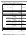
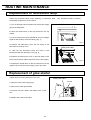
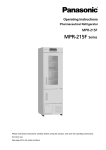
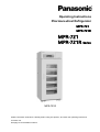
Operating Instructions
Pharmaceutical Refrigerator
MPR-721
MPR-721R
MPR-721
MPR-721R Series
MPR-721R
Please read these instructions carefully before using this product, and save this operating instructions
for future use.
See page 37 for all Model numbers.
CONTENTS
INTRODUCTION
P. 2
PRECAUTIONS FOR SAFE OPERATION
P. 3
ENVIRONMENTAL CONDITIONS
P. 7
REFRIGERATOR COMPONENTS
P. 8
Inside of front cover
P. 10
Control panel
P. 11
INSTALLATION SITE
P. 12
INSTALLATION
P. 13
START-UP OF UNIT
P. 14
STOCK OF CONTAINERS
P. 15
CHAMBER TEMPERATURE SETTING
P. 16
KEY LOCK FUNCTION
P. 16
ALARM TEMPERATURE SETTING
P. 17
SETTING OF DELAY OF DOOR ALARM
P. 18
SETTING OF RINGBACK OF ALARM BUZZER
P. 19
OPERATION CHECK AFTER RECOVERY
P. 19
DEFROST CYCLES
P. 20
REMOTE ALARM TERMINAL
P. 20
ALARMS & SAFETY FUNCTIONS
P. 21
ROUTINE MAINTENANCE
P. 22
Cleaning of cabinet
P. 22
Cleaning of evaporating tray
P. 22
Replacement of fluorescent lamp
P. 23
Replacement of glow starter
P. 23
TROUBLESHOOTING
P. 24
DISPOSAL OF UNIT
P. 25
OPTIONAL COMPONENTS
P. 30
Temperature recorder
P. 30
TEMPERATURE RECORDER (OPTION)
P. 31
Setting of MTR-0621LH
P. 31
Setting of MTR-G04A/MTR-G04C
P. 33
BATTERY MOUNTING BOX (OPTION)
P. 35
Setting of MPR-48B
P. 35
SPECIFICATIONS
P. 36
PERFORMANCE
P. 37
SAFETY CHECK SHEET
P. 38
1
INTRODUCTION
Read this operating instructions carefully before using the appliance and follow the instructions for
safety operation.
Our company never guarantee any safety if the appliance is used for any objects other than intended
use or used by any procedures other than those mentioned in this operating instructions.
Keep this operating instructions in an adequate place to refer to it as necessary.
The contents of the operating instructions will be subjected to change without notice due to the
improvement of performance or functions.
Contact our sales representative or agent if any page of the operating instructions is lost or page order
is incorrect.
Contact our sales representative or agent if any point in this operating instructions is unclear or if there
are any inaccuracies.
No part of this operating instructions may be reproduced in any form without the expressed written
permission of our company.
CAUTION
Our company guarantees the product under certain warranty conditions.
way shall be responsible for any loss of content or damage of content.
2
Our company in no
PRECAUTIONS FOR SAFE OPERATION
It is imperative that the user complies with this operating instructions
as it contains important safety advice.
Items and procedures are described so that you can use this unit correctly and safely.
If the precautions advised are followed, this will prevent possible injury to the user and
any other person.
Precautions are illustrated in the following way:
WARNING
Failure to observe WARNING signs could result in a hazard to personnel
possibly resulting in serious injury or death.
CAUTION
Failure to observe CAUTION signs could result in injury to personnel and
damage to the unit and associated property.
Symbol shows;
this symbol means caution.
this symbol means an action is prohibited.
this symbol means an instruction must be followed.
Be sure to keep this operating instructions in a place accessible to users of this unit.
< Label on the unit >
This mark is labeled on the cover in which the electrical components of high voltage
are enclosed to prevent the electric shock.
The cover should be removed by a qualified engineer or a service personnel only.
3
PRECAUTIONS FOR SAFE OPERATION
WARNING
Do not use the unit outdoors.
Current leakage or electric shock may result if the unit is exposed to
rain water.
Only qualified engineers or service personnel should install the unit.
The installation by
unqualified personnel may cause electric shock or fire.
Install the unit on a sturdy floor and take an adequate precaution to prevent the unit from
turning over.
If the floor is not strong enough or the installation site is not adequate, this may result
in injury from the unit falling or tipping over.
Never install the unit in a humid place or a place where it is likely to be splashed by water.
Deterioration of the insulation may result which could cause current leakage or electric shock.
Never install the unit in a flammable or volatile location. This may cause explosion or fire.
Never install the unit where acid or corrosive gases are present as current leakage or electric
shock may result due to corrosion.
Always ground (earth) the unit to prevent electric shock.
If the power supply outlet is not
grounded, it will be necessary to install a ground by qualified engineers.
Never ground the unit through a gas pipe, water main, telephone line or lightning rod.
Such
grounding may cause electric shock in the case of an incomplete circuit.
Connect the unit to a power source as indicated on the rating label attached to the unit. Use of
any other voltage or frequency other than that on the rating label may cause fire or electric shock.
Never store volatile or flammable substances in this unit if the container cannot be sealed.
These
may cause explosion or fire.
Do not insert metal objects such as a pin or a wire into any vent, gap or any outlet on the unit.
This may cause electric shock or injury by accidental contact with moving parts.
Use this unit in safe area when treating the poison, harmful or radiate articles.
Improper use
may cause bad effect on your health or environment.
Turn off the power switch (if provided) and disconnect the power supply to the unit prior to any
repair or maintenance of the unit in order to prevent electric shock or injury.
Do not touch any electrical parts (such as power supply plug) or operate switches with a wet
hand.
This may cause electric shock.
4
PRECAUTIONS FOR SAFE OPERATION
WARNING
Ensure you do not inhale or consume medication or aerosols from around the unit at the time of
maintenance.
These may be harmful to your health.
Never splash water directly onto the unit as this may cause electric shock or short circuit.
Never put containers with liquid on the unit as this may cause electric shock or short circuit when
the liquid is spilled.
Never bind, process, or step on the power supply cord, or never damage or break the power
supply plug.
A broken supply cord or plug may cause fire or electric shock.
Do not use the supply cord if its plug is loose.
Such supply cord may cause fire or electric shock.
Never disassemble, repair, or modify the unit yourself.
Any such work carried out by an
unauthorized person may result in fire, or electric shock or injury due to a malfunction.
Disconnect the power supply plug if there is something wrong with the unit.
Continued
abnormal operation may cause electric shock or fire.
When removing the plug from the power supply outlet, grip the power supply plug, not the cord.
Pulling the cord may result in electric shock or fire by short circuit.
Disconnect the power supply plug before moving the unit.
cord.
Take care not to damage the power
A damaged cord may cause electric shock or fire.
Disconnect the power plug when the unit is not used for long periods.
Keeping the connection
may cause electric shock, current leakage, or fire due to the deterioration of insulation.
If the unit is to be stored unused in an unsupervised area for an extended period, ensure that
children do not have access and that doors cannot be closed completely.
The disposal of the unit should be accomplished by appropriate personnel.
Remove doors to
prevent accidents such as suffocation.
Do not put the packing plastic bag within reach of children as suffocation may result.
5
PRECAUTIONS FOR SAFE OPERATION
CAUTION
Use a dedicated power source (a dedicated circuit with a breaker) as indicated on the rating label
attached to the unit.
A branched circuit may cause fire resulting from abnormal heating.
Connect the power supply plug to the power source firmly after removing the dust on the plug.
A dusty plug or improper insertion may cause a heat or ignition.
Never store corrosive substances such as acid or alkali in this unit if the container cannot be
sealed.
These may cause corrosion of inner components or electric parts.
Check the setting when starting up of operation after power failure or turning off of power
switch.
The stored items may be damaged due to the change of setting.
Be careful not to tip over the unit during movement to prevent damage or injury.
Prepare a safety check sheet when you request any repair or maintenance for the safety of service
personnel.
6
ENVIRONMENTAL CONDITIONS
This equipment is designed to be safe at least under the following conditions (based on the IEC 61010-1):
Indoor use;
Altitude up to 2000 m;
o
o
Ambient temperature 5 C to 40 C;
o
Maximum relative humidity 80% for temperature up to 31 C decreasing linearly to 50% relative humidity
o
at 40 C;
Mains supply voltage fluctuations up to ±10% of the nominal voltage;
Transient overvoltages up to the levels of OVERVOLTAGE CATEGORY II;
Temporary OVERVOLTAGES occurring on the mains supply;
Applicable pollution degree of the intended environment (POLUTION DEGREE 2 in most cases)
7
REFRIGERATOR COMPONENTS
19
1
2
3
4
6
18
5
7
17
16
15
8
14
13
9
12
11
10
18
MPR-721
6
17
13
MPR-721R
Back side
8
REFRIGERATOR COMPONENTS
1. Front cover:
Open this cover when connecting the remote alarm or replacing glow stater for
fluorescent lamp.
2. Control panel:
panel.
The chamber temperature and alarms can be set through the keys on the control
The temperature indicator and lamps are also provided on the control panel.
3. Light switch:
This switch is used for turning the fluorescent lamp off and on.
4. Space for temperature recorder:
here.
Refer to page 11.
A temperature recorder (optional component) can be mounted
See page 30.
5. Fluorescent lamp:
20 W lamp.
See page 23 for replacement.
6. Circuit breaker (right back side):
over current is rushed.
7. Lock:
This disconnects the power when any abnormality is occurred and
Rated AC 250 V, 10 A.
o
Turn the key counterclockwise through 180 to securely lock the door.
8. Glass window:
The window may have condensation in high humidity environment.
Wipe off the
condensation with a soft dry cloth.
9. Handle:
Always hold the handle when opening/closing the door.
10. Condensation tray:
The condensation on the door is accumulated in this tray.
Wipe off the water
occasionally.
11. Leveling foot:
12. Castor:
Adjust the height of the leveling feet by turning the screw bolts until the unit is level.
When installing the unit the castors can be raised from the ground by using the leveling feet
above.
13. Shelf (MPR-721 only): Items to be stored in the chamber must be placed on the shelves. The
maximum storage weight for each shelf is 50 kg. Do not put stored items directly onto the interior floor of
the chamber.
See page 15.
Drawer (MPR-721R only): Items to be stored in the chamber must be placed on the drawers.
maximum storage weight for each drawer is 40 kg.
14. Access port:
The
This port allows temperature measurement cables to enter the chamber from outside.
A total of three (3) ports are provided; left side, right side and top.
15. Air exhaust vent:
unstable.
Do not block this vent. If this vent is blocked, temperature regulation will become
Do not place stored items in the path of the cold air.
16. Air intake vent:
Do not block this vent.
If this vent is blocked, temperature regulation will become
unstable. Do not insert a finger or any foreign object into this vent as there is danger from the internal fan.
17. Evaporating tray (back side):
evaporates into the atmosphere.
18. Fixture (back side):
used for fixing the unit.
Defrost water from the evaporator accumulates on the tray and
See page 22 for cleaning.
These keep the adequate space between the unit and wall and also can be
See page 13.
19. Battery mounting box MPR-48B (option):
MPR-48B (option) is installed.
9
See page 35.
REFRIGERATOR COMPONENTS
Inside of front cover
1
2
1. Glow starter (with cover):
This is for the fluorescent light.
is also replaced when the fluorescent light is replaced.
It is recommended that the glow starter
Refer to page 23.
2. Remote alarm terminal: This is used to connect the unit to an exterior alarm to notify users of any
malfunction.
Refer to page 20.
10
REFRIGERATOR COMPONENTS
Control panel
1
2
3
7
1. Door alarm lamp (DOOR):
2. Alarm lamp (ALARM):
6
5
4
This lamp is lit when the door is opened.
This lamp flashes during an alarm condition.
3. Digital temperature indicator:
This indicator shows the present chamber temperature or set
temperature.
4. Numerical value shift key (
scroll up.
):
Pressing this key in the set mode causes the numerical value to
ON-OFF of key lock can be selected by pressing this key in the key lock mode.
5. Digit shift key (
):
Pressing this key in the set mode alters the digit to be set.
led by pressing this key for more than 5 seconds in the temperature display mode.
See page 16.
Key lock mode is
Refer to page 16 for
the key lock.
6. Set key (SET):
Temperature setting mode is initiated by pressing this key.
Once the key is pressed,
the digit to be changed will flash.
Pressing this key again after setting the desired temperature stores the
set temperature in the memory.
If there is no key operation for 90 seconds during the temperature
setting mode, the temperature setting mode is invalid automatically.
7. Alarm buzzer stop key (BUZZER):
To silence the audible alarm, press this key.
again to reactivate the alarm.
11
Press it once
INSTALLATION SITE
To operate this unit properly and to obtain maximum performance, install the unit in a location with the
following conditions:
A location not subjected to direct sunlight
Do not install the unit under direct sunlight.
Installation in a location subjected to direct sunlight cannot
obtain the intended performance.
A location with adequate ventilation
Leave at least 10 cm around the unit for ventilation.
Poor ventilation will result in a reduction of the
performance and consequently the failure.
A location away from heat generating sources
Avoid installing the unit near heat-emitting appliances such as a heater or a boiler etc.
Heat can
decrease the intended performance of the unit.
A location with little temperature change
Install the unit under stable ambient temperature.
The allowable ambient temperature is between -5 and
o
+35 C.
A location with a sturdy and level floor
Always install the unit on a sturdy and level floor.
or injury.
The uneven floor or tilted installation may cause failure
Install the unit in stable condition to avoid the vibration or noise.
Unstable condition may
cause vibration or noise.
WARNING
Install the unit on a sturdy floor.
If the floor is not strong enough or the installation site is not adequate,
this may result in injury from the unit falling or tipping over.
Select a level and sturdy floor for installation.
This precaution will prevent the unit from tipping.
Improper installation may result in water spillage or injury from the unit tipping over.
A location not prone to high humidity
Install the unit in the ambient of 80% R.H. or less humidity.
Installation under high humidity may cause
current leakage or electric shock.
WARNING
Do not use the unit outdoors.
Current leakage or electric shock may result if the unit is exposed to rain
water.
Never install the unit in a humid place or a place where it is likely to be splashed by water.
Deterioration of the insulation may result which could cause current leakage or electric shock.
A location without flammable or corrosive gas
Never install the unit in a flammable or volatile location.
This may cause explosion or fire or may result in
the current leakage or electric shock by the corrosion of the electrical components.
A location without the possibility of anything fall
Avoid installing the unit in the location where anything can fall down onto the unit.
breakdown or failure of the unit.
12
This may cause the
INSTALLATION
1. Removing the packaging materials and tapes
Remove all transportation packaging materials and tapes.
Open the doors and ventilate the unit.
If the outside
panels are dirty, clean them with a diluted neutral
dishwashing detergent.
(Undiluted detergent can damage
the plastic components.
For the dilution, refer to the
instruction of the detergent.)
After the cleaning with the
diluted detergent, always wipe it off with a wet cloth.
Then
wipe off the panels with a dry cloth.
Note:
Leveling foot
Fig. 1
Remove the cable tie banding the power supply cord.
Prolonged banding may cause the corrosion of the cord
coating.
Bolt (provided)
2. Adjusting the leveling feet
Extend the leveling feet by rotating them counterclockwise
to contact them to the floor.
Ensure the unit is level.
See
45 mm
10.5 mm
Fig. 1.
3. Fixing the unit
Two fixtures are attached to the rear of the frame.
Fig. 2
Fix the
frame to the wall by attaching a rope or chain between the
wall and the fixtures.
If holes can be drilled in the wall, drill a 10.5 mm diameter
hole (Fig. 2) and fix the unit by using the special bolt-nut
supplied.
This bolt-nut can only be used on a concrete
wall.
4. Ground (earth)
The ground (earth) is for preventing the electric shock in the case of the electrical insulation is somehow
degraded.
Always ground the unit at the time of installation.
WARNING
Use a power supply outlet with ground (earth) to prevent electric shock.
If the power supply outlet is
not grounded, it is necessary to install a ground by qualified engineers.
Never ground the unit through a gas pipe, water main, telephone line or lightning rod.
grounding may cause electric shock in the case of an incomplete circuit.
13
Such
START-UP OF UNIT
Follow the procedures for the initial and consequent operations of the unit.
1. Connect the power cord to the dedicated outlet with appropriate rating.
CAUTION
If the unit is unplugged or the power to the unit is interrupted, do not restart the unit for at least 5 minutes.
This protects the compressor.
2. On start-up, the alarm buzzer sometimes operates.
In this case, stop the buzzer by pressing the alarm
buzzer stop key (BUZZER).
o
3. Set the chamber temperature to 5 C.
o
4. Allow the chamber temperature to fall to 5 C.
Check the chamber temperature on the temperature
indicator.
5. Turn on the fluorescent light switch to check the light.
After checking, turn off the switch if the light is
not necessary.
6. Set the desired temperature.
When the chamber temperature gets to the set temperature, begin
slowly placing items into the chamber to minimize the temperature rise.
CAUTION
The chamber is refrigerated by the forced circulation of cooled air inside the chamber.
air intake and exhaust vents are not blocked.
Ensure that the
Adequate space should be provided between the items
inside the unit to allow air circulation.
If any electrical equipment is used in the chamber, the chamber temperature cannot be maintained due to
the heat emission from the equipment.
Refer to the table below when you use any equipment.
o
(at ambient temperature of 35 C)
Heat load in chamber
Lowest chamber temperature
100 W
2C
200 W
9C
300 W
18 C
o
o
o
14
STOCK OF CONTAINERS
Always distribute items so as not to disturb the air circulation in the chamber.
Disruption of the
air flow can cause items to freeze or reduce the uniformity of the chamber temperature.
Never put any articles on the top of the unit.
Air intake vent
Do not block this vent with containers. If this vent
Fan
becomes blocked, temperature regulation becomes
unstable. Do not place paper or vinyl near the vent as
they may be sucked into the fan.
Air exhaust vent
Air intake vent
Load line
Air exhaust vent
Do not block this vent with containers as this can
impede air circulation. Items stored near the exhaust
air vent can freeze when the refrigerator is operating
o
at temperature settings lower than 5 C.
Stock space
Cooling air
Load line
In this refrigerator, storage space is limited to allow the
passage of cool air around the chamber.
The label
“load line” is fixed to both sides of the chamber.
Always stock items within this line.
Load line
Side view
CAUTION
Never store corrosive substances in this unit.
This may lead to damage to the inner components or
electric parts.
15
CHAMBER TEMPERATURE SETTING
Table 1 shows the basic procedure for setting the chamber temperature.
sequence indicated in the table.
Perform key operations in the
The example in the table is based on the assumption that the desired
o
temperature is 4 C.
o
Note: The unit is set at the factory with a chamber temperature of 5 C.
Table 1
Description of operation
1
Turn the power switch ON.
2
Press set key.
3
4
o
Basic operation sequence (Example:
Chamber set temperature 4 C)
Key operated
Indication after operation
----
The current chamber temperature is
displayed.
SET
The first digit is flashed.
Press numerical value shift key and
When pressed, the figure of settable
scroll the figure to 4.
digit changes.
Press set key.
SET
Set temperature is memorized and the
current chamber temperature is
displayed.
Note:
The temperature set mode returns to the temperature display mode automatically when 90 seconds has
passed without any key operation.
In this case, the chamber temperature setting is not accepted.
o
o
The available set range of chamber temperature is between 2 C and 23 C.
The partial freezing may
o
occurred if the set temperature is lower than 3 C.
KEY LOCK FUNCTION
This unit is provided with a key lock function.
through the key pad is not available.
Display
Table 2
The key lock is set in OFF at the factory.
Mode
Key lock is OFF
Enable to change of temperature setting
L1
Key lock is ON
Disable to change of temperature setting
Procedure for key lock setting (change from key lock OFF to key lock ON)
4
Key operated
----
1
3
Function
L0
Description of operation
2
When the key lock is ON, change of temperature setting
Indication after operation
The current chamber temperature is
displayed.
Press digit shift key for 5 seconds.
The first digit is flashed.
Press numerical value shift key and
When pressed, the figure of settable
digit changes.
scroll the figure to 1.
Press set key.
SET
16
The key lock is set to ON.
The current chamber temperature is
displayed.
ALARM TEMPERATURE SETTING
This unit is provided with both high and low temperature alarms. The temperature at which the alarm is
activated may be changed.
o
o
o
o
The available set range for high temperature alarm is between +2 C and +14 C and -2 C and -14 C for
low temperature alarm against the chamber temperature.
o
Note: The temperature alarm is set at ±5 C of the set temperature at the factory.
Display
Mode
Function
F01
High temperature alarm set
See Table 3 on page 17
F02
Low temperature alarm set
See Table 4 on page 17
As an example, Table 3 shows the procedure to set the high temperature alarm so that the alarm can
o
activate when the chamber temperature is 3 C higher than the set temperature.
Table 4 shows the procedure to set the low temperature alarm so that the alarm can activate when the
o
chamber temperature is -3 C lower than the set temperature.
Table 3
Procedure for setting high temperature alarm
Description of operation
1
2
3
---Press numerical value shift key for
5 seconds.
Press numerical value shift key and
scroll the figure to 1.
4
Press set key.
5
Set the temperature to 003 with the
digit shift key and numerical value
shift key.
6
Press set key.
Table 4
1
3
SET
SET
Key operated
Press numerical value shift key for
5 seconds.
Press numerical value shift key and
scroll the figure to 2.
Press set key.
5
Set the temperature to -03 with the
digit shift key and numerical value
shift key.
6
Press set key.
Indication after operation
The current chamber temperature is
displayed.
When pressed, the figure of settable
digit changes.
----
4
o
The first digit is flashed.
Procedure for setting low temperature alarm
Description of operation
2
Key operated
o
(Change from 5 C to 3 C)
The first digit is flashed.
Pressing the key shifts the digit which
can be set.
When pressed, the figure of settable
digit changes.
Alarm temperature is memorized and
the current chamber temperature is
displayed.
o
o
(Change from -5 C to -3 C)
Indication after operation
The current chamber temperature is
displayed.
The first digit is flashed.
When pressed, the figure of settable
digit changes.
SET
SET
The first digit is flashed.
Pressing the key shifts the digit which
can be set.
When pressed, the figure of settable
digit changes.
Alarm temperature is memorized and
the current chamber temperature is
displayed.
The alarm temperature set mode returns to the temperature display mode automatically when 90 seconds
has passed without any key operation.
17
SETTING OF DELAY OF DOOR ALARM
The door alarm lamp (DOOR) is light when the door is opened, and the alarm buzzer sounds with some
delay to notice the door opening.
The delay time (between lighting of the door alarm lamp and activation of the alarm buzzer) can be
changed.
Set an appropriate delay time according to the condition of use to prevent the rise of chamber
temperature resulting from inadequate door close.
Setting range of delay time:
Initial setting (factory setting):
Table 5
1 and 15 minutes
2 minutes
Procedure for setting of delay of door alarm (Change the delay time to 3 min. from 2 min.)
Description of operation
Key operated
-----
1
2
3
4
5
Indication after operation
The current chamber temperature is
displayed.
Press numerical value shift key for
F00 is displayed and the first digit
5 seconds.
flashed.
Press numerical value shift key
The display is changed to F04 from
4 times.
F00.
Press set key.
The current setting (002) is displayed
SET
and the first digit flashed.
Press numerical value shift key and
The display is changed to 003 from
scroll the figure to 003.
002.
Door alarm delay time is memorized
6
Press set key.
SET
and the current chamber temperature
is displayed.
Note:
• The door alarm delay time set mode returns to the temperature display mode automatically when 90
seconds has passed without any key operation.
18
SETTING OF RINGBACK OF ALARM BUZZER
The alarm buzzer operates again after certain period (ringback time) even if the alarm buzzer is stopped
by pressing the alarm buzzer stop key (BUZZER) when the same alarm status is continued.
Set the
ringback time to prevent the misidentify the alarm status.
Setting range of ringback time:
between 10 and 60 minutes (10 minutes interval)
Display of setting:
Initial setting (factory setting):
between 010 and 060 (000 display shows no ringback)
30 minutes
The alarm buzzer will not recover once the alarm buzzer is stopped by pressing the alarm buzzer stop key
(BUZZER) when the ringback time is set to 000.
However, the alarm buzzer will operate if other alarm
status is detected.
Table 6
Procedure for setting of ringback of alarm buzzer (Change the ringback time to 20 min.
from 30 min.)
Description of operation
-----
1
2
3
4
5
6
7
Key operated
Indication after operation
The current chamber temperature is
displayed.
Press numerical value shift key for
F00 is displayed and the first digit
5 seconds.
flashed.
Press numerical value shift key 5
The display is changed to F05 from
times.
F00.
Press digit shift key once.
The second digit flashed.
Press numerical value shift key
The display is changed to F25 from
twice.
F05.
Press set key.
The current setting (030) is displayed
SET
and the second digit flashed.
Press numerical value shift key and
The display is changed to 020 from
scroll the figure to 2.
030.
Ringback alarm time is memorized
8
Press set key.
SET
and the current chamber temperature
is displayed.
Note:
• The alarm buzzer ringback set mode returns to the temperature display mode automatically when 90
seconds has passed without any key operation.
The setting should be performed during normal operation, not during alarm status.
OPERATION CHECK AFTER RECOVERY
After recovery from a power failure, the unit will resume operation automatically with the setting before
power failure.
Accordingly, there is no need for re-set however, always check the running status after
recovery.
The set value is memorized by nonvolatile memory during power failure.
19
DEFROST CYCLES
There is no need for routine defrosting of the unit as this occurs automatically as follows:
Cycle defrost
To keep the chamber temperature stable, the refrigeration compressor is cycled on and off.
During OFF
period any frost which has accumulated on the evaporator is melted by energizing a defrost heater.
This
will not have any discernible effect on the chamber temperature.
Forced defrost
When the ambient humidity is high, or a large amount of damp product is being stored inside the chamber,
there is a possibility that cycle defrost may not be enough to remove all of the frost on the evaporator.
In
this case, a forced defrost cycle can be initiated.
When the unit is operating under a forced defrost cycle, the current chamber temperature and dF is
displayed alternately on the digital temperature display.
Once the forced defrost cycle is completed, normal operation resumes.
CAUTION
The unit may collect excessive frost on the evaporator if it is installed in high temperature and high
o
humidity location. For example, the unit starts to defrost once a week with 2 C setting in the ambient of
o
o
35 C and 80% R.H. The chamber temperature goes up to approximately 10 C temporarily during
defrosting.
REMOTE ALARM TERMINAL
The remote alarm terminal is located inside the front cover.
The alarm is generated from this terminal.
Contact capacity is DC 30 V, 2 A.
between COM. and N.O.
between COM. and N.C.
At normal
Open
Close
At abnormal
Close
Open
Note:
The alarm is actuated when the power failure or the
power cord is disconnected from the outlet.
The remote alarm is silenced by pressing the buzzer
stop key (BUZZER) as the remote alarm is operated in
conjunction with the buzzer.
Connecting terminal
20
ALARMS & SAFETY FUNCTIONS
This unit has the alarms and safety functions shown in Table 7, and also self diagnostic functions.
Table 7 Alarms and safety functions
Alarm & Safety
Situation
Indication
High temperature
If the chamber temperature deviates from the
alarm
set temperature +2 C or up to +14 C.
Low temperature
alarm
o
o
Chamber temperature is flashed.
If the chamber temperature deviates from the
o
Alarm lamp is flashed.
o
set temperature -2 C or up to -14 C.
o
If the chamber temperature is lower than 0 C.
Alarm lamp is flashed.
Chamber temperature is flashed.
Buzzer
Remote alarm with 15
15 minutes delay.
minutes delay.
Intermittent tone with
Remote alarm with 15
15 minutes delay.
minutes delay.
Intermittent tone
Remote alarm
o
Over-heat
protection
Inside fan, drain pan heater,
When the chamber temp. is higher than 30 C.
(Reset when the chamber temp. is lower than
Safety operation
Intermittent tone with
-----
-----
o
25 C)
defrost heater, drain pipe
heater OFF
o
Over-cooling
protection
Power failure
alarm
When the chamber temp. is lower than -1 C.
(Reset when the chamber temp. is higher than
When the power to the unit is disconnected.
Power failure alarm
At power failure.
(with MPR-48B)
If the power supply cord is unplugged.
Door alarm
When the door is open.
Auto-return
Key lock
-----
-----
Compressor OFF
-----
-----
Remote alarm.
Alarm lamp blinks.
Intermittent tone
Alarm status.
o
6 C)
Door alarm lamp is lit.
When there is no key pressing in each setting
Chamber temperature is
mode for 90 seconds.
displayed.
When the key lock is “ON”.
-----
Intermittent tone with
2 minutes delay.
---------
Alarm lamp is flashed.
If the thermal sensor is disconnected.
E01 and 50oC (or -50oC) are
Intermittent tone
mode.
Change of setting is
disable.
Unit keeps continuous
running.
Alarm lamp is flashed.
o
Finishing of each setting
Remote alarm.
displayed alternately.
If the thermal sensor is short-circuited.
-----
o
E02 and 50 C (or -50 C) are
Remote alarm.
Intermittent tone
displayed alternately.
Unit keeps continuous
running.
Alarm lamp is flashed.
If the defrost sensor is disconnected.
E03 and chamber temp. are
Intermittent tone
Remote alarm.
Intermittent tone
Remote alarm.
Intermittent tone
Remote alarm.
Intermittent tone
Remote alarm.
Intermittent tone
Remote alarm.
Intermittent tone
Remote alarm.
-----
Set value memorized
-----
-----
displayed alternately.
Alarm lamp is flashed.
If the defrost sensor is short circuited.
E04 and chamber temp. are
displayed alternately.
Sensor abnormality
Alarm lamp is flashed.
If the compressor sensor is disconnected.
E05 and chamber temp. are
displayed alternately.
Alarm lamp is flashed.
If the compressor sensor is short-circuited.
E06 and chamber temp. are
displayed alternately.
Alarm lamp is flashed.
If the ambient temp. sensor is disconnected.
E07 and chamber temp. are
displayed alternately.
Alarm lamp is flashed.
If the ambient temp. sensor is short-circuited.
E08 and chamber temp. are
displayed alternately.
Memory back-up
When power failure or disconnected the
power cord.
-----
Setting check
When the battery switch is turned ON without
E09 and chamber temp. is
(with MPR-48B)
setting after attachment.
displayed alternately.
Condenser temp.
In the event of failure of fan motor for cooling
E10 and chamber temp. are
abnormality
the compressor
displayed alternately.
Remote alarm.
Intermittent tone
Compressor of high stage
side stops.
Note:
The remote alarm is stopped by pressing the alarm buzzer stop key (BUZZER) as the remote alarm is
operated in conjunction with the buzzer, except for the power failure alarm.
When more than two alarm conditions occur simultaneously, the lowest number error code has priority on
the error display.
After a power failure, the unit will resume operation with the set value that was in place before power
failure occurred.
o
The over-cooling protection may activate when the set temperature is 2 C. In this case, the chamber
o
temperature will rise to 6 C, but this is not malfunction.
21
ROUTINE MAINTENANCE
WARNING
Always disconnect the power supply to the unit prior to any repair or maintenance of the unit in
order to prevent electric shock or injury.
Ensure you do not inhale or consume medication or aerosols from around the unit at the time of
maintenance.
These may be harmful to your health.
CAUTION
Always wear dry gloves to protect hands at the time of maintenance.
Failure to wear gloves may
result in injury from edges and corners.
Cleaning of cabinet
Clean the unit once a month.
Regular cleaning keeps the unit looking new.
Use a dry cloth to wipe off small amounts of dirt on the outside and inside of the unit and all accessories.
If the outside panels are dirty, clean them with a diluted neutral dishwashing detergent.
detergent can damage the plastic components.
For the dilution, refer to the instruction of the detergent.)
After the cleaning with the diluted detergent, always wipe it off with a wet cloth.
or accessories with a dry cloth.
Never pour water onto or into the unit.
(Undiluted
Then wipe off the cabinet
Doing so can damage the electric insulation and cause failure.
The compressor and other mechanical parts are completely sealed.
This unit requires absolutely no
lubrication.
Cleaning of evaporating tray
This unit is provided with the evaporating tray on the
back.
1. Four screws of the fixing bracket are removed.
2. The evaporating tray downwards to removed.
Fixing
bracket
3 Wash the evaporating tray and replace.
Screw
Evaporating tray
22
ROUTINE MAINTENANCE
Replacement of fluorescent lamp
Follow the procedure below when replacing a fluorescent lamp.
The fluorescent lamp is located
horizontally at upper front of the cabinet.
1. Turn off the light switch and disconnect the power supply
plug of the refrigerator.
2. Move the stored items on the top shelf and in the top
drawer.
3. Pull the fluorescent lamp downwards from the stopper
together with the lamp cover and wiring. [Fig. 1]
Fig. 1
4. Remove the water-proof cover with the wiring on the
both sides of the lamp cover.
Water-proof rubber
5. Take out the fluorescent lamp and insert a new
Socket
fluorescent lamp into the lamp cover. [Fig. 2]
6. Replace the water-proof cover on the both sides of the
lamp cover and then replace the lamp cover to the stopper.
Fig. 2
7. Replace the stored items on the top shelf and in the top
drawer and connect the power supply cord to the outlet.
Replacement of glow starter
A glow starter is located inside the front cover.
Water-proof rubber
Socket
1. Disconnect the power supply plug.
2. Remove the water-proof rubber.
3. Remove the glow starter and replace with a new
one.
4. Replace the water-proof rubber.
23
TROUBLE SHOOTING
If the unit malfunctions, check out the following before calling for service.
Malfunction
Check/Remedy
If nothing operates even
There is a power failure.
when switched on
The circuit breaker is activated.
The unit is not connected to the power supply.
When no key operation is
The key lock is set in ON (L 1).
available
The alarm device is
activated
< On start-up >
The temperature in the unit does not match the set value.
< In use >
The door was kept opened for a long time.
The temperature setting was changed.
The containers of high temperature (load) were put in the unit.
In these cases, alarm is removed automatically by running the unit for
When unit does not get
cold enough
several hours.
A large amount of items or warm product was put in the unit.
The air exhaust vent is blocked up with containers.
The unit is in direct sunlight.
The door is frequently opened.
There is a nearby heat source.
The ambient temperature is too high.
The door is not securely closed.
The heat source is put in the unit.
The door seal is damaged or foreign substance is inserted between
door gaskets.
Note:
If the malfunction is not eliminated after checking the above items, or the malfunction is not shown in the
above table, contact our sales representative or agent.
24
DISPOSAL OF UNIT
WARNING
If the unit is to be stored unused in an unsupervised area for an extended period ensure that children do
not have access and doors cannot be closed completely.
The disposal of the unit should be accomplished by appropriate personnel.
doors to prevent accidents such as suffocation.
25
Always remove
DISPOSAL OF UNIT
Note:
This symbol mark and recycle system are applied only to EU countries
and not applied to the countries in the other area of the world.
Waste Electrical and Electronic Equipment (WEEE) Directive-2002/96/EC
(English)
Your Panasonic product is designed and manufactured with high quality materials and components which
can be recycled and reused.
This symbol means that electrical and electronic equipment, at their end-of-life, should be disposed of
separately from your household waste.
Please dispose of this equipment at your local community waste collection/recycling centre.
In the European Union there are separate collection systems for used electrical and electronic products.
Please help us to conserve the environment we live in!
(German)
Ihr Panasonic Produkt wurde entworfen und hergestellt mit qualitativ hochwertigen Materialien und
Komponenten, die recycelt und wiederverwendet werden können.
Dieses Symbol bedeutet, daß elektrische und elektronische Geräte am Ende ihrer Nutzungsdauer von
Hausmüll getrennt entsorgt werden sollen.
Bitte entsorgen Sie dieses Gerät bei Ihrer örtlichen kommunalen Sammelstelle oder im Recycling Centre.
In der Europäischen Union gibt es unterschiedliche Sammelsysteme für Elektrik- und Elektronikgeräte.
Helfen Sie uns bitte, die Umwelt zu erhalten, in der wir leben!
26
DISPOSAL OF UNIT
(French)
Votre produit Panasonic est conçu et fabriqué avec des matèriels et des composants de qualité supérieure
qui peuvent être recyclés et réutilisés.
Ce symbole signifie que les équipements électriques et électroniques en fin de vie doivent être éliminés
séparément des ordures ménagères.
Nous vous prions donc de confier cet équipement à votre centre local de collecte/recyclage.
Dans l’Union Européenne, il existe des systèmes sélectifs de collecte pour les produits électriques et
électroniques usagés.
Aidez-nous à conserver l’environnement dans lequel nous vivons !
Les machines ou appareils électriques et électroniques contiennent fréquemment des matières qui, si elles
sont traitées ou éliminées de manière inappropriée, peuvent s’avérer potentiellement dangereuses pour la
santé humaine et pour l’environnement.
Cependant, ces matières sont nécessaires au bon fonctionnement de votre appareil ou de votre machine.
Pour cette raison, il vous est demandé de ne pas vous débarrasser de votre appareil ou machine usagé
avec vos ordures ménagères.
(Spanish)
Los productos Panasonic están diseñados y fabricados con materiales y componentes de alta calidad, que
pueden ser reciclados y reutilizados.
Este símbolo significa que el equipo eléctrico y electrónico, al final de su ciclo de vida, no se debe
desechar con el resto de residuos domésticos.
Por favor, deposite su viejo equipo en el punto de recogida de residuos o contacte con su administración
local.
En la Unión Europea existen sistemas de recogida específicos para residuos de aparatos eléctricos y
electrónicos.
Por favor, ayúdenos a conservar el medio ambiente!
27
DISPOSAL OF UNIT
(Portuguese)
O seu produto Panasonic foi concebido e produzido com materiais e componentes de alta qualidade que
podem ser reciclados e reutilizados.
Este símbolo significa que o equipamento eléctrico e electrónico no final da sua vida útil deverá ser
descartado separadamente do seu lixo doméstico.
Por favor, entregue este equipamento no seu ponto local de recolha/reciclagem.
Na União Europeia existem sistemas de recolha separados para produtos eléctricos e electrónicos
usados.
Por favor, ajude-nos a conservar o ambiente em que vivemos!
(Italian)
Il vostro prodotto Panasonic è stato costruito da materiali e componenti di alta qualità, che sono riutilizzabili
o riciclabili.
Prodotti elettrici ed elettronici portando questo simbolo alla fine dell’uso devono essere smaltiti
separatamente dai rifiuti casalinghi.
Vi preghiamo di smaltire questo apparecchio al deposito comunale.
Nell’Unione Europea esistono sistemi di raccolta differenziata per prodotti elettrici ed elettronici.
Aiutateci a conservare l’ambiente in cui viviamo!
28
DISPOSAL OF UNIT
(Dutch)
Panasonic producten zijn ontwikkeld en gefabriceerd uit eerste kwaliteit materialen, de onderdelen kunnen
worden gerecycled en weer worden gebruikt.
Het symbool betekent dat de elektrische en elektronische onderdelen wanneer deze vernietigd gaan
worden , dit separaat gebeurt van het normale huisafval.
Zorg ervoor dat het verwijderen van de apparatuur bij de lokaal erkende instanties gaat gebeuren.
In de Europese Unie wordt de gebruikte elektrische en elektronische apparatuur bij de daarvoor wettelijke
instanties aangeboden.
Alstublieft help allen mee om het milieu te beschermen.
(Swedish)
Din Panasonic produkt är designad och tillverkad av material och komponenter med hög kvalitet som kan
återvinnas och återanvändas.
Denna symbol betyder att elektriska och elektroniska produkter, efter slutanvändande, skall sorteras och
lämnas separat från Ditt hushållsavfall.
Vänligen, lämna denna produkt hos Din lokala mottagningstation för avfall/återvinningsstation.
Inom den Europeiska Unionen finns det separata återvinningssystem för begagnade elektriska och
elektroniska produkter.
Vänligen, hjälp oss att bevara miljön vi lever i!
29
OPTIONAL COMPONENTS
Temperature recorder
A temperature recorder is available for this refrigerator as an optional accessory. Contact our sales
representative or agent for the installation of the temperature recorder.
Temperature recorders available are the MTR-0621LH, MTR-G04A or MTR-G04C.
each recorder needs a different fixture.
See the following for the details.
Temperature recorder
MTR-0621LH
MTR-G04A/ MTR-G04C
Please note that
Type
30 days
(split recording
paper type)
7 days (circular recording
paper type)
Space for battery mounting
box (MPR-48B)
30
Recording range
o
-6 to + 20 C
o
-10 to + 40 C
Recorder fixing
MPR-S30
MPR-S7
Space for
temperature recorder
TEMPERATURE RECORDER (OPTION)
CAUTION
Always disconnect the power supply to the unit prior to attachment of a temperature recorder in
order to prevent electric shock or injury.
Setting of MTR-0621LH
Pull the knob on the upper part of the temperature
recorder forward to change the recording paper or battery.
Setting of recording paper
1. The information on the recording paper is shown in Fig.
1.
Fig. 1
2. Pull the cartridge up after opening the top lid.
The lid
can be opened by turning the knob counterclockwise.
See Fig. 2.
3. As shown in Fig. 3, insert the recording paper with the
“begin” tab placed in the cartridge.
Check that the
printed side is facing out.
4. Place the recording paper beneath the arm and
Fig. 2
between the plate spring and guide plate in the direction of
the arrow.
Note:
Do not scratch or put pressure on the recording paper.
Do not bend the recording paper.
Fig. 3
Do not reverse the recording paper manually.
The used recording paper left in the used recording paper
compartment can cause a malfunction.
remove it.
Be sure to
See Fig. 4.
Fig. 4
31
TEMPERATURE RECORDER (OPTION)
5. Place the recording paper between the guide and the
guide plate.
Slide the recording paper along the guide
plate so that the recording paper will not be forced out of
the date/hour slot.
See Fig. 5.
6. After ascertaining that the holes on the side of the
recording paper are locked into the teeth of the sprocket,
turn the gear and send the recording paper into the used
recording paper compartment.
Fig. 5
Setting of time
1. Turn the gear on the date/hour slot to the desired time.
2. After properly folding the recording paper in the used or
unused
recording
paper
compartment,
replace
the
cartridge.
Removing of the used recording paper
After recording, take out the cartridge and remove the
recording paper from the recording paper outlet.
Fig. 6
If not all
of the recording paper has been fed into the used recording
paper compartment, send all the recording paper in the
compartment first turning the gear.
Battery replacement
To replace the battery, turn the knob counterclockwise to open the lid. Place the battery in the battery
case according to the plus-minus indications on the bottom of the battery case. See Fig. 6.
Note :
This temperature recorder is designed for the manganese battery and the alkaline battery.
Do not use a rechargeable battery because the initial voltage of such battery is low.
The rechargeable
battery may cause the malfunction of temperature recorder or shorten the battery life significantly.
Start-up
1. The quartz motor is started by placing a “R14” or size “C” battery battery in the battery case.
2. Check the operation of the temperature recorder using the quartz motor rotation check gear.
3. Replace the battery once a year.
Stopping
The temperature recorder is stopped by taking the battery out of the battery case.
32
TEMPERATURE RECORDER (OPTION)
Setting of MTR-G04A/MTR-G04C
WARNING
Always disconnect the power supply to the unit prior to attachment of a temperature recorder in
order to prevent electric shock or injury.
If the warning is required for the internal temperature record or the interior temperature deviates from the
target temperature, an optional temperature recorder (MTR-G04A/MTR-G04C) is available.
Install the
recorder properly as described below.
Chart guides
Pen arm
Back-up battery
Chart hub cover
Recording paper
Pen lifter
Ink pen
Key lock
Open cover latch
Chart speed selector
Pilot lamp
Fast feed button
Power switch
Zero adjustment screw
Loading the ink pen:
1. Slightly raise the end of the pen lifter and remove from the lifter
stopper. Then rotate clockwise as shown in Fig. 1.
2. Remove the ink pen from the bag and remove its cap. The cap
can be conveniently kept on the cap holder located at the upper left
corner.
NOTE: Loading a ink pen, turn the power OFF and then ON again to
return to the normal mode. (Refer to Fig. 2 when loading a ink pen.
Fig. 1
3. Press both sides of the pen arm as indicated by the arrows to open
the head clamp at A and B. (See to Fig. 2 illustration 1)
4. Position the ink pen so that the guide pins fit into the guide holes
on the pen arm. (See to Fig. 2 illustration 2)
1
5. Press the two sides of the head clamp as indicated by the arrows
to secure the ink pen. (See to Fig. 2 illustration 3) From the side
view, the cartridge should fit perfectly on the arm. Confirm that the
pen arm is attached to both sides of the ink pen.
2
6. After loading the ink pen, return the pen lifter to the original position.
Confirm that the pen lifter has securely entered the pen lifter stopper.
Ink pen
3
Ink pen
Pen arm
Fig. 2
33
TEMPERATURE RECORDERS (OPTION)
Starting recording and setting the time:
Turn the power switch ON.
The pen will move inward on
the circular recording paper and stop temporarily at the 0%
o
position (equivalent to the 40 C line).
Then the ink pen will
Ink pen
move to the position which indicates the measured
temperature.
Hour
(Fig. 3)
Temperature
Time setting Method:
Place the recording paper at a position slightly in front of the
0 % position
equivalent to
o
40 C line
desired time (the recording paper is rotated to the left).
Fig. 3
Set the time by using the fast feed button to quickly rotate
the recording paper.
The fast feed button can be used to accurately set the time.
When the recording paper speed is set to 32 days:
The center of the recording paper is divided into 32 equal
sections.
The lines extending from these lines serve as the
32-day time scale.
(Fig. 4)
Stopping recording:
1. Turn OFF the power switch.
2. When recording is stopped for a prescribed period, place
Fig. 4
the caps back on the ink pen to prevent the ink from
evaporating.
Replacing the recording paper:
1. Slightly raise the end of the ink pen lifter and remove from the ink pen lifter stopper.
Rotate the tip of
the ink pen clockwise until it rests on top of the ink pen lifter.
2. Remove the chart hub cover, and then replace the recording paper.
3. Place the chart hub cover. Remove and dispose of the piece of paper. Confirm that the new recording
paper is inside of the chart guides.
4. Set the correct time.
34
BATTERY MOUNTING BOX (OPTION)
Setting of MPR-48B
Always perform the setting shown below after the installation of battery mounting box, an optional
component (MPR-48B).
The chamber temperature and “E09” is displayed on the temperature display alternately if the battery
switch is turned on without following procedure.
Turn off the battery switch, perform the following setting, and turn on the battery switch again if “E09” is
displayed on the temperature display.
Description of operation
1
2
3
4
5
6
7
Key operated
Indication after operation
The current chamber temperature is
-----
displayed.
Press numerical value shift key for
F00 is displayed and the first digit
5 seconds.
blinks.
Press numerical value shift key
The display is changed to F02 from
twice.
F00.
Press digit shift key once.
The second digit blinks.
Press numerical value shift key 4
The display is changed to F42 from
times.
F02.
Press set key.
The current setting (000) is displayed
SET
and the first digit blinks.
Press numerical value shift key and
The display is changed to 001 from
scroll the figure to 1.
000.
The setting is memorized and
8
Press set key.
SET
the current chamber temperature is
displayed.
35
SPECIFICATIONS
Product name
Pharmaceutical Refrigerator
Pharmaceutical Refrigerator
MPR-721
MPR-721R
External dimensions
W770 mm x D830 mm x
H1955 mm
Internal dimensions
W650 mm x D710 mm x
H1500 mm
Effective capacity
684 L
671 L
Exterior
Painted steel
Interior
Painted steel
Door
Double layer pair glass/steel plate, automatic closing mechanism
Insulation
Shelf
Drawer
Rigid polyurethane foamed-in place
Hard steel wire on polyethylene coating
4 pcs. (Max. load; 50 kg/shelf)
-----
-----
Painted steel
5 pcs. (Max. load; 40 kg/drawer)
Access port
Top side, Left side, Right side, Inner diameter 30 mm
Compressor
Hermetic type, Output; 200 W
Condenser
Wire and tube type
Evaporator
Fin and tube type
Refrigerant
R-134a
Internal heater
153 W
Temperature controller
Microprocessor control system
Temperature display
Digital display
Alarm
Remote alarm contact
High temperature, Low temperature, Door, Power failure, Sensor
Allowable contact capacity:
DC 30 V, 2 A
Memory back-up
Nonvolatile static memory
Fluorescent lamp
White light 20 W (FL20SSEXD) x 1 (Glow starter; FG-1P)
Accessories
Weight
Optional component
1 set of key, 2 sets of bolt, 2 nylon clips, 2 binders
174 kg
193 kg
Temperature recorder (MTR-0621LH). Recorder fixing (MPR-S30)
Temperature recorder (MTR-G04A/MTR-G04C). Recorder fixing (MPR-S7)
Battery mounting box (MPR-48B). Interface board (MTR-480C)
Note: Design or specifications will be subject to change without notice.
• Refer to the updated catalog when ordering an optional component.
36
PERFORMANCE
Product name
Pharmaceutical Refrigerator
MPR-721/ MPR-721R
Model
MPR-721-PA
MPR-721R-PA
Cooling performance
MPR-721-PK
MPR-721-PB
MPR-721-PE
MPR-721R-PK
MPR-721R-PB
MPR-721R-PE
o
o
o
o
o
o
2 C to 14 C (ambient temperature; -5 C to 0 C, no load)
o
o
2 C to 23 C (ambient temperature; 0 C to 35 C, no load)
o
Temperature control range
o
2 C to 23 C
Power source
AC 115 V
AC 220 V
AC 220 V
AC 230 V-240 V
Power source
60 Hz
60 Hz
50 Hz
50 Hz
Rated power consumption
340 W
330 W
280 W
305 W
Noise level
41 dB [A] (background noise; 20 dB)
Maximum pressure
1516 kPa
Note :The unit with CE mark complies with EC directives.
37
CAUTION
Please fill in this form before servicing.
Hand over this form to the service engineer to keep for his and your safety.
Safety check sheet
1. Refrigerator contents :
Risk of infection:
Risk of toxicity:
Risk from radioactive sources:
□Yes
□No
□Yes
□Yes
□Yes
□No
□No
□No
(List all potentially hazardous materials that have been stored in this unit.)
Notes :
2. Contamination of the unit
Unit interior
No contamination
Decontaminated
Contaminated
Others:
□Yes
□No
□Yes
□Yes
□Yes
□No
□No
□No
3. Instructions for safe repair/maintenance of the unit
□Yes
□No
a) The unit is safe to work on
□Yes
□No
b) There is some danger (see below)
Procedure to be adhered to in order to reduce safety risk indicated in b) below.
Date :
Signature :
Address, Division :
Telephone :
Product name :
Pharmaceutical
Model :
Serial number :
MPR-
Refrigerator
Please decontaminate the unit yourself before calling the service engineer.
38
Date of Installation :
1-1-1 Sakata, Oizumi-Machi, Ora-Gun, Gunma 370-0596 Japan
© Panasonic Healthcare Co., Ltd. 2012
Printed in Japan
7FB6P151507002
S0412-20612