1
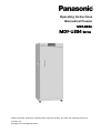
Operating Instructions
Biomedical Freezer
MDF-U334
MDF-U334 Series
MDF-U537/U537D
Please read these instructions carefully before using this product, and save this operating instructions
for future use.
See page 33 for all Model Numbers.
CONTENTS
INTRODUCTION
P. 2
PRECAUTIONS FOR SAFE OPERATION
P. 3
ENVIRONMENTAL CONDITIONS
P. 7
FREEZER COMPONENTS
P. 8
Control panel
P. 10
INSTALLATION SITE
P. 11
INSTALLATION
P. 12
START-UP OF UNIT
P. 13
CHAMBER TEMPERATURE SETTING
P. 13
KEY LOCK FUNCTION
P. 14
REMOTE ALARM TERMINAL
P. 14
ALARM TEMPERATURE SETTING
P. 15
SETTING OF ALARM RESUME TIME
P. 17
ALARMS & SAFETY FUNCTIONS
P. 18
ROUTINE MAINTENANCE
P. 19
Cleaning of cabinet
P. 19
Defrosting
P. 19
TROUBLESHOOTING
P. 20
DISPOSAL OF UNIT
P. 21
Recycle of battery
P. 21
Decontamination of unit
P. 21
DISPOSAL OF BATTERY
P. 26
TEMPERATURE RECORDER (OPTION)
P. 27
Installation of temperature recorder
P. 27
Setting of MTR-4015LH
P. 28
Setting of MTR-G85A or MTR-G85C
P. 30
SPECIFICATIONS
P. 32
PERFORMANCE
P. 33
SAFETY CHECK SHEET
P. 34
1
INTRODUCTION
Read this operating instructions carefully before using the appliance and follow the instructions for
safety operation.
Our company never guarantee any safety if the appliance is used for any objects other than intended
use or used by any procedures other than those mentioned in this operating instructions.
Keep this operating instructions in an adequate place to refer to it as necessary.
The contents of the operating instructions will be subjected to change without notice due to the
improvement of performance or functions.
Contact our sales representative or agent if any page of the operating instructions is lost or page order
is incorrect.
Contact our sales representative or agent if any point in this operating instructions is unclear or if there
are any inaccuracies.
No part of this operating instructions may be reproduced in any form without the expressed written
permission of our company.
CAUTION
Our company guarantees the product under certain warranty conditions.
way shall be responsible for any loss of content or damage of content.
2
Our company in no
PRECAUTIONS FOR SAFE OPERATION
It is imperative that the user complies with this operating instructions
as it contains important safety advice.
Items and procedures are described so that you can use this unit correctly and safely.
If the precautions advised are followed, this will prevent possible injury to the user and
any other person.
Precautions are illustrated in the following way:
WARNING
Failure to observe WARNING signs could result in a hazard to personnel
possibly resulting in serious injury or death.
CAUTION
Failure to observe CAUTION signs could result in injury to personnel and
damage to the unit and associated property.
Symbol shows;
this symbol means caution.
this symbol means an action is prohibited.
this symbol means an instruction must be followed.
Be sure to keep this operating instructions in a place accessible to users of this unit.
Some warning and/or caution labels are attached on the unit. Following shows the description of such
labels.
This label is on the cover in which the electrical components of high voltage are enclosed
to prevent the electric shock. The cover should be removed by a qualified engineer or a
service personnel only.
This symbol means attention or refer to document.
This symbol means earth.
This symbol means power switch “ON”.
This symbol means power switch “OFF”.
< Label on the unit >
This mark is labeled on the cover in which the electrical components of high voltage
are enclosed to prevent the electric shock.
The cover should be removed by a qualified engineer or a service personnel only.
3
PRECAUTIONS FOR SAFE OPERATION
WARNING
Do not use the unit outdoors.
Current leakage or electric shock may result if the unit is exposed to
rain water.
Only qualified engineers or service personnel should install the unit.
The installation by
unqualified personnel may cause electric shock or fire.
Install the unit on a sturdy floor and take an adequate precaution to prevent the unit from
turning over.
If the floor is not strong enough or the installation site is not adequate, this may result
in injury from the unit falling or tipping over.
Never install the unit in a humid place or a place where it is likely to be splashed by water.
Deterioration of the insulation may result which could cause current leakage or electric shock.
Never install the unit in a flammable or volatile location. This may cause explosion or fire.
Never install the unit where acid or corrosive gases are present as current leakage or electric
shock may result due to corrosion.
Always ground (earth) the unit to prevent electric shock.
If the power supply outlet is not
grounded, it will be necessary to install a ground by qualified engineers.
Never ground the unit through a gas pipe, water main, telephone line or lightning rod.
Such
grounding may cause electric shock in the case of an incomplete circuit.
Connect the unit to a power source as indicated on the rating label attached to the unit. Use of
any other voltage or frequency other than that on the rating label may cause fire or electric shock.
Never store volatile or flammable substances in this unit if the container cannot be sealed.
These
may cause explosion or fire.
Do not insert metal objects such as a pin or a wire into any vent, gap or any outlet on the unit.
This may cause electric shock or injury by accidental contact with moving parts.
Use this unit in safe area when treating the poison, harmful or radiate articles.
Improper use
may cause bad effect on your health or environment.
Turn off the power switch (if provided) and disconnect the power supply to the unit prior to any
repair or maintenance of the unit in order to prevent electric shock or injury.
Do not touch any electrical parts (such as power supply plug) or operate switches with a wet
hand.
This may cause electric shock.
4
PRECAUTIONS FOR SAFE OPERATION
WARNING
Ensure you do not inhale or consume medication or aerosols from around the unit at the time of
maintenance.
These may be harmful to your health.
Never splash water directly onto the unit as this may cause electric shock or short circuit.
Never put containers with liquid on the unit as this may cause electric shock or short circuit when
the liquid is spilled.
Never bind, process, or step on the power supply cord, or never damage or break the power
supply plug.
A broken supply cord or plug may cause fire or electric shock.
Do not use the supply cord if its plug is loose.
Such supply cord may cause fire or electric shock.
Never disassemble, repair, or modify the unit yourself.
Any such work carried out by an
unauthorized person may result in fire, or electric shock or injury due to a malfunction.
Disconnect the power supply plug if there is something wrong with the unit.
Continued
abnormal operation may cause electric shock or fire.
When removing the plug from the power supply outlet, grip the power supply plug, not the cord.
Pulling the cord may result in electric shock or fire by short circuit.
Disconnect the power supply plug before moving the unit.
cord.
Take care not to damage the power
A damaged cord may cause electric shock or fire.
Disconnect the power plug when the unit is not used for long periods.
Keeping the connection
may cause electric shock, current leakage, or fire due to the deterioration of insulation.
If the unit is to be stored unused in an unsupervised area for an extended period, ensure that
children do not have access and that doors cannot be closed completely.
The disposal of the unit should be accomplished by appropriate personnel.
Remove doors to
prevent accidents such as suffocation.
Do not put the packing plastic bag within reach of children as suffocation may result.
5
PRECAUTIONS FOR SAFE OPERATION
CAUTION
Use a dedicated power source (a dedicated circuit with a breaker) as indicated on the rating label
attached to the unit.
A branched circuit may cause fire resulting from abnormal heating.
Connect the power supply plug to the power source firmly after removing the dust on the plug.
A dusty plug or improper insertion may cause a heat or ignition.
Never store corrosive substances such as acid or alkali in this unit if the container cannot be
sealed.
These may cause corrosion of inner components or electric parts.
Check the setting when starting up of operation after power failure or turning off of power
switch.
The stored items may be damaged due to the change of setting.
Be careful not to tip over the unit during movement to prevent damage or injury.
Prepare a safety check sheet when you request any repair or maintenance for the safety of service
personnel.
6
ENVIRONMENTAL CONDITIONS
This equipment is designed to be safe at least under the following conditions (based on the IEC 61010-1):
Indoor use;
Altitude up to 2000 m;
o
o
Ambient temperature 5 C to 40 C;
o
Maximum relative humidity 80% for temperature up to 31 C decreasing linearly to 50% relative humidity
o
at 40 C;
Mains supply voltage fluctuations up to ±10% of the nominal voltage;
Transient overvoltages up to the levels of OVERVOLTAGE CATEGORY II;
Temporary OVERVOLTAGES occurring on the mains supply;
Applicable pollution degree of the intended environment (POLUTION DEGREE 2 in most cases);
7
FREEZER COMPONENTS
10
11
12
1
9
2
8
7
3
Hole of Padlock
6
5
4
15
13
14
変更あり
+
N.C. COM N.O.
Back side
8
FREEZER COMPONENTS
1. Lock:
By turning to 180 degree to counterclockwise with a key, the door can be locked.
2. Door:
To open the door, grip the handle.
3. Handle:
Always grip the handle to open the door.
Serves to adjust the height and to settle the frame evenly.
4. Leveling foot:
5. Caster:
four casters are provided for easy movement.
Separate the front two casters from the floor
by adjusting the leveling legs at the time of installation.
6. Defrost water vessel & storage container:
The container can be used to collect the defrosted water
when defrosting.
7. Access port:
8. Door latch:
This is used for leading the measuring cable from the freezing chamber to the outside.
To lock the door, turn this latch downward.
9. Storage container: Made of styrol resin.
at the time of defrosting.
A padlock is also available.
Be careful not to damage the container by a metal scraper
WARNING
Fix the storage container securely. Incomplete installation may cause injury or damage.
Never touch the storage items with wet hands. Touching with the wet hands may cause frostbite
10. Space for temperature recorder:
A temperature recorder (optional part) can be attached here.
See page 27 “TEMPERATURE RECORDER (OPTION)”.
11. Control panel:
To display the temperature setting and running condition.
12. Defrost mark:
When this is hidden by frost, defrost the freezer.
13. Remote alarm terminal:
See page 10 for details.
See to page 19 for instructions.
Used to notify an alarm condition of the unit to remote location.
See page
14 for details.
14. Battery switch:
Switch for battery used for power failure alarm.
Always keep ON.
Turn the switch
OFF when the unit is in no use for a long period (more than one month).
15. Power switch:
Switch for the freezer.
This switch also activates as an over-current breaker (15 A).
9
FREEZER COMPONENTS
Control panel
< MDF-U537D >
1
8
7
1. Alarm lamp (ALARM):
2
6
5
4
3
This lamp is flashed during alarm condition.
2. Digital temperature indicator:
This indicator shows the present chamber temperature or set
temperature.
3. Numerical value shift key (
shift.
):
Pressing this key in the setting mode causes the numerical value to
ON-OFF of key lock can be selected by pressing this key in the key lock mode.
4. Digit shift key (
):
Pressing this key in the setting mode causes the changeable digit to shift.
lock mode is led by pressing this key for more than 5 seconds in the temperature display mode.
Key
Refer to
page 14 for the key lock.
5. Set key (SET):
Temperature setting mode is led by pressing this key.
changeable digit is flashed.
Pressing this key again after setting desired temperature, the setting is
stored into computer memory.
If there is no key operation for ninety seconds during the temperature
setting mode, the temperature setting mode is invalid automatically.
6. Defrost key (DEF):
Once the key is pressed, the
See page 13 for the details.
By pressing this key for five seconds, the refrigerating operation is stopped.
Pressing this key again after defrosting leads resumption of the operation.
Note:
The refrigerating operation never resume automatically after defrosting.
7. Alarm buzzer stop key (BUZZER):
To silence the audible alarm, press this key.
The remote alarm
is also stopped by pressing this key.
(The buzzer cannot be stopped during alarm testing.)
8. Alarm test key (ALARM TEST):
Test key for alarm device.
flashed, remote alarm is activated and buzzer sound.
10
By pressing this key, the alarm lamp is
This means all alarm function operate correctly.
INSTALLATION SITE
To operate this unit properly and to obtain maximum performance, install the unit in a location with the
following conditions:
A location not subjected to direct sunlight
Do not install the unit under direct sunlight.
Installation in a location subjected to direct sunlight cannot
obtain the intended performance.
A location with adequate ventilation
Leave at least 10 cm around the unit for ventilation.
Poor ventilation will result in a reduction of the
performance and consequently the failure.
A location away from heat generating sources
Avoid installing the unit near heat-emitting appliances such as a heater or a boiler etc.
Heat can
decrease the intended performance of the unit.
A location with little temperature change
o
Install the unit under stable ambient temperature.
The allowable ambient temperature is between -5 C
o
and +35 C.
A location with a sturdy and level floor
Always install the unit on a sturdy and level floor.
or injury.
The uneven floor or tilted installation may cause failure
Install the unit in stable condition to avoid the vibration or noise.
Unstable condition may
cause vibration or noise.
WARNING
Install the unit on a sturdy floor.
If the floor is not strong enough or the installation site is not adequate,
this may result in injury from the unit falling or tipping over.
Select a level and sturdy floor for installation.
This precaution will prevent the unit from tipping.
Improper installation may result in water spillage or injury from the unit tipping over.
A location not prone to high humidity
Install the unit in the ambient of 80% R.H. or less humidity.
Installation under high humidity may cause
current leakage or electric shock.
WARNING
Do not use the unit outdoors.
Current leakage or electric shock may result if the unit is exposed to rain
water.
Never install the unit in a humid place or a place where it is likely to be splashed by water.
Deterioration of the insulation may result which could cause current leakage or electric shock.
A location without flammable or corrosive gas
Never install the unit in a flammable or volatile location.
This may cause explosion or fire or may result in
the current leakage or electric shock by the corrosion of the electrical components.
A location without the possibility of anything fall
Avoid installing the unit in the location where anything can fall down onto the unit.
breakdown or failure of the unit.
11
This may cause the
INSTALLATION
1. Removing the packaging materials and tapes
Remove all transportation packaging materials and tapes.
Open the doors and ventilate the unit.
outside panels are dirty, clean them with a diluted neutral dishwashing detergent.
can damage the plastic components.
(Undiluted detergent
For the dilution, refer to the instruction of the detergent.)
cleaning with the diluted detergent, always wipe it off with a wet cloth.
If the
After the
Then wipe off the panels with a dry
cloth.
Note:
Remove the cable tie for banding the power supply cord.
Prolonged banding may cause the corrosion of the cord
coating
2. Adjusting the leveling foot
Extend
the
leveling
feet
by
rotating
counterclockwise to contact them to the floor.
them
Ensure
the unit is level.
3. Fixing the unit
Two fixtures are attached to the rear of the frame.
Fix
the frame to the wall with these fixtures and rope or
Leveling foot
chain.
4. Ground (earth)
The ground (earth) is for preventing the electric shock in
the case of the electrical insulation is somehow
degraded.
Always ground the unit at the time of
installation.
WARNING
Use a power supply outlet with ground (earth) to prevent electric shock.
If the power supply outlet is
not grounded, it is necessary to install a ground by qualified engineers.
Never ground the unit through a gas pipe, water main, telephone line or lightning rod.
grounding may cause electric shock in the case of an incomplete circuit.
5. Installing the short circuit breaker
This product is to be connected to a dedicated circuit protected by branch circuit breaker.
Contact our sales representative or agent.
12
Such
START-UP OF UNIT
Follow the procedures for the initial and consequent operations of the unit.
1. Connect the power cord to the dedicated outlet with appropriate rating.
2. Turn on the power switch.
3. Turn on the battery switch.
The alarm buzzer sometimes operates.
In this case, stop the buzzer by
pressing the alarm buzzer stop key (BUZZER).
4. Set the chamber temperature to the desired temperature.
5. Allow the chamber temperature to fall to the desired temperature.
Check the chamber temperature on
the digital temperature indicator.
6. Press the alarm test key (ALARM TEST) and check that the alarm lamp blinks and alarm buzzer
activates. Also, the remote alarm is activates.
Note: E09 is displayed on the digital temperature indicator when the battery switch is OFF.
7. Begin slowly placing items into the chamber to minimize the temperature rise.
CHAMBER TEMPERATURE SETTING
Table 1 shows the basic procedure for setting the chamber temperature.
sequence indicated in the table.
Perform key operations in the
The example in the table is based on the assumption that the desired
o
temperature is -25 C.
o
Note: Factory setting is the chamber temperature -30 C.
Table 1
Basic operation sequence (Example:
Description of operation
1
2
o
Chamber temperature -25 C)
Key operated
Connect the power cord to the
----
outlet. Turn the power switch ON.
Press set key.
SET
The second digit of the temperature
indicator flashes.
moves.
digit shift key and the numerical
By pressing the key, the numerical
value shift key.
4
displayed.
By pressing the key, settable digits
Set the temperature to 25 with the
3
Indication after operation
The current chamber temperature is
value of the settable digit increases.
Press set key.
SET
The current chamber temperature is
displayed.
o
o
Although the value of the chamber temperature setting can range from -18 C to -35 C, the guaranteed
o
o
temperature when there is no load is -30 C when the external temperature is 30 C.
13
KEY LOCK FUNCTION
This unit is provided with the key lock function. When the key lock is ON, change of temperature setting
through the key pad is not available. The key lock is set in OFF at the factory.
Display
L0
L1
Table 2
Mode
Key lock is OFF
Key lock is ON
Function
Enable to change of temperature setting
Disable to change of temperature setting
Procedure for key lock setting (change from key lock OFF to key lock ON)
Description of operation
Key
Indication after operation
operated
1
The current chamber temperature is
displayed.
----
2
Press digit shift key for 5 seconds.
The right digit is flashed.
3
Press numerical value shift key and
scroll the figure to 1.
4
Press set key.
When pressed, the figure of settable
digit increases.
The key lock is set to ON.
The current chamber temperature is
displayed.
SET
The key lock only works with the chamber temperature setting and the defrost key (DEF).
REMOTE ALARM TERMINAL
WARNING
Always disconnect the power supply cord before connecting an alarm device to the remote alarm
terminal.
The terminal of the remote alarm is installed at the upper side of the unit.
this terminal. Contact capacity is DC 30 V, 2 A.
The alarm is outputted from
Contact output:
between COM. and N.O.
between COM. and N.C.
At normal
Open
Close
At abnormal
Close
Open
Note:
The buzzer is silenced by pressing buzzer stop key (BUZZER) on the control panel during alarm
condition. (A remote alarm is continuing the operation.)
The buzzer will be activated again after certain suspension if the alarm condition is continued.
The alarm is actuated when the power supply plug is disconnected from the outlet or the power switch is
OFF.
Use a twisted sealed wire for the connection.
Type UL2343, UL2448, UL2464, UL2552, UL 2623
Length: thirty meter max.
14
ALARM TEMPERATURE SETTING
This unit is provided with both high and low temperature alarms. The temperature at which the alarm is
activated may be changed.
o
o
o
o
The available set range for high temperature alarm is between +5 C and +15 C, and -5 C and -15 C for
low temperature alarm against the set temperature.
o
Note:
The temperature alarm is set at ±10 C of the set temperature at the factory.
Display
Mode
Function
F01
High temperature alarm set
See Table 3 on page 15
F02
Low temperature alarm set
See Table 4 on page 16
As an example, Table 3 shows the procedure to set the high temperature alarm so that the alarm can
o
activate when the chamber temperature is 5 C higher than the set temperature.
Table 4 shows the procedure to set the low temperature alarm so that the alarm can activate when the
o
chamber temperature is 5 C lower than the set temperature.
Table 3
Procedure for setting high temperature alarm
Description of operation
Key
Indication after operation
operated
----
1
2
3
4
displayed.
Press numerical value shift key for
The first digit is flashed.
five seconds.
Press numerical value shift key and
When pressed, the figure of settable
scroll the figure to 1.
digit increases.
Press set key.
SET
The right digit is flashed.
Pressing the key shifts the digit which can be set.
Set the temperature to 005 with the
5
The current chamber temperature is
digit shift key and numerical value
When pressed, the figure of settable
shift key.
digit increases.
Alarm temperature is memorized and
6
Press set key.
SET
the current chamber temperature is
displayed.
The set mode returns to the temperature display mode automatically when ninety seconds has passed
without any key operation.
In this case, any setting before pressing set key (SET) is not memorized.
15
ALARM TEMPERATURE SETTING
Table 4
Procedure for setting low temperature alarm
Description of operation
Key
Indication after operation
operated
----
1
2
3
4
Press numerical value shift key for
The right digit is flashed.
five seconds.
Press numerical value shift key and
When pressed, the figure of settable
scroll the figure to 2.
digit increases.
Press set key.
SET
The right digit is flashed.
Pressing the key shifts the digit which can be set.
Set the temperature to -05 with the
5
The current chamber temperature is
displayed.
digit shift key and numerical value shift
When pressed, the figure of settable
key.
digit increases.
Alarm temperature is memorized and
6
Press set key.
SET
the current chamber temperature is
displayed.
The set mode returns to the temperature display mode automatically when ninety seconds has passed
without any key operation.
In this case, any setting before pressing set key (SET) is not memorized.
16
SETTING OF ALARM RESUME TIME
The alarm buzzer and remote alarm is stopped by pressing alarm buzzer stop key (BUZZER) on the
control panel during alarm condition.
The buzzer and remote alarm terminal will be activated again after
certain suspension if the alarm condition is continued.
The suspension time can be set by following the
procedure shown in the Table 5 below.
The example in the table is based on the assumption that the desired duration is twenty minutes.
Note: The duration is set in thirty minutes at the factory.
Table 5
Setting procedure for alarm resuming time (change from 30 minutes to 20 minutes)
Description of operation
----
1
2
Key operated
The current chamber temperature is
displayed.
Press numerical value shift key for
The first digit is flashed.
5 seconds.
Pressing the key shifts the digit which can be set.
Set the figure to F25 with the
3
digit shift key and numerical value
When pressed, the figure of settable
shift key.
4
5
Indication after operation
digit increases.
Press set key.
SET
The current resume time is displayed.
The middle digit is flashed.
Set the figure to 020 with the
When pressed, the figure of settable
numerical value shift key.
digit increases.
Alarm resume time is memorized and
6
Press set key.
SET
the current chamber temperature is
displayed.
The settable alarm resume time is 10, 20, 30, 40, 50, or 60 minutes (The setting is 010, 020, 030, 040,
050, or 060). The buzzer would not resume if the resume time is set in 000.
The setting of alarm resume time cannot be changed during the defrosting.
The buzzer and remote alarm during power failure or alarm testing cannot be silenced.
The set mode returns to the temperature display mode automatically when ninety seconds has passed
without any key operation.
In this case, any setting before pressing set key (SET) is not memorized.
17
ALARMS & SAFETY FUNCTIONS
This unit has the alarms and safety functions shown in Table 6, and also self diagnostic functions.
Table 6
Alarms and safety functions
Alarm & Safety
High temperature
alarm
Low temperature
alarm
Power failure alarm
Auto-return
Situation
If the chamber temperature is higher
than the temperature at which the
high temperature alarm is activated.
If the chamber temperature is lower
than the temperature at which the
low temperature alarm is activated.
In the case of power failure.
When power switch is turned OFF.
When the power to the unit is
disconnected.
When there is no key pressing in
each setting mode for 90 seconds.
Key lock
When the key lock is “ON”.
Battery switch
check
When battery switch is OFF at the
time of alarm test.
Thermal sensor
Abnormality
Ambient sensor
abnormality
Compressor
protection sensor
abnormality
Compressor temp.
Abnormality
Indication
Alarm lamp is flashed.
Digital temperature indicator is
flashed.
Alarm lamp is flashed.
Digital temperature indicator is
flashed.
Alarm lamp is flashed.
Buzzer
Intermittent tone with
15 minutes delay.
Remote alarm with 15
minutes delay.
Intermittent tone with
15 minutes delay.
Remote alarm with 15
minutes delay.
Intermittent tone
Remote alarm.
Chamber temperature is
displayed.
-----
----Alarm lamp is flashed.
E09 is flashed.
Alarm lamp is flashed.
E01 and chamber temp.
are displayed alternately.
Alarm lamp is flashed.
If the thermal sensor is
E02 and chamber temp.
short-circuited.
are displayed alternately.
Alarm lamp is flashed.
If the ambient temperature sensor is
E03 and chamber temp.
disconnected.
are displayed alternately.
Alarm lamp is flashed.
If the ambient temperature sensor is
E04 and chamber temp
short-circuited.
are displayed alternately.
Alarm lamp is flashed.
If the compressor protection
E05 and chamber temp.
temperature sensor is disconnected.
Are displayed alternately.
If the compressor protection
Alarm lamp is flashed.
temperature sensor is short
E06 and chamber temp.
circuited.
Are displayed alternately.
In the case of failure of compressor
cooling fan motor.
E10 and chamber temp. are
In the case of abnormal high temp.
displayed alternately.
due to the dust on the condenser.
In the case of abnormal high
ambient temperature.
If the thermal sensor is
disconnected.
Safety operation
-----
Finishing of each
setting mode.
Change of setting is
disable.
Intermittent tone
Remote alarm.
Intermittent tone
Remote alarm.
Continuous running.
Intermittent tone
Remote alarm.
Continuous running.
Intermittent tone
Remote alarm.
Intermittent tone
Remote alarm.
Intermittent tone
Remote alarm.
Normal operation.
Intermittent tone
Remote alarm.
Compressor stops
running when the temp
reaches about 80oC.
Battery check
When about three years has passed _F1 and chamber temp.
with power switch ON.
are displayed alternately.
-----
Information only
Fan motor check
When about six years has passed _F2 and chamber temp.
with power switch ON.
are displayed alternately.
-----
Information only
The above power failure alarm is available when the battery switch is ON and the battery is charged. If
the battery switch is OFF or the battery is discharged, only the remote alarm is activated.
The power failure alarm can be kept about twelve hours with the battery charged completely. 2-day
operation of the freezer is needed to charge the battery full.
The chamber temperature is displayed for five seconds if the alarm buzzer stop key (BUZZER) is
depressed during the power failure alarm. At the same time, the alarm buzzer stops.
The remote alarm is stopped by pressing alarm buzzer stop key (BUZZER) as the remote alarm is
operated in conjunction with the buzzer, except for the power failure alarm.
After power failure, the operation is resumed with the condition before power failure since the
temperature setting and alarm temperature setting are memorized in a nonvolatile memory.
The following directions are the information of the part replacement (it is recommendation). This is not
a trouble.
a) The battery for power failure alarm is an article for consumption. It is recommended that the battery
will be replaced about every three years. Contact our sales representative or agent at the time of
replacement of the battery for recycling.
b) Fan motors are expendable supplies. Replace it for about every six years. Contact our sales
representative or agent at the time of replacement of the fan motor.
18
ROUTINE MAINTENANCE
WARNING
Always disconnect the power supply to the unit prior to any repair or maintenance of the unit in
order to prevent electric shock or injury.
Ensure you do not inhale or consume medication or aerosols from around the unit at the time of
maintenance.
These may be harmful to your health.
CAUTION
Always put on the dry gloves to protect the hands at the time of maintenance.
No gloves may cause
cut of the finger by the edge or corner.
Cleaning of cabinet
Clean the unit once a month.
Regular cleaning keeps the unit looking new.
Use a dry cloth to wipe off small amounts of dirt on the outside and inside of the unit and all accessories.
If the outside panels are dirty, clean them with a diluted neutral dishwashing detergent.
detergent can damage the plastic components.
After the cleaning with the diluted detergent, always wipe it off with a wet cloth.
or accessories with a dry cloth.
Never pour water onto or into the unit.
(Undiluted
For the dilution, refer to the instruction of the detergent.)
Then wipe off the cabinet
Doing so can damage the electric insulation and cause failure.
The compressor and other mechanical parts are completely sealed.
This unit requires absolutely no
lubrication.
Defrosting
Defrost the freezer whenever one of the defrost marks shown by 12 in the figure on page 9 is hidden by
frost.
Use the scraper provided for removing the frost if the freezer operation must be continued.
Pay attention
not to impact or damage the inner wall.
1. When defrosting, temporarily move all the contents of containers in the freezer to another
low-temperature freezer.
2. Place the empty defrost water vessel & storage container inside the freezer.
3. Press defrost key (DEF) for five seconds to stop the refrigerating operation.
While the refrigerating
operation is stopped, the current chamber temperature and dF is displayed on the digital temperature
indicator alternately.
4. After a several hours, check visually that all defrost was removed completely.
5. Throw out the water that has accumulated in the defrost water vessel & storage container, then wipe
the inside of the freezer.
6. Press defrost key (DEF) so that the refrigerating operation can be started.
7. Once the chamber temperature has dropped to the desired temperature, place the original contents
back in the freezer chamber.
Note:
After the defrosting, the refrigerating operation is never resumed automatically.
defrost key (DEF) to start the freezer operation after defrosting.
19
Make sure to press
TROUBLE SHOOTING
If the unit malfunctions, check out the following before calling for service.
Malfunction
The chamber is not cooled
Check/Remedy
The circuit breaker of power source is active.
at all
The voltage is too low (In this case, call an electrician.)
The power switch is not ON.
The large amount of articles (load) is stored in the chamber at one
time.
The freezer is in defrost condition.
The cooling is poor
The ambient temperature is too high.
The door is not closed firmly.
The large amount of frost is built on the chamber wall.
The set temperature is not inputted properly.
The freezer is in the direct sunlight.
There is any heating source near the freezer.
A rubber cap and insulation for the access port are not set correctly.
You put too many unfrozen articles into the freezer compartment.
When the unit does not
The key lock is set in ON mode.
accept changes of
temperature setting
Noise
The freezer is not installed on the sturdy floor.
The freezer is not leveled with the leveling feet.
There is anything touching the frame.
The freezer is in the status immediately after start up.
The unit sometimes causes a noise when the chamber temperature is
high due to the large load.
The noise gets less and less accompanying
with the cooling of the chamber.
If the malfunction is not eliminated after checking the above items, or the malfunction is not shown in the
above table, contact our sales representative or agent.
20
DISPOSAL OF UNIT
WARNING
If the unit is to be stored unused in an unsupervised area for an extended period ensure that children do
not have access and doors cannot be closed completely.
The disposal of the unit should be accomplished by appropriate personnel.
Always remove
doors to prevent accidents such as suffocation.
Recycle of battery
The unit contains a rechargeable battery.
The battery is recyclable.
At the end
of it’s useful life, check with you local solid officials option or proper disposal.
廢電池
請回收
*Label indication is obliged to comply with Taiwanese battery regulation.
Decontamination of unit
Before disposing a biomedical freezer with biohazardous danger, decontaminate the biomedical freezer to
the extent possible by the user.
21
DISPOSAL OF UNIT
(English)
FOR EU USERS
The symbol mark and recycling systems described below apply to EU countries and do not apply to
countries in other areas of the world.
Your Panasonic product is designed and manufactured with high quality materials and components which
can be recycled and/or reused.
The symbol mark means that electrical and electronic equipment, batteries and accumulators, at their
end-of-life, should be disposed of separately from your household waste.
Note:
If a chemical symbol is printed beneath the symbol mark, this chemical symbol means that the battery or
accumulator contains a heavy metal at a certain concentration. This will be indicated as follows: Hg:
mercury, Cd: cadmium, Pb: lead
In the European Union there are separate collection systems for used electrical and electronic equipment,
batteries and accumulators.
Please, dispose of them correctly at your local community waste collection/recycling centre.
Please, help us to conserve the environment we live in!
(German)
Für EU-Staaten
Das Symbol und das erwähnte Wiederverwertungssystem gelten nur für die Länder der EU und nicht für
andere Länder oder Gebiete in der Welt.
Die Produkte von Panasonic werden aus hochwertigen Materialien und Komponenten gefertigt, die sich
wieder verwenden lassen.
Das Symbol bedeutet, dass elektrische oder elektronische Geräte, Batterien und Akkus am Ende ihrer
Lebensdauer nicht im Haushaltmüll entsorgt werden dürfen.
Hinweis:
Ein chemisches Zeichen unter dem Symbol bedeutet, dass die Batterie bzw. der Akku Schwermetalle in
gewissen Konzentrationen enthält. Die Metalle werden wie folgt bezeichnet: Hg: Quecksilber, Cd:
Kadmium, Pb: Blei
In der Europäischen Union gibt es separate Sammelstellen für elektrische und elektronische Geräte,
Batterien und Akkus.
Entsorgen Sie solche Geräte bitte richtig in der kommunalen Sammelstelle bzw. im Recyclingzentrum.
Helfen Sie mit, die Umwelt in der wir leben, zu schützen.
22
DISPOSAL OF UNIT
(French)
POUR LES UTILISATEURS DE UE
Le symbole et les systèmes de recyclage évoqués ci-dessous s'appliquent uniquement aux pays de UE.
Votre produit Panasonic est conçu et fabriqué avec des composants et des matériaux de hautes qualités
qui peuvent être recyclés et/ou réutilisés.
Le symbole signifie que les équipements électriques et électroniques, les batteries et les accumulateurs
ne doivent pas être mis au rebut avec les déchets domestiques à l'issue de leur durée de vie.
Remarque:
Si un symbole chimique est imprimé sous le symbole, le symbole chimique indique que la batterie ou
l'accumulateur contient une certaine concentration de métaux lourds. Les métaux sont indiqués de la
manière suivante: Hg: mercure, Cd: cadmium, Pb: plomb.
Il existe différents systèmes de collecte pour les équipements électriques et électroniques, les batteries et
les accumulateurs usagés au sein de l'Union européenne.
Veuillez mettre les équipements au rebut de manière correcte, auprès de votre centre de recyclage/de
collecte des déchets local.
Aidez-nous à préserver l'environnement dans lequel nous vivons!
Les machines ou appareils électriques et électroniques contiennent fréquemment des matières qui, si
elles sont traitées ou éliminées de manière inappropriée, peuvent s’avérer potentiellement dangereuses
pour la santé humaine et pour l’environnement.
Cependant, ces matières sont nécessaires au bon fonctionnement de votre appareil ou de votre machine.
Pour cette raison, il vous est demandé de ne pas vous débarrasser de votre appareil ou machine usagé
avec vos ordures ménagères.
(Spanish)
PARA USUARIOS DE LA UNION EUROPEA
El símbolo y los sistemas de reciclado descriptos a continuación se aplican para países de la Unión
Europea y no se aplica para países en otras áreas del mundo.
Su producto Panasonic fue diseñado y fabricado con materiales de alta calidad y componentes que
pueden ser reciclados y/o vueltos a usar.
El símbolo significa que los equipos eléctricos y electrónicos, baterías y acumuladores, al final de su vida
útil, debe ser desechados separadamente de sus residuos domiciliarios.
Nota:
Si hay un símbolo químico impreso debajo del símbolo, este símbolo químico significa que la batería o
acumulador contiene una cierta concentración de un metal pesado. Esto es indicado de la siguiente
manera: Hg: mercurio, Cd: cadmio, Pb: plomo
En la Unión Europea hay sistemas de recolección separados para equipos eléctricos y electrónicos,
baterías y acumuladores usados.
Por favor, disponga de ellos correctamente en el centro de recolección de residuos/reciclado de la
comunidad de su localidad.
Por favor, ayúdenos a proteger el medio ambiente en que vivimos!
23
DISPOSAL OF UNIT
(Portuguese)
PARA UTILIZADORES DA UE
O símbolo e os sistemas de reciclagem descritos abaixo aplicam-se aos países da UE e não se aplicam
aos países noutras áreas do mundo.
O seu produto Panasonic foi concebido e fabricado com materiais e componentes de elevada qualidade
que podem ser reciclados e/ou reutilizados.
O símbolo significa que o equipamento eléctrico e electrónico, baterias e acumuladores, em final de vida,
não devem ser deitados fora juntamente com o lixo doméstico.
Atenção:
Se estiver impresso um símbolo químico debaixo do símbolo de , este símbolo químico significa que a
bateria ou acumulador contém um metal pesado numa determinada concentração. Estará indicado da
seguinte forma: Hg: mercúrio, Cd: cádmio, Pb: chumbo
Na União Europeia existem sistemas de recolha separados para equipamento eléctrico e electrónico,
baterias e acumuladores.
Por favor, entregue-os no seu centro de reciclagem/recolha de lixo local.
Por favor, ajude-nos a conservar o ambiente!
(Italian)
PER UTENTI UE
Il simbolo e i sistemi di riciclaggio descritti di seguito si applicano esclusivamente ai paesi dell’UE.
Questo prodotto Panasonic è stato progettato e realizzato con materiali e componenti di elevata qualità
che possono essere riciclati e/o riutilizzati.
Il simbolo di riciclaggio mostrato di seguito indica che i dispositivi elettrici ed elettronici, le batterie e gli
accumulatori, una volta esauriti, devono essere smaltiti separatamente rispetto ai rifiuti domestici.
Nota:
Se sotto il simbolo di riciclaggio appare un simbolo chimico, esso sta ad indicare che la batteria o
l’accumulatore contengono metalli pesanti a determinate concentrazioni. Questo viene specificato come
segue: Hg: mercurio, Cd: cadmio, Pb: piombo.
Nell’Unione europea esistono diversi sistemi per la raccolta dei rifiuti speciali quali i dispositivi elettrici ed
elettronici, le batterie e gli accumulatori.
Si raccomanda di provvedere allo smaltimento di tali rifiuti secondo quanto previsto dalle normative vigenti
in materia.
Aiutaci a conservare l’ambiente!
24
DISPOSAL OF UNIT
(Dutch)
VOOR GEBRUIKERS IN DE EU
Het symbool en de recycleersystemen die hieronder beschreven worden, zijn van toepassing op de
landen in de EU en zijn niet van toepassing op landen in andere delen van de wereld.
Uw Panasonic product is ontworpen en gemaakt met materialen en onderdelen van hoge kwaliteit, die
gerecycleerd en opnieuw gebruikt kunnen worden.
Het symbool betekent dat elektrische en elektronische apparatuur, batterijen en accu's aan het eind van
hun leven apart van uw huisafval weggegooid moeten worden.
Let op:
Indien een chemisch symbool afgedrukt staat onder het symbool, betekent dit chemisch symbool dat de
batterij of accu een zwaar metaal met een bepaalde concentratie bevat. Dit wordt als volgt aangegeven:
Hg: kwik, Cd: cadmium, Pb: lood
In de Europese Unie zijn afzonderlijke inzamelingssystemen voor gebruikte elektrische en elektronische
apparatuur, batterijen en accu's.
Wilt u deze op de juiste manier weggooien bij uw plaatselijk afvalinzameling-/recyclingcentrum in uw
buurt?
Help ons het milieu waarin wij leven in stand te houden!
(Swedish)
FÖR ANVÄNDARE INOM EU
Den symbolmärkning och de återvinningssystem som beskrivs här nedan gäller länder inom EU och gäller
inte länder i någon annan del av världen.
Din Panasonic-produkt har konstruerats och tillverkats med delar och material av hög kvalitet, som kan
återvinnas och/eller återanvändas.
Symbolmärkningen innebär att elektrisk och elektronisk utrustning, batterier och ackumulatorer, vid slutet
av deras livslängd, inte får slängas som hushållsavfall utan skall slängas separat.
Observera:
Om en kemisk symbol finns tryckt under denna symbolmärkning, betyder denna kemiska symbol att
batteriet eller ackumulatorn innehåller en tungmetall med en viss koncentration. Detta indikeras på
följande sätt: Hg: kvicksilver, Cd: kadmium, Pb: bly
I den Europeiska Unionen finns det separata uppsamlingssystem för använd elektrisk och elektronisk
utrustning, batterier och ackumulatorer.
Gör dig av med sådana saker på rätt sätt på den speciella lokala platsen för återsamling/återanvändning.
Hjälp oss att bevara den miljö vi lever i!
25
DISPOSAL OF BATTERY
This unit is provided a nickel-metal-hydride battery for the power failure warning device.
located in the electrical box.
The battery is
(Fig. 1)
The high voltage components are enclosed in the electrical box.
The cover should be removed
by a qualified engineer or a service personnel only to prevent the electric shock.
Disposal of nickel-metal-hydride battery
1. Turn off the power switch and disconnect the power supply plug.
2. Remove six screws fixing the top cover with a screw driver and remove the top cover. (Fig. 1)
3. Remove two screws fixing the battery mounting plate (Fig. 2) and disconnect the battery connector (Fig.
3).
4. Take out the battery. (Fig.4)
5. Follow the procedure for recycling or proper disposal.
Handling of battery
Cover the battery terminal with an insulating tape to avoid the short circuit.
Then follow the procedure for
recycling or proper disposal.
Top cover
Screw
Electrical box
Fig. 2
Fig. 1
Battery connector
Battery
mounting plate
Battery
Battery
connector
Battery
Fig. 4
Fig. 3
26
TEMPERATURE RECORDER (OPTION)
Installation of temperature recorder
WARNING
Always disconnect the power supply to the unit prior to attachment of a temperature recorder in
order to prevent electric shock or injury.
A temperature recorder is available for the biomedical freezer as the optional component.
the temperature recorder is MTR-G85A, MTR-G85C and MTR-4015LH.
For the attachment, the
recorder fixing is necessary.
Following shows the combination of recorder with the recorder fixing:
Temperature recorder
Recorder fixing
MTR-4015LH (folding chart type)
----
MTR-G85A or MTR-G85C (circular chart type)
MDF-S740T
Contact our sales representative or agent for the installation of a temperature recorder.
MTR-G85A or MTR-G85C
MDF-S740T
27
The type of
TEMPERATURE RECORDER (OPTION)
Setting of MTR-4015LH
Pull the knob on the upper part of the temperature
recorder forward to change the recording paper or battery.
Setting of recording paper
1. The information on the temperature recording paper is
shown in Fig. 1.
Fig. 1
2. Pull the cartridge up after opening the top lid.
The lid
can be opened by turning the knob counterclockwise.
See Fig. 2.
3. As shown in Fig. 3, insert the recording paper with the
“begin” tab placed in the cartridge.
Check that the
printed side is facing out.
4. Place the recording paper beneath the arm and
Fig. 2
between the plate spring and guide plate in the direction of
the arrow.
Note:
Do not scratch or put pressure on the recording paper.
Do not bend the recording paper.
Fig. 3
Do not reverse the recording paper manually.
The used chart paper left in the used chart compartment
can cause a malfunction.
Be sure to remove it.
See Fig.
4.
Fig. 4
28
TEMPERATURE RECORDER (OPTION)
5. Place the recording paper between the guide and the
guide plate.
Slide the recording paper along the guide
plate so that the recording paper will not be forced out of
the date/hour slot.
See Fig. 5.
6. After ascertaining that the holes on the side of the
recording paper are locked into the teeth of the sprocket,
turn the gear and send the recording paper into the used
chart compartment.
Fig. 5
Setting of time
1. Turn the gear on the date/hour slot to the desired time.
2. After properly folding the recording paper in the used or
unused
recording
paper
compartment,
replace
the
cartridge.
Removing of the used recording paper
After recording, take out the cartridge and remove the
recording paper from the recording paper outlet.
Fig. 6
If not all
of the recording paper has been fed into the used recording
paper compartment, send all the recording paper in the
compartment first turning the gear.
Battery replacement
To replace the battery, turn the knob counterclockwise to open the lid. Place the battery in the battery
case according to the plus-minus indications on the bottom of the battery case. See Fig. 6.
Note :
This temperature recorder is designed for the manganese dry cell and the alkaline dry cell.
Do not use a rechargeable battery because the initial voltage of such battery is low.
The rechargeable
battery may cause the malfunction of temperature recorder or shorten the battery life significantly.
Start-up
1. The quartz motor is started by placing a “R14” or size “C” dry cell battery in the battery case.
2. Check the operation of the temperature recorder using the quartz motor rotation check gear.
3. Replace the battery once a year.
Stopping
The temperature recorder is stopped by taking the battery out of the battery case.
29
TEMPERATURE RECORDER (OPTION)
Setting of MTR-G85A or MTR-G85C
Pull the knob on the upper part of the temperature recorder forward to change the recording paper.
Chart guides
Pen arm
Back-up battery
Chart hub cover
Recording paper
Pen lifter
Ink pen
Key lock
Open cover latch
Chart speed selector
Pilot lamp
Fast feed button
Power switch
Zero adjustment screw
Loading the ink pen:
1. Slightly raise the end of the pen lifter and remove from the lifter
stopper. Then rotate clockwise as shown in Fig. 1.
2. Remove the ink pen from the bag and remove its cap. The cap
can be conveniently kept on the cap holder located at the upper left
corner.
NOTE: Loading a pen, turn the power OFF and then ON again to
return to the normal mode. (Refer to Fig. 2 when loading a ink pen.
Fig. 1
3. Press both sides of the pen arm as indicated by the arrows to open
the head clamp at A and B. (See to Fig. 2 illustration 1)
4. Position the ink pen so that the guide pins fit into the guide holes
on the pen arm. (See to Fig. 2 illustration 2)
5. Press the two sides of the head clamp as indicated by the arrows
to secure the ink pen. (See to Fig. 2 illustration 3) From the side
view, the cartridge should fit perfectly on the arm. Confirm that the
pen arm is attached to both sides of the ink pen.
Ink pen
1
2
3
6. After loading the ink pen, return the pen lifter to the
original position.
Confirm that the pen lifter has
Ink pen
securely entered the pen lifter stopper.
Pen arm
Fig. 2
30
TEMPERATURE RECORDER (OPTION)
Starting recording and setting the time:
Turn the power switch ON.
The pen will move inward on
the circular recording paper and stop temporarily at the 0%
o
position (equivalent to the 40 C line).
Then the pen will
move to the position which indicates the measured
temperature.
Ink pen
(Fig. 3)
Hour
Temperature
Time setting Method:
Place the recording paper at a position slightly in front of the
desired time (the chart is rotated to the left).
Set the time
0 % position
equivalent to
o
40 C line
by using the fast feed button to quickly rotate the chart.
The fast feed button can be used to accurately set the time.
Fig. 3
When the recording paper speed is set to thirty two
days:
The center of the recording paper is divided into thirty two
equal sections.
The lines extending from these lines serve
as the thirty two day time scale.
(Fig. 4)
Stopping recording:
1. Turn OFF the power switch.
2. When recording is stopped for a prescribed period, place
the caps back on the ink pen to prevent the ink from
Fig. 4
evaporating.
Replacing the recording paper:
1. Slightly raise the end of the ink pen lifter and remove from the ink pen lifter stopper.
Rotate the tip of
the ink pen clockwise until it rests on top of the ink pen lifter.
2. Remove the chart hub cover, and then replace the recording paper.
3. Place the chart hub cover. Remove and dispose of the piece of recorder paper. Confirm that the new
recorder paper is inside of the chart guides.
4. Set the correct time.
31
SPECIFICATIONS
Biomedical Freezer
Product name
External dimensions
Internal dimensions
MDF-U334
W614 mm x D709 mm x
H1620 mm
W490 mm x D486 mm x
H1290 mm
Effective capacity
274 L
Exterior
Painted steel
Interior
Styrol resin
Insulation
Rigid polyurethane foamed-in place
Outer door
Painted steel
Lock
1
Caster
4
Leveling foot
2
Evaporator
Tube on sheet type (also used as a shelf)
Diameter 30 mm
Access port
1 on left side
Condenser
Wire and tube type
Compressor
Hermetic type, 200 W
Refrigerant
R-134a
o
o
Temperature controller
Electronics controller (between -18 C and -35 C)
Temperature display
Digital display (between -50 C and +50 C)
Temperature sensor
Thermistor sensor
Temperature alarm
Flash of digital indicator and alarm lamp, Buzzer, (Remote alarm)
o
o
1 set of key, 1 scraper, 4 card holders,
4 large baskets
Accessories
W446 mm x D369 mm x H220 mm
1 small basket
W487 mm x D221 mm x H155 mm
Weight
81 kg
Battery
Nickel hydrogen battery, DC 6 V, 1100 mAh (5HR-AAC), Automatic charge
Optional component
Temperature recorder (MTR-4015LH)
Temperature recorder (MTR-G85A, MTR-G85C)
Recorder fixing for MTR-G85A, MTR-G85C (MDF-S740T)
Interface board (MTR-480, MTR-L03)
Data acquisition system (MTR-5000)
Note:
Design or specifications will be subject to change without notice.
Refer to the updated catalog when ordering an optional component.
32
PERFORMANCE
Biomedical Freezer
Product name
Model number.
MDF-U334
MDF-U334-PT MDF-U334-PA MDF-U334-PB MDF-U334-PK MDF-U334-PE
o
Cooling performance
o
Temperature control range
Rated voltage
Rated frequency
Rated power consumption
Noise level
o
-30 C (ambient temperature; 35 C, no load)
o
-20 C to -30 C
AC 110 V
AC 115 V
AC 220 V
AC 220 V
60 Hz
60 Hz
50 Hz
60 Hz
135 W
140 W
130 W
145 W
35 dB [A] (background noise; 20 dB)
Maximum pressure
1360 kPa
Note :The unit with CE mark complies with EC directives.
33
AC 220 V/
230 V/240 V
50 Hz
130 W/
135 W/140 W
CAUTION
Please fill in this form before servicing.
Hand over this form to the service engineer to keep for his and your safety.
Safety check sheet
1. Freezer contents :
Risk of infection:
Risk of toxicity:
Risk from radioactive sources:
□Yes
□No
□Yes
□Yes
□Yes
□No
□No
□No
(List all potentially hazardous materials that have been stored in this unit.)
Notes :
2. Contamination of the unit
Unit interior
No contamination
Decontaminated
Contaminated
Others:
□Yes
□No
□Yes
□Yes
□Yes
□No
□No
□No
3. Instructions for safe repair/maintenance of the unit
a) The unit is safe to work on
□Yes
□No
b) There is some danger (see below)
□Yes
□No
Procedure to be adhered to in order to reduce safety risk indicated in b) below.
Date :
Signature :
Address, Division :
Telephone :
Product name :
Biomedical Freezer
Model :
Serial number :
MDF-
Please decontaminate the unit yourself before calling the service engineer.
34
Date of Installation :
1-1-1, Sakata Oizumi-Machi Ora-Gun, Gunma 370-0596, Japan
© Panasonic Healthcare Co., Ltd. 2012
Printed in Japan
7FB6P151619001
S0412-10412