1
STP 10-92A12-SM-TG
Soldier’s Manual and Trainer’s Guide
MOS 92A
AUTOMATED LOGISTICAL SPECIALIST
SKILL LEVELS 1 AND 2
MAY 2008
DISTRIBUTION RESTRICTION: Approved for public release; distribution is unlimited.
HEADQUARTERS
DEPARTMENT OF THE ARMY
This publication is available at
Army Knowledge Online (www.us.army.mil)
and the General Dennis J. Reimer
Training and Doctrine Digital Library at
(www.train.army.mil)
*STP 10-92A12-SM-TG
SOLDIER TRAINING
PUBLICATION
No. 10-92A12-SM-TG
HEADQUARTERS
DEPARTMENT OF THE ARMY
Washington, D.C., 7 May 2008
SOLDIER'S MANUAL and TRAINER'S GUIDE
MOS 92A
Automated Logistical Specialist
Skill Levels 1 and 2
CONTENTS
Page
Preface ......................................................................................................................................................... v
Chapter 1. Introduction........................................................................................................................... 1-1
1-1. General........................................................................................................................... 1-1
1-2. Trainer’s Responsibilities ...............................................................................................1-1
1-3. Soldier’s Responsibilities................................................................................................ 1-2
1-4. Training Tips................................................................................................................... 1-2
1-5. Training Support............................................................................................................. 1-3
1-6. Career Progression Training .......................................................................................... 1-3
1-7. Career Progression ........................................................................................................ 1-4
Chapter 2. Training Guide ...................................................................................................................... 2-1
2-1. General........................................................................................................................... 2-1
2-2. Subject Area Codes .......................................................................................................2-2
2-3. Duty Position Training Requirements............................................................................. 2-3
2-4. Critical Tasks List ........................................................................................................... 2-4
DISTRIBUTION RESTRICTION: Approved for public release; distribution is unlimited.
*This publication supersedes STP 10-92A12-SM-TG, 18 December 2007.
i
STP 10-92A12-SM-TG
Page
Chapter 3. MOS/Skill Level 10 and 20 Tasks ........................................................................................ 3-1
Skill Level 1
101-92A-1001
101-92A-1002
101-92A-1003
101-92A-1004
101-92A-1005
101-92A-1006
101-92A-1007
101-92A-1008
101-92A-1009
Subject Area 1: Basic Supply Principles
Maintain Required Publications ............................................................................... 3-1
Establish Supply and Maintenance Files ................................................................. 3-4
Perform FEDLOG Data Inquiries ............................................................................. 3-9
Prepare Delegation of Authority Documents .........................................................3-13
Receive an Item of Supply .....................................................................................3-16
Issue an Item of Supply..........................................................................................3-20
Turn In an Item of Supply.......................................................................................3-23
Request an Item of Supply.....................................................................................3-27
Maintain a Document Register...............................................................................3-33
101-92A-1010
101-92A-1011
101-92A-1012
101-92A-1013
101-92A-1014
101-92A-1015
Subject Area 2: Basic Storage Procedures
Store an Item of Supply..........................................................................................3-36
Perform the Proper Handling of Hazardous Materiel.............................................3-40
Conduct an Inventory .............................................................................................3-44
Perform Care of Supplies.......................................................................................3-47
Operate Materiel Handling Equipment (MHE) .......................................................3-52
Perform Supply Functions at the Ration Break Point ............................................3-55
Subject Area 3: Unit Level Logistics System-Ground (ULLS-G/PLL) Processes
101-92A-1101 Maintain a Prescribed Load List.............................................................................3-59
101-92A-1102 Perform Reconciliation ...........................................................................................3-70
101-92A-1103 Prepare the ULLS-G Computer System for Operation ..........................................3-73
101-92A-1104 Process Unit Requests...........................................................................................3-77
101-92A-1105 Process Receipts ...................................................................................................3-85
101-92A-1106 Perform Catalog Updates ......................................................................................3-88
101-92A-1107 Perform System Security Processes .....................................................................3-91
101-92A-1108 Perform System Utilities Processes.......................................................................3-98
101-92A-1109 Initiate Continuity of Operations Plan (COOP) ....................................................3-107
Subject Area 4: Unit Level Logistics System-Ground (ULLS-G/TAMMS) Processes
101-92A-1110 Prepare Dispatch Records...................................................................................3-111
101-92A-1111 Maintain an Uncorrected Fault Record ................................................................3-115
101-92A-1112 Maintain A Preventive Maintenance Schedule and Record.................................3-117
101-92A-1113 Prepare an Equipment Maintenance Work Request ...........................................3-121
101-92A-1114 Prepare an Equipment Control Record................................................................3-125
101-92A-1115 Prepare Oil Analysis Records ..............................................................................3-130
101-92A-1116 Perform TAMMS Functions..................................................................................3-133
101-92A-1117 Process Equipment Data Updates.......................................................................3-141
101-92A-1118 Perform Maintenance Support Functions ............................................................3-151
101-92A-1119 Perform Materiel Status Processes .....................................................................3-159
ii
7 May 2008
STP 10-92A12-SM-TG
Page
Subject Area 5: Standard Army Retail Supply System (SARSS-1) Processes
101-92A-1201 Prepare SARSS Computer System for Operation ...............................................3-167
101-92A-1202 Process SARSS Data ..........................................................................................3-181
101-92A-1203 Perform System Inquiries Processes...................................................................3-188
101-92A-1204 Process Materiel Release Denial and Confirmation Documents .........................3-195
101-92A-1205 Perform Miscellaneous Functions........................................................................3-198
101-92A-1206 Process Customer Supply Requests ...................................................................3-209
101-92A-1207 Process Materiel Receipt Documents..................................................................3-222
101-92A-1208 Operate the Materiel Release Order Control (MROC).........................................3-230
101-92A-1209 Perform Inventory Processes...............................................................................3-237
101-92A-1210 Update SARSS1 Parameters...............................................................................3-244
101-92A-1211 Perform Backup and Recovery ............................................................................3-246
101-92A-1212 Operate RF ID Tag...............................................................................................3-250
101-92A-1213 Configure Communications Table........................................................................3-263
Subject Area 6: Standard Army Maintenance System-Enhanced (SAMS-E) Processes
101-92A-1301 Perform System Setup and Operation .................................................................3-272
101-92A-1302 Perform Document Control Register (DCR) Management ..................................3-279
101-92A-1303 Turn-In an Item of Supply (SAMS-1E) .................................................................3-282
101-92A-1304 Receive an Item of Supply (SAMS-1E)................................................................3-284
101-92A-1305 Perform Shop Supply Management.....................................................................3-286
101-92A-1306 Perform Catalog Management.............................................................................3-291
101-92A-1307 Perform Offline Supply Transactions ...................................................................3-295
101-92A-1308 Manage an Organizational Maintenance Work Order .........................................3-298
101-92A-1309 Maintain Unit Equipment......................................................................................3-305
101-92A-1310 Perform Admin Number Management .................................................................3-311
101-92A-1311 Perform Fault Management Process ...................................................................3-315
101-92A-1312 Perform Operator Management Processes .........................................................3-324
101-92A-1313 Perform Manhour Accounting Processes ............................................................3-328
101-92A-1314 Maintain Work Center Data..................................................................................3-331
101-92A-1315 Manage a Support Maintenance Work Order ......................................................3-333
101-92A-1316 Perform AMSS Processes ...................................................................................3-341
101-92A-1317 Perform Interface Processes ...............................................................................3-345
101-92A-1318 Maintain Contact Lists..........................................................................................3-353
101-92A-1319 Perform Backup, Restore and Purge Processes .................................................3-356
Skill Level 2
101-92A-2001
101-92A-2002
101-92A-2003
101-92A-2005
101-92A-2006
101-92A-2007
101-92A-2009
101-92A-2010
7 May 2008
Subject Area 7: SAMS-E supervisory procedures
Manage System Utilities Processes.....................................................................3-360
Perform Communications Processes...................................................................3-365
Perform System Security Processes ...................................................................3-367
Perform Maintenance Master Data File (MMDF) Processes ...............................3-371
Maintain Equipment Class Codes........................................................................3-373
Maintain Unit Authorizations ................................................................................3-375
Initiate Continuity of Operations Plan (COOP) ....................................................3-377
Perform Stay Behind Equipment Transfer ...........................................................3-380
iii
STP 10-92A12-SM-TG
Page
Chapter 4. Duty Position Tasks ............................................................................................................. 4-1
Appendix A .............................................................................................................................................. A-1
Appendix B .............................................................................................................................................. B-1
Glossary ...................................................................................................................................... Glossary-1
References.............................................................................................................................. References-1
iv
7 May 2008
STP 10-92A12-SM-TG
Preface
This publication is for Soldiers holding military occupational specialty (MOS) 92A and skill levels (SLs)
1 and 2. It contains standardized training objectives, in the form of task summaries that you can use to
train and evaluate yourself on critical tasks that support unit missions during peacetime/wartime. All
Soldiers holding MOS 92A, SLs 1 or 2, should have access to this publication. It should be made
available in work areas, unit learning centers, and installation education and learning centers.
All tasks in this publication are trained to peacetime/wartime conditions and apply to the Active Army, the
Army National Guard/Army National Guard of the United States, and the United States Army Reserve
unless otherwise stated.
The proponent of this publication is the United States Army Training and Doctrine Command
(USATRADOC). Prepare comments and recommendations using DA Form 2028
(Recommended Changes to Publications and Blank Forms) and forward them directly to—
Department of the Army
Training Directorate, Sustain Division
ATTN: ATCL-TDS
401 First Street
Fort Lee, Virginia 23801-1511
7 May 2008
v
This page intentionally left blank.
STP 10-92A12-SM-TG
Chapter 1
Introduction
1-1.
General. This manual identifies the individual MOS training requirements for Soldiers in MOS
92A. It is designed to support the Army Individual Training Evaluation Program (ITEP). The ITEP was
established to formalize the role of individual evaluation in units throughout the Army. Two primary
methods are used to evaluate Soldiers’ proficiency—commander's evaluations, and the common task
test.
•
•
Commander's Evaluations. Commander's evaluations are local tests or assessments of
Soldiers' performance of MOS-specific and common tasks critical to the unit mission. They
may be conducted year round.
Common Task Testing (CTT). CTTs are hands-on tests used to evaluate proficiency on
common tasks. Alternate written tests are provided if equipment is not available for hands-on
testing.
This manual is your primary reference to prepare for the commander's evaluation of MOS-specific tasks.
It contains task summaries for all critical tasks specific to your MOS and skill level (SL). You will use this
manual to plan and conduct training and commander's evaluations. The MOS Training Plan in Chapter 2
contains necessary information for planning training requirements for this MOS. The MOS Training Plan—
•
•
•
•
•
•
Identifies subject areas in which you must be trained.
Identifies the critical tasks for each subject area.
Specifies where you are trained initially on each task.
Specifies the references needed to train the tasks.
Recommends how often you should train on each task to sustain proficiency.
Recommends a strategy for cross training Soldiers.
STP 10-92A12-SM-TG should be used along with STP 21-1-SMCT and STP 21-24-SMCT, Army Training
and Evaluation Programs (ARTEPs), and the Army training and doctrine manuals, FM 25-4, FM 7-0, and
FM 7-1, to establish effective training plans and programs that integrate individual and collective tasks.
1-2.
Trainer's Responsibilities. Training is the business of all unit leaders. The first-line leaders are
the principal trainers in the unit because they directly supervise the Soldiers and lead the crews, squads,
sections, or teams. An MOS Training Plan can be used to determine the critical tasks for which you are
responsible. The MOS Training Plan identifies which tasks your Soldiers must be able to perform. You
should evaluate the Soldiers’ task performance to find out which tasks they can or cannot perform to
standard. If they cannot perform a task to standard, they may need further training. To train your Soldiers
effectively, you must do several things:
•
•
•
•
7 May 2008
Plan the training. Training for specific tasks usually can be integrated or conducted
concurrently with other training or during slack periods. The unit's ARTEP can assist in
identifying individual tasks, which can be trained and evaluated concurrently with collective
task training and evaluation.
Gather the training references and materials. This information is listed in the reference
column of the MOS Training Plan for each task.
Learn how the task is done to standard and understand how the task is done step by step.
Give yourself at least one chance to do the task step by step. If at that time you are unable to
perform the task, seek help from your supervisor.
Evaluate how well your Soldiers can perform the tasks in this manual. These evaluations may
be conducted during individual training sessions or, while evaluating individual proficiency
during the conduct of units collective training, determine how often to study each task to
ensure that your Soldiers maintain proficiency.
1-1
STP 10-92A12-SM-TG
•
•
•
•
Evaluation guides are provided to assist you in evaluating your Soldier’s proficiency
throughout the year. It is not intended that written entries be made on these guides to record
their performance. If you wish to keep a record of their performance steps, use
DA Form 5164-R (Hands-on Evaluation). This form is applicable to all tasks in this manual
and may be reproduced locally. At the time of local reproduction, you may have
DA Form 5164-R overprinted with information unique to your training requirements.
Instructions for its use are contained within this publication. See Appendix A for a sample
DA Form 5164-R with instructions.
Trainers may use DA Form 5165-R (Field Expedient Squad Book) to record hands-on
GO/NO-GO results for a group of Soldiers (for example, a crew, section, or squad) having the
same MOS and skill level. This form supports conduct of commander’s evaluations, and can
be used to record training results gathered in the field during slack time for all MOSs and skill
levels. Use of this form is optional. See Appendix B for a sample DA Form 5165-R with
instructions. Trainers should work with each Soldier until tasks can be performed to specific
task summary standards.
Record the results. You can monitor your Soldiers progress by recording their task GO/NOGO results.
Retrain and evaluate. Have them study until they can perform to specific SM standards.
1-3.
Soldier’s Responsibilities. You must be able to perform every task required by your job and
maintain those skills. The ARTEP mission training plan indicates which tasks Soldiers in different jobs and
SLs are required to perform. You are also responsible for all common tasks at your current SL and below,
which are listed in the Soldier’s Manual of Common Tasks (SMCT). To assist you in maintaining task
proficiency, each task states—
•
•
•
Where and when the task should be performed and what equipment is needed (conditions
statement).
How well the task must be performed (standards statement).
Which references describe step by step how the tasks should be performed (reference
section).
In addition, each task contains an evaluation guide (training/evaluation section), which can be used to
determine if you can perform the task. Periodically, you should ask your supervisor or another Soldier to
evaluate your performance to ensure that you can perform the task to standard. If you have a question
about how to do a task or which tasks in this manual you must be able to perform, it is your responsibility
to ask the first-line supervisor for clarification. The first-line supervisor knows how to perform each task or
can direct you to the appropriate training materials. These include FMs and TMs. It is your responsibility
to use these materials to maintain proficiency. Another important resource for self-development is the
Army Correspondence Course Program (ACCP). For enrollment information in this program, visit on line
through the Army Institute for Professional Development (AIPD) website at
http://www.atsc.army.mil/accp/aipdnew.asp.
1-4.
Training Tips. Prepare yourself:
•
•
•
•
1-2
Get training guidance from your chain of command as to when training must take place, what
you should study, availability of resources, and a training site. Refer to FM 7-1 (Battle
Focused Training) for additional training information.
Get the task conditions and standards from the task summary in this manual.
Make sure you can do the task. Review the task summary and references listed in the
reference section of the task. Practice doing the task or, if necessary, have someone train
you on the task.
Choose a training method. Some tasks provide recommended training methods in the
feedback section of the task summary.
7 May 2008
STP 10-92A12-SM-TG
•
•
Prepare a training outline consisting of informal notes on what you want to cover during your
training session.
Practice your training presentation.
Prepare the resources:
•
•
•
•
Obtain required resources as identified in the conditions statement for each task.
Gather equipment and ensure it is operational.
Coordinate the use of training aids and devices.
Prepare the training site according to the conditions statement and evaluation preparation
section of the task summary, as appropriate.
1-5.
Training Support. To assist in planning and conducting training, reference materials have been
identified for each task. A list of all training references required to train the tasks in this manual is at the
back of this manual. These references are listed by identification number and title.
1-6.
Career Progression Training. You must know what the Army expects of you in the performance
of your job and how well you must perform as you progress through the ranks. Upon completion of basic
training and advanced individual training, you will be placed in positions related to and requiring
performance of duties and responsibilities of your MOS. Listed below are various Army-wide school and
training programs generally available to meet the education and training requirements needed for
advancement.
•
•
•
•
•
•
•
Basic Training. Training given to newly inducted enlisted personnel in basic military subjects
and fundamentals of basic infantry training.
Advanced Individual Training. Training given to enlisted personnel upon completion of basic
training that will qualify them for award of an MOS.
Warrior Leader Course (WLC). Training normally designed for individuals in grade E4 or E5
to learn necessary leadership skills that will prepare them to perform in a supervisory
capacity. The immediate supervisor or commander will determine when an individual will
attend the Primary Leadership Development Course (PLDC) based on the individual's job
performance and job requirements. The PLDC will be conducted as resident training at the
respective installation noncommissioned officer (NCO) academy.
Basic Noncommissioned Officer Course (BNCOC). Training designed for individuals to learn
the duties of grade E6. The Soldiers receive specialized training in their MOS and in related
subjects that prepare them to perform duties in a supervisory capacity.
Advanced Noncommissioned Officer Course (ANCOC). Technical training designed to teach
individuals the duties of grade E7 and to prepare them for assuming duties and positions of
greater responsibility.
United States Army Sergeants Major Academy (USASMA) Course. Training designed for
selected outstanding individuals in grade E8 to receive instructions on the various duties
performed by sergeants major to qualify for assignments to staff and command positions.
Extension Training. All training received by the individual through nonresident and unit
training, which may encompass any or all of the following:
7 May 2008
Correspondence course. Formal, nonresident, paper-based training centrally
administered by the Army Institute for Professional Development.
Supervised on-the-job training (SOJT). Structured training accomplished while a person
is working in a particular SL and MOS. The Soldier’s supervisor, because of equipment,
safety, or skill requirements, closely monitors the training. Correspondence courses may
be incorporated into SOJT.
1-3
STP 10-92A12-SM-TG
If you need any of the training resources mentioned in this Soldier's manual, check with your training
NCO, work site supervisor, platoon sergeant, or MOS library, or have your unit get a copy from the
installation publications center. If these sources cannot help you, the unit can request, with your
commander's approval, the materials you need.
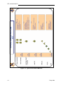
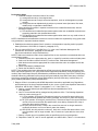
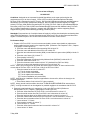
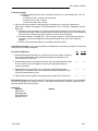
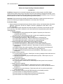
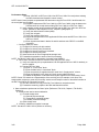
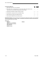
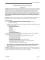
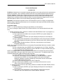
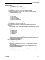
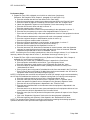
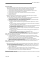
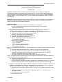
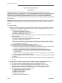
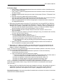
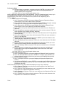
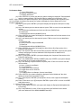
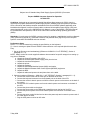
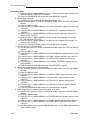
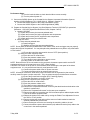
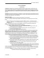
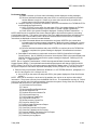
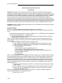
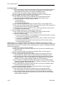
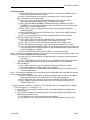
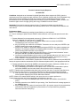
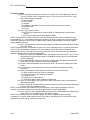
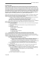
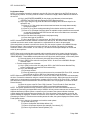
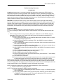
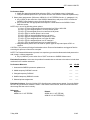
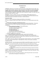
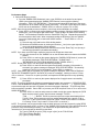
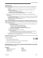
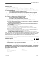
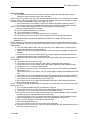
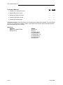
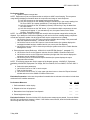
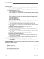
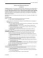
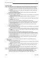
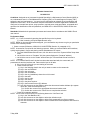
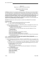
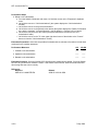
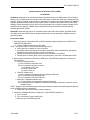
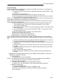
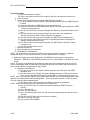
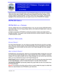
1-7.
Career Progression. The Enlisted Personnel Management System (EPMS) is the Army's overall
system to improve the professionalism of the enlisted force. It integrates policies relating to training,
evaluation, classification, and promotion into an overall system. The Soldier is provided with a means to
look to the future and see a realistic, clear, and viable career progression path from the grade of private to
that of sergeant major. However, EPMS is useless if the Soldier does not understand or use it. Part of
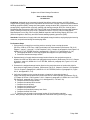
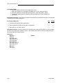
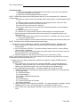
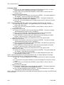
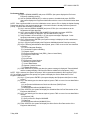
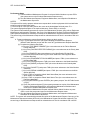
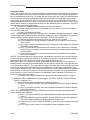
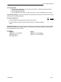
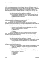
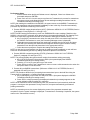
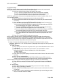
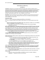
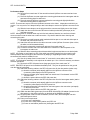
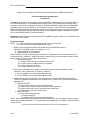
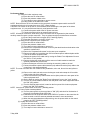
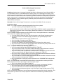
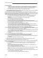
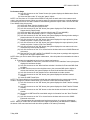
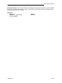
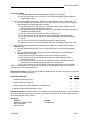
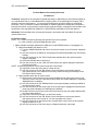
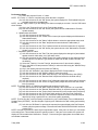
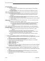
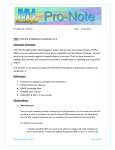
the trainer's job is to make sure the Soldier understands and uses EPMS. As an aid, Figure 1-1 provides
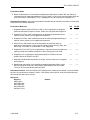
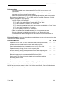
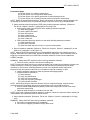
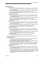
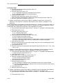
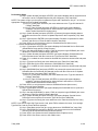
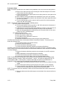
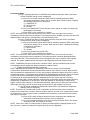
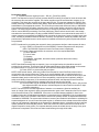
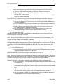
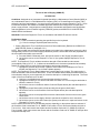
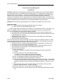
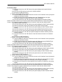
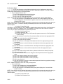
the trainer with a career map for the 92A Soldier. Figure 1-2 illustrates the typical career pattern for the
92A Soldier. The Quartermaster Center and School (QMC&S) stands ready at all times to help. If you
have a question about the ITEP or the availability of QMC&S courses, or if you need additional help in
performing your duties, you can write a letter to the QMC&S and have your questions answered. The
address is listed below:
Commander
U.S. Army Quartermaster Center and School
ATTN: ATSM-SGA
Fort Lee, VA 23801-5039
1-4
7 May 2008
STP 10-92A12-SM-TG
Figure 1-1. MOS 92A Professional Development Model
7 May 2008
1-5
STP 10-92A12-SM-TG
Figure 1-2. Typical Career Pattern MOS 92A
1-6
7 May 2008
STP 10-92A12-SM-TG
Chapter 2
Training Guide
2-1.
General. The MOS Training Plan identifies the essential components of a unit training plan for
individual training. Units have different training needs and requirements based on differences in
environment, location, equipment, dispersion, and other similar factors. Therefore, the MOS Training Plan
should be used as a guide for conducting your training and not as a rigid standard. The MOS Training
Plan has two parts to assist you in preparing a training plan that satisfies integration training requirements
for this MOS: cross train, train-up, and sustainment.
Part One of the MOS Training Plan shows the relationship of an MOS SL between duty position and
critical tasks. These critical tasks are grouped by task commonality into subject areas. Section I lists
subject area numbers and titles used throughout the MOS Training Plan. Use these subject areas to
define the training requirements for each duty position within an MOS. Section II identifies the total
training requirement for each duty position within an MOS and provides a recommendation for cross
training and train-up or merger training.
•
•
•
•
Duty Position. This column lists the duty positions of the MOS, by SL, which have different
training requirements.
Subject Area. This column lists, by numerical key (see Section I), the subject areas in which
a Soldier must be proficient to perform in that duty position.
Cross Train. This column lists the recommended duty position for which Soldiers should
cross train.
Train-Up/Merger. This column lists the corresponding duty position for the next higher skill
level or MOS the Soldier will merge into upon promotion.
Part Two lists by general subject areas the critical tasks to be trained in an MOS, the recommended
products to use, the type of training required (resident, integration, or sustainment), and a crosswalk to an
ARTEP task, as appropriate.
•
•
•
•
•
•
•
7 May 2008
Subject Area. This column lists the subject area number and title in the same order as Part
One, Section I, of the MOS Training Plan.
Task Number. This column lists the task numbers for all tasks included in the subject area.
Title. This column lists the task title for each task in the subject area.
References. This column lists required references necessary to perform and train the task.
References are listed in order of use.
Training Location. This column identifies the training location where the task is first trained to
STP standards. If the task is first trained to standard in the unit, the word “unit” will be in this
column. If the task is first trained to standard in the training base, a brevity code (for
example, BT, AIT, BNCOC, or ANCOC) will identify the resident course where the task was
taught. Figure 2-1 contains a list of training locations and their corresponding brevity codes.
Sustainment Training Frequency column. This column indicates the recommended
frequency at which you should train to ensure you maintain task proficiency. Figure 2-2
identifies the frequency codes used in this column.
Sustainment Training Skill Level column. This column lists the SLs of the MOS for which you
must receive sustainment training to ensure you maintain proficiency to SM standards.
2-1
STP 10-92A12-SM-TG
AIT
UNIT
Advanced Individual Training
Trained in the Unit
Figure 2-1. Training Locations
AN
MO
QT
SA
Annually
Monthly
Quarterly
Semiannually
Figure 2-2. Sustainment Training Frequency Codes
2-2. Subject Area Codes. Part One, Section I.
Skill Level 1
1
2
3
4
5
6
Basic Supply Principles
Basic Storage Procedures
Unit Level Logistics System-Ground/Prescribed Load List (ULLS-G/PLL)
Unit Level Logistics System-Ground/The Army Maintenance Management System
(ULLS-G/TAMMS)
Standard Army Retail Supply System (SARSS-1)
Standard Army Maintenance Management System-Enhanced (SAMS-E)
Skill Level 2
7
SAMS-E Supervisory Processes
NOTE: Subject areas 3 and 4 covering ULLS-G tasks 101-92A-1101 through 101-92A-1119 will be
phased out as more units are fielded SAMS-1E. As of 31 January 2007, these subject areas are no
longer taught in the institution and are considered unit training.
NOTE: Tasks covered in subject areas 6 and 7 are based on SAMS-1E version 12.03.01 and certain
performance steps may differ from the current operating version.
7 May 2008
2-2
STP 10-92A12-SM-TG
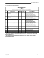
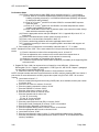
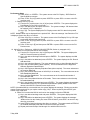
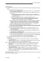
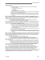
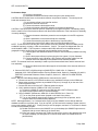
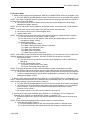
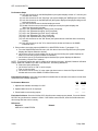
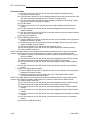
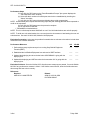
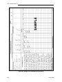
2-3. Duty Position Training Requirements.
MOS TRAINING PLAN
92A
PART ONE
SECTION II. DUTY POSITION TRAINING REQUIREMENTS
Duty Position
SL 1
Subject
Areas
1-2, 5
Cross
Train
3-4, 6-7
1-4, 6, 7
5
Materiel Handling Specialist
1-2, 5
3-4
Subsistence Supply Specialist
1-2, 5
3-4, 6-7
Materiel Control/Accounting
NCO
Equipment Records/Parts SGT
5
6, 7
6, 7
5
Materiel Storage/Handling SGT
Supply Accounting NCO
1-2, 5
1-2, 5
6, 7
6, 7
Materiel Control/Accounting
Specialist
Equipment Records/Parts
Specialist
SL2
Train-up/Merger
Materiel Control/Accounting NCO*
Supply Accounting SGT
Equipment Records/Parts SGT
Materiel Storage/Handling SGT**
Materiel Control/Accounting NCO*
Supply Accounting SGT
Equipment Records/Parts SGT
Materiel Storage/Handling SGT**
Materiel Control/Accounting NCO*
Supply Accounting SGT
Equipment Records/Parts SGT
Materiel Storage/Handling SGT**
Materiel Control/Accounting NCO*
Supply Accounting SGT
Equipment Records/Parts SGT
Materiel Storage/Handling SGT**
Equipment Records/Parts SGT
Materiel Control/Accounting NCO*
Supply Accounting SGT
Materiel Handling SGT**
Equipment Records/Parts NCO
Equipment Records/Parts NCO
* May require training for Additional Skill Identifier (ASI) G2 – Standard Army Retail Supply
System (SARSS2AC/B).
** May require training for Additional Skill Identifier (ASI) B1 – Rough Terrain Container
Handling and Operations
7 May 2008
2-3
STP 10-92A12-SM-TG
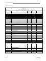
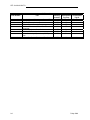
2-4. Critical Tasks List.
MOS TRAINING PLAN
MOS 92A
PART TWO: CRITICAL TASKS
Task Number
Title
Training
Location
Sustainment
Tng Freq
Sustainment
Tng SL
Skill Level 1
Subject Area 1: Basic Supply Principles
101-92A-1001
Maintain Required Publications
AIT
QT
1-2
101-92A-1002
Establish Supply and Maintenance Files
AIT
QT
1-2
101-92A-1003
Perform FEDLOG Data Inquiries
AIT
QT
1-2
101-92A-1004
Prepare Delegation of Authority Documents
AIT
QT
1-2
101-92A-1005
Receive an Item of Supply
UNIT
QT
1-2
101-92A-1006
Issue an Item of Supply
UNIT
QT
1-2
101-92A-1007
Turn-in an Item of Supply
UNIT
QT
1-2
101-92A-1008
Request an Item of Supply
UNIT
AN
1-2
101-92A-1009
Maintain a Document Register
UNIT
AN
1-2
Subject Area 2: Basic Storage Procedures
101-92A-1010
Store an Item of Supply
UNIT
QT
1-3
101-92A-1011
Perform the Proper Handling of Hazardous
AIT
QT
1-3
Materiel
101-92A-1012
Conduct an Inventory
AIT
QT
1-3
101-92A-1013
Perform Care of Supplies
AIT
QT
1-4
101-92A-1014
Operate Materiel Handling Equipment (MHE)
UNIT
MO
1-3
101-92A-1015
Perform Subsistence Supply Functions at the
AIT
MO
1-3
Ration Break Point
Subject Area 3: Unit Level Logistics System-Ground/Prescribed Load List (ULLS-G/PLL)
101-92A-1101
Maintain a Prescribed Load List
UNIT
QT
1-2
101-92A-1102
Perform Reconciliation
AIT
QT
1-3
101-92A-1103
Prepare the ULLS-G Computer System for
UNIT
QT
1-2
Operation
101-92A-1104
Process Unit Requests
UNIT
QT
1-2
101-92A-1105
Process Receipts
UNIT
QT
1-3
101-92A-1106
Perform Catalog Updates
UNIT
QT
1-3
101-92A-1107
Perform System Security Processes
UNIT
QT
1-3
101-92A-1108
Perform System Utilities Process
UNIT
QT
1-3
101-92A-1109
Initiate Continuity of Operations Plan
UNIT
QT
1-3
Subject Area 4: Unit Level Logistics System-Ground/The Army Maintenance Management System
(ULLS-G/TAMMS)
101-92A-1110
Prepare Dispatch Records
UNIT
QT
1-2
101-92A-1111
101-92A-1112
101-92A-1113
101-92A-1114
101-92A-1115
101-92A-1116
2-4
Maintain an Uncorrected Fault
Maintain a Preventive Maintenance
Schedule and Record
Prepare an Equipment Maintenance Work
Request
Prepare an Equipment Control Record
Prepare Oil Analysis Records
Perform TAMMS Functions
UNIT
UNIT
QT
QT
1-2
1-2
UNIT
QT
1-2
UNIT
UNIT
UNIT
QT
QT
QT
1-2
1-2
1-2
7 May 2008
STP 10-92A12-SM-TG
Task Number
Training Sustainment Sustainment
Location
Tng Freq
Tng SL
101-92A-1117
Process Equipment Data Updates
UNIT
QT
1-2
101-92A-1118
Perform Maintenance Support Functions
UNIT
QT
1-2
101-92A-1119
Perform Materiel Status Processes
UNIT
QT
1-2
Subject Area 5: Standard Army Retail Supply System (SARSS-1)
101-92A-1201
Prepare the SARSS Computer System for
AIT
QT
1-4
Operation
101-92A-1202
Process SARSS Data
AIT
QT
1-4
101-92A-1203
Perform System Inquiries Processes
AIT
QT
1-4
101-92A-1204
Process Materiel Release Denial and
AIT
QT
1-3
Confirmation Documents
101-92A-1205
Perform Miscellaneous Functions
AIT
QT
1-3
101-92A-1206
Process Customer Supply Requests
AIT
QT
1-3
101-92A-1207
Process Materiel Receipt Documents
AIT
QT
1-3
101-92A-1208
Operate the Materiel Release Order Control
AIT
QT
1-3
101-92A-1209
Perform Inventory Processes
AIT
QT
1-4
101-92A-1210
Update SARSS1 Parameters
AIT
QT
1-4
101-92A-1211
Perform Backup and Recovery
AIT
QT
1-3
101-92A-1212
Operate RF ID Tag
AIT
QT
1-3
101-92A-1213
Configure Communications Table
AIT
QT
1-3
Subject Area 6: Standard Army Maintenance System-Enhanced (SAMS-1E)
101-92A-1301
Perform System Setup and Operation
AIT
QT
1-2
101-92A-1302
Perform Document Control Register (DCR)
AIT
QT
1-2
Management
101-92A-1303
Turn-in an Item of Supply
AIT
QT
1-2
101-92A-1304
Receive an Item of Supply
AIT
QT
1-2
101-92A-1305
Perform Shop Supply Management
AIT
QT
1-2
101-92A-1306
Perform Catalog Management
AIT
QT
1-2
101-92A-1307
Perform Offline Supply Transactions
AIT
QT
1-2
101-92A-1308
Manage an Organizational Maintenance
AIT
QT
1-2
Work Order
101-92A-1309
Maintain Unit Equipment
AIT
QT
1-2
101-92A-1310
Perform Admin Number Management
AIT
QT
1-2
101-92A-1311
Perform Fault Management Process
AIT
QT
1-2
101-92A-1312
Perform Operator Management Processes
AIT
QT
1-2
101-92A-1313
Perform Manhour Accounting Processes
AIT
QT
1-2
101-92A-1314
Maintain Work Center Data
AIT
QT
1-2
101-92A-1315
Manage a Support Maintenance Work Order
AIT
QT
1-2
101-92A-1316
Perform AMSS Processes
AIT
QT
1-2
101-92A-1317
Perform Interface Processes
AIT
QT
1-2
101-92A-1318
Maintain Contact List
AIT
QT
1-2
101-92A-1319
Perform Backup, Restore and Purge
AIT
QT
1-2
Processes
7 May 2008
Title
2-5
STP 10-92A12-SM-TG
Skill Level 2
Task Number
Training Sustainment Sustainment
Location
Tng Freq
Tng SL
Subject Area 7: Standard Army Maintenance System-Enhanced (SAMS-1E) Supervisory Procedures
101-92A-2001
Manage System Utilities Processes
UNIT
SA
2
101-92A-2002
Perform Communications Processes
UNIT
QT
2
101-92A-2003
Perform System Security Processes
UNIT
QT
2
101-92A-2005
Perform Maintenance Master Data File
UNIT
QT
2
Processes
101-92A-2006
Maintain Equipment Class Codes
UNIT
SA
2
101-92A-2007
Maintain Unit Authorizations
UNIT
QT
2
101-92A-2009
Initiate Continuity of Operations (COOP)
UNIT
SA
2
Plan
101-92A-2010
Perform Stay Behind Equipment Transfer
UNIT
AN
2
2-6
Title
7 May 2008
STP 10-92A12-SM-TG
Chapter 3
MOS/Skill Level 10 and 20 Tasks
Skill Level 1
Subject Area 1: Basic Supply Principles
Maintain Required Publications
101-92A-1001
Conditions: Assigned as an Automated Logistical Specialist at a direct support unit (DSU) Supply
Support Activity (SSA) or at a unit motor pool and given the requirement to maintain required publications.
Given the current unit supply and maintenance files, internal standing operating procedure (SOP),
DA Pamphlet 25-30, the unit's Modified Tables of Organization and Equipment (MTOE) or Tables of
Distribution and Allowance (TDA), current DA Form 17 (Requisition for Publications and Blank Forms)
and DA Form 17-1 (Requisition for Publications and Blank Forms (Continuation Sheet)), and a computer
with internet access to the Army Publishing Directorate (APD) website.
Standards: Verified that all publications were on hand or on order for all organizational equipment listed
in the unit's MTOE or TDA using DA Pamphlet 25-30, APD website, and the internal SOP.
Performance Steps
NOTE: Click refers to the use of the computer's mouse in processing data or executing a command
within the application.
<*> = User interactively pressing the specified key on the keyboard.
[*] = Input data on to menu screen.
NOTE: Systems are already powered up to the Windows desktop display.
1. Access DA Pamphlet 25-30. (References: DA Pamphlet 25-30 website and DA Pamphlet 25-30
User's Manual, Section III).
a. Double click the left mouse button on the Internet Explorer icon on the windows desktop top
(the default homepage is displayed).
b. Use the left mouse to highlight the address line.
c. Key in http://www.apd.army.mil/ and left click the <GO> button or click <ENTER>. The APD
homepage is displayed.
d. Move the mouse cursor over the "Official Publications" to display the drop down menu.
NOTE: The arrow indicates that there are submenu options.
e. Highlight DA Pamphlet 25-30 and select the option by left clicking the mouse.
f. The system displays the Consolidated Army Publications and Forms Index screen.
2. Review and update DA Form 17 using DA Pamphlet 25-30 to search for new publications or
changes to current unit publications. (References: DA Pamphlet 25-30 website and
DA Pamphlet 25-30 User's Manual, Section III, V, and VI).
a. Review DA Form 17 against the DA Pamphlet 25-30 for changes to current unit publications.
(1) Use the "Quick Search" method.
(2) Click on the "Search Field" down arrow to display the search field options. Discuss the
drop down window options.
(3) Click the Pub/Form Number option.
(4) Press <TAB> or click in the "Search for Field" to advance the cursor.
(5) Key in the publication number and left click the "Submit" button. The system displays the
search results in a different window.
NOTE: Continue this process until all publications and forms listed in column "b" on the unit's
DA Form 17 and DA Form 17-1 are reviewed.
(6) Annotate publication change data on DA Form 17.
7 May 2008
3-1
STP 10-92A12-SM-TG
Performance Steps
b. Search DA Pamphlet 25-30 using the line item number (LIN) found on the MTOE/TDA for
publications on new equipment
(1) Click the "Advanced Search" option. The system displays the various fields to use for an
advanced search.
INSTRUCTOR NOTE: Discuss the various fields used in this search option.
(2) Locate LIN on MTOE/TDA.
(3) Enter a single LIN and click the "Submit" button.
NOTE: The search may also be performed using national stock numbers (NSNs).
(4) The system displays all the available publication information for that LIN.
(5) Close the search results window to enter information for a new search.
NOTE: Continue this process until a search for publications and forms for new equipment is complete.
(6) Click the "Back" button to return to the Consolidated Army Publications and Forms Index.
3. Prepare a DA Form 17 to update the unit's publications list and obtain new publications.
(References: DA Pamphlet 25-30 website, DA Pamphlet 25-33, paragraph 3-3, and the unit internal
SOP).
a. Enter the header information.
(1) Enter the page number and total number of pages in "page__ of __ pages" block.
(2) Enter the current date in "Date of Requisition" block.
(3) Enter the name of requisitioning agency in the "Name of Requisitioning Agency" block,
Leave blank if same as "ship to" address in block "6".
(4) Enter the assigned account number in "Account No" block (if applicable).
(5) Leave blank "Requisition number" block.
b. Enter the requisitioning information on the form.
(1) Check type of requisition, "regular" or "special" in block "1".
(2) Enter justification for special requisition in block "2".
(3) Enter required date (use Julian date) in block "3".
(4) Check appropriate box (if applicable) in block "4".
(5) Enter the address of the agency to which the request is forwarded to in block "5".
(6) Enter the ship to address in block "6".
NOTE: Group publications or forms into categories, such as Army Regulations, DA Pamphlets, Field
Manuals, DA Forms, DD Form, and so on. List the items in numerical sequence within each category (for
example AR 10-5 and AR 380-5). Use a separate line for each item in block "7". Use DA Form 17-1 as a
continuation sheet when required.
(7) Enter the unit requirements in block "7".
(a) List line item number starting with 1 in sequence regardless of category in column
"a".
(b) Enter numerical designation (or title if unnumbered) of the item in column "b".
NOTE: When ordering publications, order as follows:
1. AR 10-1 (when only the basic publication is desired).
2. AR 10-1 and changes (when a basic publication including all current changes is desired).
3. AR 10-1, C1 (when a specific change(s) is desired).
(c) Enter the unit of issue (for forms only) in column "c".
(d) Enter the quantity requested in column "d".
(8) Type the name and grade of the commanding officer, adjutant, publication, or property
officer and obtain signature in block "8".
(9) Leave blank blocks number "9 - 17".
4. Forward DA Form 17 and DA Form 17-1 to the unit publication clerk. (References:
DA Pamphlet 25-30 website; DA Pamphlet 25-33, Chapter 3, paragraph 3-10; and the unit internal
SOP).
3-2
7 May 2008
STP 10-92A12-SM-TG
Performance Steps
5. File unit copies of DA Form 17 and DA Form 17-1 in the unit's Publication Management file.
(References: AR 25-400-2, Chapter 6, paragraph 6-1 and website
ttp://www.rmda.belvoir.army.mil/markstit.htm).
a. Select unit file folder numbered 25-30hh, "Publications and Forms Requisitions."
b. Place all approved or revised DA Form 17 and DA Form 17-1 forms into the unit publication
management file folder.
c. Remove and destroy outdated forms.
d. Return the file folder to unit files.
NOTE: These websites have been designated as official Army sites for departmental publications and
forms: https://akocomm.us.army.mil/uspap/ (AKO; all departmental publications, to include distribution
restricted items), http://www.army.mil/usapa/index.html (Army homepage; all unrestricted departmental
publications and forms), https://www.logsa.army.mil (Army technical and equipment publications (except
engineering and medical), http://www.apd.army.mil (Administrative publications and forms),
http://www.atsc.army.mil (Army doctrinal and training publications (except engineering and medical),
http://www.usace.army.mil/usace-docs/ (Army engineering publications (except administrative) and
http://www.armymedicine.army.mil/default2.htm (Army medical publications (except administrative). For
Department of Defense forms, access
http://www.dtic.mil/whs/directives/infomgt/forms/formsprogram.htm.
Evaluation Preparation: At the test site provide all materials that are relevant to the task to include those
mentioned in the condition statement.
Performance Measures
GO
NO-GO
1. Accessed DA Pamphlet 25-30.
——
——
2. Reviewed and updated DA Form 17 using DA Pamphlet 25-30 website to search
for new publications or changes to current unit publications.
——
——
3. Prepared a DA Form 17 to update the unit's publications list and obtain new
publications.
——
——
4. Forwarded DA Form 17 and DA Form 17-1 to the unit publication clerk.
——
——
5. Filed unit copies of DA Form 17 and DA Form 17-1 in the unit's Publication
Information Management file.
——
——
Evaluation Guidance: Score the Soldier GO if all performance measures are passed. Score the Soldier
NO-GO if any performance measure is failed. If the Soldier scores NO-GO, show the Soldier what was
done wrong and how to do it correctly.
References
Required
AR 25-400-2
DA FORM 17
DA FORM 17-1
DA PAM 25-30
DA PAM 25-33
7 May 2008
Related
AR 25-30
DA PAM 710-2-1
DA PAM 710-2-2
LOCAL SOP
3-3
STP 10-92A12-SM-TG
Establish Supply and Maintenance Files
101-92A-1002
Conditions: Assigned as an Automated Logistical Specialist at a direct support unit (DSU) Supply
Support Activity (SSA) or at a unit motor pool and given the requirement to establish supply and
maintenance files. Given the current unit supply and maintenance files and local standing operating
procedures (SOPs), AR 25-400-2, a file cabinet and file folders, blank labels, file guides, pen/typewriter,
and a computer with access to the Internet.
Standards: Establish unit supply and maintenance files in accordance with AR 25-400-2.
Performance Steps
1. Determine the files required to be maintained in accordance with AR 25-400-2. (Reference:
AR 25-400-2, paragraphs 2-1 and 3-1).
a. Access the Army Records Information Management System (ARIMS).
(1) Double click the left mouse button on the Internet Explorer icon on the Windows desktop,
the system default home page is displayed.
(2) Place the mouse cursor anywhere in the <http://> address line and left click the mouse
button (the data in the address line is highlighted) or press the <TAB> key (provided you
have not clicked another place on the Web page), to highlight the address line.
(3) Key in [http://www.arims.army.mil/] and press the <ENTER> key or place the mouse
cursor over the <GO> button and left click the mouse button (a security alert message
maybe displayed).
NOTE: In some instances a security alert message may appear. Read the message, left click the <OK>
button to proceed.
(4) If you receive the security alert message, read and left click the <YES> button. The
ARIMS disclaimer page is displayed
(5) Read the ARIMS disclaimer message then left click on the link at the bottom of the page
to proceed to the ARIMS.army.mil homepage.
NOTE: The ARIMS homepage appears with seven tab folders at the top of the screen. The Home tab
shows red letters on a white tab signifying the folder is active.
b. Generate files description information.
(1) Place the cursor over the Records Retention Schedule-Army (RRS-A) tab. The cursor
turns into a pointing hand and the white letters change to green.
(2) Click the left mouse button on the RRS-A tab. A search screen appears and the RRS-A
tab is now the active folder.
NOTE: This screen shows a search box (use the vertical scroll bar to the far right of the screen to view
the full screen) with four gray arrows indicating search options. There are three basic search options:
Search by Keyword; Search by Army Regulation or other prescribing directive, and Browse by Record
Category. The Select Type of Record option is used with the three basic options. Explain each option
and type record selection options.
(3) Point the mouse cursor in the box directly below the "Search by Army Regulation or other
prescribing directive" and left click the mouse button.
(4) Key in the applicable regulation or prescribing directive then select the "Type of Records"
option.
(5) Click the left mouse button on the "Submit Search" button (depending on the search
criteria and the Type of Record options selected, the system displays the search display
screen consisting of all records for the specified search).
NOTE: When you are not sure of the type of record selection option, it is best to select "ALL" for each
category listed. This will retrieve all information concerning the regulation or directive, which was used in
the search.
3-4
7 May 2008
STP 10-92A12-SM-TG
Performance Steps
c. Print file description information.
(1) Place the mouse cursor over the desired record listed in the "REC CATEGORY" column
and click the left mouse button (the system displays the complete file description and filing
instructions for the selected file).
(2) Place the mouse cursor over the <<PRINT>> option located at the top of the file
information and click the left mouse button to print the file description information.
NOTE: After printing the file description information, select one of the following options to continue:
<<BACK TO LIST>>, <<NEW SEARCH>>; <<PRINT>>; <<PREVIOUS>>; or <<NEXT>> to obtain record
information for the desired records information. Do not destroy this printed information, it will be used
later to develop your Office Records List (ORL).
(3) Place the cursor over the <<BACK TO LIST>> option located at the top of the file
information and click the left mouse button. The system returns to the search results
screen.
(4) Select the next desired "Record Category" to obtain file description and filing instructions.
NOTE: Repeat sub-step "c" as often as required until all record information regarding supply and
maintenance records has been obtained.
d. Close the ARIMS application.
(1) Place the mouse cursor over the "File" command located on the Internet browser tool bar
and left click the mouse button. The system displays the drop down menu.
(2) Click on "Close" (the Internet browser will close).
2. Prepare an Office Records List (ORL) for all required supply and maintenance files without Records
Manager-Assist (RM-Assist). (Reference: AR 25-400-2, paragraph 5-10 and Table 5-1).
NOTE: Use the file description information printed in the previous performance step to extract the
required data to prepare an ORL. ORLs are required and are prepared using the RM-Assist in ARIMS,
when the user has a registered account with ARIMS. ORLs prepared without RM-Assist should include
at a minimum the ARIMS record titles, disposition codes, and the Privacy Act (PA) system numbers, if
applicable.
a. Prepare the ORL containing the following information:
(1) Record Category.
(2) Record Title.
(3) Record Type (Keep (K) or Transfer (T)).
(4) Duration.
(5) Permanent.
(6) Disposition Authority.
(7) Privacy Act (PA) Number.
(8) Record Number.
(9) Status.
b. Update the list as file numbers are added or deleted.
c. File the list.
3. Prepare file folder labels using ARIMS file labeling format. (Reference: AR 25-400-2, Chapter 6,
paragraph 6-2 and Figure 6-1).
NOTE: All folders and containers used to store official records will be labeled. The office of record may
label these folders and containers in any manner that best suits the business needs of an office. This
includes anything from typewritten or computer generated labels to writing or printing directly on the
folders or containers with colored pens and markers.
a. Print or type on each label the disposition instruction standards (record type "K" or "T").
(1) File number
(2) All records are divided into two categories: Transfer (T) records and Keep (K) records.
The transfer records are saved beyond their usefulness as business records and keep
records are saved only to serve the business needs.
7 May 2008
3-5
STP 10-92A12-SM-TG
Performance Steps
(3) Use "K" for records that will be managed entirely within the office. The following
disposition codes are under record type "K".
(a) K (Time periods .25 through 6): Records are kept in the current files area until the
time period specified has passed, then destroy (example: K3, keep for 3 years then
destroy).
(b) KE (Time periods .25 through 6, plus the event): Records are kept in the current files
area until the event occurs and then the specified time, then destroy (example: KE4,
keep 4 years after the event then destroy).
(c) KN (time period not known): Keep in the current files area until no longer needed for
conducting business, but no more than 6 years, then destroy.
(d) KEN (Event, but time period is not known): Keep in the current files area until the
event occurs and then until no longer needed. However, no more than 6 years after
the event, then destroy.
(4) Privacy Act system notice number (if applicable)
(5) Disposition Codes "R" and "S" are not applicable, see AR 25-400-2, Table 7-1 for
instructions.
(6) Use "T" for records that will be transferred to a Records Holding Area (RHA) or Army
Electronic Archives (AEA).
(7) Disposition instructions
(a) T (Time periods over 6 years): Keep in the current files area until no longer needed;
then retire to the AEA and/or RHA (example: T10.25, keep for 10 years and 3
months then retire to AEA and/or RHA).
(b) TE (Time periods over 6 years plus event): Transfer to AEA and/or RHA after a
specific event occurs.
(c) TEP (Transfer to AEA and/or RHA after a specific event occurs).
(d) TP (Transfer permanent): Keep in the current files until no longer needed, then retire
to AEA and/or RHA.
(8) Year of accumulation (if applicable)
(9) U (Unscheduled record): Retain in current files area until disposition instructions are
published, then apply the approved disposition.
NOTE: Disposition instructions are found in AR 25-400-2, Chapter 7, Table 7-1.
b. Print or type on each label the record title.
c. Print or type on each label the PA number (if applicable).
d. Print or type on each label the year of creation.
4. File records in file cabinet using file folders. (References: AR 25-400-2, Chapter 5, paragraphs 5-2
through 5-4, 5-7, 5-9, and 5-10 and AR 380-5, Chapter 2, paragraph 2-10).
a. Use guides to divide records and identify subdivisions.
b. Use folders to consolidate, retrieve, and protect records.
c. Arrange the records in an orderly manner that best suits the business or reference needs.
(1) Arrange documents by chronological date.
(2) Arrange documents in simple numerical sequence, such as unit designation or project
number.
(3) Arrange documents alphabetically by subject or personal name (last name, first name,
and middle initial) or organization identification.
d. Mark or stamp all folders with the proper classification per AR 380-5.
e. File classified and unclassified documents separately; using guide cards or placement in
separate drawers.
f. Secure classified records and containers.
NOTE: Records not covered by a Privacy Act (PA) System Notice will not be arranged to permit retrieval
by personal identifier (that is, name, social security number, date of birth). Only records covered by the
system notices published in DA Pamphlet 25-51, The Army Privacy Program-System or Records Notices
and Exemption Rules may be arranged for retrieval by personal identifier.
g. Stamp the file folder with the required classification in accordance with AR 380-5.
3-6
7 May 2008
STP 10-92A12-SM-TG
Performance Steps
h. Subdivide multiple documents under a file number.
(1) Arrange documents by chronological date.
(2) Arrange documents in simple numerical sequence, such as unit designation or project
number.
(3) Arrange documents alphabetically by subject or personal name (last name, first name,
middle initial) or organization identification.
i. Place classified documents in separate containers from unclassified documents, with the
following exceptions:
(1) File classified and unclassified documents together when the unclassified documents are
supporting material to the classified documents.
(2) File classified and unclassified documents together when there is a very small volume of
classified documents.
NOTE: Classified and unclassified documents in the same container are separated by using guide cards
or by placement in separate container drawers.
5. Establish and maintain suspense files for records or correspondence requiring action by specific
dates. (Reference: AR 25-400-2, Chapter 5, paragraph 5-12).
6. File unit copies of DA Form 17 and DA Form 17-1 in the unit's Publication Management file.
(References: AR 25-400-2, paragraph 6-1and website
http://www.rmda.belvoir.army.mil/markstit.htm).
NOTE: Folders and containers used to keep suspense files are not required to be maintained within the
record keeping system.
a. Place documents in the appropriate day, week, or month file in which the action will take place.
b. Select unit file folder numbered 25-30d, "Functional Files, Publication Management."
c. Mark the document with the appropriate file number when the action is complete and file the
document.
d. Remove and destroy outdated forms.
e. Return the file folder to unit files.
NOTE: These websites have been designated as official Army sites for departmental publications and
forms: http://www.logsa.army.mil (Army technical and equipment publications (except engineering and
medical), http://www.usapa.army.mil (Administrative publications and forms), http://155.217.58.58 (Army
doctrinal and training publications (except engineering and medical), http://www.usace.army.mil/usacedocs (Army engineering publications (except administrative) and http://www.army medicine.army.mil
(Army medical publications (except administrative).
7. Dispose of files in accordance with ARIMS disposition instructions, applicable Army Regulations,
and Department of the Army Pamphlets based on time, event, or time-event disposition instructions.
(Reference: AR 25-400-2, Chapter 7, paragraphs 7-1 to 7-3 and Table 7-1).
a. Destroy a record following the specified time after the established cut off for
time disposition.
b. Use "K" for records that will be managed entirely within the office. The following disposition
codes are under record type "K".
(1) K (Time periods .25 through 6): Records are kept in the current files area until the time
period specified has passed, then destroy (example: K3, keep for 3 years then destroy).
(2) KE (Time periods .25 through 6, plus the event): Records are kept in the current files area
until the event occurs and then the specified time, then destroy (example: KE4, keep 4
years after the event then destroy).
(3) KN (time period not known): Keep in the current files area until no longer needed for
conducting business, but no more than 6 years, then destroy.
(4) KEN (Event, but time period is not known): Keep in the current files area until the event
occurs and then until no longer needed , but no more than 6 years after the event, then
destroy.
c. Destroy a record upon or immediately after the specified event for event disposition.
d. Disposition Codes "R" and "S" are not applicable, see AR 25-400-2, Table 7-1 for instructions.
7 May 2008
3-7
STP 10-92A12-SM-TG
Performance Steps
e. Destroy a record at a specified period of time after an event takes place.
f. Use "T" for records that will be transferred to a Records Holding Area (RHA) or Army Electronic
Archives (AEA).
(1) T (Time periods over 6 years): Keep in the current files area until no longer needed, then
retire to the AEA and/or RHA (example: T10.25, keep for 10 years and 3 months then
retire to AEA and/or RHA).
(2) TE (Time periods over 6 years plus event): Transfer to AEA and/or RHA after a specific
event occurs.
(3) TEP (Transfer to AEA and/or RHA after a specific event occurs).
(4) TP (Transfer permanent): Keep in the current files until no longer needed, then retire to
AEA and/or RHA.
g. U (Unscheduled record): Retain in current files area until disposition instructions are published;
then apply the approved disposition.
NOTE: Disposition instructions are found in AR 25-400-2, Chapter 7, Table 7-1.
Evaluation Preparation: At the test site provide all materials that are relevant to the task to include those
mentioned in the condition statement.
Performance Measures
GO
NO-GO
1. Determined the files required to be maintained in accordance with AR 25-400-2.
——
——
2. Prepared an Office Records List (ORL).
——
——
3. Prepared file folder labels using the ARIMS file-labeling format.
——
——
4. Filed records in file cabinet using file folders.
——
——
5. Established and maintained suspense files for records or correspondence
requiring action by specific dates.
——
——
6. Filed unit copies of DA Form 17 and DA Form 17-1 in the unit's Publication
Management file.
——
——
7. Disposed of files in accordance with the ARIMS disposition instructions,
applicable Army Regulations, and Department of the Army Pamphlets based on
time, event, or time-event disposition instructions.
——
——
Evaluation Guidance: Score the Soldier GO if all performance measures are passed. Score the Soldier
NO-GO if any performance measure is failed. If the Soldier scores NO-GO, show the Soldier what was
done wrong and how to do it correctly.
References
Required
AR 25-400-2
AR 380-5
DA FORM 17
DA FORM 17-1
3-8
Related
AR 710-2
DA PAM 710-2-1
DA PAM 750-8
LOCAL SOP
7 May 2008
STP 10-92A12-SM-TG
Perform FEDLOG Data Inquiries
101-92A-1003
Conditions: Assigned as an Automated Logistics Specialist at a direct support unit (DSU) Supply
Support Activity (SSA) or a unit's motor pool and given the requirement to use Federal Logistics
(FEDLOG) CD-ROM. Given a desk top computer with current edition of FEDLOG installed, access and
perform interactive queries using the Army and Federal Logistics Information System (FLIS) Dataviews.
Standards: Operated and performed Army and FLIS interactive query using FEDLOG to obtain correct
data in accordance with FEDLOG User Manual.
Performance Steps
NOTE: Click refers to the use of the computer mouse in processing data or executing a command.
<*> = User interactively pressing the specified key on the keyboard.
[*] = Input data on to menu screen.
1. Access FEDLOG from a windows desktop computer. (Reference: FEDLOG User Manual).
a. Left click on "Start" menu.
b. Select "Programs".
c. Select "FEDLOG".
d. Select and left click on "FEDLOG Interactive", the system advances to the Interactive menu.
NOTE: FEDLOG may also be accessed by double clicking on the FEDLOG desktop icon that was
automatically created during the installation procedures.
CAUTION: When loading or updating FEDLOG, the user may be prompted with a message asking "Do
you want to read the latest information from Defense Logistics Information System (DLIS) about
FEDLOG?" Left click on "YES" to read or left click on "NO" not to read it.
2. Identify the interactive base screen menus, shortcuts keys, and toolbar icons available using
FEDLOG. (References: FEDLOG CD-ROM and FEDLOG User Manual).
NOTE: In the base screen view, select commands that are not active because no data has been entered
into the query screen. Left click on each menu bar title to see the options listed on each drop down
menu.
a. Identify File menu commands and shortcut keys.
(1) Print or <Ctrl + P> (prints information displayed in the dialog box, available only if a search
has been made and data is displayed).
(2) Print Setup (allows for choosing a printer and printer settings).
(3) Properties or <Alt + Enter> (lets you to set basic search and display properties).
(4) Exit or <Alt + F4 > (closes the FEDLOG program).
b. Identify Edit menu commands and shortcut keys.
(1) Copy Window or <Ctrl + C> (copies the information currently on screen to the clipboard to
paste into another application).
(2) Copy View or <Ctrl + D> (copies all the information in a view, even if all of it is not
displayed on screen to the paste buffer).
(3) Select Copy (copies the highlighted text on the screen to the clipboard).
(4) Headers (a toggle switch to print headers to the copied file, or just the data).
(5) Find or <Ctrl + F> and Find Next or <Ctrl + G> (a search tool used to search through a
selected list).
c. Identify Service menu commands, shortcut keys and toolbar icons.
(1) Service Filter… or <F6> (provides the option of limiting searches based on service).
(2) Service Query Options:
(a) FLIS (toolbar icon = FLIS).
(b) Air Force (toolbar icon = airplane).
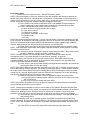
(c) Army (toolbar icon = tank).
(d) Marine Corps (toolbar icon = globe and anchor).
(e) Navy (toolbar icon = anchor).
7 May 2008
3-9
STP 10-92A12-SM-TG
Performance Steps
d. Identify Dataviews menu commands and shortcut keys.
(1) Select Views or <F3> (opens a dialog box that allows for the selection of specific
Dataviews).
(2) Next View or <Ctrl+ Right (arrow key)> (brings up the next Dataview as defined in the
"Select Views" list).
(3) Previous View or <Ctrl+ left (arrow key)> (brings up the previous Dataview as defined in
the "Select Views" list).
(4) Federal Logistics Information System (FLIS), Air Force, Army, Marines, or Navy (activates
a fly-out menu listing all the Dataviews available for each service for the current search
result).
e. Identify View menu commands and shortcut keys.
(1) Sale List (list discounted items program sale list).
(2) Environmentally Preferred Item List (list of supplies used by the government that have
environmental characteristics).
(3) Army (brings up a submenu that lists Army publication and data files relating to logistics
information).
(4) Standard Supply Numbering System (SSNS) (displays a cross reference relationship of
Line Item Numbers (LINs), Department of Defense Activity Address Codes (DODAACs),
and associated national stock numbers (NSNs) to a series of SSNS).
(5) Toolbar (toggle switch to view or hide the FEDLOG toolbar).
(6) Status Bar (toggle switch to view or hide the FEDLOG status bar).
(7) Next Section or press <Alt + N> (moves to either the next Dataviews or the next category
of the Item Name pick list).
(8) Previous Section or <Alt + P> (moves to either the previous Dataviews or the previous
section of the Item Name pick list).
NOTE: The options located on the Help menu give easy access to information about the FEDLOG
program, data, and service-specific programs. This menu also provides access to the user's manual and
FEDLOG tutorial.
3. Identify query screen buttons used with Army interactive query screen. (Reference: FEDLOG User
Manual).
a. NIIN/NSN (national item identification number/national stock number).
b. Federal supply class (FSC).
c. Part Number.
d. Item Name (nomenclature).
e. Item Name Code (INC).
f. Supplier Name.
g. Army, Standard Army Retail Supply System Catalog (SARSSCAT) Data.
h. Army Master Data File (AMDF) Hazardous Material.
i. AMDF Related NSN Data.
j. Characteristics Data.
k. Representative Drawings Data.
l. Custom View.
4. Perform an interactive search for a NIIN/NSN using the Army Interactive Query screen. (References:
FEDLOG CD-ROM and FEDLOG User Manual).
a. Left click on the "Army" icon on the toolbar or left click on "Service" on the menu bar and left
click on "Army".
b. Enter the criteria to be queried in the NIIN/NSN query field and left click on "Search".
NOTE: When the FEDLOG application provides a response to the queried information, it is populated on
the screen. Other queries maybe performed using any of the other query fields. Queries are also
performed by left clicking on the query screen buttons. A browse dialog will appear showing the multiple
values to be selected. You may either type the query into fields or choose a value from the current item.
This Dataview is available in the AMDF Management Dataview.
3-10
7 May 2008
STP 10-92A12-SM-TG
Performance Steps
c. Select Army Dataview.
(1) Left click on "Dataviews" on the menu bar.
(2) Select and left click on the "Select Views" option or press <F3>, a "Select Views" dialog
box opens that allows for the selection of specific Dataviews:
(a) Army Master Data File (AMDF) Management Data.
(b) Reference Number Data.
(c) Freight Data.
(d) Supplier Data.
(e) AMDF Packaging Data.
(f) History Data.
(g) Army, Standard Army Retail Supply system Catalog (SARSSCAT) Data.
(h) AMDF Hazardous Materiel.
(i) AMDF Related NSN Data.
(j) Characteristics Data.
(k) Representative Drawings Data.
(l) Custom View.
NOTE: Once the Dataviews have been selected and the query response screen returns, use the "Next
View" or "Previous View" arrows located on the toolbar menu as shortcuts to the various Dataviews. The
Interchangeability and Substitutability (I&S) Dataview button displays I&S view for the current item. This
Dataview is available in the AMDF Management Dataview.
5. Start a new search using the FLIS interactive query screen.
a. Click the left mouse button on "New Search".
b. Click the left mouse button on "Clear All" to clear data from the query screen.
c. Left click on the "FLIS" icon on the toolbar or left click on "Service" on the menu bar and left
click on "FLIS".
6. Identify query screen buttons used with FLIS interactive query screen. (References: FEDLOG CDROM and FEDLOG User Manual).
a. NIIN/NSN (national item identification number/national stock number).
b. FSC (federal supply class).
c. Part Number.
d. Item Name (nomenclature).
e. INC (item name code).
f. Supplier Name.
g. Source of supply.
h. Commercial and government entity (CAGE) code.
i. Characteristics.
7. Perform an interactive search for a Part Number using the FLIS Interactive Query screen.
(Reference: FEDLOG CD-ROM).
a. Enter the criteria to be queried in the Part Number query field and left click on "Search".
NOTE: When the FEDLOG application provides a response to the queried information, it is populated on
the screen. Other queries may be performed using any of the other query fields. Queries are also
performed by left clicking on the query screen buttons. A browse dialog will appear showing the multiple
values to be selected. You may either type the query into fields or choose a value from the browse list.
b. Select FLIS Dataviews.
(1) Left click on "Dataviews".
(2) Select and left click on "Select Views" or press <F3> (opens a dialog box that allows for
choice of Dataviews displayed):
(a) History Data.
(b) Management Data.
(c) Reference Number Data.
(d) Freight Data.
(e) Supplier Data.
7 May 2008
3-11
STP 10-92A12-SM-TG
Performance Steps
(f) Characteristics Data.
(g) Representative Drawings Data.
(h) Custom View.
NOTE: Once the Dataviews have been selected and the query response screen returns, use the Next
View or Previous View arrows located on the toolbar menu as shortcuts to the various Dataviews.
Evaluation Preparation: At the test site provide all materials that are relevant to the task to include those
mentioned in the condition statement.
Performance Measures
GO
NO-GO
1. Accessed FEDLOG from a windows desktop computer.
——
——
2. Identified the interactive base screen menus, shortcuts keys and toolbar icons
available using FEDLOG.
——
——
3. Identified query screen buttons used with Army interactive screen query.
——
——
4. Performed interactive search for a NIIN/NSN using the Army interactive query
screen.
——
——
5. Started a new search using the FLIS interactive query screen.
——
——
6. Identified query screen buttons used with FLIS interactive query.
——
——
7. Performed interactive search for a Part Number using FLIS interactive query
screen.
——
——
Evaluation Guidance: Score the Soldier GO if all performance measures are passed. Score the Soldier
NO-GO if any performance measure is failed. If the Soldier scores NO-GO, show the Soldier what was
done wrong and how to do it correctly.
References
Required
FEDLOG
3-12
Related
7 May 2008
STP 10-92A12-SM-TG
Prepare Delegation of Authority Documents
101-92A-1004
Conditions: Assigned as an Automated Logistical Specialist at a direct support unit (DSU) Supply
Support Activity (SSA) or a unit motor pool and given the requirement to prepare delegation of authority
documents. Given blank DA Form 1687 (Notice of Delegation of Authority - Receipt for Supplies), a blank
DA Form 5977 (Authorization Card), a blank DA Form 5978 (Control Sheet), assumption of command
orders or appointment memorandum, unit Modified Table of Organization and Equipment (MTOE) or
Tables of Distribution and Allowances (TDA), internal and external standing operating procedure (SOP),
ink pen/typewriter, and names of designated unit representatives.
Standards: Prepared delegation of authority documents that established authorization to request,
receive, and/or turn-in supplies and equipment.
Performance Steps
1. Prepare sufficient copies of DA Form 1687 (in ink or typewritten) to designate personnel authorized
to request, receive, and/or turn-in supplies and equipment. (Reference: DA Pamphlet 710-2-1,
Chapter 2, Section V, paragraph 2-32, Figure 2-14).
a. Enter the calendar date the form is prepared in the "Date" block.
b. Enter the unit name in the "Organization Receiving Supplies" block.
c. Enter the name of the unit's installation in the "Location" block.
d. Enter the name of authorized each representative(s) in the "Last Name-First Name-Middle
Initial" block.
(1) Prepare a continuation card if more than four authorized representatives are required.
(2) Enter the statement "Continuation to DA Form 1687 dated…" in the "Remarks" block of
the follow-on card.
(3) Enter "not used" on the next name line when all the name lines are not used.
e. Enter "yes" or "no" in the "Authority REQ/REC" block, as applicable, for each authorized
representative.
f. Obtain the signature and initial of each authorized representative in the "Signature/Initials"
block.
g. Enter an "X" in the "Delegates To" authorization box to show that the authorized representative
is delegated to request/receive supplies.
h. Print or type the statement to indicate the classes of supplies for which the representative may
sign.
i. Enter the SSA or other supporting activity in the "Remarks" block.
j. Enter the assigned unit identification code (UIC) in the "UIC" block.
k. Enter the Department of Defense Activity Address Code (DODAAC) or any locally assigned
account number in the "DODAAC/Account Number" block.
l. Enter the name of the accountable/responsible officer (last name, first name, and middle initial)
in the "Name" block.
m. Enter the grade of the responsible officer in the "Grade" block.
n. Enter the telephone number in the "Telephone" block.
o. Enter the expiration date in the "Expiration date" block.
p. Obtain the unit commander's or other designated unit responsible person's signature.
2. Prepare DA Form 1687 to add personnel as authorized representatives to request, receive, and/or
turn-in supplies and equipment. (Reference: DA Pamphlet 710-2-1, Chapter 2, Section V, paragraph
2-32 and Figure 2-14).
NOTE: Prepare the card in the same manner as the original authorization card with following exception.
a. Enter the name(s) of the new authorized representative(s) in the "Last Name-First NameMiddle Initial" block.
b. Enter the statement "Added, previous editions remain in effect" in the "Remarks" block.
c. Obtain signature(s) and initial(s) of the new authorized representative(s).
7 May 2008
3-13
STP 10-92A12-SM-TG
Performance Steps
3. Prepare DA Form 1687 to delete personnel as authorized representative(s) to request, receive,
and/or turn-in supplies and equipment. (Reference: DA Pamphlet 710-2-1, Chapter 2, Section V,
paragraph 2-32 and Figure 2-14).
NOTE: Prepare the card in the same manner as the original authorization card with following exception.
a. Enter the name(s) of the authorized representative(s) deleted in the "Last Name-First NameMiddle Initial" block.
b. Enter an "X" in the "withdraws from" box and then circle the box with colored pencil or ink.
c. Enter the statement "Deleted, other person(s) listed remain in effect" in the "Remarks" block.
NOTE: Do not obtain signatures of deleted representative(s).
4. Send DA Form 1687 (new, added, or deleted), together with a copy of the assumption of command
orders or appointment memorandum, to the supporting Supply Support Activity (SSA), and file a
copy, with orders or memorandum, in unit supply files. (References: DA Pamphlet 710-2-1,
Chapter 2, paragraph 2-32 and AR 25-400-2, Chapter 5, paragraph 5-4).
5. Prepare DA Form 5977 (in ink or typewritten) to request and receipt for supplies not requiring formal
accountability at the organizational level. (References: DA Pamphlet 710-2-1, paragraph 2-32,
Figure 2-21 and AR 25-400-2, Chapter 5, paragraph 5-4).
a. Enter the unit or activity designation in the "Organization, Installation" block.
b. Enter the unit DODAAC in the "DODAAC/Account #" block.
c. Enter the signature block (name, grade, branch, and the word "commanding") of the
accountable/responsible officer in the "signature" block.
d. Obtain the signature of the responsible/accountable officer in the "signature" block.
e. Enter the serial number in the "Serial Number" block, using the serial number from
DA Form 5978.
f. Enter (reverse side) an "X" in one or more of the appropriate "Authorized Facilities" boxes to
which authorization is granted by the responsible/accountable officer.
NOTE: To avoid misuse of authorization cards, commanders/accountable officers/responsible officers are
discouraged from checking every box on the back of the card.
6. Prepare (in ink or typewritten) and maintain DA Form 5978 to track the location and use of the
DA Form 5977. (References: DA Pamphlet 710-2-1, Chapter 2, paragraph 2-32 and AR 25-400-2,
Chapter 5, paragraph 5-4 and Figure 2-22).
a. Enter the serial numbers in the "Serial Number" column.
NOTE: The commander/accountable officer/responsible officer develops and controls the serial number
list.
b. Enter an "X" in each appropriate box that corresponds to the facility that will be entered on the
back of the DA Form 5977.
c. Enter the name (in ink) of the card holder and obtain their signature in the "Holder" column.
7. Dispose of Authorization documents to request, receive and/or turn-in supplies and equipment.
(References: DA Pamphlet 710-2-1, paragraph 2-32 and AR 25-400-2, paragraph 3-1).
NOTE: Prior to disposing of authorization documents ensure that new documents are prepared for
signature of the incoming commander, accountable officer, or responsible officer.
a. Collect and dispose of DA Form 1687:
(1) At the change of command.
(2) At the change of Accountable Officer.
(3) At the change of Responsible Officer.
b. Collect and dispose of DA Form 5977:
(1) At the change of command.
(2) At the change of Accountable Officer.
(3) At the change of Responsible Officer.
c. Retain the old DA Form 5978 in active supply administration files (file number 710-2i) for one
year and destroy in after two years.
3-14
7 May 2008
STP 10-92A12-SM-TG
Performance Steps
8. Retain old assumption of command/accountable/responsible officer's orders after the change of
command in active supply administration files (file number 710-2i) for one year and destroy after two
years. (References: DA Pamphlet 710-2-1, paragraph 2-32 and AR 25-400-2, paragraph 3-1).
Evaluation Preparation: At the test site provide all materials that are relevant to the task to include those
mentioned in the condition statement.
Performance Measures
GO
NO-GO
1. Prepared sufficient copies of DA Form 1687 (in ink or typewritten) to designate
personnel authorized to request, receive, and/or turn-in supplies and equipment.
——
——
2. Prepared a DA Form 1687 to add personnel as authorized representative(s) to
request, receive, and/or turn-in supplies and equipment.
——
——
3. Prepared a DA Form 1687 to delete personnel as authorized representative(s) to
request, receive, and/or turn-in supplies and equipment.
——
——
4. Sent DA Form 1687 and a copy of the assumption of command orders or
appointment memorandum, to the supporting Supply Support Activity (SSA), and
filed a copy, with orders or memorandum, in unit supply files.
——
——
5. Prepared DA Form 5977 (in ink or typewritten) to request and receive supplies not
requiring formal accountability, and filed it in the unit supply files until used.
——
——
6. Prepared (in ink or typewritten) and maintained DA Form 5978 to track the
location and use of the DA Form 5977.
——
——
7. Disposed of Authorization documents to request, receive, and/or turn- in supplies
and equipment.
——
——
8. Retained old assumption of command/accountable/responsible officer's orders
after the change of command in active supply administration files (file number
710-2i) for one year and destroy after two years.
——
——
Evaluation Guidance: Score the Soldier GO if all performance measures are passed. Score the Soldier
NO-GO if any performance measure is failed. If the Soldier scores NO-GO, show the Soldier what was
done wrong and how to do it correctly.
References
Required
AR 25-400-2
DA FORM 1687
DA FORM 5977
DA FORM 5978
DA PAM 710-2-1
7 May 2008
Related
3-15
STP 10-92A12-SM-TG
Receive an Item of Supply
101-92A-1005
Conditions: Assigned as an Automated Logistical Specialist at a direct support unit (DSU) Supply
Support Activity (SSA) or at a unit motor pool and given the requirement to receive an item of supply.
Given DD Form 1348-1A (Issue Release/Receipt Document) or DD Form 1348-2 (DOD Issue
Release/Receipt Document With Address Label), DA Form 2064 (Document Register for Supply Actions),
DA Form 2765-1 (Request for Issue or Turn-in), DD Form 250 (Materiel Inspection and Receiving
Report), DD Form 1155 (Order for Supplies or Services), D6S, Materiel Receipt/Acknowledgement
Document, Department of Defense Activity Address Code (DODAAC) listing, transportation shipping
document(s), materiel handling equipment (MHE), and local standing operating procedures (SOPs).
Standards: Received items of supply and verified that all receipt items were appropriately annotated and
listed on the shipping documents. All receipt items were inspected for document number, national stock
number, unit of issue, quantity, nomenclature, materiel condition, and identified for any special handling
requirements.
Performance Steps
1. Receive an item(s) of supply at the DSU SSA. (Reference: DA Pamphlet 710-2-2, Chapter 8,
paragraph 8-3).
a. Verify packages or containers actually received against the transportation-shipping document.
b. Document all discrepancies in accordance with local SOP.
c. Date and sign the transportation shipping document.
d. Return the transportation shipping document to the carrier.
2. Verify that receipt documents are received with each item of supply. (References:
DA Pamphlet 710-2-2, Chapter 8, paragraph 8-3 and AR 725-50, Appendix E, Figure 8-1).
a. Locate D6S document.
b. Locate DD Form 1348-1A or DD Form 1348-2.
c. Enter "NO D6S" on DD Form 1348-1A or DD Form 1348-2 for receipt items missing the D6S
documents and forward it to stock control.
NOTE: Stock Control prepares a replacement D6S document using DA Form 2765-1 and forwards it to
the next higher level of supply.
d. Prepare a replacement DD Form 1348-1A or DD Form 1348-2 using the data on the D6S
document for receipt items missing DD Form 1348-1A or DD Form 1348-2.
3. Verify supplies actually received against the D6S and the DD Form 1348-1A or DD Form 1348-2.
(Reference: DA Pamphlet 710-2-2, Chapter 8, paragraph 8-3).
a. Verify the national stock number (NSN).
b. Verify the quantity.
c. Verify the condition of the item.
d. Verify serial/registration number (when applicable).
NOTE: For weapons and other serial number tracked items, visually match the serial number on the
weapon to the serial number on the receipt document.
e. Record all discrepancies on the applicable D6S document and DD Form 1348-1A or
DD Form 1348-2.
f. Enter signature and date in blocks 23 and 24 and then write "RECD" on the D6S document.
3-16
7 May 2008
STP 10-92A12-SM-TG
Performance Steps
4. Determine if the receipt items are authorized stockage list (ASL) or nonstockage list (NSL).
(Reference: DA Pamphlet 710-2-2, Chapter 8, paragraph 8-3).
a. Check the document number (RP 30-43) on the D6S/A5_.
b. If the receipt document number is for ASL:
(1) Verify the storage location on the D6S/DD Form 1348-1A or DD Form 1348-2 with the
location bin ticket data.
(2) Send the supplies and a copy of the DD Form 1348-1A or DD Form 1348-2 to the storage
section when the location matches.
(3) Change the location on the D6S/A5_ to match the location bin ticket when the location is
different, line through the location on the D6S/A5_ form and entering the location from the
location bin ticket.
(4) Mark the D6S/A5_ "LOC CHG."
(5) Send the supplies and a copy of the DD Form 1348-1A or DD Form 1348-2 to the storage
section.
(6) Line out the location on the D6S/A5_ and enter the new location when the location on the
D6S/A5_ is available but no valid location is on file.
(7) Mark the D6S/A5_ "LOC NEW".
(8) Send the supplies and a copy of the DD Form 1348-1A or DD Form 1348-2 to the storage
section.
(9) Review the stock location file and insert the receipt item location into block "27" of
DD Form 1348-1A or DD Form 1348-2 when the location data is not preprinted in cc 46-50
on the D6S/A5.
(10) Send the supplies and a copy of DD Form 1348-1A or DD Form 1348-2 to the storage
section.
c. If the receipt document number is for a NSL item (for customer unit):
(1) Attach a copy of the DD Form 1348-1A or DD Form 1348-2 to the item of supply.
(2) Send the item of supply and the shipping document to the issue or shipping section.
d. Send the D6S and all remaining copies of the A5_ for both ASL and NSL receipts to the stock
control section.
5. Process misrouted shipments. (Reference: DA Pamphlet 710-2-2, Chapter 8, paragraph 8-6).
a. Check the documents received with the supplies.
b. Determine the SSA to which the supplies should have been sent using the Department of
Defense Activity Address File (DODAAF).
c. Document the discrepancy in accordance with AR 735-11-2.
d. Notify the receiving section supervisor regarding the discrepancy.
NOTE: Use the procedures in AR 710-3, AR 735-5, and/or AR 735-11-2 for reporting and documenting
discrepancies.
6. Process undocumented receipts. (Reference: DA Pamphlet 710-2-2, Chapter 8, paragraph 8-7).
a. Prepare D6S form and DD Form 1348-1A or DD Form 1348-2 document for each NSN.
b. Obtain identification information (when available).
(1) Stock number.
(2) Nomenclature.
(3) Unit of issue.
(4) Quantity.
(5) Document number.
(6) Source of supply.
(7) Condition code.
(8) Transportation control number.
c. Check with the stock control supervisor for an advance copy of the shipping documents, if
available, use it to prepare DD Form 1348-1A or DD Form 1348-2 and process the receipt.
d. Check the receipt package or container for shipping documents, if no information is available
from stock control.
7 May 2008
3-17
STP 10-92A12-SM-TG
Performance Steps
e. Prepare a DD Form 1348-1A or DD Form 1348-2 from the package or container and process
the receipt.
f. Send a copy of DD Form 1348-1A or DD Form 1348-2 to the stock control section.
g. Attach the remaining copies of DD Form 1348-1A or DD Form 1348-2 to the receipt items and
send to the storage section.
7. Verify and acknowledge receipts of Class IX prescribed load list (PLL) supply items issued from the
SSA to the unit motor pool. (Reference: DA Pamphlet 710-2-1, Chapter 2, paragraph 2-33).
a. Verify document number.
b. Verify the NSN.
c. Verify unit of issue.
d. Verify the quantity.
e. Verify the condition of the item.
f. Acknowledge receipt of supplies.
(1) Enter signature, name, rank, and Julian date in block "7" of DD Form 1348-1A or
DD Form 1348-2, if used.
(2) Enter signature, name, rank, and Julian date in block "v" of DA Form 2765-1, if used.
8. Acknowledge receipt of supplies received at the unit motor pool directly from a contractor or vendor
and accompanied by a commercial invoice. (Reference: DA Pamphlet 710-2-1, Chapter 2,
paragraph 2-33).
a. Enter name, date, and signature in block "22" on DD Form 250 or in block "26" on
DD Form 1155.
b. File one copy of DD Form 250 or DD Form 1155 in accordance with AR 25-400-2.
c. Send a copy of the receipt document to the SSA within 3 working days.
9. Acknowledge receipt of supplies received at the unit Motor Pool directly from a contractor or vendor
that are not accompanied by any documentation. (Reference: DA Pamphlet 710-2-1, Chapter 2,
paragraph 2-33).
a. Prepare four copies of DD Form 250.
b. Complete blocks "7, 11, 13, 15, 16, 17, 18 and 22" (include document number for each request
that pertains to items received).
c. Complete other blocks only if correct information is available.
d. File one copy of the DD Form 250 in accordance with AR 25-400-2.
e. Send remaining copies to the supporting SSA.
10. Post receipt quantities to the unit's DA Form 2064. (Reference: DA Pamphlet 710-2-1, Chapter 2,
paragraph 2-23 and Figure 2-5).
a. Enter each receipt quantity for requested items in column "j" (when the receipt is for partial
quantity, make this entry in pencil).
b. Erase entries in column "k" if the receipt is for the total requested quantity; otherwise, enter the
remaining due in quantity in pencil.
c. Enter the Julian date in column "m" when the total requested quantities are received.
d. Enter the Julian date (in pencil) in column "m" when only partial requested quantities are
received.
e. Erase any entries in column "n" when receipts are for the total requested quantity (when
applicable).
11. Place receipt items in vehicle bin for installation or in the prescribed load list (PLL) storage area in
accordance with unit SOP. (References: DA Pamphlet 710-2-2, paragraph 8-4 and local unit SOP).
Evaluation Preparation: At the test site provide all materials that are relevant to the task to include those
mentioned in the condition statement.
3-18
7 May 2008
STP 10-92A12-SM-TG
GO
NO-GO
1. Received an item(s) of supply at the DSU SSA.
——
——
2. Verified that receipt documents were received with each item of supply.
——
——
3. Verified supplies actually received against the D6S and the DD Form 1348-1A or
DD Form 1348-2.
——
——
4. Determined if the receipt items were authorized stockage list (ASL) or
nonstockage list (NSL).
——
——
5. Processed misrouted shipments and notified supervisor.
——
——
6. Processed undocumented receipts.
——
——
7. Verified and acknowledged receipt of Class IX prescribed load list (PLL) supply
items issued from the SSA to the unit motor pool.
——
——
8. Acknowledged receipt of supplies received at the unit motor pool directly from
contractors or vendors and accompanied by a commercial invoice.
——
——
9. Acknowledged receipt of supplies received at the unit motor pool directly from a
contractors or vendors that are not accompanied by any documentation.
——
——
10. Posted class receipt quantities to the unit's DA Form 2064.
——
——
11. Placed receipt items in vehicle bin for installation or in the prescribed load list
(PLL) storage area in accordance with unit SOP.
——
——
Performance Measures
Evaluation Guidance: Score the Soldier GO if all performance measures are passed. Score the Soldier
NO-GO if any performance measure is failed. If the Soldier scores NO-GO, show the Soldier what was
done wrong and how to do it correctly.
References
Required
AR 25-400-2
AR 710-3
AR 725-50
AR 735-11-2
AR 735-5
DA PAM 710-2-1
DA PAM 710-2-2
DA FORM 2064
DA FORM 2765-1
DD FORM 250
DD FORM 1155
DD FORM 1348-1A
DD FORM 1348-2
7 May 2008
Related
AR 30-22
AR 710-2
FM 10-23
3-19
STP 10-92A12-SM-TG
Issue an Item of Supply
101-92A-1006
Conditions: Assigned as an Automated Logistical Specialist at the direct support unit (DSU) Supply
Support Activity (SSA) and given the requirement to issue an item of supply. Given the customer DA
Form 1687 (Notice of Delegation of Authority - Receipt for Supplies), DA Form 3294 (Ration
Request/Issue/Turn-In Slip), DD Form 1348-1A (Issue Release/Receipt Document) or DD Form 1348-2
(DOD Issue Release/Receipt Document With Address Label), DD Form 250 (Material Inspection and
Receiving Report), DD Form 1155 (Order for Supplies or Services), DA Form 2765-1 (Request for Issue
or Turn-in), and supply items in customer's bins.
Standards: Issued an item of supply by locating the stock item, verified the item of supply (by national
stock number, nomenclature, unit of issue, and Condition Code), selected the requested quantity and
issued the item(s) to the customer. Completed the appropriate blocks on the materiel release order
(MRO) documents.
Performance Steps
1. Sort materiel release orders (MROs) by priority designator (PD) and by storage location.
(References: FM 10-15, Chapter 8, Section II and III and DA Pamphlet 710-2-2, paragraph 10-4).
a. Group MROs into three stacks.
(1) Priority requests: PDs 01 through 03 (top stack).
(2) Routine requests: PDs 04 through 08 (middle stack).
(3) Routine requests: PDs 09 through 15 (bottom stack).
b. Check the required delivery date for all MRO(s) with the same priority and then place the earlier
delivery date on top within the given stack.
c. Arrange each PD stack by their storage location using the storage location on each MRO.
(1) Locate the storage location in block "c" on DA Form 2765-1.
(2) Locate the storage location in record position "46-50" and/or in block "27" on
DD Form 1348-1A or DD Form 1348-2.
2. Process the MRO(s), using a DA Form 2765-1, DD Form 1348-1A, or DD Form 1348-2.
(References: DA Pamphlet 710-2-2, Chapter 10, paragraph 10-3, Figures 10-1 through 10-7 and
FM 10-15, Chapter 8, Section III).
a. Obtain the storage location information from the location list kept in the storage section for
MRO(s) without a preprinted storage location.
b. Enter location data on the MRO(s).
(1) Enter location data in block "c" of DA Form 2765-1.
(2) Enter location data in block "27" of DD Form 1348-1A or DD Form 1348-2.
c. Enter the issued (released) quantity on the MRO(s).
(1) Enter the issued quantity in block "q" of DA Form 2765-1.
(2) Enter the issued quantity in block "10" of DD Form 1348-1A or DD Form 1348-2.
d. Go to the storage location and compare the information on the MRO with the data on the
location bin label and the actual material in the storage location.
(1) Verify the storage location.
(2) Verify the national stock number.
(3) Verify the nomenclature.
(4) Verify the unit of issue.
(5) Verify the Condition Code. Verify the national stock number.
NOTE: Report all discrepancies to the storage supervisor.
e. Select the quantity shown on the MRO:
(1) Enter Julian date and initials in block "u" of DA Form 2765-1.
(2) Enter Julian date and initials on the reverse side of DD Form 1348-1A or
DD Form 1348-2.
NOTE: Enter the serial number for each serial-numbered item on the reverse side of DA Form 2765-1
and DD Form 1348-1A or DD Form 1348-2.
3-20
7 May 2008
STP 10-92A12-SM-TG
Performance Steps
f. Attach the MRO(s) to the item and place them in the designated customer pickup area.
g. Place MRO(s) for bulk, sensitive and pilferable items in the customer pickup box, and store
items in a secure holding area.
3. Prepare a materiel release denial (MRD) if part or none of the stock is available for issue.
(References: DA Pamphlet 710-2-2, Chapter 10, paragraph 10-5, Figure 10-8 and AR 725-50,
Chapter 4, paragraph 4-41 and Table E-9; FM 10-15, Chapter 8, Section 3).
a. Prepare an MRD for partial denied quantity.
(1) Line out the quantity released in block "Q" of DA Form 2765-1.
(2) Enter the quantity denied (due-out quantity) in block "R" of DA Form 2765-1.
(3) Line out the quantity released in block "10" of DD Form 1348-1A or DD Form 1348-2.
(4) Enter the quantity denied (due-out quantity) on the reverse side of DD Form 1348-1A or
DD Form 1348-2.
(5) Continue processing the MRO for the quantity available for issue.
b. Prepare an MRD for total denied quantity.
(1) Convert the original MRO into a MRD on DA Form 2765-1.
(a) Lining through the Document Identifier Code (DIC) "A5_" and enter "A6_" in block
"D".
(b) Enter the quantity denied in the in block "8."
(2) Convert the original MRO into a MRD on DD Form 1348-2.
(a) Lining through the Document Identifier Code (DIC) "A5_" and enter "A6_" in record
position block "1-3".
(b) Enter the quantity denied in the in block"10."
c. Forward the MRD(s) to the Stock Control Section.
4. Notify the customer unit when supplies are ready for pickup and annotate the Supply Support
Activity (SSA), customer notification log. (Reference: DA Pamphlet 710-2-2, Chapter 10, paragraph
10-7).
a. Enter the unit.
b. Enter the date notified.
c. Enter the time notified.
d. Enter the name of the person notified.
e. Enter the remarks or additional information.
NOTE: When contacting the customer unit, inform them when there are Hi-Priority items of supply
waiting for pick-up and make note of this in the Remarks section of the customer notification log.
5. Issue item(s) of supply to customer. (Reference: DA Pamphlet 710-2-2, Chapter 10, paragraphs 101, 10-3, and 10-8 and Figure 10-7).
a. Verify the customer pick-up representative's ID card against DA Form 1687 for authority to
receive supplies.
b. Verify that the customer compares the serial number(s) on the supplies with the serial
number(s) on the MRO (when required).
c. Obtain customer signature and Julian date on the following forms in the appropriate blocks:
(1) Check the customer signature and Julian date in block "V" of DA Form 2765-1
(both copies).
(2) Check the customer signature and Julian date in block "22" and "23" of DD Form 1348-1A
or DD Form 1348-2 (two copies).
(3) Check the customer's signature and Julian date in block "16" of DD Form 250
(two copies).
(4) Check the customer's signature and Julian date in block "19" of DD Form 1155
(two copies).
d. Give one copy of the MRO to the customer as a receipt document.
e. Forward one copy of the signed MRO to the Stock Control Section.
7 May 2008
3-21
STP 10-92A12-SM-TG
Performance Steps
6. Issue Class I subsistence items to customer units using DA Form 3294. (Reference: AR 30-22,
Chapter 3, paragraph 3-5 and Figure 3-3).
a. Verify the customer pick-up representative's ID card against DA Form 1687 for authority to
receive supplies.
b. Locate and select the requested subsistence items from the designated storage location.
c. Prepare DA Form 3294.
(1) Enter "X" in the "Issue" block.
(2) Enter the date issue in "Issue date" block.
(3) Enter the quantity of supplies issued for each line in "Supply action" column.
(4) Enter the signature in the "Issue by" block, person making the issue.
(5) Obtain the signature of individual receiving the supplies in the "Received by" block.
NOTE: If issue is to other than a representative of the receiving unit (for example, truck driver from
transportation company or crew chief for airlift), enter the truck bumper number or aircraft tail number on
the DA Form 3294 in the "Received" by block.
d. Give the customer one copy of the DA Form 3294 as a receipt document.
e. Forward the remaining copies to the SSA administrative section.
Evaluation Preparation: At the test site provide all materials that are relevant to the task to include those
mentioned in the condition statement.
Performance Measures
GO
NO-GO
1. Sorted materiel release orders (MROs) by priority designator (PD) and by storage
location.
——
——
2. Processed the materiel release order (MRO), using a DA Form 2765-1,
DD Form 1348-1A, or DD Form 1348-2.
——
——
3. Prepared a materiel release denial (MRD) if only part or none of the stock was
available for issue.
——
——
4. Notified the customer unit when supplies are ready for pickup and annotated the
Supply Support Activity (SSA), customer notification log.
——
——
5. Issued item(s) of supply to customer.
——
——
6. Issued Class I subsistence items to customer units using DA Form 3294.
——
——
Evaluation Guidance: Score the Soldier GO if all performance measures are passed. Score the Soldier
NO-GO if any performance measure is failed. If the Soldier scores NO-GO, show the Soldier what was
done wrong and how to do it correctly.
References
Required
AR 30-22
AR 725-50
DA FORM 1687
DA FORM 2765-1
DA FORM 3294
DA PAM 710-2-2
DD FORM 250
DD FORM 1155
DD FORM 1348-1A
DD FORM 1348-2
FM 10-15
3-22
Related
DA PAM 30-22
FM 10-23
7 May 2008
STP 10-92A12-SM-TG
Turn In an Item of Supply
101-92A-1007
Conditions: Assigned as an Automated Logistical Specialist at a unit motor pool and given the
requirement to turn-in an item of supply. Given a DA Form 2062 (Hand Receipt/Annex Number),
DA Form 2765-1 (Request for Issue or Turn-In), DA Form 2404 (Equipment Inspection and Maintenance
Worksheet), DA Form 2407 (Maintenance Request), DA Form 2064 (Document Register for Supply
Actions), DA Form 3294 (Ration Request/Issue/Turn-in Slip), DD Form 1348-1A (Issue Release/Receipt
Document) or DD Form 1348-2 (DOD Issue Release/Receipt Document With Address Label), DA Form
461-5 (Vehicle Classification Inspection), computer with CD-ROM drive, and the supporting Supply
Support Activity (SSA) external standing operating procedure (SOP).
Standards: Processed turn-in of multiple classes of supply by verifying item description and catalog data
using FEDLOG Dataviews. Correctly annotated supply actions to the turn-in documents and document
register. Forwarded copies of turn-in documents received to the stock control section.
Performance Steps
1. Prepare a DA Form 2765-1 to turn-in excess serviceable, excess unserviceable or replacementunserviceable item(s) of supply to the supporting SSA. (Reference: DA Pamphlet 710-2-1, Chapter
3, paragraph 3-5 and Figure 3-2).
a. Enter the name and address of the supporting SSA in block "A".
b. Enter the name and address of the turn-in unit in block "B".
c. Enter the item national stock number (NSN) or manufacturer's part number (MPN) in blocks "46".
d. Enter the unit of issue (U/I) in block "7".
e. Enter quantity in block "8".
f. Enter the Department of Defense Activity Address Code (DODAAC) in blocks "9-10".
g. Enter the Julian date in block "11".
h. Enter the document serial number in block "12" (obtained from DA Form 2064).
i. Enter one to two words description of the turn-in item in block "O".
NOTE: If there is not enough room to include item serial number in block "O" then continue on the
reverse side of DA Form 2765-1 or DD Form 1348-1A or DD Form 1348-2.
j. Enter the reason for the turn-in in block "P":
(1) Turn-in-excess serviceable.
(2) Turn-in excess unserviceable.
(3) Turn-in replacement unserviceable.
(4) Found on installation (only at the SSA).
NOTE: Items found on installation requires no paperwork to be turned-in, deliver the item(s) to the
supporting SSA as is.
k. Enter Return Advice Code in block "22" (when required).
NOTE: Item(s) turned-in with condition other than "TURN-IN-UNSERVICEABLE fair wear and tear
(FWT)," could give reasons for an investigation for possible negligence in accordance with AR 735-5.
2. Post each organizational turn-in transaction on the unit's DA Form 2064. (Reference:
DA Pamphlet 710-2-1, Chapter 2, paragraph 2-23 and Figure 2-5).
a. Enter the Julian date from DA Form 2765-1 turn-in document in column "a".
b. Enter the serial number from DA Form 2765-1 turn-in document in column "b".
c. Enter the last three digits of the SSA receiving the turn-in item(s) in column "c".
d. Enter the national stock number from DA Form 2765-1 turn-in document in column "d".
e. Enter the item nomenclature from DA Form 2765-1 turn-in document in column "e".
f. Leave columns "f -i" blank.
g. Enter quantity turned-in in column "j".
h. Leave columns "k - l" blank.
i. Enter the Julian date for when the item is turned-in in column "m".
j. Leave column "n" blank.
7 May 2008
3-23
STP 10-92A12-SM-TG
Performance Steps
3. Prepare the item(s) of supply for turn-in to the supporting SSA. (References: DA Pamphlet 710-2-1,
Chapter 3, paragraph 3-5 and DA Pamphlet 710-2-2, Chapter 14, paragraph 14-3 c.(4)).
a. Clean and drain the item(s) to the unit's capability.
b. Package and preserve the item(s) to prevent damage during movement to the SSA.
c. Ensure all accompanying supply and maintenance records are updated and attached to the
item:
(1) DA Form 2404.
(2) DA Form 2407 (blue copy #4).
(3) DA Form 2062 (when required).
(4) DA Form 461-5.
4. Deliver the item(s) of supply and supporting documents to the supporting SSA turn-in point.
(Reference: DA Pamphlet 710-2-1, Chapter 3, paragraph 3-7).
5. Review customer turn-in documents at the SSA (DA Form 2765-1, DA Form 2062, DA Form 2407,
and DA Form 461-5 for item(s) with Federal Supply Group (FSG) 23 and 24) to verify that the item's
description, condition, and catalog data are correct. (Reference: DA Pamphlet 710-2-2, Chapter 14,
paragraph 14-1 through 14-5 and Figure 14-1 and 14-2).
a. Use FEDLOG to validate the information provided on the turn-in documents:
(1) National stock number (NSN) or Manufacturer's Part Number (MPN).
(2) Nomenclature (item description).
(3) Unit of Issue (U/I).
(4) Condition Code (CC).
(5) Supply Categories of Materiel Code (SCMC).
(6) Accounting Requirement Code (ARC).
(7) Controlled Inventory Item Code (CIIC).
(8) Recoverability Code (RC).
b. Verify that Class II (nonexpendable) and Class VII items have two copies of DA Form 2062
component shortage listing and copies are signed by the unit commander, accountable or
responsible officer (when required).
c. Inventory the components and basic issue items (BIIs) using DA Form 2062, component
shortage listing or applicable supply catalog (when required).
d. Verify that the number 4 (blue) copy of the DA Form 2407 accompanies each item of supply
identifying the Condition Code.
e. Verify that two copies of DA Form 461-5 accompanies each items of supply (when required).
f. Visually inspect the item(s) of supply for damage, missing parts, cleanliness, and item
description.
NOTE: Verify the serial numbers of all items of supply with the serial numbers listed on DA Form 2765-1
or DD Form 1348-1A or DD Form 1348-2.
6. Receive the customer turn-in at SSA. (Reference: DA Pamphlet 710-2-2, Chapter 14, paragraph
14-5 and Table 14-1).
a. Complete the SSA's entries on DA Form 2765-1:
(1) Enter the appropriate Document Identifier Code (DIC) in block "1".
(a) Enter "D6N" if the return advice code is "IQ".
(b) Enter "D6A" if the return advice code is other than "1Q".
(2) Enter the Supply Categories of Material Code (SCMC) in block "G".
(3) Enter the Accounting Requirement Code (ARC) in block "H".
(4) Enter the Controlled Inventory Item Code (CIIC) in block "I".
(5) Enter the Condition Code in block "J".
(6) Enter the quantity received in block "S".
(7) Enter the Julian date and the signature of the receiving clerk in block "V".
3-24
7 May 2008
STP 10-92A12-SM-TG
Performance Steps
b. Give the first (original) copy of the completed DA Form 2765-1 to the customer unit's
representative.
c. Send the fourth (third carbon) copy of the completed DA Form 2765-1 and a copy of the
supporting documents to the stock control section.
d. Attach the remaining copies to the item(s) of supply and forward them to the storage section.
7. Receive turn-in of Class I ration ("T", "B" or "MRE") using DA Form 3294. (Reference: AR 30-22,
Chapter 3, paragraph 3-7 and Figure 3-4).
a. Verify the entries on DA Form 3294:
(1) The designation of the Supply Support Activity (SSA) in "To" block.
(2) The name of unit making the turn-in and location in "From" block.
(3) That an "X" and date is entered in the "Turn-in" block.
(4) The nomenclature, national stock number and can size (if available) in the "Items" column
are correct using FEDLOG.
(5) The unit of issue of each item in "UI" column.
(6) The total quantity of each item in "Total" column.
b. Enter the quantity received in the "Supply action" block.
c. Obtain the signature of the individual the making turn-in in the "Issued by" block.
d. Enter the signature of the individual receiving turn-in in the "Received by " block.
e. Forward the excess rations to storage and the documents to the stock control section for
processing.
Evaluation Preparation: At the test site provide all materials that are relevant to the task to include those
mentioned in the condition statement.
Performance Measures
GO
NO-GO
1. Prepared a DA Form 2765-1 to turn-in excess serviceable, excess unserviceable,
or replacement-unserviceable item(s) of supply to the supporting SSA.
——
——
2. Posted each organizational turn-in transaction on the unit's DA Form 2064.
——
——
3. Prepared the item(s) of supply for turn-in to the supporting SSA.
——
——
4. Delivered the item(s) of supply and supporting documents to the supporting SSA
turn-in point.
——
——
5. Reviewed customer turn-in documents at the SSA (DA Form 2765-1,
DA Form 2062, DA Form 2407, and DA Form 461-5 for item(s) with Federal
Supply Group (FSG) 23 and 24) to verify that the item’s description, condition,
and catalog data are correct.
——
——
6. Received the customer turn-in at SSA.
——
——
7. Received turn-in for Class I ration (“T”, “B” or “MRE”) using DA Form 3294.
——
——
Evaluation Guidance: Score the Soldier GO if all performance measures are passed. Score the Soldier
NO-GO if any performance measure is failed. If the Soldier scores NO-GO, show the Soldier what was
done wrong and how to do it correctly.
7 May 2008
3-25
STP 10-92A12-SM-TG
References
Required
AR 30-22
DA FORM 461-5
DA FORM 2062
DA FORM 2064
DA FORM 2404
DA FORM 2407
DA FORM 2765-1
DA FORM 3294
DA PAM 710-2-2
DD FORM 1348-1A
DD FORM 1348-2
FEDLOG
3-26
Related
AR 710-2
AR 735-5
FM 10-15
TM 38-400
7 May 2008
STP 10-92A12-SM-TG
Request an Item of Supply
101-92A-1008
Conditions: Assigned as an Automated Logistical Specialist at a unit motor pool and given the
requirement to request an item of supply. Given a computer with Federal Logistics (FEDLOG) catalog
CD-ROM system, unit Modified Table of Organization and Equipment (MTOE) or Tables of Distribution
and Allowances (TDA), equipment technical manuals, prescribed load list (PLL), copy of DA Pamphlet
710-2-1 (Using Unit Supply System (Manual Procedures), copy of DA Pamphlet 710-2-2 (Supply Support
Activity Supply System (Manual Procedures)), a blank DA Form 3294 (Ration Request/Issue/Turn-in Slip),
a blank DA Form 2765-1 (Request for Issue or Turn-in), a blank DD Form 1348-6 (Department of Defense
Single Line Item Requisition System Document), and a DA Form 2064 (Document Register for Supply
Actions).
Standards: Prepared a supply request by using either a DA Form 2765-1 for national stock number
(NSN) items or DD Form 1348-6 for non-NSN items. Recorded all requests for supply actions on
DA Form 2064. Prepared a ration request using DA Form 3294. Forwarded all unit requests for supply
actions to the supporting Supply Support Activity (SSA) and ration request(s) to Troop Issue Subsistence
Activity (TISA).
Performance Steps
1. Select the appropriate priority designator (PD) based upon the unit’s force activity designator (FAD)
and urgency of need designator (UND) at the unit level. (References: DA Pamphlet 710-2-1,
Chapter 2, paragraph 2-2 and Table 2-1 and Table 2-2; Chapter 8, paragraph 8-11b; AR 750-1,
Chapter 3, paragraph 3-2 and Table 3-1; and AR 710-2, Chapter 2, paragraph 2.2).
a. Verify unit FAD based on the activation designation found in the unit’s Modified Table of
Organization and Equipment (MTOE) or Tables of Distribution and Allowances (TDA).
b. Verify unit UND based on unit’s need for the requested item of supply using the following
guidelines:
(1) Use UND A when a unit is unable to perform its assigned mission.
(2) Use UND B when a PLL line becomes zero balance and replenishment is required or
when the capability of a unit to perform its mission is impaired.
(3) Use UND C when the item of supply is for initial stockage on PLL, replenishment of stock
to meet authorized stockage levels, or purposes not covered by any other UND.
c. Select PD by using Table 2-1 in DA Pamphlet 710-2-1 to cross-reference unit FAD with the
UND.
2. Prepare DA Form 2765-1 to request an item of supply using a National Stock Number. (Reference:
DA Pamphlet 710-2-1, Chapter 2, paragraphs 2-8 and 2-12, Figures 2-1 through 2-5, and Appendix
B).
a. Routine supply request using a national stock number (NSN) items.
NOTE: Use FEDLOG to determine the correct catalog information needed to complete DA Form 2765-1.
(1) Enter the name and address of the supporting SSA in block “A”.
(2) Enter the name and address of the requesting unit in block “B”.
(3) Enter the NSN of the item requested in blocks “4-6”.
(4) Enter the unit of issue in block “7”.
(5) Enter the quantity requested in block “8”.
(6) Enter the unit Department of Defense Activity Address Code (DODAAC) in blocks “9-10”.
(7) Enter the current Julian date in block “11”.
(8) Enter the next available document serial number from the document register in block “12”.
(9) Enter the demand code in block “13”.
(a) Use “R” for recurring.
(b) Use “N” for non-recurring.
(10) Enter the proper End Item Code (EIC) in block “18”.
(11) Enter assigned project code in block “19” (otherwise leave blank).
(12) Enter the priority designator in block “20”.
7 May 2008
3-27
STP 10-92A12-SM-TG
Performance Steps
(13) Enter the required delivery date (RDD) (when required) in block “21”, or leave blank.
(a) Enter “999” for not mission capable-supply (NMCS) conditions requiring expedited
handling originating overseas (or in continental United States [CONUS] units alerted
for deployment within 30 days).
(b) Enter an “N” in the 1st position for all other CONUS or overseas NMCS requests
other than “999”.
(c) Enter an “E” in the 1st position for all CONUS or overseas anticipated not mission
capable supply (ANMCS) requests.
(d) Enter a short RDD in the 2nd and 3rd positions (when used, enter the number of days
within which the material is required).
(14) Enter the appropriate advice code (DA Pamphlet 710-2-1, Appendix B) in block “22”, or
leave blank.
(15) Enter the cost detail account number (when required), in block “L”.
(16) Enter a one or two-word item description in block “O”.
(17) Enter the authorizing publication and other applicable data in block “P”.
(18) Forward the request(s) for issue to the supporting SSA in accordance with support unit
external SOP.
b. Recoverable item of supply with a recoverability code other than “O”, “Z “, or blank
NOTE: Complete DA Form 2765-1 in the same manner as in the previous step except for the following
blocks:
(1) Enter the document number of the corresponding turn-in, in block “O”.
(2) Enter an explanation on the reverse on the reverse side of the request when no
unserviceable item is being turned-in or the request is nonrecurring.
(3) Obtain the commander or responsible officer signature.
(4) Forward the request and the unserviceable component (if available) to the supporting SSA
at the same time.
3. Prepare DD Form 1348-6 to request an item of supply for a non-NSN item. (References:
DA Pamphlet 710-2-1, Chapter 2, paragraph 2-11 and Figure 2-3; AR 725-50, Chapter 3, paragraph
3-4 and Table B-12; and FEDLOG CDs).
a. Search the FEDLOG, using the part number to cross-reference to an NSN.
NOTE: If the part number cannot be cross-referenced to an NSN, continue preparing DD Form 1348-6. If
part number is cross-referenced to an NSN, prepare the request using DA Form 2765-1 for a routine
request.
b. Leave blank columns”1-7”.
c. Enter a commercial and government entity (CAGE) code, when available, and the part number
in columns “8-22”.
d. Enter the unit of issue in columns “23 and 24”.
e. Enter the quantity requested in columns “25-29”.
f. Enter the DODAAC in columns “30-35”.
g. Enter the Julian date in columns “36-39”.
h. Enter the serial number in columns “40-43”.
i. Enter the demand code in column “44”.
(1) Use “R” for recurring.
(2) Use “N” for non-recurring.
j. Leave blank columns “45-53”.
k. Enter the proper End Item Code (EIC) in columns “54-56”.
l. Enter project code (if assigned) in columns “57-59” or leave blank.
m. Enter the priority designator in columns “60-61”.
n. Enter the required delivery date in columns “62-64” or leave blank.
o. Enter the appropriate advice code in columns “65-66”.
p. Leave blank columns “67-80”.
q. Enter the manufacturer’s name in block “2” of the identification data section (if available).
r. Enter the manufacturer’s catalog identification number in block”3” of the identification data
section (if available).
3-28
7 May 2008
STP 10-92A12-SM-TG
Performance Steps
s. Enter the date of the manufacturer’s catalog in block “4” of the identification data section (if
available).
t. Enter the technical order number in block “5” of the identification data section (if available).
u. Enter the technical manual number, page number, and date in block “6” of the identification
data section (if available).
v. Enter the name of the item requested in block “7” of the identification data section.
w. Enter complete description of item requested in block “8” of the identification data section.
x. Enter color of item requested in block “8a” of the identification data section.
y. Enter size of item requested in block “8b” of the identification data section.
z. Enter the end item application in block “9” of the identification data section.
aa. Enter (as required) any additional information which will assist the source of supply to obtain
the correct item in block “11” of the identification data section.
ab. Forward the request(s) for issue to the supporting SSA in accordance with support unit external
SOP.
NOTE: When the part number (columns “13-22”) exceeds 10 digits, enter the complete part
number (to include the CAGE code, when available) in block “1” of the identification data section.
4. Prepare the appropriate supply transaction(s) using DA Form 2765-1 or “AE1” supply status
document and the document register for the following requests: follow-up, cancellation, and
modification. (Reference: DA Pamphlet 710-2-1, Chapter 2, paragraphs 2-23 through 2-31 and
Figures 2-5 through 2-13.
a. Prepare a request(s) for follow-up “AF1”.
(1) Prepare request for follow-up when supply status has been received:
(a) Enter “AF1” in block “1”.
(b) Circle block “1” using colored pencil or ink.
(2) Prepare request for follow-up when no supply status has been received:
(a) Remake the supply request from document register and proper supply publication.
(b) Enter “AF1” in block “1”and circle in red.
(c) Enter “ATA” in block “1” and circle in red.
(3) Record the follow-up in the document register.
(a) Enter “AF1” and Julian date in column “n”.
(b) Enter “ATA” and Julian date in column “n”.
(4) Forward the follow-up to the Supply Support Activity (SSA).
b. Prepare a request(s) for follow-up on a shipment (request for transportation status) “TM1”.
(1) Remove the shipment status card from due-in status file.
(2) Enter “TM1” in block “1” and circle in colored pencil or ink.
(3) Record the follow-up in the document register.
(a) Erase the entry in column “l”.
(b) Enter “TM1” and Julian date in block “n”.
NOTE: If shipment status document is lost, notify the SSA that the shipment has not been received and
provide the SSA with all available information related to the request.
(4) Forward follow-up to the Supply Support Activity (SSA).
c. Prepare a request(s) for an improved estimated delivery date (EDD) “AFC”.
(1) Remove the latest status document from the due-in status file.
(2) Enter “AFC” in block “1” and circle in colored pencil or ink.
(3) Record the follow-up request in the document register.
(a) Enter “AFC” in column “n”.
(b) Enter the Julian date in column “n”.
(4) Forward the follow-up request to the SSA.
NOTE: Requests for improved EDDs are restricted to PD 01-08 requests and used only when status has
been received an unacceptable EDD.
7 May 2008
3-29
STP 10-92A12-SM-TG
Performance Steps
d. Prepare a request(s) for cancellation “AC1”.
(1) Prepare request for cancellation when supply status has been received.
(a) Enter “AC1” in block “1”.
(b) Enter quantity to be canceled in block “8”.
(c) Circle these entries using colored pencil or ink.
(2) Prepare request for cancellation when no supply status has been received.
(a) Remake the supply request from document register and proper supply publication.
(b) Enter „AC1“ in Block „1“.
(c) Enter the quantity to be canceled in Block “8”.
(d) Circle these entries using colored pencil or ink.
(3) Record the cancellation request in the document register.
(a) Enter “AC1” and Julian date, if requesting cancellation of the entire quantity in pencil
in column “n”.
(b) Enter “AC1”, quantity and Julian date if requesting cancellation of a partial quantity in
pencil in column “n”.
(4) Forward the cancellation request to the SSA.
e. Prepare a request(s) for follow-up on a cancellation “AK1”.
(1) Prepare request for follow-up on a cancellation when supply status has been received.
(a) Enter “AK1” in block “1”.
(b) Enter quantity to be canceled in block “8”.
(c) Circle these entries using colored pencil or ink.
(2) Prepare request for follow-up on a cancellation when no supply status has been received.
(a) Remake the supply request from document register and proper supply publication.
(b) Enter „AK1“ in block „1“.
(c) Enter quantity to be canceled in block “8”.
(d) Circle these entries using colored pencil or ink.
(3) Record the follow-up in the document register.
(a) Erase “AC1”, quantity, and Julian date in column “n”.
(b) Enter “AK1”, quantity, and Julian date in column “n”.
(4) Forward the follow-up to the SSA.
f. Prepare a request(s) for modification “AM_”.
(1) To prepare request for modification when supply status has been received: Use the
latest status card and enter “AM_” series identifier in block “1”, enter the new data in the
appropriate blocks (as required), and circle these entries using a colored pencil or ink.
The following blocks on a request can be modified.
(a) Enter the media and status code in block “3”.
(b) Enter the End Item Code (EIC) in block “18”.
(c) Enter the project code in block “19”.
(d) Enter the priority designator in block “20”.
(e) Enter the RDD in block “21”.
(f) Enter the advice code in block “22”.
(2) To prepare a request(s) for modification when no supply status has been received.
Remake the supply request from the document register and proper supply publication,
and enter AM_” series identifier in block “1” and one of the following blocks:
(a) Enter the media and status code in block “3”.
(b) Enter the End Item Code (EIC) in block “18”.
(c) Enter the project code in block “19”.
(d) Enter the priority designator in block “20”.
(e) Enter the required delivery date in block “21”.
(f) Enter the advice code in block “22”.
3-30
7 May 2008
STP 10-92A12-SM-TG
Performance Steps
(3) Record the request for modification in the document register:
(a) Draw a line through the original PD and enter the new PD in column “g” when the
priority is modified.
(b) Enter “AMA” series and Julian date in column “n”.
(4) Forward the request for modification to the SSA.
5. Prepare a supply point request for Class I unitized group rations using DA Form 3294. (Reference:
AR 30-22, Chapter 3, paragraph 3-3 and Figure 3-1).
a. Consolidate requests from supply points and/or kitchen by number of modules for each menu.
NOTE: Consider on-hand quantities at the Class I supply point before totaling the quantity on the ration
request.
b. Prepare request for ration(s) in 3 copies on DA Form 3294:
(1) Enter the designation of the TISA to whom the request is submitted in block “To”.
(2) Enter the unit designation of the supply point preparing the request in block “From”.
(3) Place an” X” in the “Request” block and enter the request date in “Date” block.
(4) Enter the date the rations will be consumed in “Consumption Date(s)” block.
(5) Enter each requested ration national stock number and menu number in “Item” column.
(6) Enter the unit of issue in “U/I” column.
(7) Enter the total on each appropriate line total quantity in “Total” column.
(8) Obtain the signature of the Class I officer or noncommissioned officer in charge in
“Requested By” block.
(9) Enter any remarks necessary to explain any entries on the form in “Remarks” block.
c. Forward the request to TISA in accordance with their external SOP.
Evaluation Preparation: At the test site provide all materials that are relevant to the task to include those
mentioned in the condition statement.
Performance Measures
GO
NO-GO
1. Selected the appropriate priority designator (PD) based upon the unit’s force
activity designator (FAD) and urgency of need designator (UND) at the unit level.
——
——
2. Prepared DA Form 2765-1 to request an item of supply for as a routine request or
for a recoverable item of supply.
——
——
3. Prepared DD Form 1348-6 to request an item of supply for a non-NSN item.
——
——
4. Prepared the appropriate supply transaction(s) using DA Form 2765-1 or “AE1”
supply status document and the document register to request: follow-up,
cancellation, and modification.
——
——
5. Prepared a supply point request for Class I unitized group rations using
DA Form 3294.
——
——
Evaluation Guidance: Score the Soldier GO if all performance measures are passed. Score the Soldier
NO-GO if any performance measure is failed. If the Soldier scores NO-GO, show the Soldier what was
done wrong and how to do it correctly.
7 May 2008
3-31
STP 10-92A12-SM-TG
References
Required
AR 30-22
AR 710-2
AR 725-50
AR 750-1
DA FORM 2064
DA FORM 2765-1
DA FORM 3294
DA PAM 710-2-1
DD FORM 1348-6
FEDLOG
3-32
Related
AR 25-400-2
DA PAM 710-2-2
7 May 2008
STP 10-92A12-SM-TG
Maintain a Document Register
101-92A-1009
Conditions: Assigned as an Automated Logistical Specialist at a unit motor pool and given the
requirement to maintain a document register. Given the current unit DA Form 2064 (Document Register
for Supply Actions), a new document register page, DA Form 2765-1 (Request for Issue or Turn-in),
DA Pamphlet 710-2-1, and a block of document serial numbers assigned by the Property Book
Officer/Supply Officer (PBO/SO).
Standards: Maintained the document register by recording data from daily supply transactions, obtained
the authorized initials to certify high priority request and updated information as required for due-ins, and
cancellations. Transferred open documents to a new document register page, closed out document
register at the end of the calendar or fiscal year, and maintained the inactive document register in
accordance with AR 25-400-2.
Performance Steps
1. Review the header information to verify that the document register contains the correct unit
identification information and that all pages are present for the current calendar or fiscal year.
(Reference: DA Pamphlet 710-2-1, Chapter 2, paragraph 2-23 and Figure 2-5).
a. Verify the unit name and unit element maintaining the document register entered in the
“Element Keeping the Register” block.
b. Verify the unit Department of Defense Activity Address Code (DODAAC) entered in the “DOD
Activity Address Code” block.
c. Verify the unit identification code (UIC) entered in the “Unit Identification Code” block.
d. Verify the page number entered in the “Page Number” block to ensure the pages are numbered
in sequence.
2. Record daily Class IX request(s) for issue and request(s) for turn-in into the document register by
entering the appropriate data into columns a through k. (Reference: DA Pamphlet 710-2-1, Chapter
2, paragraph 2-23 and Figure 2-5).
a. Enter the current Julian date in column “a”.
b. Enter the assigned four-digit document serial number in column “b” (restart the sequence
daily).
c. Enter the last three digits of the supporting Supply Support Activity’s (SSA) DODAAC in column
“c”.
d. Enter the stock number of the item in column “d”.
e. Enter one or two words that identify the item of supply in column “e”.
f. Enter the equipment administrative number, maintenance job order number, or other locally
assigned user identification for which the item is requested in column “f”.
g. Enter the priority designator (PD) of the request for issue in column “g”, otherwise, leave blank.
h. Obtain the initials of the unit representative authorized to certify high priority request for issue in
column “h”, otherwise, leave blank.
NOTE: Initials are not required in column “h” for requests that have been extracted from another register.
i. Enter the quantity requested in column “I”, otherwise, leave blank.
j. Enter the number of items received from or turned-in to the Supply Support Activity (SSA) in
column “j”.
k. Enter the quantity due-in, in column “k”.
NOTE: On receipt of materiel, cancellation, or rejection status, change the due-in quantity accordingly.
7 May 2008
3-33
STP 10-92A12-SM-TG
Performance Steps
3. Update the document register to show posting of: status (supply and shipment), cancellation, followup, transportation status, modifications, and improved estimated delivery date (EDD). (Reference:
DA Pamphlet 710-2-1, Chapter 2, paragraphs 2-24 through 2-30 and 2-33, Figures 2-5 through 219, Table 2-4, and Appendix C and H).
a. Post supply actions in column “l”.
NOTE: All entries are made in pencil and erase all previous entries. Post the supply status:
(1) Enter Document Identifier Code (DIC) “AE_” series.
(2) Enter status code and the EDD (if provided) for total due-in quantity.
(3) Enter the date shipped or estimated shipment date (ESD) and quantity for partial due-in
quantity.
b. Post supply actions in column “m”:
(1) Enter the Julian date when final action is completed.
(2) Enter the Julian date of partial quantity received in pencil.
(3) Enter the status code and Julian date the cancellation or rejection status is received for
total the quantity requested.
(4) Enter CXL (cancel) and the Julian date when request documents are canceled prior to
forwarding to the SSA and when documents other than request for issue are canceled.
c. Post remarks in column “n”.
(1) Make the following entries when cancellation/rejection status is received for part of the
requested quantity:
(a) Mark partial quantity received in column “j” (a permanent entry when action
completed).
(b) Enter status code.
(c) Enter quantity cancelled.
(d) Enter the Julian date of the cancellation/rejection verification.
(2) Make the following entries when a Request for follow-up (DIC “AF1” or “AT_”) is
submitted:
(a) Erase proper entry in column “l”.
(b) Enter DIC “AF1” or “AT_” in pencil.
(c) Enter the Julian date in pencil.
(3) Make the following entries when a request for an improved delivery date (DIC “AFC”) is
submitted:
(a) Enter the DIC “AFC” in pencil.
(b) Make the following entries when a request for an improved delivery date (DIC
Enter the Julian date in pencil.
(4) Make the following entries when a request for transportation status (DIC “TM1 is
submitted:
(a) Erase entry in column “l”.
(b) Enter the DIC “TM1” in pencil
(c) Enter the Julian date in pencil.
(5) Make the following entries when a request for document modifier (DIC “AM_”) is
submitted:
(a) Enter the DIC “AM_” in pencil.
(b) Enter the Julian date in pencil.
(6) Make the following entries when a request for cancellation (DIC “AC1”) for the total due-in
quantity is submitted:
(a) Enter the DIC “AC1” in pencil.
(b) Enter the Julian date in pencil
(7) Make the following entries when a request for cancellation (DIC “AC1”) for part of due-in
quantity is submitted:
(a) Enter the DIC “AC1” in pencil.
(b) Enter the quantity to be cancelled in pencil.
(c) Enter the Julian date in pencil.
3-34
7 May 2008
STP 10-92A12-SM-TG
Performance Steps
(8) Make the following entries when a request for follow-up on a cancellation (DIC “AK1”) is
submitted:
(a) Erase the “AC1”, quantity, and Julian date.
(b) Enter the DIC “AK1” in pencil.
(c) Enter the Julian date in pencil.
4. Close out document registers at the beginning of calendar year or fiscal year. (References:
AR 25-400-2, Chapter 6, paragraph 6-2 and DA Pamphlet 710-2-1, Chapter 2, paragraph 2-23 and
Figure 2-5).
a. Record any open documents, in correct document number sequence, as the first entries in the
new document register, when extracting open documents at the beginning of a new calendar or
fiscal year from an inactive document register to the new document register.
b. Enter the statement “CLOSED OUT”, the current date, signature of the individual performing
the posting, on the next available line following the last document entry in the document
register.
c. File the inactive document register in accordance with AR 25-400-2.
Evaluation Preparation: At the test site provide all materials that are relevant to the task to include those
mentioned in the condition statement.
Performance Measures
GO
NO-GO
1. Reviewed the header information to verify that the document register contained
the correct unit identification information and all pages were present for the
current calendar or fiscal year.
——
——
2. Recorded daily Class IX request documents for issue and requested documents
for turn-in into the document register by entering the appropriate data into
columns a through k.
——
——
3. Updated the document register to show posting of supply/shipment status,
request(s) for cancellation, follow-up, transportation status, modifications, and
improved estimated delivery date.
——
——
4. Closed out document registers at the beginning of calendar year or fiscal year.
——
——
Evaluation Guidance: Score the Soldier GO if all performance measures are passed. Score the Soldier
NO-GO if any performance measure is failed. If the Soldier scores NO-GO, show the Soldier what was
done wrong and how to do it correctly.
References
Required
AR 25-400-2
DA FORM 2064
DA FORM 2765-1
DA PAM 710-2-1
7 May 2008
Related
3-35
STP 10-92A12-SM-TG
Subject Area 2: Basic Storage Procedures
Store an Item of Supply
101-92A-1010
Conditions: Assigned as an Automated Logistical Specialist at a direct support unit (DSU) Supply
Support Activity (SSA) and given the requirement to store an item of supply. Given the required materiel
handling equipment (MHE), storage site planographs, storage location data, refrigeration units, a secure
storage facility, tarps and other coverings, packing and cleaning materials, DD Form 1348-1A (Issue
Release/Receipt Document) or DD Form 1348-2 (DOD Issue Release/Receipt Document With Address
Label), location bin ticket; DA Form 2765-1 (Request for Issue or Turn-in), DA Form 3294 (Ration
Request/Issue/Turn-In Slip), DD Form 250 (Materiel Inspection and Receiving Report), DD Form 1155
(Order for Supplies or Services), and SSA internal standing operating procedure (SOP).
Standards: Stored items of supply within their designated storage locations, employed physical security
measures, and performed storage housekeeping tasks.
Performance Steps
1. Pick-up item(s) of supply from receiving section, ensuring it has a receipt document
(DD Form 1348-1A or DD Form 1348-2) and location bin ticket attached. (References: FM 10-15,
Chapter 7, pages 7-1 through 7-13; DA Pamphlet 710-2-2, Chapter 8, paragraph 8-3 and Figure 8-2;
ADSM 18-L1Y-AJT-ZZZ-EM, Section 8, paragraph 8.2, Figure 8.2.13, and Appendix C, C.8).
a. Use appropriate MHE to move large supplies and equipment to open storage areas.
b. Proceed to warehouse storage section.
2. Separate item(s) of supply that has a storage location listed on the receipt documents or
location bin ticket from those without an assigned storage location. (References: FM 10-15, Chapter
8, Section I, page 8-2; ADSM 18-L1Y-AJT-ZZZ-EM, Section 8, paragraph 8.2, Figure 8.2-13, and
Appendix C, C.8).
3. Proceed to the assigned storage location listed on the receipt document or location bin ticket for
those items of supply having a location. (References: FM 10-15, Chapter 8, Section I; DA Pamphlet
710-2-2, Chapter 8, paragraph 8-3; ADSM 18-L1Y-AJT-ZZZ-EM, Section 8, paragraph 8.2, Figure
8.2-13, and Appendix C, C.8).
4. Verify the information on the receipt document or location bin ticket with the item of
supply and storage data located on the location bin label or location placard. (References: FM 1015, Chapter 8, Section I; DA Pamphlet 710-2-2, Chapter 8, paragraph 8-3; ADSM 18-L1Y-AJT-ZZZEM, Section 8, paragraph 8.2, Figure 8.2-13, and Appendix C, C.8 and C.19).
a. Compare the item storage location.
b. Compare the national stock number.
c. Compare the unit of issue.
d. Compare the Condition Code.
e. Compare the nomenclature.
f. Compare the Controlled Inventory Item Code.
g. Compare the Shelf Life Code.
h. Place the item of supply in the storage location (if the information matches).
NOTE: Notify Storage Supervisor of all discrepancies found while storing the item(s) of supply.
3-36
7 May 2008
STP 10-92A12-SM-TG
Performance Steps
5. Store the item(s) of supply not having an assigned storage location. (References: FM 10-15,
Chapter 6, pages 6-5 through 6-9 and Chapter 8, Section I and AR 190-51, Chapter 3,
paragraph 3-11).
NOTE: Special attention must be given to the CIIC of item(s) of supply prior to selecting a storage
location.
a. Select a storage location based upon:
(1) Type, size, and quantity of item(s).
(2) Shelf life code.
(3) Physical Security requirements (determined by the control inventory item code).
(4) Condition code of the item(s).
(5) The popularity of the item (fast moving versus slow moving items).
b. Place the item of supply in the desired storage location.
NOTE: Hazardous material items must be stored in their designated hazardous storage area by
hazardous material classification.
c. Create a temporary location bin label or location placard with the following data:
(1) Enter the national stock number.
(2) Enter the nomenclature.
(3) Enter the unit of issue.
(4) Enter the Condition Code.
(5) Enter the Controlled Inventory Item Code (when available).
(6) Enter the Shelf Life Code (when available).
d. Update the storage location data records to reflect the assigned storage location for the
specified item of supply.
6. Perform good housekeeping measures of the item(s) of supply in storage. (Reference: FM 10-15,
Chapter 8, Section I).
a. Clean and dust the storage location and supplies.
b. Rotate supplies on the basis of First In, First Out (FIFO).
c. Replace damaged or missing labels on item(s) of supply.
d. Repair damaged packages and containers.
e. Replace damaged or missing location bin labels and location placards.
f. Repackage loose items according to the unit of issue.
g. Report spills and leakage of hazardous material to supervisor.
h. Report damaged/broken item(s) of supply to supervisor.
i. Report signs of rodent and insect infestation to supervisor.
7. Perform physical security measures of item(s) of supply in storage. (References: AR 190-51,
Chapter 3, paragraph 3-11; AR 190-13, Chapter 6, paragraph 6-4; AR 190-11, Chapter 4,
paragraphs 4-15 and 4-18; FM 10-15, Chapter 6, Section 6-1; and MIL-STD-129P).
a. Storage of classified items:
(1) Ensure restricted storage areas are mark as outlined in AR 190-13.
(2) Maintain an access register (in accordance with local SOP) for personnel entering and
leaving the area:
(a) Enter the full name.
(b) Enter the rank/grade.
(c) Enter the name of their organization.
(d) Enter the time-in.
(e) Enter the time-out.
(f) Enter any additional information in the remarks section.
(g) Enter/obtain the signature.
7 May 2008
3-37
STP 10-92A12-SM-TG
Performance Steps
(3) Ensure access to classified materials is granted only to persons having the required
security clearance.
(4) Mark and package classified material in accordance with the procedures in MIL-STD129P.
(5) Store classified items of supply in the storage area designated for classified item(s).
b. Storage of Pilferable and Sensitive items.
(1) Ensure the area has “Off Limits to Unauthorized Personnel” sign(s) posted at the
entrance of the storage area.
(2) Store in designated security areas.
(3) Store in an area that requires control access by entry with keys and locks.
(4) Store in a different area from classified item(s).
(5) Store in a locked, steel cage.
(6) Store in a locked, built-in container (bin, drawer, cabinet).
(7) Store in a locked, freestanding container (desk, wall locker, or container express
[CONEX]).
(8) Store bulky or heavy item(s) outside and protected by a perimeter barrier.
(9) Store separate from other stock.
8. Store subsistence products at the Class I point (for example perishable and semi-perishable items).
(Reference: FM 10-23, Chapter 6).
a. Store items so the oldest dates of pack are issued first (First In, First Out [FIFO] rule).
b. Store perishable subsistence items:
(1) Store frozen items at temperatures not to exceed 0 degrees Fahrenheit.
(2) Store chilled items at temperatures between 34 and 40 degrees Fahrenheit.
NOTE: Receipt of frozen subsistence products will not be accepted in a partially thawed condition;
neither will they be refrozen after being thawed. Transfer receipts of frozen Class I directly to freezer
storage. If product is currently at higher temperature than freezer area, stack product on pallets to allow
even air circulation to reduce product temperature more quickly.
(3) Check storage containers twice daily to ensure proper temperatures are maintained.
(4) Use pallets to raise containers off the floor and permit free circulation of air.
(5) Stack containers so there is a 4-inch wall clearance, 2-foot ceiling clearance, and
adequate working space between stacks.
(6) Reseal or repackage all damaged frozen containers before they are stored.
(7) Store the products according to compatibility groups to prevent odor absorption, color
loss, and taste changes.
c. Store semi-perishable subsistence items.
(1) Check subsistence products for spillage, leakage, and other damage.
(2) Stack items to a height that will not cause damage to the contents.
(3) Store subsistence items on pallets to permit circulation of air and ease of access.
(4) Store subsistence items away from corners and walls.
(5) Stack Meal, Ready-to-Eat (MRE) cases up to four pallets high.
NOTE: Separate decayed subsistence products for surrounding sound subsistence to prevent further
decay of subsistence products and report it to the storage supervisor.
Evaluation Preparation: At the test site provide all materials that are relevant to the task to include those
mentioned in the condition statement.
3-38
7 May 2008
STP 10-92A12-SM-TG
GO
NO-GO
1. Picked-up item(s) of supply from receiving section, ensuring it has a receipt
document (DD Form 1348-1A or DD Form 1348-2) and location issue ticket
attached.
——
——
2. Separated item(s) of supply that has a storage location listed on the receipt
documents or location issue ticket from those without an assigned storage a
location.
——
——
3. Proceeded to the assigned storage location listed on the receipt document or
location issue ticket for those items of supply having a location.
——
——
4. Verified the information on the receipt document or location bin ticket with the
item of supply and storage data located on the location bin label or location
placard.
——
——
5. Stored the item(s) of supply not having an assigned storage location.
——
——
6. Performed good housekeeping measures of the item(s) of supply in storage.
——
——
7. Performed physical security measures of item(s) of supply in storage.
——
——
8. Stored subsistence products at the Class I point.
——
——
Performance Measures
Evaluation Guidance: Score the Soldier GO if all performance measures are passed. Score the Soldier
NO-GO if any performance measure is failed. If the Soldier scores NO-GO, show the Soldier what was
done wrong and how to do it correctly.
References
Required
AR 190-11
AR 190-13
AR 190-51
DA FORM 2765-1
DA FORM 3294
DA PAM 710-2-2
DD FORM 250
DD FORM 1155
DD FORM 1348-1A
DD FORM 1348-2
FM 10-15
FM 10-23
MIL-STD-129P
7 May 2008
Related
AR 30-22
3-39
STP 10-92A12-SM-TG
Perform the Proper Handling of Hazardous Materiel
101-92A-1011
Conditions: Assigned as an Automated Logistical Specialist at a direct support unit (DSU) Supply
Support Activity (SSA) and given the requirement to perform the handling of hazardous materials. Given
personal protective equipment (PPE), applicable material safety data sheets (MSDSs); copy of Technical
Manual (TM) 38-410, and the unit standing operating procedures (SOPs).
Standards: Performed the proper handling of hazardous materials in a manner that prevents injury to
personnel and damage to supplies and equipment in accordance with TM 38-410.
Performance Steps
1. Identify hazardous materials based upon placards, labels, marking, and material safety data sheets
(MSDSs). (References: TM 38-410, Chapter 2, Section II, paragraph 2.4 and Table 2-1 and
MIL-STD-129P).
NOTE: All hazardous material class labels are diamond shaped. Each side of the diamond is at least
four inches long. Each label is a distinctive color and contains both a representative symbol and the
class designation.
a. Identify explosives.
(1) Black letters on orange background with graphic of explosion plus division and
compatibility group letters.
(2) Black letters on orange background with number and compatibility group letters.
b. Identify flammable and non-flammable liquid gases.
(1) Flammable gas (acetylene) – Black or white letters on red background.
(2) Nonflammable gas (nitrogen) – Black or white letters on green background.
(3) Nonflammable gas (oxygen) – Black letters on yellow background.
c. Identify flammable solids, flammable liquid and oxidizing materials.
(1) Flammable liquid (acetone) – Black or white letters on red background.
(2) Flammable solid (matches) – Black letters on red and white striped background.
(3) Spontaneously combustible (charcoal) – Black letters on white top and red bottom
Background.
(4) Dangerous When Wet (calcium carbide) – Black or white letters on blue background.
(5) Oxidizer (hydrogen peroxide) – Black letters on yellow background.
(6) Organic peroxide (methyl ethyl ketone peroxide (MEKP)) – Black letters on yellow
background.
d. Identify corrosive materials.
(1) Corrosive (battery electrolyte) – Black figure on white top background and white letters on
black bottom background.
(2) Miscellaneous dangerous (polychlorinated biphenyls (PCB) – Black stripes on top on
white background.
e. Identify poisonous materials.
(1) Poison gas – Black letters on white background.
(2) Poison inhalation – Black letters on white background with symbol colors reversed in
upper corner.
f. Identify radioactive materials.
(1) Radioactive I (nuclear weapons) – Black letters with red I on white background.
(2) Radioactive II (U-235 Fissile II) – Black letters with red II on yellow top and white bottom
background.
(3) Radioactive III (nuclear isotopes) – Black letters with red III on yellow top and white
bottom background.
g. Identify hazardous materials using the MSDS attached to the shipping container.
(1) Review Section II to identify hazardous ingredients.
(2) Review Section III to identify physical and chemical characteristics.
(3) Review Section IV to identify fire and explosion data.
3-40
7 May 2008
STP 10-92A12-SM-TG
Performance Steps
(4) Review Section V to identify reactivity data.
(5) Review Section VI to identify health hazard data.
(6) Review Section VII to identify precautions for safe handling and use.
(7) Review Section VIII to identify personal protective equipment requirements.
NOTE: Retain all required hazard markings, labels, and placards on hazardous material packages until
the package is sufficiently clean of residue and purged of vapors to remove any potential hazards.
2. Select personal protective equipment (PPE) when handling hazardous materials. (Reference:
TM 38-410, Chapter 8, Section V, paragraphs 8.15 through 8.20).
a. Select proper clothing and equipment when handling hazardous materials.
(1) Wear safety goggles.
(2) Wear a plastic face shield.
(3) Wear rubber gloves.
(4) Wear a rubber apron.
(5) Wear safety-toe footwear.
(6) Wear a safety hat.
b. Select respiratory protection devices for wear when handling hazardous materials.
(1) Wear protective mask.
(2) Wear airline respirator.
(3) Wear hose mask with inlet to hose in a vapor free atmosphere
3. Receive hazardous materials. (Reference: TM 38-410, Chapter 3, Section V, paragraph 3.10 and
Section VII, paragraphs 3.16 through 3.18).
NOTE: Most packages and containers have completed MSDS attached by the manufacturer prior to
shipping. When there is no MSDS label, prepare the MSDS as listed below. When hazardous items of
supply are receipted and there is no MSDS documentation attached, consult with the installation’s
HAZMAT manager.
WARNING: Always wear PPE equipment when receiving hazardous materials.
a. Direct the carrier (vehicle) to the desired unloading site.
NOTE: Directing the carrier/vehicle to the desired unloading site will reduce travel distance from the point
of base access of the receiving or storage area and minimize materiel handling equipment (MHE)
operations. It also confines unloading operations to area of the installation where experienced
supervisory and other personnel are likely to be available to respond to leakage or spills.
b. Identify hazardous materials on basis of placards and shipping papers.
c. Inspect hazardous materials to:
(1) Detect damage.
(2) Verify item identification.
(3) Verify item documentation.
(4) Verify item is properly packaged.
(5) Product is safe to handle.
NOTE: Should the preliminary inspection disclose actual or suspected damage, suspend receipt
processing actions immediately and report the circumstances to the immediate supervisor.
d. Ensure material safety data sheet (MSDS) remains with freight until it arrives at the actual
warehouse storage area.
e. Report all leaks and spills in accordance with unit SOP.
NOTE: In the event of package/container damage or evidence of leaks, the supervisor will be notified and
unit/installation spill response procedures will be initiated.
4. Store hazardous materials. (Reference: TM 38-410, Chapter 4, Section II, paragraphs 4.1 through
4.23).
WARNING: Always wear PPE when storing hazardous materials.
a. Store items of supply based upon compatibility.
b. Store items of supply by hazardous storage area codes.
7 May 2008
3-41
STP 10-92A12-SM-TG
Performance Steps
NOTE: Hazardous materials are generally classified by their primary hazard characteristic since it is not
practical to provide a completely detailed, item-by-item listing of these materials and their storage
requirements. The 10 broad areas of hazardous materials storage are: A=Radioactive;
C=Corrosive; D=Oxidizer; E=Explosive; F=Flammable; G=Gas, Compressed; L=Low Hazard (General
Purpose); P=Peroxide, Organic; R=Reactive, and T=Poison. The code provides for separation of
materials with a view towards reducing the risks of hazardous reactions.
c. Store items of supply on the First-In, First-Out (FIFO) principle (this is based upon shelf-life
codes).
NOTE: Occasionally storage personnel arranging items of supply by shelf-life code will observe the shelflife for a specific item has expired (Type I items) and inspection/test dates have passed (Type II items).
When this occurs notify your immediate supervisor and the supervisor will initiate the Quality Surveillance
Program.
d. Report all leaks and spills in accordance with unit SOP.
NOTE: In the event of package/container damage or evidence of leaks, the supervisor will be notified and
unit/installation spill response procedures initiated.
5. Issue hazardous materials. (Reference: TM 38-410, Chapter 5, paragraphs 5.1 through 5.10).
WARNING: Always wear personal protective equipment when issuing hazardous materials.
a. Process release documents.
(1) Receive release document from storage supervisor.
(2) Ensure all essential data is listed on the release document (for example, national stock
number (NSN); Hazardous Material Item Code (HMIC); shelf-life code; and so on).
(3) Return unacceptable or invalid release documents to the storage supervisor.
(4) Segregate release documents by compatibility.
b. Select stock based upon shelf-life criteria using the FIFO principle.
c. Maintain temporary staging area of hazardous materials.
d. Issue and ship directly from storage areas.
e. Report packages and containers found damaged.
(1) Report damaged or leaking material to the storage supervisor.
(2) Suspend all operations in that area and do not resume until authorized by the storage
supervisor.
f. Report all leaks and spills in accordance with unit SOP.
NOTE: In the event of package/container damage or evidence of leaks, the supervisor will be notified and
unit/installation spill response procedures initiated.
6. Prepare material safety data sheets (MSDSs) and attach to the hazardous material container.
(Reference: TM 38-410, Chapter 2 and Figure 2-1).
NOTE: Most packages and containers have completed MSDS attached by the manufacturer prior to
shipping. When there is no MSDS label, prepare the MSDS as listed below. When hazardous items of
supply are receipted and there is no MSDS documentation attached, consult with the installation’s
HAZMAT manager.
a. Enter the identity of the hazardous material in the Identity block on the MSDS.
b. Enter Manufacturer’s Name in Section I on the MSDS.
c. Enter the Hazardous Ingredients/Identity Information in Section II on the MSDS.
d. Enter the Physical/Chemical Characteristics in Section III on the MSDS.
e. Enter the Fire and Explosion Hazard Data in Section IV on the MSDS.
f. Enter the Reactivity Data in Section V on the MSDS.
g. Enter the Health Hazard Data in Section VI on the MSDS.
h. Enter the Precautions for Safe Handling and Use in Section VII on the MSDS.
i. Enter the personal protective equipment (PPE) and clothing needed for handling the
hazardous material in Section VIII on the MSDS.
j. Attach the completed MSDS to the package/container being shipped.
3-42
7 May 2008
STP 10-92A12-SM-TG
Performance Steps
7. Ship hazardous materials. (Reference: TM 38-410, Chapter 6, paragraphs 6.1 through 6.10).
a. Inspect material for damage that may occur during stock selection or subsequent movement
from storage.
b. Determine packing, marking, and labeling requirements based upon mode of transportation.
c. Report all leaks and spills in accordance with unit SOP.
NOTE: In the event of package/container damage or evidence of leaks, the supervisor will be notified and
unit/installation spill response procedures will be initiated.
Evaluation Preparation: At the test site provide all materials that are relevant to the task to include those
mentioned in the condition statement.
Performance Measures
GO
NO-GO
1. Identified hazardous materials based upon placards, labels, marking, and material
safety data sheets (MSDSs).
——
——
2. Selected protective clothing and equipment.
——
——
3. Received hazardous materials.
——
——
4. Stored hazardous materials.
——
——
5. Issued hazardous materials.
——
——
6. Prepared material safety data sheets (MSDSs).
——
——
7. Shipped hazardous materials.
——
——
Evaluation Guidance: Score the Soldier GO if all performance measures are passed. Score the Soldier
NO-GO if any performance measure is failed. If the Soldier scores NO-GO, show the Soldier what was
done wrong and how to do it correctly.
References
Required
MIL-STD-129P
TM 38-410
7 May 2008
Related
LOCAL SOP
3-43
STP 10-92A12-SM-TG
Conduct an Inventory
101-92A-1012
Conditions: Assigned as an Automated Logistical Specialist at a direct support unit (DSU) Supply
Support Activity (SSA) and given the requirement to conduct an inventory. Given a location survey listing,
inventory count control documents, clipboard, bin labels, stock picker’s cart, internal standing operating
procedure (SOP), and items of supply to be surveyed and inventoried.
Standards: Conducted a location survey of the authorized stockage list and verified the actual storage
locations against the items of supply recorded on the stock records and verified that the items of supply in
the location are identified on the stock records. Conducted a physical inventory of the authorized
stockage list (ASL) and verified stock location, verified recorded national stock number (NSN), Condition
Code, counted the on hand quantity, and reported all survey and inventory discrepancies to the
survey/inventory supervisor.
Performance Steps
1. Receive location survey listing (location sequence) from the survey supervisor and proceed to the
assigned storage area and the first location listed on the location survey listing. (Reference: FM 1015, Chapter 10, Section II).
NOTE: Survey supervisor establishes survey teams consisting of two persons (a locator and a recorder).
The locator will locate the item and read aloud the information on the item location bin label and that of
the item of supply (when the location is not zero balance). The recorder will record all discrepancies
found at each storage location in the “REMARKS” column of the location survey listing.
2. Conduct the location survey to ensure that the storage locations are recorded on the stock
records. (Reference: FM 10-15, Chapter 10, Section II and Table 10.6).
a. Compare the information on the location survey listing with the data on the bin label or placard
and the item(s) of supply at each storage location.
(1) Compare storage location number.
(2) Compare the national stock number.
(3) Compare the Condition Code.
(4) Compare the Controlled Inventory Item Code.
(5) Compare the unit of issue.
(6) Compare the nomenclature.
(7) Compare the Shelf Life Code.
b. Identify location survey and storage discrepancies.
(1) Mixed stock.
(a) Remove those items of supply from the storage location.
(b) Record the findings on the location survey listing.
(c) Report the findings to survey supervisor.
(2) Unidentified stock.
(a) Remove the items of supply from the storage location.
(b) Record the findings on location survey listing.
(c) Report the findings to survey supervisor.
(3) Missing or damaged bin labels.
(a) Replace with temporary label using the information on the location survey listing.
(b) Record the findings on the location listing.
(c) Report the findings to survey supervisor.
(4) Missing or damaged labels on the item(s) of supply.
(a) Replace with temporary label using the information on the location survey listing.
(b) Record the findings on the location survey listing.
(c) Report the findings to survey supervisor.
NOTE: When loose stock is found in a storage location, package those loose items of supply according
to the unit of issue.
3-44
7 May 2008
STP 10-92A12-SM-TG
Performance Steps
3. Return the location survey listing to the survey supervisor when the survey is completed.
(Reference: FM 10-15, Chapter 10, Section 10-II and Table 10.6).
a. Sign and date the location survey listing (both the locator and record).
b. Report all discrepancies to the survey supervisor.
4. Receive inventory count control documents (CCDs) (location sequence) from the inventory
supervisor and proceed to the assigned storage area and to the first location listed on the CCD.
(References: FM 10-15, Chapter 10, Section IV and DA Pamphlet 710-2-2, Chapter 9,
paragraph 9-9).
NOTE: The inventory supervisor establishes inventory count teams consisting of two-persons (a counter
and a recorder). The counter physically counts all items of supply in each storage location and the
recorder records the count on the CCD.
5. Conduct the inventory to ensure that all items of supply in the assigned locations are counted.
(References: DA Pamphlet 710-2-2, Chapter 9, paragraph 9-9 and FM 10-15, Chapter 10, Section
IV).
a. Verify the location by comparing information listed on the CCD with the information on the bin
label and the item of supply:
(1) Verify storage location number.
(2) Verify the Condition Code.
(3) Verify the nomenclature.
(4) Verify the national stock number.
(5) Verify the unit of issue.
(6) Verify the Controlled Inventory Item Code.
b. Count each item of supply in the storage location listed on the CCD.
(1) Count loose stock according to the unit of issue.
(2) Count packaged stock according to the unit of issue.
(3) Count palletized stock based upon the number of pallets, the number of packages on
each pallet, and the number of supplies in each package.
c. Record the total quantity counted in the “INV CNT QTY” column on the CCD.
d. Obtain the signature of the counter in the “COUNTED BY” block.
e. Obtain the signature of the recorder in the “POSTED BY” block.
6. Notify the inventory supervisor that the count is complete and return all CCDs. (References:
DA Pamphlet 710-2-2, Chapter 9, paragraph 9-9 and FM 10-15, Chapter 10, Section IV).
NOTE: When recounts are directed by the inventory supervisor, they are conducted in the same manner
as the initial count.
Evaluation Preparation: At the test site provide all materials that are relevant to the task to include those
mentioned in the condition statement.
7 May 2008
3-45
STP 10-92A12-SM-TG
GO
NO-GO
1. Received the location survey listing (location sequence) from the survey
supervisor and proceeded to the assigned storage area and to the first location
listed on location survey listing.
——
——
2. Received the location survey listing (location sequence) from the survey
supervisor and proceeded to the assigned storage area and to the first location
listed on location survey listing.
——
——
3. Returned the location survey listing to the survey supervisor when the survey is
completed.
——
——
4. Received inventory count control documents (CCDs) (location sequence) from the
inventory supervisor and proceeded to the assigned storage area and to the first
location indicated on the CCD.
——
——
5. Conducted the inventory to ensure that all items of supply in the assigned
locations are counted.
——
——
6. Notified the inventory supervisor that the count is completed and returned all
CCDs.
——
——
Performance Measures
Evaluation Guidance: Score the Soldier GO if all performance measures are passed. Score the Soldier
NO-GO if any performance measure is failed. If the Soldier scores NO-GO, show the Soldier what was
done wrong and how to do it correctly.
References
Required
DA PAM 710-2-2
FM 10-15
3-46
Related
ADSM 18-L1Y-AJT-ZZZ-EM
AR 710-2
7 May 2008
STP 10-92A12-SM-TG
Perform Care of Supplies
101-92A-1013
Conditions: Assigned as an Automated Logistical Specialist at a Supply Support Activity (SSA) and
given the requirement to perform care of supplies. Given shipping labels, packing envelopes, boxes or
containers, appropriate cushioning material, packing tape, packing and marking materials, and an
electrostatic discharge (ESD) protective packaging work site.
Standards: Performed the proper care of supplies during receipt, storage, issue, and shipping without
errors and without causing damage to supplies and equipment or injury to personnel. Identified sources
of ESD and selected the level of protection necessary to safeguard items against electrostatic discharge
during shipment.
Performance Steps
1. Identify the objectives of military packing. (References: AR 700-15, Chapter 3, paragraph 3-1;
DOD 4140.1-R, Chapter 1; MIL-STD-129P, Chapter 4, paragraph 4.1.2.1, Chapter 5, paragraph
5.1.2; MIL-STD-2073-1D, paragraphs 4 and 5, FM 38-701, Chapter 1; TC 38-3, Chapters 3 and 4;
TM 38-400, Chapter 2, Section 1, Chapter 3, Section 8; and FEDLOG).
a. Identify the packaging process.
(1) Determine packaging requirements.
(a) Identify physical characteristics.
(b) Determine weight and cube.
(c) Determine Level of Protection (LOP).
(2) Select the appropriate container.
(3) Assemble items or packs into a container.
(4) Block, brace, and cushion items of supply.
(a) Identify materials.
(b) Identify Solid Wood Packaging Material (SWPM) requirements.
(5) Weatherproofing items of supply.
(6) Strapping items of supply.
(7) Marking items of supply.
b. Identify packaging policies and procedures.
c. Identify key packaging terms and definitions.
d. Identify packaging policy requirements for SSAs.
2. Interpret packaging data using FEDLOG. (References: DA Pamphlet 708-2, Chapter 3; FEDLOG
Manual (CD/web based), Section 2, paragraphs 2-20, 2-49, and 2-41; and MIL-STD-2073-1D,
Appendix J).
a. Access FEDLOG and use the Army Interactive Query.
b. Identify and interpret AMDF packaging data.
NOTE: When conducting a query for packaging information, use the Army Packaging Data Response
icon and not the FLIS Packaging Data Response to find Army specific packaging requirements. Both
icons are available at the same time under the “Army Interactive Query” option. Be aware of which icon
or shortcut key you are using to ensure you get the correct data.
(1) LOP (Level of Protection).
(2) PKG REF (Packaging Reference).
(3) MOP (Method of Preservation).
(4) CLNG/DRYING (Cleaning and Drying Procedure Code).
(5) PRES MAT (Preservation Material Code).
(6) WRAP MAT (Wrapping Material Code).
(7) CSH/DUN (Cushioning and Dunnage Material Code).
(8) CSH THK (Thickness of Cushioning or Dunnage Code).
(9) UNIT CONT (Unit Container Code).
(10) UPQTY (Unit Pack Quantity).
(11) INTMED PK QTY (Intermediate Container Quantity).
7 May 2008
3-47
STP 10-92A12-SM-TG
Performance Steps
(12) INTMED (Intermediate Container Code).
(13) SUPPL INSTR (Supplemental Instructions).
(14) CONT NSN (Container National Stock Number).
(15) OPT PRO IND (Operational Procedure Indicator Code).
(16) SP MRKG (Special Marking Code).
(17) ITSC (Item Type Storage Code).
(18) HAZ (Currently not being used, pending DLIS).
(19) PKG CAT (Packaging Category Code).
(20) UNPKG ITM WT (Unpackaged Item Weight).
(21) UNPKG ITM DIM (Unpackaged Item Dimensions).
(22) UNIT PACK SIZE (Maximum Unit Pack Size).
(23) UPWT (Maximum Unit Pack Weight).
(24) UPCB (Maximum Unit Pack Cube).
(25) PKG IND (Packaging Indicator Code).
(26) PK LVL REF IND (Pack Level Reference Indicator).
(27) UC LVL (Unit Container Level Code).
(28) DRWG/PN (Drawing or Part Number).
(29) PKG RQMT CODE (Packaging Requirements Code).
(30) SPI NO (Special Packing Instruction Number).
(31) SPI REV (Special Packing Instruction Revision).
(32) SPI DATE (Special Packing instruction Date).
(33) PKG DESIGN ACTY (Packaging Design Activity Code).
3. Identify materials and equipment used in Army packaging. (References: TC 38-3, Chapter 3 and
FM 38-701).
a. Identify exterior shipping containers.
b. Identify blocking, bracing, and cushioning materials.
c. Identify weatherproofing materials.
d. Identify strapping and banding materials.
e. Identify marking materials.
4. Identify Containers. (References: FM 38-700, Chapter 7 and FM 38-701, Chapters 5, 6, and 7).
a. Identify reusable containers.
(1) Opening procedures.
(2) Closing procedures.
b. Identify returnable containers.
(1) Opening procedures.
(2) Closing procedures.
5. Apply electrostatic discharge (ESD) sensitive device protective measures for items of supply
requiring packing and handling. (References: MIL-STD-129P and MIL-STD-1686C, Chapter 5,
paragraphs 5.1 to 5.8).
CAUTION: Handling of electrostatic discharge (ESD) items of supply without proper grounding
equipment and the wearing of proper personnel clothing may render the item of supply inoperable or
cause the item of supply to appear operable, but the circuitry has been damaged.
a. Identify local sources of ESD.
(1) Humans (for example, hands and hair).
(2) Work surfaces (for example, vinyl, plastic, waxed surfaces, and painted surfaces).
NOTE: When a statically charged person or object touches an electrostatic discharge sensitive (ESDS)
device, there is a possibility that the electrostatic charge could be drained through sensitive circuitry in the
device.
b. Use an ESD protective packaging work site.
NOTE: When packaging or handling ESD sensitive items. An ESD protective work site is identified as
one where electrostatic voltages and charges can be minimized such as the absence of electrical
devices, the use of wooded surfaces for packaging, and the use of rubber gloves for handling.
3-48
7 May 2008
STP 10-92A12-SM-TG
Performance Steps
c. Select the appropriate ESD packaging materials (for example, barrier paper, cushion, fast
pack, and so on), and heat sealing process.
d. Examine ESD sensitive items to determine if additional protective materials are required to
minimize damage.
e. Select the appropriate ESD label(s).
(1) Select a “Sensitive Electronic Device Caution” label for unit, intermediate and exterior
packaging.
(2) Select an “Electrostatic Discharge” symbol for packaging assemblies.
6. Determine marking requirements. (Reference: MIL-STD-129P, Chapter 4, paragraphs 4.1 through
4.1.2.1.2).
a. Apply identification on the outermost surface of containers so to be easily read and to ensure
that the marking will not be destroyed when the container is opened for inspection or until its
contents have been used.
b. Mark the surface of the unit pack; it shall be the outermost wrap, bag, or container of the unit
pack.
c. Apply identification markings and labels to exterior containers.
d. Ensure all container and packages are marked with the following information on the upper left
of the exterior surface in the order listed.
(1) NSN/NATO stock number.
(2) CAGE Code.
(3) Part Number.
(4) Item description or nomenclature.
(5) Quantity and unit of issue.
(6) Contract number or purchase order number (Procurement Instrument Identification
Number (PIIN)).
(7) Military preservation method and date of unit preservation (for example, “M41-4/02” –
method 41 on April 2002).
(8) Gross container weight.
(9) Proper shipping name (PSN).
(10) Shelf Life markings (when required).
(11) Item serial number(s) (when required).
(12) HAZMAT and ammunition and explosives markings (when required).
7. Identify the types of storage facilities available for items of supply. (Reference: TM 38-400,
Chapter 2, Section 1).
a. Controlled humidity warehouse.
b. Controlled temperature warehouse.
c. Noncontrolled temperature warehouse.
d. Shed/transitory shelter.
e. Open storage warehouse.
8. Perform Care of Supplies in Storage (COSIS) inspections of items of supply. (Reference:
TM 38-400, Chapter 3, Section 6).
a. Inspect for damage to supplies in storage.
(1) Inspect for fungi.
(2) Inspect for mildew.
(3) Inspect for spoilage.
(4) Inspect for insect infestation.
(5) Inspect for rodent and other pest damage to stocks.
b. Inspect for deterioration of supplies in storage.
7 May 2008
3-49
STP 10-92A12-SM-TG
Performance Steps
c. Inspect the shelf life of supplies in storage.
(1) Review shelf life item codes for accuracy/adequacy, based upon inspections, tests, and
historical records.
(2) Review shelf life items for obviously miscoded items.
(3) Inspect stored materiel at intervals indicated by assigned shelf life code, inspection
frequency code, and type of storage afforded to the materiel.
d. Inspect the use of appropriate storage aids to sustain proper materiel conditions in both open
and closed storage.
e. Perform measures for the protection of items of supply in storage.
(1) Check security measures for controlling pilferage.
(2) Check storage of classified items of supply.
(3) Check storage of pilferable and sensitive items of supply.
(4) Check storage of small arms.
f. Report inspection results to the storage supervisor.
9. Take corrective action to determine the accurate condition of items of supply. (Reference:
DA Pamphlet 710-2-2, Chapter 5).
a. Determine the recoverability code of the item of supply using FEDLOG.
b. Turn-in or dispose of an item of supply with an organizational recovery code.
NOTE: Local policy may dictate that some items of supply having an organizational recoverability code
be technically inspected by support maintenance to determine the accurate condition of the item.
c. Prepare a maintenance work order request for an item of supply requiring the Condition Code
to be determined by the maintenance activity.
Evaluation Preparation: At the test site provide all materials that are relevant to the task to include those
mentioned in the condition statement.
Performance Measures
GO
NO-GO
1. Identified the objectives of Military Packing.
——
——
2. Interpreted packaging data using FEDLOG.
——
——
3. Identified materials and equipment used in Army packaging.
——
——
4. Identified containers.
——
——
5. Applied electrostatic discharge (ESD) sensitive device protective measures for
items of supply requiring packing and handling.
——
——
6. Determined marking requirements.
——
——
7. Identified the types of storage facilities available for items of supply.
——
——
8. Performed Care of Supplies in Storage (COSIS) inspections of items of supply.
——
——
9. Took corrective action to determine the accurate condition of items of supply.
——
——
Evaluation Guidance: Score the Soldier GO if all performance measures are passed. Score the Soldier
NO-GO if any performance measure is failed. If the Soldier scores NO-GO, show the Soldier what was
done wrong and how to do it correctly.
3-50
7 May 2008
STP 10-92A12-SM-TG
References
Required
AR 700-15
DA PAM 708-2
DOD 4140.1-R
FEDLOG
FM 38-700
FM 38-701
MIL-STD-129P
MIL-STD-1686C
MIL-STD-2073-1D
TC 38-3
TM 38-400
7 May 2008
Related
AR 702-18
AR 740-3
3-51
STP 10-92A12-SM-TG
Operate Materiel Handling Equipment (MHE)
101-92A-1014
Conditions: Assigned as an Automated Logistical Specialist at a direct support unit (DSU) Supply
Support Activity (SSA) or at a unit motor pool and given the requirement to operate materiel handling
equipment (MHE). Given the required MHE with basic issue items (BIIs) and expendable supplies, the
prescribed technical manual (TM) or operator’s manual, pen or pencil, DA Form 2404 (Equipment
Inspection and Maintenance Worksheet) or DA Form 5988-E (Equipment Inspection Maintenance
Worksheet), and safety equipment.
Special Condition: This task will be performed as a unit-training requirement and is specifically dependent
upon the type of MHE authorized and available in each unit.
Standards: Operated the designated MHE based upon unit’s authorizations using the prescribed TM or
operator’s manual. Performed before-operations, during-operations, after-operations, weekly, and
monthly operators preventive maintenance checks and services (PMCS). Annotated maintenance faults
on DA Form 2404 or DA Form 5988-E. Corrected all operator deficiencies and gave the DA Form to the
maintenance supervisor.
Performance Steps
NOTE: Soldiers should be licensed on the MHE prior to performing this task.
1. Perform general safety precautions of the MHE to be operated. (References: Applicable TM or
operator’s manual).
a. Wear hearing protection while operating MHE.
b. Ensure seat belt is fastened before starting engine and operating the vehicle.
c. Use proper MHE capable of handling the lift requirement.
d. Wear protective headgear while operating MHE.
2. Prepare equipment maintenance and inspection worksheet (DA Form 2404 or DA Form 5988-E) for
the inspection. (References: DA Pamphlet 750-8, Chapter 3, paragraphs 3-10 and AISM 25-L3QAWC-ZZZ-EM, Section 7, paragraph 7.3 and Figure C-45).
a. Prepare DA Form 2404.
(1) Enter the organization name in block “1”.
(2) Enter the nomenclature and model of the equipment in block “2”.
(3) Enter the registration/serial/national stock number (NSN) in block “3”.
(4) Enter the miles in block “4a”.
(5) Enter the hours in block “4b”.
(6) Leave blocks “4c and 4d” blank.
(7) Enter the calendar date in block “5”.
(8) Enter the type of inspection in block “6”.
(9) Enter the TM number and date in block “7”.
(10) Enter the rank and signature of the personnel performing PMCS in block “8a”.
(11) Leave block “8b” blank.
(12) Enter the rank and signature of the maintenance supervisor or the commander’s
designated representative in “9a”.
(13) Leave block “9b” blank.
(14) Leave block “10” blank.
(15) Enter the TM item number in column “a”.
(16) Enter the status of the equipment in column “b”.
NOTE: Types of maintenance status symbols that can be copied from DA Form 2404 are as follows:
X =
Equipment deficiency that is not mission capable (NMC).
X =
Equipment has a deficiency but may be operated under limited conditions.
- =
Equipment due an inspection, component replacement, or modification work order (MWO), which
has not been applied.
/ =
Equipment fault other than a deficiency.
3-52
7 May 2008
STP 10-92A12-SM-TG
Performance Steps
(17) Enter the deficiencies and shortcomings in column “c”.
(18) Enter the corrective action in column “d”.
(19) Enter initials when corrected faults are fixed in column “e”.
b. Prepare DA Form 5988-E.
NOTE: DA Form 5988-E is generated by the Unit Level Logistics System-Ground ULLS-G; the heading
area of the form that contains the equipment data, parts requested, and some of the maintenance faults
are preprinted on the form except for the following:
(1) Enter the driver’s license number of the operator or inspector doing the PMCS in the
“Inspection Lic #” block.
(2) Enter the beginning time of PMCS in the “time” block.
(3) Enter the signature of the personnel performing the PMCS in the “signature” block.
(4) Enter the ending time of PMCS in the “2nd time” block.
(5) Enter in the PMCS number that applies to the fault in the “Item Num” column.
(6) Enter the date the PMCS was performed in the “Fault Date” column.
(7) Enter the status symbol that applies to the fault or deficiency in the “Fault Status” column.
(8) Enter a fault that can be repaired in the “Fault Description” column.
(9) Enter correction action taken in the “Corrective Action” column.
(10) Enter the initials of the person that repaired the fault in the “Initials” column.
3. Perform before-operations checks and services on the equipment and post results to DA Form 2404
or DA Form 5988-E. (References: DA Pamphlet 750-8, Chapter 3, paragraphs 3-10; applicable
Technical or operator’s manual; and AISM 25-L3Q-AWC-ZZZ-EM, Section 7, paragraph 7.3, and
Figure C-45).
4. Dispatch the materiel handling equipment (MHE). (Reference: AISM 25-L3Q-AWC-ZZZ-EM, Section
7, paragraph 7.2.1).
NOTE: See Task 101-92A-1110, Prepare Dispatch Records for equipment dispatch procedures.
5. Start the materiel handling equipment (MHE). (References: AR 750-1, Chapter 3, paragraph 3-1 and
in accordance with applicable TM or operator’s manual).
6. Drive the equipment to the designated pick-up area. (References: AR 750-1, Chapter 3, paragraphs
3-1 and 3-9 and in accordance with applicable TM or operator’s manual).
7. Perform the during-operations inspection as listed in the prescribed TM or operator’s manual and
post results to DA Form 2404 or DA Form 5988-E. (References: AR 750-1, Chapter 3,
paragraph 3-1; in accordance with applicable TM or operator’s manual; and AISM 25-L3Q-AWCZZZ-EM, Section 7, paragraph 7.3, and Figure C-45).
8. Pick up the supplies required to be transported. (References: AR 750-1, Chapter 3, paragraphs 3-1
and 3-9 and in accordance with applicable TM or operator’s manual).
9. Move the supplies to the designated area for unloading. (References: AR 750-1, Chapter 3,
paragraphs 3-1 and 3-9 and in accordance with applicable TM or operator’s manual).
10. Turn off the materiel handling equipment (MHE). (References: applicable TM or operator’s manual).
11. Perform after-operations inspection as listed in the prescribed TM or operator’s manual and post
results to DA Form 2404 or DA Form 5988-E. (References: DA Pamphlet 750-8, Chapter 3,
paragraphs 3-10; applicable TM or operator’s manual; and AISM 25-L3Q-AWC-ZZZ-EM, Section 7,
paragraph 7.3, and Figure C-45).
12. Perform periodic operator level checks and services as listed in the prescribed TM or operator’s
manual and post results to DA Form 2404 or DA Form 5988-E. (References: DA Pamphlet 750-8,
Chapter 3, paragraphs 3-10; applicable TM or operator’s manual; and AISM 25-L3Q-AWC-ZZZ-EM,
Section 7, paragraph 7.3, and Figure C-45).
7 May 2008
3-53
STP 10-92A12-SM-TG
Performance Steps
13. Turn the completed DA Form 2404 or DA Form 5988-E in to the maintenance supervisor.
(References: In accordance with applicable TM or operator’s manual and AISM 25-L3Q-AWC-ZZZEM, Section 7, paragraph 7.3, and Figure C-45).
14. Return the materiel handling equipment (MHE) from dispatch. (Reference: AISM 25-L3Q-AWC-ZZZEM, Section 7, paragraph 7.2.3).
NOTE: See Task 101-92A-1110, Prepare Dispatch Records for equipment dispatch procedures.
Evaluation Preparation: At the test site provide all materials that are relevant to the task to include those
mentioned in the condition statement.
Performance Measures
GO
NO-GO
1. Performed general safety precautions of the MHE to be operated.
——
——
2. Prepared for the inspection by entering the applicable equipment admin data on
DA Form 2404 or DA Form 5988-E.
——
——
3. Performed before-operations checks and services on the equipment and posted
results to DA Form 2404 or DA Form 5988-E.
——
——
4. Dispatched the materiel handling equipment (MHE).
——
——
5. Started the materiel handling equipment (MHE).
——
——
6. Drove the equipment to the designated pick-up area.
——
——
7. Performed the during-operations inspection as listed in the prescribed TM or
operator’s manual and posted results to DA Form 2404 or DA Form 5988-E.
——
——
8. Picked up the supplies required to be transported.
——
——
9. Moved the supplies to the designated area for unloading.
——
——
10. Turned off the materiel handling equipment (MHE).
——
——
11. Performed after-operations inspection as listed in the prescribed TM or operator’s
manual and posted results to DA Form 2404 or DA Form 5988-E.
——
——
12. Performed periodic operator level checks and services as listed in the prescribed
TM or operator’s manual and posted results to DA Form 2404 or DA Form 5988E.
——
——
13. Turned the completed DA Form 2404 or DA Form 5988-E in to the maintenance
supervisor.
——
——
14. Returned the materiel handling equipment (MHE) from dispatch.
——
——
Evaluation Guidance: Score the Soldier GO if all performance measures are passed. Score the Soldier
NO-GO if any performance measure is failed. If the Soldier scores NO-GO, show the Soldier what was
done wrong and how to do it correctly.
References
Required
AISM 25-L3Q-AWC-ZZZ-EM
AR 750-1
DA FORM 2404
DA FORM 5988-E
3-54
Related
DA PAM 750-8
7 May 2008
STP 10-92A12-SM-TG
Perform Supply Functions at the Ration Break Point
101-92A-1015
Conditions: Assigned as an Automated Logistical Specialist working at the Supply Support Activity (SSA)
Class I Ration Break Point (RBP); given the requirement to receive, issue, and store Class I rations and
Class VI sundry items at the RBP; given the current ration cycle, completed DA Form 3294 (Ration
Request/Issue/Turn-In Slip), AR 30-22, DA Pamphlet 710-2-2, FM 10-15, and FM 10-23.
Standards: Performed supply functions at the RBP in accordance with FM 10-23 and FM 10-15.
Performance Steps
1. Process subsistence supply transactions (Reference: AR 30-22, Chapter 3, paragraphs 3-3, 3-5, 3-7
and Figures 3-1, 3-3 and 3-4; FM 10-15, Chapter 2; FM 10-23, Chapter 5; DA Pamphlet 710-2-2,
Chapter 8, paragraph 8-3; AR 725-50, Appendix E, Figure 8-1).
a. Receive request for subsistence using DA Form 3294.
(1) Review DA Form 3294 for accuracy.
NOTE: Consider on-hand quantities at the Class I supply point before totaling the quantity on the ration
request.
(a) Ensure DA Form 3294 has 3 copies.
(b) Verify the type of transaction checked is “Request”.
NOTE: If the “Issue” or “Turn-in” block is checked, return to requester for correction.
(c) Verify the designation in the “To” block is correct.
(d) Verify the unit making the request in the “From” block is authorized under
DA Form 1687 or DA Form 5977.
(e) Review consumption dates for accuracy.
(f) Verify the NSN and nomenclature of the items being requested.
(g) Verify the Breakfast, Lunch and Dinner (B, L, D) column totals for each NSN being
requested.
(h) Verify the “Total” column to ensure totals from B, L, and D columns are equal.
(i) Verify the signature in the “Requested By” block is on DA Form 1687 or
DA Form 5977.
(j) Sign the received by block of DA Form 3294 if all entries are correct.
(2) Forward the request to the Class I manager in accordance with SOP.
NOTE: If processing subsistence requests through SARSS-1; see task 101-92A-1206.
b. Process subsistence receipts.
(1) Verify packages or containers actually received against the transportation-shipping
document.
(2) Document all discrepancies in accordance with local SOP.
(3) Perform visual inspection and inventory of rations.
(a) Set aside damaged items (if required).
(b) Set aside deteriorated items (if required).
(c) Request a veterinary service inspection if there are damaged containers in the
shipment.
(4) Date and sign the transportation shipping document.
(5) Return the transportation shipping document to the carrier.
(6) Verify that receipt documents are received with each item of supply. (References: DA
Pamphlet 710-2-2, Chapter 8, paragraph 8-3 and AR 725-50, Appendix E, Figure 8-1).
(a) Locate D6S document.
(b) Locate DD Form 1348-1A or DD Form 1348-2.
7 May 2008
3-55
STP 10-92A12-SM-TG
Performance Steps
(c) Enter “NO D6S” on DD Form 1348-1A or DD Form 1348-2 for receipt items missing
the D6S documents and forward it to stock control.
NOTE: Stock Control prepares a replacement D6S document using DA Form 2765-1 and forwards it to
the next higher level of supply.
(d) Prepare a replacement DD Form 1348-1A or DD Form 1348-2 using the data on the
D6S document for receipt items missing DD Form 1348-1A or DD Form 1348-2.
(7) Verify supplies actually received against the D6S and the DD Form 1348-1A or DD Form
1348-2. (Reference: DA Pamphlet 710-2-2, Chapter 8, paragraph 8-3).
(a) Verify the national stock number (NSN).
(b) Verify the unit pack.
(c) Verify the condition of the item.
(d) Record all discrepancies on the applicable D6S document and DD Form 1348-1A or
DD Form 1348-2.
(e) Enter signature and date in blocks 23 and 24 and then write “RECD” on the D6S
document.
c. Configure rations for issue.
(1) Configure for issue by unit pile method.
(2) Configure for issue by item pile method.
(3) Configure for issue by truck to truck method.
(4) Configure for issue by sling load.
(5) Send rations not for issue to appropriate storage area.
(6) Forward documentation to stock control for processing.
NOTE: See task 101-92A-1207 for processing of receipts using SARSS-1.
d. Issue Class I subsistence items to customer units using DA Form 3294.
(1) Verify the customer pick-up representative’s ID card against DA Form 1687 for authority to
receive supplies.
(2) Prepare DA Form 3294.
(a) Enter “X” in the “Issue” block.
(b) Enter the date issue in “Issue date” block.
(c) Enter the quantity of supplies issued for each line in “Supply action” column.
(d) Enter the signature in the “Issue by” block, person making the issue.
(e) Obtain the signature of individual receiving the supplies in the “Received by” block.
NOTE: If issue is to other than a representative of the receiving unit (for example, truck driver from
transportation company or crew chief for airlift), enter the truck bumper number or aircraft tail number on
the DA Form 3294 in the “Received” by block.
(3) Give the customer one copy of the DA Form 3294 as a receipt document.
(4) Forward the remaining copies to the SSA administrative section.
2. Store subsistence products at the Class I point (Reference: FM 10-23, Chapter 6, TM 38-400,
Chapter 2).
a. Identify areas used to store subsistence.
(1) Covered storage area.
(a) General purpose storage.
(b) Temperature controlled storage.
(c) Humidity controlled storage.
(2) Open storage area.
b. Inventory subsistence supplies in storage.
NOTE: See task 101-92A-1012 to perform an inventory.
3-56
7 May 2008
STP 10-92A12-SM-TG
Performance Steps
c. Perform storage methods to maintain subsistence supplies in storage.
(1) Store items so the oldest dates of pack are issued first (First In, First Out (FIFO) rule).
NOTE: The only exception to the FIFO rule is when older lots are in better condition than newer ones.
(2) Store perishable subsistence items:
(a) Store frozen items at temperatures not to exceed 0 degrees Fahrenheit.
(b) Store chilled items at temperatures between 34 and 40 degrees Fahrenheit.
NOTE: Receipt of frozen subsistence products will not be accepted in a partially thawed condition;
neither will they be refrozen after being thawed. Transfer receipts of frozen Class I directly to freezer
storage. If product is currently at higher temperature than freezer area, stack product on pallets to allow
even air circulation to reduce product temperature more quickly.
(c) Check storage containers at a minimum twice daily to ensure proper temperatures
are maintained.
(d) Check containers for proper circulation of refrigerated air, ensure blowers are not
blocked from blowing air.
(e) Monitor humidity levels to ensure no loss or gain of moisture to subsistence supplies.
(f) Use pallets to raise containers off the floor and permit free circulation of air.
(g) Stack containers so there is a 4-inch wall clearance, 2-foot ceiling clearance, and
adequate working space between stacks.
(h) Reseal or repackage all damaged frozen containers before they are stored.
(i) Store the products according to compatibility groups to prevent odor absorption, color
loss, and taste changes.
(3) Store semi-perishable subsistence items.
(a) Check subsistence products for spillage, leakage, and other damage.
(b) Stack items to a height that will not cause damage to the contents.
(c) Store subsistence items on pallets to permit circulation of air and ease of access.
(d) Store subsistence items away from corners and walls.
(e) Stack Meal, Ready-to-Eat (MRE) cases up to four pallets high.
NOTE: Separate decayed subsistence products from surrounding sound subsistence to prevent further
decay of subsistence products and report it to the storage supervisor.
d. Perform care of supplies in storage (COSIS) for subsistence.
e. Perform visual inspection of subsistence supplies in storage.
(1) Check for pest infestation.
(2) Look at security measures used to protect subsistence.
(3) Inspect canned goods for damage.
(4) Inspect T-Rations for leaks, rust, dents, swollen or outwardly distended trays, and buckles
and bends.
(5) Inspect semi-perishables for signs of insects or rodents, and damage from moisture.
(6) Inspect fresh fruits and vegetables (FF&V) for insect infestation.
(7) Ensure frozen items are frozen solid.
(8) Inspect perishables for breakage, freshness.
(9) Contact supervisor for preventive medicine support if rodents or insects are found during
inspection.
NOTE: See task 101-92A-1013 for COSIS requirements.
3. Receive turn-in of Class I rations. (Reference: AR 30-22, Chapter 3, paragraph 3-7 and Figure 3-4).
a. Verify the entries on DA Form 3294:
(1) The designation of the Supply Support Activity (SSA) in “To” block.
(2) The name of unit making the turn-in and location in “From” block.
(3) That an “X” and date is entered in the “Turn-in” block.
(4) The nomenclature, national stock number and can size (if available) in the “Items” column
are correct using FEDLOG.
(5) The unit of issue of each item in “UI” column.
(6) The total quantity of each item in “Total” column.
7 May 2008
3-57
STP 10-92A12-SM-TG
Performance Steps
b. Enter the quantity received in the “Supply action” block.
c. Obtain the signature of the individual the making turn-in in the “Issued by” block.
d. Enter the signature of the individual receiving turn-in in the “Received by “ block.
e. Forward the excess rations to storage and the documents to the Class I Manager for
processing.
Evaluation Preparation: At the test site provide all materials that are relevant to the task to include those
mentioned in the condition statement.
Performance Measures
GO
NO-GO
1. Processed subsistence supply transactions.
——
——
2. Stored subsistence products at the Class I supply point.
——
——
3. Received turn-in of class I rations.
——
——
Evaluation Guidance: Score the Soldier GO if all performance measures are passed. Score the Soldier
NO-GO if any performance measure is failed. If the Soldier scores NO-GO, show the Soldier what was
done wrong and how to do it correctly.
References
Required
AR 30-22
DA FORM 1687
DA FORM 2765-1
DA FORM 3294
DA FORM 5977
DD FORM 1348-1A
DD FORM 1348-2
FM 10-15
FM 10-23
TM 38-400
3-58
Related
7 May 2008
STP 10-92A12-SM-TG
Subject Area 3: Unit Level Logistics System-Ground (ULLS-G/PLL) Processes
Maintain a Prescribed Load List
101-92A-1101
Conditions: Assigned as an Automated Logistical Specialist at a unit motor pool given a requirement to
maintain a unit’s prescribed load list, using manual prescribed load list procedures and the Unit Level
Logistics System-Ground (ULLS-G) desktop computer system. Given a DA Form 3318 (Record of
Demands-Title Insert), DA Form 2063-R (Prescribed Load List), DA Form 2765-1 (Request for Issue or
Turn-In), DA Form 2064 (Document Register for Supply Actions), a desktop computer with ULLS-G
software application installed and configured, AR 710-2, DA Pamphlet 710-2-1, AISM 25-L3Q-AWC-ZZZEM, Federal Logistics (FEDLOG) CD-ROM, and unit internal and external standing operating procedures
(SOPs).
Standards: Prepared and maintained the unit’s prescribed load list (PLL) without error in accordance with
ULLS-G End User Manual, AR 710-2, and DA Pamphlet 710-2-1.
Performance Steps
NOTE: Click refers to the use of the computer’s mouse in processing data or executing a command
within the application.
<*> = User interactively pressing the specified key on the keyboard.
[*] = Input data on to menu screen.
1. Review DA Form 3318. (Reference: DA Pamphlet 710-2-1, Chapter 8, paragraphs 8-19 and 8-22).
NOTE: DA Form 3318 must be reviewed every 90 days for USAR, 180 days for ARNG, or on the last day
of the calendar quarter. The review includes an inventory of the PLL. Conduct review and inventory as
follows:
a. Compare the storage location of each item with the location listed on the title insert and correct
any differences.
b. Count all items listed on the DA Form 3318.
c. Make a visual check of the item’s condition (damaged items must be repaired or replaced).
d. Post the balance on hand in the Quantity block of the title insert (if a change in quantity has
occurred).
e. Compute authorized stock levels for items that have been on the PLL for one full review period.
(1) Add the quantity demanded for the item during the last two review periods.
(2) Locate the total quantity demanded on DA Form 3318.
(3) Find this quantity in the “Total Quantity Demanded” row of the proper PLL stockage level
table (based on average customer wait time (ACWT)).
(4) Find the column across the top of the table that shows the number of days it took the
demands to occur.
NOTE: The new authorized PLL stockage level is where the row and column intersect.
(5) Post the new authorized stockage level in the “Authorized Stockage Level” block on the
title insert.
f. Check to see if the quantity on hand, plus the quantity due in, minus the quantity due out,
equals the authorized stockage level.
NOTE: See Task 101-92A-1007 for turn-in and Task 101-92A-1008 for request procedures.
g. Post the review results on the next available line in the Demands section.
NOTE: Do not make any posting if the review is for a period during which an item was added to the PLL.
Make the posting as follows:
(1) Enter the Julian date of the review in the “Date” column.
(2) Enter the letters “REV” (indicates a review) in the “User” column.
(3) Enter the total quantity demanded during the review period (demands which have been
canceled are not included) in the “Quantity Demanded” column.
(4) Draw a dark line just below the review entry.
7 May 2008
3-59
STP 10-92A12-SM-TG
Performance Steps
2. Adjust Prescribed Load List (PLL) Authorized Stockage Level. (Reference: DA Pamphlet 710-2-1,
Chapter 8, paragraphs 8-22 and 8-23).
a. Adjust the PLL for an increased stockage level.
(1) Prepare a request for the required quantity.
(2) Post the request on the next available line in the Request section of DA Form 3318.
(3) Update the Authorized Stockage Level block on the title insert.
(4) Post the request to DA Form 2064.
(5) Prepare a change to the PLL (DA Form 2063-R).
(6) Obtain commander’s signature approving the new PLL.
(7) Send the PLL change and the request for issue to the supporting Supply Support Activity
(SSA).
b. Adjust the PLL for a decreased stockage level.
(1) Update the Authorized Stockage Level block on the title insert.
(2) Submit requests for cancellation for any excess quantities due in.
(3) Turn-in any excess quantity on hand (quantities less than full unit pack may be kept).
CAUTION: There are instances where items will be deleted from the PLL: when the stockage list code is
Q and the item has not had one demand in the last two full review periods; when the stockage list code is
M and fails to become demand supported during the first four full review periods on the PLL; when the
stockage list code is P and the item has been deleted from the initial mandatory parts list (IMPL) (a
reduction of equipment authorizations due to MTOE change may also result in a reduction or deletion of a
stockage list code P item); an obsolete item that is no longer required; and excess spare/repair parts
resulting from a replaced/displaced end item system or a change in MTOE units.
3. Prepare, Process, and Update DA Form 2063-R. (References: DA Pamphlet 710-2-1, Chapter 8,
paragraph 8-9 and Figures 8-1 and 8-2).
a. Prepare DA Form 2063-R for each type of equipment.
(1) Enter the date the list is prepared in block 1.
(2) Enter the name of the unit or organization in block 2.
(3) Enter the UIC of the unit or organization in block 3.
(4) Enter the description and model number of the end item for which parts are stocked in
block “4”.
(5) Enter the number and current edition of the TM, DA Pamphlet or both, listing the
repair part in block 5.
(6) List all repair parts with an NSN that are authorized for stockage in NIIN sequence
in the Stock Number column.
(7) Enter a description of each item in the Item Description column.
(8) Enter the unit of issue for each item in the Unit of Issue column.
(9) Enter the quantity prescribed by the IMPL for each item in the Basic column.
(10) Enter the demand-supported quantity for each item in the Operational column.
(11) Leave the Remarks column blank.
b. Prepare DA Form 2063-R as a consolidated PLL.
(1) Enter the word, “CONSOLIDATED,” in the upper left corner.
(2) Enter the date the list is approved by the commander in block 1.
(3) Enter the name of the unit or organization in block 2.
(4) Enter the UIC of the unit or organization in block 3.
(5) Leave blocks 4 and 5 blank.
(6) List all repair parts with an NSN from the separate list in NIIN sequence in the Stock
Number column.
(7) Enter a description of each item in the Item Description column.
(8) Enter the unit of issue for each item in the Unit of Issue column.
(9) Enter the authorized quantity in the Authorized Quantity column.
(a) Enter the total basic quantity from the separate list in the Basic column.
(b) Enter the total operational quantity from the separate list in the Operational column.
3-60
7 May 2008
STP 10-92A12-SM-TG
Performance Steps
c. Process DA Form 2063-R.
(1) Obtain the commander’s signature on the last page of the consolidated list approving the
new PLL.
(2) File a copy of the individual PLLs and approved consolidated PLL in the unit file.
(3) Send a copy of the approved PLL to the supporting SSA for review.
d. Update DA Form 2063-R.
(1) Send changes to the PLL to the supporting SSA as they occur.
NOTE: Changes to the PLL consists of items added to or deleted from the PLL or an increase or
decrease in stockage quantity.
(2) Enter the new stockage quantity in the Operational or Basic” columns as appropriate.
(3) Enter “added, changed, or deleted” in the Remarks column for each item to show the type
of change.
(4) Give the SSA a new load list at the second and alternating review periods, including all
previous changes.
4. Maintain DA Form 3318 for a Non-stocked Item. (References: DA Pamphlet 710-2-1, Chapter 8,
paragraph 8-20 and Figures 8-3 through 8-5).
NOTE: A separate file of DA Forms 3318 must be kept to record demands for Non-stocked items. These
items may be added to the PLL after meeting the stockage criteria of three demands in the most recent
180 days for USAR and 360 for ARNG. These items may be added to the PLL at the time of the third
demand.
a. Prepare DA Form 3318 for a Non-stocked item demanded for the first time.
(1) Enter the following in the title insert section:
(a) Enter the applicable end item in the Remarks block.
(b) Enter the unit of issue (UI)” in the UI block.
(c) Enter the SEC (now known as the CIIC) in the SEC block.
(d) Enter the Accounting Requirement Code (ARC) in the ARC block.
(e) Enter the Recoverability Code (RC) in the RC block.
(f) Enter the stock number in the Stock Number block.
(g) Enter the item description in the Item Description block.
(2) Keep only one card for each stock number.
(3) Post the demand to the form (it is not necessary to keep track of due-outs or the
request sent to the SSA. Use the document register for this purpose.)
(a) Enter the Julian date in the Date column.
(b) Enter the equipment Admin Number in the User column.
(c) Enter the quantity demanded in the Demanded column.
(4) File the form in the Non-stocked file in national item identification number (NIIN)
sequence.
b. Post DA Form 3318 for a Non-stocked item demanded the second and following times.
(1) Post the demand to the DA Form 3318 for the item.
(2) Line out demands more than 180 days old for USAR and 360 days for ARNG.
c. Review the non-stock DA Form 3318 file to see if the stockage criteria have been met.
NOTE: The Non-stocked file is reviewed every 90 days for USAR and 180 days for ARNG. Perform the
review in the same manner as it was performed in performance step one (1) except the review is not
posted to the DA Form 3318.
(1) Remove all cards from the file that no longer applies to equipment.
(2) Remove all cards that have not had demands in the most recent 180 days for USAR and
360 days for ARNG.
(3) Submit cancellation requests for any due-ins that do not apply to equipment on-hand.
NOTE: When a Non-stocked item meets the PLL stockage criteria, inform the unit commander. The
commander will decide whether or not to add the line item to the PLL.
d. Add commander approved Non-stocked items meeting PLL authorized stockage criteria.
(1) Add the quantities of the three demands.
(2) Enter the quantity in the Quantity Demanded column of DA Form 3318.
7 May 2008
3-61
STP 10-92A12-SM-TG
Performance Steps
(3) Use the next available line and underline this entry (do not count any of the demands
above this line during future reviews).
(4) Determine the initial stockage quantity for the item.
NOTE: Follow the procedures listed in performance step one (1) for computing the PLL authorized
stockage level.
(5) Prepare a request for the initial stockage quantity using urgency of need designator (UND)
“C”.
(6) Post the request on the first available line in the Requests section of DA Form 3318.
(7) Complete the title insert section of DA Form 3318.
(8) File the DA Form 3318 in the PLL visible file.
(9) Prepare a change to the PLL using DA Form 2063-R and obtain the unit commander’s
approval.
(10) Post the request to DA Form 2064.
(11) Send the PLL change and the request for initial stockage to the supporting SSA.
e. Post the Non-stocked item file when the item has met the PLL stockage criteria but is not
added to the PLL.
(1) Enter, “Commander does not desire to stock this item,” on the DA Form 3318 on the next
line of the Demands section.
(2) Continue keeping the card in the Non-stocked file and posting the demands as they occur.
NOTE: This task will now start the automation performance steps.
5. Process PLL inventory. (Reference: AISM 25-L3Q-AWC-ZZZ-EM, Section 4, paragraph 4.20).
a. Key in [C] from the ULLS Main menu and press <ENTER> (the system displays the PLL
Process menu).
b. Key in [3] and press <ENTER>. The system message “About to print PLL Inventory Report,
continue (Y/N)?” is displayed.
c. Key in [Y] to print the PLL Inventory Report (the system returns to the PLL Process menu and
begins printing the PLL Inventory Report).
d. Review the printout to verify data and use the print out to conduct the inventory.
NOTE: Conduct the PLL inventory in the same manner as it is conducted using manual PLL inventory
procedures (see performance step one (1)).
6. Update a PLL Line (Demand Supported). (Reference: AISM 25-L3Q-AWC-ZZZ-EM, Section 4,
paragraph 4.24).
a. Key in [7] from the “PLL Process” menu and press <ENTER>. They system displays the
“Update PLL Record Process Input” screen and the Logon Department of Defense Activity
Address Code (DODAAC) with the cursor at the first position of the NIIN data field.
b. Key in [NIIN] and press <ENTER>. The system displays all PLL data for the NIIN.
c. Update the following PLL data fields (as required, press tab to advance to the next data field):
(1) Stockage Code.
(2) Authorized Quantity.
(3) On Hand Quantity.
(4) Equipment Warranty Expiration Date.
(5) Location.
(6) Date Established.
(7) Current month Number of Demands.
(8) Quantity Demanded.
d. Verify information as correct and press <ENTER>. The system displays the message: “Record
Updated on the PLL File”, and returns to the “PLL Record Process Input” screen.
e. Press <TAB>, key in [E] and press <ENTER> or press <ESC> to return to the “PLL Process”
menu.
3-62
7 May 2008
STP 10-92A12-SM-TG
Performance Steps
7. Produce a daily PLL Management Report. (Reference: AISM 25-L3Q-AWC-ZZZ-EM, Section 4,
paragraph 4.21).
NOTE: All printed reports and those saved to diskette are filed in accordance with unit’s internal SOP.
a. Key in [4] from the “PLL Process” menu and press <ENTER>. The system displays the Report
Information Inset screen showing the printer, file, and console media options.
b. Select the desired output media and press <ENTER>. The system message “Stand
By.....Computing Percentages” is displayed. Follow the screen prompts, the system prints the
“PLL Daily Management Report” and the “Zero Balance Report” and returns to the “PLL
Process” menu.
NOTE: When displaying the PLL Management Report on the console press <ESC> to exit.
8. Process Demand Analysis. (Reference: AISM 25-L3Q-AWC-ZZZ-EM, Section 4, paragraph 4.22).
NOTE: All printed reports and those saved to diskette are filed in accordance with the unit’s internal
SOP.
a. Key in [5] from the PLL Process menu and press <ENTER>. The system message, “Demand
Analysis may be time consuming.....Continue (Y/N)?” is displayed
b. Key in [Y]. The system message, “Calculating and Printing Demand Analysis....Please wait” is
displayed. The report is printed and the system returns to the PLL Process menu.
c. Review the printout to identify candidates for:
(1) Addition.
(2) Deletion.
(3) Authorized quantity increases.
(4) Authorized quantity decreases.
(5) Stockage code changes.
d. Give the report to the maintenance supervisor for review and comment.
9. Perform PLL inquiries. (Reference: AISM 25-L3Q-AWC-ZZZ-EM, Section 4, paragraph 4.19).
a. Key in [2] from the “PLL Process” menu and press <ENTER>. The system displays the “PLL
Inquiries” menu.
b. Print unit PLL by stock codes.
(1) Key in [1] from the “PLL Inquiries” menu and press <ENTER>. The system displays the
“Unit PLL By Stock Code” input screen.
(2) Key in the desired stockage code and press <ENTER>. The system message “Will
demand data be required (Y/N)?” is displayed.
(3) Key in [N]. The PLL Report by Stockage Code is printed and the system returns to the
“Update PLL Records Process” input screen.
(4) Press <TAB>, key in [E] and press <ENTER> or press <ESC> to return to the “PLL
Process” menu.
c. Print all unit PLL records.
(1) Key in [2] from the “PLL Inquiries” menu and press <ENTER>. The system message,
“Will demand data be required (Y/N)?” is displayed.
(2) Key in [N]. The system message “Printing all reports” is displayed and the system returns
to the “PLL Inquiries” menu.
d. Print unit PLL line.
(1) Key in [3] from the “PLL Inquiries” menu and press <ENTER>. The system message,
“Will demand data be required (Y/N)?” is displayed.
(2) Key in [N]. The system displays the message “Printing all unit PLL lines” and returns to
the “PLL Inquiries” menu.
e. Print unit PLL by Controlled Item Inventory Code (CIIC).
(1) Key in [4] from the “PLL Inquiries” menu and press <ENTER>. The system displays the
“Print/Display PLL by CIIC” input screen.
NOTE: Press “F1” to display the Help menu and to identify the various CIIC codes.
(2) Key in the desired CIIC and press <ENTER>. The system message “Will demand data be
required (Y/N)?” is displayed.
7 May 2008
3-63
STP 10-92A12-SM-TG
Performance Steps
(3) Key in [N. The system displays the message “Printing Records for CIIC = X, and the
system returns to the “Print/Display PLL by CIIC” input screen.
(4) Press <TAB>, key in [E] and press <ENTER> or press <ESC> to return to the “PLL
Process” menu.
f. Display unit PLL by stock codes.
(1) Key in [5] from the “PLL Inquiries” menu and press <ENTER>. The system displays the
“PLL Display – Unit PLL by Stock Code” input screen.
(2) Key in the desired stockage code and press <ENTER>. The system message “Will
demand data be required (Y/N)?” is displayed.
(3) Key in [N]. The system displays the PLL displays screen with PLL data for the queried
stockage code.
NOTE: Continue pressing <ENTER> until the screen message “Last Record on File” appears.
(4) Press <Any Key> to continue. The system returns to the “PLL/Display – Unit PLL by
Stock Code” input screen.
(5) Press <TAB>, key in [E] and press <ENTER> or press <ESC> to return to the “PLL
Process” menu.
g. Display unit PLL all records.
(1) From the “PLL Inquiries” menu Key in [6] and press <ENTER>. The system message
“Will demand data be required (Y/N)?” is displayed.
(2) Key in [Y] to look at the PLL record with the last twelve months of demand data.
Otherwise key in [N] and the system displays the first PLL record.
(3) Press <ENTER> to view the next record. When the last record appears, the system
prompts: “Last record on file...Press any key to continue”.
(4) Press <Any Key> to continue, the system returns to the PLL Inquiries menu.
h. Display Unit PLL All lines
(1) From the “PLL Inquiries” menu Key in [7] and press <ENTER>. The system message
“Will demand data be required (Y/N)?” is displayed.
(2) Key in [Y] to look at the most recent year’s demand data. Otherwise key in [N] and the
system displays the first selected record.
(3) Press <ENTER> to view the next record. When the last record appears, the system
prompts: “Last record on file...Press any key to continue”.
(4) Press <Any Key> to continue, the system returns to the PLL Inquiries menu.
i. Display Unit PLL record.
(1) From the “PLL Inquiries” menu Key in [8] and press <ENTER>. The system displays the
“PLL Display – Single Record” input screen.
(2) Key in the desired NIIN and press <ENTER>, the system displays the prompt: “Will
demand data be required (Y/N)?”
NOTE: If the selected NIIN is not on the logon DODAAC’s PLL, the system displays the message:
“Record does not exist on PLL file – Press any key to continue”.
(3) Key in [N]. The system displays the “PLL Display” screen with PLL data for the queried
NIIN.
(4) To view another record press <ENTER> to return to the Display PLL Single PLL Record
screen.
(5) Press <TAB>, key in [E] and press <ENTER> or press <ESC> to return to the “PLL
Process” menu.
j. Display unit PLL line with DCR.
(1) From the PLL Inquiries menu, key in [9] and press <ENTER>. The system displays the
PLL Display – DCR Data for a Specific NIIN input screen.
(2) Key in the desired [NIIN] and press <ENTER>. The system displays the PLL Display
screen with PLL and DCR data for the queried NIIN.
NOTE: If there is no DCR date for the queried NIIN, the system displays the message: “No DCR Records
exist for this NIIN”.
3-64
7 May 2008
STP 10-92A12-SM-TG
Performance Steps
(3) Press <ESC> or <ENTER>. The system returns to the PLL Display – DCR Data for a
Specific NIIN input screen.
(4) Press <TAB>, key in [E] and then press <ENTER> or press <ESC> to return to the PLL
Inquiries menu.
k. Display Unit PLL by CIIC.
(1) From the PLL Inquiries menu, key in [A] and press <ENTER>. The system displays the
Print/Display PLL by CIIC input screen.
(2) Key in the desired CIIC and press <ENTER>. The system message: “Will demand data
be required (Y/N)?” is displayed.
(3) Key in [N]. The system displays the PLL Display screen with PLL data for the queried
CIIC.
NOTE: Multiple NIINs may be displayed for the queried CIIC. When the message “Last Record on File”
is displayed, press <Any Key> to continue.
(4) Press <Any Key> to continue. The system returns to the Print/Display PLL by CIIC input
screen after displaying the last record.
(5) Press <TAB>, key in [E] and then press <ENTER> or press <ESC> to return to the PLL
Inquiries menu.
(6) Press <TAB> key in [E] and then press <ENTER> or press <ESC> to return to the PLL
Process menu.
10. Add a PLL line. (Reference: AISM 25-L3Q-AWC-ZZZ-EM, Section 4, paragraph 4.23).
a. Add a PLL line when the NIIN is on the catalog.
(1) From the PLL Process menu, key in [6] and press <ENTER>. The system displays the
Add PLL Record Process input screen.
(2) Key in the desired Stockage Code and press <ENTER>. The system displays the NIIN
data field.
(3) Key in the NIIN to be added and press <ENTER>. The system displays the PLL Record
Add data fields.
(4) Key in the Authorized Quantity. The cursor advances to the on-hand Quantity data field.
(5) Key in the on-hand Quantity (when required). The cursor advances to the Equipment
Warranty Expiration Date data field.
(6) Key in the Equipment Warranty Expiration Date (when required). The cursor advances to
the Location Data field.
(7) Key in the Location when known or NOLOC (for no location). The cursor advances to the
Date Established data field.
(8) Key in the Date Established. The cursor advances to the Current Month Number of
Demands data field.
(9) Key in the Current Month Number of Demands. There cursor advances to the Quantity
Demanded data field.
(10) Key in the Quantity Demanded and press <ENTER>. The system displays the message:
“Record added to the PLL file, automated replenishment quantity added to DCR” and
returns to the ADD PLL Record Process input screen.
NOTE: If the added NIIN is a recoverable item, the system displays the message: “Printing recoverable
request, Request printed, Do you require another copy (Y/N)?” When required by internal SOP, print
another copy at that time.
b. Add a PLL line when the NIIN is not found on the catalog but found on FEDLOG.
(1) Key in the desired stockage code and press <ENTER>. The system displays the NIIN
data field.
(2) Key in the NIIN to be added and press <ENTER>. The system displays the message:
“NIIN not found on the Catalog file, Insert FEDLOG disk 3, press <ESC> to cancel or any
other key to continue”.
(3) Insert FEDLOG disk 3 and press <Any Key> to continue. The system searches FEDLOG
for the NIIN and displays the Add PLL Record Process input screen.
(4) Repeat performance steps 10a4 through 10 to add the NIIN to the PLL.
7 May 2008
3-65
STP 10-92A12-SM-TG
Performance Steps
c. Add a PLL line when the NIIN is not found on the catalog or FEDLOG.
(1) Key in the desired stockage code and press <ENTER>. The system displays the NIIN
data field.
(2) Key in the NIIN to be added and press <ENTER>. The system message “NIIN not found
on the Catalog file, Insert FEDLOG Disk 3, Press <ESC> to cancel or any other key to
continue” is displayed.
(3) Insert FEDLOG disk 3 and press <Any Key> to continue. The system searches FEDLOG
for the NIIN and displays the message “Record does not exist on catalog file, must be
added to continue, Press <Any Key> to continue. Add Catalog Record (Y/N)?”
WARNING: Verify the NIIN ensuring it is correct prior to adding it to the Catalog/PLL file.
(4) Key in [Y]. The system displays the Catalog Add Screen.
(5) Key in the FSC/CAGE and press <TAB>. The cursor advances to the Unit Price data
field.
(6) Key in the Unit Price and press <TAB>. The cursor advances to the Unit of Issue data
field.
(7) Key in the Unit of Issue. The cursor advances to the Recoverability Code (RC) data field.
(8) Key in the Recoverability Code. The cursor advances to the Supply Categories of Materiel
Code (SCMC) data field.
(9) Key in the SCMC. The cursor advances to the Essentiality Code (EC) data field.
(10) Key in the EC. The cursor advances to the nomenclature data field.
(11) Key in the nomenclature and press <TAB>. The cursor advances to the Demilitarization
(DEMIL) code data field.
(12) Key in the DEMIL code and press <ENTER>. The system displays the message, “Record
added”, and then displays the Add PLL Record Process input screen.
(13) Repeat performance steps 10a4 through 10 to add the NIIN to the PLL.
11. Delete a PLL line. (Reference: AISM 25-L3Q-AWC-ZZZ-EM, Section 4, paragraph 4.25).
NOTE: PLL records with an on-hand or due-in balance cannot be deleted until the on-hand quantity
and/or the due-in quantity has been turned-in, cancelled, or deleted.
a. From the PLL Process menu key in [8] and press <ENTER>. The system displays the Delete
PLL Record screen with the logon DODAAC also displayed.
b. Key in the NIIN of the PLL line to be deleted and press <ENTER>. The system displays the
Delete PLL Record Process screen containing information on the NIIN to be deleted and the
system message: “Delete this PLL Record (Y/N)?” is displayed.
c. Key in [Y]. The system deleted the PLL line and returns to the Delete PLL Record Process
screen.
d. Delete more lines or key in [E] and press <ENTER> to return to the PLL Process menu.
12. Process PLL excess management. (Reference: AISM 25-L3Q-AWC-ZZZ-EM, Section 4,
paragraph 4.18).
NOTE: It is recommended that the PLL/DCR Reconciliation process be run and lines with excess onhand quantities be inventoried prior to taking any turn-in or request for cancellation actions.
NOTE: All printed reports and those saved to diskette are filed in accordance with the unit’s internal
SOP.
a. From the PLL Process menu, Key in [1] and press <ENTER>. The system displays the Report
Information screen.
b. Select an option to produce the Excess Management Report:
(1) Key in [1] and press <ENTER> for the printer option. The system prints the report and
message: “Press <Any Key> to return to the PLL Process Menu” is displayed.
(2) Key in [2] and press <ENTER> for the console option. The system displays the report on
the monitor with the message: “Press <ENTER> to continue or <E> to end”.
NOTE: When the console option is selected the system will return to the PLL process menu when the
viewing of the report is completed and <E> is pressed by the operator.
3-66
7 May 2008
STP 10-92A12-SM-TG
Performance Steps
c. Remove and review the Excess Management Report.
d. Press <ESC> to return to the ULLS Main menu.
13. Perform DCR Inquiries. (Reference: AISM 25-L3Q-AWC-ZZZ-EM, Section 4, paragraph 4.15).
a. Inquiry the DCR by document number.
(1) Key in [B] and press <ENTER>. The system displays the Receipt/DCR Process menu.
(2) Key in [4] and press <ENTER>. The system displays the DCR Inquiry Options menu.
NOTE: The system gives the user the option to inquire the active or inactive DCR.
(3) Key in [1] and press <ENTER>. The system displays the Active/Inactive DCR Inquiry
menu.
(4) Select an option and press <ENTER>. The system displays the DCR Inquiry Process
input screen.
(5) Key in a document number and press <ENTER>. The system displays the data for the
document number queried.
NOTE: The user has the option Go to key in <N or P> and press <ENTER> to either view additional data
or previous data for the queried document number.
(6) Key in [E] and press <ENTER> to exit the query. The system message: “Do you want to
print this Report (Y/N)?” is displayed.
(7) Key in the desired selection [Y or N].
NOTE: The system will generate a report when “Y” is selected. Regardless of whether “Y or N” is
selected the system displays the message: “Display another one (Y/N)?” If “Y” is chosen, the system
returns to the Active/Inactive DCR Inquiry menu. If “N” is chosen the system returns to the DCR Inquiry
Options menu.
NOTE: The DCR inquiry for NIIN and Admin number is performed in the same manner as the inquiry by
document number.
b. Inquire the DCR by High Priority.
(1) From the DCR Inquiry Options menu, key in [4] and press <ENTER>. The system
displays the DCR Priority Range Options menu.
(2) Key in [1] and press <ENTER> to inquire all High Priority Requests or key in [2] and press
<ENTER> to inquire NMCS requests. The system displays the Active/Inactive DCR
Inquiry menu when “1” is selected or it displays the data queried when “2” is selected.
NOTE: The system gives the user the option to inquire the active or inactive DCR when the user
chooses to inquire All High Priority Requests.
(3) Select an option and press <ENTER>. The system displays the data for the selection
chosen.
NOTE: The user has the option to key in <N or P> and press <ENTER> to either view additional data or
previous data.
(4) Key in [E] and press <ENTER> to exit the query. The system message: “Do you want to
print this Report (Y/N)?” is displayed.
(5) Key in the desired selection [Y or N].
NOTE: The system will generate a report when “Y” is selected. Regardless of whether “Y or N” is
selected the system displays the message: “Display another one (Y/N)?” If “Y” is chosen, the system
returns to the Active/Inactive DCR Inquiry menu. If “N” is chosen the system returns to the DCR Inquiry
Options menu.
c. Inquire the DCR by Range of Document Numbers.
(1) From the DCR Inquiry Options menu, key in [5] and press <ENTER>. The system
displays the Active/Inactive Inquiry menu.
(2) Select an option and press <ENTER>. The system displays the DCR Inquiry Option input
screen.
(3) Key in the desired Document Number Range and press <ENTER>. The system displays
the DCR data for the document number range queried.
7 May 2008
3-67
STP 10-92A12-SM-TG
Performance Steps
(4) Key in [N] and press <ENTER> to view the next document number.
NOTE: The user may continue pressing <ENTER> until all data has been displayed. The user may also
press “P” at anytime after viewing the first screen to go back and review previous data.
(5) Key in [E] and press <ENTER> to exit the query. The system message: “Do you want to
print this report (Y/N)?” is displayed.
(6) Key in the desired selection [Y or N].
NOTE: The system will generate a report when “Y” is selected. Regardless of whether “Y or N” is
selected the system displays the message: “Display another one (Y/N)?” If “Y” is chosen, the system
returns to the Active/Inactive DCR Inquiry menu. If “N” is chosen the system returns to the DCR Priority
Range Options menu.
d. Print all open records on the DCR.
(1) From the DCR Inquiry Options menu, key in [6] and press <ENTER>. The system
message: “Do you want to print this Report (Y/N)?” is displayed.
(2) Key in [Y]. The system generates the Open Document Control Register and returns to the
DCR Inquiry Options menu.
e. Print all records on the DCR.
(1) From the DCR Inquiry Options menu, Key in [7] and press <ENTER>. The system
displays the Active/Inactive DCR Inquiry menu.
(2) Select an option and press <ENTER>. The system message: “Do you want to print this
report (Y/N)?” is displayed.
(3) Key in [Y]. The system generates the Open and Closed Document Register and returns
to the DCR Inquiry Options menu.
f. Print/Purge the Inactive DCR Inquiry:
(1) From the DCR Inquiry Options menu, key in [8] and press <ENTER>. The system
message: “Do you want to print this Report (Y/N)?” is displayed.
(2) Key in [Y]. The system generates the Inactive Document Control Register and returns to
the DCR Inquiry Options menu.
NOTE: If no records meet the purge criteria, the system prints a negative report.
g. View Status History for open requests on the DCR.
(1) From the DCR Inquiry Options menu, key in [9] and press <ENTER>. The system
displays the DCR Status History Document Number input screen.
NOTE: If there is no status for the requested document, the system displays “no status records exist for
this document/press any key to continue”.
(2) Key in the desired document number and press <ENTER>. The system displays the DCR
with Status Segments screen with data for the document number queried.
(3) Press <ENTER> to display status records. The system message: “Do you want to print
this report (Y/N)?” is displayed.
(4) Key in [Y]. The system generates the DCR with Status Segments Report and displays the
message: “Display another one (Y/N)?”
(5) Key in [N]. The system returns to the DCR Inquiry Options menu.
(6) Key in [E] and press <ENTER> or press <ESC> to return to the Receipt/DCR Process
menu.
(7) Key in [E] and press <ENTER> or <ESC> to return to the ULLS main menu.
Evaluation Preparation: At the test site provide all materials that are relevant to the task to include those
mentioned in the condition statement.
3-68
7 May 2008
STP 10-92A12-SM-TG
GO
NO-GO
1. Reviewed DA Form 3318.
——
——
2. Adjusted Prescribed Load List (PLL) Authorized Stockage Level.
——
——
3. Prepared, Processed, and Updated DA Form 2063-R.
——
——
4. Maintained DA Form 3318 for a non-stocked item.
——
——
5. Processed PLL inventory.
——
——
6. Updated a PLL line (Demand Supported).
——
——
7. Produced a Daily PLL Management Report.
——
——
8. Processed Demand Analysis.
——
——
9. Performed PLL Inquiries.
——
——
10. Added a PLL line.
——
——
11. Deleted a PLL line.
——
——
12. Processed a PLL excess management.
——
——
13. Performed DCR inquiries.
——
——
Performance Measures
Evaluation Guidance: Score the Soldier GO if all performance measures are passed. Score the Soldier
NO-GO if any performance measure is failed. If the Soldier scores NO-GO, show the Soldier what was
done wrong and how to do it correctly.
References
Required
AISM 25-L3Q-AWC-ZZZ-EM
AR 710-2
DA FORM 2063-R
DA FORM 2064
DA FORM 2765-1
DA FORM 3318
DA PAM 710-2-1
FEDLOG
7 May 2008
Related
AR 750-1
3-69
STP 10-92A12-SM-TG
Perform Reconciliation
101-92A-1102
Conditions: Assigned as an Automated Logistical Specialist at a unit motor pool given the requirement to
perform a reconciliation of all open supply requests against the due out reconciliation listing from the
Supply Support Activity (SSA). Given a desktop Unit Level Logistics System-Ground (ULLS-G) software
application installed and configured, access to the Receipt/DCR menu, DA Form 2064 (Document
Register for Supply Action), SARSS1 customer reconciliation listing, DA Pamphlet 710-2-1 (Using Unit
Supply System (Manual Procedures)) and DA Pamphlet 710-2-2 (Supply Support Activity Supply System
(Manual Procedures)).
Standards: Performed the Reconciliation of all open dues out with the supporting Forward Distribution
Point (FDP), Prescribed Load List/Document Control Register (PLL/DCR) Reconciliation, and the Non
Mission Capable/Document Control Register (NMC/DCR) Reconciliation without error in accordance with
DA Pamphlet 710-2-1, DA Pamphlet 710-2-2, AISM 25-L3Q-AWC-ZZZ-EM, and ADSM 18-L1Y-AJT-ZZZEM.
Performance Steps
NOTE: Click refers to the use of the computer’s mouse in processing data or executing a command
within the application.
<*> = User interactively pressing the specified key on the keyboard.
[*] = Input data on to menu screen.
1. Reconcile items due-in from the SSA. (References: DA Pamphlet 710-2-1, Chapter 2,
paragraph 2-31; DA Pamphlet 710-2-2, Chapter 19, paragraph 19-4; and ADSM 18-L1Y-AJT-ZZZEM, Section 14, paragraph 14.10).
a. Cross-check customer document register against the reconciliation listing.
b. Mark each requisition in the “RECON CODE” column of the Customer Reconciliation Listing as
follows:
(1) Enter “OK” if the request is still valid.
(2) Enter “REC” if the request has been received.
(3) Enter “C” if the request should be cancelled.
(4) Enter “K” for cancellation to a follow-up.
(5) Make two entries to show a partial cancellation on the due-out reconciliation list.
(a) Enter quantity to be cancelled.
(b) Enter the quantity still required.
(6) Make two entries to show a partial receipt on the due out reconciliation list.
(a) Enter quantity received.
(b) Enter quantity still open.
2. Reconcile due-in record(s) listed on the document register, but not listed on the customer due-out
reconciliation listing received from the SSA. (Reference: DA Pamphlet 710-2-1, Chapter 2,
paragraphs 2-26 and 2-31).
NOTE: It is recommended that the customer and the SSAs representative perform face-to-face item-byitem validation/reconciliation at least once each quarter. This does not apply to USAR and National
Guard units.
a. Verify the document date is prior to reconciliation cutoff date (take no action when the date is
after the cutoff date).
b. Prepare a request for follow-up document when supply status has been received.
(1) Enter “AF1” in block “1”.
(2) Circle block “1” using colored pencil or ink.
c. Prepare a request for follow-up when supply status has not been received.
(1) Remake the supply request from the document register and proper supply publication.
(2) Enter “AF1” in block “1” and circle in red.
NOTE: Failure to validate a requisition for two consecutive cycles may result in the cancellation of the
requisitions by the SSA.
3-70
7 May 2008
STP 10-92A12-SM-TG
Performance Steps
3. Annotate reconciliation changes on DA Form 2064. (Reference: DA Pamphlet 710-2-1, Chapter 2,
paragraph 2-23).
NOTE: All entries should be made with pencil. Also see Task number 101-92A-1009 (Maintain a
Document Register).
a. Enter the status code listed on the customer due-out reconciliation in column “n”.
b. Enter the Julian date of the customer due-out reconciliation in column “n”.
c. Enter “AF1” and the Julian date in column “n” when a follow-up request is submitted.
d. Enter “AK1” and the Julian date in column “n” when a follow-up to a cancellation request is
submitted.
e. Enter “AC1” and the Julian date in column “n” when a cancellation request is submitted.
4. Process the customer due out reconciliation listing. (Reference: DA Pamphlet 710-2-1, Chapter 2,
paragraph 2-31).
a. Obtain the unit commander’s signature.
b. File one copy of the annotated listing in accordance with the internal SOP.
c. Return the second copy with all follow-up document(s) to the supporting SSA.
5. Perform the PLL/DCR reconciliation process. (Reference: AISM 25-L3Q-AWC-ZZZ-EM, Section 4,
paragraph 4.16).
a. From the ULLS Main menu, key in [B] and press <ENTER>. The system displays the
Receipt/DCR Process menu.
b. Key in [5] and press <ENTER>. The system message is displayed: “DCR/PLL is Time
Consuming...Continue? (Y/N)?”
c. Key in [N] to exit the process and return to the Receipt/DCR Process Menu.
d. Key in [Y] to initiate the process. The system message is displayed “PLL/DCR reconciliation
process complete, press any key to continue”.
NOTE: The system automatically displays several messages in succession:
First Message: “Phase I – Verifying quantities on PLL for each DCR record.
Second Message: “Phase II – Verifying that a DCR record exists for each PLL record.
Third Message: “Phase III – Verifies the catalog location for each NIIN”. If a corresponding catalog
record does not exist, the system displays the Catalog Add screen to allow adding the item to the catalog
(see task 101-92A-1101).
Fourth Message: “Phase IV” – Performing automated replenishment for each PLL record.
e. Press <ANY KEY>. The system returns to the Receipt/DCR Process menu.
6. Perform the NMC/DCR reconciliation process. (Reference: AISM 25-L3Q-AWC-ZZZ-EM, Section 4,
paragraph 4.16).
a. From the Receipt/DCR Process menu, key in [6] and press <ENTER>.
NOTE: The system displays a series of messages at the bottom of the screen to indicate that it is
processing DCR files (Active and Inactive), and that is generating the NMC/Fault Report. Upon
completion of the process, the system generates the Fault to DCR Reconciliation Report and returns to
the Receipt/DCR Process menu.
b. Press <ANY KEY>. The system returns to the Receipt/DCR Process menu.
c. Key in [E] and press <ENTER> or press <ESC>. The system returns to the ULLS main menu.
d. Remove the Fault to DCR Reconciliation Report from the printer and review it to reconcile the
Deadline data entries.
Evaluation Preparation: At the test site provide all materials that are relevant to the task to include those
mentioned in the condition statement.
7 May 2008
3-71
STP 10-92A12-SM-TG
GO
NO-GO
1. Reconciled items due-in in from the SSA.
——
——
2. Reconciled due-in record(s) listed on the document register but not listed on the
customer due-out reconciliation listing received from the SSA.
——
——
3. Annotated reconciliation changes on DA Form 2064.
——
——
4. Processed the customer due-out reconciliation listing.
——
——
5. Performed the PLL/DCR reconciliation process.
——
——
6. Performed the NMC/DCR reconciliation process.
——
——
Performance Measures
Evaluation Guidance: Score the Soldier GO if all performance measures are passed. Score the Soldier
NO-GO if any performance measure is failed. If the Soldier scores NO-GO, show the Soldier what was
done wrong and how to do it correctly.
References
Required
ADSM 18-L1Y-AJT-ZZZ-UM
AISM 25-L3Q-AWC-ZZZ-EM
DA FORM 2064
DA PAM 710-2-1
DA PAM 710-2-2
3-72
Related
7 May 2008
STP 10-92A12-SM-TG
Prepare the ULLS-G Computer System for Operation
101-92A-1103
Conditions: Assigned as an Automated Logistical Specialist at a unit motor pool given the requirement to
prepare the Unit Level Logistics System-Ground (ULLS-G) computer system for operation. Given ULLS-G
computer system with the ULLS-G software application loaded and configured consisting of a central
processing unit with an internal CD-ROM drive and an internal tape archive device, monitor, printer,
keyboard, mouse, surge protector, (external modem when required), and the required power cords and
cables; operator user identification (ID) code password for system access; diskette drive cleaning kit; tape
cartridge cleaning kit; CD-ROM drive cleaning kit; non-detergent cleaner; cleaning cloth; computer system
owner’s manual; the ULLS-G End User Manual (Automated); and preventive maintenance checks and
services (PMCS).
Standards: Prepared the ULLS-G computer system for operation and accessed the automated End User
Manual without error in accordance with the owner’s manual and the ULLS-G End User Manual.
Performance Steps
NOTE: <*> = User is interactively pressing the specified key on the keyboard.
[*] = User is entering an Alpha Numeric ULLS-G Menu selection or the required
Alpha Numeric data entry.
1. Prepare the ULLS-G computer system for setup. (Reference: AISM 25-L3Q-AWC-ZZZ-EM, Section
3, paragraphs 3.1 through 3.12).
a. Unpack computer equipment:
(1) Central Processing Unit (CPU).
(2) Monitor.
(3) Printer.
(4) Keyboard.
(5) Mouse.
(6) Surge protector.
(7) External modem (when required).
(8) Cables and power cords.
CAUTION: Ensure the computer system is placed on a sturdy table or workstation that will not cause
harm to the Soldier or damage to the equipment.
b. Connect the computer hardware devices using the cables and power cords.
(1) Connect the monitor to the CPU.
(2) Connect keyboard to the CPU.
(3) Connect the printer to the CPU.
(4) Connect the mouse to the CPU.
(5) Connect the external modem to the CPU (when required).
(6) Connect the power cord of the monitor and printer to the surge protector.
(7) Connect the CPU power cord to the CPU.
(8) Connect the CPU power cord to the surge protector.
2. Determine the computer system power requirements. (Reference: AISM 25-L3Q-AWC-ZZZ-EM,
Section 3, paragraph 3.8). Verify whether the operating environment is 115 volts alternating current
(AC) or 230 volts AC. Select the appropriate voltage setting on the computer system for the
operating environment.
WARNING: Should the voltage change, the system should be checked to see if it has a manual voltage
switch or if the system switches automatically from 115 volts AC to 230 volts AC. This switch should only
be used at initial setup or whenever the voltage of the power source changes.
7 May 2008
3-73
STP 10-92A12-SM-TG
Performance Steps
3. Connect the power cord of the surge protector to the appropriate AC outlet. Power on the ULLS-G
computer system. (Reference: AISM 25-L3Q-AWC-ZZZ-EM, Section 3, paragraphs 3.8 and 3.9).
NOTE: See step 6 for preventive maintenance checks and services prior to performing this step.
a. Power on the surge protector.
b. Power on the monitor.
c. Power on the printer.
d. Power on the modem (when required).
e. Power on the CPU.
4. Log onto the ULLS-G computer system. (Reference: AISM 25-L3Q-AWC-ZZZ-EM, Section 3,
paragraph 3.13).
NOTE: Some systems may be connected to a Local Area Network (LAN) or Wide Area Network (WAN),
which will require a network User ID and Password. This can be obtained from the unit’s security officer.
a. Using the mouse left button, double click on the ULLS-G icon on the windows desktop (the
system displays the printer warning dialog box).
b. Click on the “OK” or press <ENTER> (the system displays the ULLS-G logon screen).
c. Enter the operator’s User ID code in the “User ID” field and press the <TAB> key (cursor
advances to the Password field).
d. Enter the operator’s Password and press <ENTER> (the system displays the ULLS-G Main
menu).
5. Access the ULLS-G End User Manual. (Reference: AISM 25-L3Q-AWC-ZZZ-EM, Section 5,
paragraph 5.7).
a. Key in [F] and press <ENTER> (the system displays the System Utilities menu).
b. Key in [6] and press <ENTER> (the system displays the End User Manual Info/Print menu).
c. Key in [1] and press <ENTER> (the system displays end user manual help information screen).
d. Review the help information instructions and press <ESC> to return to the End User Manual
Info/Print menu.
e. Press <F6>, (the system displays the on-line End User Manual).
NOTE: The End User Manual may be accessed from any ULLS-G screen by pressing <F6>.
f. Press <F1> (the system displays the “Hyper Text Help” dialog box).
g. Press <ESC> to return to the End User Manual.
h. Press <F10> to escape from the End User Manual.
i. Press <F4> to obtain a printed copy of the End User Manual or press <ESC> (the systems
returns to the End User Manual Info/Print menu).
j. Key in [2] and press <ENTER> (the system displays the message: “Entire EM Print Is Time
Consuming, Are You Sure? Y/N”).
(1) Key in [Y] to print the End User Manual (the system returns to the End User Manual
Info/Print menu).
NOTE: The length of printing varies depending on type hardware. At the least, it will take five or six hours.
Ensure the printer ribbon is new and an adequate supply of paper is available
(2) Key in [N] to abort the printing process (the system returns to the End User Manual
Info/Print menu).
k. Press the <ESC> key (the system returns to the System Utilities menu).
l. Press the <ESC> key (the system returns to the ULLS Main menu).
3-74
7 May 2008
STP 10-92A12-SM-TG
Performance Steps
6. Perform PMCS on the ULLS-G computer system. (Reference: AISM 25-L3Q-AWC-ZZZ-EM,
Appendix H, Sections 1 through 3).
WARNING: Ensure all power switches are in the OFF position before performing before- and afteroperations PMCS.
a. Perform before-operations PMCS.
(1) Check the vents on the CPU and monitor to ensure they are not covered or blocked.
(2) Check all cable connections on the rear of the CPU to ensure they are firmly connected.
(3) Clean the outer casing of the CPU and monitor using a non-detergent cleaner or clamp
cloth.
(4) Clean the keyboard casing using a non-detergent cleaner or damp cloth.
(5) Clean the printer casing using a non-detergent cleaner or damp cloth ensuring the printer
vents are not covered or blocked.
(6) Clean the outer casing of the modem (when required).
b. Perform during-operations PMCS.
(1) Clean the diskette drive using a diskette cleaning kit.
(2) Clean the CD-ROM drive using a CD-ROM drive cleaning kit.
(3) Clean the tape device read/write heads using a tape cartridge cleaning kit.
c. Perform after-operations PMCS.
(1) Check the vents on the CPU and monitor to ensure they are not covered or blocked.
(2) Clean the outer casing of the CPU and monitor using a non-detergent cleaner or damp
cloth.
(3) Clean the keyboard casing using a non-detergent cleaner or damp cloth.
(4) Clean the printer casing using a non-detergent cleaner or damp cloth, ensuring the printer
vents are not covered or blocked.
(5) Clean the outer casing of the modem (when required).
7. Prepare the ULLS-G computer for deployment/redeployment.
a. Perform Shutdown procedures.
(1) From the ULLS-G Main Menu, key in [E] and press <ENTER>. The system returns to the
ULLS-G Login screen.
(2) Key in [Y] if you want to conduct a backup. Key in [N] to exit ULLS-G without a backup
and the system returns to the ULLS-G User/ID Login screen.
(3) Press <ESC> to exit the ULLS-G system and the system returns to the Windows desktop.
(4) From the Windows desktop, highlight the start button and left click the mouse on
<SHUTDOWN>. The system begins the shutdown process.
(5) Once shutdown is complete, turn off switches to all devices and disconnect all cables and
plugs.
b. Pack the ULLS-G computer for storage or deployment.
(1) Inspect transit case.
(2) Place cables and cords and peripheral devices in transit case.
(3) Place CPU in appropriate slot of transit case.
(4) Place the monitor in appropriate slot of transit case.
(5) Secure and pack the printer.
(6) Secure and pack backup and system tapes, disks, manuals and any other ULLS-G relate
material in transit case.
NOTE: Upon arrival in the area of operation. Institute the procedures in step “1” to prepare the system
for operation.
Evaluation Preparation: At the test site provide all materials that are relevant to the task to include those
mentioned in the condition statement.
7 May 2008
3-75
STP 10-92A12-SM-TG
GO
NO-GO
1. Prepared the ULLS-G computer system for setup.
——
——
2. Determined the computer system power requirements.
——
——
3. Powered on the ULLS-G computer system.
——
——
4. Logged onto the ULLS-G computer system.
——
——
5. Accessed the ULLS-G End User Manual.
——
——
6. Performed PMCS on the ULLS-G computer system.
——
——
7. Prepared the ULLS-G computer for deployment/redeployment.
——
——
Performance Measures
Evaluation Guidance: Score the Soldier GO if all performance measures are passed. Score the Soldier
NO-GO if any performance measure is failed. If the Soldier scores NO-GO, show the Soldier what was
done wrong and how to do it correctly.
References
Required
AISM 25-L3Q-AWC-ZZZ-EM
3-76
Related
AR 25-2
AR 380-5
7 May 2008
STP 10-92A12-SM-TG
Process Unit Requests
101-92A-1104
Conditions: Assigned as an Automated Logistical Specialist at a unit motor pool given the requirement to
process unit requests. Given a desktop computer with Unit Level Logistics System-Ground (ULLS-G)
software application installed and configured, access to the request process, blank diskettes, Federal
Logistics (FEDLOG), printer paper, equipment faults record, DA Form 2064 (Document Register for
Supply Actions), equipment technical manuals (TMs), Document Register for Supply Actions, ULLS-G
End Users Manual, and the unit’s internal standing operating procedure (SOP).
Standards: Processed unit requests for issue, sent transactions to source of supply, and initiated the
Objective Supply Capability (OSC) without error in accordance with internal and external SOPs and the
ULLS-G End User Manual.
Performance Steps
NOTE: <*> = User is interactively pressing the specified key on the keyboard.
[*] = User is entering an Alpha Numeric ULLS-G Menu selection or the required Alpha Numeric data
entry.
1. Process a request for issue. (Reference: AISM 25-L3Q-AWC-ZZZ-EM, Section 4, paragraph 4.2).
a. Process a routine request.
(1) Key in [A] from the ULLS Main menu and press <ENTER> (the system displays the
request Process menu).
(2) Key in [1] and press <ENTER> (the system displays the Request for Issue Request
Process screen).
(3) Key in [national item identification number] (NIIN)/part number (PN)] and press <ENTER>
(the system displays the Request for Issue menu with the cursor at the “Admin Number”
data field).
(4) Key in [Admin Number] and press <TAB> (the cursor advances to the “Quantity
Requested” data field).
NOTE: The cursor automatically advances to the quantity Requested data field when the admin number
is completely filled.
(5) Key in [Quantity] and press <ENTER> (the cursor advances to the “Priority” data field).
(6) Key in [Priority] and press <ENTER>or press <ENTER> to except the default priority (the
cursor advances to the “RDD” data field).
NOTE: The additional data is for inputting additional information on the request such as the required
delivery date (RDD), fund code, signal code, advice code, or project code. The additional data can be
entered by pressing the <TAB> and entering the information.
(7) Press <ENTER> (the Fault Number Selection screen is displayed).
(8) Select the “Fault Number” using <UP ARROW> or <DOWN ARROW> to highlight
a fault and press <ENTER> to create the transaction (the system message is
displayed: “transaction created on AW00C100” (the system returns to the Request
for Issue Request Process screen).
(9) Press <TAB> to advance cursor to the “EXIT” data field.
(10) Key in [E] and press <ENTER> to return to the Request Process menu or press
<ESC> to exit to the ULLS Main menu.
b. Request an item not found on the Catalog. (Reference: AISM 25-L3Q-AWC-ZZZ-EM, Section
4, paragraph 4.2).
(1) Key in [1] and press <ENTER> (the system displays the Request for Issue Request
Process menu).
(2) Key in [national item identification number (NIIN)/part number (PN) and press
<ENTER> (the cursor advances to the “Admin Number” data field).
7 May 2008
3-77
STP 10-92A12-SM-TG
Performance Steps
NOTE: If the NIIN is found on FEDLOG, the system message is displayed: “Adding as nonstock (NS) record to PLL”. If the item is not found on FEDLOG the system message is displayed: “NIIN
not found, Do You Wish to Add Record (Y/N)”? Key in [Y/ N] as applicable. When CD-ROM light is off
press any key to continue.” Insert FEDLOG disk 3. Press <ESC> to cancel.
(3) Key in [Y] and verify the NIIN/PN of the requested item (the Catalog Add screen
appears allowing the operator to enter in the following data information).
(a) FSC/CAGE – federal supply class/commercial and government entity code.
(b) Unit price – unit price of the item.
(c) Unit of issue – unit of issue of the item.
(d) Recoverability code – recoverability code of the item.
(e) Account Req code: (entry defaulted).
(f) MATCAT – Materiel Category of the item.
(g) Essentiality code – essentiality code of the item.
(h) Nomenclature – name of item.
(i) Demilitarization (DEMIL) code – demilitarization code of the item.
(4) Press <ENTER> the system message is displayed: “Record Added”, Adding NIIN to
PLL as NS record, please wait”” (the system advances to the Request for Issue screen
with the cursor at the Admin Number data field).
(5) Key in [Admin Number] and press<TAB> (the system advances to the Quantity
Requested data field).
(6) Key in [Quantity Requested] and press <ENTER> (the system advances to the
Request for Issue (Priority Entry) screen).
(7) Key in [Priority] and press <ENTER> or press <ENTER> to except the default priority.
NOTE: If a high priority is requested, the system displays a series of questions at the bottom of the
screen. The system asks the following questions: “Is the equipment NMCS (Y/N)?” “Will the unit deploy in
the next 30 days (Y/N)?” and “Is the equipment ANMCS (Y/N)?”). Key in (Y or N) as applicable. Once all
system questions have been answered, the system displays the following additional data fields: RDD,
fund code, signal code, advice code, and project code.
(8) Press <TAB> to advance the cursor to enter additional data.
(9) Press <ENTER> to process information (the system displays the Fault Number
Selection screen).
CAUTION: A maintenance fault must be posted to a piece of equipment before a repair part may be
ordered through the Request for Issue process.
(10) Move the highlight bar by using the <UP ARROW> or <DOWN ARROW> to select the
appropriate fault and press <ENTER> to process the information (the system
message is displayed): “Will a walk-through be required” [Y/N]? “Transaction
AWCT00 was created” (the system returns to the Request for Issue Request process
screen with the cursor at the NIIN data field).
(11) Press <TAB> to advance the cursor to the “EXIT” data field.
(12) Key in [E] and press <ENTER> (the system returns to the Request Process menu).
c. Request a NMCS walk-through item. (Reference: AISM 25-L3Q-AWC-ZZZ-EM, Section 4,
paragraph 4.2).
(1) Key in [1] from the Request Process menu and press <ENTER> (the system displays the
Request for Issue Request Process screen with the cursor at the NIIN data field).
(2) Key in [national item identification number (NIIN)/part number (PN)] and press
<ENTER> (the cursor advances to the “Admin Number” data field).
(3) Key in [Admin Number] and press <TAB> (the cursor advances to the “Quantity
Requested” data field).
(4) Key in [Quantity] and press <ENTER> (the cursor advances to the “Priority” data
field).
(5) Key in [Priority] and press <ENTER> the system message is displayed: “Is this
equipment NMCS (Y/N)?”).
(6) Key in [Y] the system message is displayed: “Will the unit deploy in the next 30 days
(Y/N)?”
3-78
7 May 2008
STP 10-92A12-SM-TG
Performance Steps
(7) Key in [N] and press <ENTER> (the cursor advances to the required delivery date
“RDD” data field).
(8) Key in [Number of Days] for delivery and press <TAB> to access additional Fields (fund
code, signal code, advice code, and project code, if applicable).
(9) Press <ENTER (the system displays the Fault Number Selection screen).
(10) Select the “Fault Number” using the <UP ARROW> or <DOWN ARROW> to highlight and
press <ENTER> (the system message is displayed: “Will a walk- through be required
(Y/N)?”).
(11) Enter [Y] (the system creates a hardcopy NMCS request to take to the supported Supply
Support Activity (SSA) (the system message is displayed: “Do You Require Another Copy
(Y/N)?”).
(12) Key in [Y] for another copy to be kept on file.
(13) Key in [N] for no copy.
(14) Remove and review the printout.
(15) Press <TAB> to advance the cursor to the “EXIT” field.
(16) Key in [E] and press <ENTER> (the system displays the Request Process screen).
d. Request a recoverable item. (Reference: AISM 25-L3Q-AWC-ZZZ-EM, Section 4, paragraph
4.2).
(1) Key in [1] from the Request Process menu and press <ENTER> (the system displays the
Request for issue Request Process screen, with the cursor at the NIIN data field).
(2) Key in [national item identification number (NIIN)/part number (PN)] and press <ENTER>
(the cursor advances to the “Admin Number” data field).
(3) Key in [Admin Number] and press <TAB> (the cursor advances to the “Quantity
Requested” data field).
(4) Key in [Quantity] and press <ENTER> (the cursor advances to the “Priority” data field).
(5) Key in [Priority] and press <ENTER> (the cursor advances to the “RDD” data field).
NOTE: The additional data is for inputting additional information on the request such as the required
delivery date (RDD), fund code, signal code, advice code, or project code. The additional data can be
entered by pressing the <TAB> and entering the information.
(6) Press <ENTER> (the system displays the Fault Number Selection screen).
(7) Press <ENTER> (the system displays the Fault Number Selection screen). Select the
“Fault Number” using the <UP or DOWN> to highlight and press <ENTER> (the system
displays the Request for Issue Commander’s Statement screen.
NOTE: Select Commander’s statement for recoverable requests based on guidance from the
maintenance supervisor. Depending on the statement number you choose, the system can create a turnin request as well as a recoverable request.
(8) Key in [Statement Number] and press <ENTER> (the system message is displayed:
“Creating Turn-In request”, then the system asks the following question: “Do you
require another copy (Y/N)?”).
(9) Enter [Y] to maintain a copy.
(10) Remove and review the printout.
(11) Press <TAB> to advance the cursor to the “EXIT” data field.
(12) Key in [E] and press <ENTER> or press <ESC> to return to the Request Process menu.
e. Request an item with a Manufacturer’s Part Number (MPN)/Management Control Number
(MCN) without exceptional data (Reference: AISM 25-L3Q-AWC-ZZZ-EM, Section 4,
paragraph 4.2).
(1) Key in [1] from the Request Process menu <ENTER> (the system displays the
Request for issue Request Process screen with the cursor at the NIIN data field).
(2) Key in [MPN/NCN] in the NIIN data field and press <ENTER> (the cursor advances to the
“Admin Number” data field).
(3) Key in [Admin Number] and press <TAB> (the cursor advances to the “Quantity
Requested” data field).
(4) Key in [Quantity] and press <ENTER> (the cursor advances to the “Priority” data field).
(5) Key in [Priority] and press <ENTER> (the cursor advances to the “RDD” data field).
7 May 2008
3-79
STP 10-92A12-SM-TG
Performance Steps
NOTE: The additional data is for inputting additional information on the request such as the required
delivery date (RDD), fund code, signal code, advice code, or project code. The additional data can be
entered by pressing the <TAB> and entering the information.
(6) Press <ENTER> (the system displays the Fault Number Selection screen).
(7) Select the “Fault Number” using the <UP or DOWN> to highlight and press <ENTER> (the
system displays the Request for Issue Commander’s Statement screen.
(8) Key in [N]] (the system creates a transaction and returns to the Request for Issue
Request Process screen with the cursor “NIIN” data field).
(9) Press <TAB> to advance the cursor to the “EXIT” data field.
(10) Key in [E] and press <ENTER> to return to the Request Process menu.
f. Request an item with a Manufacturer’s Part Number (MPN) or Management Control Number
(MCN) with exceptional data. (Reference: AISM 25-L3Q-AWC-ZZZ-EM, Section 4, paragraph
4.2).
(1) Key in [1] from the Request Process menu and press <ENTER> (the system displays
the Request for Issue Request Process screen with the cursor at the NIIN data field).
(2) Key in [MPN or MCN] in the NIIN data field and press <ENTER> (the cursor advances to
the “Admin Number” data field).
NOTE: When processing a request for a Management Control Number (MCN) or a Manufacturer’s Part
Number (MPN) with exceptional data, the user will follow steps 1-7 as in processing a request for a
MPN/MCN without exceptional data. To process with exceptional data, the user will key in [Y] at step 7
(the system advances to the exception data screen) and the user will be afforded the opportunity to enter
exceptional data into the following data fields:
(a) Manufacturer’s name.
(b) Catalog ID number.
(c) Default system date.
(d) Leave the next two data fields blank.
(e) Name of item requested.
(f) Color.
(g) Size.
(h) Item description.
(i) End item application.
(j) Equipment make.
(k) Equipment model number.
(l) Equipment series data.
(m) Equipment serial number.
(n) Name of the organization.
2. Process a Post-Post Request for Issue. (Reference: AISM 25-L3Q-AWC-ZZZ-EM, Section 4,
paragraph 4.3).
a. Key in [2] from the Request Process menu and press <ENTER> (the system displays the
Request for Issue Post-Post Process screen with the cursor at the NIIN data field).
b. Key in [NIIN] and press <ENTER> (the system displays the request for issue (post-post)
screen with the cursor at the Admin Number data field).
c. Key in [Admin Number] and press<TAB> (the cursor advances to the quantity data field).
d. Key in [Quantity] (the cursor advances to the “Julian Date” data field).
NOTE: Use the manual Document Control Register (DCR) to obtain the Julian Date and Serial Number.
Document numbers used for manual transactions cannot be duplicated. The system will not allow the
duplicate number to be added through the post-post process.
e. Key in [Julian Date] (the cursor advances to the “Serial Number” data field).
f. Key in [Serial Number] and press <ENTER> (the system returns to the Request for Issue
screen with the cursor at the Priority data field).
g. Key in [Priority] and press <ENTER> (the system message is displayed: “Is this equipment
ANMCS? (Y/N)?”.
3-80
7 May 2008
STP 10-92A12-SM-TG
Performance Steps
NOTE: When the answer is (Y) the system will default an “E” in the first position of the RDD, the user will
then enter the number of days within which the item is required. If the user answers (N), the system
places the cursor in the first position of the RDD. The additional data fields are for inputting additional
data on the request (as required) such as the required delivery date (RDD), fund code, signal code,
advice code, or project code.
h. Key in [Y or N] as appropriate (the cursor advances to the required delivery date “RDD” data
field).
i. Press <ENTER> (the system displays the Fault Number Selection screen).
j. Select the “Fault Number” using <UP ARROW> or <DOWN ARROW> to highlight and Press
<ENTER> (the system message is displayed “Do you want to create a Demand History Add
(DHA) (Y/N)?”.
k. Key in [Y] (this causes the system to write a DHA record (DIC=DHA) to the Supply transaction
for processing to the source of supply.
l. Key in [N] (the system returns to the Post-Post Request for Issue screen) and the cursor
advances to the “NIIN” data field).
m. Press <TAB> to advance the cursor to the “EXIT” data field.
n. Key in [E] and press <ENTER> or press <ESC> to return to the Request Process menu.
3. Process a Commander’s Exception Report. (Reference: AISM 25-L3Q-AWC-ZZZ-EM, Section 4,
paragraph 4.5).
a. Key in [4] from the Request Process menu and press <ENTER> (the system message is
displayed: Current report may never be rerun after processing this report, “Continue with
process (Y or N )?”.
b. Key in [Y] (the system message is displayed “processing exception reports” and the system
automatically returns to the Request Process menu).
NOTE: The Commander’s Exception Report and the Commander’s Financial Transaction Listing will be
printed when there are exception transactions or financial transactions under the logon Department of
Defense Activity Address Code (DODAAC). These reports should be maintained as part of the historical
audit trail.
4. Process a Request for Cancellation. (Reference: AISM 25-L3Q-AWC-ZZZ-EM, Section 4, paragraph
4.6).
a. Key in [5] from the Request process menu and press <ENTER> (the system displays the
Request for Cancellation/Turn-in screen, with the cursor at the “Julian Date” data field).
b. Key in the [Julian date] (the cursor advances to the “Serial Number” data field).
c. Key in [Serial Number] and press<ENTER> (the system message is displayed: “Checking
Transaction File” and automatically returns to the Request for Cancellation screen with the
cursor at the “Quantity Cancelled” data field).
d. Key in [Quantity] and press <ENTER> (the system returns to the Request for
Cancellation/Turn-In screen with the cursor at the Serial Number” data field).
e. Press <TAB> to advance the cursor to the “EXIT” data field.
f. Key in [E] and press <ENTER> the system returns to the Request Process menu
5. Process a Request for Follow-up. (Reference: AISM 25-L3Q-AWC-ZZZ-EM, Section 4, paragraph
4.7.1).
a. Process an Automated Request for Follow-Up.
(1) Key in [6] from the Request Process menu and press <ENTER> (the system displays
the Follow-Up Options menu).
(2) Key in [1] or press <ENTER> to process the AF1 (the system message is displayed:
“DCR records analyzed” and the system automatically returns to the follow-up options
menu).
NOTE: The system writes an AF1 to the current Unit Transaction File for each document on the DCR
that meets the follow-up criteria in the parameter file.
7 May 2008
3-81
STP 10-92A12-SM-TG
Performance Steps
b. Process a Manual Request for Follow-Up (Reference: AISM 25-L3Q-AWC-ZZZ-EM, Section 4,
paragraph 4.7.2).
(1) Key in [2] and press <ENTER> (the system displays the Manual Follow-Up Process
screen with the cursor at the (“Julian Date” data field).
(2) Key in the [Julian Date] and press <ENTER> (the cursor advances to the “Serial
Number” data field).
(3) Key in [Serial Number] and press <ENTER> to process (the system message is
displayed “Follow-up transaction created” and automatically returns to the manual
follow-up options menu).
(4) Press <TAB> to advance the cursor to the “EXIT” data field.
(5) Key in [E] and press <ENTER> or press <ESC> to return to the Request Process menu.
6. Process a Request for Modification. (Reference: AISM 25-L3Q-AWC-ZZZ-EM, Section 4, paragraph
4.8).
a. Key in [7] from the Request Process menu and press <ENTER> (the system displays the
Request for Modification Process screen with the cursor at the Julian Date data field).
NOTE: The maintenance supervisor will give guidance on the data fields that need to be modified.
b. Key in [Julian Date] (the cursor advances to the Serial Number data field).
c. Key in [Serial Number] and press <ENTER> (the system displays a series of messages at the
bottom of the screen).
NOTE: The system displays the following messages: “Is this request for PLL (Y/N)?” If “Y” is entered, the
system displays the Request For Modification Priority screen. If the request is for an Admin No, key in
“N”. The system message: “Is this request for a new vehicle (Y/N)?” is displayed. If “Y” is entered, the
system displays the Request for Modification Admin Number screen. If “N” is entered, the system
displays the Request for Modification – Priority screen.
d. Key in [Updated Priority] and press <ENTER> or press<ENTER> to accept the default priority.
NOTE: Depending on the priority requested, the system then displays a series of messages at the bottom
of the screen. Possible messages include: “Is the equipment ANMCS? (Y/N)?”
(If yes is answered to this message and the request is modified to NMCS.). “Is the equipment NMCS?
(Y/N)?” and “Will the unit deploy in the next 30 days?”
NOTE: If the operator answers (Y) to NMCS and an “X” fault does not exist for the corresponding Admin
Number, the system displays the message: “Priority entered requires a Deadline Fault”.
e. Key in [Y] or [N], as applicable (to each question), and press <ENTER> (the system displays
the following codes which also may be modified):
(1) RDD – Required Delivery Date.
(2) Fund Code – Fund Code of the request.
(3) Signal Code – Signal Code of the request.
(4) Advice Code – Advice Code of the request.
(5) Project Code – Project Code of the request.
f. Press <TAB> as required to modify additional data and press <ENTER> (the system displays a
message that the DCR record was updated for modification and returns to the Request for
Modification Process screen).
g. Press <TAB> to advance the cursor to the “EXIT” field.
h. Key in [E] and press <ENTER> (to return to the Request Process menu).
3-82
7 May 2008
STP 10-92A12-SM-TG
Performance Steps
7. Process a Request for Turn-In. (Reference: AISM 25-L3Q-AWC-ZZZ-EM, Section 4, paragraph 4.9).
a. Key in [8] and press <ENTER> (the system displays the Turn-In Process screen).
b. Key in the [NIIN] and press <ENTER> (the system displays the Turn-In Process Data Entry
screen).
NOTE: If the requested item is not found on the catalog, the system prompts the user to: “insert
FEDLOG disk 3”. Press <ESC> to cancel. Press any other key to continue (the system message is
displayed: “Checking FEDLOG for NIIN”. If the item is not found on FEDLOG the system message is
displayed: “Record not on catalog file. Add Record (Y/N)”? If the user answers Y the Catalog Add screen
appears allowing the user to enter required information into various data fields. When all information has
been added, press <ENTER> (the system returns to the Request for Turn-In screen with the cursor at the
NIIN data field. If the user answers N, (the system message is displayed: catalog record not added,
unable to continue with the Turn-In) and will automatically return to the Turn-In Process screen with the
cursor at the NIIN data field.
c. Key in the required data fields (press <TAB> as appropriate to advance the cursor):
(1) Quantity (required).
(2) Condition Code (required).
(3) Return Advice Code (required).
(4) Fund Code (optional).
NOTE: If the Condition Code was unserviceable (F or H), the system prompts the user to enter the
reason for turn-in (replacement or excess) and the reason material is unserviceable (FWT or AR 735-5).
(5) Press <ENTER> (the system prompts the user “Do You Wish To Continue With The TurnIn (Y/N)?”
(6) Key in [Y] (the system advances to the Reason for Turn-In data field).
(7) Enter [Reason for T/I] (Replacement or Excess) and press <TAB> (the cursor advances to
the Reason Materiel is Unserviceable data field).
(8) Enter [Reason Materiel is Unserviceable] (FWT or AR 735-5) and press <ENTER> (the
system prompts the user: Do you need another copy (Y/N)?
d. Key in [Y] (to have another copy printed).
e. Key in [N] (the system will return to the Turn-In Process screen).
f. Press <TAB> to advance the cursor to the “EXIT” data field.
g. Key in [E] and press <ENTER> or press <ESC>to return to the Request Process menu.
8. Send transactions to the source of supply (SOS). (Reference: AISM 25-L3Q-AWC-ZZZ-EM, Section
4, paragraph 4.10).
a. Key in [9] and press <ENTER> (the system displays the Send Transactions To SOS menu).
NOTE: If the unit is using Objective Supply Capability (OSC) and is setup to interface with the Gateway,
the operator must send transactions to OSC prior to running this process.
b. Key in [1] and press <ENTER> (the system displays the prompt: “in accordance with AR 710-2,
UND A & B Requests Must Be Reviewed”. Press any key to continue.
NOTE: A printout is created listing all the transactions to be forwarded. The system then prompts: “Do
You Wish To Exit For Commander’s Review Y/N?”
c. Press any key to continue.
d. Key in [Y], the system halts processing and returns to the “Send Transaction to SOS menu).
e. Key in [N], the system continues processing the transactions and the system message is
displayed: “Ensure Printer is Turned On. Press any key to continue.”
f. Press any key (the system displays a series of messages: “Processing Current Transactions”,
“Insert Diskette for transactions with DSU code of (assigned SOS)”, then the system prompts
the user to press any key to continue.
NOTE: If the unit is using the interface with Standard Army Retail Supply System–Objective (SARSS-O),
the system prompts the user: “Insert a Diskette for Transactions to SOS…Press any key to continue”.
Press any key. The system prompts the user: “Insert New Diskette for Drive ___: and press <ENTER>
when ready”. Press <ENTER>. The system formats the diskette according to the version of MicrosoftDisk Operating System (MS-DOS) loaded on the system. When prompted to format another disk.
7 May 2008
3-83
STP 10-92A12-SM-TG
Performance Steps
g. Key in [Y] for another disk or [N] to exit the format process.
h. Key in [N] and press <ENTER> (the system message is displayed: “Processing the current
transactions” and a Transaction Listing will be generated).
i. Press <ESC> to exit to the ULLS Main menu.
NOTE: The Transaction Listing that is generated should be taken along with the Unit Supply Transaction
diskette(s) to the supporting SSA/DSU for their initials in acknowledgement of receipt. Some
SSA/DSU(s) may require a copy of this listing. Check your local SOP for proper procedures.
Evaluation Preparation: At the test site provide all materials that are relevant to the task to include those
mentioned in the condition statement.
Performance Measures
GO
NO-GO
1. Processed routine request item.
——
——
2. Processed a Post-Post Request for Issue.
——
——
3. Processed Commander’s Exception Report.
——
——
4. Processed a Request for Cancellation.
——
——
5. Processed a Request for Follow-Up.
——
——
6. Processed a Request for Modification.
——
——
7. Processed Request for Turn-In.
——
——
8. Sent supply transaction to the source of supply (SOS).
——
——
Evaluation Guidance: Score the Soldier GO if all performance measures are passed. Score the Soldier
NO-GO if any performance measure is failed. If the Soldier scores NO-GO, show the Soldier what was
done wrong and how to do it correctly.
References
Required
AISM 25-L3Q-AWC-ZZZ-EM
AR 710-2
DA FORM 2064
FEDLOG
3-84
Related
DA PAM 710-2-1
7 May 2008
STP 10-92A12-SM-TG
Process Receipts
101-92A-1105
Conditions: Assigned as an Automated Logistical Specialist at a unit motor pool given the requirement to
process receipts. Given a desktop computer with the Unit Level Logistics System-Ground (ULLS-G)
software application installed and configured, system access to the receipt process; receipt documents
and items of supply received from the Supply Support Activity (SSA), manual supply and shipment status
documents, status diskette(s) from the supporting SSA, a copy of the ULLS-G End User Manual, and the
unit’s internal and external standing operating procedures (SOPs).
Standards: Processed partial and final receipts, posted status to the Document Control Register (DCR),
and stored prescribed load list (PLL) items of supply and items of supply designated for vehicles without
error in accordance with the ULLS-G End User Manual.
Performance Steps
NOTE: <*> = User is interactively pressing the specified key on the keyboard.
[*] = User is entering an Alpha Numeric ULLS-G Menu selection or the required
Alpha Numeric data entry.
1. Process partial and final receipt(s) to update DCR. (Reference: AISM 25-L3Q-AWC-ZZZ-EM,
Section 4, paragraph 4.12).
a. Post a partial (non-PLL) receipt to the DCR.
(1) Key in [B] from the ULLS Main menu and press <ENTER> (the system displays the
Receipt/DCR Process menu).
(2) Key in [1] and press <ENTER> (the system displays the Receipt Process screen).
(3) Key in [JULIAN DATE] (the cursor advances to the “Serial Number” data field).
(4) Key in [SERIAL NUMBER] and press <ENTER> (the system displays the Receipt Process
(Data) Screen).
(5) Key in [QUANTITY] and press <ENTER> (the system message is displayed: “Qty received
is less than the qty due-in. Is this qty correct (Y/N)?”).
(6) Key in [Y] (the system message is displayed: “Issue 0000X to Vehicle: XXX Unit: XXXXX.
Press any key to continue”).
(7) Press any key to continue (the system message is displayed: “Is this a partial receipt
(Y/N)?”).
(8) Key in [Y] (the system returns to the Receipt Process screen).
b. Post a partial PLL receipt to the DCR.
(1) Key in [JULIAN DATE] (the cursor advances to the “Serial Number” data field).
(2) Key in [SERIAL NUMBER] and press <ENTER> (the system displays the Receipt Process
(Data) screen).
(3) Key in [QUANTITY] and press <ENTER> (the system message is displayed: “Qty received
is less than the qty due-in. Is this qty correct (Y/N)?”).
(4) Key in [Y] (the system message is displayed: “Do You Wish to Add/Change the location
(Y/N)?”).
NOTE: When changing a location the commander’s approval is required.
(5) Key in [N] (the system message is displayed: “the Quantity (XXXXX) should be stored in
location XXXXX, press any key to continue).
(6) Press any to continue (the system message is displayed: “Is This a Partial receipt
(Y/N)?”).
(7) Key in [Y] (the system returns to the Receipt Process screen).
c. Post a final (non-PLL) receipt to the DCR.
(1) Key in [JULIAN DATE] (the cursor advances to the “Serial Number” data field).
(2) Key in [SERIAL NUMBER] and press <ENTER> (the system displays the Receipt Process
(Data) screen).
7 May 2008
3-85
STP 10-92A12-SM-TG
Performance Steps
(3) Key in [QUANTITY] and press <ENTER> (the system message is displayed: “Issue 0000X
to Vehicle: XXX Unit: XXXXX. Press any key to continue”).
(4) Press any key to continue (the system returns to the Receipt Process screen).
d. Post a final PLL receipt to the DCR.
(1) Key in [JULIAN DATE] (the cursor advances to the “Serial Number” data field).
(2) Key in [SERIAL NUMBER] and press <ENTER> (the system displays the Receipt Process
(Data) screen).
(3) Key in [QUANTITY] and press <ENTER> (the system message is displayed: “Do You
Wish to Add/Change Location (Y/N)?”).
(4) Key in [N] (the system message is displayed: “Quantity (XXXXX) Should be Stored in
Location: XXXXX”).
(5) Press <ENTER> (the system returns to the Receipt Process screen).
(6) Press <TAB> to move the cursor to the “EXIT” block, key in [E] and press <ENTER>or
press <ESC>> to return to Receipt/DCR menu.
2. Post status to the DCR using automated status process. (Reference: AISM 25-L3Q-AWC-ZZZ-EM,
Section 4, paragraphs 4.14 through 4.14.2).
a. Receive status via diskette.
NOTE: This process is used to post status transactions received on diskette and is initiated when the
status diskette is returned from the source of supply.
(1) Key in [3] and press <ENTER> (the system displays the Automated Status menu).
(2) Key in [1] and press <ENTER> (the system message is displayed: “Insert the Diskette in
drive A and press any key to continue).
(3) Insert the status diskette in the designated drive and press <ENTER> (the system
message is displayed: “Ready to run Automated Status).
(4) Ensure the printer is ready, then press any key to continue (the system processes the
status and displays the message: “Automated Status is processing”) and the system
returns to the Receipt/DCR Process menu, upon completion of the report.
NOTE: The system prints an Exception Status Report listing all status segments on the diskette that
were not posted with an error explanation.
(5) Remove printout from printer and review the Exception Status Report.
NOTE: At the completion of the process, the SARSS status information will be automatically deleted from
the diskette. This is done to prevent inadvertent loading of duplicate status.
b. Receive status via telecommunications.
(1) Key in [3] and press <ENTER> (the system displays the Automated Status menu).
(2) Key in [2] and press <ENTER> (the system displays the via telecommunications
initialization screen for the telecommunications setup (for example Concentrator, Point to
Point, CAISI mid term, or File Transfer Protocol [FTP]).
(3) Follow the screen prompts necessary for processing.
NOTE: When the system has completed receiving transaction, the system returns to the Automated
Status menu.
(4) Key in [E] and press <ENTER> or press <ESC> to return to Receipt/DCR menu.
3. Post status to the DCR using manual supply and shipment status. (Reference: AISM 25-L3Q-AWCZZZ-EM, Section 4, paragraphs 4.13 though 4.13.1).
a. Post manual supply status.
(1) Key in [2] and press <ENTER> (the system displays the Manual Status menu).
(2) Key in [1] and press <ENTER> (the system displays the Supply Status Update screen to
post supply status).
(a) Key in [JULIAN DATE] (the cursor advances to the “Serial Number” data field).
(b) Key in [SERIAL NUMBER] and press <ENTER> (the system displays the Supply
Status Update (DIC) screen).
3-86
7 May 2008
STP 10-92A12-SM-TG
Performance Steps
(c) Key in [DOCUMENT IDENTIFIER CODE] from supply status document received
from source of supply (SOS) and press <ENTER> (the system advances to the
“Status Code” data field.)
(d) Key in [STATUS CODE] (the cursor advances to the “Status Date” data field).
(e) Key in [STATUS DATE] (the cursor advances to the “ESD Shipment Date” data
field).
(f) Key in [ESD SHIPMENT DATE], if available from the document and press <ENTER>
(the system returns to the Supply Status Process screen).
(3) Press <TAB> to move the cursor to the “EXIT” block, key in [E] and press <ENTER>or
press <ESC>> to return to the Manual Status menu.
b. Post manual shipment status.
(1) Key in [2] and press <ENTER> (the system displays the Shipment Status update screen).
(a) Key in [JULIAN DATE] (the cursor advances to the “Serial Number” data field).
(b) Key in [SERIAL NUMBER] and press <ENTER> (the system displays the Supply
Status Update (DIC) screen).
(c) Key in [DOCUMENT IDENTIFIER CODE] from shipment status document received
from source of supply (SOS) and press <ENTER> (the system displays Manual
Shipment Status Update screen).
Key in the following data:
(d) Date Shipped – (YYYYMMDD) (the cursor advances to the “Quantity” data field).
(e) Qty Shipped (the cursor advances to the “TCN/GBL” data field).
(f) TCN/GBL – Transportation Control Number or Government Bill of Lading Number (if
the data field is completely filled, the cursor advances to the “Suffix Code” data field.
If the data field is not completely filled, press <TAB> to advance the cursor).
(g) Suffix Code (the cursor advances to the “Mode of Shipment” data field).
(h) Mode of Shipment (the cursor advances to the “Date Available” data field).
(i) Date Available – (YYYYMMDD) and press <ENTER> (the system returns to the
Shipment Status Update screen).
(2) Press <TAB> to move the cursor to the “EXIT” block, key in [E] and press <ENTER>or
press <ESC>> to return to the Manual Status menu.
(3) Key in [E] and press <ENTER> or press <ESC> to return to the Receipt/DCR menu.
(4) Press<ESC> to return to ULLS Main menu.
Evaluation Preparation: At the test site provide all materials that are relevant to the task to include those
mentioned in the condition statement.
Performance Measures
GO
NO-GO
1. Processed a partial and final receipt(s) to update DCR.
——
——
2. Posted status to the DCR using automated status process.
——
——
3. Posted status to the DCR using manual supply and shipment status.
——
——
Evaluation Guidance: Score the Soldier GO if all performance measures are passed. Score the Soldier
NO-GO if any performance measure is failed. If the Soldier scores NO-GO, show the Soldier what was
done wrong and how to do it correctly.
References
Required
AISM 25-L3Q-AWC-ZZZ-EM
7 May 2008
Related
AR 710-2
DA PAM 710-2-1
3-87
STP 10-92A12-SM-TG
Perform Catalog Updates
101-92A-1106
Conditions: Assigned as an Automated Logistical Specialist at a unit motor pool given the requirement to
perform catalog updates. Given a desktop computer with Unit Level Logistics System-Ground (ULLS-G)
software application installed and configured, access to the catalog management process, catalog
updates on diskette(s), catalog updates on tape or a current copy of Federal Logistics (FEDLOG)
CD-ROM (disk number 3), a copy of ULLS-G End User Manual, and the unit’s standing operating
procedures (SOPs).
Standards: Performed catalog updates by adding and deleting user created catalog records, displayed
and printed user created catalog records, processed catalog updates via diskettes, tape received from the
supporting SSA or updated catalog records using FEDLOG disk number 3 without error in accordance
with guidelines found in the ULLS-G End User Manual.
Performance Steps
NOTE: <*> = User is interactively pressing the specified key on the keyboard.
[*] = User is entering an Alpha Numeric ULLS-G Menu selection or the required Alpha Numeric data
entry.
1. Perform catalog add, delete, display, and print processes. (Reference: AISM 25-L3Q-AWC-ZZZ-EM,
Section 4, paragraphs 4.26.1 through 4.26.5).
a. Add a catalog record:
(1) Key in [D] from ULLS-G Main menu and press <ENTER> (the system displays the
Catalog Process menu).
(2) Key in [1] and press <ENTER> (the system displays the Catalog Selections menu).
(3) Key in [1] press <ENTER> (the system displays Add Catalog Record Process screen).
(4) Key in [NIIN] and press <ENTER> (the system the system will prompt the user to insert
FEDLOG disk 3).
(5) Insert FEDLOG disk 3 and press any key to continue (if the NIIN is found on FEDLOG, the
system message is displayed: “Record Added” and returns to the Add Catalog Record
Process screen).
NOTE: I the NIIN is not found on FEDLOG, the system displays the Catalog Add screen. When this
happens continue with substep 6 below.
(6) Key in the required data in the user input fields to add a single catalog record.
NOTE: These data fields are completed when the catalog add screen appears.
(a) NIIN/PN – NIIN/PN of item added (entered already).
(b) FSC/CAGE – Federal Supply Class/Commercial and Government Entity Code press <TAB> to advances to next the data field.
(c) Unit/Price – Unit price of the item (cursor automatically advances to the next data
field).
(d) Unit Of Issue – Unit of issue of the item (cursor automatically advances to the next
data field).
(e) Recoverability Code – Recoverability Code of the item (cursor automatically
advances to the next data field).
(f) Supply CAT Of Matl – Supply Category of Material of the item (cursor automatically
advances to the next data field).
(g) Acct Req Code – Accounting Requirements Code (system default).
(h) Essentiality Code – Essentiality Code (cursor automatically advances to the next
data field).
(i) Nomenclature – Name of the item – press <TAB> to advance to next the data field.
(j) Demilitarization Code – Demilitarization Code of the item (cursor automatically
advances to the “EXIT” data field.
3-88
7 May 2008
STP 10-92A12-SM-TG
Performance Steps
(7) Press <ENTER> (the system will add the record to the Catalog File and return to the Add
Catalog Record Process screen).
(8) Press <ESC> to return to the Catalog Selections menu.
b. Delete a catalog record.
NOTE: This option only deletes a user created record.
(1) Key in [2] and press <ENTER> (the system displays the Delete Catalog Record Process
screen).
(2) Key in the NIIN/PN to be deleted and press <ENTER> (the system displays the Catalog
Delete screen with system message displayed: “Is this the record you wish to delete
(Y/N)?”).
(3) Key in [Y] and press <ENTER> to delete the record (the system displays one of the
following screen messages). Press any key to continue (the system returns to the Delete
Catalog Record Process screen).
(a) Record Deleted.
(b) Cannot Delete–Not a User Created Record.
(c) Cannot Delete–Due In Quantity Not Zero.
(d) Cannot Delete–On Hand Quantity Not Zero.
Key in [N] if the record is not to be deleted and press <ENTER> (the system returns to the Delete Catalog
Record Process screen).
(4) Press <ESC> to return to the Catalog Selection menu.
c. Display a catalog record.
(1) Key in [3] and press <ENTER> (the system displays the Catalog Display Record Process
screen).
(2) Key in [NIIN/PN] and press <ENTER> (the system displays the Catalog Display screen
with the system the message: “Press return to continue”).
(3) Press <ENTER> (the system will return to the Display Catalog Record Process screen).
NOTE: If NIIN or part number display is not found on the catalog file the system will display a message
that the NIIN was not found and to insert FEDLOG disk 3.
(4) Insert FEDLOG disk 3 and press any key to continue (the system searches the FEDLOG
CD-ROM and displays the record on the Catalog Display screen).
(5) Press <ESC> or <ENTER> to return to the Display Catalog Record Process screen.
(6) Press <ESC> to return to the Catalog Selection menu.
d. Print user catalog lines.
(1) Key in [4] and press <ENTER> (the system prints all user created lines on the catalog file
and remains at the Catalog Selection menu).
(2) Remove the printout and review as required.
e. Print cross-reference report of all stock number lines created in the system.
(1) Key in [5] and press <ENTER> (the system remains at the Catalog Selection menu).
(2) Remove the printout and review as required.
(3) Key [E] or press <ESC> to return to Catalog process menu.
NOTE: Only perform one of the next three performance steps to load/update catalog files.
2. Load/update catalog file by diskette. (Reference: AISM 25-L3Q-AWC-ZZZ-EM, Section 4, paragraph
4.27).
a. Key in [2] and press <ENTER> (the system displays a prompt: “Do you have the Catalog
Diskettes to continue? (Y/N)).
b. Key in [Y] and press <ENTER> (the system displays a message instructs to insert the diskette
in Drive A and press any key to continue”).
c. Insert the diskette and press any key to continue (the system processes the catalog update
information and displays the message is displayed: “Do you have another Diskette (Y/N)?”).
7 May 2008
3-89
STP 10-92A12-SM-TG
Performance Steps
d. Key in:
(1) Key in [Y] and follow the prompt to insert another disk in drive A.
(2) Key in [N], if there are no more diskettes and press <ENTER> (the system returns to the
Catalog Process menu).
e. Remove the last catalog diskette from the drive.
3. Load/update catalog file by tape. (Reference: AISM 25-L3Q-AWC-ZZZ-EM, Section 4, paragraph
4.28).
a. Key in [3] and press <ENTER> (the system display a prompt: “Do you have the Catalog tape to
continue (Y/N)?”)
b. Key in [Y] and press <ENTER> (the system display a prompt: “Insert Catalog tape and Type [Y]
to continue or [N] to Abort”).
c. Insert Catalog tape, key in [Y] and press <ENTER> (the system message is displayed:
“Process download of Catalog”).
d. Remove the tape when the activity light stops and press any key to return the Catalog Process
menu.
4. Load/update the catalog file using FEDLOG. (Reference: AISM 25-L3Q-AWC-ZZZ-EM, Section 4,
paragraph 4.29).
a. Key in [4] and press <ENTER> (the system message is displayed: “CATALOG LOAD BY CDROM IS TIME CONSUMING. ARE YOU SURE? Y/N”?).
b. Key in:
(1) Key in [Y] to process catalog updates (the system displays the prompt: Insert FEDLOG
disk #3. Press <ESC> to Cancel. Press any other key to continue).
(2) Key in [N] to cancel the process (the system returns to the Catalog Process menu).
c. Insert the FEDLOG disk #3 into the CD-ROM drive.
NOTE: Wait for the light on the CD-ROM drive to go off.
d. Press any key to continue.
NOTE: The system will display a series of messages (Building Work File From PLL File; Updating Unit
Catalog, and Unit Catalog Updated).
e. Press any key to continue (the system returns to the Catalog Process Menu).
f. Key in [E] and press <ENTER> or press <ESC> to return to the ULLS-G Main menu.
Evaluation Preparation: At the test site provide all materials that are relevant to the task to include those
mentioned in the condition statement.
Performance Measures
GO
NO-GO
1. Performed catalog add, delete, display and print processes.
——
——
2. Loaded/updated catalog file by diskette.
——
——
3. Loaded/updated catalog file by tape.
——
——
4. Loaded/updated the catalog file using FEDLOG.
——
——
Evaluation Guidance: Score the Soldier GO if all performance measures are passed. Score the Soldier
NO-GO if any performance measure is failed. If the Soldier scores NO-GO, show the Soldier what was
done wrong and how to do it correctly.
References
Required
AISM 25-L3Q-AWC-ZZZ-EM
FEDLOG
3-90
Related
7 May 2008
STP 10-92A12-SM-TG
Perform System Security Processes
101-92A-1107
Conditions: Assigned as an Automated Logistical Specialist at a unit motor pool, given the requirement
to perform system security processes. Given a desktop Unit Level Logistics System-Ground (ULLS-G)
software application installed and configured, access to the System Security Processes, printer paper,
copy of the unit’s personnel roster, ULLS-G End Users Manual, and the unit’s current internal and
external standing operating procedures (SOPs).
Standards: Performed System Security Processes to allow access to ULLS-G data by individual users
and user groups without error in accordance with AISM 25-L3Q-AWC-ZZZ-EM.
Performance Steps
NOTE: <*> = User is interactively pressing the specified key on the keyboard.
[*] = User is entering an Alpha Numeric ULLS-G Menu selection or the required
Alpha Numeric data entry.
1. Update user information (Reference: AISM 25-L3Q-AWC-ZZZ-EM, Section 6, paragraph 6.2).
NOTE: The inquire option is used to view information for a selected DODAAC/User ID.
a. Inquire user information.
(1) From the ULLS main menu, key in [G] and press <ENTER>. The system displays the
“System Security” menu.
(2) Press the <TAB> or <DOWN ARROW> key to select “Update User Information”. The
system displays the “Update User Information” menu with the User DODAAC data high
lighted.
(3) Press <F3> to display the current list of DODAACs and User IDs on the system.
(4) Highlight the desired DODAAC/User ID combination and press <ENTER>. The system
places the selection in the Update User Information menu.
(5) Press the <TAB> or <DOWN ARROW> key to highlight “INQUIRE” and press <ENTER>.
The system displays the Inquire User Information screen.
(6) Press <ESC> when all data has been viewed. The system returns to the Update User
Information menu.
b. Add user information.
(1) Key in the desired DODAAC. The cursor advances to the User ID data field.
(2) Enter the [User ID] to be added to the system. The cursor returns to the User DODAAC
data field.
(3) Press the <TAB> or <DOWN ARROW> key to highlight “ADD” and press <ENTER>. The
system displays the Add User Information screen.
(4) Press <TAB> to highlight the “User Name” data field. The cursor advances to the User
Name data field.
(5) Key in the [USER NAME] and press <TAB> (if required). The cursor advances to the
“new Password?” data field.
(6) Key in the [NEW PASSWORD] and press <TAB> (if required). The cursor advances to
the “Date Password Effective” data field.
(7) Press <ENTER> to add the new user. The system returns to the Update User Information
Menu and displays a message “User Added”.
c. Modify user information.
(1) Key in the desired DODAAC. The cursor advances to the User ID data field.
(2) Enter the [User ID] to be modified. The cursor returns to the User DODAAC data field.
NOTE: The user may also press <F3> to display the current list of DODAACs and User IDs and make a
selection rather than keying in the DODAAC/User ID.
(3) Press the <TAB> or <DOWN ARROW> key to highlight “MODIFY” and press <ENTER>.
The system displays the Modify User Information screen.
7 May 2008
3-91
STP 10-92A12-SM-TG
Performance Steps
(4) Press <TAB> to highlight the data fields requiring modification and modify those data
fields.
NOTE: By default, characters entered in a data field will overwrite existing data.
(5) Press <ENTER> when all the required data fields have been modified. The system
returns to the Update User Information Menu and displays a message “User Information
Modified”.
d. Delete user information.
(1) Key in the desired DODAAC. The cursor advances to the User ID data field.
(2) Enter the [User ID] to be deleted. The cursor returns to the User DODAAC data field.
NOTE: The user may also press <F3> to display the current list of DODAACs and User IDs and make a
selection rather than keying in the DODAAC/User ID.
(3) Press the <TAB> or <DOWN ARROW> key to highlight “DELETE” and press <ENTER>.
The system displays the Delete User Information screen with the message displayed “Are
you sure you wish to delete user XXXXXX from ULLS-G? [N] (Y/N)?”.
(4) Key in [Y] and press <ENTER>. The system returns to the Update User Information menu
and displays the message “User Deleted”.
(5) Press <ESC> to exit. The system returns to the System Security Menu.
2. Update user access (Reference: AISM 25-L3Q-AWC-ZZZ-EM, Section 6, paragraph 6.3).
a. Inquire user accesses.
(1) Press <TAB> or <DOWN ARROW> to highlight “UPDATE USER ACCESSES” and press
<ENTER>. The system displays the “User Access Selection Menu”.
(2) Press <F3> to display the current list of DODAACs and User IDs on the system.
(3) Press <TAB> or <DOWN ARROW> to highlight the desired DODAAC/User ID
combination and press <ENTER>. The system places the selection in the User Accesses
Selection Menu.
(4) Press <TAB> or <DOWN ARROW> to highlight “INQUIRE” and press <ENTER>. The
system places the selection in the Access Inquire screen.
(5) Press <ESC> when all the data has been viewed. The system returns to the User Access
Selection Menu.
b. Add user accesses.
(1) Press <F3> to display the current list of DODAACs and User IDs on the system.
(2) Press <TAB> or <DOWN ARROW> to highlight the desired DODAAC/User ID
combination and press <ENTER>. The system places the selection in the User Accesses
Selection Menu.
(3) Press <TAB> or <DOWN ARROW> to highlight “ADD” and press <ENTER>. The system
places the Access Add screen listing all of the ULLS-G processes.
(4) Press <TAB> or <DOWN ARROW> to highlight a process module and its current
accesses.
(5) Press the <RIGHT ARROW> to highlight the current access key(s) for the desired process
module.
NOTE: New user access keys are initially set to [N], which means the new user does not have access to
any process module. The letters listed in parenthesis to the right of the access rights are the valid access
keys for that process. Valid access keys are: I = Inquire, D = Delete, A = Add, Y = Yes, M = Modify and
N = NO.
(6) Select the desired process and key in the [VALID ACCESS KEY] and then press the
<LEFT ARROW> to save the accesses and exit. The cursor returns to the process
module selection menu.
NOTE: If a process module has more than one access, you may add more than one access key before
pressing the <LEFT ARROW> to save all changes for that module. The user may repeat step 4 through
6 for each access needing to be added.
(7) Press <ESC> when all access rights have been added. The system returns to the User
Access Selection Menu.
3-92
7 May 2008
STP 10-92A12-SM-TG
Performance Steps
c. Modify user accesses.
(1) Press <F3> to display the current list of DODAACs and User IDs on the system.
(2) Press <TAB> or <DOWN ARROW> to highlight the desired DODAAC/User ID
combination and press <ENTER>. The system places the selection in the User Accesses
Selection Menu.
(3) Press <TAB> or <DOWN ARROW> to highlight “MODIFY” and press <ENTER>. The
system places the Access Modify screen listing all of the ULLS-G processes.
(4) Press <TAB> or <DOWN ARROW> to highlight a process module and its current
accesses.
(5) Press the <RIGHT ARROW> to highlight the current access key(s) for the desired process
module.
(6) Select the desired process and key in the [VALID ACCESS KEY] and then press the
<LEFT ARROW> to save the accesses and exit. The cursor returns to the process
module selection menu.
NOTE: If a process module has more than one access, you may add more than one access key before
pressing the <LEFT ARROW> to save all changes for that module. The user may repeat step 4 through
6 for each access needing to be added.
(7) Press <ESC> when all access rights have been modified. The system returns to the User
Access Selection Menu.
d. Delete user access.
(1) Press <F3> to display the current list of DODAACs and User IDs on the system.
(2) Press <TAB> or <DOWN ARROW> to highlight the desired DODAAC/User ID
combination and press <ENTER>. The system places the selection in the User Accesses
Selection Menu.
(3) Press <TAB> or <DOWN ARROW> to highlight “DELETE” and press <ENTER>. The
system places the Access Delete screen listing all of the ULLS-G processes.
(4) Press <TAB> or <DOWN ARROW> to highlight a process module and its current
accesses.
(5) Press the <RIGHT ARROW> to highlight the current access key(s) for the desired process
module.
(6) Press the <LEFT ARROW> to delete all access rights for the selected process module.
The system displays the message “Are you sure you wish to delete all of the accessed for
this module? (Y/N)?”.
(7) Key in [Y] and press <ENTER>. The system displays a message “DODAAC/USERID no
longer has access to the highlighted process module”.
NOTE: The user may repeat steps 4 through 7 for each access needing to be deleted.
(8) Press <ESC> when all access rights have been deleted. The system returns to the User
Access Selection Menu.
(9) Select the desired process and key in the [VALID ACCESS KEY] and then press the
<LEFT ARROW> to save the accesses and exit. The cursor returns to the process
module selection menu.
(10) Press <ESC>. The system returns to the System Security Menu.
3. Update group accesses (Reference: AISM 25-L3Q-AWC-ZZZ-EM, Section 6, paragraph 6.4).
a. Inquire group accesses.
(1) Press <TAB> or <DOWN ARROW> to highlight “Update Group Accesses” and press
<ENTER>. The system displays the “Update Group Access Selection Menu” with the
cursor in the “Group ID” data field.
(2) From the User Access Selection menu, press <F3> to display the current list of Group
IDs.
(3) Highlight the desired Group ID and press <ENTER>. The system will enter the selection
in the Group ID window.
7 May 2008
3-93
STP 10-92A12-SM-TG
Performance Steps
(4) Press <TAB> or <DOWN ARROW> to highlight “INQUIRE” and press <ENTER>. The
system will display processes to which the group currently has access.
(5) Press the <TAB> or <DOWN ARROW>. The system displays the current group access
keys.
NOTE: the inquiry option will only display processes for which the specified group has one or more
access keys.
(6) Press <ESC> when all the data has been viewed. The system returns to the Group
Access Selections Menu.
b. Add group accesses.
(1) Key in a [GROUP ID] to add and press <TAB> or <DOWN ARROW> to highlight “ADD”
and then press <ENTER>. The system displays the “Group Description” add window.
(2) Key in the [GROUP DESCRIPTION] and press <ENTER>. The system displays a list of
all the ULLS-G processes.
(3) Press <TAB> or <DOWN ARROW> to highlight a process module and then press the
<RIGHT ARROW>. The system displays the current accesses.
(4) Highlight the desired access and key in [Y] to change the access key.
(5) Press the <LEFT ARROW> to save the change. The cursor returns to process module on
the left side of the screen.
NOTE: The user must repeat steps 3 through 5 for each group to be added.
(6) Press <ESC> when all group access rights have been added. The system returns to the
Group Access Selection Menu.
c. Modify group accesses.
(1) Key in a [GROUP ID] to be modified or press <F3> to display the group list.
(2) Press <TAB> or <DOWN ARROW> to highlight and then press <ENTER>. The system
will enter the selection in the Group ID window.
(3) Press <TAB> or <DOWN ARROW> to highlight “MODIFY” and then press <ENTER>.
The system displays a list of all the ULLS-G processes.
(4) Press <TAB> or <DOWN ARROW> to highlight a process module and then press the
<RIGHT ARROW>. The system displays the current accesses.
(5) Highlight the desired access and key in [Y] to change the access key.
(6) Press the <LEFT ARROW> to save the change. The cursor returns to process module on
the left side of the screen.
NOTE: The user must repeat steps 4 through 6 for each group to be added.
(7) Press <ESC> when all group access rights have been modified. The system returns to
the Group Access Selection Menu.
d. Delete group accesses.
(1) Key in a [GROUP ID] to be modified or press <F3> to display the group list.
(2) Press <TAB> or <DOWN ARROW> to highlight and then press <ENTER>. The system
will enter the selection in the Group ID window.
(3) Press <TAB> or <DOWN ARROW> to highlight “DELETE” and then press <ENTER>.
The system displays a list of all the ULLS-G processes.
(4) Press <TAB> or <DOWN ARROW> to highlight a process module and then press the
<RIGHT ARROW>. The system displays the current accesses.
(5) Highlight the desired access and press <LEFT ARROW>. The system displays the
message “Are you sure you wish to delete all of the accesses for this module? (Y/N)”.
(6) Key in [Y] and press <ENTER>. The system displays a message stating that the specified
group no longer has access to the highlighted process module.
(7) Press the <LEFT ARROW> to save the change. The cursor returns to process module on
the left side of the screen.
NOTE: The user must repeat steps 4 through 7 for each group to be added.
(8) Press <ESC> when all group access rights have been modified. The system returns to
the Group Access Selection Menu.
(9) Press <ESC>, the system returns to the System Security Menu.
3-94
7 May 2008
STP 10-92A12-SM-TG
Performance Steps
4. Assign user to groups (Reference: AISM 25-L3Q-AWC-ZZZ-EM, Section 6, paragraph 6.5).
a. Press <TAB> or <DOWN ARROW> to highlight “ASSIGN USER TO GROUP” and then press
<ENTER>. The system displays the “Assign User to a Group” screen with the DODAAC/User
ID list highlighted.
b. Highlight a user to assign to a group and press <ENTER>. The system will enter the specified
user information into the top left window and the cursor will move to the group window.
c. Highlight the group to which the user is to be added and press <ENTER>. The system will add
the user to the specified group and display a message stating that the User ID entered is
assigned to the specific group.
NOTE: It will allow fill in the Group ID field in the top left window. The system will not allow a user to be
assigned to more than one group at a time. When a user is assigned to a new group, it will overwrite any
previous group assignment for that user.
d. Repeat steps b and c for each user added.
e. Press <ESC>, the system returns to the System Security Menu.
5. Remove users from groups (Reference: AISM 25-L3Q-AWC-ZZZ-EM, Section 6, paragraph 6.5).
a. Press <TAB> or <DOWN ARROW> to highlight “REMOVE USERS FROM GROUP” and then
press <ENTER>. The system displays the “Remove Users from Group” screen with the
DODAAC/User ID list highlighted.
b. Highlight a user to remove from a group and press <ENTER>. The system message is
displayed: “Remove User from Indicated Group (Y/N)?”.
c. Key in [Y] to remove the user from the specified group. The system message is displayed:
“User removed from group”.
NOTE: If you select [N], the system will return to the DODAAC/USERID menu and will allow the user to
re-select a group.
d. Repeat steps b and c for each user added.
e. Press <ESC>, the system returns to the System Security Menu.
6. Delete a user group (AISM 25-L3Q-AWC-ZZZ-EM, Section 6, paragraph 6.7).
a. Press <TAB> or <DOWN ARROW> to highlight “DELETE A GROUP” and then press
<ENTER>. The system displays the “Group Delete” screen.
b. Press <F3> to display a list of the current groups assigned.
c. Highlight the group to be deleted from the list and press <ENTER>. The system enters the
selected Group ID in the Group ID data field.
d. Press <ENTER>, the system message is displayed: “Delete this group and all accesses for this
group (Y/N)?”.
NOTE: If users are still assigned to the group, the system message is displayed: “Cannot delete Group,
User: [USERID#] is still assigned to this group”. Ensure that all users assigned to the group being
deleted are removed or transferred to another group before deleting the group.
e. Key in [Y] to delete the specified group, the system message is displayed: “Group [Group ID#]
deleted”.
f. Repeat steps c through e for each user added.
g. Press <ESC>, the system returns to the System Security Menu.
7. Print user access report (AISM 25-L3Q-AWC-ZZZ-EM, Section 6, paragraph 6.8).
a. Press <TAB> or <DOWN ARROW> to select “Print Access Report” and then press <ENTER>.
The system displays the “System Security User Access Report Parameters” screen.
b. Press <TAB> or <DOWN ARROW>to highlight the desired DODAAC/User ID.
NOTE: Once the user has highlighted the desired DODAAC/User ID, select one of the following options
to mark the selection:
<F2> - Mark/Unmark User.
<F3> - Clear/Mark All.
<F4> - Mark/Unmark Range.
<F5> - Locate User.
c. Press <F2> to place an asterisk (*) by the desired DODAAC/User ID selection.
7 May 2008
3-95
STP 10-92A12-SM-TG
Performance Steps
d. Press <TAB> or <SHIFT TAB> until the “Report Destination” data field is highlighted.
e. Key in the first letter of the report destination.
(1) E – To exit “User Access Report” screen.
(2) C – To display the “User Access Report” on the console.
(3) P – To send the “User Access Report” to the printer.
(4) F – To write the “User Access Report” to a file.
f. Key in [C] and press <ENTER>. The system displays the “System User Access Report” on the
screen.
NOTE: When option “P” is selected, ensure that the printer is online prior to selecting the printer option.
Immediately after pressing this option, the “System User Access Report” will be printed. When option “F”
is selected, ensure you have a blank diskette on hand to copy the data.
g. Key in [F] and press <ENTER>. The system displays a dialog box to enter the file name.
h. Key in the [Path/Filename] and press <ENTER>. The system displays the report and writes it
to the designated file location.
i. Press <ANY KEY> to continue. The system returns to the “User Access Report Parameters”
screen.
j. Press <ESC>, the system returns to the “System Security Menu”.
8. Print user group reports (Reference: AISM 25-L3Q-AWC-ZZZ-EM, Section 6, paragraph 6.9).
a. Press <TAB> or <DOWN ARROW> to select “Print Group Report” and then press <ENTER>.
The system displays the “Group Access Report Parameters” screen.
b. Press <TAB> or <DOWN ARROW> to highlight the desired Group ID.
NOTE: Once the user has highlighted the desired Group ID, select one of the following options to mark
the selection:
<F2> - Mark/Unmark User.
<F3> - Clear/Mark All.
<F4> - Mark/Unmark Range.
<F5> - Locate User.
c. Press <F2> to place an asterisk (*) by the desired Group ID selection.
d. Press <TAB> or <SHIFT TAB> until the “Report Destination” data field is highlighted.
e. Key in the first letter of the report destination.
(1) E – To exit “User Access Report” screen.
(2) C – To display the “User Access Report” on the console.
(3) P – To send the “User Access Report” to the printer.
(4) F – To write the “User Access Report” to a file.
f. Key in [C] and press <ENTER>. The system displays the “System Group Access Report” on
the screen.
g. Key in [F] and press <ENTER>. The system displays a dialog box to enter the file name.
h. Key in the [Path/Filename] and press <ENTER>. The system displays the report and writes it
to the designated file location.
i. Press <ANY KEY> to continue. The system returns to the “Group Access Report Parameters”
screen.
j. Press <ESC>, the system returns to the “System Security Menu”.
k. Key in [E] and press <ENTER> at the Report Destination field to return to the ULLS Main
menu.
Evaluation Preparation: At the test site provide all materials that are relevant to the task to include those
mentioned in the condition statement.
3-96
7 May 2008
STP 10-92A12-SM-TG
GO
NO-GO
1. Updated user information.
——
——
2. Updated user accesses.
——
——
3. Updated group accesses.
——
——
4. Assigned user to groups.
——
——
5. Removed user from groups.
——
——
6. Deleted a user group.
——
——
7. Printed user access report.
——
——
8. Printed user group reports.
——
——
Performance Measures
Evaluation Guidance: Score the Soldier GO if all performance measures are passed. Score the Soldier
NO-GO if any performance measure is failed. If the Soldier scores NO-GO, show the Soldier what was
done wrong and how to do it correctly.
References
Required
AISM 25-L3Q-AWC-ZZZ-EM
7 May 2008
Related
AR 25-2
AR 380-5
3-97
STP 10-92A12-SM-TG
Perform System Utilities Processes
101-92A-1108
Conditions: Assigned as an Automated Logistical Specialist at a unit motor pool given the requirement to
perform system utility data updates. Given a desktop Unit Level Logistics System-Ground (ULLS-G)
software application installed and configured, access to the System Utilities Data Updates menu, blank
diskettes, diskettes containing system utility data for the data in process, copy of the ULLS-G End User
Manual, copy of the unit’s MTOE, and a copy of the unit’s current internal and external standing operating
procedures (SOPs).
Standards: Performed system utility data updates for units using assigned DODAACs, without error in
accordance with the automated procedures in the ULLS-G End User Manual.
Performance Steps
NOTE: <*> = User is interactively pressing the specified key on the keyboard.
[*] = User is entering an Alpha Numeric ULLS-G Menu selection or the required
Alpha Numeric data entry.
1. Perform unit parameter add/update process (Reference: AISM 25-L3Q-AWC-ZZZ-EM, Section 5,
paragraphs 5.2 through 5.2.1).
NOTE: Press <TAB> to move from one field to another on data entry screens. Do not press <ENTER>
until all fields on a screen are input. To receive help on user input fields, position the cursor at the
desired data field and press <F1>. The system will display a description of the required data entry.
Press <ESC> to exit help.
a. Add unit parameters to the system.
(1) From the ULLS main menu, key in [F] and press <ENTER>. The system displays the
“System Utilities” menu.
(2) Press <ENTER>, the system displays the “Unit Parameter Selections” menu.
(3) Press <ENTER>, the system displays the “Parameter Maintenance” screen.
(4) Key in [DODAAC] and press <ENTER>. The system displays the “Commander’s
Password” data field.
(5) Key in the [COMMANDER’S PASSWORD] and press <ENTER>. The system displays
the “Parameter Maintenance” data entry screen.
b. Key in supply support data.
(1) Key in [DSU CODE] for Class IX common repair parts. The cursor advances to the “Class
IX Aircraft Repair Parts” data field.
(2) Key in [DSU CODE], the cursor advances to the “Class IX Missile Repair Parts” data field.
(3) Key in [DSU CODE], verify all data is correct and press <ENTER>. The system displays
the “Unit Descriptive” data screen.
c. Key in unit data.
(1) Key in [UNIT COMMANDER’S RANK AND NAME] and press <TAB>, the cursor
advances to the “Unit Name” data field.
(2) Key in [UNIT NAME] and press <TAB>, the cursor advances to the “Post Address & Bldg”
data field.
(3) Key in [BLDG NUMBER] and press <TAB>, the cursor advances to the “City, State and
Zip” data field.
(4) Key in [CITY, STATE AND ZIP] and press <TAB>, the cursor advances to the “Phone
Number” data field.
(5) Key in [PHONE NUMBER], if all data is correct press <ENTER>. The system displays the
“Unit Parameters” screen.
d. Add unit parameters.
(1) Key in [UIC], the cursor advances to the “Service Designation Code” data field.
(a) A = Active Army.
(b) N = National Guard.
(c) R = Reserves.
3-98
7 May 2008
STP 10-92A12-SM-TG
Performance Steps
(2) Key in [SERVICE DESIGNATION CODE]. The cursor advances to the “FAD” data field.
(3) Key in [FORCE ACTIVITY DESIGNATOR]. The cursor advances to the “Location Code”
data field.
(4) Key in [LOCATION CODE]. The cursor advances to the “Unit Dispatcher” data field.
(5) Key in [UNIT DISPATCHER]. The cursor advances to the “Utilization Code” data field.
(6) Key in [UTILIZATION CODE]. The cursor advances to the “Work Order Number” data
field.
(7) Key in [WORK ORDER NUMBER]. The cursor advances to the “Fund Code” data field.
(8) Press <TAB> to leave “Fund Code” data field blank. The cursor advances to the “Army
Materiel Status System (AMSS) Report Date” data field.
(9) Press <TAB> to accept the default “AMSS Report Date”. The cursor advances to the
“Reporting UIC” data field.
(10) Key in [REPORTING UIC]. The cursor advances to the “Reporting Name” data field.
(11) Key in [REPORTING NAME] and press <TAB>. The cursor advances to the “Reporting
Location” data field.
(12) Key in [REPORTING LOCATION] and press <TAB>. The cursor advances to the
“Battalion Indicator” data field.
(13) Key in [BATTALION INDICATOR CODE]. Verify all data is correct and press <ENTER>.
The system displays the “Supply Parameters” screen.
e. Key in supply parameters.
(1) Key in [BEGINNING SERIAL NUMBER]. The cursor advances to the “Ending Serial
Number” data field.
(2) Key in [ENDING SERIAL NUMBER]. The cursor advances to the “Number of Days before
Follow-up on Priority 01 to 08 Request” data field.
(3) Key in [NUMBER OF DAYS....]. The cursor advances to the “Number of Days before
Follow-up on Priority 09 to 15 Request” data field.
(4) Key in [NUMBER OF DAYS....]. The cursor advances to the “Date of Last Purge” data
field and press <TAB> to accept the default.
(5) Verify all data is correct and press <ENTER>. The system displays the Demand/Interface
Parameters screen.
f. Key in Demand/Interface Parameters.
(1) Key in [AVERAGE CUSTOMER WAIT TIME]. The cursor advances to the “Number of
Demands to Add” data field.
(2) Key in [NUMBER OF DEMANDS BETWEEN 03 AND 50] and press <TAB>. The cursor
advances to the “Number of Demands to Retain” data field.
(3) Key in [NUMBER OF DEMANDS] and press <TAB>. The cursor advances to the “PLL
Size Limit” data field.
(4) Key in [PLL SIZE LIMIT BETWEEN 50 AND 300]. The cursor advances to the
“Recoverable to paper” data field.
(5) Key in [RECOVERABLE TO PAPER]. The cursor advances to the “Standard Army Retail
Supply System (SARSS) Indicator Code” data field.
(6) Key in [SARSS INDICATOR CODE]. The cursor advances to the “Standard Army
Maintenance System (SAMS) Indicator Code” data field.
(7) Key in [SAMS INDICATOR DATA]. The cursor advances to the “S4 Indicator Code” data
field.
(8) Key in [S4 INDICATOR CODE]. The cursor advances to the “Telecom Indicator” data
field.
NOTE: In order to complete parameters, insure the Telecom indicator for the system is connected to a
concentrator or is using Point-to-Point, Combat Service Support Automated Information Systems
Interface (CAISI), or Transmission Control Protocol/Internet Protocol (TCP/IP) need to contact the
Combat Service Support Automation Management Officer (CSSAMO) for assistance.
7 May 2008
3-99
STP 10-92A12-SM-TG
Performance Steps
g. Key in the point-to-point parameters.
(1) Key in [TELECOM INDICATOR CODE]. The cursor advances to the “Point-to-Point
Parameters” screen.
(2) Key in [SARSS DSU M]. The cursor advances to the “SARSS DSU C DODAAC” data
field.
(3) Key in [SARSS DSU C]. The cursor advances to the “SARSS DSU A DODAAC” data
field.
(4) Key in [SARSS DSU A]. The cursor advances to the “AMSS DSU” data field.
(5) Key in [AMSS DSU]. The cursor advances to the “SAMS DSU Telephone Number” data
field.
(6) Key in [SAMS DSU TELEPHONE NUMBER] and press <TAB>. The cursor advances to
the “SARSS Telephone Number” data field.
(7) Key in [SARSS TELEPHONE NUMBER] and press <TAB>. The cursor advances to the
“AMSS Telephone Number” data field.
(8) Key in [AMSS TELEPHONE NUMBER] and press <TAB>. Verify all the data is correct
and press <ENTER>. The cursor advances to the “Telecom Indicator” data field.
h. Key in TCP/IP parameters.
(1) From the “Telecom Indicator” key in [F] and press <ENTER>. The system displays the
“TCP/IP Setup Selection” menu.
(2) Highlight “Configure Local Setup” and press <ENTER>. The system displays the “TCP/IP
Local Setup Selection” menu.
(3) Press <ENTER>, the system displays the “Local TCP/IP PPP Communications Setup”
screen.
(4) Press <CONTROL HOME> to clear the screen. The setup name of PPP is already
entered with the cursor in the “Script Description” data field.
(5) Key in [SETUP DESCRIPTION] and press <TAB>. The next three data fields will present
menu selections.
(6) Press <DOWN ARROW> to highlight the appropriate selection for each data field (Modem
Name, Computer COM Port, and Baud Rate) and press <ENTER> after each one and
then press <TAB> to move to the next data field.
(7) Make the following entries using the telecommunication protocols provided by the
CSSAMO:
(a) PPP Server Phone Number.
(b) Local IP.
(c) Netmask.
(d) Gateway Host IP Address.
(e) Domain Name Server IP Address.
(f) Domain Name.
(g) PPP Login User ID.
(h) PPP Login Password.
(i) PPP Login Script Name.
(j) Make Setup the Local Default (Y/N).
(8) Complete all data entries and press <ENTER> to add the data. The system returns to the
TCP/IP Local Setup Selection Menu.
(9) Select Configure Ethernet Setup and press <ENTER>. The system displays the Local
TCP/IP Ethernet Communication Setup screen.
(10) Press <CONTROL HOME> to clear the screen.
(11) Make the following entries using the telecommunication protocols provided by the
CSSAMO:
(a) Setup Name.
(b) Setup Description.
(c) Local IP.
(d) Netmask.
(e) Gateway Host IP Address.
3-100
7 May 2008
STP 10-92A12-SM-TG
Performance Steps
(f) Domain Name Serve IP Address.
(g) Domain Name.
(h) Select this setup as the Local Default (Y/N).
(12) Complete all data entries and press <ENTER> to add the data. The system returns to the
“TCP/IP Local Setup Selection” menu.
(13) Press <ESC> to return to the “TCP/IP Setup Selection” menu screen.
(14) Select “Configure Remote Setup” and press <ENTER>. The system displays the
“Configure Remote Setup” screen.
(15) Press <INSERT>, the system displays the “Remote TCP/IP Communications Setup”
screen.
(16) Make the following entries using the telecommunication protocols provided by the
CSSAMO:
(a) Setup Name.
(b) Setup Description.
(c) Destination Host Name.
(d) Destination Host IP Address.
(e) Destination Host User ID.
(f) Destination Host Password.
(17) Complete all data entries and press <ENTER> to add the data. The system returns to the
“Configure Remote Setup” screen.
(18) Press <ESC> to return to the ULLS Main menu.
i. Key in the CAISI (Combat Service Support Automated Information Systems Interface)
parameters.
(1) Key in [C] at the “Telecom Indicator” data field on the Parameter Maintenance screen and
press <ENTER>. The system displays the CAISI/TPN parameters on the right side of the
screen.
(2) Contact the CSSAMO to obtain the information needed to complete the data entries on
the screen, then make the following entries:
(a) SARSS DSU M.
(b) SARSS DSU C.
(c) SARSS DSU A.
(d) SAMS DSU.
(e) AMSS DSU.
(f) CAISI Phone Number.
(g) UNIT Phone Number.
(3) Complete all data entries and press <ENTER> to add data. The system displays the
Ground Maintenance Support Site data screen with the cursor at the first position of the
“Direct Support Unit Name” data field.
j. Key in maintenance support site data.
(1) Key in [DSU NAME] and press <TAB>. The cursor advances to the “Address & Bldg
Number” data field.
(2) Key in [BLDG NUMBER] and press <TAB>. The cursor advances to the “City, State and
ZIP” data field.
(3) Key in [CITY, STATE & ZIP] and press <TAB>. The cursor advances to the “Phone
Number” data field.
(4) Key in [PHONE NUMBER] and press <TAB>. The cursor advances to the “Level of
Maintenance Authorized” data field.
(5) Key in [LEVEL OF MAINTENANCE]. The cursor advances to the “UIC of the Support
Activity” data field.
(6) Key in [UIC], verify all data is correct and press <ENTER>. The system displays the Army
Oil Analysis Program (AOAP) data screen.
7 May 2008
3-101
STP 10-92A12-SM-TG
Performance Steps
k. Key in AOAP data.
(1) Key in [UNIT MACOM] and press <TAB>. The cursor advances to the “Unit AOAP POC”
data field.
(2) Key in [AOAP POC] and press <TAB>. The cursor advances to the “Oil Lab Name” data
field.
(3) Key in [OEL LAB NAME] and press <TAB>. The cursor advances to the “Address & Bldg
Number” data field.
(4) Key in [BLDG NUMBER] and press <TAB>. The cursor advances to the “City, State &
ZIP” data field.
(5) Key in [CITY, STATE &ZIP] and press <ENTER>. The system displays the
System/Hardware Parameters Data screen.
l. Key in workstation parameters data.
(1) Key in [DRIVE] and press <TAB>. The cursor advances to the “Data Files on Drive” data
field.
(2) Key in [DRIVE] and press <TAB>. The cursor advances to the “Default Floppy Drive” data
field.
(3) Key in [FLOPPY DRIVE] and press <TAB>. The cursor advances to the “Tape
Drive/Software” data field.
(4) Key in [TAPE DRIVE] and press <TAB>. The cursor advances to the “Communications
Port” data field.
(5) Key in [COMMUNICATIONS PORT] and press <TAB>. The cursor advances to the “Baud
Rate” data field.
(6) Key in [BAUD RATE] and press <TAB>. The cursor advances to the “Modem Type” data
field.
(7) Key in [MODEM TYPE] and press <TAB>. The cursor advances to the “Local CD-ROM
Drive” data field.
(8) Key in [Y or N] and press <TAB>. The cursor advances to the “CD-ROM Drive” data field.
(9) Key in:
(a) Key in [Y] for PC with a CD-ROM drive.
(b) Key in [N] for PC with no CD-ROM drive.
(10) Key in [CD-ROM DRIVE] and press <ENTER>. The system messages are displayed:
“System Parameter Record Updated”, “Parameter Record Added”, and “AWXMX403 Build
Complete” and the system returns to the ULLS Parameter Maintenance screen.
(11) Move the cursor to the “EXIT” block, key in [E] and press <ENTER> or press <ESC> to
return to the “Unit Parameter Selections” menu.
(12) Key in [E] and press <ENTER> or press <ESC> to return to the ULLS main menu.
2. Perform ULLS utilities tape maintenance (Reference: AISM 25-L3Q-AWC-ZZZ-EM, Section 5,
paragraphs 5.3 through 5.3.5).
a. Format media.
(1) From the ULLS main menu, key in [F] and press <ENTER>. The system displays the
System Utilities Menu.
(2) Key in [2] and press <ENTER>. The system displays the System Utilities Tape
Maintenance Menu.
(3) Key [5] and press <ENTER>. The system displays a prompt: “Format Process. Insert
appropriate media to complete your selection. Press “Enter””.
(4) Insert a tape to be formatted into the tape drive. When the format procedure is complete,
the system message is displayed: “Remove the Tape, when Activity Light Stops”.
(5) Remove the tape and press <ENTER>. The system displays the System Utilities Tape
Maintenance Menu.
(6) Key in [E] and press <ENTER> to return to the System Utilities Archive Maintenance
Menu.
3-102
7 May 2008
STP 10-92A12-SM-TG
Performance Steps
b. Backup database.
(1) From the System Utilities Archive Maintenance Menu, key in [1] and press <ENTER>.
The system displays a prompt: “Back Process. Insert appropriate media to complete your
selection. Press “Enter””.
(2) Insert a formatted tape into the tape drive and press <ENTER>. The system displays a
prompt: “Remove the media at completion of processing and press “Enter””.
(3) Remove, label, and date the tape and press <ENTER> to return to the System Utilities
Archive Maintenance Menu.
c. Backup ULLS-G system files.
(1) From the System Utilities Archive Maintenance Menu, key in [2] and press <ENTER>.
The system displays a prompt: “Backup Process. Insert appropriate media to complete
your selection. Press “Enter””.
(2) Insert a formatted tape into the tape drive and press <ENTER>. The system displays a
prompt: “Remove the media at completion of processing and press “Enter””.
(3) Remove, label, and date the tape and press <ENTER> to return to the System Utilities
Archive Maintenance Menu.
d. Restore database.
(1) From the System Utilities Archive Maintenance Menu, key in [3] and press <ENTER>.
The system displays a prompt: “Restore Process. Insert appropriate media to complete
your selection. Press “Enter””.
(2) Insert a formatted tape into the tape drive and press <ENTER>. The system displays a
prompt: “Remove the media at completion of processing and press “Enter””.
(3) Remove the tape and press <ENTER> to return to the System Utilities Archive
Maintenance Menu.
e. Restore ULLS system files.
(1) From the System Utilities Archive Maintenance Menu, key in [4] and press <ENTER>.
The system displays a prompt: “Restore Process. Insert appropriate media to complete
your selection. Press “Enter””.
(2) Insert a formatted tape into the tape drive and press <ENTER>. The system displays a
prompt: “Remove the media at completion of processing and press “Enter””.
(3) Remove the tape and press <ENTER> to return to the System Utilities Archive
Maintenance Menu.
(4) Key in [E] and press <ENTER> to return to the System Utilities Menu.
3. Perform ULLS utilities diskette maintenance (Reference: AISM 25-L3Q-AWC-ZZZ-EM, Section 5,
paragraphs 5.4 through 5.4.5).
a. Format media.
(1) From the System Utilities Archive Maintenance Menu, key in [3] and press <ENTER>.
The system displays the System Utilities Diskette Maintenance Menu.
(2) Key in [5] and press <ENTER>. The system displays a prompt: “Format Process. Insert
appropriate media to complete your selection. Press “Enter””.
(3) Insert a diskette to be formatted into the disk drive and press <ENTER>. The system
displays a prompt: “Remove the Media at Completion of Processing and press “Enter””.
(4) Remove the diskette and press <ENTER>. The system displays the System Utilities
Diskette Maintenance Menu.
b. Backup database.
(1) From the System Utilities Diskette Maintenance Menu, key in [1] and press <ENTER>.
The system displays a prompt: “Backup Process. Insert appropriate media to complete
your selection. Press “Enter””.
(2) Insert a formatted diskette into the disk drive and press <ENTER>. The system message
is displayed at the bottom of the screen: “Checking the Speciation for file: XX”, and then
the system displays a prompt: “Enter Disk Number #1 in Drive A: and Press any key when
ready. [Remove the Media at Completion of Processing and press “Enter”.
[ESC=ABORT]”.
7 May 2008
3-103
STP 10-92A12-SM-TG
Performance Steps
(3) Press <ANY KEY>, the system displays a prompt: “Remove the Media at Completion of
Processing and Press Enter”.
(4) Remove the diskette and press <ENTER>. The system displays the System Utilities
Diskette Maintenance Menu.
c. Backup ULLS-G System files.
(1) From the System Utilities Diskette Maintenance Menu, key in [2] and press <ENTER>.
The system displays a prompt: “Backup Process. Insert appropriate media to complete
your selection. Press “Enter””.
(2) Insert a formatted diskette into the disk drive and press <ENTER>. The system message
is displayed at the bottom of the screen: “Checking the Speciation for file: XX”, and then
the system displays a prompt: “Enter Disk Number #1 in Drive A: and Press any key when
ready [Remove the Media at Completion of Processing and press “Enter”.
[ESC=ABORT]”.
(3) Press <ANY KEY>, the system displays a prompt: “Remove the Media at Completion of
Processing and Press Enter”.
(4) Remove the diskette and press <ENTER>. The system displays the System Utilities
Diskette Maintenance Menu.
d. Restore database.
(1) From the System Utilities Diskette Maintenance Menu, key in [2] and press <ENTER>.
The system displays a prompt: “Backup Process. Insert appropriate media to complete
your selection. Press “Enter””.
(2) Insert a formatted diskette into the disk drive and press <ENTER>. The system message
is displayed at the bottom of the screen: “Checking the Speciation for file: XX”, and then
the system displays a prompt: “Enter Disk Number #1 in Drive A: and Press any key when
ready [Remove the Media at Completion of Processing and press “Enter”.
[ESC=ABORT]”.
(3) Press <ANY KEY>, the system displays a prompt: “Remove the Media at Completion of
Processing and Press Enter”.
(4) Remove the diskette and press <ENTER>. The system displays the System Utilities
Diskette Maintenance Menu.
e. Restore ULLS-G system files.
(1) From the System Utilities Diskette Maintenance Menu, key in [4] and press <ENTER>.
The system displays a prompt: “Restore Process. Insert appropriate media to complete
your selection. Press “Enter””.
(2) Insert a diskette into the drive and press <ENTER>. The system message is displayed at
the bottom of the screen: “Checking the Speciation for file: XX”, and then the system
displays a prompt: Enter Disk Number #1 in Drive A: and Press any key when ready
[Remove the Media at Completion of Processing and press “Enter”. [ESC=ABORT]”.
(3) Press <ANY KEY>, the system displays a prompt: “Remove the Media at Completion of
Processing and Press Enter”.
(4) Remove the diskette and press <ENTER>. The system displays the System Utilities
Diskette Maintenance Menu.
(5) Key in [E] and press <ENTER> to return to the System Utilities Menu.
3-104
7 May 2008
STP 10-92A12-SM-TG
Performance Steps
4. Transfer unit records (Reference: AISM 25-L3Q-AWC-ZZZ-EM, Section 5, paragraphs 5.5 through
5.5.2).
a. Transfer records out of the ULLS-G system.
(1) From the System Utilities Menu, key in [4] and press <ENTER>. The system displays the
System Utilities Unit Transfer Menu.
(2) Key in [1] and press <ENTER>. The system displays the Unit DODAAC Transfer data
entry screen.
(a) Key in [DODAAC] and press <ENTER>. The system fills in the Unit Name and
Commander data fields and the system message is displayed: “Is this the unit to be
transferred out (Y/N)?”.
(b) Key in [Y] to transfer out the unit or key in [N] to not transfer the unit.
(c) Verify the data fields and key in [Y]. The system displays a prompt: “Enter Disk
Number #1 in Drive A: and Press any key when ready [Remove the Media at
Completion of Processing and press “Enter”. [ESC=ABORT]””.
(3) Insert a diskette into the drive and press <ENTER>. The system message is displayed at
the bottom of the screen: “Checking the Speciation for file: XX”, and then the system
displays a prompt: “Enter Disk Number #1 in Drive A: and Press any key when ready
[Remove the Media at Completion of Processing and press “Enter”. [ESC=ABORT]””.
(4) Remove the diskette and ensure the diskette is clearly labeled.
(5) Press <TAB> or <DOWN ARROW> to advance the cursor to the “EXIT” block, key in [E]
and press <ENTER> or press <ESC> to return to the System Utilities Unit Transfer Menu.
b. Transfer records into the ULLS-G system.
(1) From the System Utilities Unit Transfer Menu, key in [2] and press <ENTER>. The
system displays a prompt: “Enter disk number 1 into drive B: and press any key when
ready. [ESC=ABORT]”.
(2) Insert the diskette and press any key. The system displays the Unit DODAAC Transfer
screen with Unit Transfer Record-in data.
(3) Press <ENTER> to process the transfer. The system transfers the records and returns to
the System Utilities Unit Transfer Menu.
(4) Press <TAB> or <DOWN ARROW> to advance the cursor to the “EXIT” block, key in [E]
and press <ENTER> or press <ESC> to return to the System Utilities Unit Transfer Menu.
(5) Key in [E] and press <ENTER> to return to the System Utilities Menu.
5. Set up telecommunications interface (Reference: AISM 25-L3Q-AWC-ZZZ-EM, Section 5,
paragraph 5.6).
a. From the System Utilities Menu, key in [5] and press <ENTER>. The system displays the
“BLAST” title screen.
b. Press <ANY KEY> to continue. The system displays the “BLAST Offline” menu with the online
selection highlighted and defaults to the identified default directory.
NOTE: Contact the CSSAMO for help in setting up new directories or changing the default selection.
c. Press <ENTER>. The system displays the BLAST Online menu with the connect option
highlighted.
d. Select an option for connecting to another system, transferring files, or disconnecting.
e. Select disconnect when the process is complete and press <ENTER>. The system returns to
the BLAST Offline menu.
f. Press <ESC>, the system message is displayed: “Do you really want to leave Blast?”.
g. Highlight “Yes” and press <ENTER>. The system displays the System Utilities Menu.
h. Move the cursor to the “EXIT” block and key in [E] and press <ENTER> or press <ESC> to
return to the ULLS Main menu.
Evaluation Preparation: At the test site provide all materials that are relevant to the task to include those
mentioned in the condition statement.
7 May 2008
3-105
STP 10-92A12-SM-TG
Performance Measures
GO
NO-GO
1. Performed unit parameter add/update process.
——
——
2. Performed ULLS-G utilities tape maintenance.
——
——
3. Performed ULLS utilities diskette maintenance.
——
——
4. Transferred unit records.
——
——
5. Set up telecommunications interface.
——
——
Evaluation Guidance: Score the Soldier GO if all performance measures are passed. Score the Soldier
NO-GO if any performance measure is failed. If the Soldier scores NO-GO, show the Soldier what was
done wrong and how to do it correctly.
References
Required
AISM 25-L3Q-AWC-ZZZ-EM
3-106
Related
AR 25-2
AR 380-5
7 May 2008
STP 10-92A12-SM-TG
Initiate Continuity of Operations Plan (COOP)
101-92A-1109
Conditions: Assigned as an Automated Logistical Specialist at a unit motor pool given the requirement to
initiate the Continuity of Operations Plan (COOP) for the Unit Level Logistics System-Ground (ULLS-G)
computer. Given a desktop computer with the ULLS-G software application installed and configured,
access to the system utilities process, operating system files on CD-ROM, current ULLS-G baseline CDROM, back-up of the current ULLS-G master files and ULLS-G End User Manual, and unit internal and
external standing operating procedures (SOPs).
Standards: Initiated COOP actions in accordance with internal and external SOP and ULLS-G End User
manual and correctly restored the ULLS-G to operational status without error.
Performance Steps
NOTE: <*> = User is interactively pressing the specified key on the keyboard. [*] = User is entering an
Alpha Numeric ULLS-G Menu selection or the required Alpha Numeric data entry.
1. Perform pre-contingency system utilities process. (Reference: AISM 25-L3Q-AWC-ZZZ-EM, Section
5, paragraph 5.3.5 and the internal and external SOPs).
NOTE: Some systems may use diskettes for this process. However, tape is the preferred media. When
diskettes are used, use only those that list no “bad sectors” or “bad bytes” during the formatting process.
a. Format tape
(1) Key in [F] from the ULLS-G main menu and press <ENTER>. The system displays the
System Utilities menu.
(2) Key in [2] and press <ENTER>. The system displays the System Utilities Archive
Maintenance menu.
(3) Key in [5] and press <ENTER>. The system displays the format process screen and
prompts the user to insert the appropriate media (tape) to complete their selection.
(4) Insert the tape and press <ENTER>. The system formats the tape and prompts the user
to remove the tape at the completion of processing.
(5) Remove the tape when the activity light stops and press <ENTER>. The system returns
to System Utilities Archive Maintenance menu.
(6) Label the tape as being formatted and write the current date on it.
b. Store formatted media in a storage container.
2. Perform a backup of the unit database using a tape. (Reference: AISM 25-L3Q-AWC-ZZZ-EM,
Section 5, paragraph 5.3.1 and the internal and external SOPs).
NOTE: Some systems may use diskettes for this process. However, tape is the preferred media. When
diskettes are used, use only those that list no “bad sectors” or “bad bytes” during the formatting process.
a. Key in [1] and press <ENTER>. The system displays the backup process screen and prompts
the user to insert the appropriate media (tape) to complete their selection.
b. Insert the tape and press <ENTER>. The system backs up the unit database and prompts
the user to remove the tape at the completion of processing.
c. Remove the tape when the activity light stops and press <ENTER>. The system returns to the
System Utilities Archive Maintenance menu.
d. Label the tape “Backup ULLS-G Database Files” and write the current date on it.
e. Store the backup tape in a storage container for later use.
3. Perform a backup of the of the ULLS-G system files using a tape. (Reference: AISM 25-L3Q-AWCZZZ-EM, Section 5, paragraph 5.3.2 and the internal and external SOPs).
NOTE: Some systems may use diskettes for this process. However, tape is the preferred media. When
diskettes are used, use only those that list no “bad sectors” or “bad bytes” during the formatting process.
a. Key in [2] and press <ENTER>. The system displays the back up process screen and
prompts the user to insert the appropriate media (tape) to complete their selection.
b. Insert the tape and press <ENTER>. The system backs up the ULLS-G system files and
prompts the user to remove the tape at the completion of processing.
7 May 2008
3-107
STP 10-92A12-SM-TG
Performance Steps
c. Remove the tape when the activity light stops and press <ENTER>. The system returns to the
System Utilities Archive Maintenance menu.
d. Label the tape “Backup ULLS-G System Files” and write the current date on it.
e. Store the backup tape in a storage container for later use.
f. Key in [E] and press <ENTER>. The system returns to the System Utilities menu.
g. Key in [E] and press <ENTER>. The system returns to the ULLS Main menu.
WARNING: The ULLS-G system has malfunctioned rendering it non-operational. Proceed with the
remaining steps for corrective actions.
4. Detect ULLS-G system malfunctions. (Reference: AISM 25-L3Q-AWC-ZZZ-EM, Section 2,
paragraphs 2.3 and 2.4 and the internal and external SOPs).
a. Check for hardware failure.
b. Check for software error.
c. Make note of hardware/software error.
d. Report the malfunction through command channels.
5. Contact the Combat Service Support Automation Management Office (CSSAMO).
(Reference: AISM 25-L3Q-AWC-ZZZ-EM, Section 2, paragraph 2.4 and the internal and external
SOPs).
NOTE: When there is no CSSAMO support available, contact your Information Management Officer
(IMO).
a. Give Unit name.
b. Give Unit Location.
c. Give a summary of system malfunction.
d. State type of STAMIS operated.
6. Resume manual PLL/TAMMS procedures. (Reference: AISM 25-L3Q-AWC-ZZZ-EM, Section 2,
paragraph 2.3b and the internal and external SOPs).
a. Obtain the required PLL forms.
b. Obtain the required TAMMS forms.
c. Implement manual procedures as outlined in the following tasks:
(1) 101-92A-1001, Maintain Required Publication.
(2) 101-92A-1002, Establish Supply and Maintenance Files.
(3) 101-92A-1003, Use FEDLOG CD-ROM.
(4) 101-92A-1005, Receive an Item of Supply.
(5) 101-92A-1006, Issue an Item of Supply.
(6) 101-92A-1007, Turn In an Item of Supply.
(7) 101-92A-1008, Request an Item of Supply.
(8) 101-92A-1009, Maintain a Document Register.
(9) 101-92A-1010, Store an Item of Supply.
(10) 101-92A-1101, Maintain a Prescribed Load List.
(11) 101-92A-1102, Perform Reconciliation.
(12) 101-92A-1110, Prepare Dispatch Records.
(13) 101-92A-1111, Maintain an Uncorrected Fault Record.
(14) 101-92A-1112, Prepare a Preventive Maintenance Schedule and Record.
(15) 101-92A-1113, Prepare an Equipment Maintenance Work Request.
(16) 101-92A-1114, Prepare an Equipment Control Record.
(17) 101-92A-1115, Prepare Oil Analysis Record.
NOTE: Perform the following steps once the ULLS-G system has been returned to fully operational.
3-108
7 May 2008
STP 10-92A12-SM-TG
Performance Steps
7. Restore the ULLS-G system files using a tape. (Reference: AISM 25-L3Q-AWC-ZZZ-EM, Section 5,
paragraph 5.3.3 and the internal and external SOPs).
NOTE: Ensure the most recent backup is used to restore ULLS-G system files.
a. Key in [F] from the ULLS-G main menu and press <ENTER>. The system displays the System
Utilities menu.
b. Key in [2] and press <ENTER>. The system displays the System Utilities Archive Maintenance
menu.
c. Key in [4] and press <ENTER>. The system displays the restore process screen and prompts
the user to insert the appropriate media to complete the process.
d. Insert the tape and press <ENTER>. The system restores ULLS-G system files and prompts
the user to remove the tape at the completion of processing.
e. Remove the tape and press <ENTER>. The system returns to the System Utilities Archive
Maintenance menu.
f. Return the tape to the storage container for safe keeping.
8. Restore the unit database using a tape. (Reference: AISM 25-L3Q-AWC-ZZZ-EM, Section 5,
paragraph 5.3.4 and the internal and external SOPs).
NOTE: Ensure the most recent backup is used to restore.
a. Key in [3] and press <ENTER>. The system displays the restore process screen and prompts
the user to insert the appropriate media to complete the process.
b. Insert the tape and press <ENTER>. The system restores ULLS-G system files and prompts
the user to remove the tape at the completion of processing.
c. Remove the tape and press <ENTER>. The system returns to the System Utilities Archive
Maintenance menu.
d. Return the tape to the storage container for safe keeping.
e. Key in <E> and press <ENTER>. The system returns to the System Utilities menu.
f. Key in <E> and press <ENTER>. The system returns to the ULLS Main menu.
9. Rebuild the ULLS-G database.
a. Key in [H] and press <ENTER>. The system displays a message: “Rebuild is Time
Consuming. Are You Sure? (Y/N)”.
b. Key in <Y>. The system begins the rebuild process and returns to the ULLS Main menu when
complete.
NOTE: Resume normal operations once the ULLS-G system has been replaced or repaired and the
operating system and data files have been restored. Class IX data can be updated through the post-post
option when the system becomes available. Equipment usage can be captured by dispatching and
returning vehicles through the normal operations programs. When the data input from manual
procedures has been input into the ULLS-G system, backup the unit database (See step # 2 above).
Evaluation Preparation: At the test site provide all materials that are relevant to the task to include those
mentioned in the condition statement.
7 May 2008
3-109
STP 10-92A12-SM-TG
GO
NO-GO
1. Performed pre-contingency system utilities process.
——
——
2. Performed a back-up of the unit database using a tape.
——
——
3. Performed a back-up of the ULLS-G system files using a tape.
——
——
4. Detected ULLS-G system malfunctions.
——
——
5. Contacted the Combat Service Support Automation Management Office
(CSSAMO).
——
——
6. Resumed manual PLL/TAMMS procedures.
——
——
7. Restored ULLS-G system files using a tape.
——
——
8. Restored the unit database using a tape.
——
——
9. Rebuilt the ULLS-G database.
——
——
Performance Measures
Evaluation Guidance: Score the Soldier GO if all performance measures are passed. Score the Soldier
NO-GO if any performance measure is failed. If the Soldier scores NO-GO, show the Soldier what was
done wrong and how to do it correctly.
References
Required
AISM 25-L3Q-AWC-ZZZ-EM
FEDLOG
3-110
Related
LOCAL SOP
7 May 2008
STP 10-92A12-SM-TG
Subject Area 4: Unit Level Logistics System-Ground (ULLS-G/TAMMS) Processes
Prepare Dispatch Records
101-92A-1110
Conditions: Assigned as an Automated Logistical Specialist at a unit motor pool and given the
requirement to prepare dispatch records. Given your unit’s standing operating procedure (SOP),
Equipment Record Folder (NSN 7510-01-065-0166), DA Form 5823 (Equipment Identification Card),
DA Form 2401 (Organizational Control Record for Equipment), DD Form 1970 (Motor Equipment
Utilization Record), DA Form 2404 (Equipment Inspection and Maintenance Worksheet), DA Form 2408-4
(Weapon Record Data), DA Form 2408-14 (Uncorrected Fault Record), DD Form 518 (Accident
Identification Card), SF Form 91 (Motor Vehicle Accident Report), and a vehicle operator with OF Form
346 (US Government Motor Vehicle Operator’s Identification Card).
Standards: Prepared dispatch records for the dispatch of unit equipment. Recorded equipment usage
data to the DA Form 2401.
Performance Steps
NOTE: <*> = User is interactively pressing the specified key on the keyboard.
[*] = User is entering an Alpha Numeric ULLS-G Menu selection or the required
Alpha Numeric data entry.
1. Verify the operator’s OF Form 346 to make sure the operator is licensed to operate the equipment
requested. (Reference: DA Pamphlet 750-8, Chapter 2, paragraph 2-3).
2. Check DA Form 5823 to ensure that the information on the card is correct and current. (Reference:
DA Pamphlet 750-8, Chapter 2, paragraph 2-9).
3. Prepare the DA Form 5823, when required. (Reference: DA Pamphlet 750-8, Chapter 2, paragraph
2-9 and Figure 2-6).
a. Enter the equipment bumper or administrative number in block “1”.
b. Enter the equipment model number in block “2”.
c. Enter the equipment nomenclature in block “3”.
d. Enter the equipment national stock number in block “4”.
e. Enter the equipment serial number in block “5”.
f. Enter in (pencil) the date and hours the next oil sample is due in block “6”.
g. Enter in (pencil) the date and/or miles, kilometers or hours the next scheduled service is due in
block “7”.
h. Enter the date and/or miles; kilometers or miles the next scheduled lubrication service is due in
block “8”.
i. Enter the operator’s last name and rank in block “9”.
j. Enter the last name and rank of operator’s supervisor in block “10”.
NOTE: DA Form 5823 is not required under ULLS-G dispatch procedures.
4. Review the operator-prepared DA Form 2404. (Reference: DA Pamphlet 750-8, Chapter 2,
paragraph 2-3 and Figure 2-1).
a. Verify the operator conducted before-operations preventive maintenance checks and services
(PMCS).
b. Verify operator-level faults are repaired.
c. Report all new faults to the maintenance supervisor.
d. Verify there are no identified equipment deficiencies (nonmission capable) that would prevent
dispatch.
7 May 2008
3-111
STP 10-92A12-SM-TG
Performance Steps
5. Prepare DA Form 2401 to dispatch a unit vehicle or other items of equipment.
(Reference: DA Pamphlet 750-8, Chapter 2, paragraph 2-12 and Figure 2-13).
a. Enter the calendar date the form was started in the “Date” block.
b. Enter the sequential page number in accordance with local SOP in the “Page No” block.
c. Enter the number of pages in accordance with local SOP in the “No. of Pages” block.
d. Obtain the dispatcher’s signature in the “Dispatcher” block when starting a new form.
e. Enter the official user’s name and rank in column “a”.
f. Enter the reporting point in column “b”.
g. Enter the phone extension number of the person asking for the equipment in column “c”.
h. Enter the time the operator is to report to the designated location in column “d”.
i. Enter close of business (COB) or the actual expected time of return of the equipment in column
“e”.
j. Enter the farthest destination the equipment will travel or be operated in column “f”.
k. Enter the equipment bumper or administration number in column “g”.
l. Enter the equipment model number in column “h”.
m. Enter the equipment registration or serial number, as appropriate, in column “i”.
n. Enter the operator’s name (last, first, MI) and rank in column “j”.
o. Enter the time the equipment was dispatched in column “k”.
p. Enter the last name, first, MI and rank of assistant or second operator, when the dispatcher
changes, for towed equipment that will return with the prime mover or the words “Extended
Dispatch and expected date of return in “REMARK” column.
NOTE: If continuing the form for daily operational use, draw a line through columns “a” to “e” below the
last entry, add the next day’s date in column “f”, and draw a line through columns “g” to “l.”
6. Prepare DD Form 1970 to control equipment use. (Reference: DA Pamphlet 750-8, Chapter 2,
paragraph 2-11 and Figures 2-9 through 2-11).
a. Enter the year, month, day (YY/MM/DD) the form is started in the “Date” block.
b. Enter equipment nomenclature and model in “Type of Equipment” block.
c. Enter the registration or serial number in the “Registration No./Serial No.” block.
d. Enter the bumper or administration number (including towed trailer’s number) in the
“Administration No” block.
e. Enter (in pencil) the running total of fuel added since the form was started in the “Fuel” block.
f. Enter (in pencil) the running total of oil added since the form was started in the “Oil” block for
equipment under the Army Oil Analysis Program (AOAP).
NOTE: For equipment with more than one component in AOAP (for example, engine and transmission),
the “Oil” block is subdivided into sections for a separate running total of oil used by each component.
g. Enter the equipment-owning unit name in the “Organization Name” block.
h. Enter the name (last, first, MI) and rank of the 1st operator in the “1st Operator” block.
i. Obtain the operator’s signature at time of dispatch in the “Operator’s Signature” block.
j. Enter the time when the equipment is dispatched in the “Time/Out” block.
k. Enter the total miles/kilometers on the odometer when the equipment is dispatched in the
“Miles/Out” block.
l. Enter the total hours on the hour-meter (enter estimated hours for equipment without an hourmeter) when the vehicle is dispatched in the “Hours/Out” block.
m. Enter the name (last, first, MI) and rank of the person the operator will report to in the “Report
To” block.
n. Sign in the “Dispatcher’s Signature” block at the time the equipment is dispatched.
o. Enter the beginning point (location) of the dispatch in the “Destination/From” block.
NOTE: The operator and the operator’s supervisor complete the remaining blocks during equipment
operations and at the motor pool when the equipment is returned.
3-112
7 May 2008
STP 10-92A12-SM-TG
Performance Steps
7. Issue the Equipment Record Folder with equipment access key(s) and the following forms:
(References: DA Pamphlet 750-8, Chapter 2, paragraph 2-8 and unit security SOP).
a. Insert the DA Form 2404 that reflects the most current pre-operations PMCS.
b. Insert the DA Form 2408-14 that indicates any deferred maintenance of parts on order.
c. Insert the DD Form 1970 indicating the current operator.
d. Insert the DA Form 2408-4, only if the weapon will be fired, serviced, or repaired.
e. Insert the DD Form 518.
f. Insert the SF Form 91.
8. Check the equipment records folder turned in by the operator when the mission is complete.
(Reference: DA Pamphlet 750-8, Chapter 2, paragraph 2-8).
a. Check the DA Form 2404 to determine if there are any new faults or deficiencies that would
prevent subsequent dispatch, if so, inform the maintenance supervisor.
b. Check the accident forms (SF Form 91 and DD Form 518) to determine equipment damage
resulting from accidents, if so, inform the maintenance supervisor.
c. Check entries on DD Form 1970 to ensure the following:
(1) Ensure the operator entered the time equipment returned from dispatch in the “Time/In
column.
(2) Ensure the operator entered the miles/kilometers from the odometer when the equipment
returned from dispatch in the “Miles/In” column.
(3) Ensure the operator entered the hours from the hour-meter when time equipment returned
from dispatch in the “Hours/In” column.
(4) Ensure the operator completed the “Total” block for “Time, Miles and Hours.”
(5) Ensure the operator entered the ending point (location) of the dispatch in the appropriate
“Destination/To” block.
(6) Ensure the operator entered the time of arrival at the ending point of the dispatch in the
“Time/Arrive” block.
(7) Ensure the operator obtained a signature in the “Released By” block.
(8) Check for any operator remarks regarding unusual situations or faults, and any fuel or oil
added, as locally required, in the “Remarks” block.
NOTE: Report any differences in the stated and actual destinations or missions to the maintenance
supervisor or others according to unit policies.
d. Transfer miles/kilometers, hours, and fuel/oil data to a new form, if the DD Form 1970 is
completely filled out. Retain only the most recently completed form on file, unless an accident
occurred, in which case retain the form until it is released from investigation.
e. Secure the equipment security keys in accordance with unit physical security policies.
f. Destroy the forms after they are replaced, unless an accident or unusual situation occurs, then
retain the forms until the investigator releases them.
NOTE: Restart a new DD Form 1970 whenever the operator blocks, time in and time out blocks, or
destination blocks are filled.
9. Close out entries on DA Form 2401 for item of equipment returned from dispatch. (Reference: DA
Pamphlet 750-8, paragraph 2-6 and Figure 2-5).
a. Log in the time the equipment returned (from the “TIME/IN “block, DD Form 1970) in block “L”.
b. Log in equipment coming off an extended dispatch by putting in the day, month, and time of
return in “TIME/IN” block.
c. Restart a new DA Form 2401 after the last entry in column “l” has been closed out.
d. Destroy the forms one month after they are replaced unless an accident or unusual situation
occurs, and then retain the forms until the investigator releases them.
Evaluation Preparation: At the test site provide all materials that are relevant to the task to include those
mentioned in the condition statement.
7 May 2008
3-113
STP 10-92A12-SM-TG
GO
NO-GO
1. Verified the operator’s OF Form 346 to make sure the operator is licensed to
operate the equipment requested.
——
——
2. Checked DA Form 5823 to ensure that the information on the card is correct and
current.
——
——
3. Prepared the DA Form 5823, when required.
——
——
4. Reviewed the operator-prepared DA Form 2404.
——
——
5. Prepared DA Form 2401 to dispatch a unit vehicle or other items of equipment.
——
——
6. Prepared DD Form 1970 to control equipment use.
——
——
7. Issued the Equipment Record Folder with access key(s) and the following forms.
——
——
8. Checked the equipment records folder turned in by the operator when the mission
is complete.
——
——
9. Closed out entries on DA Form 2401 for items of equipment returned from
dispatch.
——
——
Performance Measures
Evaluation Guidance: Score the Soldier GO if all performance measures are passed. Score the Soldier
NO-GO if any performance measure is failed. If the Soldier scores NO-GO, show the Soldier what was
done wrong and how to do it correctly.
References
Required
DA FORM 2401
DA FORM 2404
DA FORM 2408-4
DA FORM 2408-14
DA FORM 5823
DA PAM 750-8
DD FORM 518
DD FORM 1970
OF FORM 346
SF FORM 91
3-114
Related
AR 750-1
7 May 2008
STP 10-92A12-SM-TG
Maintain an Uncorrected Fault Record
101-92A-1111
Conditions: Assigned as an Automated Logistical Specialist in a unit motor pool and given the
requirement to maintain an uncorrected fault record. Given one or more DA Form 2404 (Equipment
Inspection and Maintenance Worksheet) indicating equipment faults, a DA Form 2407 (Maintenance
Request), DA Form 2408-9 (Equipment Control Record), and DA Form 2408-14 (Uncorrected Fault
Record).
Standards: Maintained DA Form 2408-14 for each item and subsystem of equipment by copying
appropriate uncorrected fault and delayed maintenance fault information from DA Form 2404.
Performance Steps
NOTE: <*> = User is interactively pressing the specified key on the keyboard.
[*] = User is entering an Alpha Numeric ULLS-G Menu selection or the required
Alpha Numeric data entry.
1. Prepare the heading of DA Form 2408-14 for any new items of equipment using information
obtained from a DA Form 2408-9. (Reference: DA Pamphlet 750-8, Chapter 3, paragraph 3-19 and
Figure 3-23 and Figure 5-7).
a. Enter the noun nomenclature in block "1" of DA Form 2408-14 (obtained from block "6" of
DA Form 2408-9).
b. Enter the model number in block "2" (obtained from block "7" of DA Form 2408-9).
c. Enter serial or registration number in block "3" (obtained from block "9" or "10" of
DA Form 2408-9).
NOTE: A separate DA Form 2408-14 will be prepared and maintained for each reportable subsystem.
2. Copy the appropriate maintenance faults from DA Form 2404 to DA Form 2408-14. (Reference:
DA Pamphlet 750-8, Chapter 3, paragraphs 3-10 and 3-19 and Figures 3-10 and 3-23).
a. Enter the fault status symbol in block "a" (obtained from column "b" of DA Form 2404).
b. Enter a description of the fault in block "b" (obtained from column "c" of DA Form 2404).
NOTE: Types of maintenance status symbols that can be copied from DA Form 2404 are as follows:
X =
Equipment deficiency that is not mission capable (NMC).
X =
Equipment has a deficiency but may be operated under limited conditions.
- =
Equipment due an inspection, component replacement, or modification work order (MWO), which
has not been applied.
/ =
Equipment fault other than a deficiency.
3. Complete columns "c" through "e" on DA Form 2408-14, giving the reason for maintenance delay(s).
(Reference: DA Pamphlet 750-8, Chapter 3, paragraph 3-19 and Figures 3-10 and 3-23).
a. Select and enter in column "c" one of the following reasons for the delay:
(1) Enter the document number and NSN or part number for each part or order.
(2) Print "cancelled" and the Julian date over the document number if the part is cancelled,
and reorder the part if it is still needed.
(3) Print, "schedule for next PM service," and enter the service type and date of miles/hour it
is due.
(4) Enter the work or job request number for other maintenance delays.
(5) Enter the calendar date the Class I or II leaks will be repaired or re-evaluated.
b. Enter the calendar date the fault was copied from DA Form 2404 in column "d".
c. Obtain the unit commander's or unit commanders designated representative's full signature in
column "e".
7 May 2008
3-115
STP 10-92A12-SM-TG
Performance Steps
4. Enter the date when the fault was corrected or copied to DA Form 2407 in column "f". (Reference:
DA Pamphlet 750-8, Chapter 3, paragraph 3-19 and Figure 3-23).
NOTE: The individual correcting the fault will initial beside the date and place their last name and initials
over the status symbol in column "a".
5. Destroy DA Form 2408-14 after it has been completed and all of the faults have been corrected or
moved to a new DA Form 2408-14. (Reference: DA Pamphlet 750-8, Chapter 3, paragraph 3-10).
Performance Measures
GO
NO-GO
1. Prepared the heading of the DA Form 2408-14 for new items of equipment using
information obtained from a DA Form 2408-9.
——
——
2. Copied the appropriate maintenance fault from DA Form 2404 to the
DA Form 2408-14.
——
——
3. Completed columns "c" through "e" on DA Form 2408-14, giving the reason for
maintenance delay(s).
——
——
4. Entered the Julian date when the fault was corrected or copied to DA Form 2407
in column "d".
——
——
5. Destroyed DA Form 2408-14 after it has been completed and all of the faults have
been corrected or moved to a new DA Form 2408-14.
——
——
Evaluation Guidance: Score the Soldier GO if all performance measures are passed. Score the Soldier
NO-GO if any performance measure is failed. If the Soldier scores NO-GO, show the Soldier what was
done wrong and how to do it correctly.
References
Required
DA FORM 2404
DA FORM 2407
DA FORM 2408-9
DA FORM 2408-14
DA PAM 750-8
3-116
Related
AR 750-1
7 May 2008
STP 10-92A12-SM-TG
Maintain A Preventive Maintenance Schedule and Record
101-92A-1112
Conditions: Assigned as an Automated Logistical Specialist at a unit motor pool and given the
requirement to maintain a preventive maintenance schedule and record. Given appropriate equipment
technical manuals, lubrication orders, blank DD Form 314 (Preventive Maintenance Schedule and
Record) a DA Form 2408-9 (Equipment Control Record), unit Modified Tables of Organization and
Equipment (MTOE) or Tables of Distribution and Allowances (TDA) documents, DA Pamphlet 750-8
(The Army Maintenance Management System (TAMMS) Users Manual), and AR 700-138 (Army Logistics
Readiness and Sustainability).
Standards: Maintained DD Form 314 for each reportable item of equipment and/or system. Recorded
not mission capable-maintenance (NMCM) or not mission capable-supply (NMCS) data and oil sample
data.
Performance Steps
NOTE: <*> = User is interactively pressing the specified key on the keyboard.
[*] = User is entering an Alpha Numeric ULLS-G Menu selection or the required
Alpha Numeric data entry.
1. Prepare the front and reverse sides of DD Form 314 for each reportable item of equipment
using information from the previous DD Form 314 or from the DA Form 2408-9. (References:
DA Pamphlet 750-8, Chapter 3, paragraph 3-9 and Figures 3-2 and 3-4 and AR 700-138,
Appendix B, Tables B-1 through B-4).
a. Enter (front side) the last two digits of the calendar year in the shaded box (at the upper or
lower left of the form).
b. Enter (front side) the registration number or serial number in the "Registration Number" block.
c. Enter (front side) the equipment administration number in the "Administration No." block.
d. Enter (front side) the abbreviated nomenclature, the Equipment Category Code (ECC), and line
item number (LIN) for reportable equipment listed within the appropriate tables of AR 700-138,
Appendix B in the "Nomenclature" block.
e. Enter (front side) the model number as found in the appropriate tables in AR 700-138,
Appendix B in the "Model" block.
f. Enter (front side) the name of the unit or organization owning the equipment in the "Assigned
To" block.
NOTE: Make a pencil entry for equipment authorized for Operational Readiness Float (ORF).
g. Enter (in pencil) future maintenance information in the "Remarks" block (scheduled services,
warranty data, antifreeze checks, or tire rotations).
h. Leave blank (front side) the blocks "Date Received," "Received From," and "Disposition," or
use as directed.
i. Enter (reverse side) the same equipment information as on the front side of the form in the
blocks labeled "Registration Number," "Administration No.," "Nomenclature," " Model," and
"Assigned To."
j. Enter (reverse side) any NMCM/NMCS time reported as totals by support maintenance in the
"Remarks" block for reportable equipment in accordance with AR 700-138, Appendix B.
k. Enter (reverse side) one of two phrases in the "Remarks" block for equipment receiving new
hour meters or odometers.
(1) "Odometer replaced at (enter total cumulative miles) miles, new reading (enter miles on
new meter at time of replacement) miles".
(2) "Hour meter replaced at (enter total cumulative hours) hours, new reading (enter hours on
new meter at time of replacement) hours".
l. Leave blank (reverse side) the blocks "Date Received," "Received From," and "Disposition" or
use as directed.
7 May 2008
3-117
STP 10-92A12-SM-TG
Performance Steps
2. Prepare one DD Form 314 (front side) for several like items of equipment, with more than one serial
number, and if the services are scheduled and conducted the same day.
(Reference: DA Pamphlet 750-8, Chapter 3, paragraph 3-9 and Figure 3-6).
NOTE: Sample "like items" would be small arms, protective masks, or chemical decontamination devices.
a. Enter the last two digits of the calendar year in the shaded box at the upper or lower left of the
form.
b. Enter the comment "See Remarks" in the "Registration Number" block."
c. Enter the number of items being recorded in the "Administration No." block (for example, "Pistol
#1 - #25").
d. Enter the nomenclature of the items in the "Nomenclature" block.
e. Enter the model number of the like items in the "Model" block.
f. Enter the unit or organization name in the "Assigned To" block.
g. Enter (in ink) the serial or administration numbers of each like items in the "Remarks" block.
h. Leave blank blocks "Date Received," "Received From," and "Disposition" or use as needed
locally.
3. Prepare a separate DD Form 314 (front and reverse side) for each subsystem specifically identified
in AR 700-138, Appendix B to show the NMCM/NMCS status time. (Reference: DA Pamphlet 7508, Chapter 3, paragraph 3-9 and Figures 3-4 and 3-5).
a. Enter (front and reverse side) the last two digits of the calendar year in the shaded box at the
upper or lower left of the form.
b. Leave blank the "Registration Number" block.
c. Leave blank the "Administration No." block (or enter the Administration No. of the end item).
d. Enter the noun abbreviation of the primary item of the system, the word "System" under it, and
the ECC and line item number (LIN) in the "Nomenclature" block.
NOTE: The noun abbreviation, ECC and LIN for each reportable primary item can be found in
AR 700-138, Appendix B.
e. Leave blank the "Model" block (or enter the Model of the end item).
f. Enter the unit or organization name in the "Assigned To" block.
g. Enter (in pencil) the subsystem nomenclature (listed in AR 700-138, Appendix B) and the serial
or other identifying number beside the subsystem in the "Remarks" block.
h. Leave blank blocks "Date Received," "Received From," and "Disposition" or use as needed
locally.
4. Annotate the front side of DD Form 314 to schedule periodic services on the equipment.
(References: DA Pamphlet 750-8, Chapter 3, paragraph 3-9 and AR 700-138, Appendix B).
NOTE: Mark out weekends and holidays and enter the scheduled service in the next workday block.
a. Enter the appropriate symbols (in pencil) to show the type of service scheduled in the "date"
blocks.
(1) T" = any test.
(2) "I" = any inspection.
(3) "L" = lubrication.
(4) "R" = recoil exercise.
(5) "W" = weekly service.
(6) "M" = monthly service.
(7) "Q" = quarterly service.
(8) "S" = semiannual service.
(9) "A" = annual service.
(10) "E" = 18 month service.
(11) "B" = biennial service.
(12) "F" = quadrennial service.
(13) "H" = tire rotation/inspection.
b. Enter the date, miles, and hours for the next scheduled service falls in the "Remarks" block.
NOTE: If the next service falls in the next year, enter that data when the next year's DD Form 314 is
prepared.
3-118
7 May 2008
STP 10-92A12-SM-TG
Performance Steps
c. Attach a colored signal "flag" on the date block of the current month to show scheduled service
for reportable equipment for like system(s) of equipment.
(1) Attach a green signal to indicate lubrication (L).
(2) Attach a yellow signal to indicate all other types and intervals of services.
(3) Attach a red signal to indicate the equipment is not mission capable.
NOTE: Remove red signals when the equipment is repaired and remove other signals at completion of
scheduled services.
d. Enter the completed periodic services and lubes by inking in the (penciled) scheduled service
symbol(s) or miles and hours in the "Date" blocks.
5. Annotate the reverse side of DD Form 314 to show not mission capable (NMC) days. (References:
DA Pamphlet 750-8, Chapter 3, paragraph 3-9 and AR 700-138, Appendix B).
a. Enter the type of not mission capable status in the "Date" blocks.
(1) "O" = unit NMCM.
(2) "S" inside the "O" = unit NMCS.
(3) "X" = direct support maintenance NMCM.
(4) "S" over the "X" = direct support maintenance NMCS.
b. Enter the total NMCM or NMCS time in the "Remarks" block for reportable equipment listed in
AR 700-138, Appendix B.
c. Enter the NMC days in the daily date blocks when support maintenance provides a day-by-day
breakout of NMC time on DA Form 2407 or on a printout.
d. Use "end-of-the-day" criteria to determine NMC time.
(1) Enter NMC symbols if the equipment is NMC at the end of the normal workday.
(2) Do not enter NMC symbols if the equipment is fully mission capable (FMC) at the end of
the normal workday.
e. Enter NMC time on a separate DD Form 314 for each subsystem specifically identified in the
appropriate tables of AR 700-138, Appendix B.
f. Maintain another separate DD Form 314 on the overall system, which will record the total
NMCM/NMCS on the combined system.
6. Annotate the reverse side of the DD Form 314 to show scheduling of all oil samples. (Reference:
DA Pamphlet 750-8, Chapter 3, paragraph 3-9).
a. Enter the next oil analysis date ("Z" symbol) in the daily date boxes for the next scheduled oil
sample.
b. Enter all scheduled oil analysis dates in pencil.
c. Erase the oil sample schedule entry when the sample is taken.
d. Erase the entry and enter the "Z" symbol for next scheduled sample day.
7. Destroy the individual equipment and system DD Form 314 after the end of one year for reportable
equipment listed in AR 700-138 or after two years for non-reportable equipment or after equipment
is sent to salvage. (Reference: DA Pamphlet 750-8, paragraph 3-9).
a. Transfer the appropriate data to a new DD Form 314 for equipment that will be retained in the
unit:
(1) Equipment/system information data (registration number, administration number,
nomenclature, and model number).
(2) "Assigned to" unit data.
(3) Scheduled services data.
(4) "Remarks" data such as, NMCM/NMCS data for current report, hour/meter or odometer
change data, maintenance symbol data, and any other maintenance data.
b. Transfer the DD Form 314 to the gaining unit for any equipment transfers, while updating all
NMCM/NMCS data until the actual transfer date.
Evaluation Preparation: At the test site provide all materials that are relevant to the task to include those
mentioned in the condition statement.
7 May 2008
3-119
STP 10-92A12-SM-TG
Performance Measures
GO
NO-GO
1. Prepared the front and reverse sides of DD Form 314 for each reportable item of
equipment using information from the previous DD Form 314 or from the
DA Form 2408-9.
——
——
2. Prepared one DD Form 314 (front side) for several like items of equipment, with
more than one serial number, and if the services were scheduled and conducted
the same day.
——
——
3. Prepared a separate DD Form 314 (front and reverse side) for each subsystem
specifically identified in AR 700-138, Appendix B to show the NMCM/NMCS
status time.
——
——
4. Annotated the front side of DD Form 314 to schedule periodic services on the
equipment.
——
——
5. Annotated the reverse side of DD Form 314 to show not mission capable (NMC)
days.
——
——
6. Annotated the reverse side of the DD Form 314 to show scheduling of all oil
samples.
——
——
7. Destroyed the DD Form 314 after the end of one year for reportable equipment
listed in AR 700-138 or after two years for non-reportable equipment or after
equipment was sent to salvage.
——
——
Evaluation Guidance: Score the Soldier GO if all performance measures are passed. Score the Soldier
NO-GO if any performance measure is failed. If the Soldier scores NO-GO, show the Soldier what was
done wrong and how to do it correctly.
References
Required
AR 700-138
DA FORM 2407
DA FORM 2408-9
DD FORM 314
DA PAM 750-8
3-120
Related
AR 750-1
7 May 2008
STP 10-92A12-SM-TG
Prepare an Equipment Maintenance Work Request
101-92A-1113
Conditions: Assigned as an Automated Logistical Specialist at a unit motor pool and given the
requirement to prepare an equipment maintenance work request for repair, modification, and estimated
cost of damage (ECOD). Given your unit's standing operating procedure (SOP). Federal Logistics
(FEDLOG) CD-ROM, DA Form 2407 (Maintenance Request), DA Form 2404 (Equipment Inspection and
Maintenance Worksheet), DA Form 2405 (Maintenance Request Register), DA Form 2408-5 (Equipment
Modification Record), DA Form 2408-9 (Equipment Control Record), DA Pamphlet 750-8 (The Army
Maintenance Management System (TAMMS) Users Manual), and a modification work order (MWO)
notification.
Standards: Prepared an equipment maintenance work request (DA Form 2407) for support maintenance
on unit equipment, application of MWOs, and ECOD.
Performance Steps
NOTE: <*> = User is interactively pressing the specified key on the keyboard.
[*] = User is entering an Alpha Numeric ULLS-G Menu selection or the required
Alpha Numeric data entry.
1. Prepare a DA Form 2407 for direct support maintenance for not mission capable (NMC) equipment.
(Reference: DA Pamphlet 750-8, Chapter 3, paragraph 3-14 and Figures 3-15 and 3-16).
a. Complete Section I, "Customer Data".
(1) Enter the unit identification code (UIC) in block "1a".
(2) Enter the unit name in block "1b".
(3) Enter the unit's point of contact telephone number in block "1c".
(4) Enter the unit identification code for Standard Army Maintenance System (SAMS)-2 or
SAMS-I/TDA unit in block "2a".
(5) Enter the utilization code in block "2b" from DA Pamphlet 750-8, Appendix B, Table B-6.
(6) Enter either "Yes" or "Y" in block "2c" if the equipment is reportable under AR 700-138.
b. Leave blank Section II, "Maintenance Activity Data."
c. Complete Section III, "Equipment Data".
(1) Enter the type maintenance request code in block "5" from Appendix B, Table B-20.
(2) Enter the appropriate identification code in block "6" for the national stock number (NSN)
that will be entered in block "7".
(a) "A" = national/NATO stock number.
(b) "C" = manufacturer's code/part number.
(c) "D" = Management Control Number/MCN.
(d) "P" = other numbers.
(3) Enter the equipment national stock number (NSN) or appropriate number in block "7"
using one of the numbers identified in block "6".
(4) Enter the equipment model in block "8" as listed in block "7" from DA Form 2408-9.
(5) Enter the equipment nomenclature in block "9," as listed in block "6" from
DA Form 2408-9.
(6) Enter the Organization Work Order Number (ORGWON) or organization's document
number in block "10a."
(7) Enter the End Item Code (EIC) in block "10b" as listed in the FEDLOG data view.
(8) Enter the serial number in block "11," as listed in block "9" from DA Form 2408-9.
(a) Leave blank for more than one item.
(b) Leave blank if the item has more than one serial number.
(9) Enter the quantity (number of items) in block "12".
NOTE: Quantity must be one for reportable items listed in AR 700-138.
(10) Enter the priority designator (PD) number in block "13".
(11) Leave blank block "14".
7 May 2008
3-121
STP 10-92A12-SM-TG
Performance Steps
(12) Enter the failure detected during code in block "15a" from DA Pamphlet 750-8,
Appendix B, Table B-3.
(13) Enter the first indication of trouble code in block "15b" from DA Pamphlet 750-8,
Appendix B, Table B-4.
(14) Enter the miles, kilometers, hours, or rounds fired in block "16" or leave blank if equipment
does not have an odometer, hour meter, or reportable weapon system.
(15) Enter the project code in block "17," if one was assigned.
(16) Enter appropriate accounting processing code in block "18".
(17) Enter "Yes" or "No" for warranty status in block "19," as listed in block "15" from
DA Form 2408-9.
(18) Enter the equipment admin no. in block "20" from DA Form 2404.
(19) Leave blank block "21".
(20) Enter the level of work code "22" from DA Pamphlet 750-8, Appendix B, Table B-24.
(21) Obtain the unit commander's (or the designated representative) signature in block "23" for
all work requests with a PD of 01 to 10.
(22) Enter the deficiency's description in block "24" using the information from column "c" of
DA Form 2404.
NOTE: When requesting maintenance repair on more than one item with the same national stock number
(NSN), list the number of items, their serial numbers (if they have serial numbers), and anything else
support will need. Inoperable equipment reported on DA Form 2406 (Materiel Condition Status Report),
components, subsystems of reportable equipment, or command maintenance significant equipment must
have its own separate forms.
(23) Leave blank blocks “25” and “26”.
(24) Forward completed DA Form 2407 and supporting documentation to the unit
representative responsible for submitting requests to support maintenance.
2. Prepare a DA Form 2407 for direct support maintenance requesting a modification work order
(MWO) to unit equipment. (Reference: DA Pamphlet 750-8, Chapter 3, paragraph 3-15 and Figures
3-17 and 3-18).
a. Complete Section I, “Customer Data” as per Performance Step 1.
b. Leave blank Section II, “Maintenance Activity Data”.
c. Complete Section III, “Equipment Data”.
(1) Complete blocks “5” to “14” as per Performance Step 1.
(2) Leave blank blocks “15a” and “15b”.
(3) Enter the miles, kilometers, hours, or rounds fired in block “16” or leave blank if equipment
does not have an odometer, hour meter, or reportable weapon system.
(4) Enter the project code in block “17,” if one was assigned.
(5) Enter appropriate accounting processing code in block “18”.
(6) Enter “Yes” or “No” for warranty status in block “19,” as listed in block “15” from
DA Form 2408-9.
(7) Enter the equipment admin no. in block “20” from DA Form 2404.
(8) Leave blank block “21”.
(9) Enter the level of work code in block “22” from DA Pamphlet 750-8, Appendix B,
Table B-24.
(10) Obtain the unit commander’s (or the designated representative) signature in block “23” for
all work requests with a PD of 01 to 10.
(11) Enter the MWO number from the MWO notification and the serial number of each end
item that will require the MWO in block “24”.
NOTE: If needed, use a DA Form 2407-1 (Maintenance Request Continuation Sheet) as a continuation
form.
(12) Leave blank block “25”.
(13) Obtain the first initial and last name signature of the authorized unit representative
submitting DA Form 2407 in block “34a”.
(14) Enter the work order submission date in block “34b”.
3-122
7 May 2008
STP 10-92A12-SM-TG
Performance Steps
3. Prepare a DA Form 2407 for an estimated cost of damage (ECOD). (Reference: DA Pamphlet 7508, Chapter 3, paragraph 3-14 and Figure 3-19 tables).
a. Complete Section I, “Customer Data” as per Performance Step 1.
b. Leave blank Section II, “Maintenance Activity Data”.
c. Complete Section III, “Equipment Data”.
(1) Complete blocks “5” through “23” as per Performance Step 2.
(2) Enter the phrase “Request for ECOD” in block “24”.
(3) Enter the phrase “Total cost of ECOD” in block “25”.
(4) Leave blank block “26”.
(5) Obtain the first initial and last name signature of the authorized unit representative
submitting DA Form 2407 in block “34a”.
(6) Enter the work order submission date in block “34b”.
NOTE: In all three uses of DA Form 2407, retain control copy three (blue copy) in the unit files until the
equipment is returned from support maintenance.
4. Copy maintenance request data from DA Form 2407 to DA Form 2405. (Reference: DA Pamphlet
750-8, Chapter 3, paragraph 3-14 and Figure 3-14).
a. Copy the support maintenance work order number from block “3a” of the DA Form 2407
(Blue copy) into column “a”.
b. Copy the nomenclature from block “9” and the quantity (when more than one) from block “12”
of DA Form 2407 into column “b”.
c. Copy the requesting unit name from block “1b” of DA Form 2407 into column “c”.
d. Copy the serial or USA registration number from block “11” of DA Form 2407 into column “d”.
e. Copy the equipment fault or action requested from block “24” of DA Form 2407 into column “e”.
f. Copy the maintenance request submission date from block “35a” of DA Form 2407 into column
“f”.
g. Leave blank columns “g” through “l” when used at unit motor pools.
Evaluation Preparation: At the test site provide all materials that are relevant to the task to include those
mentioned in the condition statement.
Performance Measures
GO
NO-GO
1. Prepared a DA Form 2407 for direct support maintenance for a not mission
capable (NMC) item of equipment.
——
——
2. Prepared a DA Form 2407 for direct support maintenance requesting a
modification work order (MWO) to unit equipment.
——
——
3. Prepared a DA Form 2407 for direct support maintenance requesting an
estimated cost of damage (ECOD).
——
——
4. Copied the work order request information from DA Form 2407 to DA Form 2405.
——
——
Evaluation Guidance: Score the Soldier GO if all performance measures are passed. Score the Soldier
NO-GO if any performance measure is failed. If the Soldier scores NO-GO, show the Soldier what was
done wrong and how to do it correctly.
7 May 2008
3-123
STP 10-92A12-SM-TG
References
Required
AR 700-138
DA FORM 2404
DA FORM 2405
DA FORM 2407
DA FORM 2408-5
DA FORM 2408-9
DA PAM 750-8
FEDLOG
LOCAL SOP
3-124
Related
AR 750-1
DA FORM 2406
DA FORM 2407-1
7 May 2008
STP 10-92A12-SM-TG
Prepare an Equipment Control Record
101-92A-1114
Conditions: Assigned as an Automated Logistical Specialist at a unit motor pool and given the
requirement to prepare an equipment control records. Given your unit's standing operating procedure
(SOP); several DA Forms 2408-9 (Equipment Control Record), AR 700-138 (Army Logistics Readiness
and Sustainability), and DA Pamphlet 750-8 (The Army Maintenance Management System (TAMMS)
Users Manual).
Standards: Prepared required Equipment Control Records using DA Form 2408-9 to record and report
equipment acceptance/registration, usage, transfer, loss, gain, overhaul, and national stock number
(NSN) re-designation for all reportable equipment.
Performance Steps
NOTE: <*> = User is interactively pressing the specified key on the keyboard.
[*] = User is entering an Alpha Numeric ULLS-G Menu selection or the required
Alpha Numeric data entry.
1. Complete the administrative data for each new DA Form 2408-9 in blocks "1 through 11".
(Reference: DA Pamphlet 750-8, Chapter 5, paragraph 5-7 and Figure 5-7).
a. Verify that a preprinted six character "Control Number" is in the Control Number block.
b. Enter the name of the unit accepting the item in block "1".
c. Enter the unit's location and zip code in block "2".
d. Enter the unit's identification code (UIC) in block "3".
e. Enter the unit's utilization code in block "4":
(1) "V" for passenger and general-purpose vehicles.
(2) Otherwise leave blank.
f. Enter in block "5" the vehicle use code:
(1) A = Army operated.
(2) B = Contractor.
(3) R = Facilities engineering vehicles.
(4) X = All other purpose vehicles.
(5) Otherwise leave blank.
NOTE: For non-tactical wheeled vehicles, use DA Pamphlet 750-8, Table E-4 to enter vehicle use code in
block "5".
g. Enter the abbreviated equipment noun in block "6" (see AR 700-138, Appendix B).
h. Enter the model number of the item in block "7" or enter the line item number (LIN) for
passenger-carrying and general purpose vehicles (see DA Pamphlet 750-8, Table E-4).
i. Enter the item national stock number (NSN) in block "8".
j. Enter the complete item serial number (include prefix and suffix) in block "9".
NOTE: For equipment with no serial number, use the preprinted control number. Use the vehicle serial
number for vehicle-mounted weapon systems.
k. Enter the item registration number in block "10". Leave blank if the item is not under Army
Vehicle Registration Program.
l. Enter the letter "M" followed by the item's two-digit year of manufacture in block "11" for tactical
vehicles. Enter the year for non-tactical passenger-carrying or general-purpose vehicles.
2. Prepare an Acceptance and Registration Report, using DA Form 2408-9, to establish a record for an
acceptance and registration for a new item of equipment from a manufacturer or a local purchase.
(Reference: DA Pamphlet 750-8, Chapter 5, paragraph 5-7 and Figure 5-7).
a. Enter equipment administrative data in blocks "1" through "11" as stated in Performance Step
1.
b. Enter the manufacturer's name and the five-digit code in block "12". Use the data from
equipment manuals.
c. Enter the contract number in block "13".
d. Leave blank block "14".
7 May 2008
3-125
STP 10-92A12-SM-TG
Performance Steps
e. Enter the new equipment warranty period in block "15".
f. Leave blank block "16".
g. Enter the report code in block "17a":
(1) "A" = equipment accepted from manufacturer procurement.
(2) "B" = equipment accepted from local procurement.
h. Leave blank blocks "18-20".
i. Enter the phrase "Permanent Logbook Copy" in block "21".
j. Obtain the signature and telephone number of the person accepting the item in block "22".
k. Enter the Julian date of acceptance in block "23".
3. Prepare a Usage Report, using DA Form 2408-9, to establish a usage record in total miles or
kilometers on unit equipment. (Reference: DA Pamphlet 750-8, Chapter 5, paragraph 5-7 and
Figure 5-8).
NOTE: Usage Reports are prepared on the dates as follows: as of 1 October for non-tactical vehicles, as
of 1 November for selected tactical vehicles, and as of 1 February and 1 August for watercraft. Review
DA Pamphlet 750-8, Appendix E to determine if the Usage Report is required.
a. Enter equipment administrative data in blocks "1" through "11" as stated in Performance Step
1.
b. Leave blank blocks "12-16".
c. Enter the report code in block "17b":
(1) "C" = periodic usage reports.
(2) "D" = special DA-directed usage reports.
d. Enter the total lifetime kilometers or miles in block "18b".
(1) Use "M" before the number for miles.
(2) Use "K" before the number for kilometers.
(3) Enter the estimated miles/kilometers for equipment with no meter or an inoperative meter.
(4) Enter the total usage in block "18b" since overhauled for overhauled equipment.
e. Leave blank blocks "19-20".
f. Enter the main and auxiliary engine serial numbers and hours of use for all watercraft in block
"21" (since the last usage report).
g. Leave blank block "22".
h. Enter the Julian date of the appropriate reporting date usage period in block "23": 1 Feb, 1 Aug,
1 Oct, or 1 Nov.
4. Prepare an Overhaul Report using DA Form 2408-9, to establish a record of equipment overhaul.
(Reference: DA Pamphlet 750-8, Chapter 5, paragraph 5-7 and Figures 5-9 and 5-14).
a. Enter equipment administrative data in blocks "1" through "11" as stated in Performance Step
1, except in this case, leave blank block "5".
b. Leave blank blocks "12-16".
c. Enter report code "V" (overhaul) in block number "17f".
d. Enter the cumulative usage reading in block "18".
(1) Print "K" before the kilometer usage.
(2) Print "M" before the mileage usage.
e. Leave blank blocks "19-20".
f. Enter the following in block "21":
(1) Enter "Overhaul on (month and year)" followed by the name of the overhaul facility.
(2) Odometer reading in this block: if at the time of the overhaul the odometer is NOT reset to
"zero" miles/kilometers (M or K).
g. Leave blank block "22".
h. Enter the Julian date in block "23".
5. Prepare a Gain Report, using DA Form 2408-9, to establish a record of equipment items gained by
the unit. (Reference: DA Pamphlet 750-8, Chapter 5, paragraph 5-7 and Figure 5-10).
a. Enter equipment administrative data in blocks "1" through "11" as stated in Performance Step
1.
b. Leave blank blocks "12-16".
3-126
7 May 2008
STP 10-92A12-SM-TG
Performance Steps
c. Enter the report code in block "17e".
(1) "F" = gain of an item as a result of disassembly of an integrated set/assembly.
(2) "P" = combat gain (recaptured or recovered).
(3) "Q" = reclaimed from a cannibalization point (CP) or Defense Reutilization and Marketing
Office (DRMO).
(4) "R" = item received from non-Army governmental departments, agencies or services.
(5) "S" = identification gain - a redesignated national stock number.
(6) "T" = identification gain - an integrated set assembly with new national stock number or a
change in equipment serial number or registration.
(7) "U" = inventory adjustment gain ("found on post").
d. Leave blank blocks "18-20".
e. Enter "Permanent Logbook Copy" and the name of the losing unit in block "21".
f. Leave blank block "22".
g. Enter the Julian date of the report in block "23".
6. Prepare a Loss Report, using DA Form 2408-9, to establish an end item record of equipment losses
to the Army for physical or administrative reasons, or when items are integrated into higher
assemblies. (Reference: DA Pamphlet 750-8, Chapter 5, paragraph 5-7 and Figure 5-11).
a. Enter equipment administrative data in blocks "1" through "11" as stated in Performance Step
1.
b. Leave blank blocks "12-16".
c. Enter the report code in block "17d".
(1) "E" = loss due to disassembly of a reportable integrated set/assembly.
(2) "I" = combat loss (abandoned, captured, and destroyed).
(3) "J" = turn-in to the DRMO or CP.
(4) "K" = shipped to other non-Army governmental department, agency, military service or
Foreign Military Sales.
(5) "L" = physical loss other than combat loss (such as pilferage, theft, and so forth).
(6) "M" = identification loss - NSN redesignation.
(7) "N" = identification loss - integrated into a set assembly or system, or change of
equipment serial number or registration.
d. Leave blank blocks "18-22".
e. Enter the Julian date in block "23".
7. Prepare a Transfer Report, using DA Form 2408-9, when any reportable equipment is transferred
from the unit or to the unit. (Reference: DA Pamphlet 750-8, Chapter 5, paragraph 5-7 and
Figure 5-12).
NOTE: Transfer Reports are used for existing Army equipment (accepted earlier) directed for transfer
between parent (property book managing) units or TDA organizations and are not used for equipment
loans. Transfer reports are not prepared for redesignated units or units with a changed unit identification
code (UIC). Instead a unit letter is sent to Logistic Support Activity in accordance with
DA Pamphlet 750-8 (paragraph 5-6b).
a. Enter equipment administrative data in blocks "1" through "10" as stated in Performance Step
1.
b. Leave blank blocks "11-16".
c. Enter the report code in block "17c".
(1) "1"= shipped to another property account.
(2) "2" = received from another property account.
d. Leave blank block "18".
e. Enter the unit name, location, and unit identification code (UIC) of the "shipped to" unit in block
"19," if the report code in "17c" is "1".
7 May 2008
3-127
STP 10-92A12-SM-TG
Performance Steps
f. Enter the unit name, location, and UIC of the "shipped from" unit in block "20," if the report
code in "17c" is "2".
NOTE: When a transfer code ("1" or "2") appears in block "17c," there will be a UIC (not a DODAAC) in
either block "19b" or "20b" but not both.
g. Leave blank blocks "21-22".
h. Enter the Julian date in block "23".
8. Prepare a Redesignation Report, using DA Form 2408-9, when the national stock number (NSN)
changes but the serial number and/or registration number does not change.
(Reference: DA Pamphlet 750-8, Chapter 5, paragraph 5-7 and Figure 5-13).
a. Enter equipment administrative data in blocks "1" through "11" as stated in Performance Step
1, except enter the new NSN in block "8".
b. Leave blank blocks "12-16".
c. Enter Report Code "S" (Gain) in block "17e".
d. Leave blank blocks "18-20".
e. Enter the phrase "Permanent Logbook Copy," the previous NSN, and a circled "M" in block
"21".
f. Leave blank block "22".
g. Enter the Julian date in block "23".
9. Distribute copies of DA Form 2408-9 as follows: (Reference: DA Pamphlet 750-8, Chapter 5,
paragraph 5-7).
a. Send copy #1, National Maintenance Point (NMP) to: Director, Logistics Support Activity
(LOGSA), ATTN: AMXLS-RRM, Redstone Arsenal, AL 35898-7466 within 30 days of the
preparation of the DA Form 2408-9.
b. Retain or destroy copy #2 in accordance with unit SOP.
c. Retain copy #3 (Logbook copy) for acceptance, gains, losses, transfers, overhauls, NSN
redesignation, and usage in a permanent unit binder.
d. Replace annual usage reports with the most current copy and destroy the old copy.
e. Send the current copy with equipment undergoing Army overhaul.
Evaluation Preparation: At the test site provide all materials that are relevant to the task to include those
mentioned in the condition statement.
Performance Measures
GO
NO-GO
1. Completed the administrative data for each new DA Form 2408-9 in block "1
through 11".
——
——
2. Prepared an Acceptance and Registration Report, using DA Form 2408-9 that
established a record for acceptance and registration of a new item of equipment
from a manufacturer or a local purchase.
——
——
3. Prepared a Usage Report, using DA Form 2408-9, to establish a usage record in
total miles or kilometers on unit equipment.
——
——
4. Prepared an Overhaul Report using DA Form 2408-9 that established a record of
equipment overhaul.
——
——
5. Prepared a Gain Report, using DA Form 2408-9 that established a record of
equipment items gained by the unit.
——
——
6. Prepared a Loss Report, using DA Form 2408-9 that established an end item
record of equipment losses to the Army for physical or administrative reasons, or
when items were integrated into higher assemblies.
——
——
3-128
7 May 2008
STP 10-92A12-SM-TG
Performance Measures
GO
NO-GO
7. Prepared a Transfer Report, using DA Form 2408-9 when any reportable
equipment was transferred from the unit or to the unit.
——
——
8. Prepared a Redesignation Report, using DA Form 2408-9 when the national stock
number (NSN) changed but the serial number and/or registration number did not
change.
——
——
9. Distributed copies of DA Form 2408-9 as follows: copy #1 to LOGSA within 30
days of transaction, copy #2 retained in accordance with SOP and copy #3
retained in unit binder.
——
——
Evaluation Guidance: Score the Soldier GO if all performance measures are passed. Score the Soldier
NO-GO if any performance measure is failed. If the Soldier scores NO-GO, show the Soldier what was
done wrong and how to do it correctly.
References
Required
AR 700-138
DA FORM 2408-9
DA PAM 750-8
LOCAL SOP
7 May 2008
Related
AR 750-1
3-129
STP 10-92A12-SM-TG
Prepare Oil Analysis Records
101-92A-1115
Conditions: Assigned as an Automated Logistical Specialist at a unit motor pool and given the
requirement to prepare oil analysis records. Given several blank DD Forms 2026 (Oil Analysis Request),
a blank DA Form 2408-20 (Oil Analysis Log), DA Form 3254-R (Oil Analysis Recommendation and
Feedback), DA Form 2408-9 (Equipment Control Record), DD Form 314 (Preventive Maintenance
Schedule and Record), and DA Pamphlet 750-8 (The Army Maintenance Management System (TAMMS)
Users Manual).
Standards: Prepared oil analysis records for authorized end item components for the Army Oil Analysis
Program (AOAP) by preparing a DA Form 2408-20 oil analysis log and a DD Form 2026 oil analysis
request.
Performance Steps
1. Prepare a new DA Form 2408-20 for each AOAP authorized end item component using information
from DD Form 314. (Reference: DA Pamphlet 750-8, Chapter 5, paragraph 5-8 and Figure 5-15).
a. Enter the end item data in block "1".
(1) Enter the nomenclature in block "1a".
(2) Enter the model number or type in block "1b".
(3) Enter the serial number in block "1c".
b. Enter the sample frequency (hours and date period by which the oil samples are scheduled and
taken) in block "2".
c. Enter the end item component data in block "3".
(1) Enter the component nomenclature and type in block "3a".
(2) Enter the serial number in block "3b".
(3) Enter the number of hours that were on the component when it was installed in block "3c".
(4) Underline the word "New," if the component was new, and "Overhaul" if the component
was overhauled in block "3c".
d. Enter the calendar date the sample was taken in block "4".
e. Enter the end item and component usage information in columns "5".
(1) Enter the end item's total actual or estimated hours (for those items without an hourmeter)
in column "5a" using the data from "Remarks" block of DD Form 2026.
(2) Enter the component's total actual or estimated hours (for those items without an
hourmeter) in column "5b" using the data from "Hours/Miles Since Overhaul" block of
DD Form 2026.
(3) Enter the hours since the last oil change in column "5c" using the data from "Hours/Miles
Since Oil Change" block of DD Form 2026.
f. Enter the word "Routine" for scheduled oil samples or "Special" for AOAP lab-directed samples
in column "6".
g. File DA Form 2408-20 in the unit's oil analysis file until the next scheduled oil analysis sample
due date.
2. Prepare a DD Form 2026 for each authorized end item component. (Reference: DA Pamphlet
750-8, Chapter 4, Figure 4-2 and TB 43-0211, Chapter 8, Section 8, paragraph 8-1).
a. Verify the date of the oil analysis sample from the annotated DD Form 314.
b. Enter the location of the AOAP lab that will perform the analysis in the "To" block.
c. Enter the Major Army Command (MACOM) in the "From" block, including the full unit
designation and unit address, unit identification code (UIC), and telephone number.
d. Enter the required data in the appropriate blocks.
(1) Equipment nomenclature and model.
(2) Equipment serial number.
(3) End item model number.
(4) End item serial number.
(5) Date sample taken (Day/Mo/Yr).
3-130
7 May 2008
STP 10-92A12-SM-TG
Performance Steps
e. Circle "Hours" or "Miles" as appropriate and enter the cumulative number of miles/hours since
the last component overhaul.
f. Circle "Hours" or "Miles" as appropriate and enter the cumulative number of hours/miles since
the last oil change.
g. Check the appropriate block that gives the reason for the sample ("Routine," "Requested," and
so forth).
h. Enter the amount of oil added since the last oil sample.
i. Have the individual taking the sample print their first initial, last name, sign; and enter the miles
(MI), kilometers (KM), or hours (HR) of the end item in the "Remarks" block.
j. Attach the appropriate DD Form 2026 to the appropriate oil sample and send the samples to
the designated AOAP lab.
3. Review the information listed in the section "For Lab Use Only" on a returned DD Form 2026 from
the AOAP laboratory and copy all appropriate information on DA Form 2408-20. (References: DA
Pamphlet 750-8, Chapter 5, paragraph 5-8 and TB 43-0211, Chapter 8, Section 8, paragraph 8-2).
a. Enter the AOAP lab analysis recommendation in column "7" of DA Form 2408-20, using the
printed information in block "Lab Recommendation" of DD Form 2026.
b. Enter the calendar date the oil sample analysis results were received in column "8a" of
DA Form 2408-20.
c. Obtain the supervisor's signature or the person making the entry (in accordance with unit SOP)
in column "8b" of DA Form 2408-20.
d. Enter any additional remarks in column "9".
(1) Enter additional AOAP lab results from block "7".
(2) Enter any total hours on the item when the hourmeter was changed.
(3) Enter (in pencil) date of last oil change, if starting a new form.
(4) Print "Warranty Item" and enter warranty period (miles/hours/month) for components
under warranty.
e. Retain or destroy the returned DD Form 2026 following the transfer of the information to
DA Form 2408-20 in accordance with unit SOP.
4. Review block "9" of DA Form 3254-R for recommended maintenance actions determined by the
AOAP laboratory. (References: DA Pamphlet 750-8, Chapter 4, paragraph 4-6 and TB 43-0211,
Chapter 8, Section 8, paragraph 8-3).
NOTE: This step will only be performed when the AOAP lab indicated a problem in the section "For Lab
Use Only" on the returned DA Form 3254-R.
a. Give the DA Form 3254-R to the maintenance supervisor to conduct the laboratoryrecommended maintenance action.
b. Verify unit maintenance personnel actions are complete.
(1) Ensure the explanation of diagnostics performed, discrepancies found, and action taken to
return the component to serviceable condition was entered in block "14".
(2) Ensure the signature of maintenance supervisor was entered in block "15".
(3) Ensure the calendar date the report was completed and entered in block.
(4) Ensure the completed DA Form 3254-R was returned to the AOAP lab.
NOTE: If a component is required to be evacuated to support maintenance for repairs based on the
AOAP lab recommendation, attach a copy of the DA Form 3254-R to a maintenance work request
(DA Form 2407).
5. Retain the DA Form 2408-20 until all entries are completed in column 4, then transfer the last line of
usage data to a new active form, retain the inactive form for six months, and then destroy the
inactive form. (Reference: DA Pamphlet 750-8, Chapter 5, paragraph 5-8 and Figure 5-15).
Evaluation Preparation: At the test site provide all materials that are relevant to the task to include those
mentioned in the condition statement.
7 May 2008
3-131
STP 10-92A12-SM-TG
Performance Measures
GO
NO-GO
1. Prepared a new DA Form 2408-20 for each AOAP authorized end item
component using information from DD Form 314.
——
——
2. Prepared a DD Form 2026 for each authorized end item component.
——
——
3. Reviewed the information listed in the section "For Lab Use Only" on a returned
DD Form 2026 from the AOAP laboratory and copied all appropriate information
on DA Form 2408-20.
——
——
4. Reviewed block "9" of DA Form 3254-R for recommended maintenance actions
determined by the AOAP laboratory.
——
——
5. Retained the DA Form 2408-20 until all entries were completed in column 4, then
transferred the last line of usage data to a new active form, retained the inactive
form for six months, and destroyed the inactive form.
——
——
Evaluation Guidance: Score the Soldier GO if all performance measures are passed. Score the Soldier
NO-GO if any performance measure is failed. If the Soldier scores NO-GO, show the Soldier what was
done wrong and how to do it correctly.
References
Required
DA FORM 2408-9
DA FORM 2408-20
DA FORM 3254-R
DD FORM 314
DD FORM 2026
DA PAM 750-8
TB 43-0211
3-132
Related
AR 750-1
LOCAL SOP
7 May 2008
STP 10-92A12-SM-TG
Perform TAMMS Functions
101-92A-1116
Conditions: Assigned as an Automated Logistical Specialist at a unit motor pool given the requirement to
perform TAMMS functions. Given a desktop Unit Level Logistics System-Ground (ULLS-G) software
application installed and configured, access to the Maintenance Operational Processes, DA Form 5988-E
(Equipment Inspection Maintenance Worksheet (EGA)), military identification card, copy of the ULLS-G
End User Manual, copy of DA Pamphlet 750-8, prescribed technical manual (TM) or operator's manual,
and a copy of the units current internal and external standing operating procedures (SOPs).
Standards: Performed TAMMS functions for select unit by DODAAC and admin number without error in
accordance with automated procedures found in the ULLS-G End User Manual (AISM 25-L3Q-WC-ZZZEM).
Performance Steps
NOTE: <*> = User is interactively pressing the specified key on the keyboard.
[*] = User is entering an Alpha Numeric ULLS-G Menu selection or the required
Alpha Numeric data entry.
1. Perform equipment dispatch and return processes. (Reference: AISM 25-L3Q-AWC-ZZZ-EM,
Section 7, paragraph 7.2).
a. Dispatch equipment with DA Form 5988-E.
(1) Key in [I] from the ULLS Main menu and press <ENTER> (the system displays the
Maintenance Operational Process menu with the Equipment Dispatch and Return process
highlighted).
(2) Key in [1] and press <ENTER> (the system displays the Dispatch Options menu with the
5988-E option highlighted).
(3) Key in [1] and press <ENTER> (the system displays the Equipment Dispatch/Return
screen, with the cursor located at the first position of the "Admin Number" data field).
NOTE: If you attempt to dispatch a piece of equipment that is currently Dead-lined, the system prompts
message, "Equipment is Currently Dead-lined. Do you still wish to dispatch the equipment (Y/N)?" If yes,
the system prompts "Enter Commanders Password", the Commanders Password is required.
(4) Key in [Admin Number] and press <ENTER> (the system displays the cursor at the date
block in the Date/Time Dispatched field).
(5) Press <TAB> to select the default date (the cursor advances to the "Date/Time" data
field).
(6) Press <TAB> to select the default time or enter the time equipment is to be dispatched
(the cursor is at the "Date/Time Expected to Return" data field).
(7) Key in [DATE] equipment expected to return (the cursor advances to the time expected to
return).
(8) Key in [TIME] (the cursor advances to the "Operator 1 License Number" data field).
(9) Key in [Operator License No] and press <ENTER> (the system message is displayed,
"Will there be an additional operator for this dispatch (Y/N)?").
(10) Key in [Y] and press <ENTER> (the system displays Operator No. 2 data field).
NOTE: If the operator is not on file the system displays "Operator Number 2 is not on file" and tells you to
enter the operator Last Name, verify the operator Last Four and the Operator Qualifications before
dispatching.
(11) Key in [Operator License No] in the "Operator No. 2" data field and press <ENTER> (the
cursor is now at the "Equipment Destination" data field).
(12) Key in [Destination] and press <TAB>.
(13) Key in [Dispatcher's Name] and press <TAB>.
(14) Key in [Remarks] and press <TAB>.
(15) Press <TAB> to accept the default official user.
(16) Press <TAB> to accept the default phone number.
7 May 2008
3-133
STP 10-92A12-SM-TG
Performance Steps
(17) Review the data just entered for corrections and press <ENTER> (the system prints a
copy of the dispatch and DA Form 5988-E and returns to the Equipment/Return to
dispatch another piece of equipment).
(18) Press <ESC> to return to the Dispatch Options menu.
NOTE: Dispatching equipment without a DA Form 5988-E. From the "Dispatching Option" menu, key in
[2] (Dispatching without 5988-E) and press <ENTER>, this will take you to the Equipment
Dispatch/Return screen where you will follow the same procedures as in dispatching with a
DA Form 5988-E.
b. Return equipment from dispatch.
(1) Key in [3] and press <ENTER> (the system displays Equipment Dispatch and Return
screen with the cursor at the "Admin Number" data field).
(2) Key in [Admin Number] of the vehicle returned and press <ENTER> (the system message
is displayed: "Do you want to update the equipment operator (Y/N)?").
(3) Key in [N] and press <ENTER> (the system displays the Equipment Dispatch Return
screen with the cursor in the "Date and Time Returned" data field).
(4) Press <TAB> to accept the default Date/Time (the cursor advances to the "Remarks In"
data field).
(5) Enter any significant comments regarding the return of the vehicle and press <TAB> (the
cursor advances to the 'Reading at Return" data field).
(6) Key in [Reading at Return] and press <TAB> (the cursor advances to the "Fuel (in gallons)
Added" data field).
(7) Key in [Fuel Added] upon return of the vehicle and press <TAB> (the cursor advances to
the <E> to exit data field).
(8) Review the input data for correctness and press <ENTER> (the cursor advances to the
"Reading at Return" data field for the Engine).
(9) Key in the [Reading at Return] and press <TAB> (the cursor advances to the "Oil Added"
data field).
(10) Enter the [Quarts] of oil added during the dispatch period and press <TAB> (the cursor
advances to the "Reading at Return" data field for the transmission).
(11) Key in the Reading at Return and press <TAB> (the cursor advances to the "Oil Added"
data field).
(12) Enter the [Quarts] of oil added during the dispatch period and press <ENTER> (the
system returns to the Equipment Dispatch/Return screen with cursor at the Admin
Number data field.
(13) Press <ESC> to return to the Dispatch Options menu.
c. Print Equipment Control Log.
(1) Key in [4] and press <ENTER> (the system displays the Dispatch Control Log screen).
(2) Key in the desired [DODAAC] and press <ENTER> to accept the logon DODAAC (the
system will print the equipment Control Log and return to the Dispatch Options menu).
d. Start the alert dispatch process.
(1) Key in [5] and press <ENTER> (the system displays the Equipment Dispatch Alert
screen).
(2) Key the desired [DODAAC] or press <ENTER> to accept the logon DODAAC (the system
displays the Alert Dispatch screen with the cursor at the first position of the "Date/Time
Dispatched" data field).
NOTE: Data may be entered in any of the data fields displayed or they may be left blank.
(3) Key in [Date and Time] (the cursor advances to the first position of the "Date/Time of
Expected Return" data field.
(4) Key in [Date and Time] designated by the unit commander] (the cursor advances to the
first position of the "Equipment Destination data field").
(5) Key in [Destination] and press <TAB> (the cursor advances to the Dispatchers Rank and
Name data field).
(6) Key in [TAMMS Clerk's Rank and Name] and press <TAB> (the cursor advances to the
first position of the "Remarks Out" data field).
3-134
7 May 2008
STP 10-92A12-SM-TG
Performance Steps
(7) Key in [Remarks Out] or press <TAB> (the cursor advances to the "Official User Name
/Phone Number" data position).
(8) Key in [Commander or Designated person's Rank and Name] and press <TAB> (the
cursor advances to the "Phone Number" data filed).
(9) Key in [Phone number] and verify all data to ensure accurate entries.
(10) Press <ENTER> to process the information (the system prints the Alert Dispatch for each
item of equipment coded as alert dispatchable in the EDF and the system returns to the
Dispatch Options menu).
(11) Press <ESC> (the system returns to the Maintenance Operational Process menu).
NOTE: After the alert has been completed, dispatch and return all equipment using the normal system
dispatch return procedures. This allows the system to update the equipment and driver information.
2. Process Maintenance and Inspection worksheet. (Reference: AISM 25-L3Q-AWC-ZZZ-EM, Section
7, paragraph 7.3).
a. Print the Maintenance and Inspection worksheet by DODAAC.
(1) Key in [2] and press <ENTER> (the system displays the Maintenance and Inspection
worksheet menu).
(2) Key in [1] and press <ENTER> (the system displays the Maintenance and Inspection
worksheet screen).
(3) Key the desired [DODAAC] or press <TAB> to accept the logon DODAAC.
(4) Key in the valid [Inspection Code] at the "Type of Service" data field and press <ENTER>
(the system prompts with the option to Display/Print Maintenance and Inspection
Worksheet).
NOTE: Valid Type inspection Codes are: A-Annual, B-Biannual (2yrs), D-Daily, E-18 months, FQuadrennial (4yrs), H-Tire Rotation, I-Any Inspection, L-Lubrication, M-Monthly Service, Q-Quarterly
Service (3mos), R-Recoil Exer, S-Semiannual, T-Any Test, and W-Weekly.
(5) Key in [1] to print, [2] to display on console, or [E] to exit and then press <ENTER> to
process.
(a) If you key in [1] and press <ENTER> (the system prompts with, "Printing
Maintenance Worksheets" and "No More Records" and returns to the Maintenance
and Inspection Worksheet).
(b) If you key in [2] and press <ENTER> (the system will display all Maintenance and
Inspection Worksheets with the "Type Inspection" chosen). Continuously press
<ENTER> to view the entire DA Form 5988-E.
(c) Press <ESC> to exit (the system returns to the Maintenance/Inspection Worksheet).
(d) If you key n [E] and press <ENTER> (the system will return to the Maintenance and
Inspection Worksheet screen).
(6) Key in another DODAAC or advance the cursor to the <EXIT> block, key in [E], and press
<ENTER> to return to the Maintenance and Inspection Worksheet menu.
b. Print Maintenance and Inspection worksheet by admin number.
(1) Key in [2] from the Maintenance and Inspection Worksheet menu and press <ENTER>
(the system displays the Maintenance and Inspection Worksheet Admin Number screen).
(2) Key in the desired [DODAAC] or press <TAB> to accept the logon DODAAC.
(3) Key in [Type Service] and the selected [Admin Number] and then press <ENTER> (the
system prompts with the option to Display/Print Maintenance and Inspection Worksheet).
(4) Key in [1] to print, [2] to see console or [E] to exit and then press <ENTER> to process.
(a) Key in [1] and press <ENTER> (the system prompts with, Will a Continuation Page
be Required (Y/N).
(b) Key in [Y] and press <ENTER> (the system prints out DA Form 5988-E with
continuation sheet and returns to the Maintenance and Inspection Worksheet (Admin
Number) screen).
(5) Key the desired [DODAAC] or press <TAB> to accept the logon DODAAC.
7 May 2008
3-135
STP 10-92A12-SM-TG
Performance Steps
(6) Key in [Type Service] and the selected [Admin Number] of Equipment and then press
<ENTER> (the system prompts with the option to, Display/Print Maintenance and
Inspection Worksheet).
(a) Key in [2] and press <ENTER> (the system prompts with, "Will Continuation Page be
Required (Y/N).
(b) Key in [N] and press <ENTER> (the system displays DA Form 5988-E on your
console without a continuation sheet attached.
(c) Press <ENTER> continuously to view the whole record.
(7) Press <ESC> (the system returns to Maintenance and Inspection Worksheet (Admin
Number) screen).
(8) Process another selection (Admin Number) or press <ESC> (to return to the Maintenance
and Inspection Worksheets).
c. Print Maintenance and Inspection Worksheet by Federal Supply Class (FSC).
(1) Key in [3] from the Maintenance and Inspections menu and press <ENTER> (the system
displays the Maintenance and Inspection Worksheet (FSC) screen).
(2) Key in the desired [DODAAC] or press <TAB> to accept the logon DODAAC.
(3) Key in the [Type Service] and [FSC] of the selected item of equipment and press
<ENTER> (the system prompts with option to, "Display/Print Maintenance and Inspection
Worksheet").
(4) Key in [1] to print, [2] to see on console, or [E] to exit and then press <ENTER> to
process.
(a) Key in [1] and press <ENTER> (the system prints a Maintenance and Inspection
Worksheet for the selected FSC and returns to the Maintenance and Inspection
Worksheet (FSC) screen for another selection upon completion of printing).
(b) Key in the [Type Service] and [FSC] of the selected item of equipment and press
<ENTER> (the system prompts with option to, "Display/Print Maintenance and
Inspection Worksheets").
(c) Key in [2] and press <ENTER> (the selected FSC is displayed on your console).
(d) Press <ENTER> continuously to view records or <ESC> (the system returns to the
Maintenance and Inspection Worksheet (FSC) menu).
(5) Process another selection (FSC) or press <ESC> to return to Maintenance and Inspection
Worksheet menu.
(6) Press <ESC> (the system returns to the Maintenance Operational Process menu).
3. Record Maintenance Faults. (Reference: AISM 25-L3Q-AWC-ZZZ-EM, Section 7, paragraph 7.4).
a. Enter a new fault (Add Maintenance fault).
(1) Key in [3] and press <ENTER> (the system displays the Maintenance Faults menu with
the Add Faults option highlighted).
(2) Key in [1] and press <ENTER> (the system displays the equipment Selection screen with
the first Admin number highlighted).
NOTE: The equipment selection screen displays all Admin Numbers with the corresponding model and
noun for the logon DODAAC (Department of Defense Activity Address Code). The up/down arrows and
page up/down keys may be used to highlight the desired Admin Number or the Admin Number may be
entered.
(3) Key in [Admin Number and press <ENTER> (the fault data selection is displayed with the
cursor at the first position of the "Fault Date" data field).
NOTE: The sequence number appears to the right. This number is assigned by the system for each
Admin number. This sequence number is needed to update or delete the fault.
(4) Key in [Date] (the cursor advances to the "Fault Time" data field).
(5) Key in the [Current Time] (the cursor advances to the "Fault Status Symbol" data field).
NOTE: Maintenance faults for equipment can be added or updated with the following symbols: Minor=[/],
Dead-Lining=[X], Administrative/Safety=[E], Required Inspection=[-].
(6) Key in [X] for a dead-lining fault (the cursor is at the "Fault Description" data field).
3-136
7 May 2008
STP 10-92A12-SM-TG
Performance Steps
(7) Key in [Brief Description of the Fault] and press <TAB> (the cursor is at the "When Disk"
data field).
(8) Press <F1> to obtain the code entered in this data field, select the desired code and press
<ESC> to exit.
(9) Key in [When Discovered Data Code] (the cursor advance to the "How Rec" data field).
(10) Press <F1> to obtain the code entered in this data field, select the desired code and press
<ESC> after the code selected).
(11) Key in [How Rec Data Code] (the cursor moves to the "Failure Code" data field).
(12) Press <F1> to obtain the code entered in this data field, select the desired code and press
<ESC>.
(13) Key in [Failure Code] (the cursor advance to the "Maintenance Type" data field).
(14) Press <F1> to obtain the code entered in this data field, select the desired code, (select
[S] for schedule maintenance or [U] for unscheduled maintenance) and press <ESC>).
(15) Key in [maintenance Type Code] and press <ENTER> (the system messages are
displayed: "RECORD ADDED" and "RECORD UPDATED" and then returns to the Select
Equipment (ADD) screen).
(16) Press <ESC> to exit and return to the Maintenance Faults menu.
b. View and Correct an open fault.
(1) Key in [2] from the Maintenance Fault menu and press <ENTER> (the system displays the
Select Equipment (COR/MOD) Selection screen).
(2) Key in [Admin Number] and press <ENTER> (the system displays the Search Open
Equipment Fault Records screen with the first fault highlighted).
(3) Highlight the specific fault number and press <F3> (the system displays the Fault
Discovery Information screen with the cursor at the first position of the "Operator License
Number" data field).
(4) Press <Page Down> key to add the Fault Correction Information (the system displays the
Fault Correction Information screen with the cursor at the first position in the Date data
field).
(5) Key in [Date and Time] the fault was corrected (the cursor advance to the Action Code
data field).
(6) Press <F1> to obtain the code entered in this data field, select the desired code and press
<ESC>).
(7) Key in [Action Code] (the cursor advance to the corrective action data field).
(8) Key in [Corrective Action] and press <TAB> (the cursor advance to Operator License
Number data field).
(9) Key in [Operator License No] (cursor move to CAT data field).
(10) Press <F1> to obtain the code entered in this data field, select the desired code and press
<ESC>.
(11) Key in [CAT] (the cursor advance to the first position in the Hour data field).
(12) Key in [Hours] it took to repair equipment.
NOTE: If there is additional operators information for this equipment press <TAB> to continue the process
or if complete press <ENTER> to update data.
(13) Press <ENTER> to process (the screen message is displayed: "Fault Updated" and
returns to the Search Open Equipment Fault Records screen).
(14) Press <ESC> twice to return to the Maintenance Faults menu.
c. View closed fault Man Hours.
(1) Key in [2] from the Maintenance Faults menu and press <ENTER> (the system displays
the Equipment Selection screen.
(2) Key in [Admin Number] or highlight the desired Admin number and press <ENTER> (the
system displays the Search Open Equipment Fault Records screen).
(3) Press <F6> to view closed faults.
(4) Press <TAB> to highlight the record to be viewed.
(5) Press <ENTER> (the system displays the Equipment Inspection and Maintenance Record
(Fault Discovery Information) screen).
7 May 2008
3-137
STP 10-92A12-SM-TG
Performance Steps
(6) Press <Page Down> (the system displays the Fault Correction Information view screen).
(7) Once viewing is completed press <ESC> five times to return to the Maintenance
Operational Process screen.
4. Record parts installed. (Reference: AISM 25-L3Q-AWC-ZZZ-EM, Section 7, paragraph 7.5).
a. Process all parts installed by (Admin number).
(1) Key in [4] and press <ENTER> (the system displays the Parts Installed Option menu).
(2) Key in [1] and press <ENTER> (the system displays the Parts Installed (Admin Number)
screen).
(3) Key the desired [DODAAC] or press <TAB> to accept the logon DODAAC.
(4) Key in [Admin Number] and press <ENTER> (the system updates Admin number and
returns to Parts Installed (Admin Number) screen).
NOTE: The system sets the Document Control Register Parts installed data field to "Y" for all completed
requests for the selected Admin Number. Once processing is completed, the system returns to the Parts
installed (Admin Number) screen.
(5) Press <ESC> (the system returns to Parts Installed Option screen).
b. Process parts installed (Single Document Number).
(1) Key in [2] from the parts installed option screen and press <ENTER> (the system displays
the "Parts Installed (Document Number)" screen).
(2) Key in the desired [DODAAC] or press <TAB> to accept the logon DODAAC.
(3) Key in [Julian Date] and [Sequence Number] of the Document number for the installed
part and press <ENTER> (the system updates the Document Control Register and returns
to the "Parts Installed (Document Number)" screen).
(4) Press <ESC> twice to return to the Maintenance Operational process.
5. Record services performed (ULLS) (Reference: AISM 25-L3Q-AWC-ZZZ-EM, Section 7,
paragraph 7.6).
a. Process Scheduled Service by Admin Number.
(1) Key in [5] and press <ENTER> to Process Scheduled Services by Admin Number.
(2) Key in [1] and press <ENTER> (the system displays the Scheduled Service Performed
(Scheduled Services by Admin Number) screen).
(3) Key in the desired [DODAAC] or press <TAB> to accept the logon DODAAC advancing
the cursor to the "Admin Number" data field.
(4) Key in [Admin Number] and press <ENTER> (the system displays the service schedule
for the Admin Number entered, with the cursor in the "Type Service Done" data field).
(5) Press <F1> to obtain the code entered in this data field, select the desired code and press
<ESC>.
(6) Key in [Type Service Done] (the cursor advances to the "Date Done" data field).
(7) Press <F1> to obtain the code entered in this data field, select the desired code and press
<ESC>.
(8) Key in [Date Done] (the cursor advances to "MI/HR/KM Done" data field).
(9) Press <F1> to obtain the code entered in this data field, select the desired code and press
<ESC>.
(10) Key in [MI/HR/KM Done] and press <ENTER> to process (the system returns to the
Scheduled Service Performed screen).
(11) Press <ESC> to return to Scheduled Service Performed (Admin number) screen).
(12) Press <ESC> to exit (the system displays the Scheduled Service Option menu).
b. Process Scheduled Oil Changes.
(1) Key in [2] and press <ENTER> (the system displays the Scheduled Performed
(Scheduled Oil Changes) screen).
(2) Key in the desired [DODAAC] or press <TAB> to accept the logon DODAAC (advancing
the cursor to "Admin Number" data field).
3-138
7 May 2008
STP 10-92A12-SM-TG
Performance Steps
(3) Key in [Admin Number] and press <ENTER> (the system displays data on equipment and
the cursor is at the "Is Update Required for this Component (Y/N)" data field).
NOTE: The system will give you the option to update the Engine and Transmission. Key in Y or N for the
appropriate component to be updated at that time.
(a) Key in [Y] and press <ENTER> (the cursor advances to the "Type Oil Used at Oil
Change" data field).
(b) Key in [Type Oil Used] and press <ENTER> to process (the system displays
message, "No More components for Admin Number" and returns to, "Enter the
Admin number" data field for another entry).
(4) Key in [Admin Number] and press <ENTER> to process (the system displays data on
equipment and the cursor is at the "Is Update Required for this Component (Y/N)" data
field).
(5) Key in [N] and press <ENTER> (the system displays "No More Components for Admin
Number" and returns to "Enter the Admin Number" data field).
(6) Press <ESC> to exit (the system returns to Scheduled Service Option menu).
c. Process Scheduled Service Oil Change.
(1) Key in [3] and press <ENTER> (the system displays the Scheduled Service Performed
(Scheduled Services and Oil Change) screen).
(2) Key in the desired [DODAAC] or press <TAB> to accept the logon DODAAC (the cursor
advances to "Enter the Admin Number" data field).
(3) Key in [Admin Number] and press <ENTER> (the system displays Scheduled Service
Performed data screen with the cursor at the "Type Service Done" data field).
(4) Press <F1> to obtain the code entered in this data field, select the desired code and press
<ESC>.
(5) Key in [Type service Done] (the cursor advances to the "Date Done" data field).
(6) Key in [Date Done] (the cursor advances to "MI/HR/KM Done" data field).
(7) Press <F1> to obtain the code entered in this data field, select the desired code and press
<ESC>.
(8) Key in [MI/HR/KM Done] and press <ENTER> to process (the system returns to the
Scheduled Service Performed (Oil Changed) screen with the cursor at the "Is Update
Required for the Component (Y/N)?" data field).
(a) Key in [Y] and press <ENTER> (the cursor advances to the "Type Oil Used at Oil
Change" data field).
(b) Key in [Type Oil Used] and press <ENTER> to process (the system displays
message, "No More components for Admin Number" and returns to, "Enter the
Admin number" data field for another entry).
(9) Press <ESC> to exit (the system returns to Scheduled Service Option menu).
d. Process Lube and Special Services.
(1) Key in [4] and press <ENTER> (the system displays the Scheduled Service (Lube and
Special Services) screen).
(2) Key in the desired [DODAAC] or press <TAB> to accept the logon DODAAC (the cursor
advances to "Enter the Admin Number" data field).
(3) Key in [Admin Number] and press <ENTER> (the system displays "Special Service
Performed" screen with the cursor at the "Type Service Done" data field).
(4) Key in [Type service Done] (the cursor advances to the "Date Next Service Due" entry
field).
NOTE: If you enter a single digit Type service Code, press TAB to advance the cursor, for a two digit
Type Service Code the cursor advance automatic.
(5) Key in [Date Next service Due] (the cursor advances to "MI/HR/KM Due" entry field).
(6) Key in [MI/HR/KM Due] and press <ENTER> (the system returns to the Scheduled
Service (Lube and Special Services) Performed screen).
(7) Press <ESC> (the system returns to Scheduled Service Options menu).
(8) Press <ESC> two times to return to ULLS Main menu.
7 May 2008
3-139
STP 10-92A12-SM-TG
Evaluation Preparation: At the test site provide all materials that are relevant to the task to include those
mentioned in the condition statement.
Performance Measures
GO
NO-GO
1. Performed equipment dispatch and return processes.
——
——
2. Processed Maintenance and Inspection worksheet.
——
——
3. Recorded Maintenance Faults.
——
——
4. Recorded parts installed.
——
——
5. Recorded services performed (ULLS).
——
——
Evaluation Guidance: Score the Soldier GO if all performance measures are passed. Score the Soldier
NO-GO if any performance measure is failed. If the Soldier scores NO-GO, show the Soldier what was
done wrong and how to do it correctly.
References
Required
AISM 25-L3Q-AWC-ZZZ-EM
DA FORM 5988-E
DA PAM 750-8
3-140
Related
DA PAM 738-751
LOCAL SOP
7 May 2008
STP 10-92A12-SM-TG
Process Equipment Data Updates
101-92A-1117
Conditions: Assigned as an Automated Logistical Specialist at a unit motor pool given the requirement to
perform equipment data updates. Given a desktop Unit Level Logistics System-Ground (ULLS-G)
software application installed and configured, access to the Equipment Data Updates menu, blank
diskettes, diskettes containing equipment data for the unit transfer in process, copy of ULLS-G End User
Manual, copy of DA Pamphlet 750-8, a copy of the unit's MTOE, and a copy of the unit's current internal
and external standing operating procedures (SOPs).
Standards: Performed equipment data updates for select unit equipment by Department of Defense
Activity Address Code (DODAAC) and admin number without error in accordance with the automated
procedures in the ULLS-G End User Manual.
Performance Steps
NOTE: <*> = User is interactively pressing the specified key on the keyboard.
[*] = User is entering an Alpha Numeric ULLS-G Menu selection or the required Alpha Numeric data
entry.
1. Add equipment to the Equipment Data File (EDF). (Reference: AISM 25-L3Q-AWC-ZZZ-EM,
Section 7, paragraph 7.7).
a. Add the Prime System.
(1) Key in [J] from the ULLS Main menu and press <ENTER> (the system displays the
Equipment Data Updates menu).
(2) Key in [1] and press <ENTER> (the system displays EDF Add Options menu).
(3) Key in [1] and press <ENTER> (the system displays the Equipment Add/Update data
input screen.
(4) Key in the [DODAAC] or press <TAB> to accept the Logon DODAAC as the default (the
cursor advances to the ADMIN NUMBER data field).
(5) Key in the [ADMIN NUMBER] and press <ENTER> (the system displays the Prime
System Equipment Initialization screen).
(6) Use the [UP/DOWN ARROW KEY] to select a system to be added and press <ENTER>
(the system displays the Equipment Add screen with the cursor in the Serial Number data
field).
(7) Key in the item [SERIAL NUMBER] and press TAB> (the cursor advances to the
Registration Number data field).
(8) Key in the item [REGISTRATION NUMBER] (when applicable) and press <ENTER>
(the system message is displayed: "Are all Fields Correct (Y/N?").
(9) Verify the data is correct and key in [Y] (the system message is displayed: "Is this a
substitute or In-Lieu-Of item (Y/N)".
NOTE: If the answer is Yes, the user will be prompted to enter the authorized EIC before entering the
admin data. If the answer is No, the system immediately changes to the Equipment Add (Administrative
Data) screen.
(10) Key in [N] (the system displays the Equipment Add/Administrative Data Input screen).
(11) Key the following administrative data required, press <TAB> to move from one data field
to another:
(a) Current Odometer Reading.
(b) Cumulative Equipment Reading.
(c) Dispatch Code.
(d) Equipment Readiness Code (ERC). (Cannot Leave Blank)
(e) Equipment Class Code.
(f) Fuel Type.
(g) Key Number.
(h) Equipment License Number.
(i) Warranty Expiration Date.
7 May 2008
3-141
STP 10-92A12-SM-TG
Performance Steps
(j) Year of Manufacture.
(k) Operator License Number.
(l) Dispatch Destination.
(12) Press <ENTER> to process the data (the system message is displayed: "Record Added"
and the message displays "Will Services Data be added for this equipment (Y/N))".
NOTE: If [N] is selected, the system will prompt: "Will components be added for this equipment (Y/N)".
If [Y] is selected, the add services prompt, the system will display the Service Data section of the
Equipment Add screen.
(13) Key in [Y] and press <ENTER> (the system displays the Equipment Add (Service data)
screen).
(14) Key in the following service data as required, press <TAB> to move from one data field to
another:
(a) Last Preventive Maintenance Check and Services (PMCS) Done.
(b) Date Done.
(c) Miles/Kilometers/Hours (MI/KM/HR) Done.
(15) Press <ENTER> (the system will display the Scheduled Service Due Date section of the
Equipment Add screen).
(16) Key in the following service data required, press <TAB> to move from one data field to
another:
(a) Required (Y/N).
(b) Service Interval in Days/In MI/KM/HR.
(c) Date Due.
(d) Miles/Kilometers/Hours (MI/KM/HR) Due.
(17) Press <ENTER> (the system will display the Other Service Due Data section of the
Equipment Add screen).
(18) Key in the required "Other Service Due Data" and press <ENTER> to process (the system
message is displayed: Services Added and "Will components be added for this
equipment? (Y/N))".
(19) Key in [Y] and press <ENTER> (the system displays the Component Data section of the
Equipment Add screen).
(20) Key in the [COMPONENT SERIAL NUMBER] and press <ENTER> (the system displays
the remainder of the Component Data section).
(21) Key in the following component data as required, press <TAB> to move from one data
field to another:
(a) Noun. (Cannot Leave Blank)
(b) Current Reading.
(c) Usage Since Last Oil Change.
(d) Usage Since New or Overhaul.
(e) Oil Type.
(f) Oil Added Since Last Sample. (Cannot Leave Blank)
(22) Press <ENTER> (the system message is displayed: Record Added and "Are there
additional components to be added? (Y/N))".
(23) Key in [N] and press <ENTER> (the equipment returns to the equipment Add/Update
screen).
(24) Press <TAB> twice, key in [E] and press <ENTER> or press <ESC> to return to the EDF
Add Options menu.
b. Add the End Item to the EDF.
(1) Key in [2] and press <ENTER> (the system will display the Equipment Add/Update data
input screen).
(2) Key in the [DODAAC] or press <TAB> to accept the logon DODAAC as the default
(the cursor advances to the ADMIN NUMBER data field).
3-142
7 May 2008
STP 10-92A12-SM-TG
Performance Steps
(3) Key the [ADMIN NUMBER] and press <ENTER> (the system displays the End Items
Equipment Initializing screen).
(4) Use the [DOWN ARROW KEY] to select a system to be added and press <ENTER>
(the system displays the Equipment Add Screen with the cursor in the Serial Number data
field).
NOTE: If the equipment NSN is not on the initialization screen, press <F6> to display the Update Catalog
Data screen and key in the required catalog data. If the serial number is already used the system will
prompt, "Duplicate Serial Number--Cannot Add".
(5) Key in the item [SERIAL NUMBER] and press <TAB> (the cursor advances to the
Registration Number data field).
(6) Key in the item [REGISTRATION NUMBER] (if applicable) and press <ENTER>
(the system message is displayed: "Are All Fields Correct (Y/N)?)".
(7) Verify the data is correct and key in [Y] (the system message is displayed: "Is this
equipment maintenance significant? (Y/N)".
(8) Key in [N] and press <ENTER> (the system message is displayed: Is this a substitute or
In-Lieu-of item (Y/N))".
(9) Key in [N] (the system displays the Equipment Add/Administrative Data input screen).
(10) Key the following administrative data required, press <TAB> to move from one data field
to another:
(a) Current Odometer Reading.
(b) Cumulative Equipment Reading.
(c) Dispatch Code.
(d) Equipment Readiness Code (ERC). (Cannot Leave Blank)
(e) Equipment Class Code.
(f) Fuel Type.
(g) Key Number.
(h) Equipment License Number.
(i) Warranty Expiration Date.
(j) Year of Manufacture.
(k) Operator License Number.
(l) Dispatch Destination.
(11) Press <ENTER> to process the data (the system message is displayed: "Record Added"
and the message displays "Will Services Data be added for this equipment (Y/N))".
NOTE: If [N] is selected, the system will prompt: "Will components be added for this equipment (Y/N)".
If [Y] is selected, the add services prompt, the system will display the Service Data section of the
Equipment Add screen.
(12) Key in [Y] and press <ENTER> (the system displays the Equipment Add (Service data)
screen).
(13) Key in the following service data as required, press <TAB> to move from one data field to
another:
(a) Last Preventive Maintenance Check and Services (PMCS) Done.
(b) Date Done.
(c) Miles/Kilometers/Hours (MI/KM/HR) Done.
(14) Press <ENTER> (the system will display the Scheduled Service Due Data section of the
Equipment Add Screen).
(15) Key in the following service data as required, press <TAB> to move from one data field to
another:
(a) Required (Y/N).
(b) Service Interval In Days/In MI/KM/HR.
(c) Date Due.
(d) Miles/Kilometers/Hours (MI/KM/HR) Due.
(16) Press <ENTER> (the system will display the Other Service Due Data section of the
Equipment Add screen).
7 May 2008
3-143
STP 10-92A12-SM-TG
Performance Steps
(17) Key in the required "Other Service Due Data" and press <ENTER> to process (the system
message is displayed: Services Added and "Will components be added for this
equipment? (Y/N))".
(18) Key in [Y] and press <ENTER> (the system displays the Component Data section of the
Equipment Add screen).
(19) Key in the [COMPONENT SERIAL NUMBER] and press <ENTER> (the system displays
the remainder of the Component Data section).
(20) Key in the following component data as required, press <TAB> to move from one data
field to another:
(a) Noun. (Cannot Leave Blank)
(b) Current Reading.
(c) Usage Since Last Oil Change.
(d) Usage since New or Overhaul.
(e) Oil Type.
(f) Oil Added Since Last Oil Sample. (Cannot Leave Blank)
(g) Sample Index Number.
(21) Press <ENTER> (the system message is displayed: Record Added and "Are there
additional components to be added? (Y/N))".
(22) Key in [N] and press <ENTER> (the system displays the Equipment Add/Update screen).
(23) Press <TAB> twice, key in [E] and press <ENTER> or press <ESC> to return to the EDF
Add Options menu.
c. Add Miscellaneous Items.
(1) Key in [3] and press <ENTER> (the system displays the Equipment Add/Update input
data screen).
(2) Key in the [DODAAC] or press <TAB> to accept the Logon DODAAC as the fault (the
cursor advances to the ADMIN NUMBER data field).
(3) Key in the [ADMIN NUMBER] and press <ENTER> (the system displays the End Item
Code data field).
(4) Key in the [END ITEM CODE] (when required) and press <ENTER> (the system message
is displayed: "Record Added" and returns to the Equipment Add/Update input data
screen).
(5) Press <TAB> twice, key in [E] and press <ENTER> or press <ESC> to return to the EDF
Add Options menu.
d. Perform Subsystem Management.
(1) Key in [4] and press <ENTER> (the system displays the Subsystem Management screen
with the DODAAC data field highlighted).
(2) Key in the [DODAAC] and press <ENTER> or press <ENTER> to accept the Logon
DODAAC as the default (the system displays the Select Equipment scroll screen).
(3) Use the <DOWN ARROW> to highlight the desired weapon system and press <ENTER>
(the system displays the Installed Subsystems screen).
NOTE: The user has the following options: <F1> Help, <F2> Add Subsystem, <F3> Deconfigure
Subsystem, <F4> Configure Subsystem, and <ESC> Exit.
(4) Press <F2> to add a subsystem (the system displays the Possible Weapon Systems scroll
screen).
(a) Press the <DOWN ARROW> to highlight the desired weapon system and press
<ENTER> (the system displays the Equipment Add/Update input data screen with
the cursor in the Admin Number data field).
(b) Key in the [ADMIN NUMBER] and press <ENTER> (the system displays the
Equipment Add data input screen with the cursor in the Serial Number data field).
(c) Key in the item [SERIAL NUMBER] and press <TAB> (the cursor advances to the
Registration Number data field).
(d) Key in the item [REGISTRATION NUMBER] (when required) and press <ENTER>
(the system message is displayed: "Are all fields correct (Y/N)?").
3-144
7 May 2008
STP 10-92A12-SM-TG
Performance Steps
(e) Verify the data is correct and key in [Y] (the system message is displayed: "Is this a
substitute or In-Lieu-Of item (Y/N)").
NOTE: If the answer is Yes, the user will be prompted to enter the authorized EIC before entering the
admin data. If the answer is No, the system immediately changes to the Equipment Add (Administrative
Data) screen.
(f) Key in [N] (the system displays the Equipment ADD (Administrative Data) screen).
(g) Key in the following administrative data required, press <TAB> to move from one
data field to another:
1. Current Odometer Reading.
2. Cumulative Equipment Reading.
3. Dispatch Code.
4. Equipment Readiness Code (ERC). (Cannot Leave Blank)
5. Equipment Class Code.
6. Fuel Type.
7. Key Number.
8. Equipment License Number.
9. Warranty Expiration Date.
10. Year of Manufacture.
11. Operator License Number.
12. Dispatch Destination.
13. Official User's Name/Phone Number.
(h) Press <ENTER> to process the data (the screen message: Will Services Data be
added for this equipment? (Y/N)").
NOTE: If No is selected, the system will prompt: "Will components be added for this equipment? (Y/N)".
If Yes is selected at the add service prompt, the system will display the Service Data section of the
Equipment Add screen.
(i) Key in [Y] and press <ENTER> (the system displays the Equipment Add (Service
Data) screen).
(j) Key in the following service data as required, press <TAB> to move from one data
field to another:
1. Last Preventive Maintenance Checks and Services done.
2. Date Done.
3. Miles/Kilometers/Hours (MI/KM/HR) done.
(k) Press <ENTER> (the system will display the Scheduled Service Due Data section of
the Equipment Add Screen).
(l) Key in the following service data required, press <TAB> to move from one data field
to another:
1. Required (Y/N).
2. Service Interval In.
3. Date Due.
4. Miles/Kilometers/Hours (MI/KM/HR) Due.
(m) Press <ENTER> (the system will display the Other Service Due Data section of the
Equipment Add screen).
(n) Key in the required Other Services Due Data and press <ENTER> to process
(the system message is displayed: "Record Added", "Will components be added for
this equipment? (Y/N))".
(o) Key in [Y] and press <ENTER> (the system displays the Component Data section of
the Equipment Add screen).
(p) Key in the [COMPONENT SERIAL NUMBER] and press <ENTER> (the system
displays the remainder of the Component Data section).
7 May 2008
3-145
STP 10-92A12-SM-TG
Performance Steps
(q) Key in the following component data as required, press <TAB> to move from one
data field to another:
1. Noun. (Cannot Leave Blank)
2. Current Reading.
3. Usage Since Last Oil Change.
4. Oil Type.
5. Oil Added Since Last Oil Sample. (Cannot Leave Blank)
6. Sample Index Number.
(r) Press <ENTER> (the system message is displayed: Record Added and "Are there
additional components to be added? (Y/N))".
(s) Key in [N] and press <ENTER> (the system returns to the installed Weapons System
screen).
NOTE: The user has the following options: <F1> Help, <F2> Add Subsystem, <F3> Deconfigure
Subsystem, <F4> Configure Subsystem, and <ESC> Exit.
(5) Press <F3> to deconfigure a subsystem (the system displays a WARNING message:
"The following record will be removed from the prime system: Are you sure? <Y>es or
<N>o).
(a) Key in [Y] and press <ENTER> if the item is correct (the system message displays:
"Is End Item still maintenance significant (Y/N)?").
(b) Key in [N] (the system deconfigures the subsystem and returns to the installed
Subsystems screen).
(6) Press <F4> to configure a subsystem (the system displays an inset screen with the cursor
in the Admin Number data field).
(a) Key in the [ADMIN NUMBER] and press <ENTER> (the system configures the
subsystem and returns to the Installed Subsystems screen).
(b) Press <ESC> three times (the system returns to the EDF Add Option menu).
(c) Key in [E] and press <ENTER> or press <ESC> (the system returns to the
Equipment Data Updates menu).
2. Update Equipment Data Files. (Reference: AISM 25-L3Q-AWC-ZZZ-EM, Section 7, paragraph 7.8).
a. Update the Catalog Data File.
(1) Key [2] from the Equipment Data Updates menu and press <ENTER> (the system
displays the EDF Change/Update Options menu).
(2) Key in [1] and press <ENTER> (the system displays the Update catalog Data screen with
the cursor at the national stock number (NSN) data field).
(3) Key in the [NSN] and press <ENTER> (the system displays the Update Catalog Data
input screen).
NOTE: If the NSN is on the Maintenance Master Data File (MMDF), the system will display the
appropriate catalog data. If the NSN is not on the MMDF, the user is given the option to add the NSN as
a user added record (see task 101-92A-1106). Only publication data may be changed on the system
MMDF records, all data fields may be updated on user added records except the Report Code.
(4) Key the data to be changed or added [for example Publication Number, Date Change
Number, or other required data for user added records] and press <ENTER> (the system
message is displayed: "Catalog Record Updated" returns to the Update Catalog Data
input screen).
(5) Press <TAB> key in [E] and press <ENTER> or press <ESC> to return to the EDF
Change/Update Options menu).
b. Update Admin Number Data.
(1) Key in [2] and press <ENTER> (the system displays the Equipment Add/Update data
input screen).
(2) Key in the [DODAAC] or press <TAB> to accept the Logon DODAAC as the default (the
cursor advances to the ADMIN NUMBER data field).
3-146
7 May 2008
STP 10-92A12-SM-TG
Performance Steps
(3) Key in the [ADMIN NUMBER] and press <ENTER> (the system message is displayed:
"Is this a substitute or In-Lieu of item (Y/N)").
NOTE: If the user key in [Y], the authorized End Item Code (EIC) must be entered before entering the
admin data. If the user key in [N], the system changes to the Equipment Add/Update Administrative Data
screen.
(4) Key in [N] (the system displays the Equipment ADD (Administrative Data) screen).
(5) Key in the desired changes and press <ENTER> (the system message is displayed:
"Are all fields correct (Y/N)?").
(6) Verify the data is correct and key in [Y] (the system message is displayed: "Record
Updated" and returns to the Equipment Add/Update screen).
(7) Press <TAB>, key in [E] and press <ENTER> or press <ESC> to return to the EDF
Change/Update Options menu).
c. Change the Admin number.
(1) Key in [3] and press <ENTER> (the system displays Equipment Add/Update data input
screen).
(2) Key in the [DODAAC] or press <TAB> to accept the Logon DODAAC as the default
(the cursor advances to the ADMIN NUMBER data field).
(3) Key in the [ADMIN NUMBER] and press <ENTER> (the system displays the Equipment
Add/Update (Admin Data) input screen).
(4) Key in the new [ADMIN NUMBER] and press <ENTER> (the system message is
displayed: "Updating Admin Number" and returns to the Equipment Add/Update
(Admin Data) input screen).
(5) Key in the following component data as required, press <TAB> to move from one data
field to another:
(a) Noun. (Cannot Leave Blank)
(b) Current Reading.
(c) Usage Since Last Oil Change.
(d) Oil Type.
(e) Oil Added Since Last Oil Sample. (Cannot Leave Blank)
(f) Sample Index Number.
(6) Press <ENTER> (the system message is displayed: Record Added and "Are there
additional components to be added? (Y/N))".
(7) Key in [N] and press <ENTER> (the system returns to the Equipment Add/Update data
input screen).
(8) Press <TAB> twice, key in [E] and press <ENTER> or press <ESC> to return to the EDF
Change/Update Options menu).
(9) Key in [E] and press <ENTER> (the system returns to the Equipment Data Updates
menu).
3. Update Component File data. (Reference: AISM 25-L3Q-AWC-ZZZ-EM, Section 7, paragraph 7.9).
a. Add Component Data.
(1) Key in [3] from the Equipment Data Updates menu and press <ENTER> (the system
displays the Component Update Options menu).
(2) Key in [1] and press <ENTER> (the system displays the Equipment Add/Update data
input screen).
(3) Key in the [DODAAC] or press <TAB> to accept the Logon DODAAC as the default (the
cursor advances to the ADMIN NUMBER data field).
(4) Key in the [ADMIN NUMBER] and press <ENTER> (the system displays the Equipment
Add/Update (Component Data) input screen with the cursor in the Serial Number data
field).
(5) Key in the [SERIAL NUMBER] and press <ENTER> (the system displays additional data
fields of the Component Data section of the Equipment Add/Update data input screen).
7 May 2008
3-147
STP 10-92A12-SM-TG
Performance Steps
(6) Key in the required data using the <TAB> key to move from one data field to another,
press <ENTER> (the system message is displayed: "Record Added" and returns to the
equipment Add/Update data input screen).
(7) Key in [E] and press <ENTER> (the system displays the Equipment Add/Update data
input screen).
b. Change Component Serial Number.
(1) Key in [3] and press <ENTER> (the system displays the Equipment Add/Update data
input screen).
(2) Key in the [DODAAC] or press <TAB> to accept the Logon DODAAC as the default (the
cursor advances to the ADMIN NUMBER data field).
(3) Key in the [ADMIN NUMBER] and press <ENTER> (the system displays the Component
Data input screen, with the message "Is this correct component to be updated (Y/N)").
(4) Key in [Y] and press <ENTER> (the system displays the New Serial Number data field).
(5) Key in the new [SERIAL NUMBER] and press <ENTER> (the system message is
displayed: "Component Serial Number Updated" and returns to the Equipment
Add/Update data input screen).
(6) Press <TAB> key in [E] and press <ENTER> or press <ESC> to return to the Component
Update Options menu).
c. Delete Component Data.
(1) Key in [2] and press <ENTER> (the system displays the Equipment Add/Update data
input screen).
(2) Key in the [DODAAC] or press <TAB> to accept the Logon DODAAC as the default (the
cursor advances to the ADMIN NUMBER data field).
(3) Key in the [ADMIN NUMBER] and press <ENTER> (the system displays the Equipment
Add/Update (Component Data) with the message "Is this the correct component to be
deleted (Y/N)").
(4) Key in [Y] and press <ENTER> (the system message is displayed: "Component Deleted"
and returns to the Equipment Add/Update data input screen).
(5) Press <TAB>, key in [E] and press <ENTER> or press <ESC> to return to the Component
Update Options menu).
d. Update Component Data displayed.
(1) Key in [4] and press <ENTER> (the system displays the Equipment Add/Update data
input screen).
(2) Key in the [DODAAC] or press <TAB> to accept the Logon DODAAC as the default
(the cursor advances to the ADMIN NUMBER data field).
(3) Key in the [ADMIN NUMBER] and press <ENTER> (the system displays the Update input
data screen with the message "Is this the correct component to be updated (Y/N)").
(4) Key in [Y] and press <ENTER> (the system displays the Component Update input data
screen).
(5) Key in the required data to be updated and press <ENTER> (the system message is
displayed: "Component Record Updated" and then returns to the Equipment Add/Update
data input screen).
(6) Press <TAB>, key in [E] and press <ENTER> or press <ESC> to return to the Component
Update Options menu).
(7) Key in [E] and press <ENTER> (the system returns to the Equipment Data Updates
menu).
4. Update Equipment Service data. (Reference: AISM 25-L3Q-AWC-ZZZ-EM, Section 7,
paragraph 7.10).
a. Key in [4] from the Equipment Data Updates menu and press <ENTER> (the system displays
the Equipment Add/Update input screen).
b. Key the [DODAAC] or press <TAB> to except the Logon DODAAC (the cursor advances to the
Admin Number data field).
3-148
7 May 2008
STP 10-92A12-SM-TG
Performance Steps
NOTE: Services are divided into two groupings, The user can change, add, or delete services in either
group by keying in [Y] and pressing <ENTER> at the appropriate screen prompt. If the user wants to skip
the Scheduled Service section and only make changes to the Special Service section, key in [N] and
press <ENTER> when the system prompts the user: "Do you want to update a scheduled service for
equipment? (Y/N)".
c. Key in the [ADMIN NUMBER] and press <ENTER> (the system displays a prompt: "Do you
want to update scheduled service for equipment? (Y/N)".
d. Key in [Y] and press <ENTER> (the system displays the Equipment Add/Update, Scheduled
Service Due Data screen (with the cursor at the weekly service data field).
e. Key the required data to update the service data and press <ENTER> to process (the system
returns to the Equipment Add/Update input screen displaying the prompt: "Do you want to
update special service for equipment? (Y/N)").
f. Key in [Y] and press <ENTER> (the system displays the Equipment Add/Update, Other Service
Due Data input screen).
g. Key in the required data to update the special service data and press <ENTER> to process (the
system message is displayed: "Record Updated" and returns to the Equipment Add/Update
input screen).
h. Press <TAB> twice, key in [E] and press <ENTER> or press <ESC> to return to the Equipment
Data Updates menu.
NOTE: The Equipment Add/Update (Schedule Service Due Data) screen displays all scheduled services
currently recorded for the Admin Number. The user can change, add, or delete the data as required.
5. Delete Equipment Admin Number Data from the Equipment Data File (EDF).
(Reference: AISM 25-L3Q-AWC-ZZZ-EM, Section 7, paragraph 7.11).
a. Key in [5] from the Equipment Data Updates menu and press <ENTER> (the system displays
the Admin Number Data Delete input screen).
b. Key the desired [DODAAC] or press <TAB> for the logon DODAAC (the cursor advances to the
Admin Number data field).
c. Key in the [ADMIN NUMBER] and press <ENTER> (the system generates a printout and
returns to the Admin Number Data Delete input screen).
d. Press <TAB> twice, key in [E] and press <ENTER> (the system returns to the Equipment Data
Updates menu).
e. Review the printout and file in accordance with internal SOP.
6. Perform the Equipment Transfer Process. (Reference: AISM 25-L3Q-AWC-ZZZ-EM, Section 7,
paragraph 7.12).
a. Transfer Equipment Out.
(1) Key in [6] from the Equipment Data Updates menu and press <ENTER> (the system
displays the Equipment Transfer menu).
(2) Key in [1] and press <ENTER> (the system displays the Equipment Transfer data input
screen).
(3) Key in the [ADMIN NUMBER] and press <ENTER> (the system displays the receiving unit
UIC data input screen).
(4) Key in the [UIC] and press <ENTER> (the system prompts the user to insert a diskette
into the proper drive).
(5) Insert a diskette and press <ENTER> (the system copies the files to diskette and then
prompts the user to manually update the AMSS Authorization File when the process is
complete; then returns to the Equipment Transfer data input screen).
(6) Remove the diskette, forward it to the appropriate unit and press <ANY KEY> to continue.
(7) Press <TAB>, key in [E] and press <ENTER> (the system returns to the Equipment
Transfer menu).
7 May 2008
3-149
STP 10-92A12-SM-TG
Performance Steps
b. Transfer Equipment In.
(1) Key in [2] and press <ENTER> (the system prompts the user to insert the first diskette
and press "Any Key when Ready)".
(2) Insert the diskette and press <ENTER> (the system reads data header file and displays
the Equipment Transfer In (New Unit Identification Code (UIC) screen).
NOTE: The only data that may be changed is the new UIC.
(3) Make the desired UIC changed (when required) and press <ENTER> (the system displays
the Equipment Transfer In data input screen which allows the user to change the ADMIN
NUMBER).
(4) Key in the new [ADMIN NUMBER] and press <ENTER> or press <ESC> to bypass this
screen (the system copies the files from diskette and then prompts the user to manually
update the AMSS Authorization File when the process is complete; then returns to the
Equipment Transfer In screen).
(5) Remove the diskette and forward it to the appropriate unit.
(6) Process additional diskettes to be transferred in or press <ESC> (the system returns to
the Equipment Data Updates menu).
(7) Key in [E] and press <ENTER> or press <ESC> (the system returns to the ULLS Main
menu).
Evaluation Preparation: At the test site provide all materials that are relevant to the task to include those
mentioned in the condition statement.
Performance Measures
GO
NO-GO
1. Added equipment to the Equipment Data File (EDF).
——
——
2. Updated Equipment Data Files.
——
——
3. Updated Component File data.
——
——
4. Updated Equipment Service data.
——
——
5. Deleted Equipment Admin Number Data from the Equipment Data File (EDF).
——
——
6. Performed the Equipment Transfer Process.
——
——
Evaluation Guidance: Score the Soldier GO if all performance measures are passed. Score the Soldier
NO-GO if any performance measure is failed. If the Soldier scores NO-GO, show the Soldier what was
done wrong and how to do it correctly.
References
Required
AISM 25-L3Q-AWC-ZZZ-EM
DA PAM 750-8
3-150
Related
AR 750-1
7 May 2008
STP 10-92A12-SM-TG
Perform Maintenance Support Functions
101-92A-1118
Conditions: Assigned as an Automated Logistical Specialist at a unit motor pool given the requirement to
perform maintenance support functions. Given a desktop Unit Level Logistics System-Ground (ULLS-G)
software application installed and configured, access to the Maintenance Support Function menu,
diskettes containing work order request data, blank diskettes, SAMS1 Transaction Listing, copy of the
ULLS-G End User Manual, copy of AR 750-1, copy of DA Pamphlet 750-8, and a copy the unit's current
internal and external standing operating procedures (SOPs).
Standards: Performed Maintenance Support Functions by Unit DODAAC, Equipment Admin Number,
and organizational work order number without error in accordance with the Unit Level Logistics SystemGround (ULLS-G) End User Manual, AR 750-1, and DA Pamphlet 750-8.
Performance Steps
NOTE: <*> = User is interactively pressing the specified key on the keyboard.
[*] = User is entering an Alpha Numeric ULLS-G Menu selection or the required Alpha Numeric data
entry.
1. Prepare Maintenance Request. (Reference: AISM 25-L3Q-AWC-ZZZ-EM, Section 7,
paragraph 7.28).
a. Prepare maintenance request for equipment with admin data.
(1) Key in [M] and press <ENTER> from the ULLS Main Menu to access the Maintenance
Support Function menu (the system displays the Maintenance Support Function menu).
(2) Key in [2] and press <ENTER> (the system displays the Produce Maintenance Request
menu).
(3) Key in [1] and press <ENTER> (the system displays the Select Equipment screen).
(4) Use <DOWN ARROW> key to highlight the appropriate equipment requiring a
maintenance request and press <ENTER> (the system will display the Equipment Fault
Records screen).
(5) Use <DOWN ARROW> key to highlight the appropriate fault and press <ENTER>
(the system will display the Maintenance Request data field).
(6) Complete the following data fields.
(a) Key in the [TYPE MAINT REQUEST] (the cursor advances to priority data field).
(b) Key in the [PRIORITY] (the cursor advances to the Work Status data field).
(c) Press <TAB> to accept the default Work Status Date (the cursor advances to the
Work Status Time data field).
(d) Press <TAB> to accept the default Work Status Time (the cursor advances to the
Level of Work data field).
(e) Press <TAB> to accept the default Level of Work code or key in the [LEVEL OF
WORK] code (the cursor advances to the Deficiency data field).
(f) Key in the [DEFICIENCY] when required and press <ENTER> (the system prompts:
"Are All Fields Correct (Y/N)?".
(g) Verify the entries and press [Y] (the system generates two copies of the Maintenance
Request, Equipment Maintenance, and Inspection Worksheet and returns to Select
Equipment screen).
7 May 2008
3-151
STP 10-92A12-SM-TG
Performance Steps
(7) Process additional Maintenance Request for selected Admin Numbers or press <ESC>
(the system returns to the Produce Maintenance Request menu).
(8) Give the Maintenance Request, Equipment Maintenance, and Inspection Worksheet to
the Maintenance Supervisor.
NOTES:
This option will be used to prepare maintenance request admin number equipment which has had faults
written through the Add Faults option.
To receive help on user input field, position the cursor at the desired data field and press <F1>.
The system displays description of the required data entry. Press <ESC> to exit help.
The system will automatically generate two copies of the Maintenance Request, along with an Equipment
Maintenance and Inspection worksheet. One copy of the Maintenance Request, Equipment Maintenance,
and Inspection Maintenance worksheet will remain at the Maintenance Support Site with the equipment.
The second copy of the Maintenance Request will be maintained at the unit level in accordance with unit
SOP.
b. Prepare maintenance request for equipment without an admin number.
(1) Key in [2] and press <ENTER> (the system displays the Maintenance Request
(Without Admin Number) screen with the cursor at Type Maintenance Request data field.
(2) Complete the following data fields:
(a) Key the [TYPE MAINT REQUEST] (the cursor advances to the Failure Detected
During data field).
(b) Key in the [FAILURE DETECTED DURING] (the cursor advances to the Priority data
field).
(c) Key the [PRIORITY] (the cursor advances to the Identification CD data field).
(d) Key in the [IDENTIFICATION CD] (the cursor advances to the Equipment Stock
Number data field).
(e) Key in the [EQUIPMENT STOCK NUMBER] and press <TAB> (cursor advances to
the Noun data field).
(f) Key in the [NOUN] and press <TAB> (the cursor advances to the Model data field).
(g) Key in the [MODEL] and press <TAB> (the cursor advances to the Quantity data
field).
(h) Key in the [QUANTITY] and press <TAB> (the cursor advances to the Serial Number
data field).
(i) Key in the [SERIAL NUMBER] and press <TAB> (the cursor advances to the Work
Status data field).
(j) Press <TAB> to accept the default Work Status Date (the cursor advances to the
Work Status Time data field).
(k) Press <TAB> to accept the default Work Status Time (the cursor advances to the
Deficiency data field).
(l) Key the [DEFICIENCY] press <ENTER> (the system prompts: "Are All Fields Correct
(Y/N)?").
(m) Verify the entries and press [Y] (the system generates two copies of the Maintenance
Request, Equipment Maintenance, and Inspection Maintenance Worksheet and
returns to the Produce Maintenance Request menu.
(3) Process additional Maintenance Request selected Without Admin Numbers or press
<ESC> to exit the process and return to the Maintenance Request menu.
(4) Give the Maintenance Request, Equipment Maintenance, and Inspection Maintenance
Worksheet to the Maintenance Supervisor.
NOTE: The system will automatically generate two copies of the Maintenance Request. One copy of the
Maintenance Request worksheet will remain in the Maintenance Support Site with the equipment. The
second copy of the Maintenance Request will be maintained at unit level in accordance with unit SOP.
3-152
7 May 2008
STP 10-92A12-SM-TG
Performance Steps
2. Post Manual Maintenance Status to the Maintenance Request Register. (Reference: AISM 25-L3QAWC-ZZZ-EM, Section 7, paragraph 7.29).
NOTE: This process is used to manually update status to the Maintenance Request Register for
equipment undergoing support maintenance. Ensure that the latest status is posted prior to running the
End of Report Period process. This process will not accept "U" status code to close out a work order
except for a Maintenance Request without Admin Number. Instead, the user will be prompted to use the
Correct Fault option.
a. Key in [3] and press <ENTER> (the system displays the Maintenance Request screen).
b. Key in the [ORG WON] and press <ENTER> (the system displays the Work Status Update
Screen).
c. Complete the data as required:
(1) Key in [NEW WORK/ORDER Status] (the system advances to the New Status Date data
field).
(2) Key in the [NEW STATUS DATE] (YYYYMMDD) (the system advances to the New Status
Time data field).
(3) Key in the [NEW STATUS TIME] (HH:MM:SS) (the system advances to the Support Work
Order Number).
(4) Key in the [Support Work Order Number] when required or press <ENTER> (the system
posts the status of the work order to the Work Order File and returns to the Maintenance
Request Status screen).
NOTES: The Support Work Order Number (SUPWON) is normally only posted through the automated
Maintenance Status Update Process. This field may be entered in the manual process. Use the
<BACKSPACE> or arrow keys to position the cursor.
When status code "R-Z" (except "U") is posted, the system will, if applicable, delete the NAR "M" record
from the deadline Data File and will remove the ORGWON from the corrective action field of the
applicable fault on the Maintenance Fault File. The system will write a Work Order Type "ORG" record
with the same worksheet status as the last open Organizational status for the ORGWON (if no applicable
status system will default "C") with a one second time delay from the closing support status time. Refer to
Appendix F for a list of the status codes. When "U" status is posted on a Work Order Without Admin
Number the system will place a "X" in the closed field of all records for the ORGWON allowing purge after
next End of Report Period.
(5) Key in another [ORGWON] or move the cursor to the "EXIT" block.
(6) Key in [E] and press <ENTER> to return to the Maintenance Support Function menu.
3. Process automated maintenance status. (Reference: AISM 25-L3Q-AWC-ZZZ-EM, Section 7,
paragraph 7.30).
NOTE: This process is used to update work order status on the system via a SAMS Transaction diskette
or telecommunications from the direct support unit. The Work Order File will be updated and, if
applicable, the Maintenance Fault File and Deadline Data File also. Ensure that the latest status is
posted prior to running End of REPORT Period process.
a. Receive SAMS maintenance status via diskette.
(1) Key in [4] and press <ENTER> (the system displays Automated Maintenance Status
menu).
NOTE: This process enables the user to receive updated work order status, via diskette, from the direct
support unit.
(2) Key in [1] and press <ENTER>, follow the prompt to insert the diskette in drive A/B and
press <ENTER> (the system automatically updates the status).
(3) Generate a printout of work requests ready for pick up and returns to the Automated
Maintenance Status menu.
7 May 2008
3-153
STP 10-92A12-SM-TG
Performance Steps
NOTE: When status code "R-Z" is posted, the system (if applicable) will delete the NAR "M" record from
the Deadline Data File and will remove the ORGWON from the corrective action field on the applicable
fault on the Maintenance Fault File. The system will write a work order type "ORG" record with the same
work status as the last open Organizational Status for the ORGWON (if no applicable organizational
status record, system defaults "C" with a one second time delay from the closing support status time.
Automated Status process will not post "U" status for a work order with Admin Number. For Work Order
Without Admin Number "U" status closes all records for the ORGWON. Refer to Appendix F of the End
User Manual for a list of the status codes.
b. Send/Receive SAMSS Maintenance Status via Telecommunications.
NOTE: This process enables the user to receive updated work order status, via telecommunications,
from the direct support unit.
(1) Key in [2] and press <ENTER>.
NOTE: If a SAMS Status file is present on the hard drive, (the system message are displayed: "Loading
Automated Maintenance Status Updates" followed by "Loading Org Won=> (ORGWON)" for each status
record matching a record in the Work Order File and then "Total Org Won's loaded: x").
(2) Starts printing report work requests with an "R" ready for pick-up status.
(3) Upon completion, the system message is displayed: ("Do you wish to Process Another
Status (Y/N)?").
(4) Key in [N] (if no telecommunication interface is desired) to exit and display the Automated
Maintenance Status menu).
(5) Key in [Y] to activate the telecommunication interface set in the Parameters: (follow the
screen prompts if necessary to continue the process and download available status file(s)
to the hard drive).
(6) Exit the telecommunications interface and display the Automated Maintenance Status
menu upon completion.
NOTES: The telecommunication interface session may download a status file to the system hard drive.
This file is not processed and the database is not updated. The operator must run the Receive SAMS
Maintenance Status Via Telecommunications process again to process the file.
When status code "R-Z" is posted, the system (if applicable) will delete the NAR "M" record from the
Deadline Data File and will remove the ORGWON from the corrective action field on the applicable fault
on the Maintenance Fault File. The system will write a work order type "ORG" record with the same work
status as the last open Organizational Status for the ORGWON (if no applicable organizational status
record, system defaults "C" with a one second time delay from the closing support status time. Automated
Status process will not post "U" status for a Work Order With Admin Number. For Work Order Without
Admin Number "U" status closes all records for the ORGWON. Refer to Appendix F of the End User
Manual for a list of the status codes.
(7) Return to the Automated Maintenance Status menu after the processing is complete.
4. Display and Print the Maintenance Request Register. (Reference: AISM 25-L3Q-AWC-ZZZ-EM,
Section 7, paragraph 7.31).
a. Display Open Records on the Maintenance Requests Register.
(1) Key in [5] and press <ENTER> (the system displays the Maintenance Request Register
menu).
(2) Key in [1] and press <ENTER> (the system displays the Maintenance Request Register
Display Options menu).
NOTE: This option displays only the open ORGWON records for the selected Department Defense
Activity Address Code (DODAAC).
(3) Key in [1] and press <ENTER> (the system displays the Maintenance Request Register
screen).
(4) Key in the [DODAAC] and press <ENTER> or press <ENTER> for the Logon DODAAC
(the system displays Maintenance Request Register data screen).
(5) Follow the screen prompt and press <ENTER> to scroll through the register or press <E>
to end.
(6) Key in [E] (the system returns to the Maintenance Request Register screen).
3-154
7 May 2008
STP 10-92A12-SM-TG
Performance Steps
(7) Process another DODAAC or press <TAB> to move the cursor to the "EXIT" block.
(8) Key in [E] and press <ENTER> (the system displays the Maintenance Request Register
Display Options menu).
b. Display Closed Records on the Maintenance Request Register.
(1) Key in [2] and press <ENTER> (the system displays the Maintenance Request Register
screen).
(2) Key in the [DODAAC] and press <ENTER> or press <ENTER> for the Logon DODAAC
(the system displays Maintenance Request Data screen).
(3) Follow the screen prompt and press <ENTER> to scroll through the register or press <E>
to end.
(4) Key in [E] (the system returns to the Maintenance Request Register screen).
(5) Process another DODAAC or press <TAB> to move the cursor to the "EXIT" block.
(6) Key in [E] and press <ENTER> (the system returns to the Maintenance Request Register
Display Options menu).
c. Display All Records on the Maintenance Request Register.
(1) Key in [3] and press <ENTER> (the system displays the Maintenance Request Register
screen).
(2) Key in the [DODAAC] and press <ENTER> or press <ENTER> for the Logon DODAAC
(the system displays Maintenance Request Register data screen).
(3) Follow the screen prompt and press <ENTER> to scroll through the register or press <E>
to end.
(4) Key in [E] (the system returns to the Maintenance Request Register screen).
(5) Process another DODAAC or press <TAB> to move the cursor to the "EXIT" block.
(6) Key in [E] and press <ENTER> (the system returns to the Maintenance Request Register
menu).
d. Display the Maintenance Request Register by ORGWON.
(1) Key in [4] and press <ENTER> (the system displays the Maintenance Request Register
screen).
(2) Key in the [DODAAC] and press <ENTER> or press <ENTER> for the Logon DODAAC
(the system displays ORGWON data field).
(3) Key in a valid [ORGWON] and press <ENTER> (the system displays the Maintenance
Request Register Data screen).
(4) Follow the screen prompt and press <ENTER> to scroll through the register or press <E>
to end.
(5) Key in [E] (the system returns to the Maintenance Request Register screen).
(6) Process another ORGWON or press <TAB> to move the cursor to the "EXIT" block.
(7) Key in [E] and press <ENTER> to return to the Maintenance Request Register Display
Options menu.
(8) Key in [E] and press <ENTER> to return to the Maintenance Request Register menu.
e. Print Open Records on the Maintenance Request Register.
(1) Key in [2] and press <ENTER> (the system displays the Maintenance Request Register
Print Option Menu).
(2) Key in [1] and press <ENTER> (the system displays the Maintenance Request Register
screen).
(3) Key in the [DODAAC] and press <ENTER> or press <ENTER> for the Logon DODAAC
(the system returns to the Maintenance Request Register menu, all open ORGWON
records for the specified DODAAC will be printed).
(4) Process another DODAAC or press <TAB> to move the cursor to the "EXIT" block.
(5) Key in [E] and press <ENTER> (the system returns to the Maintenance Request Register
Print Options Menu).
7 May 2008
3-155
STP 10-92A12-SM-TG
Performance Steps
f. Print Closed Records on the Maintenance Request Register.
(1) Key in [2] and press <ENTER> (the system displays the Maintenance Request Register
screen).
(2) Key in the [DODAAC] and press <ENTER> or press <ENTER> for the Logon DODAAC
(the system returns to the Maintenance Request Register menu, all closed ORGWON
records for the specified DODAAC will be printed).
(3) Process another DODAAC or press <TAB> to move the cursor to the "EXIT" block.
(4) Key in [E] and press <ENTER> (the system returns to the Maintenance Request Register
Print Options Menu).
g. Print All Records on the Maintenance Request Register.
(1) Key in [3] and press <ENTER> (the system displays the Maintenance Request Register
screen).
(2) Key in the [DODAAC] and press <ENTER> or press <ENTER> for the Logon DODAAC
(the system returns to the Maintenance Request Register menu, all ORGWON records for
the specified DODAAC will be printed).
(3) Process another DODAAC or press <TAB> to move the cursor to the "EXIT" block.
(4) Key in [E] and press <ENTER> (the system returns to the Maintenance Request Register
Print Options menu).
h. Print Records on the Maintenance Request Register by ORGWON.
(1) Key in [4] and press <ENTER> (the system displays the Maintenance Request Register
screen).
(2) Key in the [DODAAC] and press <ENTER> or press <ENTER> for the Logon DODAAC
(the system displays the ORGWON data field).
(3) Key in a valid [ORGWON] for the DODAAC and press <ENTER> (the system returns to
the Maintenance Request Register menu, all records for the specified ORGWON and
DODAAC will be printed).
(4) Process another DODAAC or move the cursor to the "EXIT" block.
(5) Key in [E] and press <ENTER> to return to the Maintenance Request Register Print
Options menu.
(6) Key in [E] and press <ENTER> to return to the Maintenance Request Register menu.
(7) Key in [E] and press <ENTER> to return to the Maintenance Support Functions menu.
NOTE: All maintenance request registers will be filed in accordance with unit internal SOP.
5. Send SAMS maintenance transactions. (Reference: AISM 25-L3Q-AWC-ZZZ-EM, Section 7,
paragraph 7.27).
a. Send SAMS maintenance transactions via diskette.
(1) Key in [1] and press <ENTER> (the system displays the SAMS Transactions Options
menu).
(2) Key in [1] and press <ENTER> (the system message is displayed "Insert diskette in drive
"A" and press <ENTER>" to process).
(3) Insert the diskette into the drive and press <ENTER> (the system format version message
is displayed: "Insert new diskette for drive A and press <ENTER>").
NOTE: If the system either displays "bad sector" or "bad bytes" for the diskette that was formatted, key in
[Y] to the system: "Format another Y/N?". Insert another diskette and press <ENTER>. If the system does
not display "bad sector" or "bad bytes", key in [N] and press <ENTER>. The system processes the SAMS
transactions onto the diskette. After copying the SAMS transaction to the diskette, the system prints the
SAMS transaction listing. Follow the instructions of the system message to remove the diskette from drive
A/B.
(4) Press <ENTER> (the system returns to the Maintenance Support Function menu).
3-156
7 May 2008
STP 10-92A12-SM-TG
Performance Steps
b. Send/Receive SAMS transactions via telecommunications.
NOTE: This process enables the user to send work order requests and inoperative equipment
information to the supporting DSU via telecommunications. The process will also receive any files from
the contacted telecommunication interface (whether via concentrator, CAISI, Mid-term, Point to Point, or
FTP destined for the unit).
(1) Key in [2] and press <ENTER> (the system displays the Blast Title screen).
(2) Press <ENTER> to continue (the system logs onto the appropriate telecommunication
interface system using the phone number and data entered on the DODAAC Parameter
File and begins the file transfer automatically. The system prints a SAMS transaction
listing and returns to the Maintenance Support Function menu).
NOTE: After the unit's data is forwarded, status transactions from the DSU will automatically be sent to
the unit. The status transaction file is written to the hard drive but not processed. In order to process the
maintenance status transactions, the operator must run the Automated Maintenance Status Update via
Telecommunications option.
(3) File the SAMS Transaction Listing in accordance with the local SOP.
6. Process the Maintenance Master Data File (MMDF) Load/update. (Reference: AISM 325-L3Q-AWCZZZ-EM, Section 7, paragraph 7.32).
NOTE: This process provides the capability to Add/Update the Maintenance Master Data File (MMDF)
using 3.5 inch diskettes(s). The MMDF is a master which lists equipment by model/series, system,
subsystem, and weapon system. These master files are established by Logistics Support Agency
(LOGSA) to standardize these files among all Army units. Do not modify or delete files established by this
agency. Contact LOGSA for discrepancies.
a. Key in [6] and press <ENTER> (the system displays the MMDF Load/Update screen).
NOTE: Ensure the printer is on-line before proceeding with the MMDF Load/Update process.
b. Press <ENTER> to continue to Load/Update MMDF (the system message is displayed
"Place the first Master Maintenance File disk in drive A or B).
c. Press <ANY KEY> to continue (the system prompts the user to insert diskette(s) by the
number).
d. Press <ENTER> to process (the system will process the user to "Place First Master Maint File
Disk in drive "A or B". Press any key to continue)".
e. Insert diskette(s) by each number as prompted by the system.
f. Load the last diskette and press <ANY KEY> (the system prompts the user to "Remove Master
Maint File in drive "A or B". Press any key to continue)".
g. Press <ANY KEY> (the system will begin processing the MMDF update and return to the
Maintenance Support Function menu).
NOTE: Two reports are generated. The first report is the ULLS Equipment Catalog List. It will identify
NSN's that have been deleted from the MMDF. If an NSN has been deleted, the system will create a
skeleton record. The second report generated is the ULLS Equipment Correction List. It will identify, by
Admin Number, those systems configurations that are not in accordance with AR 700-138 for reporting
purposes.
h. Forward the reports to the maintenance supervisor to be reviewed and filed in accordance with
local SOP.
i. Key in [E] and press <ENTER> to return to the ULLS Main menu.
NOTE: File MMDF load/Update report in accordance with unit SOP and forward a copy to Headquarters,
United States Army Materiel Command (HQ AMC), Logistics Support Activity (LOGSA) as required.
Evaluation Preparation: At the test site provide all materials that are relevant to the task to include those
mentioned in the condition statement.
7 May 2008
3-157
STP 10-92A12-SM-TG
GO
NO-GO
1. Prepared Maintenance Request.
——
——
2. Posted Manual Maintenance Status to the Maintenance Request Register.
——
——
3. Processed automated maintenance status.
——
——
4. Displayed and Printed the Maintenance Request Register.
——
——
5. Sent SAMS maintenance transactions
——
——
6. Processed the Maintenance Master Data File (MMDF) Load/update.
——
——
Performance Measures
Evaluation Guidance: Score the Soldier GO if all performance measures are passed. Score the Soldier
NO-GO if any performance measure is failed. If the Soldier scores NO-GO, show the Soldier what was
done wrong and how to do it correctly.
References
Required
AISM 25-L3Q-AWC-ZZZ-EM
AR 700-138
AR 750-1
DA PAM 750-8
3-158
Related
7 May 2008
STP 10-92A12-SM-TG
Perform Materiel Status Processes
101-92A-1119
Conditions: Assigned as an Automated Logistical Specialist at a unit motor pool given the requirement to
perform materiel status processes. Given desktop computer with Unit Level Logistics System-Ground
(ULLS-G) software application installed and configured, system access to the operational and material
status processes, blank diskettes, AMSS transactions diskette from lower level, end of report period date,
copy of ULLS-G End User Manual, and internal and external standing operating procedures (SOPs).
Standards: Performed the Army Materiel Status System (AMSS) processes to report accumulated nonmission capable (NMC) time for reportable systems, subsystems, and end items without error in
accordance with the internal and external SOP and the ULLS-G End User Manual.
Performance Steps
NOTE: <*> = User is interactively pressing the specified key on the keyboard.
[*] = User is entering an Alpha Numeric ULLS-G Menu selection or the required Alpha Numeric data
entry.
1. Update Army Materiel Status System (AMSS) authorizations. (Reference: AISM 25-L3Q-AWC-ZZZEM, Section 8, paragraphs 8.5 through 8.5.2).
a. Add a unit authorization record.
(1) Key in [N] from the ULLS Main menu and press <ENTER> (the system displays the
Readiness (AMSS) Options menu).
(2) Key in [4] and press <ENTER> (the system displays the Update AMSS Authorization
menu).
(3) Key in [1] and press <ENTER> (the system displays the Unit Authorization screen).
NOTE: The user may use <CTRL><HOME> to clear all data fields.
(4) Key in [A] on the Command Line (the cursor advances to the Unit Identification Code
(UIC) data field).
(5) Key in the following data (as required):
(a) UIC - (the cursor automatically advances to "WPC EIC" data field).
(b) WPN EIC - (the cursor automatically advances to "EIC" data field).
(c) EIC - (the cursor automatically advances to "DODAAC" data field).
(d) MODEL - (system defaults the model based on the EIC).
(e) DODAAC - (the cursor automatically advances to "QTY Auth" data field).
(f) QTY AUTH - (the cursor automatically advances to "QTY Reqd" data field).
(g) QTY REQD - (the cursor automatically advances to "QTY OH" data field).
(h) QTY O/H - (the cursor automatically advances to "QTY Short" data field).
(i) QTY SHORT - (the cursor automatically advances to "Command" data field).
(6) Press <ENTER> (the system message is displayed: "Record Added").
(7) Key in [E] and press <ENTER> or press <ESC> (the system returns to the Update AMSS
Authorization menu).
b. Modify a unit authorization record.
(1) Key in [1] and press <ENTER> (the system displays the Unit Authorization screen).
NOTE: The user must key in [N] on the Command Line and press <ENTER> until the record requiring
modification appears on the screen.
(2) Key in [L] on the Command Line to locate the record (the cursor advances to the UIC data
field).
(3) Press <TAB> to advance to the data field(s) needing to be modified.
(4) Press <TAB> until the cursor advances to Command Line.
(5) Key in [M] and press <ENTER> (the system message is displayed: "Record Modified").
(6) Key in [E] and press <ENTER> or press <ESC> (the system returns to the Update AMSS
Authorization menu).
7 May 2008
3-159
STP 10-92A12-SM-TG
Performance Steps
c. Delete a unit authorization record.
(1) Key in [1] and press <ENTER> (the system displays the Unit Authorization screen).
NOTE: The user must key in [N] on the Command Line and press <ENTER> until the record requiring
deletion appears on the screen.
(2) Key in [L] on the Command Line to locate the record (the cursor advances to the UIC data
field).
(3) Press <TAB> to advance the cursor to the Command Line.
(4) Key in [D] and press <ENTER> (the system message is displayed: "Record Deleted").
(5) Key in [E] and press <ENTER> or press <ESC> (the system returns to the Update AMSS
Authorization menu).
d. Print Unit Authorization.
(1) Key in [2] and press <ENTER> (the system displays the AMSS - Print Authorizations
screen).
(2) Press the <DOWN ARROW> or <TAB> to highlight the desired Unit Identification Code
(UIC) and press <SPACEBAR> to select a UIC (a diamond shaped marker appears to the
left of the UIC).
(3) Press <ENTER> (the system displays the Report Information Inset screen showing the
media options: Printer, File and Console).
(4) Select the desired media and press <ENTER> (the system returns to the AMSS-Print
Authorization screen).
NOTE: Printed reports and those saved to diskette are filed in accordance with internal SOP.
(5) Press <ESC> to exit (the system returns to the Update AMSS Authorization menu).
(6) Key in [E] and press <ENTER> or press <ESC> to return to the readiness (AMSS) Option
menu.
2. Display/Print AMSS reports. (Reference: AISM 25L3Q-AWC-ZZ-EM, Section 8, paragraphs 8.1
through 8.2.8).
NOTE: All printed reports and those saved to diskette are filed in accordance with the unit's internal
SOP.
WARNING: When the Battalion Indicator in the Department of Defense Address Activity Code
(DODAAC) parameter is set to (N)o and the database has more than one reporting UIC, do not answer
(Y)es to the Rollup by Reporting UIC prompt.
a. Generate a Rollup by UIC report.
(1) Key in [1] and press <ENTER> (the system displays the Display/Print (AMSS) Report
Options menu).
(2) Key in [1] and press <ENTER> (the system displays the AMSS Rollup by UIC screen and
the system message is displayed: "Rollup by Reporting UIC" (Y/N).
NOTE: The user has the option of generating a consolidated report by keying in [Y] or generating reports
for each UIC by keying in [N].
(3) Key in [3] and press <ENTER> (the system highlights the first UIC).
(4) Press the <DOWN ARROW> or <TAB> to highlight the desired UIC and press the
<SPACEBAR> to select a UIC (a diamond shaped marker appears to the left of the UIC).
(5) Press <ENTER> (the system displays the Report Information Inset screen showing the
media options: Printer, File and Console).
(6) Select the desired media and press <ENTER> (follow screen prompts, the system returns
to the AMSS Rollup by UIC screen when the report is complete).
(7) Press <ESC> to exit (the system returns to the Display/Print (AMSS) Report Options
menu).
3-160
7 May 2008
STP 10-92A12-SM-TG
Performance Steps
b. Generate a Rollup by EIC report.
(1) Key in [2] and press <ENTER> (the system displays the AMSS Rollup by EIC screen and
the system message is displayed: "Rollup by Reporting UIC" (Y/N).
NOTE: The user has the option of generating a consolidated report by keying in [Y] or generating reports
for each UIC by keying in [N].
(2) Key in [N] and press <ENTER> (the system highlights the first UIC).
(3) Press the <DOWN ARROW> or <TAB> to highlight the desired UIC and press the
<SPACEBAR> to select a UIC (a diamond shaped marker appears to the left of the UIC).
(4) Press <ENTER> (the system displays the Report Information Inset screen showing the
media options: Printer, File and Console).
(5) Select the desired media and press <ENTER> (follow screen prompts, these system
returns to the AMSS Rollup by UIC screen when the report is complete).
(6) Press <ESC> twice to exit (the system returns to the Display/Print (AMSS) Report Options
menu).
c. Generate a Class IX Failure Data by Admin Number report.
(1) Key in [3] and press <ENTER> (the system displays the Class IX Failure Data screen).
(2) Press the <DOWN ARROW> or <TAB> to highlight the desired UIC and press the
<SPACEBAR> to select a UIC (a diamond shaped marker appears to the left of the UIC).
(3) Press <ENTER> (the system displays the Report Information Inset screen showing the
media options: Printer, File and Console).
(4) Select the desired media and press <ENTER> (follow screen prompts, the system returns
to the Class IX Failure Data screen when the report is complete).
(5) Press <ESC> to exit (the system returns to the Display/Print (AMSS) Report Options
menu).
d. Generate a Non Mission Capable Report.
(1) Key in [4] and press <ENTER> (the system displays the AMSS NMC Recap screen).
(2) Press the <DOWN ARROW> or <TAB> to highlight the desired UIC and press the
<SPACEBAR> to select a UIC (a diamond shaped marker appears to the left of the UIC).
(3) Press <ENTER> (the system displays the Report Information Inset screen showing the
media options: Printer, File and Console).
(4) Select the desired media and press <ENTER> (follow screen prompts, the system returns
to the AMSS NMC Recap screen).
(5) Press <ESC> to exit (the system returns to the Display/Print (AMSS) Report Options
menu).
e. Generate a System Status Summary report.
(1) Key in [5] and press <ENTER> (the system displays the AMSS System Status Summary
screen).
(2) Press the <DOWN ARROW> or <TAB> to highlight the desired UIC and press the
<SPACEBAR> to select a UIC (a diamond shaped marker appears to the left of the UIC).
(3) Press <ENTER> (the system displays the Report Information Inset screen showing the
media options: Printer, File and Console).
(4) Select the desired media and press <ENTER> (follow screen prompts, the system returns
to the AMSS System Status Summary screen when the report is complete).
(5) Press <ESC> to exit (the system returns to the Display/Print (AMSS) Report Options
menu).
f. Generate an Equipment Exception Report.
(1) Key in [6] and press <ENTER> (the system displays the Exception Data Report screen).
(2) Press the <DOWN ARROW> or <TAB> to highlight the desired UIC and press the
<SPACEBAR> to select a UIC (a diamond shaped marker appears to the left of the UIC).
(3) Press <ENTER> (the system displays the Report Information Inset screen showing the
media options: Printer, File and Console).
7 May 2008
3-161
STP 10-92A12-SM-TG
Performance Steps
(4) Select the desired media and press <ENTER> (follow screen prompts, the system returns
to the Exception Data Report screen).
(5) Press <ESC> to exit (the system returns to the Display/Print (AMSS) Report Options
menu).
g. Generate a Projection Report.
(1) Key in [7] and press <ENTER> (the system displays the Projected FMC Rates screen).
(2) Press the <DOWN ARROW> or <TAB> to highlight the desired UIC and press the
<SPACEBAR> to select a UIC (a diamond shaped marker appears to the left of the UIC).
(3) Press <ENTER> (the system displays the Report Information Inset screen showing the
media options: Printer, File and Console).
(4) Select the desired media and press <ENTER> (follow screen prompts, the system returns
to the Projected FMC Rates screen).
(5) Press <ESC> to exit (the system returns to the Display/Print (AMSS) Report Options
menu).
h. Generate a Rollup by System/Subsystem Admin Number report.
(1) Key in [8] and press <ENTER> (the system displays the AMSS Rollup by Serial Number
screen and prompt the user "Rollup by Reporting UIC" (Y/N).
NOTE: The user has the option of generating a consolidated report by keying in [Y] or generating reports
for each UIC by keying in [N].
(2) Key in [N] and press <ENTER> (the system highlights the first UIC).
(3) Press the <DOWN ARROW> or <TAB> to highlight the desired UIC and press the
<SPACEBAR> to select a UIC (a diamond shaped marker appears to the left of the UIC).
(4) Press <ENTER> (the system displays the Report Information Inset screen showing the
media options: Printer, File and Console).
(5) Select the desired media and press <ENTER> (follow screen prompts, return to the AMSS
Rollup by Serial Number screen).
(6) Press <ESC> to exit (the system returns to the Display/Print (AMSS) Report Options
menu).
3. Perform End of Report Period Processing. (Reference: AISM 25-L3Q-AWC-ZZZ-EM, Section 8,
paragraphs 8.6 through 8.6.2).
WARNING: This process should not be executed until the first day after the end of the report period.
NOTE: The battalion or separate company UIC (WXXXAA) End of Report diskette is the only diskette
sent to SAMS1. The second diskette produced during the End of Report Period process
(AWCAP131.DAT) remains at the battalion or company level motor pool (do not send to SAMS1).
a. Send AMSS Transactions to SAMS (diskette).
(1) Key in [5] and press <ENTER> (the system displays the End of Report Period Options
menu).
(2) Key in [1] and press <ENTER> (the system displays a Warning screen with the message:
"Do You Wish To continue (Y/N)?").
(3) Read the "WARNING" notice carefully and ensure all the required conditions are met
before continuing with the process.
NOTE: If [N] is entered, all conditions must be completed prior to running the process.
(4) Key in [Y] once all conditions have been met (the system message is displayed: "Updating
the AMSS Time Please Wait" and then the system displays the Device Menu screen with
the following options):
(a) Floppy Drive A.
(b) Floppy Drive B.
(5) Key in the [desired drive] and press <ENTER> (the system prompts the user to insert a
diskette labeled "AWAME130.DAT").
(6) Insert the diskette and press any key to continue (the system displays a prompts:
"Enter Disk Number 1 in Drive A: and press Any Key When Ready").
3-162
7 May 2008
STP 10-92A12-SM-TG
Performance Steps
(7) Press any key (the system message is displayed: "Processing...Copying
AWAME130.DAT" and the system displays a prompt: Remove the Disk from drive X: and
press any key to continue (the system prints a list of transactions to be sent to Logistics
Support Activity (LOGSA) and returns to the device menu screen with the following
choices):
(a) Floppy Drive A.
(b) Floppy Drive B.
(8) Remove the diskette from the floppy drive.
(9) Key in the [desired drive] and press <ENTER> (the system prompts the user to insert a
diskette labeled "AWCAP131.DAT").
(10) Insert the diskette and press <ENTER> (the system displays a prompt: "Enter Disk
Number 1 in Drive A: and Press Any Key When Ready").
(11) Press any key (the system message is displayed: "Processing" "Copying
AWAME131.DAT" and then the system displays a prompt: "Remove the Disk From Drive
X: and press any key to continue").
(12) Remove the diskette and press any key when prompted (the system prints the
Feeder Reports and returns to the End of Report Options screen).
(13) Remove both reports from the printer and file in accordance with unit's internal SOP.
b. Send AMSS transactions to SAMS (telecommunications).
(1) Key in [2] from the End of Report Period Options menu and press <ENTER> (the system
displays a Warning screen with the message: "Do You Wish To Continue (Y/N)?).
(2) Read the "WARNING" notice carefully and ensure all required conditions are met before
continuing with the process.
(3) Key in [Y] once all conditions have been met (the system message is displayed:
"Updating the AMSS Time Please Wait" and then the system prints a list of the
transactions to be sent and changes to the BLAST Title screen).
NOTE: If [N] is entered, all conditions must be met prior to running the process.
(4) Press any key to continue (the system logs on the concentrator or the point-to-point
system and the system message is displayed: "End of Queue File, Press enter to exit"
when the last record is displayed).
(5) Press <ENTER> to exit the BLAST process (the system returns to the Device Menu
screen).
(6) Select the appropriate drive and press <ENTER> (the system prompts to insert a diskette
labeled "AWCAP131.DAT").
(7) Insert the diskette in drive and press <ENTER>.
(8) Remove the diskette and press <ENTER> when prompted (the system prints the
Feeder Reports and returns to the End of Report Period Options screen).
4. Generate Feeder Reports. (Reference: AISM 25-L3Q-AWC-ZZZ-EM, Section 8, paragraphs 8.7
through 8.7.3.2).
NOTE: All printed reports and those saved to diskette are filed in accordance with the unit's internal
SOP.
a. Generate Feeder Report Summary Reports.
(1) Key in [6] and press <ENTER> (the system displays Feeder Reports menu).
(2) Key in [1] and press <ENTER> (the system displays the Serviceability Summary screen
and the system message is displayed).
NOTE: The user has the option of generating a consolidated report by keying in [Y] or generating reports
for each UIC by keying in [N].
(3) Key in [N] and press <ENTER> (the system highlights the first UIC).
(4) Press the <DOWN ARROW> or <TAB> to highlight the desired UIC and press the
<SPACEBAR> to select a UIC (a diamond shaped marker appears to the left of the UIC).
7 May 2008
3-163
STP 10-92A12-SM-TG
Performance Steps
(5) Press <ENTER> (the system displays the Report Information Inset screen showing the
media options: Printer, File and Console).
(6) Select the desired media and press <ENTER> (the system messages are displayed:
"Updating the AMSS Times, Please Wait", and "Printing the Report, Please Wait", the
system then returns to the Serviceability Summary screen).
NOTE: All printed reports and those saved to diskette are filed in accordance with the unit's internal
SOP.
(7) Press <ESC> to exit (the system returns to the Feeder Reports menu).
b. Generate Feeder Report Detail Report for all items by line item number (LIN).
(1) Key [2] from the Feeder Reports menu and press <ENTER> (the system displays the
Detail Report - All Items menu).
(2) Key in [1] and press <ENTER> (the system displays the Detail Report by LIN screen and
the system message is displayed: "Rollup by Reporting UIC: (Y/N)".
NOTE: The user has the option of generating a consolidated report by keying in [Y] or generating reports
for each UIC by keying in [N].
(3) Key in [N] and press <ENTER> (the system highlights the first UIC).
(4) Press the <DOWN ARROW> or <TAB> to highlight the desired UIC and press the
<SPACEBAR> to select a UIC (a diamond shaped marker appears to the left of the UIC).
(5) Press <ENTER> (the system displays the Report Information Inset screen showing the
media options: Printer, File and Console).
(6) Select the desired media and press <ENTER> (the system messages are displayed:
"Updating the AMSS Times, Please Wait", and "Printing the Report, Please Wait", the
system then returns to the Detail Report by LIN screen).
(7) Press <ESC> to return to the Detail Report screen - All items menu.
c. Generate Feeder Report Detail Report for all items by Fully Mission Capable/Non-Mission
Capable (FMC/NMC).
(1) Key in [2] from the Detail Report screen - All items menu and press <ENTER> (the system
displays the Detail Reports by FMC screen and the system message displayed "Rollup by
Reporting UIC (Y/N)".
NOTE: The user has the option of generating a consolidated report by keying in [Y] or generating reports
for each UIC by keying in [N].
(2) Key in [N] and press <ENTER> (the system highlights the first UIC).
(3) Press the <DOWN ARROW> or <TAB> to highlight the desired UIC and press the
<SPACEBAR> to select a UIC (a diamond shaped marker appears to the left of the UIC).
(4) Press <ENTER> (the system displays the Report Information Inset screen showing the
media options: Printer, File and Console).
(5) Select the desired media and press <ENTER> (the system messages are displayed:
"Updating the AMSS Times, Please Wait" and "Printing the Report, Please Wait", the
system then returns to the Detail Report by FMC screen).
(6) Press <ESC> to return to the Detail Report screen - All items menu.
(7) Key in [E] and press <ENTER> or press <ESC> to return to the Feeder Reports menu.
d. Generate Feeder Report Detail Report for all pacing items by LIN.
(1) Key in [3] from the Feeder Reports menu and press <ENTER> (the system displays the
Detail Report - Pacing Items menu).
(2) Key in [1] and press <ENTER> (the system displays the Pacing Items by LIN screen and
the system message displayed: "Rollup by Reporting UIC (Y/N)").
NOTE: The user has the option of generating a consolidated report by keying in [Y] or generating reports
for each UIC by keying in [N].
(3) Key in [N] and press <ENTER> (the system highlights the first UIC).
(4) Press the <DOWN ARROW> or <TAB> to highlight the desired UIC and press the
<SPACEBAR> to select a UIC (a diamond shaped marker appears to the left of the UIC).
(5) Press <ENTER> (the system displays the Report Information Inset screen showing the
media options: Printer, File and Console).
3-164
7 May 2008
STP 10-92A12-SM-TG
Performance Steps
(6) Select the desired media and press <ENTER> (the system messages are displayed:
"Updating the AMSS Times, Please Wait" and "Printing the Report, Please Wait", the
system then returns to the Pacing Items by LIN menu).
(7) Press <ESC> to return to the Detail Report - Pacing Items menu.
e. Generate Feeder Report Detail Report for all pacing items by FMC/NMC.
(1) Key in [2] from the Detail report - Pacing Items menu and press <ENTER> (the system
displays the Pacing Item by FMC screen and the system message is displayed: "Rollup by
Reporting UIC (Y/N)".
NOTE: The user has the option of generating a consolidated report by keying in [Y] or generating reports
for each UIC by keying in [N].
(2) Key in [N] and press <ENTER> (the system highlights the first UIC).
(3) Press the <DOWN ARROW> or <TAB> to highlight the desired UIC and press the
<SPACEBAR> to select a UIC (a diamond shaped marker appears to the left of the UIC).
(4) Press <ENTER> (the system displays the Report Information Inset screen showing the
media options: Printer, File and Console).
(5) Select the desired media and press <ENTER> (the system messages are displayed:
"Updating the AMSS Times, Please Wait" and "Printing the Report, Please Wait", the
system then returns to the Pacing Items by FMC menu).
(6) Press <ESC> to return to the Detail Report - Pacing Items menu.
(7) Key in [E] and press <ENTER> or press <ESC> to return to the Feeder Reports menu.
(8) Key in [E] and press <ENTER> or press <ESC> return to Readiness (AMSS) Option.
5. Send AMSS transactions to higher level. (Reference: AISM 25-L3Q-AWC-ZZZ-EM, Section 8,
paragraph 8.3).
a. Key in [2] and press <ENTER> (the system displays the Send AMSS Transaction Higher
screen).
b. Press the <DOWN ARROW> or <TAB> to highlight the desired UIC and press the
<SPACEBAR> to select a UIC (a diamond shaped marker appears to the left of the UIC).
c. Press <ENTER> (the system messages are displayed: "Updating the AMSS Times, Please
Wait", then the Device Menu screen is displayed with the following options):
(1) Exit.
(2) Floppy Drive A.
(3) Floppy Drive B.
NOTE: The following performance step is performed at Battalion level ULLS-G system.
d. Select a floppy drive using the <DOWN ARROW> and press <ENTER> (the system displays a
prompt: "Enter disk number 1 in drive "X" and press any key when ready. [ESC=Abort]).
e. Press any key (the system message is displayed: "Processing...Copying to AMSS005.DAT"
and when this is complete the system returns to the Send AMSS Transactions Higher screen).
f. Remove and label the diskette(s) and press <ESC> (the system returns to the Readiness
(AMSS) Options menu).
NOTE: The following performance step is performed at Battalion level ULLS-G system.
6. Receive AMSS transactions from lower level. (Reference: AISM 25-L3Q-AWC-ZZZ-EM, Section 8,
paragraph 8.4).
a. Key in [3] and press <ENTER> (the system displays the Device menu screen with the following
options):
(1) Exit.
(2) Floppy Drive A.
(3) Floppy Drive B.
NOTE: Ensure a diskette is inserted in the appropriate disk drive before proceeding.
(4) Select the floppy drive using the <DOWN ARROW> and press <ENTER> (the system
message is displayed: "Copying...AMSS005.DAT" and returns to the Readiness (AMSS)
Options menu once the process is complete).
b. Key in [E] and press <ENTER> or press <ESC> return to ULLS Main Menu.
7 May 2008
3-165
STP 10-92A12-SM-TG
Evaluation Preparation: At the test site provide all materials that are relevant to the task to include those
mentioned in the condition statement.
Performance Measures
GO
NO-GO
1. Updated Army Materiel Status System (AMSS) authorizations.
——
——
2. Displayed/Printed AMSS reports.
——
——
3. Performed End of Report Period Processing.
——
——
4. Generated Feeder Reports.
——
——
5. Sent AMSS transactions to higher level.
——
——
6. Received AMSS transactions from lower level.
——
——
Evaluation Guidance: Score the Soldier GO if all performance measures are passed. Score the Soldier
NO-GO if any performance measure is failed. If the Soldier scores NO-GO, show the Soldier what was
done wrong and how to do it correctly.
References
Required
AISM 25-L3Q-AWC-ZZZ-EM
3-166
Related
AR 750-1
DA PAM 750-8
7 May 2008
STP 10-92A12-SM-TG
Subject Area 5: Standard Army Retail Supply System (SARSS-1) Processes
Prepare SARSS Computer System for Operation
101-92A-1201
Conditions: Assigned as an Automated Logistical Specialist at direct support unit (DSU) given the
requirement to prepare Standard Army Retail Supply System (SARSS) computer system for operation.
Given a file server and desktop computer workstations with current SARSS software application suite
installed and configured, local area network cables, modems Uninterruptible Power Supply (UPS) and
network peripherals, a copy of the SARSS End User Manual, a copy of the SARSS-1 End User Manual
for Administrators and Operators, and the unit's internal and external standing operating procedures
(SOPs).
Standards: Correctly setup the SARSS computer system for operation, established a Local Area Network
(LAN), powered up (signed on), conducted a session, and powered down (signed off) of the computer
system in accordance with SARSS end user manuals.
Performance Steps
NOTE: <*> = User is interactively pressing the specified key on the keyboard.
[*] = User is entering an Alpha Numeric SARSS-1 Menu selection or the required Alpha Numeric data
entry.
1. Set up the file server and workstation(s) (Reference: AISM 25-L1Y-AJT-ZZZ-EM(T), Section 3,
paragraph 3.1.1.2).
NOTE: Always review the vendor supplied hardware documentation for specific steps prior to setting up
any piece of hardware.
a. Unpack the Central Processing Unit (CPU).
b. Unpack the Uninterruptible Power Supply (UPS) from the box.
c. Unpack the monitor and keyboard.
d. Unpack the printer.
e. Unpack the modems.
f. Unpack the Automated Manifest System (AMS) card reader.
g. Unpack the Materiel Release Order Control System (MROCS) equipment.
h. Unpack the BPS.
i. Unpack all cables and power tools and place them on the table.
2. Cable the hardware (Reference: AISM 25-L1Y-AJT-ZZZ-EM(T), Section 3, paragraph 3.1.1.3).
a. Connect the monitor cable into the video port on the back of the CPU.
b. Connect the keyboard connector into the keyboard port on the back of the CPU.
c. Connect the monitor's electric power cord into the electric power cord connector on the back of
the monitor.
d. Connect the CPU's electric power cord into the electric power cord connector on the back of
the CPU.
e. Connect the printer cable to the printer.
f. Connect the printer cable to the USB serial or parallel ports on the back of the CPU.
g. Connect the printer's power cord into the electric power cord connector on the back of the
printer.
h. Connect the power cord of all devices into the outlet power strip and connect the power cord of
the outlet strip to the UPS.
i. Plug the UPS power cord into an AC outlet.
7 May 2008
3-167
STP 10-92A12-SM-TG
Performance Steps
NOTE: A system that does not have UPS will be connected directly into the outlet strip which has a
surge suppressor.
WARNING: Do not allow electric power to the system. Remove any shipping devices from the printer,
tape drive, disk drive, and CD-ROM drive. Save the shipping devices for later use when packing or
shipping.
j. Plug the power cord into a surge suppressor.
k. Connect the printer cable to the printer.
l. Perform a power on procedure.
3. Connect the Lowery Printer (if applicable) (Reference: AISM 25-L1Y-AJT-ZZZ-EM(T), Section 3,
paragraph 3.1.1.4).
a. The Model 4120 Lowry printer rear view consists of:
(1) An 8 position function switch.
(2) DB25 interface connector.
(3) Accessory Jack (7 Pin-Din).
(4) Power Connector.
(5) Fuse holder.
(6) Power switch.
b. Locate and identify the coiled DB25M/DB25M cable.
c. Connect one end of the DB25M cable to the Lowry Printer.
d. Connect the other end of the DB25M to the DB25F/DB9F gender changer.
e. Connect the DB9F end of the gender changer into the COM2 serial port on the workstation.
f. Connect the power cord to an appropriate outlet.
g. Set the COM2 settings on the workstation.
(1) Set Baud to 9600.
(2) Set data bits to 8.
(3) Set parity to none.
(4) Set stop bit to 1.
(5) Set flow control to "XON-XOFF".
NOTE: The default settings for the COM2 serial port on the workstation are: 9600 Baud, 7 data bits,
parity even, 1 stop bit, and "XON-XOFF" flow control.
h. Change the port settings on the computer using the following steps:
(1) Click on the "START" button.
(2) Select "Settings".
(3) Select "Control Panel".
(4) Select "Ports".
(5) Highlight "COM2" and click "Settings".
(6) Change the number of "Data Bits" to 8.
(7) Change the "Parity" to "None".
(8) Click "OK" after verifying or changing settings as needed.
(9) Click "Close" on the ports screen.
(10) Close the "Control Panel".
NOTE: The default settings for the BIN0X (where X is the remote number) queue in the remote printer
master (RPM) must be set to "Pass data directly to the printer raw" and "Generic text on COM2".
i. Verify the RPM settings using the following steps:
(1) Click on the "RPM" icon on the task bar.
(2) Double-click on the BIN0X line in the queue status window.
(3) Verify the settings in the "Edit Queue" window are set to pass data directly to the printer
raw and generic text on COM2.
(4) Click "OK".
j. Minimize the "RPM Queue Status" window.
k. Ensure that Lowery is selected in "SPA" on the SARSS1 server.
3-168
7 May 2008
STP 10-92A12-SM-TG
Performance Steps
4. Connect ZEBRA Z4000 Printer (if applicable) (Reference: AISM 25-L1Y-AJT-ZZZ-EM(T), Section 3,
paragraph 3.1.1.5).
a. The Model Z4000 Zebra printer rear view consists of:
(1) DB25 interface connector.
(2) Power connector.
(3) Power switch.
(4) Bidirectional parallel interface, compliant with IEEE 1284 standard.
b. Connect one end of the 1284 parallel cable to the Zebra printer.
c. Connect the other end of the 1284 parallel cable to the parallel port on the workstation.
d. Connect the power cord to an appropriate outlet.
e. Ensure that Zebra is selected in "SPA" on the SARSS1 Server.
f. See the Zebra Z Series User's Guide for paper and ribbon loading instructions.
5. Connect Fujitsu DL 1200 Printer (if applicable) (Reference: AISM 25-L1Y-AJT-ZZZ-EM(T), Section
3, paragraph 3.1.1.7).
a. Connect the Fujitsu DL 1200 printer to the parallel port on the back of the SARSS workstation
or Server.
b. Ensure that the Fujitsu DL 1200 is set in "SPA" on the SARSS1 server.
NOTE: This subparagraph discusses the steps necessary to set up the printer, install accessories, and
operate the controls on the DL 1200 printer.
c. Unpack Fujitsu printer.
(1) Open the box and remove the printer and components.
(2) Examine each item for damage.
(3) Place the printer where you plan to use it.
(4) Remove the tape securing the top and front covers of the printer.
(5) Open the covers and remove the cardboard shipping restraint.
d. Setup the printer.
(1) Install the "Platen Knob" on the right side of the printer.
(2) Install the cut sheet stand to allow smooth feeding of both single sheets and continuous
forms.
(3) Mount pin and grooves.
(4) Locate the two mounting pins on each side of the cut sheet stand.
(5) Locate the two mounting pins on each side of the cut sheet stand.
(a) Tilt the cut sheet stand at an angle over the top of the printer.
(b) Slide the cut sheet stand's mounting pins into the long, front grooves of the notches.
(c) Position the cut sheet stand up (used to print a single sheet).
(d) To rotate the cut sheet stand down, grasp it by the sides and lift up until the two
upper mounting pins fall into the rear grooves of the notches.
(e) Position for printing on most continuous forms paper.
(6) Install the ribbon cartridge.
(a) Open the top and front covers of the printer.
(b) Move the paper thickness lever to the down position.
NOTE: Remove the ribbon cartridge from the package and become familiar with the features of the
ribbon cartridge.
(c) Locate the two ribbon release levers and place the mounting pins into the ribbon
support studs inside the printer.
(d) Rotate the cartridge so that the ribbon falls between the nose of the printer head and
the plastic print guide.
(e) Press in the ribbon release levers until the mounting pins snap into the holes on the
ribbon support studs.
(f) Gently pull on the cartridge to verify that the pins are securely installed in the holes.
(g) Turn the ribbon feed knob counter clockwise to tighten the ribbon.
7 May 2008
3-169
STP 10-92A12-SM-TG
Performance Steps
(h) Move the paper thickness lever, located inside the right side of the printer, back to
the up position (correct setting for most single sheet printing).
(i) Close the front and top covers of the printer.
(7) Plug the power cord into the printer.
WARNING: Make sure the printer power is off. Make sure the power cord was shipped with the printer.
This cord is designed to minimize radio frequency interference.
(a) Plug one end of the power cord into the power connector at the right rear of the
printer.
(b) Plug the other end of the power cord into the power outlet.
(c) Make sure the power cord is securely connected.
(d) Turn on the power to the printer.
NOTE: If the printer beeps and the "Paper Out" indicator turns red, it indicates that the paper select lever
is set to the forward (continuous forms) position but no form papers are loaded. Move the paper select
lever to the rear (single sheet) position and the "Paper Out" indicator will turn off.
(8) To load printer paper, perform the following:
(a) Move the paper thickness lever (inside the right side of the printer) to the up position.
(b) Set the paper select lever (on the top left side of the printer) to the rear.
(c) Raise the cut sheet stand.
(d) Move the left paper guide all the way to the right.
(e) Insert a piece of paper into the cut sheet stand.
CAUTION: Printing on the platen will damage the platen and print head.
(f) Adjust the right paper guide so that the paper lies flat on the cut sheet stand.
(g) Press the load/unload button (the paper will be loaded to the top-of-form position).
(9) Perform a printer self test as follows:
(a) Turn off the printer.
(b) Turn the printer back on while pressing the FF (form feed) button.
(c) Continue pressing FF until printer beeps (self-test printing will start).
(d) Press the LF (line feed) or mode button after letting it print for about 15 seconds.
(e) Manually turn the platen knob clockwise to remote the test page.
NOTE: Do not try to use the FF button to eject the paper. In self test mode FF cannot be used to feed
paper forward.
(10) Press on line to exit the self test mode (the printer will return to on line).
(11) To connect the printer cable perform the following:
(a) Turn off both the printer and the computer.
(b) Connect the interface cable to the parallel or serial interface connector on the right
side of the printer.
(c) Connect the other end of the cable to the computer, do not over tighten.
(d) Gently pull the cable to verify that it is secure.
6. Connect Lexmark 2380 printer (Reference: AISM 25-L1Y-AJT-ZZZ-EM(T), Section 3,
paragraph 3.1.1.8).
a. Connect the Lexmark 2380 printer to the parallel port of either the workstation or the SARSS
server.
NOTE: The default printer mode is to emulate standard IBM PC printer. The printer settings are made
utilizing the front control panel on the printer.
b. Ensure that the Lexmark printer has been set to "SPA" on the SARSS1 server.
c. Set the printer emulation mode to IBM using the following steps:
(1) Press the <ALT> and <SETUP> buttons on the front panel. The main menu will print with
instructions on how to set various options.
(2) Press the <MICRO> button to select emulation options (the emulation options menu will
be printed).
(3) Press the <FONT> button to select IBM or press <MACRO> to return to the main menu.
(4) Press <MACRO> to return to the main menu
(5) Press <START/STOP> to save setup and exit (the printer will go back online).
3-170
7 May 2008
STP 10-92A12-SM-TG
Performance Steps
d. To view the current settings for the printer use the following steps:
(1) Press the <ALT> and <SET UP> buttons on the front panel (the main menu will be
printed).
(2) Press the <FONT> button (the current printer options will be printed).
(3) Press <START/STOP> to exit (the printer will go back online).
7. Connect the Intermec 4100 printer (Reference: AISM 25-L1Y-AJT-ZZZ-EM(T), Section 3,
paragraph 3.1.1.9).
NOTE: The Intermec 4100 communications protocol is governed by two eight-bit DIP switches on the
back panel of the unit.
a. Change the factory default setting for these switches as follows:
(1) Switch 1 (top bank): No change from factory default- SW1-1 should be on and all others
off. This sets the device for 9600-E-1-7, no stripping.
(2) Switch 2 (bottom bank): Set SW2-1 ON and leave the others off (for example, at their
factory default settings).
(3) Change per the above while power to printer is off or cycle the printer power after the
change so that the change takes effect.
b. Connect the DB25 to DB9 cable labeled "048693 Rev D" to the printer and to the COM2 serial
port on the workstation.
c. The default settings for the COM2 serial port on the workstation are:
(1) Set Baud to 9600.
(2) Set data bits to 7.
(3) Set parity to even.
(4) Set stop bit 1.
(5) Flow control to "XON-XOFF".
d. Display the port settings use the following steps:
(1) Click on the "START" button.
(2) Select "Settings".
(3) Select "Control Panel".
(4) Select "Ports".
(5) Highlight "COM2" and click "Settings".
(6) Click "OK" after verifying or changing settings as needed.
(7) Click "Close" on the Ports screen.
(8) Close the "Control Panel".
NOTE: The default settings for the BIN0X (where X is the remote number) queue in the remote printer
master (RPM) must be set to "Pass data directly to the printer raw" and "Generic text on COM2".
e. Verify the RPM settings using the following steps:
(1) Click on the "RPM" icon on the task bar.
(2) Double-click on the BIN0X line in the Queue status window.
(3) Verify the settings in the "Edit Queue" window are set to "Pass data directly to the printer
raw" and "Generic text on COM2".
(4) Click "OK".
(5) Minimize the RPM Queue Status window.
f. Ensure that Intermec is selected in "SPA" on the SARSS1 Tower.
8. Connect the Intermec 4400 printer (Reference: AISM 25-L1Y-AJT-ZZZ-EM(T), Section 3,
paragraph 3.1.1.10).
a. Reset the Intermec 4400 printer to factory defaults.
(1) With the printer power on, press the <ONLINE/OFFLINE> button until "OFFLINE READY"
appears.
(2) Press the <MENU> button.
(3) Press the <UP> or <DOWN ARROW> until "SERVICE MENU" appears and then press
<SELECT>.
(4) Press the <UP> or <DOWN ARROW> until "MEMORY RESET" appears and then press
<SELECT>.
7 May 2008
3-171
STP 10-92A12-SM-TG
Performance Steps
(5) Press the <UP> or <DOWN ARROW> until "ALL" appears and then press <ENTER> and
"MEMORY RESET COMPLETE" will appear.
(6) Press the <ONLINE/OFFLINE> button until "ONLINE READY" appears.
b. Set the ribbon sensitivity.
(1) Locate the sensitivity number on the ribbon (for example, 567).
(2) With the printer power on, press the <ONLINE/OFFLINE> button until "OFFLINE READY"
appears.
(3) Press the <MENU> button.
(4) Press the <UP> or <DOWN ARROW> until "OPERATOR MENU" appears and then press
<SELECT>.
(5) Press the <UP> or <DOWN ARROW> until "SENSITIVITY" appears and then press
<SELECT>.
(6) Press the <UP> or <DOWN ARROW> until the first number appears (for example, 5**)
and then press <SELECT>.
(7) Press the <UP> or <DOWN ARROW> until the second number appears (for example,
56*) and then press <SELECT>.
(8) Press the <UP> or <DOWN ARROW> until the third number appears (for example, 567)
and then press <ENTER>.
(9) Press the <ONLINE/OFFLINE> button until "ONLINE READY" appears.
c. Set the media type to thermal transfer.
(1) With the printer power on, press the <ONLINE/OFFLINE> button until "OFFLINE READY"
appears.
(2) Press the <MENU> button.
(3) Press the <UP> or <DOWN ARROW> until "CONFIGURATION" appears and then press
<SELECT>.
(4) Press the <UP> or <DOWN ARROW> until "LABEL" appears and then press <SELECT>.
(5) Press the <UP> or <DOWN ARROW> until "MEDIA TYPE" appears and then press
<SELECT>.
(6) Press the <UP> or <DOWN ARROW> until "THERMAL TRANSFER" appears and then
press <ENTER>.
(7) Press the <ONLINE/OFFLINE> button until "ONLINE READY" appears.
d. Set the communications protocol to XON/XOFF.
(1) With the printer power on, press the <ONLINE/OFFLINE> button until "OFFLINE READY"
appears.
(2) Press the <MENU> button.
(3) Press the <UP> or <DOWN ARROW> until "INSTALL MENU" appears and then press
<SELECT>.
(4) Press the <UP> or <DOWN ARROW> until "MAIN PORT" appears and then press
<SELECT>.
(5) Press the <UP> or <DOWN ARROW> until "PROTOCOL" appears and then press
<SELECT>.
(6) Press the <UP> or <DOWN ARROW> until "XON/XOFF NO STAT" appears and then
press <ENTER>.
(7) Press the <ONLINE/OFFLINE> button until "ONLINE READY" appears.
e. Set the paper stock for materiel release order (MRO) or bin labels.
(1) With the printer power on, press the <ONLINE/OFFLINE> button until "OFFLINE READY"
appears.
(2) Press the <MENU> button.
(3) Press the <UP> or <DOWN ARROW> until "CONFIGURATION" appears and then press
<SELECT>.
(4) Press the <UP> or <DOWN ARROW> until "LABEL" appears and then press <SELECT>.
(5) Press the <UP> or <DOWN ARROW> until "LABEL WIDTH" appears and then press
<SELECT>.
(6) Print Bin Labels by pressing the <DOWN ARROW> until "3.00 INCHES" appears and then
press <ENTER> button.
3-172
7 May 2008
STP 10-92A12-SM-TG
Performance Steps
(7) Print MROs by pressing the <DOWN ARROW> until "4.40 INCHES" appears and then
press <ENTER> button.
(8) Press the <ONLINE/OFFLINE> button.
(9) Turn the printer off, then turn it back on, the ribbon will roll back up in the printer and the
printer will run a DRAM test and go online.
f. Connect the DB25 to DB9 cable labeled "048693 Rev D" to the printer and to the COM2 serial
port on the workstation.
g. Display the port settings use the following steps:
(1) Click the "START" button.
(2) Select "Settings".
(3) Select "Control Panel".
(4) Select "Ports".
(5) Highlight "COM2" and click "Settings".
(6) Click "OK" after verifying or changing settings as needed.
(7) Click "Close" on the Ports screen.
(8) Close the "Control Panel".
NOTE: The default settings for the BIN0X (where X is the remote number) queue in the remote printer
master (RPM) must be set to "Pass data directly to the printer raw" and "Generic text on COM2".
h. Verify the RPM settings using the following steps:
(1) Click on the "RPM" icon on the task bar.
(2) Double-click on the BIN0X line in the Queue status window.
(3) Verify the settings in the "Edit Queue" window are set to "Pass data directly to the printer
raw" and "Generic text on COM2".
(4) Click "OK".
(5) Minimize the RPM Queue Status window.
i. Ensure that Intermec is selected in "SPA" on the SARSS1 Tower.
9. Connect Brother HL-1660 Laser printer (Reference: AISM 25-L1Y-AJT-ZZZ-EM(T), Section 3,
paragraph 3.1.1.11).
a. Connect the printer to the parallel port (requires an "EPP Bi-directional" parallel printer cable for
connection to the SARSS File Server or Workstations).
b. Set the Brother HL-1660 Laser Printer in "SPA" on the SARSS1 Server.
c. Unpack the Brother printer.
(1) Open the box and remove the printer components.
(2) Examine each item for damage.
(3) Place the printer in a temporary location where all sides can be reached.
(4) Open and close the top cover.
(a) To open the printer, hold both sides of the top cover and raise it upwards until it
latches.
(b) To close the printer, lower the top cover and push both sides gently, until it latches.
(5) Remove the protective parts.
(a) Open the top cover and the upper paper cassette.
(b) Remove the protective parts from inside the printer and the cassette.
(c) Remove both spaces from the fixing roller.
(6) Install the toner cartridge.
(a) Open the top cover of the printer.
(b) Open the bag to unpack the toner cartridge.
(c) Hold the toner cartridge with both hands. Rock it gently several times at a 45 degree
angle. This distributes the toner evenly inside the cartridge.
(d) Bend the tab up and down several times until it is detached from the toner cartridge.
(e) Hold the tab firmly and pull it out until the sealing tape comes out all the way.
(f) Insert the toner cartridge in the direction of the arrows, engraved on the cartridge,
into the side guides until it stops inside the printer.
(g) Close the top cover of the printer.
(7) Place the printer where it is to be used.
7 May 2008
3-173
STP 10-92A12-SM-TG
Performance Steps
d. Change factory default settings by following steps below to change "EMULATION" settings.
NOTE: Ensure that the printer is set up properly for SARSS applications, the printer emulation must be
changed to "HP LaserJet 4+".
(1) Press "SEL" to take the printer offline ("ONLINE" light will go out).
(2) Hold down the <SHIFT> switch and press the "EMULATION" switch (the current
emulation will be displayed with an asterisk).
(3) Press the write (shape of a pencil) or cut (shape of a scissor) switch until "HP LaserJet
4+" is displayed.
(4) Press the "SET" switch to activate "HP LaserJet 4+ EMULATION" (an asterisk will appear
at that selection). The printer will automatically exit to the offline state.
(5) Press <SEL> to return the printer online.
e. Ensure that the printer is set up properly for Solaris type text files.
(1) Press <SEL> to take the printer offline.
(2) Press <MODE> until "FORMAT MODE" is displayed.
(3) Press <SET> until the "AUTO CR" option is displayed and the cursor is blinking on the
"OFF" option (if "ON" is already displayed, go to step (e)).
(4) Press the <TEST> button until the display reads "AUTO CR=ON".
(5) Press the <SET> button to accept the "ON" option (an asterisk (*) should appear next to
the "ON" to verify that the option has been selected).
f. Press the <SEL> button to put the printer back online.
10. Connect Fujitsu DL 6400 printer (Reference: AISM 25-L1Y-AJT-ZZZ-EM(T), Section 3,
paragraph 3.1.1.12).
a. Connect the printer to the parallel port (requires an "EPP Bi-directional" parallel printer cable for
connection to the SARSS File Server or Workstations).
b. Set the Fujitsu DL 6400 Printer in "SPA" on the SARSS1 Server.
c. Unpack the Fujitsu printer.
(1) Open the box and remove the printer components.
(2) Examine each item for damage.
(3) Place the printer where you plan to use it.
(4) Remove the tape securing the top and front covers of the printer.
(5) Remove the shipping restraints.
(a) Open the top cover and lift out the stopper.
(b) Open the front cover and cut sheet tray.
(c) Remove the cushion from between the tractor shafts.
(d) Check that the jam removal lever is locked.
(e) Remove the cushion and lock jam removal lever.
(6) Insert the paper guide, at an angle, into the left and right guide grooves of the back cover
and slide it back into place.
(7) Insert the platen knob, aligning it with the gear teeth.
(8) Connect the power cord as follows:
(a) Turn off the power.
(b) Connect the power cord to the connector at the back of the printer, right side.
(c) Plug the power cord into the outlet.
(9) Connect the printer signal cable, as follows:
(a) Turn off the printer and computer power.
(b) Connect the printer cable to the connector at the back of the printer, left side.
(c) Ensure the orientation is correct.
(d) Press the left and right lock pins down to secure the cable in place.
(e) Connect the cable to the computer (refer to the computer user's manual for more
information).
(10) Prepare and install the ribbon cassette.
(a) Unpack the ribbon and remove the two protective tabs used in shipment.
(b) Unlock the ribbon lock, turn the knob clockwise, and check the ribbon feed operation.
3-174
7 May 2008
STP 10-92A12-SM-TG
Performance Steps
(c) Turn the knob clockwise to check that the ribbon moves smoothly.
(d) Turn the printer's power off.
11. Connect the SARSS System to the Combat Service Support Automated Information Systems
Interface (CAISI) (Reference: TM 11-5895-1691-12, Chapter 2, Section 3).
a. Connect the SARSS System to the CAISI Client Module (CCM).
b. Connect the SARSS System to the CAISI Bridge Module (CBM).
12. Prepare the Combat Service Support Very Small Aperture Terminal (CSS VSAT) for operations
(Reference: CSS VSAT Operational Reference Guide, Chapter 2 and 3).
a. Unpack CSS VSAT.
(1) Unpack and inventory the Antenna pedestal case.
(2) Unpack and inventory the indoor equipment case components.
(3) Unpack and inventory the RF equipment case components.
(4) Unpack and inventory the reflector case.
b. Setup CSS VSAT.
(1) Setup antenna pedestal case.
(a) Install outriggers.
(b) Stabilize and level the antenna pedestal base.
NOTE: Do not place the antenna pedestal base in soft sand or mud, as the outriggers may not properly
support the weight of the pedestal. You may also place the pedestal base on a pallet or any other stable
or level surface.
(c) Ensure the control box power switch is set to "OFF" (down position).
(2) Setup the indoor equipment case.
(a) Place the case on a flat surface.
(b) Press the pressure release valve.
(c) Turn clasps counter clockwise to remove covers.
(d) Hang covers on the sides of the case.
NOTE: Be sure that the AC circuit breaker on the rear panel, the antenna power switch and the RF
equipment switch on the front panel are set to "OFF" (down position).
CAUTION: Be careful not to trip the AC circuit breaker when accessing the rear panel of the indoor
equipment case. It is very sensitive and has only a soft protective cover.
(e) Connect the power cable to the AC power connector.
(f) Connect the plug end into an external power source.
NOTE: All multi-pin connectors, such as the power connection use an alignment key that must be
carefully mated to ensure a proper connection. They are a bayonet style quick disconnect connection.
(g) Ensure the ground fault interrupter (GFI) is working properly.
(h) Press the reset button on the GFI to turn it on.
(3) Setup the RF equipment case components.
(a) Place the case on a flat surface.
(b) Press the pressure release valve.
(c) Turn clasps counter clockwise to remove lid.
(d) Remove the "Compass/Inclinometer" and verify that the direction and elevation to the
satellite is unobstructed.
(e) Return the "Compass/Inclinometer" to the case upon completion.
(f) Remove the cable reel containing the 150 foot antenna power cable and place within
6 feet of the indoor equipment case.
(g) Release the brake on the cable reel by moving the "Brake Force Adjustment" lever to
the "Soft" or "Free" position.
(h) Remove the bungee cords and unroll the amount of cable needed to reach the
antenna pedestal and provide slack.
(i) Return the bungee cord to the reel securing the remaining cable to the reel.
(j) Connect the antenna power cable transmit (red) cable and receive (blue) cable to the
control box in the antenna pedestal.
7 May 2008
3-175
STP 10-92A12-SM-TG
Performance Steps
NOTE: The ends of all cable are color coded for easy installation, red to red, blue to blue and yellow to
yellow.
(k) Return to the cable reel and remove the bungee cords and unwrap the 6 foot cable
coiled on the side of the cable reel.
(l) Connect the transmit (red) cable and the receive (blue) cable to the rear panel of the
indoor equipment case.
(m) Set the brake by moving the "Brake Force Adjustment" lever to the "Lock" position.
(n) Turn the AC circuit breaker located on the rear panel of the indoor equipment case to
the "ON" (UP) position.
(o) Turn the antenna power switch, located on the front panel of the indoor equipment
case to the "ON" (UP) position.
NOTE: Leave the RF power switch in the "OFF" (DOWN) position.
(4) Power up the antenna pedestal.
(a) Turn the power switch on the control box to "ON" (UP) and check for illumination of
the green Light Emitting Diode (LED) light.
(b) Hold switch next to the power switch in the "DEPLOY" position on the control box for
three seconds or until the antenna pedestal arm starts to move and release.
(c) When the antenna pedestal arm stops moving, turn the power switch on the control
panel to the "OFF" (DOWN) position.
(5) Unpack the reflector case.
(a) Place the case on a flat surface.
(b) Press the pressure release valve.
(c) Turn clasps counter clockwise to remove lid.
(d) Inventory components.
(e) Assemble the antenna reflector halves using the quick release levers.
CAUTION: Quick release levers on the antenna reflector are pressure sensitive. The sheer pins will
break with excessive force.
(f) Lay antenna reflector on a clean flat surface.
(g) Mount the antenna feed boom.
(h) Connect the antenna feed support struts.
(i) Connect the antenna feed horn assembly to the antenna feed boom.
CAUTION: Don't pick up the antenna feed horn assembly by the rigid wave guide, it will damage easily.
Also be careful not to hit the Antenna reflector with the antenna feed boom or the antenna horn assembly,
it is easily damaged.
(j) Remove the antenna feed horn protective cover and place it in the RF equipment
case.
(k) Set the polarization on the Antenna feed horn assembly.
(l) Connect the transmit (red) cable to the Block Up Converter (BUC).
(m) Connect the receive (blue) cable to the Low Noise Blockdown (LNB).
NOTE: The BUC and the LNB are part of the Antenna Feed Horn Assembly; the three LNBs provide
worldwide frequency coverage. LNBs are numbered 1, 2 and 3. The system is shipped with the U.S.
model installed, LNB-2. The European or Intelsat model LNBs will need to be installed based on
geographic location and/or frequency assigned from the satellite service provider.
(n) Carefully place the assembled antenna reflector onto the antenna pedestal mounting
wedge.
(o) Secure the antenna reflector in place using the four quarter (1/4) turn fasteners.
(p) Connect the BUC (red), LNB (blue), GPS (yellow) and Compass cables from the
antenna feed boom assembly to the cables from the antenna pedestal.
NOTE: The antenna feed boom assembly is made up of the Antenna feed boom and the antenna feed
horn assembly.
(q) Wrap the cables around the cable support rod at the back of the antenna reflector to
secure.
3-176
7 May 2008
STP 10-92A12-SM-TG
Performance Steps
13. Connect CSS VSAT to CAISI (Reference: TM 11-5985-1691-12, Chapter 2, paragraph 2.35; CAISI
STAMIS Interface Training Student Guide, Section 3, paragraph 3.2 and 3.6; CSS VSAT
Operational Reference Guide, Chapter 3, Section 3.1).
a. Connect one end of a CAT-5 Ethernet cable to any available RJ-45 port on the CBM hubs.
b. Remove the protective cap from any available RJ-45 port (J1 through J6) on the rear of the
Indoor Equipment Case.
c. Connect the other end of the CAT-5 Ethernet cable to that port.
d. Verify operational status of CBM to CSS VSAT connection.
(1) Connect the SARSS Server to the CBM hub with a CAT-5 Ethernet cable.
(2) Open internet explorer and try to access a website.
14. Perform Power up/Power down procedures (Reference: AISM 25-L1Y-AJT-ZZZ-EM(T), Section 3,
paragraph 3.1.1.18).
a. File server and Workstation power up procedures.
(1) Make sure that any power strips or surge suppressors used by the system are turned on.
(2) Turn the power switch to the "ON" position for the monitor.
(3) Turn the power switch to the "ON" position for the printer.
(4) Turn the power switch to the "ON" position for any of the external devices (such as
modems and Intermec Network Controllers) attached to the system.
(5) Turn the power switch to the "ON" position for the CPU.
NOTE: Once all power switches are in the "ON" position, the computer will go through internal diagnostic
procedures.
b. SARSS1 File Server power down procedures.
NOTE: In order to power down the SARSS1 file server, all users must be logged off. The operator alerts
all users that the system is going to be shut down to perform the following procedures:
(1) From any SARSS1 menu, key in [SHUTDWN] and press <ESC>. A wall message will be
sent to all users currently logged onto the system informing them of the shutdown and
after one minute the system message is displayed: "Are you sure you want to continue
with the "SHUTDOWN" process? Answer "Y" or "N".
(2) Key in "N", the system will abort the shutdown and return to the SARSS1 menu.
(3) Key in "Y", the system will continue with the shutdown. Once the system completes the
shutdown process, the system message is displayed: "Type any key to continue".
(4) Turn off the power on all equipment if the system is not to be rebooted.
NOTE: It is recommended that all equipment be powered down at the main surge suppressor or power
strip.
(5) If a surge suppressor or power strip is not used, turn off each device individually as
follows:
(a) Turn the power switch to the "OFF" position for the printer.
(b) Turn the power switch to the "OFF" position for the monitor.
(c) Turn the power switch to the "OFF" position for any external devices attached to the
server.
(d) Turn the power switch to the "OFF" position for the CPU.
(6) Press any key and the system will reboot.
15. Initiate a session on the SARSS1 computer (Reference: ADSM 18-L1Y-AJT-ZZZ-EM, Section 3,
paragraph 3.2 and AISM 25-L1Y-AJT-ZZZ-EM(T), Section 3, paragraph 3.2).
a. Login the file server.
(1) Ensure the SARSS1 file server is connected to an Uninterruptible Power Supply (UPS).
(2) Ensure the SARSS1 workstation(s) is connected to a surge protection outlet strip.
(3) Turn on the equipment connected to the file server first (for example, printer, monitor,
Base Radio Unit (BRU), and network controller).
NOTE: This allows the computer to recognize its peripherals while booting up. Power up the file server
before starting the workstations, otherwise the workstations will not be able to access the system
software on the file server. It is also important to turn on the optical card reader, printers, and monitors
before turning on the workstations to which they are attached.
7 May 2008
3-177
STP 10-92A12-SM-TG
Performance Steps
(4) Power up the file server and wait for the Welcome to AJT01 screen to appear.
(5) Key in [AJT01] and click on the OK button or press <ENTER> to sign onto the system.
(6) Click on the Options button using the left mouse button and hold if an error entering
AJT01 (a drop-down window appears with five options).
(7) Drag the cursor down to the Reset Login Screen option and release the mouse button
(the Refreshed Sign-On screen is displayed).
(8) Key in the correct user name in the appropriate block and click on the OK button or press
<ENTER > (the "SARSS1 ALERT!!!!" screen is displayed).
NOTE: This screen provides operating tips and cautions for all operators. Note that there is a small
window with the current date and time which is continuously updated so that the operator has the correct
time (system time) at any given moment.
NOTE: Sign in SARSS1 screens with the Solaris Operating System have MS Windows-like control
buttons. At the top left of the screen is a control-menu box that opens a windows Control menu which
allows for moving, sizing, or closing the window. At the top right of the screen are the sizing buttons; the
left button with a downward pointing triangle reduces the screen to an icon and the right button with an
upward pointing triangle expands the window to use the full screen. An icon is a small graphic
representation of minimized windows, documents, or applications. The rectangular area at the top of the
window that contains the window's name is the title bar.
(9) Press <ENTER> to access the SARSS1 Sign-On screen.
(10) Key in [USER-ID] and [password] in the appropriate fields and press <ESC>.
b. Login workstation.
(1) Power up the workstation (the Windows NT Desktop is displayed).
(2) Double click on the SARSS Icon from the Windows NT Desktop (the NetTerm window is
displayed).
NOTE: When the workstation connects to the file server, a green light is displayed at the bottom of the
NetTerm screen.
(3) Key in the Workstation name [ajt02, ajq02, and so forth] and press <ENTER> (the
SARSS1 "Alert" screen is displayed).
NOTE: At the top of the screen beneath the title bar, there is a menu bar with five selections and a tool
bar with three groups of four icons. The five selections on the menu bar are related to the
communications protocol. From the left on the Tool Bar, the icons are Copy, Paste, Save Screen, Start
User Printer, Connect, Disconnect, Start FTP Server, Start FTP Program, Telephone Directory, Font,
Window Colors, Define Keys, and Desktop Settings. SARSS1 operators should not use the drop-down
windows on the menu bar unless under the direction of the system administrator.
(4) Read the Alert messages and press <ENTER to access the SARSS1 Sign-On screen.
(5) Enter user ID and password in the appropriate fields and press <ESC> (the SARSS
Master Menu is displayed).
NOTE: The password field will show entry by an asterisk for each character entered. This prevents
unauthorized persons from seeing your password.
16. Stopping and Suspending Work (Reference: ADSM 18-L1Y-AJT-ZZZ-EM, Section 3, paragraph 3.3
and AISM 25-L1Y-AJT-ZZZ-EM(T), Section 3, paragraph 3.3).
NOTE: During the workday there will be times when duty does not require the use of the SARSS1
system. Logging out ensures that each operator's work is tracked accurately by the system.
a. Log out of the SARSS1 system by keying in [LOGOUT] on the action line (this will return the
screen to the SARSS Sign-On screen, allowing other users to log in under their own user IDs).
b. Turn off the monitor anytime the workstation is unattended, to prevent screen image burn-in.
NOTE: The system automatically executes a check of logged-on users every five minutes. If any user
remains inactive for 15 minutes (this includes background processing), the system will terminate the
user's access by automatically logging off the system and returning to the SARSS1 virtual terminal sign
on screen.
3-178
7 May 2008
STP 10-92A12-SM-TG
Performance Steps
c. Power off the workstation at the end of the day by entering [SHUTDWN] on the action line and
pressing <ENTER> (the system message is displayed: "The system is down. Press any key to
reboot. It is safe to turn the equipment off").
NOTE: Local SOP may state to check with the supervisor before shutting down the file server.
CAUTION: It is important to use this command to prevent damage to the computer software. This may
dictate that the file server be left on 24 hours a day to allow for uninterrupted communications.
17. Establish (and sustain) network communications to SARSS1 through network router processes
(References: ADSM 18-L1Y-AJT-ZZZ-EM, Section 18, paragraphs 18.30 through 8).
NOTE: The Network Router service requires proper loading of the Network Router Tables (Routing,
Address, and Media) for proper operation. The building and loading of these tables is the responsibility of
the system administrator.
a. Establish parameters for input and output of data through the use of BLAST and Network
Router applications.
b. Key in [COMMO] on the action line and press <ESC> to access the COMMO Menu Processes
screen.
c. Select the "COMMAND" on the SARSS1 Communication Menu action line and press<ESC>.
(1) Key in [SNR] on the action line and press <ESC> to access restart SARSS1 network
router process.
(2) Key in [UPDRT] on the action line and press <ESC> to access Update Routing Table
Entry.
(3) Key in [CCOMMO] on the action line and press <ESC> to access Configure
Communications Menu.
(4) Key in [QMON] on the action line and press <ESC> to access Monitor Queue Entries
Menu.
(5) Key in [LOGUTLI] on the action line and press <ESC> to access Log Utilities Menu.
(6) Key in [BLDSTBL] on the action line and press <ESC> to access Build Address/CMS
Tables Menu.
(7) Key in [FTPUTIL] on the action line and press <ESC> to access the FTP Utilities Menu.
Evaluation Preparation: At the test site provide all materials that are relevant to the task to include those
mentioned in the condition statement.
Performance Measures
GO
NO-GO
1. Set up the File Server and Workstation(s).
——
——
2. Cabled the hardware.
——
——
3. Connected the Lowry Printer (if applicable).
——
——
4. Connected ZEBRA Z4000 Printer (if applicable).
——
——
5. Connected Fujitsu DL 1200 Printer (if applicable).
——
——
6. Connected Lexmark 2380 Printer (if applicable).
——
——
7. Connected Intermec 4100 Printer (if applicable).
——
——
8. Connected Intermec 4400 Printer (if applicable).
——
——
9. Connected Brother HL-1660 Laser Printer (if applicable).
——
——
7 May 2008
3-179
STP 10-92A12-SM-TG
Performance Steps
10. Connected Fujitsu DL 6400 Printer (if applicable).
——
——
11. Connected the SARSS System to the Combat Service Support Automated
Information Systems Interfaces (CAISI).
——
——
12. Prepared the Combat Service Support Very Small Aperture Terminal (CSS VSAT)
for operations.
——
——
13. Connected CSS VSAT to CAISI.
——
——
14. Performed Power Up/Power Down Procedures.
——
——
15. Performed initiating a session on SARSS1 computer.
——
——
16. Stopped and suspended work on SARSS1 computer.
——
——
17. Established (and sustained) network communications to SARSS1 through
network router processes.
——
——
Evaluation Guidance: Score the Soldier GO if all performance measures are passed. Score the Soldier
NO-GO if any performance measure is failed. If the Soldier scores NO-GO, show the Soldier what was
done wrong and how to do it correctly.
References
Required
ADSM 18-L1Y-AJT-ZZZ-EM
AISM 25-L1Y-AJT-ZZZ-EM(T)
CSS VSAT ORG
TM 11-5895-1691-12
3-180
Related
ADSM 18-L1Y-AJT-ZZZ-UM
7 May 2008
STP 10-92A12-SM-TG
Process SARSS Data
101-92A-1202
Conditions: Assigned as an Automated Logistical Specialist at a direct support unit (DSU) given the
requirement to prepare Standard Army Retail Supply System (SARSS) computer system for operation.
Given a desktop computer with current SARSS and local area network software installed and configured;
process system transaction-in, transaction-out, and closeout actions; and a copy of ADSM 18-L1Y-AJTZZZ-EM.
Standards: Performed the transaction-in, transaction-out, and closeout actions and forwarded all reports
and listing to supervisor and the appropriate SARSS-1 customer and wholesale activities without errors in
accordance with ADSM 18-L1Y-AJT-ZZZ-EM.
Performance Steps
NOTE: <*> = User is interactively pressing the specified key on the keyboard.
[*] = User is entering an Alpha Numeric SARSS-1 Menu selection or the required Alpha Numeric data
entry.
1. Perform Transactions-Out processes to appropriate SARSS, customer, or wholesale activities.
(Reference: ADSM 18-L1Y-AJT-ZZZ-EM, Section 6, paragraphs 6.1 through 6.6 and Figures 6.1-1
through 6.3-6).
NOTE: Transactions-Out must be run at the SARSS-1 file server, but interactive processing may
continue on other workstations while the process is being run.
a. Complete output transactions to all or selected supported customers.
(1) Key in [TRO] on the action line from the SARSS-1 Main menu and press <ESC> (the
Transactions-Out menu is displayed).
(2) Key in [CUSTOUT] on the action line and press <ESC> (the system displays the
Customer Output Selection menu).
(3) Key in [X] next to desired option and press <ESC>.
NOTE: When the Output Status transactions To All Customers option is selected, the Network Router
determines whether output transactions go to manual or automated customers. The Network Router
displays prompts to insert diskettes (as required) for most automated customers. If an automated
customer uses PTP (point to point) communication to interface with SARSS, the Network Router will
place transactions for that customer in the appropriate communication queue for transmission. It will
route transactions to the appropriate print queue for manual customers.
(4) Select the Output Status Transactions To One Customer option (the screen displays a
prompt to enter the customer Department of Defense Activity Address Code (DODAAC)).
(5) Key in the desired [DODAAC] and press <ESC> (the system clears the transactions from
the COF (Customer-Out File) and routes them to the communication queue, diskette
queue, or to print, as required).
(6) Select Output Catalog Update Transactions To All Customers option (the system creates
catalog files for all ULLS and SAMS customers automatically and routes them to the
appropriate queue).
(7) Select the Output Single Copy Of Catalog Update Transactions option (the system
produces one copy of the catalog update).
(a) Press <ESC> (the screen displays a message indicating which customer DODAAC is
being processed and the system message is displayed: "Communication Queues are
being checked for additional transactions awaiting processing").
NOTE: If the DODAAC is for an automated customer, the system message is displayed: "Queue entries
are being created for the process". The system sorts transactions by customer DODAAC in preparation
for output processing.
(b) Insert an MS-DOS formatted diskette and press <ENTER> (diskette labeling
information and system working messages are displayed).
7 May 2008
3-181
STP 10-92A12-SM-TG
Performance Steps
(c) Press <ENTER> (if additional diskettes are required, the screen displays a prompt to
insert another diskette and returns to the Customer Output Selection menu (the
system message is displayed: "All customer transactions have been output")).
NOTE: If additional diskettes are not required, the system displays a screen showing that the
Communication Queues are being checked to see if any additional transactions wait processing. As
transaction files are processed by the system, images are sent to the Output Log File in the Network
Router. If the DODAAC is for a non-automated (manual) customer, the system sends the appropriate
transactions to the Print Hold File.
(d) Print out the report for manual customers.
(e) Key in the [RSEL] command and select the Non-Automated Customer Status List
selection.
(8) Select the Customer Status Rollup File Maintenance option (the system displays the
Customer Status Rollup Process screen).
(a) Key in [X] next to Add Entries and press <ESC> to add a customer to the destination
DODAAC (the system displays the Customer Status DODAAC Rollup screen).
(b) Key in [X] next to Delete Entries and press <ESC> to delete a customer from the
Destination DODAAC (the system displays the Customer Status DODAAC Rollup
screen).
(c) Key in [X] next to Inquire Customer Status Rollup File and press <ESC> to inquire
about a customer DODAAC (the system displays the Customer Status Rollup File
Inquiry screen).
b. Complete output transactions to other SARSS activities.
(1) Key in [TRANOUT] on the action line and press <ESC> (the system message is
displayed: "Formatted diskettes may be required to complete this process").
(2) Press <ESC> (the system displays a working message while it reads and sorts the
Transaction-Out File (TOF). Once sorting is complete, the system will display the
Transaction-Out File Report screen).
(3) Key in [X] next to one of the options on the Transaction-Out File Report screen and press
<ESC> (the system will take the requested action once a selection is made and then
checks the Communication Queues to see if any additional transactions are waiting
processing).
NOTE: Upon completion of the Communication Queues check, the process determines whether data will
be sent by diskette. If all data is sent by diskette, a working screen will appear and the system prompts
for a formatted diskette to be inserted.
(4) Insert a formatted diskette into the disk drive and press <ENTER> (the screen displays
diskette labeling information and a system working message. Once the system finishes
writing to the diskette, a prompt is displayed to remove the diskette and press <ENTER>
to continue).
(5) Remove and label the diskette, then press <ENTER> (if an additional diskette is required,
the screen prompts to insert another diskette. If not, the system continues with the
Transactions-Out process).
(6) Press <Ctrl> or <C> to send data by commo (LAN) (all transactions will be output to the
appropriate destination. When the process is complete, the system message is displayed:
"All transactions have been output").
c. Recover output file transactions to customers, other SARSS activities, or higher sources of
supply.
(1) Key in [RCOUT] on the action line and press <ESC> (the system displays the Re-create
Output File screen).
(2) Key in the [DODAAC or RIC] and the sequence number and press <ESC> (the unit
requesting the output will provide the sequence number).
(3) Insert a formatted diskette (output the original file is on diskette).
(4) Select output using "COMMO" command for original file (the system displays a screen
media type: Diskette (D), Concentrator (C), or Point to Point (P)).
3-182
7 May 2008
STP 10-92A12-SM-TG
Performance Steps
(5) Make a selection (a Current Label Information screen displays a working message).
(6) Remove and label the diskette and press <ESC> to continue (the system will prompt if
another diskette is required. If there are no more active entries to be processed, the
system returns to the Re-create Output File screen).
d. Complete requests, requisitions, cancellations, and turn-in transactions from TUFMIS-OUT File
to the appropriate finance activity.
(1) Key in [TUFOUT] on the action line and press <ESC> (the system displays the TUFMIS
Output screen and a message to press <ESC> to create TUFMIS Transactions).
(2) Press <ESC> (the system message is displayed: "Creating TUFMIS Transactions…..").
NOTE: When the sort is completed, the screen changes again to show that the system is processing
Communication Queues. The system is checking to see if any additional transactions are waiting to be
processed from the Communication Queue. When the Communications Queues check is complete,
instructions are displayed to insert a formatted diskette.
(3) Insert a formatted diskette into the disk drive and press <ENTER> (the current label
information and a system message is displayed: "While this screen is displayed, copy the
label information onto a blank diskette label". The Remove and Label Diskette screen is
displayed).
(4) Remove and label the diskette and press <ENTER> to continue (when the TUFMIS-Out
Process is completed, the system message is displayed: "All transactions have been
output").
e. Send balance information on certain stock numbers to CSSCS (Combat Service Support
Control System). Key in [CSSCS] on the action line and press <ESC> (the system displays the
CSSCS Interface Process screen and the system message is displayed: "Checking for new
CTIL File... ."). Spell out CTIL.
NOTE: Due to "Logistics Transformation", CSSCS has migrated to Battle Command Sustainment
Support System (BCS3). Future publications and software development will change CSSCS to BCS3.
NOTE: If there is no CTIL File, the system returns to the SARSS-1 Master menu. If a CTIL File is found,
the system outputs the information requested and displays screen prompts for any necessary actions.
2. Perform Close-out processes. (Reference: ADSM 18-L1Y-AJT-ZZZ-EM, Section 6, paragraphs 12.1
and 12.2 and Figures 12.2-1 through 12.2-16).
a. Key in [CLO] on the action line and press <ESC> (the system displays the Close-Out Process
screen).
NOTE: Close-Out is normally run at the end of the workday, but can be run at any time with minimal
intervention. The process runs only from the SARSS1 file server. The workstations must log off. Failure
to do so can result in loss of the last transactions entered to the system. During Close-Out, the following
processes and functions run in the sequence shown:
(1) Pre-Close-Out Files Review.
(2) Trans-In.
(3) Net Assets/Excess/Replenishment.
(4) Review Suspense File.
(5) Duplicate Document Number File.
(6) Purge Input/Output Log.
(7) Purge Customer Catalog File.
(8) Purge SNR Journal File.
(9) Review Inventory Control File.
(10) Purge Doc History Files.
(11) Produce Supply Performance Report.
(12) Backup Master Files.
(13) Close-Out Customer-Out Process.
(14) Close-Out Transactions-Out Process.
(15) Produce SARSS1 Transaction-Out File Report.
(16) Close-Out TUFMIS-Out Process.
(17) Produce Input Log Report.
7 May 2008
3-183
STP 10-92A12-SM-TG
Performance Steps
(18) Produce Output Log Report.
(19) Print Counters.
NOTE: Before pressing <ESC>, be sure there are enough initialized diskettes or tape cartridges to
complete this process. Tape is recommended for backing up files, because of the greater storage space
available and ease of handling.
b. Press <ESC>.
NOTE: After pressing <ESC>, the process reviews the Suspense File for requests and receipts awaiting
catalog build, reads the print counters for any with a quantity, and reads the Transaction-Out and
TUFMIS-Out Files for output transactions. If any of these conditions exist, the Close-Out Processes
(Transactions Waiting) screen is displayed.
c. Review the following options displayed:
(1) Exit the Close-Out process to take care of transactions which have been received or
processed into the system while the initial phases of Close-Out were running.
(2) Exit the process to build Catalog Records for transactions in the Suspense File.
(3) Exit the process to print the reports waiting to be output.
(4) Continue with the Close-Out process.
d. Follow the directions at the bottom of this screen to proceed as desired (if the Close-Out
process is exited at this point, the process the process will have to be started with the "CLO"
command).
e. Press <ESC> to continue with the Close-Out (the process displays a series of message
screens as follows (if there are transactions in the system causing that process to be run):
(1) Performing Close-Out Trans-In.
(2) Request for Issue Processing.
(3) Performing Net Assets/Excess/Replenishment Review.
(4) Performing Suspense File Review.
(5) Purging Duplicate Document Number File.
(6) Performing Input/Output Log Purge Process.
(7) Performing Customer Catalog Purge Process.
(8) Purging SNR Journal File.
(9) Reviewing Inventory Control File.
(10) Producing Late Material Release Confirmation Report.
(11) Performing Document History Purge Process.
NOTE: After these processes are complete, the Close-Out Process Caution screen is displayed with a
prompt to ensure that all workstations have been turned off prior to continuing Close-Out. If all
workstations are not turned off, the Disable Workstations Warning Screen is displayed.
f. Key in [T] to terminate (the Disable Workstations Warning Screen 2 is displayed. If all portable
data collection devices (PDCDs) are not turned off, the PDCD Running screen is displayed).
g. Press <ESC> after all workstations have been turned off and PDCD users have logged off (the
screen message is displayed: "Performing Supply Performance"). After the process computes
the supply performance and several other processes, the Media Selection for Close-Out screen
is displayed.
NOTE: During Close-Out, the process automatically backs up all SARSS-1 files. The process creates
backup files after each successful Close-Out process and writes them to a tape cartridge or diskette.
When a diskette is full, a message requesting that another diskette be inserted is displayed. This screen
allows for the selection of the type of output medium desired for backup. Only one type of medium can
be selected at any given time. A CAUTION message is displayed to remind you that all workstations
must be logged off before continuing this process.
h. Key in [D] for diskette or [T] for tape and press <ESC>.
i. Continue with the backup by following the screen prompts (the first screen displayed is Backup
of Master Files (Tape Cartridge) screen).
NOTE: The process scrolls through a series of screens as it archives the files. If any problems are
encountered while the backup is in process, the process displays a command line directly below the error
message.
3-184
7 May 2008
STP 10-92A12-SM-TG
Performance Steps
j. Key in [LOGO], follow the screen prompts on the command line and press <ESC> (the systems
returns to the Media Selection for Close Out screen and a Backup Process message is
displayed the with Label Instructions screen).
k. Press <ENTER> to continue (the Backup Failed or Successful screen) is displayed. If the
backup failed, the process allows the Backup process to be repeated.
l. Verify a successful backup and press <ESC> (the system displays the Resume Processing on
Workstations screen).
m. Press <ESC> to continue (the process checks the Transaction-Out, TUFMIS-Out, and Catalog
Hold Files). If any transactions exist in these files, the process displays a working message
and sends them to the appropriate activity (SARSS2AC/B, SAMS, ULLS, and so forth).
NOTE: The Catalog File is output to customers first, followed by transactions in the Customer Out File
and then transactions to other SARSS and financial activities. The process will display the TransactionOut File (TOF) Report screen. This screen provides the operator with several print options regarding the
report (for example, No Printed Report, Print Report In NIIN, Document Number, or DIC sequences).
This report will list all transactions in the TOF since the last Close-Out or Trans-Out process was run,
allowing for immediate tracking of transactions which have affected a specific line. After the process has
output the Customer-Out, Transaction-Out, and TUFMIS-Out Files, the system message is displayed:
"Creating Queue Entries".
NOTE: To create queue entries, the process first creates header records for the output files. Then it
processes all the files in the queue and the system message is displayed: "Processing Entries". While the
"Processing Entries" message is displayed, the process determines the type of output: point-to-point
communications, hard copy, or diskette. When the files are ready for output to diskette, the Disk
Operating System (DOS) Content Management Service (CMS) Interface screen is displayed (<Ctrl> and
<C> is used to exit this screen if output diskettes are not desired at this time). If <Ctrl> and <C> is used
at any time during this process, the Restart SNR command must be used to create the remaining output
diskettes.
n. Insert the diskette and press <ENTER> (a screen displays label information as follows):
(1) SRC RIC = Routing Identifier Code (RIC) of the sending activity.
(2) DEST RIC = RIC of the receiving activity.
(3) FILE ID = Name of the file being transmitted.
(4) DISK # = Number of the diskette being created (1, 2, and so on).
(5) DATE/TIME = The date and time the diskette was created.
(6) BATCH # = The number identifying the diskette batch.
o. Remove the diskette from the drive, once the file is copied and label it with information
displayed on the screen.
p. Press <ESC> after labeling the diskette and press <ESC>.
NOTE: If more diskettes are required, the system returns to the DOS CMS Interface screen. If a diskette
containing a file is inserted, the DOS CMS Interface (File Already Exist) screen is displayed. When all the
files have been output, the process checks the Comm Queue to see if any other files need to be
processed. If the queue has additional files to be processed, the process builds the header records for
the files and prompts to insert a diskette for output. After creating all diskettes for the Transactions-Out
and TUFMIS-Out processes, the process begins outputting diskettes for customers. The process goes
through the same procedures for outputting diskettes in Customer-Out as it did for Transactions-Out or
TUFMIS-Out. When all transactions have been output by the process, two screens are displayed stating
that the Input Log Report and Output Log Report are being created. After these reports have been sent
to the Print Queue, the process appends the input transactions to the Input Journal File and output
transactions to the Output Journal File. When this is completed, the Close-Out Process (Print) screen is
displayed.
q. Press <ESC> to display the SARSS-1 Report Selection (RSEL) screen to begin printing
reports.
r. Press <ESC> to exit the process.
NOTE: The Close-Out process generates several reports and listings as a result of transactions
processed since the last running of Close-Out. The following reports or listings automatically go to the
Printer Queue to be printed.
7 May 2008
3-185
STP 10-92A12-SM-TG
Performance Steps
s. Forward the following printed reports or listings to the SSA supervisor.
(1) Delinquent Inventory Records Report (AJT-022).
(2) Manager Suspense File Report (AJT-008).
(3) Daily Transactions Recap (NO PCN).
(4) Daily Performance Report (AJT-017).
(5) Input Log Report (AJT-032).
(6) Output Log Report (AJT-033).
(7) Listing Of Master Files Backed Up (NO PCN).
(8) Supply Performance Report (AJT-040).
(9) Receipt Override Log (AJT-039).
(10) SARSS1 Transaction-Out File Report (NO PCN).
(11) Manager Password Review Report (AJT-060).
3. Print documents. (Reference: ADSM 18-L1Y-AJT-ZZZ-EM, Section 13, paragraphs 13.1 through
13.4.4 and Figures 13.1-1 through 13.2-3).
a. Enter [PRT] on the action line and press <ESC> (the system displays the SARSS-1Print
Options menu).
b. Enter [RSEL] on the action line and press <ESC> (the system displays the SARSS-1 Print
Report Selection (RSEL) menu).
(1) Print Selection, Part 1 is the first of two screens displayed.
(2) Print Selection, Part 2 is the second screen and can be accessed by pressing <F3>.
c. Select required reports and listings.
(1) Key in [X] next to the desired report and press <ESC> to print the report.
(2) Key in printer number and press <ESC> (the system displays a working message and
then displays the name of the print queue to which the report was sent).
NOTE: Clear the Report Selection menu periodically throughout the day to prevent a time-consuming
print effort during Close-Out. Remember that the RSEL process does not actually print the documents.
It simply sends them to the appropriate print queue.
(3) Ensure the report went to the proper queue to produce the printout by keying in "QSEL"
on the action line and pressing <ESC> (the system displays the SARSS-1 Printer Queue
Selection (QSEL) menu).
NOTE: A "Y" should be in the "Waiting" column if there are reports in the queue waiting to be printed.
(4) Keying in [X] to assign the queue to a printer by the option and press <ESC> (follow
screen prompts).
NOTE: If a previous queue selection is printing when a new queue selection is made, the system
message is displayed: "printer busy, try again later".
(5) Ensure designated printer is online and press "ESC" to continue.
(6) Print the required reports and listings.
Evaluation Preparation: At the test site provide all materials that are relevant to the task to include those
mentioned in the condition statement.
Performance Measures
GO
NO-GO
1. Performed Transaction-Out processes.
——
——
2. Performed Close-Out processes.
——
——
3. Printed documents.
——
——
Evaluation Guidance: Score the Soldier GO if all performance measures are passed. Score the Soldier
NO-GO if any performance measure is failed. If the Soldier scores NO-GO, show the Soldier what was
done wrong and how to do it correctly.
3-186
7 May 2008
STP 10-92A12-SM-TG
References
Required
ADSM 18-L1Y-AJT-ZZZ-EM
7 May 2008
Related
ADSM 18-L1Y-AJT-ZZZ-UM
3-187
STP 10-92A12-SM-TG
Perform System Inquiries Processes
101-92A-1203
Conditions: Assigned as an Automated Logistical Specialist at direct support unit (DSU) given the
requirement to perform system inquiry process. Given a desktop computer with current Standard Army
Retail Supply System (SARSS) and local area network software installed and configured; the requirement
to examine the current contents of SARSS1 files interactively; Availability Balance File (ABF); Catalog,
Activity; Customer-Out; Long Part Number Relationship; Stock Number Relationship; Suspense,
Transaction-Out ABF Storage Locator; Duplicate Document Number; Issue Release Confirmation Files;
document history; list Department of Defense Activity Address Codes (DODAACs) on the Department of
Defense Activity Address File (DODAAF); performance standards; the unit unique parameters; list system
parameters and Control Degree Codes ;TUFMIS Records; and a copy of SARSS1 End User manual.
Standards: Perform a SARSS1 system inquiry without error in accordance with the procedures outlined
in SARSS1 End User manual.
Performance Steps
NOTE: <*> = User is interactively pressing the specified key on the keyboard.
[*] = User is entering an Alpha Numeric SARSS-1 Menu selection or the required Alpha Numeric data
entry.
1. Perform system inquiry processes. (Reference: ADSM 18-L1Y-AJT-ZZZ-EM, Section 9, paragraphs
9.1 through 9.20 and Figures 9.1-1 through 9.20-2).
a. Key in [INQ] on the action line of the SARSS1 Master menu and press <ESC> (the system
displays the SARSS1 Inquiry menu).
NOTE: This menu displays the different file selections for which to query. When querying a file, the
system displays a menu or a data entry screen. From the data entry screen, make selections that will
tailor the data.
b. Query the SARSS1 Availability Balance and Catalog Files.
(1) Key in [ABC] on the action line of the SARSS1 Inquiry menu and press <ESC> (the
system displays the SARSS1 Inquiry Availability Balance and Catalog Files screen).
(2) Enter one of the seven choices listed:
(a) Stock Number.
(b) Stock Number and Ownership/Purpose Code.
(c) Stock Number, Ownership/Purpose Code, and Project Code.
(d) Stock Number, Ownership/Purpose Code, Project Code, and Condition Code.
(e) Ownership/Purpose Code.
(f) Project Code.
(g) Condition Code.
NOTE: Select a single choice or a combination of choices to query files. If a Condition Code is entered,
the system displays all items with the desired Condition Code. The same would apply to selections for
stock number, Ownership/Purpose Code, or Project Code. However, if a single stock number with a
specific Ownership/Purpose Code, Project Code, and Condition Code, the system provides only those
files that meet the choices. When one of the stock number options is selected, key in [S] or [P] in the
"Type Stock Number" data field to identify whether the inquiry is for an NSN/MCN or part number, the
system defaults to "S".
(3) Key in the required data and press <ESC> to continue (the system displays the Catalog
Data screen).
(4) Press <HOME> from any inquiry display screen to obtain information about the inquiry.
(5) Press <ESC> to view additional data if the stock number is on the ABF (the system
displays the ABF Data screen).
NOTE: If the stock number queried is only on the Catalog File, the system message is displayed:
"No More Detail Records" on the catalog data screen.
(6) Press <ESC> to exit.
3-188
7 May 2008
STP 10-92A12-SM-TG
Performance Steps
(7) Follow the screen prompt and press <ESC> to continue (the system message is
displayed: "No More Detail Records").
(8) Key in [RETURN] on the action line and press <ESC> (the system returns to the SARSS1
Inquiry Availability Balance and Catalog File screen. The stock number originally entered
is still displayed).
(9) Press <DELETE> to clear the field or key in a different stock number to overwrite the
original entry.
(10) Key in a valid command on the action line and press <ESC> to exit the process.
c. Query the SARSS1 Available Balance Files (Plus Stock Number Relationship File and Activity
File Info).
(1) Key in [ABCPLUS] on the action line of the SARSS1 Inquiry menu and press <ESC>
(the system displays the SARSS1 Inquiry ABF and Stock Number Relation File (SNRF)
and Activity File Info screen).
(2) Key in the [Stock Number and Type] and press <ESC> (the system displays the Catalog
and ABF Data screen, which contains selected stockage information for the requested
stock number).
(3) Press <ESC> to continue (the system message is displayed: "No More Detail Records").
(4) Press <ESC> to key in a new stock number or follow the screen prompts to view
additional records.
(a) Press <F8> to view the Interchangeable/Substitute Record Data for the selected
stock number.
(b) Press <F9> to view the due-in/due-out information for the selected stock number,
which includes all interchangeable/substitutes stock numbers.
(5) Press <ESC> to key in a new stock number or key in a valid command on the action line.
(6) Press <ESC> to exit the process.
d. Query the SARSS1 Activity File.
(1) Key in [ACT] on the action line of the SARSS1 Inquiry menu and press <ESC>
(the system displays the SARSS1 Inquiry Activity File Options screen).
(2) Key in one of the nine choices listed:
(a) Due-In Report "Detailed".
(b) Due-In Report "Abbreviated".
(c) Due-Out Report "Detailed".
(d) Due-Out Report "Abbreviated".
(e) Due-In and Due-Out Report "Abbreviated".
(f) Due-In and Due-Out Quantity "Summary".
(g) Due-In from Maintenance "Detailed".
(h) Due-In from Maintenance "Abbreviated".
(i) Due-In from Retrograde/Excess "Abbreviated".
(3) Key in [X] next to the desired option and press <ESC> to view the data screen.
(4) Key in the required data to view a specific record and press <ESC> to view the detailed
data screen.
(5) Key in a valid command on the action line and press <ESC> to exit the process.
e. Query the SARSS1 Customer-Out File (COF).
(1) Key in [COF] on the action line of the SARSS1 Inquiry Menu and press <ESC>
(the system displays the SARSS1 Inquiry Customer-Out File screen).
(2) Enter one of the three combinations:
(a) DODAAC (Department of Defense Activity Address Code).
(b) DODAAC and Date.
(c) DODAAC, Date, and Serial.
(3) Key in the DODAAC alone and press <ESC> (all transactions posted to the Customer-Out
File for that DODAAC are displayed).
(4) Key in the DODAAC and date desired and press <ESC> (the system displays transactions
for the specified DODAAC and date entered).
7 May 2008
3-189
STP 10-92A12-SM-TG
Performance Steps
(5) Key in the DODAAC, date, and serial and press <ESC> (the system displays information
only for that document number. The information is displayed in 80-character Military
Standard Requisitioning and Issue Procedures (MILSTRIP) format).
(6) Press <ESC> (the system message is displayed: "No More Records").
(7) Key in a valid command on the action line and Press <ESC> to exit the process.
f. Query the SARSS1 Document History File (DHF) Request.
(1) Key in [DHF] on the action line of the SARSS1 Inquiry menu and press <ESC>
(the system displays the SARSS1 Document History File Requests screen).
(2) Select the type of document history inquiry required:
(a) Stock Number.
(b) Document Number.
(c) Serial Number Master File.
(3) Key in [X] next to the appropriate option and press <ESC> to view the data screen.
(4) Key in the required data and press <ESC> (the system formats a DIC YDH and sends it to
the Transaction-Out File for forwarding to SARSS2B).
(5) Follow the screen prompts to continue or key in a valid command on the action line and
press <ESC> to exit the process.
g. Query the SARSS1 Department of Defense Activity Address File.
(1) Key in [DOF] on the action line of the SARSS1 Inquiry Menu and press <ESC>
(the system displays the SARSS1 Inquiry DODAAC screen).
(2) Enter of one of three criteria:
(a) Key in the desired DODAAC in the DODAAC data field and press <ESC> to obtain a
list of the chain of support for a single DODAAC.
(b) Key in "ALL" in the DODAAC data field and press <ESC> to obtain a list of the chain
of support for all DODAACs.
(c) Enter the desired RIC in the RIC data field and press <ESC> to obtain a list by
Routing Identifier Code (RIC).
NOTE: When "ALL" or a customer DODAAC is entered in the "DODAAC" data field, the Customer
DODAAC Data screen is displayed. When a DSU DODAAC or RIC (other than wholesale) is entered, the
SARSS DODAAC Data screen is displayed. When a Wholesale RIC is entered, the Wholesale DODAAC
Data screen is displayed.
(3) Press <F3> to view the activity's address.
(4) Key in [RETURN] on the action line and press <ESC> to return to the SARSS1 Inquiry
DODAAC screen.
(5) Key in a valid command on the action line and press <ESC> to exit the process.
h. Query the Long Part Number Relationship File.
(1) Key in [LPN] on the action line of the SARSS1 Inquiry menu and press <ESC> (the
system displays the SARSS1 Inquiry Long Part Number Cross-Reference screen).
(2) Key in the long part number in the appropriate data field and press <ESC> to find the
related Management Control Number (MCN) (the corresponding MCN is displayed, if
available or if not, the system message is displayed: "No More Records").
(3) Key in the MCN in the appropriate field and press <ESC> to find the related long part
number (the corresponding long part number is displayed, if available. If not, the system
message is displayed: "No More Records").
(4) Key in [RETURN] on the action line and press <ESC> to return to the SARSS1 Inquiry
Long Part Number Cross-Reference screen.
(5) Key in a valid command on the action line and press <ESC> to exit the process.
i. Query the Stock Number Relationship File.
(1) Key in [SNF] on the action line of the SARSS1 Inquiry menu and press <ESC>
(the system displays the SARSS1 Inquiry Stock Number Relationship File screen).
(2) Key in the stock number and type and press <ESC> (the national item identification
number (NIIN) of the stock number requested, its prime NIIN, and up to 50 acceptable
substitute NIINs is displayed).
3-190
7 May 2008
STP 10-92A12-SM-TG
Performance Steps
NOTE: Along with each substitute NIIN, the system identifies the type of relationship it has to the prime
NIIN. A type indicator of 1 describes a stock number with a one-way relationship. This type is inferior to a
two-way substitute because it cannot substitute for a two-way stock number. A type indicator of 2
describes a stock number with a two-way relationship. This type of stock number can substitute for a oneway type.
(3) Key in [RETURN] on the action line and press <ESC> to return to the SARSS1 Inquiry
Stock Number Relationship File screen.
(4) Key in a valid command on the action line and press <ESC to exit the process.
j. Query the Suspense File.
(1) Key in [SUS] on the action line of the SARSS1 Inquiry menu and press <ESC>
(the system displays the SARSS1 Inquiry Suspense File screen).
(2) Key in the DODAAC, document number, stock number and type, or a combination or
range of each and press <ESC>.
NOTE: The date of write (DOW) is the date that the transaction(s) appeared on the Suspense File. This
selection allows for viewing of the Suspense File and determining how long an item has been on the file.
This is done by entering a range of dates (for example, from 90001 to 90365). For all records before a
certain date, enter that date in the ALL BEFORE THIS DATE (DOW), and the system will display those
records (such as, everything before 91001). The document information is displayed in 80-character
MILSTRIP format for up to five transactions at the same time and the reason for suspense for each
transaction and the date the transaction was written to the Suspense File.
(3) Press <ESC> to continue (when all transactions have been displayed, the system
message is displayed: "No More Records").
(4) Key in [RETURN] on the action line and press <ESC> to return to the SARSS1 Inquiry
Suspense File screen.
(5) Key in a valid command on the action line and press <ESC> to exit the process.
k. Query the Transaction-Out File (TOF).
(1) Key in [TOF] on the action line of the SARSS1 Inquiry menu and press <ESC>
(the system displays the SARSS1 Inquiry Transaction-Out File screen).
(2) Key in the document number, DODAAC and date, DODAAC, or the stock number and
press <ESC> (the first 80 characters are standard MILSTRIP positions and the 11
characters on the second line contain SARSS-related information (RIC from, RIC to, and
Date of Write).
(3) Press <ESC> to continue (once all records have been viewed, the system message is
displayed: "No More Records").
(4) Key in [RETURN] on the action line and press <ESC to return to the Inquiry TransactionOut File screen.
(5) Key in a valid command on the action line and press <ESC> to exit the process.
l. Query Performance Standards.
(1) Key in [PRF] on the action line of the SARSS1 Inquiry menu and press <ESC> (the
system displays SARSS1 Inquiry Performance Standards screen).
NOTE: This screen provides three options to examine performance standards: Customer Relationship
Statistics, Inventory Statistics, and ABF Statistics.
(2) Key in [X] next to the desired selection and press <ESC> to view the desired data screen.
NOTE: THE quantities, lines, and totals go to zero each time a Close-Out is run. For inventory statistics,
the total dollar value counters for gains and losses go to zero at the end of each fiscal year.
(3) Key in [RETURN] on the action line and press <ESC> to return to the SARSS1 Inquiry
Performance Standards screen.
(4) Key in a valid command on the action line and press <ESC> to exit the process.
7 May 2008
3-191
STP 10-92A12-SM-TG
Performance Steps
m. Query the Unit Unique Parameters.
(1) Key in [UUP] on the action line of the SARSS1 Inquiry menu and press <ESC>
(the system displays the SARSS1 Inquiry Unit Unique Parameters screen).
NOTE: Press <HOME> from any UUP screen to display an explanation of data elements for all the Unit
Unique Parameters screens.
(2) Press <ESC> to view subsequent data screens.
(3) Key in [RETURN] or [INQ] on the action line and press <ESC> to return to the SARSS1
Inquiry menu.
n. Query the ABF Storage Locator File.
(1) Key in [SLF] on the action line of the SARSS1 Inquiry menu and press <ESC>
(the system displays the SARSS1 Inquiry ABF Location File screen).
(2) Key in one of the following options to display data:
(a) Location.
(b) Stock Number.
(c) Condition Code.
(3) Key in the desired information and press <ESC> to view the data screen.
(4) Press <ESC> to continue viewing data until the system message is displayed: "No More
Records".
NOTE: The system will not display more than one Condition Code for the same location.
(5) Key in [RETURN] on the action line and press <ESC> to return to the SARSS1 Inquiry
ABF Location File screen.
(6) Key in a valid command on the action line and press <ESC> to exit the process.
o. Query the Issue/Release Confirmation File.
(1) Key in [IRC] on the action line of the SARSS1 Inquiry menu and press <ESC> (the system
displays the SARSS1 Inquiry Issue/Release Confirmation File screen).
(2) Enter the following to display data:
(a) Stock Number.
(b) Type stock number.
(c) DODAAC.
(d) DODAAC and date.
(e) Document number.
(f) Document number and Suffix Code.
(3) Key in the desired information and press <ESC> to view the data screen.
(4) Press <ESC> to continue (the system will display related documents until the system
message is displayed: "No More Records").
(5) Key in [RETURN] on the action line and press <ESC> to return to the SARSS1Inquiry
Issue/Release Confirmation File screen.
(6) Key in a valid command on the action line and press <ESC> to exit the process.
p. Query List System Parameters.
(1) Key in [LSP] on the action line of the SARSS1 Inquiry Menu and press <ESC>
(the system displays the SARSS1 Inquiry menu (Parameters)).
(2) Key in the appropriate parameter command on the action line and press <ESC> to view
the data screen.
(3) Press <ESC> to return to the Parameter Inquiry menu.
(4) Key in a valid command on the action line and press <ESC> to exit the process.
q. Query the Duplicate Document Number File.
(1) Key in [DUP] on the action line of the SARSS1 Inquiry menu and press <ESC>
(the system displays the SARSS1 Inquiry Duplicate Document Number File screen).
(2) Key in any one of the four selections below.
(a) DODAAC.
(b) DODAAC and date.
(c) Document number.
(d) Document number and Suffix Code.
3-192
7 May 2008
STP 10-92A12-SM-TG
Performance Steps
(3) Key in [RETURN] on the action line and press <ESC> to return to the SARSS1 Inquiry
Duplicate Document Number File screen.
(4) Key in a valid command on the action line and press <ESC> to exit the process.
r. Query TUFMIS Records Awaiting Output.
(1) Key in [TUF] on the action line of the SARSS1 Inquiry menu and press <ESC>
(the system displays the SARSS1 Inquiry TUFMIS Out File screen).
(2) Key in the [DOCUMENT NUMBER], [DODAAC and DATE], [DODAAC or STOCK
NUMBER], or key [X] by All or Requisitions Only to identify the record to be viewed and
press <ESC> to view the data screen.
(3) Press <ESC> to continue viewing all data until the system message is displayed:
"No More Records".
(4) Key in [RETURN] on the action line and press <ESC> to return to the SARSS1Inquiry
TUFMIS Out File screen.
(5) Key in a valid command on the action line and press <ESC> to exit the process.
s. Query the Control Degree File (CDF).
(1) Key in [CDF] on the action line of the SARSS1 Inquiry menu and press <ESC>
(the system displays the SARSS1 Inquiry Control Degree File screen).
(2) Key in [ALL] to view a list of all stock numbers with their Control Degree Code.
(3) Key in that specific stock number to view control degree information for a number.
(4) Key in the [CONTROL DEGREE CODE] to view all stock numbers under a particular type
of control and their Control Degree Codes can also be displayed based upon the date the
control was assigned or updated.
(5) Key in the desired information and press <ESC> to view the data screen.
NOTE: The data screen displays a listing of stock numbers, their associated Control Degree Codes, and
the dates the control was established and last updated.
(6) Press <ESC> to view information on additional screens if the listing extends beyond the
first screen.
(7) Key in [RETURN] on the action line to return to the SARSS1 Control Degree File screen.
(8) Key in a valid command on the action line and press <ESC> to exit the process.
t. Query the BH File.
(1) Key in [BHF] on the action line of the SARSS1 Inquiry menu and press <ESC>
(the system displays the SARSS1 Inquiry BH File screen).
(2) Key in the word [ALL] in the NIIN field to view all NIINs on the BH File and press <ESC>
to view the data screen.
NOTE: The data screen displays a list of prime NIINs and the related BH NIINs, along with the date that
each record was added to the file.
(3) Key in the NIIN and press <ESC> to determine whether a specific NIIN is on the BH file
(all prime and BH NIINs, if the entered NIIN is on the file will be displayed).
(4) Key in [RETURN] on the action line to return to the SARSS1 Inquiry BH File screen.
(5) Key in [SMM] on the action line and press <ESC> to exit the process and return to
SARSS1 Master menu.
2. Print documents. (Reference: ADSM 18-L1Y-AJT-ZZZ-EM, Section 13, paragraphs 13.1 through
13.4.4 and Figures 13.1-1 through 13.2-3).
a. Key in [PRT] on the action line and press <ESC> (the system displays the SARSS1 Print
Options menu).
b. Key in [RSEL] on the action line and press <ESC> (the system displays the SARSS1 Print
Report Selection (RSEL) menu).
(1) Print Selection, Part 1 is the first of two screens displayed.
(2) Print Selection, Part 2 is the second screen and can be accessed by pressing <F3>.
7 May 2008
3-193
STP 10-92A12-SM-TG
Performance Steps
c. Select required reports and listings.
(1) Key in [X] next to the desired report and press <ESC> to print the report.
(2) Key in printer number and press <ESC> (the system displays a working message and
then displays the name of the print queue to which the report was sent).
NOTE: Clear the Report Selection menu periodically throughout the day to prevent a time-consuming
print effort during Close-Out. Remember that the RSEL process does not actually print the documents. It
simply sends them to the appropriate print queue.
(3) Ensure the report went to the proper queue to produce the printout by entering "QSEL" on
the action line and press <ESC> (the system displays the SARSS1 Printer Queue
Selection (QSEL) menu).
NOTE: A "Y" should be in the "Waiting" column if there are reports in the queue waiting to be printed.
(4) Assign the queue to a printer by keying in [X] by the option, press <ESC> and then follow
screen prompts (if a previous queue selection is printing when a new queue selection is
made, the system message is displayed: "Printer busy, try again later").
(5) Ensure designated printer is online and press <ESC> key to continue.
(6) Print the required reports and listings.
NOTE: Use the SPL Printer Queue to produce screen prints (using <F12>) and to print ISAM Status
Report.
Evaluation Preparation: At the test site provide all materials that are relevant to the task to include those
mentioned in the condition statement.
Performance Measures
GO
NO-GO
1. Performed system inquiry processes.
——
——
2. Printed Documents.
——
——
Evaluation Guidance: Score the Soldier GO if all performance measures are passed. Score the Soldier
NO-GO if any performance measure is failed. If the Soldier scores NO-GO, show the Soldier what was
done wrong and how to do it correctly.
References
Required
ADSM 18-L1Y-AJT-ZZZ-EM
3-194
Related
ADSM 18-L1Y-AJT-ZZZ-UM
7 May 2008
STP 10-92A12-SM-TG
Process Materiel Release Denial and Confirmation Documents
101-92A-1204
Conditions: Assigned as an Automated Logistical Specialist at direct support unit (DSU) given the
requirement to perform miscellaneous functions. Given a desktop file server, workstation(s) computer with
current Standard Army Retail Supply System (SARSS1) and local area network software installed and
configured, materiel release orders (MROs) and materiel release denial (MRD) on DD Form 1348-1A
(Issue Release/Receipt Document or DD Form 1348-2 (DOD Issue Release/Receipt Document With
Address Label), and a copy of SARSS1 End User manual.
Standards: Processed the MRD and the issue release confirmation documents, without error, in
accordance with SARSS1 End User manual.
Performance Steps
NOTE: <*> = User is interactively pressing the specified key on the keyboard.
[*] = User is entering an Alpha Numeric SARSS-1 Menu selection or the required Alpha Numeric data
entry.
1. Process MRD and issue release confirmation documents. (Reference: ADSM 18-L1Y-AJT-ZZZ-EM,
Section 16, paragraphs 16.7 through 16.7.2 and Figures 16.7-1 through 16.7-7).
NOTE: This process performs two functions. The first function allows for the processing of all warehouse
denials (DIC A6_). A denial is caused when there is not enough stock physically on hand to completely
fill a MRO. The denied quantity is calculated once the pickup or shipping verification process is
completed. It is important to remember that the inventory process is invoked each time a denial occurs.
The second function is used to confirm the issue or release of stock for one of the following reasons:
referral from a SARSS2A activity, redistribution order from a SARSS2A activity, reply to an excess report
directing shipment of supplies, the item is coded as sensitive and/or requires serial number accounting or
reporting, the item is Class II or Class VII, Materiel Confirmation switch on the Parameter File is on
(CONF-ISS=Y), the item is coded as pilferable, or a referral from DLA/PICA. If a stock number requires
serial number reporting, the serialization screen will be displayed during this process to allow the
appropriate serial number to be entered.
a. Process a MRD.
(1) Key in [STO] on the action line of the SARSS1 Master menu and press <ESC> to access
the SARSS1 Storage Support menu.
(2) Key in [REC] on the action line and press <ESC> to access the SARSS1 Receipt
Selection menu.
(3) Key in [DIC] on the action line and press <ESC> (the Denial/Issue Release Confirmation
Document Number Entry screen is displayed).
(a) Key in Document Number.
(b) Key in RIC SHIP.
(4) Press <ESC> (the process first searches the Issue/Release Confirmation File for a
matching record).
(5) Verify the information on the screen and press <ESC> to process.
NOTE: If the system cannot find a matching record on the Issue/Release Confirmation File, it searches
the Duplicate Document Number File. If it finds a match, the system message is displayed: "Document
Number matches MRO History File. Cannot be confirmed or denied. Correct Document Number, Suffix
Code and RIC-SHP". Press <ESC> to allow the system to edit the document number.
NOTE: If the system cannot find a matching record in the Issue/Release Confirmation File or the
Duplicate Document Number File, the system message is displayed: "Document Number does not match
the MRO/Issue File. Correct Document Number, Suffix Code and RIC-SHP". Press <ESC> to allow the
system to edit the document number.
(6) Press <ESC> again to confirm the denial.
7 May 2008
3-195
STP 10-92A12-SM-TG
Performance Steps
NOTE: The stock number is now placed under inventory and no issues can be made on that item until
the inventory has been completed. The system then re-establishes a due-out for the quantity denied and
sends the customer an appropriate status transaction. The Denial under Single Stock Fund (SSF)
process re-establishes a due-in for the quantity denied.
NOTE: Depending on the DIC of the record in the Issue/Release Confirmation file, the system formats
transactions for other SARSS1 activities as required. Once processing is complete, the Issue/Release
Confirmation File record is deleted.
b. Process an Issue/Release Confirmation.
(1) Check the shipment destination before processing an issue/release confirmation
document.
NOTE: If the destination is within the corps area, proceed with the confirmation process. If the shipment
is going to a wholesale source (outside the corps area), contact the installation transportation office for a
TCN/GBL (Transportation Control Number/Government Bill of Lading).
(2) Key in [DIC] on the action line and press <ESC> (the Denial/Issue Release Confirmation
Process screen is displayed).
(3) Key in the Document Number and press <ESC> (the system searches for a matching
record).
(4) Verify that the information matches the information on the MRO.
(5) Key in the TCN/GBL (if the item is being shipped out of the corps area) and press <ESC>.
NOTE: If an item requires serial number tracking, the system automatically displays a serial number
entry screen.
(6) Key in serial numbers for each item issued (the quantity issued must match the quantity
displayed).
NOTE: Verify the serial numbers carefully because SARSS1 has no way to edit serial number entries for
accuracy. Any errors in data input will be perpetuated and may cause problems with serial number
tracking and accountability.
(7) After verification press <ESC> to process.
NOTE: The system writes the transaction to the Duplicate Document Number File and also deletes the
record from the Issue/Release Confirmation File.
2. Print MRO requiring Denials/Confirmation Report or Warehouse Denials Report. (Reference: ADSM
18-L1Y-AJT-ZZZ-EM, Section 13, paragraphs 13.1 through 13.4.4 and Figures 13.1-1 through 13.23).
a. Key in [PRT] on the action line of the SARSS1 Main menu and press <ESC> (the system
displays the SARSS1 Print Options menu).
b. Key in [RSEL] on the action line and press <ESC> (the system displays the SARSS1 Print
Report Selection (RSEL) menu).
(1) Print Selection, Part 1 is the first of two screens displayed.
(2) Print Selection, Part 2 is the second screen and can be accessed by pressing <F3>.
c. Select required reports and listings.
(1) Key in [X] next to the desired report and press <ESC> to print the report.
(2) Key in printer number and press <ESC> (the system displays a working message and
then displays the name of the print queue to which the report was sent).
NOTE: Clear the Report Selection menu periodically throughout the day to prevent a time-consuming
print effort during Close-Out. Remember, the RSEL process does not actually print the documents. It
simply sends them to the appropriate print queue.
d. Ensure the report went to the proper queue to produce the printout.
e. Key in [QSEL] on the action line and press <ESC> (the system displays the SARSS1 Printer
Queue Selection (QSEL) menu).
NOTE: A "Y" should be in the "Waiting" column, if there are reports in the queue waiting to be printed.
f. Key in [X] next to the desired printer queue option and press <ESC> (follow the screen
prompts).
NOTE: If a previous queue selection is printing when a new queue selection is made, the system
message is displayed: "Printer Busy, Try Again Later".
3-196
7 May 2008
STP 10-92A12-SM-TG
Performance Steps
g. Ensure the designated printer is online and press <ESC> to continue (the system prints the
required reports and listings).
h. Give the reports to supervisor.
i. Key in [LOGOUT] on the action line and press <ESC> to return to SARRSS1 sign on screen.
Evaluation Preparation: At the test site provide all materials that are relevant to the task to include those
mentioned in the condition statement.
Performance Measures
GO
NO-GO
1. Processed MRD and issued release confirmation documents.
——
——
2. Printed the MRO requiring Denials/Confirmation Report or Warehouse Denials
report.
——
——
Evaluation Guidance: Score the Soldier GO if all performance measures are passed. Score the Soldier
NO-GO if any performance measure is failed. If the Soldier scores NO-GO, show the Soldier what was
done wrong and how to do it correctly.
References
Required
ADSM 18-L1Y-AJT-ZZZ-EM
DD FORM 1348-1A
DD FORM 1348-2
7 May 2008
Related
ADSM 18-L1Y-AJT-ZZZ-UM
AISM 25-L1Y-AJT-ZZZ-EM(T)
3-197
STP 10-92A12-SM-TG
Perform Miscellaneous Functions
101-92A-1205
Conditions: Assigned as an Automated Logistical Specialist at a direct support unit (DSU) given the
requirement to perform miscellaneous functions. Given a desktop file server, workstation(s) computer with
current Standard Army Retail Supply System (SARSS1) and local area network software installed and
configured, produce periodic and as-required processes, and a copy of the SARSS1 End User manual.
Standards: Reviewed the document history file, generated an automatic follow-up, created reconciliation
listings, and posted the reconciliation's responses, without error in accordance with the SARRS1 End
User manual.
Performance Steps
NOTE: <*> = User is interactively pressing the specified key on the keyboard.
[*] = User is entering an Alpha Numeric SARSS-1 Menu selection or the required Alpha Numeric data
entry.
1. Perform Miscellaneous Functions. (Reference: ADSM 18-L1Y-AJT-ZZZ-EM, Section 14,
paragraphs 14.1 through 14.13.7 and Figures 14.1-1 through 14.13-9).
a. Key in [MISC] on the action line of the SARSS1 Master menu and press <ESC> (the
Miscellaneous Functions menu is displayed).
b. Perform Automatic Follow-Up.
NOTE: Automatic Follow-Up is also performed on individual Activity File records during Net Asset
Computation at closeout.
(1) Key in [AFOLUP] on the action line of the Miscellaneous Functions menu and press
<ESC> (the system displays a warning screen indicating that this process may take a long
time to run).
(2) Key in a new command on the action line to exit the process or press <ESC> to continue.
NOTE: The system begins the Automatic Follow-Up process by initially displaying a working message,
then displaying the number of records in increments of one hundred as the due-in records are processed.
After processing the due-in records, the system displays the number of due-out records processed in
increments of one hundred. The system also generates a supply status document (DIC AE1) with status
code BB for any customer due-out that has no recent follow-up from the customer. The status transaction
reminds the customer of the valid due-out in SARSS1. Upon completion of the process, the system
automatically returns to the SARSS1 Miscellaneous Functions menu.
c. Build Skeleton Catalog Record.
(1) Build the Catalog Record Immediately by first exiting the Receipt, Inventory, or Issue
process.
(2) Build the Catalog Record and return to the Receipt or Issue Process to input transaction.
NOTE: If the Catalog Record is not built immediately, the receipt or issue transactions go to the
Suspense File until the Catalog Record for the stock number concerned is built. The Batch Issues
process also verifies that a Catalog or ABF Record exists for the requested stock number. If none exists,
the transaction goes to the Suspense File until the Catalog Record is built.
(3) Key in [CATB] on the action line of the Miscellaneous Functions menu and press <ESC>
(the SARSS1 Catalog Builds Selections screen is displayed with the following options):
(a) Display Suspense File Records.
(b) Print Suspense File Records.
(c) Build Catalog Records (With Suspense Records Pending Catalog Build).
(d) Build/Modify Catalog Records.
(e) Change Suspense File Stock Number.
(4) Key in [X] next to the desired selection and press <ESC>.
NOTE: The SARSS1 Catalog Build Selections screen lists the major options available in the Catalog
Build process. The first four selections on this screen provide an additional selection screen so that the
process can be tailored to meet specific needs. The fifth selection is a stand-alone process used to
correct or change data that appears on the Suspense File.
3-198
7 May 2008
STP 10-92A12-SM-TG
Performance Steps
d. Perform Manual UI Conversion.
NOTE: When the system does not have a conversion factor, it initiates a type 3 inventory (see Appendix
B of SARSS1 End User manual).
NOTE: The system formats an Unknown Conversion Factor Report (PCN AJT-027) and sends it to
SARSS1 Print Selection (RESEL).
(1) Print the report to begin the process.
NOTE: This report lists all stock numbers with unknown conversion factors. It contains data provided by
the Logistics Support Activity (LOGSA) such as the previous ABF (old) UI, the new UI, new unit of
measure, and the new measurement quantity. The conversion factor must be completed and that
information input into the Manual UI Conversion process. This converts the ABF, due-in, and due-out
quantities to the new unit of issue.
(2) Key in [CONV] on the action of the Miscellaneous Functions menu and press <ESC>
(the manual UI Conversion Input screen is displayed).
(3) Key in the conversion factor using a five position number.
NOTE: The first position tells the system where to place the decimal point in the conversion factor.
Positions two through five represent the actual factor. Dividing the old unit of issue by the measurement
quantity of the new unit of issue determines the conversion factor.
(4) Key in [STOCK NUMBER] from the Unknown Conversion Factors Report (PCN AJT-027)
and press <ESC>.
NOTE: The system compares the input stock number with the Suspense File. The system writes all stock
numbers requiring conversion factors to the Suspense File during the Catalog Update process. If the
stock number matches a Suspense File record with REA-SUS (Reason Suspense) code M, the screen
displays the old and new units of issue for the stock number.
(5) Move the cursor to the "Conversion Factor" data field.
(6) Key in the [CONVERSION FACTOR] from the unknown Conversion Factors Report in this
field and press <ESC>.
NOTE: The system uses the conversion factor to convert all quantities on the ABF, Due-In, and Due-Out
Files. It also deletes the Suspense File Record and sets the Inventory Freeze Flag to 3 and the Net Asset
Flag to 1.
e. Perform Demand History Add.
(1) Key in [DMDHIST] on the action line of the Miscellaneous Functions menu and press
<ESC> (the Demand History Add Data Entry screen is displayed).
(2) Key in data provided by the customer unit (all fields require an entry except the End Item
Code (EIC) field, which may be blank).
NOTE: If the transaction data fails internal edits, a screen message is displayed indicating the
discrepancy and recommending corrective action. Demand History Add (DIC DHA) transactions will not
be generated for non-supported customers or for items not authorized for the customer. Valid demand
transactions will be sent to the Transactions-Out File for SARSS2B.
f. Perform Directed Disposition of Stock.
(1) Key in [DIRECT] on the action line of the Miscellaneous Functions menu and press
<ESC> (the Directed Disposition of Stock Selection menu is displayed).
NOTE: This is a command that allows SARSS1 to perform the following processes: return discrepant
shipments caused by the receipt of a wrong article, overage quantity, or damaged item; perform
disposition of excess from DIC FTR instructions; and assemble or disassemble an end item.
(2) Key in [X] beside the Return Discrepant Shipments Selection and press <ESC>
(the Return Discrepant Shipment Selection menu is displayed with the following options):
(a) Return to DMRO.
(b) Return to Wholesale.
(c) Return to the Vendor.
(d) Return to another SARSS1 activity.
(e) Return to stock.
7 May 2008
3-199
STP 10-92A12-SM-TG
Performance Steps
NOTE: The receipt process generates a facsimile Report of Discrepancy (ROD) whenever the SARSS1
activity receives a shipment containing an invalid substitute, a shortage, or an overage, duplicate, or
damaged items. It posts the discrepant quantity to the ABF in Condition Code L, except for shortages. It
also writes an image of the receipt of the discrepant quantity to the Suspense File with one of the
following Management Codes: m = damaged; n = shortage; p = overage; and q = wrong item. When
disposition instructions are received from SARS2A, select a Directed Disposition of Stock option to
process the discrepant quantity.
(3) Key in [X] beside the Return Discrepant Shipments to DRMO selection and press <ESC>
(the Return Discrepant Shipment to DRMO screen is displayed).
(a) Key in the document number and Suffix Code (if available) and press <ESC> (the
system searches the Suspense File for a match. When it finds a match, it displays
the following information for verification):
(1) DRMO RIC-To.
(2) Stock number.
(3) Quantity.
NOTE: The only field of information that can be changed is the DRMO RIC-To. If disposition instructions
are different, then change the screen entry to match the instructions.
(b) Press <ESC> once verification is complete.
NOTE: If an error occurs, follow the instructions on the screen. If the error cannot be corrected,
immediately notify the supervisor for assistance. The system produces an MRO to pull and ship the stock,
updates all files, and returns to the Return Discrepant Shipments Selection menu.
(4) Key in [X] beside the Return Discrepant Shipment to Wholesale selection and press
<ESC> (the Return Discrepant Shipment to Wholesale screen is displayed).
(a) Key in the document number and Suffix Code (if available) and press <ESC>
(the system searches the Suspense File for a match. When it finds a match, it
displays the following information for verification):
(1) Wholesale RIC-To.
(2) Stock number.
(3) Quantity.
(b) Key in the Wholesale RIC-To and press <ESC> (the system verifies the RIC).
NOTE: If an error occurs, follow the instructions on the screen. If the error cannot be corrected,
immediately notify the supervisor for assistance.
(c) Press <ESC> once verification is complete (the system produces an MRO to pull and
ship the stock, updates all files, and returns to the Return Discrepant Shipments
Selection menu).
(5) Key in [X] beside the Return Discrepant Shipment to Vendor selection and press <ESC>
(the Return Discrepant Shipment to Vendor screen is displayed).
(a) Key in the document number Suffix Code (if available) and press <ESC> (the system
searches the Suspense File for a match. When it finds a match, it displays the
following information for verification):
(1) Stock number.
(2) Quantity.
NOTE: If an error occurs, follow the instructions on the screen. If the error cannot be corrected,
immediately notify the supervisor for assistance.
(b) Press <ESC> once verification is complete (the system produces an MRO to pull and
ship the stock, update all files, and returns to the Return Discrepant Shipments
Selection menu).
(6) Key in [X] beside the Return Discrepant Shipment to SARSS Activity selection and press
<ESC> (the Return Discrepant Shipment to SARSS Activity screen is displayed).
(a) Key in the document number Suffix Code (if available) and press <ESC> (the system
searches the Suspense File for a match. When it finds a match, it displays the
following information for verification):
(1) SARSS RIC-To.
(2) Stock number.
(3) Quantity.
3-200
7 May 2008
STP 10-92A12-SM-TG
Performance Steps
(b) Key in the SARSS RIC-To and press <ESC> (the system verifies the RIC).
NOTE: If an error occurs, follow the instructions on the screen. If the error cannot be corrected,
immediately notify the supervisor for assistance.
(c) Press <ESC> once verification is complete (the system produces an MRO to pull and
ship stock, updates all files, and returns to the Return Discrepant Shipments
Selection menu).
(7) Key in [X] beside the Return Discrepant Shipment to Stock (keep) selection and press
<ESC> (the Return Discrepant Shipment to Stock (keep) screen is displayed).
(a) Key in the document number Suffix Code (if available) and press <ESC> (the system
searches the Suspense File for a match. When it finds a match, it displays the
following information for verification):
(1) Stock number.
(2) Quantity.
(b) Press <ESC> once verification is complete.
NOTE: If an error occurs, follow the instructions on the screen. If the error cannot be corrected,
immediately notify the supervisor for assistance. The system produces a location add/change/delete
notice and a bin label. The stock's Condition Code is changed from L to the Condition Code originally
reported. The system updates all files and returns to the Return Discrepant Shipments Selection menu.
g. Perform Disposition of Excess.
(1) Key in [X] beside the Discrepant of Excess selection from the Directed Disposition of
Stock Selection menu and press <ESC> (the Disposition of Excess Selection menu is
displayed with the following options):
(a) Return Excess to DRMO.
(b) Return Excess to Wholesale.
(c) Return Excess to SARSS Activity.
(d) Return Excess to Stock.
(2) Key in [X] beside the Return to DRMO selection and press <ESC> (the Return Excess to
DRMO screen is displayed).
(a) Key in [DOCUMENT NUMBER] and [SUFFIX CODE] (if available) and press <ESC>
(the system searches the Activity File for match. When it finds a match, it displays
the following information for verification):
(1) DRMO RIC-To.
(2) Stock number.
(3) Quantity.
(b) Press <ESC> once verification is complete.
NOTE: If necessary, change the DRMO RIC-To and quantity to agree with the disposition instructions. If
an error occurs, follow the instructions on the screen. If the error cannot be corrected, immediately notify
the supervisor for assistance. The system produces an MRO to pull and ship the stock, update all files,
and returns to the Disposition of Excess Selection menu.
(3) Key in [X] beside the Return to Wholesale selection and press <ESC> (the Return Excess
to Wholesale screen is displayed).
(a) Key in the document number and Suffix Code (if available) and press <ESC> (the
system searches the Activity File for a match. When it finds a match, it displays the
following information for verification):
(1) Wholesale RIC-To.
(2) Stock number.
(3) Quantity.
(b) Key in the Wholesale RIC-To and if necessary, change the screen quantity to agree
with the disposition instructions.
(c) Press <ESC> once verification is complete.
NOTE: If an error occurs, follow the instructions on the screen. If the error cannot be corrected,
immediately notify the supervisor for assistance. The system produces an MRO to pull and ship the stock,
updates all files, and returns to the Disposition of Excess Selection menu.
7 May 2008
3-201
STP 10-92A12-SM-TG
Performance Steps
(4) Key in [X] beside the Return to SARSS Activity selection and press <ESC> (the Return
Excess to SARSS Activity screen is displayed).
(a) Key in the document number and Suffix Code (if available) and press <ESC>
(the system searches the Activity File for a match. When it finds a match, it displays
the following information for verification):
(1) SARSS RIC-To.
(2) Stock number.
(3) Quantity.
(b) Key in the SARSS RIC-To and verify the screen quantity or change it to agree with
the disposition instructions.
(c) Press <ESC> once verification is complete.
NOTE: If an error occurs, follow the instructions on the screen. If the error cannot be corrected,
immediately notify the supervisor for assistance. The system produces an MRO to pull and ship the stock,
updates all files, and returns to the Disposition of Excess Selection menu.
(5) Key in [X] beside the Return to Stock (keep) selection and press <ESC> (the Return
Excess to Stock (keep) screen is displayed).
(a) Key in the document number Suffix Code (if available) and press <ESC> (the system
searches the Activity File for a match. When it finds a match, it displays the following
information for verification):
(1) Stock number.
(2) Quantity.
(b) Key in the quantity from the DIC FTR.
(c) Press <ESC> once verification is complete.
NOTE: If an error occurs, follow the instructions on the screen. If the error cannot be corrected,
immediately notify the supervisor for assistance. The system produces a location add/change/delete
notice and a bin label. The stock's Condition Code is changed from L to the Condition Code originally
reported. The system updates all files and returns to the Disposition of Excess Selection menu.
NOTE: If SARSS2A instructs to keep stock in Condition Code F, the Non-Issuable Excess process
automatically executes against the quantity retained in Condition Code F.
h. Prepare Assemble/Disassemble Components.
NOTE: SARSS2A sends assembly or disassembly instructions in writing. Use the Assemble
Components or Disassemble Components selections based on the instruction received. When an End
Item is assembled or disassembled, a DA Form 444 (Inventory Adjustment Report) serves as a voucher
recording the change. The End Item being assembled or disassembled is the first item listed. The system
posts an end item being assembled as a gain and one being disassembled as a loss. Input all
components of the item being assembled or disassembled. On the reverse side of the Inventory
Adjustment Report (IAR), cite the publication controlling the configuration and the document authorizing
the assembly or disassembly of the End Item. When the assembly or disassembly is authorized by
HQDA, the Army class manager, or the MACOM commander, approval for the After stock record officer
(SRO) signs this copy, post it to the accounting record and file it in the completed voucher file.
(1) Key [X] beside Assemble Components and press <ESC> (the Assemble Components
Warning screen is displayed).
NOTE: This screen is a reminder that in order to assemble an end item there must be a sufficient
quantity of the components on hand to make a complete end item. Use the list of components furnished
by the supervisor. If any components are not available when processing, exit the process immediately
and notify the supervisor.
(a) Press <ESC> after verification that the sufficient components are available (the
Assembled Components-End item Entry screen is displayed).
(b) Key in the NSN and Condition Code of the end item and press <ESC> (the system
searches the ABF and catalog for a match).
NOTE: If there is no match, a screen prompts to exit the process and build a Catalog Record for the
item. If there is a match, the Assemble Components Entry screen is displayed.
3-202
7 May 2008
STP 10-92A12-SM-TG
Performance Steps
(c) Key in the following on the Assemble Components-Component Entry Screen:
(1) Stock number.
(2) Ownership/Purpose Code.
(3) Quantity.
(4) Project Code.
(5) Condition Code of the component.
(d) Press <ESC> (the system searches the ABF for a record with an on-hand balance).
(e) Continue until all components are keyed.
(f) Press <F10> when done (the Assemble Components Recap screen is displayed).
(g) Press <ESC> to view the next screen (the system message is displayed: "No More
records").
NOTE: The system assembles the end item stock number on the ABF, makes appropriate balance
changes, produces the IAR, and sends adjustment records to SARSS2A and SARSS2B. The IAR shows
the dollar value of the assembled items on the last page of the form. The item can now be physically
assembled for subsequent issue through the Issue process.
(2) Key in [X] beside the Disassemble Components selection and press <ESC> (the
Disassemble Components warning screen is displayed).
NOTE: Verify that the end item has an on-hand balance and that all the component items have an ABF
or Catalog Record (use the component list provided by the supervisor). If not, build skeleton Catalog
Records first, and then complete the disassembly process.
(a) Press <ESC> (the Disassemble Components-End Item Entry screen is displayed).
(b) Key in the stock number and Ownership/Purpose Code, Project Code, or Condition
Code of the end item and press <ESC> (the system searches the ABF and catalog
for a match. If it finds a match (the Disassemble Components-Component Entry
screen is displayed).
(c) Key in the NSN, Condition Code, and quantity of each component and press <ESC>.
(d) Continue until all components are keyed.
(e) Press <F10> when done (the Disassemble Components Recap screen is displayed).
(f) Press <ESC> to view the next screen (the system message is displayed: "No more
records").
NOTE: The system will disassemble the end item stock number on the ABF, produce the IAR, and send
adjustment records to SARSS2A and SARSS2B. The IAR shows the dollar value of the disassembled
items on the last page of the form. Now physically disassemble and issue the components through the
Issue process or place them in stock.
i. Create Depot Level Reparable (DLR) Reconciliation Listing.
(1) Key in [DLRRCN] on the action line of the Miscellaneous Functions menu and press
<ESC> (the SARSS1 Create DLR Reconciliation Listing screen is displayed).
NOTE: From this screen, either generate a DLR Reconciliation Listing for all customers and the SSA or
for a specific customer.
(2) Key in [ALL] or a specific DODAAC in the DODAAC field and press <ESC> (the screen
displays a working message, while the system searches the activity file for all DLR dueouts and dedicated due-ins/due-outs. If there are no records, it creates a negative report.
The system returns a blank Create DLR Recon screen and generates the listing).
NOTE: When the ALL option is selected, a DLR Reconciliation Listing is also created for the SARSS1
SSA. Managers may use this listing for dollar value information on due-ins to the SSA.
(3) Key in a valid command on the action line and press <ESC> to exit the process.
NOTE: The reconciliation Listings go to the customer units for reconciliation of supply actions. In case
where the customer's document register or system matches the reconciliation Report, no action is
necessary, and the SARSS1 Activity File is presumed correct. The customer may indicate any
discrepancy by placing the appropriate Recon Code for cancellation (C) or cancellation follow-up (K) next
to the affected document number. Only full cancellations can be accomplished in this process; partial
cancellations must be done in the Cancellation Process (CAN or CFOL selection).
7 May 2008
3-203
STP 10-92A12-SM-TG
Performance Steps
j. Process Document History (DOCHIST) Inquiry Response.
NOTE: This process allows access to the SARSS Document History Utility directory. This directory
includes document history help, legends, and query response files provided by SARSS2B.
(1) Document History Utility Design.
NOTE: The SARSS Document History Utility directory contains all the files needed to interpret document
history responses from SARSS2B. The system stores the screen help for document history as a text file.
Because it is a permanent part of the <DocHistory> directory, it cannot be deleted. However, press <F2>
to print a copy and retain it as quick reference. The system stores document history as one file with
legends for all segments and as separate files for each segment (Header, Receipts, Issues, Status, and
so on). Like the screen help, the legend files are a permanent part of the <DocHistory> directory which
cannot be deleted. Print the legend (using <F2>) for easier use. The <DocHistory> directory is backed up
with the system master files during Close-Out and stand-alone Backup processes. System recovery
restores the directory along with the master files.
(2) Document History Response Processing.
NOTE: SARSS2B sends Document History Inquiry Response Files on diskette or through
communications. Transactions-In processes them into SARR1. As it reads the files, the system takes
several actions. It writes the files to the <DocHistory> directory on the hard disk. It records the number of
records in each response file and the date of write (DOW) each file to the directory. It stores the response
file in NIIN, date range, and document number sequence. During Close-Out, the system automatically
purges files older than 10 days. Review the response files daily to determine which are nearing their
purge date. There are two ways to read the date the system wrote a file to the <DocHistory> directory:
press <F6> (stats for all files on the screen) or use the up and down arrow keys to place the cursor on a
specific file and press <F7> (stat for a specific file). To prevent loss of needed files, press <F8> to use the
copy function.
(3) Use the Document History Inquiry Response/Utility.
(a) Key in [DOCHIST] on the action line of the Miscellaneous Functions menu and press
<ESC> (the SARSS1 Document History Utility screen is displayed).
NOTE: This screen appears if no document history responses are present in the <DocHistory> directory.
It displays the <DocHistory> help and various legend selections. When the <DocHistory> directory
contains a Document History Responses files, the Document History W/Files screen is displayed. The
response files are listed following the header legend.
NOTE: The SARSS1 Document History Utility screen lists the screen access Document History help,
legend files, and response files stored in the <DocHistory> directory. Review the various files by using the
function keys displayed at the bottom of the screen. Also use the Document History Utility to Inquiry
Response Files copied to floppy diskette.
(b) Use the up or down arrow keys to highlight and access files in the <DocHistory>
Directory (if the file does not appear on the screen, press <PageDown> to display
records not shown on the screen. Press <Page Up> to return to a previous screen).
NOTE: Once highlighted, use the function keys as necessary. The following information describes use of
the function keys displayed on the screen.
(c) View a file in the <DocHistory> directory by highlighting the desired file and pressing
<F1> (view) (when one of the legend selections is highlighted, the Legend Document
History Inquiry screen is displayed).
(d) Highlight an inquiry response file for a specific NIIN (the NIIN Document History
Display screen is displayed).
(e) Produce a printed copy of a file from the <DocHistory> directory by pressing <F2>
(Print) (the Header Record Legend-Printer screen is displayed and the requested file
goes to the SPL Queue for printing).
(f) Delete a file from the <DocHistory> directory (except the Help and Legend Files) or a
floppy diskette by highlighting the selected file and pressing <F4> (Delete).
(g) Display the record count and date created for all files listed on the screen by pressing
<F6> (Stats) (the <F6>-Stats Display screen is displayed. Use <PageDown> and
then press <F6> to see the statistics for the file on the next screen. Use this function
to determine which files are nearing the automatic purge date).
3-204
7 May 2008
STP 10-92A12-SM-TG
Performance Steps
(h) Display the record count and date created for a specific file by highlighting that file
and pressing <F7> (Stat) (the <F7>-Stat Display screen is displayed).
(i) Copy a file to a floppy diskette by highlighting the file and pressing <F8> (this
function cannot be used in the floppy <F10> function).
NOTE: Once the system has copied a file, the process may be repeated for additional files. Multiple files
may be copied to a single diskette until it is full. When a diskette is full, the system message is displayed:
"Error: Diskette Full!".
NOTE: Remove the diskette and label it, identifying it as a document history diskette. Include the date
the files were copied and instructions for disposition. Insert another diskette, highlight the file that could
not be copied, and continue the copy process.
(j) Access inquiry files copied on the floppy diskette by using the <F8> function,
inserting the diskette into the floppy drive and pressing <F10> (Floppy) (use all utility
functions while in the Floppy function except <F8>).
(k) Press <F9> (HdDisk) to leave the Floppy function and return to the files stored in the
<DocHistory> directory on the hard disk.
(l) Press <F3> (Quit) to exit the Document History Utility screen and return to SARSS1
processes (the system returns to the SARSS1 Miscellaneous Functions menu).
(m) Create Reconciliation Listings.
k. Key in [RECONL] on the action line of the Miscellaneous Functions menu and press <ESC>
(the SARSS1 Create Reconciliation Listing for a single customer department of defense activity
address code (DODAAC) or all customers, update the RECON Media Output Table, and
generate output diskettes.
(1) Key in [X] beside the Update the RECON Media Output Table Only (the SARSS1 Update
Reconciliation Output Selection screen is displayed).
(2) Key in [ALL] to review the table only, add, change, or delete a DODAAC (the SARSS1
Reconciliation Output Media Table screen (ALL) is displayed).
(3) Key in a [DODAAC] and [A] or [C], (the SARSS1 Reconciliation Output Media Table
screen (DODAAC) is displayed).
(4) Key in a [DODAAC] and [D], (the SARSS1 Reconciliation Output Media Table screen
(Delete) is displayed).
(5) Follow the screen prompts to add/change/delete records on the Media Output Table (after
the table is updated, the system returns to the SARSS1 Create Reconciliation Listing
screen).
NOTE: When a DODAAC is not on the Media Output Table, the system message is displayed:
"DODAAC not on Reconciliation Media Output Table". Follow the screen prompts to add the DODAAC to
the Media Output Table.
NOTE: If the DODAAC is on the RECON Media Output Table, the system then searches for all open and
closed documents. If it finds no transactions on the Activity File for a selected customer, it generates a
negative report for that customer. If transactions are found for the DODAAC, a report is generated.
(6) Press <ESC> and the system returns to the SARSS1 Create Reconciliation Listings
screen.
NOTE: Generated reports are sent to print or diskette depending on how the RECON Media Output
Table is set for each DODAAC. Once the Customer Reconciliation Listings have been printed or written
to diskette, send them to the customer units for reconciliation with their document registers or automated
systems. If the customer records agree with the listing, no action is necessary. Discrepancies are
indicated by placing the appropriate Recon Code for full cancellation (C) or cancellation follow-up (K) next
to the affected document number. Partial cancellations must be done through the Cancellation process
(CAN). If the customer has already received the quantity due-in, they should key in an indicator
designated by local SOP beside that document number.
l. Post Reconciliation Responses.
(1) Key in the [RECONP] on the action line of the Miscellaneous Functions menu and press
<ESC> (the SARSS1 Post Reconciliation Responses (DODAAC) Entry) screen is
displayed).
(2) Key the customer DODAAC and press <ESC> (the system lists all open Activity Records
in document number sequence).
7 May 2008
3-205
STP 10-92A12-SM-TG
Performance Steps
(3) Key in the Recon Code (C or K) provided by the customer on the Customer Reconciliation
Listing and press <ESC> (the system verifies the Recon Codes).
NOTE: If the customer indicates that the item has already been received, notify the supervisor.
Research must be conducted before the open activity record can be closed.
(4) Press <ESC> (the system formats DIC AC1 or AK1 and sends it to the Batch Cancellation
process).
(5) Press <ESC> (the SARSS1 Post Reconciliation Responses (Processing Complete)
screen is displayed).
(6) Press <ESC> to continue with the next DODAAC or key in a valid command on the action
line and press <ESC> to exit the process.
NOTE: When the system completes the Post Reconciliation Responses process, it creates DIC AC1 and
AK1 transactions and sends them to wait batch processing.
(7) Key in [PROCESS] on the action line and press <ESC> to process the transactions or
wait until Close-Out, when the transactions process automatically.
m. Use the Utilities/Applications menu.
(1) Format 3.5 diskettes.
(a) Key in [UTIL] on the action line of the Miscellaneous Functions menu and press
<ESC> (the SARSS1 Utilities menu is displayed).
(b) Key in [FDOS35] on the action line and press <ESC> (the Initialize 3.5-Inch Diskettes
screen is displayed).
(c) Key in [D] and press <ENTER>.
(d) Insert the diskette in the 3.5-inch diskette drive and press <ENTER> to continue (for
previously formatted diskettes the system displays the current volume information).
(e) Press <ENTER> to re-format (the process erases all data on the diskette).
NOTE: When formatting a diskette, the system displays a series of messages as the process proceeds.
The system formats the diskette, performs a surface test, and displays a message that the diskette has 2
sides, 80 tracks, and 18 sectors/track, and is formatting. If the diskette contains bad spots, a message
appears showing the number of bad sectors. Follow local SOP for disposing of diskettes. When
formatting finishes, the system message is displayed: "Format Complete."
(f) Press <ENTER> to continue.
(g) Remove the diskette from the drive and label it appropriately (continue to insert and
format diskettes or key in [E] to "EXIT" and return to the SARSS1 Utilities menu).
(2) Delete data from diskette.
(a) Key in [DELD] on the action line of the SARSS1 Utilities menu and press <ESC>
(the Delete Diskette screen is displayed).
(b) Key in [Y] and press <ENTER> (the system deletes the files. When it completes the
process, the system message is displayed: "All Files Deleted").
(c) Press <ENTER> to continue (the system returns to the Delete Diskette screen).
(d) Remove the diskette from the drive.
(e) Key in [N] to exit the process and return to the SARSS1 Utilities menu.
(3) Copy to floppy disk.
(a) Key in [FLOP] on the action line of the SARSS1 Utilities menu and press <ESC>
(the Floppy Copy Process screen is displayed).
(b) Key in [Y] and press <ENTER> (insert the source diskette in drive A and press
<ENTER> to continue. The system copies the information from the diskette into a
temporary file and displays the file name).
(c) Remove the source diskette and insert the target (blank) diskette in drive A.
(d) Press <ENTER> to continue (the system messages are displayed: "Checking
diskette", "Reading diskette", "Copying..." and "Diskette copy complete.")
(e) Press <ENTER> to return to the Floppy Copy Process screen.
(f) Key in [N] and press <ENTER> to exit and return to the SARSS1 Utilities menu.
NOTE: The system will not make multiple copies of the source diskette.
3-206
7 May 2008
STP 10-92A12-SM-TG
Performance Steps
(4) Create blank diskette labels.
(a) Key in [LABELS] on the action line of the SARSS1 Utilities menu and press <ESC>
(the SARSS1 Generate Labels screen is displayed).
(b) Key in [X] next to the type of labels that will be generated and key in the number of
labels required.
(c) Press <ESC> (the SARSS1 Create Blank Labels screen is displayed).
(d) Follow the instructions to send the labels to the printer.
(e) Press <ESC> to exit and return to the SARSS1 Generate Labels screen.
(5) Listing of SARSS1 Commands.
(a) Key in [COMMAND] on the action line of the SARSS1 Utilities menu and press
<ESC> (the SARSS1 Commands screen is displayed).
(b) Follow the instruction on the screen and press <HOME> (the screen displays a list of
SARSS1 commands and a brief description of the process accessed by each
command).
(c) Use <Page Up> and <Page Down> to scroll through the list until the desired
command is found.
(d) Press <End> to exit return to the SARSS1 Utilities menu.
(6) Create system build disk and tape.
NOTE: The system build disk is created as a bootable floppy with the operating system load. The
system build tape is created with all the components of SARSS1 and a full system backup. This
command should be executed immediately following a fielded inventory control point (ICP). It can be run
periodically so an operator is equipped with a recent copy of the SYSBLD. Whenever a system has
crashed, a previous copy of the SYSBLD disk and tape are mandatory in order for a system to be loaded
correctly. In conjunction with the SYSBLD, there should be a recent master file backup available to
restore.
(a) Key in [SYSBLD] on the action line of the SARSS1 Utilities menu and press <ESC>
(the SARSS1 (O) System Utility screen is displayed) with the following options):
(1) Create System Build Diskette.
(2) Create System Load Tape.
(3) Exit Utility.
(b) Key in a selection and press <ENTER>.
2. Print Documents. (Reference: ADSM 18-L1Y-AJT-ZZZ-EM, Section 13, paragraphs 13.1 through
13.4.4 and Figures 13.1-1 through 13.2-3).
a. Key in [PRT] on the action line of the SARSS1 Main menu and press <ESC> (the system
displays the SARSS1 Print Options menu).
b. Key in [RSEL] on the action line and press <ESC> (the system displays the SARSS1 Print
Report Selection (RSEL) menu).
(1) Print Selection, Part 1 is the first of two screens displayed.
(2) Selection, Part 2 is the second screen and can be accessed by pressing <F3>.
c. Select required reports and listings.
(1) Key in [X] next to the desired report and press <ESC> to print the report.
(2) Key in printer number and press <ESC> (the system displays a working message and
then displays the name of the print queue to which the report was sent).
NOTE: Clear the Report Selection menu periodically throughout the day to prevent a time-consuming
print effort during Close-Out. Remember that the RSEL process does not actually print the documents it
simply sends them to the appropriate print queue.
(3) Ensure the report went to the proper queue to produce the printout. Key in [QSEL] on the
action line and press <ESC> (the system displays the SARSS1 Printer Queue Selection
(QSEL) menu).
NOTE: A "Y" should be in the "Waiting" column if there are reports in the queue waiting to be printed.
(4) Key in [X] next to the desired printer queue option and press <ESC> (follow screen
prompts).
7 May 2008
3-207
STP 10-92A12-SM-TG
Performance Steps
NOTE: If a previous queue selection is printing when a new queue selection is made, the system
message is displayed: "Printer Busy, Try Again Later".
(5) Ensure designated printer is online and press "ESC" to continue.
(6) Print the required reports and listings.
Evaluation Preparation: At the test site provide all materials that are relevant to the task to include those
mentioned in the condition statement.
Performance Measures
GO
NO-GO
1. Performed miscellaneous functions.
——
——
2. Printed documents.
——
——
Evaluation Guidance: Score the Soldier GO if all performance measures are passed. Score the Soldier
NO-GO if any performance measure is failed. If the Soldier scores NO-GO, show the Soldier what was
done wrong and how to do it correctly.
References
Required
ADSM 18-L1Y-AJT-ZZZ-EM
DA FORM 444
3-208
Related
ADSM 18-L1Y-AJT-ZZZ-UM
AISM 25-L1Y-AJT-ZZZ-EM(T)
7 May 2008
STP 10-92A12-SM-TG
Process Customer Supply Requests
101-92A-1206
Conditions: Assigned as an Automated Logistical Specialist at direct support unit (DSU) given the
requirement to process customer supply requests. Given a desktop computer with current Standard Army
Retail Supply System (SARSS) and local area network software installed and configured; supply
transactions from non automated and automated customer to enter into SARSS1 system, to issue, and
forward to higher source of supply (SOS); and a copy of SARSS1 end user manual.
Standards: Processed a customer request for issue. Transaction and data received through
communication lines for non-automated and automated without error, in accordance with SARSS1 end
user manual.
Performance Steps
NOTE: <*> = User is interactively pressing the specified key on the keyboard.
[*] = User is entering an Alpha Numeric SARSS-1 Menu selection or the required Alpha Numeric data
entry.
1. Process diskettes from an automated customer(s). (Reference: ADSM 18-L1Y-AJT-ZZZ-EM,
Section 5, paragraph 5.2 and Figures 5.2-1 and 5.2-2).
a. Key in [TRI] on the action line of the SARSS1 Master menu to access the SARSS1
Transactions-In menu and press <ESC>.
b. Key in [CUSTIN] on the action line of SARSS1 Transaction-In menu and press <ENTER> (the
SARSS1 Media in/Out screen is displayed).
c. Insert a ULLS, SAMS, or SPBS input diskette and press<ENTER> (the system messages are
displayed: "Checking the diskette" and "Reading label information". The system displays the
screen showing label information for the diskette).
d. Remove the diskette and label with information from the "Current Label Information" screen
and press <ENTER> (the Mount Diskette screen reappears).
e. Continue processing diskettes until there are no more diskettes and press <Ctrl> and <C> (the
Media In Processing screen is displayed, followed by the SARSS1 Transactions-In menu).
f. Press <BREAK> or key in [QUIT] to exit to the SARSS1 Master menu.
NOTE: If the diskette has a valid DODAAC (Department of Defense Activity Address Code) and MS-DOS
format, the system reads the transactions from the diskette and places them in the appropriate hold files.
2. Process transactions input through SARSS1 communications system. (Reference: ADSM 18-L1YAJT-ZZZ-EM, Section 5, paragraph 5.3 and Figure 5.3-1 through 5.3-3).
a. Key in [SNRMON] on the action line and press <ESC> to check the communication queues
(the screen SARSS1 stock number relation Queue Monitor screen is displayed).
NOTE: To identify those transmissions that have been received, look at the "Comment" data field in the
left-hand column on the screen. For incoming transmissions, a data received message will appear.
b. Scan the entire queue by pressing the <F6> key until a blank SARSS1 SNR Queue Monitor
screen appears displaying the "End Of SNR Queue Entries".
NOTE: If there are no transmissions waiting in the queue, there is no need to perform the
Transactions-In process at this time unless there are diskettes to process.
c. Press the <F3> key to exit SNRMON (the screen returns to the SARRS1 Queue Monitor
menu).
d. Read the transactions into SARSS1 for processing, if the "Data Received" message appears in
any SNRMON entries.
e. Key in [TRANSIN] on the action line and press <ESC> (the system moves all input transactions
received since the last Transactions-In process was run into input hold files grouped by
Document Identifier Code (DIC)).
7 May 2008
3-209
STP 10-92A12-SM-TG
Performance Steps
f. Insert a diskette when the Mount Diskette screen is displayed, if there is a diskette to be
processed and press <ENTER>.
g. Press <Ctrl> and <C> from this screen to perform the Transactions-In process for transactions
(the system moves to the Network Router Queue and begins reading transactions into the
Transactions Pending Processing Files).
NOTE: After reading the transactions into SARSS1, the system returns to the SARSS1 Transactions-In
menu. These transactions may be processed immediately or later in the day. Close-Out automatically
processes any transactions remaining in the hold file.
3. Process SARSS1 catalog download input (ACAT). (Reference: ADSM 18-L1Y-AJT-ZZZ-EM, Section
5, paragraph 5.4 and Figures 5.4-1 through 5.4-2).
NOTE: Periodic Catalog Downloads may come from SARSS2AC/B on tape cartridge. Read them into
SARSS1 using the ACAT command, which places them in the appropriate hold files. This Catalog File is
based upon corps-wide requirements and will not be tailored to each specific SARSS1 activity.
a. Key in the [ACAT] command on the action line and press <ESC> to access this process from
the SARSS1 Transactions-In menu (the Processing Message screen is displayed).
b. Follow the screen prompt and insert the catalog tape cartridge into the file server and press
<ENTER> (the Checking QIC-Streamer screen appears and the system reads the catalog
transactions from the tape and places them in the appropriate hold file).
c. Follow the screen prompts to complete the catalog Download process.
NOTE: As with any input, transactions may process the catalog records immediately or wait until later.
Close-Out will automatically process any catalog transactions present in the hold files.
4. Process SARSS1 transactions pending (STATS). (Reference: ADSM 18-L1Y-AJT-ZZZ-EM,
Section 5, paragraph 5.5 and Figure 5.5-1).
NOTE: This process displays the types and total number of transactions waiting processing.
a. Key in [STS] on the action line and press <ESC> (the system displays the SARSS1
Transactions Pending Processing screen).
b. Press the <F12> key to get a hard copy of this screen.
c. Press <ESC> to return to the Transactions-In menu or enter a valid command on the action line
and press <ESC> to exit this screen.
5. Process all input SARSS1 transactions. (Reference: ADSM 18-L1Y-AJT-ZZZ-EM, Section 5,
paragraph 5.6 and Figure 5.6-1).
NOTE: This procedure allows for the processing those transactions input to the hold files during the
Transactions-In, Customer-In, or Catalog Download processes.
a. Key in [PROCESS] on the action line and press <ESC> (the system displays the SARSS1
Transactions Pending Processing screen).
b. Press <ESC> to begin processing the displayed transactions (a message appears on the
screen indicating that processing is in progress).
NOTE: Since transactions can be entered at any time, any transactions input interactively while that
program is running are also processed. During Close-Out, the system automatically processes all
pending transactions.
NOTE: As processing occurs, the screen displays the names of the processes accessed upon
completion. Once the system message is displayed: "Transactions-In Processing Completed", the system
returns to the Transactions-In menu).
3-210
7 May 2008
STP 10-92A12-SM-TG
Performance Steps
6. Process Total Package Fielding (TPF) Transactions. (Reference: ADSM 18-L1Y-AJT-ZZZ-EM,
Section 5, paragraph 5.7 and Figure 5.7-1).
NOTE: This procedure allows the operator to process total package fielding transactions received from
United States Army Materiel Command (AMC). Transaction Pending File handles the initial provisioning
of repair parts when a new weapon system or end item is introduced into the Army. AMC develops a total
package that identifies the system or end item and all related repair parts, test equipment, special tools,
and publications to support the new equipment. TPF packages will normally consist of the initial stockage
of repair parts for the equipment. The document numbers assigned to the items in the package will have
AMC document numbers. For identification, the first position of the serial number contains a letter from A
to F. The supplementary address contains the DODAAC of the ultimate user, which could be either a unit
or a SARSS1 activity. Normally, TPF transactions are received on diskette prior to receipt of the actual
supplies, but can be received together. In either case, process the diskettes before the receipt
transactions whenever possible. If a TPF receipt arrives without a diskette, ensure that the DODAAC in
the document number field is on the DODAAF as a Type Unit Code X (wholesale DODAAC). If the
DODAAC is not on the DODAAF, it must be added at the SARSS2A or SARSS2AC level. Process the
receipt as a wholesale receipt (D6S) not due in. If a TPF occurs and an AMC document number by item
is not received, the responsible fielding command (TACOM, CECOM, and so on) must be contacted.
a. Key in [TPF] on the action line and press <ESC> to process TPF diskettes (the screen prompts
the operator to enter the TPF File ID located on the diskette).
NOTE: If the file ID is not on the diskette, it will be in the documentation provided by AMC. The file ID can
also be determined by executing a DIR command in DOS.
b. Key in [FILE ID] and press <ESC> (the system prompts the user to mount the input diskette).
c. Continue to follow screen prompts until the system displays a screen which shows that the TPF
file data is being converted.
NOTE: The process is copying the data on the diskette to the Transactions Pending Processing File.
Once that is complete, the diskette may be removed and normal Transactions-In processing occurs.
Transactions contained on TPF diskettes do not remain in the Transactions Pending Processing File, but
are processed immediately into the SARSS1 Master Files.
d. Key in [SMM] on the action line and press <ESC> to return to the SARSS1 Master menu.
7. Process non-automated customers submit transaction on DA Form 2765 series and
DD Form 1348-6. (Reference: ADSM 18-L1Y-AJT-ZZZ-EM, Section 7, paragraphs 7.1 through 7.8
and Figures 7.1-1 through 7.8-14).
a. Process manual customer requests for issue (A0_) transaction.
(1) Key in [REQ] on the action line of the SARSS1 Master menu and press <ESC> to access
the SARSS1 Customer Request menu (the SARSS1 Customer Requests menu screen is
displayed).
NOTE: This menu contains process selections for manually entering customer requests for issue,
modification, cancellation, cancellation follow-up, and status.
(2) Key in [ISS] on the action line and press <ESC> (the SARSS1 Printer Selection Process
screen is displayed).
(3) Key in [PRINTER NUMBER] to be used for printing MROs and press <ESC>
(the SARSS1 Request for Issue screen is displayed).
NOTE: To print immediate MROs, place the MRO Queue on-line before entering the customer’s request
for issue. The MRO will not print until the MRO Queue is enabled using the QSEL command.
NOTE: The entries annotated with an asterisk (*) are not required unless provided by the customer.
7 May 2008
3-211
STP 10-92A12-SM-TG
Performance Steps
(4) Key in the data provided by the customer from the DA Form 2765 (Request for Issue or
Turn-In), DA Form 2765-1 (Request for Issue or Turn-In), and ULLS-G 2765-1E, verify
data, make changes if necessary:
(a) Stock Number.
(b) Unit of Issue.
(c) Quantity.
(d) DODAAC, Julian date, and serial number (customer document number).
(e) Demand Code.
(f) Priority.
(5) Key in type of stock number:
(a) Key in [S] for National Stock Number (NSN) or a Management Control Number
(MCN).
(b) Key in [P] for Manufacturer’s Part Number (MPN).
NOTE: If the type stock number is unknown, leave the field blank and the system will default the type
stock number to “S.” In accordance with supply regulations, an entry is required in the required delivery
date (RDD) data field for all not mission capable-supply (NMCS) and anticipated not mission capable
supply (ANMCS) requests.
(6) Key in the appropriate customer-provided data in the RDD data field and all required data
and press <ESC>.
NOTE: Requests for issue of reparable line items from ULLS customers arrive on a machine generated
ULLS-G 2765-1E containing a statement from the requesting commander detailing disposition of an
unserviceable like item. The statement on the ULLS-G 2765-1E must be matched with the appropriate
SARSS1 Reparable Code contained in Appendix B.
(7) Move the cursor to the “Reparable Code” data field and press the <SHIFT> and <?> keys
simultaneously to access these codes on the SARSS1 system (the list of the Reparable
Codes is displayed).
(8) Select the Reparable Code that most closely matches the commander’s statement and
press <END> and the request for issue screen reappears.
(9) Enter the selected Reparable Code and press <ESC> to return to the Request for Issue
screen.
(10) Correct the entry on the Request for Issue screen before the request can be fully
processed.
(11) Make sure the below internal edits are performed to ensure the following:
(a) Stock number and unit of issue are compatible.
(b) Required entries on the transaction are filled.
(c) Codes are valid.
(d) Requester is a valid customer.
(e) Transaction date is within established parameters.
(12) Verify all entries appear on the Request for Issue Verification screen, if the transaction
data passes the edits.
(13) Make sure that all information entered is correct and press <ESC (the process determines
whether stocks are available for issue).
NOTE: If enough stocks are on hand and the stock number is not manager-controlled or frozen for
inventory, the process makes an issue and generates a materiel release order (MRO).
(14) Key in [X] next to the Immediate MRO Print option when entering data on the Request for
Issue screen, if an immediate print of the MRO is needed.
NOTE: If the transaction results in release of stocks, the process creates and prints the MRO
immediately. For issues made without selection of this option, the MRO goes to a holding file to await
assignment for stock picking or printing at a later date.
3-212
7 May 2008
STP 10-92A12-SM-TG
Performance Steps
b. Process customer request for issue – DIC A0_ (Post-Post) (ISSP).
NOTE: The Request for Issue (Post-Post) process allows for entering a request for issue document after
the customer has received the supplies. Use it when supplies must be issued and the computer is not
accessible. This allows the recording of the issue after the fact. This process updates the SARSS1 files
without producing a materiel release order (MRO). When the transaction is processed, it reduces the onhand balance by the appropriate amount. The Close-Out process sends document history to SARSS2B.
Use extreme care when permitting customer units to receive stock before entering the request into the
system. The Post-Post process should be used only in emergency situations when a customer cannot
wait for normal SARSS1 processing. Post-Post (hand-carry) issues reduce stock levels in the storage
area when the issue takes place, but the recorded SARSS1 balance is not reduced at the same time. If
regular requests are processed into SARSS1 prior to posting the hand-carry issues, machine issues may
occur, resulting in possible warehouse denials. Therefore, it is imperative, whenever possible, that postpost issues are processed as soon as the system is available and before any other request transactions
are processed.
NOTE: Procedures for processing the request for issue post-post are similar to other requests for issue.
(1) Key in [ISSP] on the action line of the SARSS1 Customer Requests menu and press
<ESC> (the SARSS1 Request for Issue Post-Post screen is displayed).
(2) Enter the data received from the customer unit in the required data fields.
(a) Stock Number.
(b) Unit of Issue.
(c) Quantity.
(d) DODAAC, Julian date, and serial number (customer document number).
(e) Demand Code.
(f) Priority.
NOTE: Data fields annotated with an asterisk (*) are not required entries, but should be entered if
provided by the customer. The Project Code and Ownership/Purpose Code fields appear on the screen
as optional entries. If a Project Code is entered, also enter the Ownership/Purpose Code.
(3) Press <ESC> to process the post-post issue.
NOTE: Unlike normal issues, each entry made on the Request for Issue Post-Post screen must be
correct before the request will process. There are no system defaults and no rejections back to the
customer for incorrect entries. The process performs several internal edits to ensure the accuracy of the
transaction data (stock number and unit of issue compatibility, required entries completed, validity of
codes, and validity of requester). If the transaction passes the edits, the Request for Issue Post-Post
Verification screen is displayed with a message instructing all entries to be verified.
(4) Check to make sure all information entered is correct and then press <ESC> (the process
then adjusts the ABF and returns to a blank Request for Issue Post-Post screen for input
of another transaction).
NOTE: The issue will be recorded regardless of whether or not assets are listed as available for
issue. An image of the request for issue post-post transaction goes to the Transaction-Out File for output
to the Document History File in SARSS2B. If there are no recorded assets available for issue in the
Condition Code cited, an adjustment transaction is created and sent to SARSS2B. If the recorded assets
available for issue in the Condition Code cited is less than the quantity issued, an adjustment transaction
is created for SARSS2B. The system also initiates an inventory and sends the information to a holding file
to await assignment of a count control document number. In situations where a data element fails internal
edits, an error message is displayed on the System Error Message screen. It describes the error and lists
options available for correcting the problem. Since the screen for Post-Post Issues is so similar to the
regular Request for Issue screen, it is important that this process be exited as soon as entry of any postpost issues is completed. This will ensure that normal issues go through all the edits.
7 May 2008
3-213
STP 10-92A12-SM-TG
Performance Steps
c. Process customer request for issue – DIC A0E (Exception) (ISSE).
NOTE: This process allows for entry of a request for issue with exception data. Exception data can be
special instructions, technical or managerial data, or justification or authorization for items when such a
requirement is imposed by the inventory control point (ICP) or by the parent service of the requisitioning
activity. All requests for issue with exception data are submitted on hard copy.
(1) Key in [ISSE] on the action line and press <ESC> (the SARSS1 Exception Request
screen is displayed, for processing a manual request for issue with exception data.
(2) Enter in required data fields received from the customer:
(a) Stock number or long part number (but not both).
(b) Type (stock number).
(c) Unit of issue, quantity.
(d) DODAAC, Julian date, serial number.
(e) Demand Code.
(f) Priority.
NOTE: Data fields marked with an asterisk (*) are not required entries, but should be entered if provided
by the customer. In accordance with supply regulations, an entry is required in the required delivery date
field for all not mission capable-supply (NMCS) and anticipated not mission capable supply (ANMCS)
requests. Make sure enter the data provided by the customer is in the RDD field.
(3) Press <ESC> after entering all required data and the process performs a series of edits.
NOTE: If the data passes internal edits, the Exception Request Verification screen displays a message
instructing to verify all entries.
(4) Check to be sure all information entered is correct and press <ESC> (the process checks
the ABF to determine whether stocks are available for issue).
NOTE: If the data does not meet internal edit criteria, a screen message will indicate any edit
discrepancies found. The process prompts for corrections as necessary, to reject the
transactions back to the customer or to accept the system defaults. When edits indicate that the
processing SARSS1 site is not designated as the customer’s prime support for the requested stock
number, the process indicates such with a message.
(5) Press <ESC> if the stock number remains unchanged and the transaction is routed to the
prime support SSA for further processing.
NOTE: When edits indicate the stock number requested is not on the ABF or Catalog, the Stock Number
Not On ABF/Catalog screen is displayed. This screen provides three options: Correct the stock number
for re-edit, build a Catalog Record through the Catalog Build (CATB) Process before continuing (unlike
normal DIC A0_ requests, the transaction cannot be deferred to the Suspense File for later processing),
and reject the transaction back to the customer with CG status.
(6) Make the necessary corrections or take the appropriate actions and press <ESC>.
(a) Key in [B] to build a Catalog Record at this time the when stock number is not on the
ABF or CATALOG.
(b) Key in [R] to reject this record and press <ESC>.
NOTE: When assets are available for issue, the process displays an Exception Request Confirmation
screen indicating actions taken on the request.
NOTE: If assets are not available for issue, a screen asking for the SARSS1 Exception Request Data
Type Indicator is displayed. On this screen, a prompt directs to indicate whether the data is in the form of
narrative text, drawings, or both. Drawings cannot be entered into the system. They must be sent
separately, off line. Be sure to enter the document number of the request for issue on the drawings.
(7) Select the type of exception data to be transmitted by entering Y in the appropriate space
and pressing <ESC>.
NOTE: If the selection is text only or drawings and text, the SARSS1 Exception Request Data Entry
screen is displayed. This screen allows for the filling in of text pertaining to the exception request. There
are four lines in the “Remarks” data field where the operator may enter approximately 320 characters of
text.
(8) Press <ESC> to process the request after entering the exception data as text.
3-214
7 May 2008
STP 10-92A12-SM-TG
Performance Steps
NOTE: It is very important to verify the entered data prior to pressing <ESC>, as there is no data
verification screen to correct erroneous entries. The process formats the data into DIC YEX transactions
and writes them to the Transaction-Out File for transmission to SARSS2A. Since drawings cannot be
entered into the system, they must be sent separately, offline. Be sure to enter the document number of
the request for issue on the drawings. For Single Stock Fund: when the CWA-SSF = Y, the system will
not allow partial issues. If the total issue cannot be made from a single Ownership/Purpose Code (M or A)
and Condition Code (A, B, or C), the request is passed to a higher source of supply.
d. Process customer request for modifications – DIC AM_ (MOD).
NOTE: The Request for Modifications (DIC AM_) process allows the entry of manually prepared customer
requests to modify previously submitted requisitions. Data elements that the SARSS1 system allows to
be modified are: Fund Code, Priority, Required Delivery Date, Project Code, and Advice Code. Requests
for modifications may be received from automated or non-automated customers. Automated customers
transmit data through communication lines or floppy diskette for processing through the Transactions-In
process in performance steps 1 through 6.
NOTE: Non-automated customers submit transactions in hard copy on DA Form 2765, DA Form 2765-1,
or DD Form 1348-6 documents.
(1) Key in [MOD] on the action line and press <ESC> to enter the Request for Modifications
(DIC AM_) (the Request for Modifications (DIC AM_) screen is displayed).
(2) Key in [DOCUMENT NUMBER] of the request being modified and press <ESC>
(the process checks for an existing record of the request on the Activity File).
NOTE: If a record exists on the Activity File and there is no shipping status, the Request for Modifications
Data Entry screen appears, with data extracted from the file. This screen allows the operator to key in any
modified data elements. The cursor will move only to those fields which can be changed.
(3) Advance the cursor to the appropriate field and enter the modification data by typing over
existing data.
(4) Verify that all fields are correct and press <ESC> (the modified data is now entered into
the system for processing).
NOTE: The process edits the modification request and updates the SARSS1 Activity Record. As a result
of these edits, the process takes one of the following actions: Outputs a DIC AE1 with BK status to the
customer to indicate modifications have occurred. Outputs a DIC AE1 with D7 status, to show that the
modifications have not occurred because the customer’s request (DIC AM_) contained invalid data, and
rejects the transaction to the customer. Outputs a DIC AE1 with B2 status when current supply status
prevents accomplishment of the requested modification. Outputs a DIC AE1 with BM status when the
original request for issue was passed to a higher source of supply. It also sends the DIC AM_ to the last
known source of supply.
NOTE: If the process finds no record, it displays the message on the Message Indicating Document Not
Found screen.
(5) Reenter transaction document number if wrong.
(6) Press <ESC> if not reentered, to process transaction as a request for issue.
(7) Reenter the data through ISSE or reject back to customer, if this is a modification of an
exception request.
(8) Enter the required data on this screen and press <ESC> (a blank entry screen appears to
enter the next request for modification).
NOTE: The request for modification is sent through SARSS2A to the customer’s prime support
for the requested class of supply and the request is processed as a DIC A0_. If there is no prime support
SARSS1 for the requested class of supply, the request for modification is rejected back to the customer.
After all edits are done, the process writes an image of the DIC AM_ to the Transaction-Out File for
updating the Document History File at SARSS2B.
7 May 2008
3-215
STP 10-92A12-SM-TG
Performance Steps
e. Process customer request for cancellation – DIC AC_ (CAN).
NOTE: The Request for Cancellation (DIC AC_) process allows for input of manually prepared customer
requests for cancellation. Customers may request cancellation of all or part of the quantity on a previously
submitted request for issue. Requests for cancellation may be submitted for various reasons. There may
be a change in unit mission, a change in equipment authorization, or the requested item may have been
obtained by other means. Requests for Cancellation (DIC AC_) may be received from automated and
nonautomated customers. SARSS1 takes all necessary actions to satisfy a customer’s request for
cancellation. It will cancel the requested quantity when the processing SARSS1 is in control of the original
request for issue. The processing SARSS1 is in control when there is a match on the Due-Out File and
shipping status has not been received. The original request for issue is in the Suspense File pending
Catalog Build. There is a DIC A0_ on the Activity File (when the request has been passed to SARSS2A
for approval or when the request is pending local purchase action).
(1) Key in [CAN] on the action line and press <ESC> to access the Request for Cancellation
(DIC AC_) (the SARSS1 Cancellation Request – AC_ screen is displayed).
(2) Key in the [DOCUMENT NUMBER] of the request to be canceled and press <ESC>
(the process checks for a record of the original request on the Activity File).
NOTE: If the record is found, the data entered must pass internal edits before the cancellation can be
processed. If a matching record is on the Activity File and the processing SARSS1 is in control of the
original Request for Issue, the process displays Activity File Data Display for Cancellation Request
screen providing the current data on the Activity File for that request.
(3) Key in the [QUANTITY] to be canceled as indicated on the customer’s request document
(the cancel quantity field is highlighted and contains the total quantity available on record
for cancellation).
(a) Key in the [QUANTITY] to be canceled and press <ESC> to cancel a partial quantity.
(b) Key in entire [QUANTITY] and press <ESC> to cancel.
(4) Key in the desired cancel [QUANTITY] and press <ESC> (the system displays a message
on the Message Confirming the DIC AC_ Request screen confirming the cancellation).
(5) Follow the screen prompt(s) and press <ESC> to process the next transaction.
NOTE: In some cases, the entire record on the Activity File is deleted. The Activity Record is deleted
when the cancellation quantity is equal to the quantity on the Activity Record. The cancellation quantity is
equal to the Suspense File quantity. If there is a matching record for the document number entered but
the processing SARSS1 is not in control of the original request, the process updates the Due-In Suffix
Record with the quantity pending cancellation. It then passes the DIC AC_ to the higher source of supply.
This occurs when there is a DIC DFA, DFJ, or DDS on the Due-In Header File (that is, when the original
request was passed to the higher SOS). The process displays the system message indicating DIC AC/AK
has been processed. Customers receive a status transaction informing them that the request has been
passed to a higher source of supply, but the Due-In Header File total quantity remains unchanged until
the higher SOS cancels the document.
(6) Press <ESC> to process the next transaction (if there is no matching record on the
Activity File, the No Record Found screen is displayed indicating that no record exists for
the document number entered).
(a) Press <ESC> if the document number was entered in error, correct it and the
process edits the document number again.
(b) Press <ESC> if the document number entered is correct (the Cancellation Manual
Input screen changes to allow entry of the stock number, type (stock number), unit of
issue, and cancellation quantity).
(7) Enter the required data and press <ESC> (if the stock number entered matches the ABF
or Catalog File, a blank Cancellation Request screen returns for input of another
transaction).
NOTE: The request for cancellation is sent through SARSS2A to the customer’s prime support for the
affected class of supply. If found, the original request is canceled as requested and status is sent to the
customer. If no record is found and no SARSS1 is identified as prime support for the NIIN, the customer
receives an AE1 transaction with BF status indicating that the original record has not been found.
3-216
7 May 2008
STP 10-92A12-SM-TG
Performance Steps
(8) Key in stock number, unit of issue, and quantity from the AC/AK and press <ESC> to
process the next transaction.
NOTE: If the stock number entered does not match the ABF or Catalog File, the process displays an error
message on the Cancellation Request, Stock Number Not On ABF/Catalog screen.
(9) Correct the stock number and press <ESC> or (if the stock number was entered correctly)
just press <ESC> to reject the transaction.
NOTE: If rejecting the transaction, the process writes a DIC AE1 transaction with CG status (stock
number unknown) to the Customer-Out File.
f. Process customer request for Follow-Up – DIC AF_/AT_ (STA).
NOTE: The Request for Follow-Up Process (STA) allows for inputting manually prepared customer
requests for status on requests previously submitted to SARSS1. Customers submit requests for followup to get information on earlier requests for issue. Requests for follow-up may be received from
automated or non-automated customers.
(1) Key in [STA] on the action line and press <ESC> (the SARSS1 Request for Follow-Up
screen is displayed showing two types of follow-up available for processing the customer’s
request):
(a) DIC AF_ - Follow-up on a requisition for which the customer requires updated status.
(b) DIC AT_ - Follow-up on a request for which the customer has not received positive
supply status.
(2) Select the type of follow-up transaction and enter the document number of the request to
be processed.
NOTE: If there is no record of the document number for the DIC AT_ transaction and the document
number date on the customer’s request is less than 30 days old, a Request for Issue screen is displayed
allowing the operator to enter additional information so the follow-up can be processed as a request for
issue. If the document number date is 30 days old or older, the transaction is rejected and an AE_ with
BF status is sent to the customer.
(3) Select the first option for a follow-up (AF_) transaction, enter the document number, and
press <ESC> when receiving a customer request with a DIC AF1.
NOTE: The process searches the Activity File for a matching document number. If a match is found, the
Message Confirming DIC AF1 Document Number Match screen displays a message confirming the
match and indicates that the customer has been provided status. The process formats a DIC AE1 with
the latest status on the Activity File and forwards it to the customer.
(4) Press <ESC> to key in the next request (if there is no match for the document number
entered, the Data Entry for Document Number Not Found screen message prompts to
verify the data entered).
(5) Correct the document number, if entered incorrectly and press<ESC> (the process edits
the document number again).
(6) Press <ESC>, if the document number entered is correct (the screen displays a message
prompting the Key in Data screen to enter additional data and to continue processing).
(a) Key in the stock number, type (stock number), unit of issue, and quantity and press
<ESC>.
(b) Press <ESC > (the process determines whether or not the SSA is the prime support
for the customer).
NOTE: If the SARSS1 activity is the prime support for the customer, the process sends the appropriate
status to the customer No Matching Record Information screen and routes the follow-up to SARSS2A to
check the MRF and SARSS2AC/B to post the Document History File. If the SARSS1 activity is not the
prime support, it routes the follow-up to the customer’s prime support SSA through SARSS2A and
displays a message indicating actions taken Not Prime Support DSU for Item screen.
(7) Press <ESC> to continue processing.
(8) Key in [X] for a follow-up (AT_) transaction, enter the document number, and press
<ESC> (the process searches the Activity File for a matching document number).
NOTE: If there is a match for the document number entered, a Confirming DIC AT_ Document Number
Match screen message appears which confirms the match and indicates that the customer has been
provided with status. The process formats a DIC AE1 with the latest status on the Activity File and
forwards it to the customer.
7 May 2008
3-217
STP 10-92A12-SM-TG
Performance Steps
(9) Press <ESC> to key in the next request (if there is no match for the document number
entered, a message appears on Request for Follow-Up (DIC AT_) No Record screen
directing to verify the document number).
(10) Press <ESC>, if the information is correct a screen is displayed with the message on
SARSS1 Request for Follow-Up.
(11) Key in [X], in the appropriate field, the transaction rejects back to the customer.
(12) Press <ESC> to continue and the date in the document number of the AT transaction is
less than 30 days old, the process sends the follow-up to SARSS2AC/B to post the
Document History File, and formats an AE1 status transaction with a battlefield distribution
(BD) status for the customer and for SARSS2B.
(13) Enter the data required on the SARSS1 AT_ Issue Screen (<30 Days).
NOTE: If the original request for issue is found in document history, the customer will be provided with the
most current status. If it is not found, the AT_ transaction is returned to the prime support SARSS1 and
processed as a request for issue in the Batch Issues Process. If the AT_ transaction is 30 days old
(or older), the process displays the SARSS1 AT_ Issue Screen (>30 Days).
(14) Press <ESC> and the transaction is rejected when the data necessary is entered for
sending status to the customer.
8. Perform MRO Management (Stock Picking). (Reference: ADSM 18-L1Y-AJT-ZZZ-EM, Section 7,
paragraph 7.2.1 and Figures 7.2-7 through 7.2-11).
NOTE: Once a materiel release order (MRO) is generated, it is necessary to pick the requested items
from the warehouse and place them in the customer’s bin. To do this, use MROs printed at a workstation
or the MRO can be assigned to a PDCD.
a. Key in [MROC] on the action line and press <ESC> to access the SARSS1 MROC Supervisor
menu and begin this process by selecting the following:
(1) Create/Review Customer.
(2) MRO Management.
(3) Issue MRO review.
(4) MRO History Review.
(5) Bin Ticket Review.
(6) MROC Reports Selection.
(7) PDCD Reload Instructions.
(8) Store & Forward Selections.
b. Key in [X] beside MRO Management and press <ESC> to initiate stock picking (the SARSS1
MRO Management screen is displayed with two options available: Assign MROs To Picker and
Print MROs).
(1) Key in [X] beside Print MROs to print hard copy MROs for use in stock picking and press
<ESC> (the SARSS1 MRO Print screen is displayed).
(a) Print MROs for a single DODAAC (priority or Project Code) by entering the
DODAAC, priority, or Project Code in the appropriate field.
(b) Key in [X] to print all MROs.
(c) Print MROs by Ship To DODAAC, by entering the DODAAC in the appropriate field.
(2) Make these entries and press <ESC> (the process displays a working message and
sends the MROs to the MRO Printer Queue).
NOTE: The MROs can then be printed and assigned to warehouse personnel for stock picking and
placement in the customer pickup bins.
(3) Key in [X] beside Assign MROs to Picker and press <ESC> to send MROs to PDCDs for
stock picking actions (the process displays the SARSS1 MROC Pick List Parameters
screen).
NOTE: From this screen, send the MROs to the PDCDs to await stock picking actions. There are several
ways to assign MROs, in addition to assigning individual MROs to a specific stock picker by user ID.
(4) Assign MROs by one of the following ways:
(a) DODAAC.
(b) DODAAC and Date.
(c) DODAAC and Date and Serial.
3-218
7 May 2008
STP 10-92A12-SM-TG
Performance Steps
(d) DODAAC and Date and Serial and SFX.
(e) DODAAC and Date and Serial and SFX and RIC/SHP.
(f) Priority.
(g) Ship to DODAAC.
(h) Project Code.
(i) Location Range.
NOTE: This screen also has several function keys available to help with assigning MROs, depending on
the data entered. Function keys <F1> (Return), <F3> (Quit), and <F6> (Next) are self-explanatory.
(5) Key in <F4> (Review All) to view all MROs still awaiting picking (depending on the entries
made in the upper portion of the screen, the process displays a Pick List Review screen).
NOTE: This screen displays the data for each MRO with the assigned picker shown in the last column. If
the last column is blank, that MRO has not been assigned to a picker.
(6) Key in <F5> (Review Unassigned) for viewing those MROs which have not been
assigned to a stock picker.
(7) Key in <F7> (Assign) to assign MROs based on the selections entered.
(8) Key in the [USER ID] of the stock picker who will work the assigned MROs.
(9) Key in <F8> (Unassign/Reassign) to unassign MROs from a stock picker and to either
leave the MROs unassigned or to reassign them to another stock picker.
NOTE: All assignments for the user ID entered will be affected when this option is used. When operating
in the Store & Forward mode, MROs cannot be unassigned, they can only be reassigned to another user
ID.
9. Perform Stock Picking Using the PDCD. (Reference: ADSM 18-L1Y-AJT-ZZZ-EM, Section 7,
paragraph 7.2.2 and Figures 7.2-12 through 7.2-16).
NOTE: Once MROs have been assigned and the designated picker logs onto the PDCD, the PDCD
Master Menu appears and shows the processes authorized for that user: 1 stock picking, 2 receipts, 3
shipping, 4 customer pickup, 5 inventory, 6 location survey, and 7 location accuracy.
a. To begin the Stock Picking process:
(1) Key in option <1> to Select the Stock Picking and press <ENTER>.
NOTE: If no MROs have been assigned to that user, the screen displays a message informing the
operator there are no items to be picked and the End Of Pick List Message screen is displayed. If there
is an assigned Pick List, the PDCD displays the first location that contains stock to be picked and the
PDCD Pick List First Location screen is displayed.
(2) Go to the location indicated on the screen.
(3) Scan the bin label for that location, beginning with the first of the three lines.
NOTE: A single beep from the PDCD indicates a good scan and three quick beeps indicate that the scan
was invalid. If all three lines scan correctly, the PDCD will display the number of items to be picked.
(4) Press <ENTER> if the total quantity is picked from that location.
(5) Use the keypad to enter the quantity actually picked, if the entire quantity cannot be
picked from this location.
NOTE: If the quantity picked is the total MRO quantity, an MRO prints on the Hip printer, and the PDCD
displays the next location for picking stock.
(6) Place the MRO with the picked item(s) in the customer’s pickup bin.
NOTE: If the quantity entered is not the full MRO quantity, the PDCD displays any additional locations for
that stock number and the quantity that remains to be picked.
(7) Continue picking actions until the full quantity is picked or no other locations are available.
NOTE: If the total MRO quantity cannot be picked and no other locations are available, MROC will
automatically process the remainder as a denial if the MROC Automatic Denial parameter switch is set to
Y for the assigned user ID. If the MROC Automatic Denial is set to N, the denial will not be processed
until after customer pickup or shipment.
b. Press <F3> if an invalid scan or the bin label will not scan to display the location data the
PDCD indicates by sounding 3 beeps.
c. Key in [Y] if the data on the PDCD screen matches the bin label data and the PDCD will display
the quantity to be picked.
7 May 2008
3-219
STP 10-92A12-SM-TG
Performance Steps
d. Key in [N] if the data does not match the bin label and the process bypasses the MRO record
and leaves it open.
NOTE: It sends the correct data to the Bin Label Print Queue to print a new bin label. It also writes the
data to the Location Add/Change/Delete notice to advise the supervisor that a location had to be
remarked.
e. Affix the new label to the bin and scan to process the deferred MRO.
f. Continue these actions until the assigned Pick List is completed.
NOTE: If the Pick List has not been completed and the PDCD logs off from lack of action or the operator
presses <PAUSE> to take a break, a PDCD Warning Message screen is displayed the next time the
operator logs on, as a reminder that records remain on the Pick List. The system returns to the PDCD
Master menu when the Pick List has been completed. A system message will be displayed: “End Of Pick
List Message” indicating there are no more items to be picked.
NOTE: If operating in the Store & Forward mode, the completed stock picking records must be
transferred to the SARSS1 system.
10. Forward customer requests to higher source of supply (SOS). (Reference: ADSM 18-L1Y-AJT-ZZZEM, Section 7, paragraph 7.2.3 and Figures 7.2-17 through 7.2-19).
NOTE: In some cases, a customer request processed at SARSS1 is written to the Transaction-Out File
for forwarding to the higher SOS, SARSS2A. When this happens, the process outputs a status
transaction (DIC AE_) to the customer. The following conditions always cause a transaction to be sent to
SARSS2A, even if sufficient stocks are on-hand for issue: The stock number is manager-controlled. The
request cites a protected Project Code (see Appendix B) which requires approval by the SARSS2A
manager. The SARSS1 processing the transaction is stock-funded. The DODAAC on the transaction is a
contractor DODAAC. The CIF, CIIP, SSSC, COPARS, or other indicator on the customer DODAAC is W.
NOTE: If stocks are not available for issue, the process checks to see if the normal request order
number/document order number (RON/DON) logic applies. Under normal RON/DON processing, a
record on the Due-Out File is created for the customer (using the customer’s document number) and a
supporting record on the Due-In File with the SARSS1 activity’s document number. The request for issue
transaction goes to the Transaction-Out File for forwarding to the higher source of supply and an image of
the original A0_ is sent to the Document History File at SARSS2B. A DIC AE_ status transaction is sent
to the customer to describe actions taken on the DIC A0_ transaction.
NOTE: There are exceptions to the normal RON/DON processing logic that cause the request for issue
to be passed to the higher source of supply (SARSS2A and higher) under the customer’s document
number. When these exceptions occur, the process creates a record on the Due-In File with the
customer’s document number. The request for issue transaction (with the customer’s document number)
is written to the Transaction-Out File for forwarding to SARSS2A, and an image is also forwarded to the
Document History File at SARSS2B. A DIC AE_ status transaction with BM status is sent to the
customer.
a. Press <ESC> if the stock number remains unchanged and the transaction is routed to the
prime support SSA for further processing.
b. Correct stock number if it is wrong and press <ESC> for re-edit.
c. Key in [LOGOUT] on the action line and press <ESC> to return back to the SARSS1 Sign-on
screen.
Evaluation Preparation: At the test site provide all materials that are relevant to the task to include those
mentioned in the condition statement.
3-220
7 May 2008
STP 10-92A12-SM-TG
GO
NO-GO
1. Processed diskettes from an automated customer.
——
——
2. Processed transactions input through SARSS1 communications system.
——
——
3. Processed SARSS1 catalog download input (ACAT).
——
——
4. Processed SARSS1 transactions pending (STATS).
——
——
5. Processed all input SARSS1 transactions.
——
——
6. Processed Total Package Fielding (TPF) Transactions.
——
——
7. Processed non-automated customer submitted transactions on DA Form 2765
series and DD Form 1348-6.
——
——
8. Performed MRO management (Stock Picking).
——
——
9. Performed Stock Picking using PDCD.
——
——
——
——
Performance Measures
10. Forwarded customer requests to higher source of supply (SOS).
Evaluation Guidance: Score the Soldier GO if all performance measures are passed. Score the Soldier
NO-GO if any performance measure is failed. If the Soldier scores NO-GO, show the Soldier what was
done wrong and how to do it correctly.
References
Required
ADSM 18-L1Y-AJT-ZZZ-EM
DA FORM 2765
DA FORM 2765-1
DD FORM 1348-6
7 May 2008
Related
ADSM 18-L1Y-AJT-ZZZ-UM
AISM 25-L1Y-AJT-ZZZ-EM(T)
3-221
STP 10-92A12-SM-TG
Process Materiel Receipt Documents
101-92A-1207
Conditions: Assigned as an Automated Logistical Specialist at a direct support unit (DSU), given the
requirement to process materiel receipt documents. Given a desktop file server, workstation(s) computer
and portable data collection device (PDCD) with current Standard Army Retail Supply System (SARSS1)
and local area network software installed and configured, DD Form 1348-1A (Issue Release/Receipt
Document) or DD Form 1348-2 (DOD Issue Release/Receipt Document With Address Label), customer
turn-in, receipt from maintenance, national stock number (NSN) with on hand location, DA Form 2765
(Request for Issue or Turn-in), DA Form 2765-1 (Request for Issue or Turn-in), and a copy of the
SARSS1 end user manual.
Standards: Processed DD Form 1348-1A or DD Form 1348-2 materiel receipts from wholesale,
DA Form 2765-1 from customer turn-in, and assigned record location to NSN with on-hand balance with
no recorded location in accordance with SARSS1 end user manual.
Performance Steps
NOTE: <*> = User is interactively pressing the specified key on the keyboard.
[*] = User is entering an Alpha Numeric SARSS-1 Menu selection or the required Alpha Numeric data
entry.
1. Perform SARSS1 storage receipt process. (Reference: ADSM 18-L1Y-AJT-ZZZ-EM, Section 8,
paragraphs 8.2.1, 8.2.2. 1, and 8.2.3. through 8.2.3.2 and Figures 8.2-1 through 8.2-6, 8.2-10
through 8.2-13, and 8.2-14 through 8.2-20).
a. Process receipt(s) from wholesale.
(1) Key in [STO] on the action line of the SARSS1 Master menu and press <ESC> to access
the SARSS1 Storage Support menu.
(2) Key in [REC] on the action line and press <ESC> to access the SARSS1 Receipt
Selection menu.
(3) Key in [D6S] on the action line and press <ESC> to access the SARSS1 Document
Number Entry screen.
NOTE: Pay close attention to the Suffix Code and RIC-SHP. If the receipt document has a Suffix Code
entered in RP 44, the Suffix Code must be entered into the system along with the document number. The
RIC-SHP identifies the type of receipt processed. Using the Suffix Code with the document number
allows the same document number to be processed more than once in order to process partial
shipments. The Suffix Code should only be entered if it is in RP 44 of the receipt document. The RICSHP must always be entered so that the shipper is identified to SARSS1 for any additional processing
required, such as document history.
(4) Enter the following data:
(a) Document Number.
(b) Suffix Code.
(c) RIC-SHP (Routing Identifier Code-Ship).
NOTE: If more than one printer is assigned to the system, a screen message is displayed with a prompt
to enter a printer number. This prompt appears for all receipt processes.
(5) Press <ESC> and follow the screen prompts.
(6) Verify that the transaction’s document number matches a document number on the
Activity File and press <ESC> to process the receipt (if the transaction’s document
number matches a document number on the Activity File and the information is correct).
3-222
7 May 2008
STP 10-92A12-SM-TG
Performance Steps
NOTE: The system deletes the document number from the Activity File if the quantities match. If the
receipt represents a partial quantity, the system decreases the Activity Record by the quantity received.
Depending on the situation, the process could also generate an MRO and send it to print to fill due-outs.
If the receipt is dedicated to a customer, processing produces no printed output, but does send an image
of the receipt to document history. All accountability rests with the unit, not with the processing SARSS1.
If the dedicated receipt is for a remote customer, the customer has the responsibility to forward a copy of
that receipt to the processing SARSS1. When a DIC D6K receipt transaction is posted, an image of the
transaction is sent to SARSS2B for document history. A second image is sent to SARSS2A to close or
adjust the quantity on the matching open DIC A4_, Suspense Header/Detail Record.
NOTE: When processing receipt documents look for the system message: “Use MLOC to Add Location”
appearing on location bin tickets. This message appears when stocks are to be placed in a storage
location but there is no location recorded for the NSN in SARSS1.
(7) Assign a location and update the Locator File through the MLOC Process to process the
receipt fully. This process will be performed in performance step 2.
(8) Press <ESC> and the information will be edited (if the information is not correct).
(9) Enter the correct information to agree with the receipt document.
(10) Continue to follow the screen prompts until finished and a blank input screen is displayed.
NOTE: If the document number does not match a document number on the Activity File, the
Error/Verification screen is displayed.
(11) Correct it and press <ESC> if the document number was entered incorrectly (the system
edits the information).
(12) Press <ESC> if the information was entered correctly (the Manual Input screen is
displayed).
(13) Key in the following data:
(a) Stock number or long part number.
(b) Unit of issue.
(c) Quantity received.
(d) Condition Code.
(e) Temporary location (if desired).
(f) Type stock number.
(14) Press <ESC> and the information will be edited (the system edits all fields).
NOTE: If the data passes edit, the system checks the Duplicate Document Number and the
Issue/Release Confirmation Files. If the receipt document number appears on either file, the system
displays a message stating that this is a duplicate receipt and asking for verification. When this message
is displayed, obtain supervisory verification before continuing the process.
(15) Obtain verification from the supervisor.
(16) Continue as follows (once verification is received):
(a) Key in [Y] (Yes), the system processes the receipt as a duplicate (it places the
quantity received in suspended Condition Code L and reports the duplicate receipt to
SARSS2A for research and determination of disposition of duplicate quantity).
(b) Key in [N] (No) or leave the field blank and press <ESC>, the system will not process
the receipt (it returns to a blank D6S/D6K document number entry screen).
(17) Key in [REC] on the action line and press <ESC> to return to the SARSSS1 Receipt
Selection menu.
b. Process receipt using MROC radio frequency (RF) mode (the following steps apply to RF
receipt processing).
(1) Key in [USER ID and PASSWORD] to log on to a PDCD to process receipts.
(2) Key in the [NUMBER] for receipts when the Master menu appears and press <ENTER>
(the PDCD will display the PDCD Receipt screen. This screen displays the <ESC> and
<ENTER> command options and prompts the user to enter the following):
(a) Temporary Location.
(b) Primary Printer Number.
(c) Alternate Printer Number.
(3) Enter the temporary location if one is assigned.
7 May 2008
3-223
STP 10-92A12-SM-TG
Performance Steps
NOTE: If no temporary location is assigned, enter the ID of the user signed onto the PDCD to serve as
the temporary location. This entry must be at least 5 characters in length; add an additional character to
the user ID.
(4) Key in the [PRINTER NUMBER] for the primary and alternate printers and press
<ENTER> (the PDCD will then display the PDCD Receipt screen).
(5) Key in [H] if using the Hip printer and the screen displays three functions keys for the
operator’s use:
(a) Press <F1> if the receipt cannot be scanned and enter the receipt data manually
through the keypad.
(b) Press <F3> to pause receipt processing if other duties need to be performed.
(c) Press <F5> (Receipts Complete) when all available receipt transactions are scanned
or manually entered and the PDCD screen will return to the Main menu so another
process can be selected.
(6) Scan the first three lines to begin basic receipt processing.
(a) Press the trigger of the PDCD.
(b) Aim it at each line (if it is a good scan, the PDCD will beep once for each line).
NOTE: If the document number matches a record on the Activity File, the stock number of the item
received must be the stock number requested or a valid substitute in order to be processed.
If the receipt does not match a record on the Activity File, the receipt is written to the MROCS Receipt
Exception Report. If the receipt does not match a record on the Activity File exactly (for example,
document number, stock number, or unit of issue), it is written to the Exception Report for review and
action by the supervisor.
NOTE: When each receipt has been scanned and/or manually entered, the system checks the Activity
File for any due-outs for the stock number received. If any are found, the system message is displayed:
“PRINTING MRO.” These MROs can be produced on the Hip printer, thermal printer, or dot matrix printer.
(7) Place the item(s) in the customer’s pickup bin after printing the MRO.
(8) Key in [REC] on the action line and press <ESC> to return to the SARSSS1 Receipt
Selection menu.
c. Process receipt from turn-in/excess.
(1) Key in [D6A] on the action line and press <ESC> (the D6A Document Number Entry
screen is displayed to process DIC D6A transactions).
(2) Key in the following data:
(a) Document number.
(b) Place [X] beside type of turn-in document to be processed (DA Form 2765, customer
turn-in/found on post) or DD Form 1348 excess turn-in document).
NOTE: When the SSA receives a customer turn-in, a DA Form 2765 or DA Form 2765-1 will accompany
the item. Process the transaction using the customer document number. When items are found on post
and there is no accompanying documentation, prepare a DA Form 2765 or DA Form 2765-1. Assign an
SSA document number to the transaction from the SSA’s DA Form 272 (Register of Vouchers to Stock
Record Account).
(3) Move the cursor to the DA Form 2765 Customer “Turn-In/Found On Post” data field.
(4) Place an [X] in this field and press <ESC> to process these transactions.
NOTE: The system performs a series of edits to ensure that this is a DIC D6A transaction and not a
duplicate of a previously processed D6A receipt. SARSS1 will not process customer turn-ins that contains
duplicate document numbers. When a customer turn-in is entered, the system edits the document
number against the Duplicate Document Number File. If the document number appears on the file, the
system message is displayed: “Contact the customer unit to obtain a new document number in order for
processing to continue”. If the document number passes the edits, the system displays the Return Advice
Code Options screen.
(5) Key in the type of customer turn-in advice code options.
(a) All other returns (1Z).
(b) Return of shipment with hidden defects (1U).
(c) Return of improper shipment (for example, not ordered) (1T).
(d) Return of government owned cylinders (1S).
3-224
7 May 2008
STP 10-92A12-SM-TG
Performance Steps
(e) Return of emergency requirement material (1P).
(6) Key in [X] by the desired Return Advice Code processing a customer turn-in, based on
that shown on the customer turn-in document and press <ESC> to continue.
NOTE: The finance system needs this code to determine the proper amount of credit to give to the
customer unit. Based on the selection entered on this screen, the system writes the Return Advice Code
to the image of the receipt transaction (DIC D6A). The DIC D6A then goes to SARSS2A to update the
Custodial ABF and to SARSS2B for forwarding to finance. When processing a found-on-post turn-in with
an SSA document number, the Return Advice Code Options screen will not appear. The system
automatically enters Return Advice Code 1F on the DIC D6A image. This D6A goes to SARSS2A to
update the Custodial ABF and to SARSS2B for forwarding to finance.
(7) Key in [X] next to the appropriate selection and press <ESC> (the system displays a
SARSS1 Turn-In/Excess Receipt, D6A screen allowing for the keying in of the following
data):
(a) National stock number (NSN).
(b) Type of stock number.
(c) Quantity.
(d) Condition Code.
(e) Unit of issue.
NOTE: If the customer turn-in document has a Fund Code, it must be entered into the system. These are
the minimum entries required to process the transaction.
(8) Press <ESC> (the system then performs additional edits against the information entered).
(9) Key in [REC] on the action line and press <ESC> to return to the SARSSS1 Receipt
Selection menu.
d. Process excess turn-in document (DD Form 1348-1A).
(1) Key in [D6A] on the action line and press <ESC> to begin processing this type of receipt
transaction (the system displays the SARSS1 Turn-In/Excess Receipt screen).
(2) Key in the shipping SSA [DOCUMENT NUMBER] in the “Document Number” data field.
(3) Key in [X] in the “DD 1348 Excess Turn-In Document” data field and press <ESC>.
NOTE: If a DIC YIC exists on the Activity File, the SARSS1 Turn-In/Excess Receipt (Monthly YIC on
Activity) screen is displayed. The message on this screen is for information purposes only.
(4) Press <ESC> to continue processing the D6A.
(5) Key in the receipt data for the excess turn-in SARSS1 Turn-In/Excess Receipt screen.
(a) National stock number (NSN).
(b) Type stock number.
(c) Quantity.
(d) Unit of issue.
(e) Condition Code.
(f) RIC SHP.
NOTE: The RIC SHP is a mandatory entry for an excess turn-in transaction (it identifies the SSA turning
in the supplies).
(6) Press <ESC> (the system performs the same type of edits as for a customer turn-in.
Issuable receipts are used to fill due-outs (if any) or are posted to the ABF as residual
stocks with Ownership/Purpose Code A (general issue).
NOTE: An image of the turn-in receipt transaction is converted to a DIC D6K (receipt from another
SARSS1 activity) with Management Code K (excess turn-in) and forwarded to SARSS2AC/B for
document history. The system returns to a blank SARSS1 Turn-In/Excess Receipt, D6A screen, when the
transaction passes all edits and completes processing.
(7) Key in [REC] on the action line and press <ESC> to return to the SARSSS1 Receipt
Selection menu.
7 May 2008
3-225
STP 10-92A12-SM-TG
Performance Steps
e. Process receipt from maintenance (D6M).
NOTE: This is a receipt for material received from maintenance. Receipts from maintenance will be
accompanied by a copy of the facsimile of the form that was used to turn the item into maintenance. The
quantity returned and the applicable Condition Code will appear on the lower portion of the form. Items
returned in Condition Code A, B, or C are processed and put into storage or issued to fill due-outs. Items
received in Condition Code F or H may be turned in as non-issue able excess or sent to another activity
for processing. SARSS1 prints a location bin ticket for every DIC D6M processed with a serviceable
Condition Code and assets for storage.
(1) Key in [D6M] on the action line and press <ESC> to process DIC D6M transactions (the
screen changes to allow the entering of the document number on D6M Document Number
Entry screen).
(2) Key in the [DOCUMENT NUMBER] and press <ESC> (the system edits the document
number and searches the Activity Due-In Header File for a matching Due-In From
Maintenance Record).
NOTE: If the document number does not match an Activity Due-In Header File, the system displays a
message to verify or correct the document number. If the document number is not changed, the system
displays an error message indicating no matching document number exists on the Activity File. If there is
no change to the document number, process the document as a DIC D6A receipt. This will result in the
quantity and the correct Condition Code being picked up on the ABF.
NOTE: If the document number matches an Activity Due-In Header Record, the system compares the
type of receipt being processed (DIC D6M) with the DIC due in. The DIC on the Due-In File must be DFM
(due-in from maintenance) or else the system message is displayed: “Activity File Record Does Not
Match Due-In From Maintenance,” to prevent the receipt from being incorrectly processed. Identify the
correct type of receipt due in or process the transaction as a DIC D6A.
NOTE: The system then searches the Activity Due-In Suffix File for a matching record. If a matching
record is not found on the Activity Due-In Suffix File, the system displays the Activity Header Record
information on the screen to verify or correct the data. When a match is found on the Activity Due-In
Suffix File, the system displays the matching suffix record data on the Receipt From Maintenance
Verification screen.
(3) Verify or correct the following data on Receipt from Maintenance Verification screen:
(a) Stock Number.
(b) Unit of Issue.
(c) Quantity fields.
(4) Enter the Condition Code as shown on the receipt document.
(5) Verify all fields by comparing the information on the screen against the information on the
receipt document.
NOTE: The quantity field may need to be changed to match the receipt document. Any changed data
fields are re-edited. If the information is valid and passes edit, the receipt processes. The action taken
causes changes to the ABF and Activity Records. The DIC DFM (Activity Record) quantity decreases by
the quantity received. The ABF Record quantity increases by the quantity and Condition Code received
unless the Inventory Freeze Flag is set at 3. Items under Inventory Freeze Flag 3 cause a message
stating that the receipt may not be processed until the inventory is completed. If the Inventory Freeze
Flag is not set at 3 and the Condition Code of the item is A, the system checks the Activity Due-Out File
to see if the items received can be used to satisfy any due-outs. If there are due-outs, the system
generates a due-out release (MRO) for all or part of the quantity received. If there are no due-outs on the
Activity Due-Out File, the system generates a location bin ticket showing the quantity received that went
to storage. The system creates an Asset Status Report (DIC YB1) to notify SARSS2A of the change to
the on-hand balance, updating their Custodial ABF. This transaction goes to the Transaction-Out File for
routing to SARSS2A.
(6) Key in [REC] on the action line and press <ESC> to return to the SARSSS1 Receipt
Selection menu.
3-226
7 May 2008
STP 10-92A12-SM-TG
Performance Steps
2. Assign a location and update the Locator File through the maintenance location (MLOC) process.
(Reference: ADSM 18-L1Y-AJT-ZZZ-EM, Section 8, paragraphs 8.4 through 8.4.3 and Figures 8.4-1
through 8.4-15).
a. Assign a location.
(1) Key in [LOC] on the action line and press <ESC> (the Location Maintenance Menu screen
is displayed).
(2) Key in [MLOC] on the action line and press <ESC> (the SARSS1 Location Maintenance
Data Entry screen is displayed and key in the following data):
(a) Stock number.
(b) Type of stock number.
(3) Press <ESC> (the system displays all locations and Condition Codes for the stock number
entered).
(4) Key in [A] for a location addition.
(5) Key in the new [LOCATION] and [CONDITION CODE] and press <ESC> (a screen
message confirms that the system accepted the entry and took the appropriate action).
NOTE: Bin labels and Location Add/Change/Delete Notice go to the Print Files automatically.
(6) Press <ESC> to continue (the Display of New Locations Added screen is displayed).
(7) Verify that the new location is on the location list (the cursor returns to the add/delete line).
b. Delete location.
(1) Key in [D] for delete (the cursor automatically moves to the “Location” data field).
(2) Key in the [LOCATION] to be deleted.
(3) Key in [CONDITION CODE] and press <ESC> (this removes the old location from the list
of locations. To continue performing location maintenance, press <F10> to enter a new
stock number).
NOTE: If a location-Condition Code combination for an item with an on-hand balance and no other
location for that stock number with that Condition Code exists on the ABF Storage Locator File is deleted,
the system displays an error message. At least one location for each stock number and Condition Code
combination with an on-hand balance must remain on the Storage Locator File at all times. Location
delete notice data goes to the appropriate Print File automatically for valid delete transactions. The error
message, when only one location is available is displayed on System Display of Location Cannot Be
Deleted When On Hand Balance Exists With No Other Locations Available.
(4) Press <F10> to continue performing location maintenance (the screen changes to allow
entry of a new stock number).
c. Change a Condition Code.
(1) Key in [CLOC] on the action line and press <ESC> to access the SARSS1 Change
Condition Code screen.
(2) Enter correct data in the appropriate data fields and press <ESC> (the system will edit the
data elements).
NOTE: When all entries pass the edit, the screen changes to a blank Change Condition Code Data
screen. The system automatically sends to print bin labels and location change notifications for the new
Condition Code.
NOTE: Items in Condition Code “L” cannot be changed interactively. If the quantity changed is more than
the on-hand balance for the old Condition Code, a verification message is displayed asking for verification
of the input data.
(3) Press <ESC> to continue if it is correct (the system processes the transaction and
automatically starts an inventory (using Inventory Freeze Flag 1) for all Condition Codes
of that stock number).
d. Create bin labels by NIIN.
(1) Key in [BINL] on the action line and press <ESC> (the SARSS1 Bin Label Selection menu
is displayed with three options):
(a) Create bin label by NIIN.
(b) Create bin label by NIIN and Condition Code.
(c) Create bin label by Location or Range of Locations.
7 May 2008
3-227
STP 10-92A12-SM-TG
Performance Steps
(2) Key in [X] beside the Create Bin Label by NIIN (first option) and press <ESC> (the Create
Bin Label by NIIN screen is displayed).
(a) Key in the stock number.
(b) Key in type stock number.
(c) Press <ESC> (the system displays a working message and then returns to the Bin
Label Selection menu and sends the data to the print file).
(d) Key in [RSEL] on the action line and press <ESC> (the SARSS1 Print Selection
screen is displayed).
(e) Key in [X] beside Bin Labels and press <ESC> (the system displays a working
message and a message that the labels are being sent to the Bin Labels Queue).
(f) Ensure the thermal printer has bin label loaded correctly prior to printing.
NOTE: Bar coded bin labels may be printed only on the thermal printer.
(g) Ensure the Print Queue is on line before printing labels.
(h) Key in [QSEL] on the action line and press <ESC>.
(i) Key in [X] beside the Bin Labels Queue option and press <ESC>.
(j) Key in [LOC] on the action line and press <ESC> to return to Location Maintenance
menu.
3. Generate SARSS1 location list options. (Reference: ADSM 18-L1Y-AJT-ZZZ-EM, Section 8,
paragraphs 8.4.4 through 8.4.4.4 and Figure 8.4-16).
a. Key in [LIST] on the action line and press <ESC> (the SARSS1 Location List Option screen is
displayed with the following Location List options):
(1) Locator List (COOP).
(2) Unknown Location List.
(3) Multiple Location List.
(4) Location Survey (Print).
b. Place [X] beside desired Location List option and press <ESC> (the system displays a working
message and the total number of ABF records processed and the number of locator records
generated and sent to the printing queue).
c. Press <ESC> to send the listing to RSEL.
d. Key in [RSEL] on the action line and press <ESC> (the SARSS1 Print Selection screen is
displayed).
e. Select the Location List Options and press <ESC> (the print Location List Menu is displayed).
f. Key in [X] next to the desired Location List selection and press <ESC> (the display returns to
the RSEL menu and prompts that the desired Location List is being sent to the Letter Size
Forms Print Queue).
g. Place the Letter Size Forms Printer Queue on line (if the report does not begin printing
immediately).
h. Key in [LOGOUT] on the action line and press <ESC> return to SARSS1 sign-on screen.
Evaluation Preparation: At the test site provide all materials that are relevant to the task to include those
mentioned in the condition statement.
Performance Measures
GO
NO-GO
1. Performed SARSS1 storage receipt process.
——
——
2. Assigned a location and updated the Locator File through the maintenance
location.
——
——
3. Generated SARSS1 location list options.
——
——
Evaluation Guidance: Score the Soldier GO if all performance measures are passed. Score the Soldier
NO-GO if any performance measure is failed. If the Soldier scores NO-GO, show the Soldier what was
done wrong and how to do it correctly.
3-228
7 May 2008
STP 10-92A12-SM-TG
References
Required
ADSM 18-L1Y-AJT-ZZZ-EM
DA FORM 2765
DA FORM 2765-1
DD FORM 1348
DD FORM 1348-1A
DD FORM 1348-2
7 May 2008
Related
ADSM 18-L1Y-AJT-ZZZ-UM
AISM 25-L1Y-AJT-ZZZ-EM(T)
DA FORM 272
3-229
STP 10-92A12-SM-TG
Operate the Materiel Release Order Control (MROC)
101-92A-1208
Conditions: Assigned as an Automated Logistical Specialist at a direct support unit (DSU), given the
requirement to operate Materiel Release Order Control (MROC). Given a desktop file server,
workstation(s) computer and portable data collection device (PDCD) with current Standard Army Retail
Supply System (SARSS1) and local area network software installed; material receipts from wholesale;
materiel release order (MRO); Automated Manifest System (AMS); conduct inventory; stock picking;
shipping processes; and a copy of SARSS1 end user manual.
Standards: Established communication between PDCD, AMS, and SARSS1 system, processed receipts,
storage and customer issued bin tickets, conducted location survey, inventory, manual shipping, and
stock picking processes without error in accordance with SARSS1 end user manual.
Performance Steps
NOTE: <*> = User is interactively pressing the specified key on the keyboard.
[*] = User is entering an Alpha Numeric SARSS-1 Menu selection or the required Alpha Numeric data
entry.
1. Establish communication between SARSS1 and the Materiel Release Order Control System
(MROCS). (Reference: ADSM 18-L1Y-AJT-ZZZ-EM, Section 17, paragraphs 17.1.7 through 17.1.9
and Figures 17.1-21 and 17.1-22).
a. Key in [MROC] on the action line of the SARSS1 Master menu and press <ESC> (the MROC
Supervisor menu is displayed).
b. Key in [X] beside PDCD Reload Instruction selection and press <ESC> (the system displays
the SARSS1 PDCD Reload Instruction screen (1 of 2).
NOTE: The instructions are used by an authorized operator for reloading a PDCD. It is not intended for
the initial load of a PDCD.
c. Press <F12> to print these instructions.
NOTE: In the event a PDCD requires an initial load, contact the system administrator to perform these
actions.
d. Configure the PDCD with the SARSS1 application.
NOTE: It is necessary to reconfigure the PDCD when it is new to the unit or has been without power for
more than eight hours (if the battery pack was very low or not installed).
(1) Key in [X] beside the PDCD Configuration selection and press <ESC> (the PDCD
Configuration screen is displayed).
(2) Key in [PDCD MODE] (1 for Radio Frequency, 2 for Store and Forward) and press
ENTER>.
(3) Key in [DEVICE ADDRESS] (1 to 128) and press <ENTER> (the system displayed device
notation: (ma for device number 1: mB for device number 2, and so forth).
(4) Key in the Network ID and press <ENTER>.
NOTE: This is the Network ID that has been assigned to the Network Controller.
(5) Key in [PRIMARY CHANNEL] and press <ENTER>.
NOTE: This is the frequency that has been assigned to the Base Radio Unit (BRU).
(6) Key in [ALTERNATE CHANNEL] and press <ENTER.
NOTE: This is the frequency that has been assigned to the second BRU (if there is one).
(7) Check all entries to ensure they are correct.
(8) Press <F1> to start the file build (the system message is displayed: "About to Transfer
PDCD Configuration Files to Workstation").
(9) Press <ENTER> to continue or press <ESC> to abort.
(10) Press <ENTER> (the system message is displayed: "PDCD Transfer Successful").
(a) Click on the underscore in the upper right hand corner to minimize SARSS1
session.
(b) Click on the "PDCD LOAD" icon on the desktop and follow the screen prompts.
(c) Press <ENTER> upon return from loading PDCD.
3-230
7 May 2008
STP 10-92A12-SM-TG
Performance Steps
(11) Press <ENTER> on the workstation (the system message is displayed "PDCD DEVICE
[m?] - LOAD COMPLETE").
(12) Reboot PDCD to allow changes to take effect.
(a) Press <ALT>-<CAPS>-<ESC> to exit the process.
(b) Press <CTRL>-<ALT>-<COMPOUND FUNCTION>-<DEL>keys on the PDCD to
perform a warm boot.
(13) Press <ENTER> to continue (the system returns to the PDCD Configuration screen).
(14) Repeat the steps 2 through 12 if there are more PDCD's to be configured.
2. Process receipts using the Automated Manifest System (AMS) process. (Reference: AISM 25-L1YAJT-ZZZ-EM(T), Section 3, paragraph 3.1.1.25).
NOTE: The AMS Reader/Writer device must be assigned in SARSS using the SSCP, "Set SARSS1
Control Parameters" command. The AMS Batch Receipts parameter must be set to "Y" or "N" to perform
either batch receipts or normal receipts. Setting the AMS Batch Receipts to "Y" will cause the system to
read the transactions from the optical card and immediately process them with no further action by the
operator. The operator will have no opportunity to confirm quantities or the condition of stock received.
Setting the AMS Batch Receipts to "N" will allow the operator to read transactions from the optical card,
which will build a file of transactions, and then allow the operator to process the transactions individually.
The transactions can be processed using a PDCD or interactively by keyboard entry. As the individual
transactions are processed, they are removed from the file. Any transactions left on the file are
considered missing and processed as a Report of Discrepancy (ROD). If the AMS Batch Receipts
parameter is set to "N" and transactions are read from an optical card, they must be processed
individually to clear them from the unprocessed receipt file.
NOTE: It is important to remember that the Conlux Reader/Writer must be turned on before the
workstation is turned on. Otherwise, the system will not recognize the device.
a. Key in [USER/ID] and press <TAB> from SARSS1 sign-on screen.
b. Key in [PASSWORD] and press <ESC> to access the SARSS1 Master menu.
c. Key in [AMS] on the action line of the SARSS1 Master menu and press <ESC> (the AMS
Selection menu is displayed).
d. Key in [AMSIN] on the action line and press <ESC> to enter the process.
NOTE: This process allows the processing of receipt transactions received on an Optical Reader Card.
(1) Key in [QMAS] to view receipt transactions that are in the Unprocessed AMS receipt file.
(2) Key in [UPAMS] to print a list of unprocessed receipt transactions that are in the
Unprocessed AMS receipt file.
(3) Key in [DISCAMS] to create Report of Discrepancy (ROD) from transactions remaining in
the Unprocessed AMS receipt file. This would be transactions read from an optical card
but missing from the shipment.
e. Inquiry unprocessed AMS transactions.
NOTE: This process allows operators to inquiry transactions still in the Unprocessed AMS Transactions
file. The Unprocessed AMS Transactions file contains transactions that were read from an optical card
but have not yet been processed in receipts.
(1) Key in [GOVERNMENT BILL OF LADING] (GBL), if known (the system will display only
those transactions for that GBL number or key in "ALL" to display all transactions for the
stock number entered).
(2) Key in [TRANSPORTATION CONTROL NUMBER] (TCN) (the system will display the
transactions for that TCN).
(3) Key in [DOCUMENT NUMBER] (the system will display the transactions for the document
number entered).
NOTE: There may be more than one transaction if they contain a suffix code.
(4) Key in [STOCK NUMBER or NIIN] (the system will display all transactions for the stock
number entered).
7 May 2008
3-231
STP 10-92A12-SM-TG
Performance Steps
f. Print unprocessed AMS transactions.
NOTE: This process will allow operators to print transactions still in the unprocessed AMS transactions
file. The unprocessed AMS transactions file contains transactions that were read from an optical card but
have not yet been processed in receipts. Access the file to be printed as follows:
(1) Key in [GOVERNMENT BILL OF LADING] (GBL), if known (the system will print only
those transactions for that GBL number or key in "ALL" to print a list of all transactions for
the stock number entered).
(2) Key in [TRANSPORTATION CONTROL NUMBER] (TCN) (the system will print a list of
those transactions for that TCN).
(3) Key in [DOCUMENT NUMBER] (the system will print only those transactions for the
document number entered).
NOTE: There may be more than one transaction if they contain a suffix code.
(4) Key in [STOCK NUMBER or NIIN] (the system will print a list of all transactions for the
stock number entered).
3. Log onto the portable data collection device (PDCD). (Reference: ADSM 18-L1Y-AJT-ZZZ-EM,
Section 8, paragraph 8.2.2.1).
a. Press the <I/O> key on the PDCD to start the PDCD.
b. Key in [USER/ ID] and press <ENTER> (the system displays the Log-in screen).
c. Begin processing from the PDCD Master menu.
4. Perform receipt process using PDCD. (Reference: ADSM 18-L1Y-AJT-ZZZ-EM, Section 8,
paragraph 8.2.2 and Figures 8.2-11 though 8.2-12).
a. Key in number [2] from the PDCD Master menu for receipts and press <ENTER> (the PDCD
will display the Receipt screen and prompt to enter a temporary location and primary or
alternate printer number).
b. Complete all entries and press <ENTER> (if no temporary location is entered, the ID of the
user signed onto the PDCD will serve as the temporary location (the PDCD will then display the
second receipt screen).
c. Press <F1> to enter the receipt data manually through the keypad (if the receipt cannot be
scanned).
d. Press <F5> (when all receipt transactions have been scanned or manually entered, the PDCD
screen will return to the main menu.
e. Press <F3> to pause receipt processing, if others duties need to be performed.
f. Scan the first three lines of the receipt document by pressing the trigger of the PDCD and
aiming it at each line to begin receipt processing.
NOTE: If it is a good scan, the PDCD will beep once for each line scanned. If the document number
matches a record on the Activity File, the stock number of the item received must be the stock number
requested in order to be processed. If the receipt does not match a record on the Activity File, but the
Department of Defense Activity Address Code (DODAAC) in the document number is the SSA's
DODAAC, the receipt is processed. If the receipt does not match a record on the Activity File exactly, it is
written to the Exception Report for review and action by the supervisor. When each receipt has been
scanned and/or manually entered, the system checks the Activity File for any due-outs for the stock
number received. If any are found, the PDCD displays the message: "Printing MRO". These MROs are
printed on the Hip printer, Lowery printer, or dot matrix printer.
g. Place the MRO(s) in the customer's pickup bin with the items.
NOTE: After due-outs are filled from the receipt, the system produces location bin tickets for the
remaining quantity, which is sent to storage. The location bin ticket also reflects the quantity received,
the quantity issued, and the quantity sent to storage. The total quantity received will be sent to storage
when no due-outs are found on the Activity File.
3-232
7 May 2008
STP 10-92A12-SM-TG
Performance Steps
5. Select stock picking process using PDCD (Reference: ADSM 18-L1Y-AJT-ZZZ-EM, Section 7,
paragraph 7.2.2. and Figures 7.2-12 though 7.2-14).
a. Key in [1] for Stock Picking and press < ENTER> from the PDCD Master menu (the location is
displayed).
b. Go to the location displayed and scan the bin.
c. Press <ENTER> (the Hip Printer will print an MRO, if the pick is full quantity).
d. Place the MRO with the stock and place the items and the MRO in the customer bins.
e. Press <F1> and using the keypad, enter the quantity picked (if the label will not scan, the Hip
Printer will print the MRO).
f. Place the MRO with the stock and put the printouts in the customer bin.
6. Perform customer issue process using PDCD. (References: ADSM 18-L1Y-AJT-ZZZ-EM, Section 7,
paragraph 7.2.1 and Figure 7.2-12).
a. Key in [4] in the selection block of the PDCD Master menu and press <ENTER> (the Customer
Pickup screen is displayed).
b. Scan the customer's bar-coded ID card to indicate the DODAAC for which the customer is
authorized to pick up stocks (the customer ID number can also be keyed into the PDCD
manually).
c. Scan the customer bin label to be sure stocks are being issued from the correct bin.
d. Begin scanning MROs as the items are removed from the bin and given to the customer.
e. Press <F5> which indicates that all stocks have been issued (the system produces an issue list
showing all document numbers that have been scanned and the corresponding stock numbers
and quantities issued).
f. Produce the Issue List as required, per customer request.
g. Using the Documentation Process, key in <WOM> on the action line and press <ESC>.
h. Key in an "X" beside the Documentation selection and press <ESC>.
i. Key in an "X" next to the Issue List selection of the Documentation menu to print the Issue List.
j. Enter the number that corresponds to the printer to be used and press <ESC> (if the letter size
document forms printer queue is on line, the report will print automatically).
k. Print the Customer Issue List when a customer picks up stock from the SSA (the list will show
all required data for each individual customer).
l. Verify the items picked up on a given day with the customer by using the Issue List report.
m. Obtain the customer signature to indicate the receipt of the stock on the Issue List (the Issue
List will be retained on the system until purged, based on established parameters).
7. Perform manual shipping process using PDCD. (References: ADSM 18-L1Y-AJT-ZZZ-EM,
Section 8, paragraph 8.8.3.2 and Figures 8.2-12 and 8.8-18).
a. Key in [3] in the selection block and press <ENTER> from the PDCD Master menu (the system
displays the first of four shipping screens).
b. Key in the [DODAAC] of the activity to which the stock is to be shipped.
c. Key in the [TCN].
d. Key in [PRIORITY], if known.
e. Scan the DODAAC if a bar-coded customer label is available and press <ENTER> (the system
displays the second of four shipping screens).
f. Key in an [X] in the field that indicates long form MROs are required and press <ENTER>.
g. Key in [PRINTER NAME] and press <ENTER> to continue (the system displays the third of four
shipping screens).
h. Scan the bar-coded MROs for data entry.
i. Press <F1> to manually enter the required data and press <ENTER> (if the data field on the
bar code will not scan).
j. Press <ENTER> when all data entry is completed (the system displays the last of four screens
to allow the user to review and verify the stock number, Condition Code, and quantity).
7 May 2008
3-233
STP 10-92A12-SM-TG
Performance Steps
k. Press <ESC> to abort shipping or press <ENTER> to accept.
l. Press <F5> to complete processing (the system creates a shipping list to be included with the
shipment).
NOTE: The system also creates a shipping list file and stores it for future printing and reference, as
needed.
8. Perform location survey process using PDCD. (References: ADSM 18-L1Y-AJT-ZZZ-EM, Section 8,
paragraph 8.4.4.6).
a. Key in [6] for the location survey process and press <ENTER> (the PDCD will display the
SARSS1 Location Survey screen. This screen displays the <ESC> to quit and <ENTER> run
command prompts to the user).
NOTE: Both Location Accuracy and Location Survey display identical screens and are processed
following the same procedures. Be sure to select the correct option.
b. Select one of three-function keys at the bottom of the screen:
(1) <F1> Accuracy Complete indicates that the process has been completed.
(2) <F3> Accuracy Pause allows the user to pause or break from the process.
(3) <F5> Last Record allows the user to view the last record scanned.
NOTE: The upper portion of the screen includes blank data fields for location, Condition Code, unit of
issue, and stock number.
c. Input this data by scanning each line of the bin label with the PDCD.
d. Scan another location when the PDCD beeps once on each line (this means the scan is
successful).
e. Key in the data manually on the PDCD keypad, if the bin label cannot be scanned, press
<ENTER> (the PDCD highlights the "Location" data field).
(1) Key in the [LOCATION] "Condition Code" data field.
(2) Key in the [CONDITION CODE] exactly as it appears on the bin label and press
<ENTER> (the PDCD now highlights the "Unit of Issue" data field).
(3) Key in the required data exactly as it appears on the bin label and press <ENTER>
(the last field highlighted by the PDCD is the "Stock Number" data field).
(4) Key in the required data exactly as it appears on the bin label and press <ENTER>
(once these data entries are complete, the PDCD screen prompts to scan a new location).
f. Press <F1> to end the PDCD location survey process.
9. Perform inventory process using PDCD. (References: ADSM 18-L1Y-AJT-ZZZ-EM, Section 8,
paragraph 8.5.5.1 and Figures 8.1-24 through 8.5-28).
a. Key in [5] for the Inventory process and press <ENTER> from the PDCD Master menu
(the screen will display the PDCD Inventory Record, showing the first location to be counted).
b. Proceed to the location displayed on the PDCD screen.
c. Scan the bin label for that location, beginning at the first line.
NOTE: A single beep from the PDCD indicates a successful scan and three beeps indicate that the scan
was invalid.
d. Key in the [QUANTITY] count of the items in that location (if the scan was successful, use the
keypad to enter the information).
e. Press <F5> and the PDCD will display the next location to be inventoried.
f. Press <F3> to display the location data, if the PDCD scan is invalid, or the label will not scan.
g. Key in [Y], if the data on the PDCD screen matches the bin label data (the PDCD will prompt to
enter the quantity and the PDCD will then display the next location to be inventoried).
h. Key in [N], if the data does not match ([N] entered (the system by passes the count record and
leaves it open).
NOTE: The correct data is sent to the bin label print queue, to print a new bin label. Additionally the
system writes the data to the Location ADD/Change/Delete Notice to advise the supervisor that a location
had to be remarked.
i. Affix the new label to the bin and scan. Then enter the number of items counted.
3-234
7 May 2008
STP 10-92A12-SM-TG
Performance Steps
j. Continue these actions until all locations have been scanned and counted (the PDCD will then
display the Inventory End of Data screen when finished, which presents two options).
(1) Press <F1> so items found in unassigned locations during inventory can be added.
(2) Inform the supervisor when option1is used.
(3) Press <F5> and the PDCD sends the completed counts to the SARSS1 files and returns
to the Main menu.
10. Print Documents. (Reference: ADSM 18-L1Y-AJT-ZZZ-EM, Section 13, paragraphs 13.1 through
13.4.4 and Figures 13.1-1 through 13.2-3).
a. Key in [PRT] on the action line of the SARSS1 Main menu and press <ESC> (the system
displays the SARSS1 Print Options menu).
b. Key in [RSEL] on the action line and press <ESC> (the system displays the SARSS1 Print
Report Selection (RSEL) menu).
(1) Print Selection, Part 1 is the first of two screens displayed.
(2) Print Selection, Part 2 is the second screen and can be accessed by pressing <F3>.
c. Select required reports and listings.
(1) Key in [X] next to the desired report and press <ESC> to print the report.
(2) Key in printer number and press <ESC> (the system displays a working message and
then displays the name of the print queue to which the report was sent).
NOTE: Clear the Report Selection menu periodically throughout the day to prevent a time-consuming
print effort during Close-Out. Remember that the RSEL process does not actually print the documents it
simply sends them to the appropriate print queue.
(3) Ensure the report went to the proper queue to produce the printout. Key in [QSEL] on the
action line and press <ESC> (the system displays the SARSS1 Printer Queue Selection
(QSEL) menu).
NOTE: A "Y" should be in the "Waiting" column if there are reports in the queue waiting to be printed.
(4) Key in [X] next to the desired printer queue option and press <ESC> (follow screen
prompts).
NOTE: If a previous queue selection is printing when a new queue selection is made, the system
message is displayed: "Printer Busy, Try Again Later".
(5) Ensure designated printer is online and press "ESC" to continue.
(6) Print the required reports and listings.
Evaluation Preparation: At the test site provide all materials that are relevant to the task to include those
mentioned in the condition statement.
Performance Measures
GO
NO-GO
1. Established communication between SARSS1 and the Materiel Release Order
Control System (MROCS).
——
——
2. Processed receipts utilizing the Automated Manifest System (AMS) process.
——
——
3. Logged onto the portable data collection device (PDCD).
——
——
4. Performed receipt process using PDCD.
——
——
5. Selected stock picking process using PDCD.
——
——
6. Performed customer issue process using PDCD.
——
——
7. Performed manual shipping process using PDCD.
——
——
8. Performed location survey process using PDCD.
——
——
9. Performed inventory process using PDCD.
——
——
——
——
10. Printed documents.
7 May 2008
3-235
STP 10-92A12-SM-TG
Evaluation Guidance: Score the Soldier GO if all performance measures are passed. Score the Soldier
NO-GO if any performance measure is failed. If the Soldier scores NO-GO, show the Soldier what was
done wrong and how to do it correctly.
References
Required
ADSM 18-L1Y-AJT-ZZZ-EM
AISM 25-L1Y-AJT-ZZZ-EM(T)
3-236
Related
ADSM 18-L1Y-AJT-ZZZ-UM
7 May 2008
STP 10-92A12-SM-TG
Perform Inventory Processes
101-92A-1209
Conditions: Assigned as an Automated Logistical Specialist at direct support unit (DSU) given the
requirement to perform inventory processes. Given a desktop file server, workstation(s) computer and
portable data collection device (PDCD) with current Standard Army Retail Supply System (SARSS1) and
local area network software installed and configured; location survey listing, inventory listing, inventory
count control documents, clipboard, bin labels, stock picker's cart, internal standing operating procedure
(SOP), and items of supply to be surveyed and inventoried.
Standards: Conducted a location survey of the authorized stock list and verified the actual storage
locations against the items of supply recorded on the Availability Balance File (ABF) matches the actual
contents of the storage location. Conducted a physical inventory of the authorized stock list (ASL) that
verified stock location, verified recorded national stock number (NSN), Condition Code, counted the on
hand quantity, and reported all survey and inventory discrepancies to the survey/inventory supervisor.
Performance Steps
NOTE: <*> = User is interactively pressing the specified key on the keyboard.
[*] = User is entering an Alpha Numeric SARSS-1 Menu selection or the required Alpha Numeric data
entry.
1. Perform storage location survey processes. (Reference: ADSM 18-L1Y-AJT-ZZZ-EM, Section 8,
paragraphs 8.4.4 through 8.4.4.4 and 8.4.4.6 and Figures 8.4-16 and 8.4-24 through 8.4-27).
a. Obtain the location survey list.
(1) Key in [STO] on the action line of the SARSS1 Master menu and press <ESC> to access
the SARSS1 Storage Support menu.
(2) Key in [LIST] on the action line and press <ESC> (the SARSS1 Locator List Options
screen is displayed).
(3) Key in [X] beside the Location Survey (Print) and press <ESC> (the Start Location Survey
Print screen is displayed).
(4) Key in [ALL] and press <ESC> for a wall-to-wall (the system will create a Location Survey
Report and send it to report selection (RSEL) menu.
(5) Key in [RSEL] on the action line and press <ESC> (the SARSS1 Print selection screen is
displayed).
(6) Place an [X] beside the location survey record and press <ESC>.
(7) Key in [PRINTER NUMBER] and press <ESC> twice.
(8) Key in [QSEL] on the action line and press <ESC>.
(9) Place an [X] beside the letter size forms Printer Queue (it should have a "Y" in the waiting
block) and press <ESC> to print.
(10) Give to the survey supervisor.
(11) Receive location survey listing (location sequence) from the survey supervisor; proceed to
the assigned storage area and the first location listed on the location survey listing.
NOTE: Survey supervisor establishes survey teams consisting of two persons, a locator and a recorder.
The locator will locate the item and read aloud the information on the item location bin label and that of
the item of supply (when the location is not zero balance), the recorder will record all discrepancies found
at each storage location in the "REMARKS" column of the location survey listing.
NOTE: Conduct the location survey using the same procedures as in Task 101-92A-1012.
b. Perform location survey using the PDCD.
NOTE: The following steps apply to Radio Frequency processing.
(1) Key in [USER ID and PASSWORD] and press <ENTER> to log on to a PDCD (the Master
menu is displayed).
(2) Key in the [6] for the location survey process and press <ENTER> (the PDCD will display
the SARSS1 Location Survey screen. This screen displays the <ESC> to quit and
<ENTER> run command prompts to the user.
7 May 2008
3-237
STP 10-92A12-SM-TG
Performance Steps
NOTE: Both Location Accuracy and Location Survey display identical screens and are processed
following the same procedures. Be sure to select the correct option.
(3) Select one of three-function keys at the bottom of the screen:
(a) <F1> Accuracy Complete indicates that the process has been completed.
(b) <F3> Accuracy Pause allows the user to pause or break from the process.
(c) <F5> Last Record allows the user to view the last record scanned.
NOTE: The upper portion of the screen includes blank data fields for location, Condition Code, unit of
issue, and stock number.
(4) Input this data by scanning each line of the bin label with the PDCD.
(5) Scan another location when the PDCD beeps once on each line (this mean the scan is
successful).
(6) Key in the data manually on the PDCD keypad if the bin label cannot be scanned and
press <ENTER> (the PDCD highlights the location data field).
(a) Key in the [LOCATION] exactly as it appears on the bin label and press <ENTER>
(the PDCD highlights the Condition Code data field).
(b) Key in the [CONDITION CODE] exactly as it appears on the bin label and press
<ENTER> (the PDCD now highlights the Unit of Issue data field).
(c) Key in the required data exactly as it appears on the bin label and press <ENTER>
(the last field highlighted by the PDCD is the Stock Number data field).
(d) Key in the required data exactly as it appears on the bin label and press <ENTER>
(once these data entries are complete, the PDCD screen prompts to scan a new
location).
(7) Press <F1> to end the PDCD Location survey process.
NOTE: Once the process ends, the system automatically generates a Location Survey/Accuracy
Exceptions Report and routes it to the SARSS1 Print Report Selection (RSEL) menu on the SARSS1
terminal. This report will list any exceptions (mismatches) to data on the ABF. Supervisors can use this
report to determine whether any location corrections are required.
2. Assign a location and update the Locator File through the maintenance location process.
(Reference: ADSM 18-L1Y-AJT-ZZZ-EM, Section 8, paragraphs 8.4 through 8.4.3 and Figures 8.4-1
through 8.4-15).
a. Assign a location.
(1) Key in [LOC] on the action line and press <ESC> (the Location Maintenance Menu screen
is displayed).
(2) Key in [MLOC] on the action line and press <ESC> (once the SARSS1 Location
Maintenance Data Entry Screen is displayed, key in the following data):
(a) Stock number.
(b) Type of stock number.
(3) Press <ESC> (the system displays all locations and Condition Codes for the stock number
entered).
(4) Key in [A] for a location addition.
(5) Key in the new [LOCATION] and [CONDITION CODE] and press <ESC> (a screen
message confirms that the system accepted the entry and took the appropriate action).
NOTE: Bin labels and Location Add/Change/Delete Notice go to the Print Files automatically.
(6) Press <ESC> to continue (the Display of New Locations Added screen is displayed).
(7) Verify that the new location is on the location list (the cursor returned to the add/delete
line).
b. Delete location.
(1) Key in [D] for delete (the cursor automatically moves to the "Location" data field).
(2) Key in the [LOCATION] to be deleted.
(3) Key in [CONDITION CODE] and press <ESC> (this removes the old location from the list
of locations).
(4) Press <F10> to continue performing location maintenance (the screen changes to allow
entry of a new stock number to delete).
3-238
7 May 2008
STP 10-92A12-SM-TG
Performance Steps
c. Change a Condition Code.
(1) Key in [CLOC] on the action line and press <ESC> to access the SARSS1 Change
Condition Code screen.
(2) Enter correct data in the appropriate data fields and press <ESC> (the system will edit the
data elements).
NOTE: When all entries pass the edit, the screen changes to a blank Change Condition Code Data
screen. The system automatically sends to print bin labels and location change notifications for the new
Condition Code.
NOTE: Items in Condition Code "L" cannot be changed interactively. If the quantity changed is more than
the on-hand balance for the old Condition Code, a verification message appears asking for verification of
the input data.
(3) Press <ESC> to continue, if it is correct (the system processes the transaction and
automatically starts an inventory (using Inventory Freeze Flag 1) for all Condition Codes
of that stock number).
d. Create bin labels by NIIN.
(1) Key in [BINL] on the action line and press <ESC> (the SARSS1 Bin Label Selection menu
is displayed with three options):
(a) Create bin label by NIIN.
(b) Create bin label by NIIN and Condition Code.
(c) Create bin label by Location or Range of Locations.
(2) Key in [X] beside the Create Bin Label by NIIN (first option) and press <ESC> (the Create
Bin Label by NIIN screen is displayed).
(a) Key in the stock number.
(b) Key in type stock number.
(c) Press <ESC> (the system displays a working message and then returns to the Bin
Label Selection menu and sends the data to the print file).
(d) Key in [RSEL] on the action line and press <ESC> (the SARSS1 Print Selection
screen is displayed).
(e) Key in [X] beside Bin Labels and press <ESC> (the system displays a working
message and a message that the labels are being sent to the Bin Labels Queue).
(f) Ensure the thermal printer has bin label loaded correctly prior to printing.
NOTE: Bar coded bin labels may be printed only on the thermal printer.
(g) Ensure the Print Queue is on line before printing labels.
(h) Key in [QSEL] on the action line and press <ESC>.
(i) Key in [X] beside the Bin Labels Queue option and press <ESC> (the bin labels
begin to print).
(j) Key in [SMM] on the action line and press <ESC> to return to SARSS1 Master menu.
(k) Remove bin labels from the printer.
(l) Place the bin labels on the desired location bin.
(m) Key in [LOGOUT] on the action line and press <ESC> to return to SARSS1 sign-on
screen.
3. Perform storage inventory process. (Reference: ADSM 18-L1Y-AJT-ZZZ-EM, Section 8, paragraphs
8.5 through 8.5.1 and 8.5.3.1 through 8.5. 5.2 and Figures 8.5-11 and 8.5-4 through 8.5-28).
a. Obtain the inventory list.
(1) Key in [USER/ID] and press <TAB> from SARSS1 sign-on screen.
(2) Key in [PASSWORD] and press <ESC> to access the SARSS1 Master menu.
(3) Key in [STO] on the action line of the SARSS1 Master menu and press <ESC> to access
the SARSS1 Storage Support menu.
(4) Key in [INV] on the action line and press <ESC> to access the SARSS1 Inventory menu.
(5) Key in [SILC] on the action line and press <ESC> to start an inventory by location
(the system displays the SRASS1 inventory by Location screen).
7 May 2008
3-239
STP 10-92A12-SM-TG
Performance Steps
(6) Key in [ALL] in the Location 1 field.
NOTE: A wall-to-wall inventory requires significant processing time to complete. Be sure this is the
desired selection. The system prompt for verifying the wall-to-wall inventory by Location Wall-to-Wall
Caution screen is displayed. Press <F10> to exit a wall-to-wall inventory.
(7) Press <ESC> (the system displays a working message).
NOTE: When "ALL" is entered, the system places all lines under inventory, which are not already under
inventory, and bypasses those, which are. When the process is complete, a message indicating the
number of Inventory Control File Records generated appears on the SARSS1 Inventory by Location with
Record Count screen.
b. Create and assign count control documents (CCDs).
(1) Key in [CCD] on the action line and press <ESC> (the system displays the SARSS1 INV
Count Control Document screen).
NOTE: This screen displays the Inventory Count Control Records waiting output by category: Sensitive,
Non-Sensitive, and Denials. The Sensitive and Non-Sensitive categories are filled when the system or the
user initiates inventories. When a materiel release denial (MRD) is processed, the denials count is
increased based on parameter values. This screen should be checked on a regular basis to determine
whether there are items waiting inventory actions.
NOTE: Depending upon the number of inventory records waiting output, select the option which will
create the type of Count Control Document desired on the SARSS1 INV Count Control Document screen.
For Sensitive and Non-sensitive items, the system can create a CCD for all records in that category
waiting inventory or select records by stock number. For Denials, the CCD will include all records in that
category waiting inventory.
(2) Key in [X] and press <ESC> to Create CCD For Non-Sensitive Inventory (All) (the system
will flash a working message and the quantity field under Non-Sensitive is set to zero).
(3) Key in [ISM] on the action line and press <ESC> once the Inventory Control Files and
Count Control Documents (CCDs) have been created and then the SARSS1 Inventory
Status/Management screen appears to assign a counter(s) to the CCD(s).
NOTE: The Inventory Status Management process allows inventories to be assigned, by user ID, to
PDCDs or to print CCDs.
(4) Key in [X] beside the CCD Number Date Serial field and press <F1> to select records
waiting assignment (the system displays in the SARSS1 Assign Inventory Count screen).
NOTE: This screen allows entry of the user ID of the person who is responsible for conducting the
inventory count. Once this has been done, enter X to determine whether the CCD information is output to
a PDCD for processing or to a printer for hard copy. Sensitive item inventories must be output to print.
(5) Key in [USER ID] (person conducting the count).
(6) Key in [PRINTER NUMBER] to a printer for hard copy.
(7) Review the remaining options on the screen.
NOTE: Option at this point to limit the inventory to a specific number of locations or to inventory all
locations. When the field in the center of screen is left blank, the system automatically assigns all
unassigned counts for the locations to that CCD number. When a number is entered in this field, the
inventory is restricted to a certain number of locations. This can be very helpful when the inventory
contains a large number of locations. The lower portion of the screen provides an option for viewing the
location ranges within the CCD number.
(8) Press <F3> (the system displays the SARSS1 Count Control Document Location Ranges
screen).
NOTE: This screen displays information about locations within the selected CCD. The numbers and
letters correspond to the first letters or numbers of the location in the inventory. Items with unknown
locations will be combined with valid locations that start with the letter U. Do not download unknown
locations to the PDCD. The Number of Locations column displays the number of locations to be
inventoried, beginning with each letter or number. The information on this screen can be used to
determine whether it is necessary to limit the number of locations assigned to a particular counter.
(9) Press <F12> given the option to print this screen.
3-240
7 May 2008
STP 10-92A12-SM-TG
Performance Steps
(10) Press <F4> to return to the SARSS1 Assign Inventory Counts screen when completed the
review of this screen or have it printed.
(11) Key in a [STARTING] and [ENDING] range of locations on the last two fields of SARSS1
Assign Inventory Counts screen.
NOTE: This option is also useful when there are several locations to be inventoried. Choosing this option
allows the user to spread the workload out among warehouse personnel.
(12) Press <ESC> when the fields on this screen have been completed and the system
outputs the CCD information (a message at the bottom of the screen will indicate
whether output was sent to the Letter Size Queue (LQ) or to PDCD).
(13) Key in [QSEL] on the action line and press <ESC>.
(14) Place an [X] beside the letter size forms Printer Queue (it should have a "Y" in the waiting
block) and press <ESC> to print.
(15) Remove output of assigned CCD and give them to supervisor.
(16) Receive inventory count control documents (CCDs) (location sequence) from the
inventory supervisor and proceed to the assigned storage area and to the first location
listed on the CCD.
NOTE: The inventory supervisor establishes inventory count teams consisting of two-persons
(counter and recorder). The counter physically counts all items of supply in each storage location and the
recorder records the count on the CCD.
NOTE: Conduct the location survey using the same procedures as in Task 101-92A-1012.
(17) Notify the inventory supervisor that the count is complete and return all CCDs
c. Post the using the post voluntary counts (PVC) process.
NOTE: This process posts a quantity to the ABF for items found during an inventory or location survey
that were not recorded on the ABF.
(1) Key in [PVC] on the action line and press <ESC> (the SARSS1 Post Voluntary Counts
screen is displayed).
(2) Key in following data:
(a) Stock number.
(b) Type stock number.
(c) Condition Code.
(d) Unit of issue.
(e) Count quantity.
(f) Storage location of the item.
(3) Press <ESC> (a working message appears while the system verifies the input data).
NOTE: When appropriate, error messages appear with a prompt to correct an invalid stock number,
Condition Code, or unit of issue. If the stock number is not on the ABF, use the Catalog Record through
the Catalog Build (CATB). Process to build a skeleton record for that stock number, then input the
inventory data using the PVC command. If the data entered is valid and the location was not previously
recorded, the system automatically adds the location to the Storage Locator File. The Post Voluntary
Counts process generates the appropriate records to the Inventory Control File. If the stock number being
input has additional locations for that stock number/Condition Code combination, the system starts an
inventory for the additional locations to total the count quantities.
NOTE When the Post Voluntary Counts process is completed, the system returns to a blank data entry
screen for entry of an additional item on Post Voluntary Count Completed screen.
(4) Key in [SMM] on the action line and press <ESC> to exit this process and return to the
SARSS1 Master Menu.
7 May 2008
3-241
STP 10-92A12-SM-TG
Performance Steps
d. Perform inventory using the PDCD.
NOTE: A supervisor assigning an inventory has the option to print a CCD for a manual inventory or output
the CCD data to PDCD. The user IDs of the operators selected to perform the inventory are entered into
the system and downloaded to PDCD with the assigned locations.
(1) Key in [USER ID and PASSWORD] and press <ENTER> to log on to a PDCD (the Master
menu is displayed).
(2) Key in the [5] for the inventory process and press <ENTER> (the PDCD Inventory Record
showing the first location to be counted on the PDCD Inventory Record screen is
displayed).
(3) Go to the location appearing on the screen and scan the bin label for that location,
beginning with the first line.
NOTE: A single beep from the PDCD indicates a successful scan and three beeps indicate that the scan
was invalid.
(4) Key in the (QUANTITY] on PDCD Inventory (Quantity Prompt) screen, if the scan was
successful.
(5) Count the items in that location and use the keypad to enter the information (the PDCD
will then display the next location to be inventoried).
(6) Press <F3> to display the location data (if the PDCD scan is invalid or the bin label will not
scan and then the PDCD Inventory (Verify Manually) screen appears).
(a) Key in [Y] if the data on the PDCD screen matches the bin label data.
(b) Key in [N] if the data does not match.
(7) Key in [QUANTITY] if "Y" is entered, the PDCD will prompt the PDCD Inventory
(Quantity Prompt) screen displaying the next location to be inventoried).
NOTE: If "N" is entered, the system bypasses the count record and leaves it open. The correct data is
sent to the Bin Label Print Queue to print a new bin label. Also, the system writes the data to the Location
Add/Change/Delete Notice to advise the supervisor that a location had to be re-marked.
(8) Affixed new label to the bin and scanned and the items counted.
(9) Continue these actions until all locations have been scanned and counted (the PDCD will
then display the Inventory End of Data screen, which presents two option):
(a) Press <F1> to Add Inv Records.
(b) Press <F5> to Exit.
NOTE: If <F1> is pressed, items, which have been found in unassigned locations during inventory, can
be added. The supervisor should be consulted before this option is used. If <F5> is pressed, the PDCD
sends the completed counts to the SARSS1 files and returns to the Main menu.
(10) Press <F5> to exit and to return to Main menu.
NOTE: The system will direct recounts, as required, and prepare Inventory Adjustment Reports (IARs) if
needed. When recounts are generated, the supervisor will reassign the counts and the process is
repeated.
Evaluation Preparation: At the test site provide all materials that are relevant to the task to include those
mentioned in the condition statement.
Performance Measures
GO
NO-GO
1. Performed storage location survey processes.
——
——
2. Assigned a location and updated the Locator File through the maintenance
location.
——
——
3. Performed storage inventory process.
——
——
Evaluation Guidance: Score the Soldier GO if all performance measures are passed. Score the Soldier
NO-GO if any performance measure is failed. If the Soldier scores NO-GO, show the Soldier what was
done wrong and how to do it correctly.
3-242
7 May 2008
STP 10-92A12-SM-TG
References
Required
ADSM 18-L1Y-AJT-ZZZ-EM
7 May 2008
Related
ADSM 18-L1Y-AJT-ZZZ-UM
AISM 25-L1Y-AJT-ZZZ-EM(T)
3-243
STP 10-92A12-SM-TG
Update SARSS1 Parameters
101-92A-1210
Conditions: Assigned as an Automated Logistical Specialist at direct support unit (DSU) given the
requirement to establish Standard Army Retail Supply System (SARSS) parameter. Given a desktop
computer with current SARSS and local area network software installed and configured, requirement to
establish parameters that are control automated functions, edit and verify input data, assign default
values and limit access to the system and its processes, and a copy of SARSS1 end user manual.
Standards: Performed Parameter Update functions and added temporary printer assignments in
accordance with SARSS1 end user manual.
Performance Steps
NOTE: <*> = User is interactively pressing the specified key on the keyboard.
[*] = User is entering an Alpha Numeric SARSS-1 Menu selection or the required Alpha Numeric data
entry.
1. Access the SARSS1 Parameter Update menu. (Reference: ADSM 18-L1Y-AJT-ZZZ-EM, Section
11, paragraph 11.1 and Figure 11.1-1).
a. Key in [PAR] on the action line.
b. Press <ESC> to access the SARSS1 Parameter Update menu.
2. Add temporary DODAAC (Department of Defense Activity Address Code) records. (Reference:
ADSM 18-L1Y-AJT-ZZZ-EM, Section 11, paragraph 11.2).
a. Key in [DODA] on the action line and press <ESC> to obtain the SARSS1Temporary DODAAC
Add screen.
b. Key in customer [DODAAC] to be added, key in [X] next to type support provided, and press
<ESC>.
c. Key in all the data necessary to process transactions for that customer.
d. Verify all data on the screen and press <ESC> (the screen returns to the SARSS1 Parameter
Update menu).
NOTE: The DODAAC is added to the system with a deployment flag (depending upon the support
provided). This addition remains active until SARSS2A takes action to delete based on a listing generated
at SARSS2AC. The SARSS1 system will not automatically delete the record.
3. Change temporary DODAAC. (References: ADSM 18-L1Y-AJT-ZZZ-EM, Section 11, paragraph
11.3).
a. Key in [DODC] on the action line and press <ESC> to obtain the SARSS1Temporary DODAAC
Change of Support screen.
b. Key in customer [DODAAC].
c. Key in [DEPARTURE DATE].
d. Key in [X] to indicate the type of support to be provided and press <ESC> (the system sends
the transaction to the suspense file).
e. Return to the SARSS1 Parameter Update menu.
NOTE: The Closeout process checks these transactions each time it runs and compares the departure
date to the current system date. If the departure date and the system date are the same, the system
notifies SARSS-2A and the customer returns to the prime support SSA.
4. Modify temporary DODAAC records. (Reference: ADSM 18-L1Y-AJT-ZZZ-EM, Section 11,
paragraph 11.4).
a. Key in [DODM] on the action line and press <ESC> to obtain the SARSS1 Modify Temporary
DODAAC screen.
b. Key customer [DODAAC].
c. Key in [X] to indicate the type of support to be provided and press <ESC> to obtain the
SARSS1 Modify Temporary DODAAC Information screen.
d. Modify the data on this screen by over typing the existing information in the affected fields.
3-244
7 May 2008
STP 10-92A12-SM-TG
Performance Steps
e. Modify the appropriate data fields and press <ESC> (a verification screen is displayed).
f. Verify the data and press<ESC> (the screen returns to the SARSS1 Parameter Update menu).
5. Select printer assignments. (Reference: ADSM 18-L1Y-AJT-ZZZ-EM, Section 11, paragraph 11.6).
a. Key in [SPA] on the action line of the SARSS1 Master Menu and press <ESC> to obtain the
SARSS1 Printer Selection menu (from the file server "only").
b. Key in beside each the appropriate terminal/printer number listed on the SARSS1 Printer
Selection screen.
NOTE: Key in one of the following printer options:
(1) Key in [T] if the printer assigned to that terminal is a Fujitsu 1200/1250.
(2) Key in [L] if the assigned printer is a Lowry thermal printer.
(3) Key in [I] if the assigned printer is an Intermec/4100 printer.
(4) Key in [M] if a Lexmark printer is to be used.
(5) Key in [N] if an Intermec/4400 printer is to be used.
(6) Key in [B] if the assigned printer is a Brother HL-1660.
(7) Key in [F] if the assigned printer is a Fujitsu DL-6400.
(8) Key in [H] if the assigned printer is a HP Laserjet 5.
(9) Key in [O] if the assigned printer is a Lexmark Optra R+.
c. Designate which printers are to be used for specific types of output and press <ESC> to
continue.
CAUTION: This process will bring all workstations down. Ensure all workstations are logged off before
executing this process or files will be corrupted.
NOTE: The Password Maintenance process is a supervisory process that allows authorized personnel to
add, change, or delete passwords.
d. Key in [LOGOUT] on the action line to "QUIT" and return to SARSS1 Master menu.
Evaluation Preparation: At the test site provide all materials that are relevant to the task to include those
mentioned in the condition statement.
Performance Measures
GO
NO-GO
1. Accessed the SARSS1 parameter update menu.
——
——
2. Added temporary DODAAC records.
——
——
3. Changed temporary DODAAC.
——
——
4. Modified temporary DODAAC records.
——
——
5. Selected printer assignments.
——
——
Evaluation Guidance: Score the Soldier GO if all performance measures are passed. Score the Soldier
NO-GO if any performance measure is failed. If the Soldier scores NO-GO, show the Soldier what was
done wrong and how to do it correctly.
References
Required
ADSM 18-L1Y-AJT-ZZZ-EM
7 May 2008
Related
ADSM 18-L1Y-AJT-ZZZ-UM
AISM 25-L1Y-AJT-ZZZ-EM(T)
3-245
STP 10-92A12-SM-TG
Perform Backup and Recovery
101-92A-1211
Conditions: Assigned as an Automated Logistical Specialist at direct support unit (DSU) given the
requirement to perform backup and recovery. Given a desktop file server computer with current Standard
Army Retail Supply System (SARSS1) and local area network software installed and configured and
backup/recovery of the master files to safeguard the data entered into the SARSS1 system in case of a
system abort; loss of data; or damage to files. Execute this from SARSS1 file server, given a tape
cartridge, initialized floppy diskette, and a copy of SARSS1 end user manual.
Standards: Performed a backup of current master file to SARSS1 file server and recovery process on
system due to abort, loss of data, or damage to files without error in accordance with the procedures
outlined SARSS1 end user manual.
Performance Steps
NOTE: <*> = User is interactively pressing the specified key on the keyboard.
[*] = User is entering an Alpha Numeric SARSS-1 Menu selection or the required Alpha Numeric data
entry.
1. Perform the backup process of the SARSS1 master files. (References: ADSM 18-L1Y-AJT-ZZZ-EM,
Section 10, paragraph 10.2 and Figure 10.2-13).
a. Key in [RCV] on the action line from the SARSS1 Master menu (the system displays
Backup/Recovery menu).
NOTE: Backup Master Files is a stand-alone process that must run at the SARSS1 file server. Use it any
time to back up all SARSS1 files. The process accepts either diskettes or tapes. The Close-Out process
automatically backs up the master files. If the automatic backup fails, the process advises to use the
Backup (BKUP) process to run a stand-alone backup. It should also be run when processing a large
number of transactions, especially when several hours remain before run Close-Out. Use these backups
to input data to the system through the Recovery process if the master files are damaged or lost.
b. Key in [BKUP] on the action line for backup of the master files and press <ESC> (the system
displays SARSS1 Backup Master Files screen).
CAUTION: Ensure that all PDCD processing have been completed and that you have successfully
LOGGED OFF the PDCD(s) and all workstations.
NOTE: Ensure that a sufficient number of tape streamers or initialized floppy diskettes are on hand before
starting this BACKUP.
(1) Key in [command] on the action line and press <ESC> if a backup of these files is not
desired at this time (the system displays SARSS1 Commands).
(2) Press <HOME> key to display the SARSS1 Commands (the system displays SARSS1
Commands).
(3) Press <PAGEDOWN> key for more commands or Press <END> to exit.
(4) Key in [BKUP] on the action to return to SARSS1 Backup Master Files menu.
c. Press <ESC> to continue with the backup once all other processes have been completed (the
system displays message, "Bringing Down the MROC's Background processes" and once
completed will display SARSS1 Backup Media Selection menu).
NOTE: Notify the SARSS1workstation and PDCD operators when backups are being run (if not logged
out, the process will disable the workstations and PDCD(s). The file server screen displays a message
when a workstation is still operating or a PDCD is still running). Ensure all workstations or PDCD(s)
processing are complete before continuing.
d. Select media by keying in [D] for diskette or [T] for tape streamer and press <ESC> to continue
or press <F3> to quit the screen.
NOTE: It is recommended that tapes are used for backup because they can store more data and are
easy to handle.
e. Select [T] for tape and press <ESC> (the Media Mount system message is displayed:
(WORKING. . . Waiting for PTP/FTP to come off line).
3-246
7 May 2008
STP 10-92A12-SM-TG
Performance Steps
f. Insert a tape and press <ENTER> to continue (if there are any errors during this backup: key in
[BKUP] and press <ENTER> to restart the backup and the Tape Verification screen is
displayed).
g. Press <ENTER> (the process begins writing the files to the tape and listing each file as the
backup progresses).
h. Press <ENTER> to continue with the Backup process (the Label Tapes(s) system message is
displayed: "Working........" and then the system prompts to label the tape as SARSS1 Files
Backup with the current date and time).
i. Press <ENTER> to continue (the system returns to full operation and the Successful Backup
screen and system message is displayed: Enter [X] if Backup failed or Enter [X] if Backup was
successful).
j. Select diskettes as the back-up medium.
k. Key in [BKUP] on the action line and press <ESC> (the process displays a screen cautioning
the operator that "MROCS" background processes are being brought down. Next, a caution
screen to ensure that certain steps have been completed is displayed).
l. Press <ESC> to continue processing (the Backup Media Selection screen is displayed).
m. Key in [D] in the selection space and press <ESC> (the process displays the Diskette
Calculation screen).
n. Press <ENTER> to continue processing.
NOTE: Diskette Calculation screen calculates the number of disks to be used for the backup of the
SARSS1 master files.
o. Press <ENTER> to continue (the system message is displayed: "Insert the first blank diskette
and press <ENTER>").
p. Insert diskette in the disk drive and press <ENTER> (the system message is displayed:
"The diskette is full. Insert another diskette").
NOTE: As the process fills each diskette, it displays the names of the files as they are backed up.
q. Remove the diskette from the disk drive and label as SARSS1 files backup with the current
date, time, and number diskette in proper sequence.
NOTE: This process does not sequence the diskettes.
r. Continue inserting blank diskettes into the disk drive and pressing <ENTER> until the SARSS1
Backup Fail/Success screen is displayed.
s. Key in [X] beside the backup failed option and press <ESC> if the process reports any errors
during the backup (the Backup Recovery menu is displayed).
t. Key in [X] beside the successful backup option and press <ESC> if the process reports no
errors, to continue (the Backup Complete screen is displayed).
u. Follow the screen prompts and press <ESC> to return to the SARSS1 Backup/Recovery menu.
NOTE: When the backup is completed, the process creates and prints a back-up log listing all the
archived and verified files.
v. Go to the SARSS1 Printer Queue Selection menu and key in [X] by the Letter Size Forms
Printer Queue selection if the back-up log does not print immediately.
w. Retain the back-up log and file it with the back-up diskettes or tapes.
2. Perform SARSS1 recover master files process. (References: ADSM 18-L1Y-AJT-ZZZ-EM, Section
10, paragraph 10.3 and Figures 10.3-1 through 10.3-10).
NOTE: The Recover Master Files Process restores SARSS1 master files. Use this process if files are
lost, damaged, or destroyed. To restore files, the most current backup from Close-Out or a stand-alone
backup of the master files must be used. This process must be performed at the SARSS1 file server, as
the process will disable the SARSS1 workstations and PDCD(s).
a. Key in [RMF] on the action line and press <ESC> to access the Recover Master Files process
(the system displays the SARSS1 Background Termination Process menu).
WARNING! MROC background processes will now be disabled. Ensure all PDCD processing has been
terminated before proceeding with this step.
b. Notify PDCD operators and press <ESC> (the process will disable the MROC background
processes and the File Selection menu screen is displayed).
7 May 2008
3-247
STP 10-92A12-SM-TG
Performance Steps
NOTE: Use this menu to identify the type of input media to be used by entering [D] for diskette or [T] for
tape cartridge.
c. Key in [T] for tape streamer and press <ESC> (the system displays the SARSS1 Recover
Master Files screen is displayed with the following caution statement):
CAUTION: Workstations will be disabled and must be logged into again after file restores are completed.
NOTE: When running this process the current files will be replaced with data from the most recent
backup.
(1) If you do not wish to recover these files, enter a [command] on the action line and Press
<ESC> or Press <ESC> to continue (the Recover Master Files Warning screen is
displayed).
WARNING: All previously existing files will be eliminated upon restoration of current backup.
(2) Key in [RESTORE] on the action line and press <ESC> to continue process.
(3) Insert the tape and press <ENTER> (the error instructions screen is displayed. The
process then displays header information for the tape streamer and prompts for an
operator response to continue).
(4) Key in [Y] and press <ENTER> to continue.
(5) Insert the first tape streamer and press <ENTER> to continue.
NOTE: If there are any errors during this restore, key in [RMF] and press <ENTER> to restart restore.
d. Key in [D] for diskette and press <ESC> (the system will display the caution statement and
warning as in performance step 2c).
(1) Key in [RESTORE] on the action line and press <ESC> (the Insert Diskette screen is
displayed with instructions to insert a diskette).
(2) Place the first diskette of the backup in the correct disk drive and press <ENTER>.
(3) Insert the next diskette in the sequence the backup was created.
NOTE: If there are any errors during this restore, key in [RMP] and press <ENTER> to restart restore.
e. Press <ENTER> (the File Restoration Complete screen is displayed when the restore is
completed by tape or diskette).
f. Press <ENTER> (the Run Condition Change screen and a message indicating that the network
is being brought back on-line is displayed and then the system displays the Recovery
Successful screen).
g. Key in [X] beside the Recover Failed option and press <ESC> if the process reports any errors
during the file restore (the Backup/Recovery screen is displayed).
h. Key in [X] beside the Recover Successful option and press <ESC> if the process does not
report an error (the Recovery Complete screen is displayed).
i. Press <ESC> to return to the SARSS1 Backup/Recovery menu.
NOTE: When the recovery is completed, the process creates and prints a recovery log listing all the files
recovered.
j. Go to the SARSS1 Printer Queue Selection menu and enter the correct printer queue on line, if
the recovery log does not print immediately.
k. Compare the recovery log to the back-up log that came with the back-up tape.
l. Make sure all files are recovered.
m. Notify the supervisor if all files were not recovered.
Evaluation Preparation: At the test site provide all materials that are relevant to the task to include those
mentioned in the condition statement.
Performance Measures
GO
NO-GO
1. Performed the backup process of the SARSS1 master files.
——
——
2. Performed SARSS1 recover master files process.
——
——
3-248
7 May 2008
STP 10-92A12-SM-TG
Evaluation Guidance: Score the Soldier GO if all performance measures are passed. Score the Soldier
NO-GO if any performance measure is failed. If the Soldier scores NO-GO, show the Soldier what was
done wrong and how to do it correctly.
References
Required
ADSM 18-L1Y-AJT-ZZZ-EM
7 May 2008
Related
ADSM 18-L1Y-AJT-ZZZ-UM
3-249
STP 10-92A12-SM-TG
Operate RF ID Tag
101-92A-1212
Conditions: Assigned as an Automated Logistical Specialist at a Supply Support Activity (SSA), given
the requirement to configure, install, read, write, and maintain the Standard Army Retail Supply System
(SARSS1) Radio Frequency Identification (RFID) equipment. Given a file server with current SARSS
software application suite installed and configured; a SARSS1 workstation to load and configure the
current TIPS software application; SARSS1 RFID tactical configuration package in two transit cases; and
appropriate SARSS and RFID manuals.
Standards: Configured, installed, read, wrote, and maintained the SARSS1 RFID equipment in
accordance with procedures outlined in ADSM 18-L1Y-AJT-ZZZ-EM, the AIT/RFID Operations Guide,
and the Radio Frequency Identification Processes for SARSS Guidebook.
Performance Steps
NOTE: <*> = User is interactively pressing the specified key on the keyboard.
[*] = User is entering an Alpha Numeric SARSS-1 Menu selection or the required Alpha Numeric data
entry.
1. Identify radio frequency (RF) components and functions.
NOTE: There are two configurations for RFID (tactical and non-tactical configurations). The primary
configuration found at the Table of Organization and Equipment (TOE) SSA will be the tactical
configuration.
a. Identify components of a tactically configured RFID system.
(1) Identify the fixed interrogator.
(2) Identify the hand held interrogator(s).
(3) Identify the docking station.
(4) Identify the RF tags.
(5) Identify RFID tag batteries.
(6) Identify RFID cables and accessories.
b. Identify components of a non-tactical configuration.
2. Assemble a SARSS1 tactical read station.
a. Assemble a SARSS1 single fixed read station using a tactical configuration.
NOTE: In situations where hardwired connections between interrogator and the SARSS1 RFID
workstation are possible, such as Director of Logistics/Table of Distribution and Allowances (DOL/TDA)
activities, a tactical configuration should be used.
NOTE: Before moving any equipment or beginning setup, review the following: survey the area intended
for operation, identify the best location for tripod placement, identify access to power, and identify
components needed.
INSTRUCTOR NOTE: Inform the students that the SARSS1 tactical RFID hardware comes in two transit
cases. Case A has component hardware and cables and case B has the tripod(s) and mounting
hardware.
(1) Remove the tripod from transit case "B" and extend the tripod legs and the vertical pole.
(2) Remove the elbow mounting pole with attached brackets and a sleeve extension from
transit case "B".
(3) Insert the sleeve extension into the short end of the mounting pole and secure with the
cotter pin.
CAUTION: Ensure the ends of the mounting bracket and sleeve extension match before you put them
together. Use the colored tape on the ends of each item to identify if you have the correct ends. Using
the wrong ends will cause damage to the assembly.
NOTE: The sleeve may have to be rotated 180 degrees in order to align the holes to fit the cotter pin.
(4) Remove the interrogator from transit case "A".
3-250
7 May 2008
STP 10-92A12-SM-TG
Performance Steps
(5) Slide the interrogator onto the long section of the mount pole all the way to the bend in the
pole.
(6) Remove the power cord from transit case "A" and attach it to the interrogator (the other
end will be connected to a power source later).
(7) Remove the data cable (marked with green tape) and connected RS-232 adapter from
transit case "A".
(8) Attach the adapter to the "Network In" receptacle on the interrogator.
(9) Place the elbow mounting pole and sleeve with assembled interrogator on the tripod.
NOTE: Use caution to avoid strain on any of the cable connections hanging from the mounting pole.
Where possible, take the weight off the connectors by draping or supporting all cables until they are
secured and the station is readied for use.
(10) Secure the coax cable to the elbow using ty-wraps found in transit case "A".
NOTE: The read station assembly on the tripod can be raised up to 10 or 12 feet if necessary to enhance
detection operations.
(11) Attach the data cable with the RS-232 adapter from the interrogator to the serial
connection plug on the back of the workstation.
(12) Plug in all power cords to include the workstation and the interrogator.
b. Assemble a SARSS1 wireless tactical RFID configuration with relay.
NOTE: Assembly of two mounting poles is required for this configuration. Pole one (station one) will be
used as the relay station and pole two (station two) will be used as the interrogator station.
(1) Remove both tripods from transit case "B" and extend the tripod legs and the vertical pole.
(2) Remove both elbow mounting poles with attached brackets and both sleeve extensions
from transit case "B".
(3) Insert the sleeve extensions into the short end of the mounting poles and secure with
cotter pins.
CAUTION: Ensure the ends of the mounting bracket and sleeve extension match before you put them
together. Use the colored tape on the ends of each item to identify if you have the correct ends. Using
the wrong ends will cause damage to the assembly.
NOTE: The sleeves may have to be rotated 180 degrees in order to align the holes to fit the cotter pins.
NOTE: Only one pole (station two) will be fitted with an interrogator; the second pole (station one) will be
used as a relay station and will be fitted in the same manner as the first, but without an interrogator.
(4) Assemble interrogator pole (station two only).
(a) Remove the interrogator from transit case "A".
(b) Slide the interrogator onto the long section of the mount pole all the way to the bend
in the pole.
(c) Remove the power cord from transit case "A" and attach it to the interrogator
(the other end will be connected to a power source later).
INSTRUCTOR NOTE: Continue assembly of both poles using the steps below.
(5) Remove the antenna mounting plate assemblies and Radio Frequency Relay (RFR)
antennas from transit case "A".
(6) Slide the antenna mounting plate onto the elbow mounting pole, placing the smaller
U-bolts to the outside of the pole.
(7) Secure the mounting plate near the end of the pole.
(8) Insert the bottom of the black, composite RFR antenna through the smaller U-bolts at the
end of the pole and secure.
NOTE: Do not overtighten the U-clamps.
(9) Attach the short RF external cable (marked with yellow tape) to the base of the antenna.
NOTE: Although the RF external cable may look like both ends are identical, one end has a female
center connection and the other has a male connection. Ensure careful attention is paid when orienting
and connecting this cable.
NOTE: It is important to mount both antennas in a vertical (not leaning) position for best results.
7 May 2008
3-251
STP 10-92A12-SM-TG
Performance Steps
(10) Remove from transit case "A" the two white colored Up/Down converters and two hose
clamps.
(11) Place the Up/Down converter against the mounting pole between the interrogator and the
antenna mounting plate for station two.
(12) Place the second Up/Down converter against the mounting pole slightly behind the
antenna mounting plate for station one.
NOTE: There are two ways to mount the Up/Down converter to the elbow. It depends on which kit you
receive. You may receive a V-shaped clamp or two hose clamps to secure the Up/Down converter to the
pole.
(13) Slide the hose clamps over the pole around the converter and lightly secure the clamps.
(14) Attach the other end of the short RF external cable (marked with yellow tape) to the
Up/Down converter.
NOTE: Although the RF external cable may look like both ends are identical, one end has a female
center connection and the other has a male connection. Pay careful attention when orienting and
connecting this cable.
(15) Remove the coaxial antenna cable (marked with blue tape on one end and white tape on
the other end) from transit case "A".
(16) Attach the antenna cable to the cable connector on the Up/Down Converter (blue on blue,
the white end will be attached later).
(17) Remove the data cable (marked with red tape) from transit case "A".
(18) Connect the female end of the data cable to the "Network In" data receptacle of the
interrogator on station two.
(19) Slide the elbow mounting poles with assembled equipment and sleeve onto both tripods.
NOTE: Use caution to avoid strain on any of the cable connections hanging from the mounting pole.
Where possible, take the weight off the connectors by draping or supporting all cables until they are
secured and the station is readied for use.
(20) Use the ty-wraps found in transit case "A" to secure the coax cable to the elbow.
NOTE: The read station assembly on the tripod can be raised up to 10 or 12 feet if necessary to enhance
detection operations.
(21) Remove the RFR 100 power boxes (large gray boxes) from transit case "A".
NOTE: Each RFR 100 power box is sealed and weather proof. They can be positioned on the ground
near the base of each tripod.
(22) Attach the following cables to the RFR 100 power box for the relay station (station one):
(a) Attach the antenna (white taped) cable from the Up/Down converter to the
connection (white taped) on the RFR power box.
(b) Remove the data (green taped) cable from transit case "A" and attach it to the RFR
100 power box.
(c) Attach the power cable to the RFR 100 power box.
(23) Attach the following cables to the RFR 100 power box from the interrogator station (station
two):
(a) Attach the antenna (white taped) cable from the Up/Down converter to the
connection (white taped) on the RFR power box.
(b) Attach the data cable (red taped) from the interrogator to the connection (red taped)
on the RFR power box.
(c) Attach the power cable to the RFR 100 power box.
(24) Attach the data cable (green tape) from the RFR 100 with RS-232 adapter (located on the
relay station) to the serial connection on the back of the SARSS workstation.
(25) Plug the power cords from the workstation, the RFR 100's, and interrogator into their
associated power source.
(26) Power on all components:
(a) Power on the workstation.
(b) Power on the relay station (station one) RFR 100.
(c) Power on read station (station two) interrogator and RFR 100.
3-252
7 May 2008
STP 10-92A12-SM-TG
Performance Steps
3. Configure and install TIPS-3 software application on the SARSS1 RFID workstation.
NOTE: Before you can install and use TIPS-3, coordinate with your Directorate of Information
Management (DOIM) to ensure you have communications to the Non-Secure Internet Protocol Router
Network (NIPRNET), you have your domain name server (DNS) internet provider (IP) address, the
latitude and longitude of your location, the interrogator powered on and connected to the COM1 of the
RFID station, and a valid AKO User ID and password.
a. Configure TIPS application.
NOTE: Your SARSS1 workstation should have TIPS read software already installed. The following
procedures are depicted in the rare case that a need arises for you to reinstall it.
(1) Right click the "My Network Place" icon and select (left click the mouse on) "Properties"
from the menu box that appears (the system displays the "Network and Dial-up
connections" window).
(2) Right click the mouse on the "Local Area Connection" icon and left click the mouse on
"Properties" from the menu box that appears (the system displays the "Local Area
Connection Properties" box).
(3) Left click the mouse once to highlight the “Transmission Control Protocol/Internet Protocol
(TCP/IP) line” and left click the mouse on <Properties> (the system displays the
“Transmission Control Protocol/Internet Protocol (TCP/IP) Properties" box).
NOTE: Ensure the field "Use the following DNS addresses" is marked.
(4) Enter your DNS information on the "Preferred DNS" line and press <OK> with the left
mouse (the "Local Area Connection Properties" box reappears).
NOTE: This information is provided by your local DOIM.
(5) Left click <OK> to close the "Local Area Connection Properties" box.
(6) Left click on the "X" in the upper right hand corner to close the "Network and Dial-up
Connections" window.
b. Install TIPS software application.
(1) Put the CD issued with the SARSS kit into the CD-ROM drive.
(2) Right click the mouse on the desktop and highlight "New", a submenu will open. Highlight
"Folder" and left click the mouse (a folder icon called "New Folder" will appear on the
desktop with the folder name highlighted and the cursor flashing).
(3) Type in the name "ITV" to replace the name "New Folder".
(4) Copy the CD-ROM contents to the "ITV" folder.
(a) Left double click the mouse on the "My Computer" icon (the "My Computer" window
appears).
(b) Left double click the mouse on the appropriate CD-ROM drive where the disk is
located (the drive window appears listing all files on the CD-ROM).
(c) Left click the "Edit" tab; highlight and left click the "Select All Option" (all items in the
window are highlighted showing that they have been selected).
(d) Left click the "Edit" tab again; highlight and left click the "Copy" option (all items are
copied to the windows clipboard).
(e) Close the "My Computer" window by clicking the "X" in the upper right hand corner of
the window.
(5) Left double click on the "ITV" folder icon on the windows desktop (the "ITV" folder opens
in a window).
(6) Right click on the window; highlight and left click on the "Paste" option (the data copied
from the CD-ROM to the windows clipboard is pasted into the "ITV" folder).
(7) From the "ITV" window, left double click the mouse on the "TIPSReadInstall_..."
application (the TIPS-Read 3.4 Introduction screen appears).
(8) Left click the "NEXT" button (the "Choose Install Folder" screen appears, with the
question: "Where would you like to install?").
(9) Click the "Install" button to install to the default directory (the system installs the
appropriate software, when it is complete the "Install Complete" screen appears).
(10) Click "Done" to quit the installer.
7 May 2008
3-253
STP 10-92A12-SM-TG
Performance Steps
c. Configure TIPS Read Services.
(1) Left click on the windows "Start" button (the windows start menu is opened).
(2) Highlight "Settings" (the "Settings" box is opened).
(3) Left click on "Control Panel" (the "Control Panel" window appears).
(4) Left double click on the "Administrative Tools" icon (the "Administrative Tools" window
appears).
(5) Left double click on the "Services" icon (the "Services" window appears).
(6) Scroll down under the "Name" field until you find "TIPS-Read 3 Reader".
(7) Left double click on the "TIPS-Read 3 Reader" (the "TIPS-Read 3 Reader Properties
(Local Computer)" box appears).
(8) Change the "Startup type" to "Automatic" in the "Startup Type" field.
(9) Left click "OK" (the "Services" window reappears).
(10) Scroll down under the "Name" field until you find "TIPS-Read 3 Uploader".
(11) Left double click on "TIPS-Read 3 Uploader" (the TIPS-Read 3 Uploader Properties
(Local Computer)" box appears).
(12) Change the "Startup Type" to "Automatic" in the "Startup Type" field.
(13) Left click "OK" (the "Services" window reappears).
(14) Close the "Services" and all other windows by clicking the "X" in the upper right hand
corner of the windows.
d. Reboot the workstation.
NOTE: Ensure the RFID interrogator is powered on and connected to COM1 prior to rebooting the
system.
(1) Left click the "Start" button (the Windows "Start" menu is opened).
(2) Left click on "Shutdown" (the "Shutdown Windows" dialog box appears, with a drop down
selections box).
(3) Left click the arrow of the drop down box and select "Restart" and left click "OK" (the
system performs a shutdown and restarts itself, returning to the windows desktop).
e. Perform TIPS read software and interrogator setup.
(1) Left double click on the "TIPS-Read 3 Administrator" icon located on the windows desktop
(the "TIPS-Read 3.0.20 window opens and the "Setup Interrogator" screen appears).
NOTE: If an error message appears, confirm that "TIPS Read" is not already open, if not then reboot the
workstation again.
NOTE: On the first run of the "TIPS-Read 3 Administrator" program, the "Setup: Interrogator" screen will
open for configuration of the TIPS software.
(2) Type the "Device (Interrogator) Name".
NOTE: The "Device Name" consists of three parts: the Military Installation where the interrogator is
located, the function of the interrogator ("R" for Read, "W" for write), and the sequence number
(1 to 3 digits). If the interrogator is used for a SARSS1 system, the "-S" character will be added to the
interrogator name at the end (for example, BRAGGR1-S). All characters should be capitalized.
NOTE: All RF interrogators will be designated as a "Read Site".
(3) Type the "Device (Interrogator) Description".
NOTE: The "Device (Interrogator) Description" must include the following information in the sequence
described: Military Installation without prefix (for example, Bragg instead of FT Bragg), State
Abbreviation or outside continental United States (OCONUS) country code, Unit Routing Identifier Code
(RIC), the interrogator's function/location, and the word SARSS (for example, BRAGG NC WAK BLDG
8001 SARSS). The device description has a maximum of forty characters. All characters should be
capitalized.
(4) Type in the "Latitude".
(5) Type in the "Longitude".
NOTE: To find the latitude and longitude information for your interrogator, you can use the following
websites: CONUS information use www.topozone.com; for OCONUS use
http://gnswww.nima.mil/geonames/GNS/index.jsp
(6) Left click the mouse on the "DODAAC List" tab.
3-254
7 May 2008
STP 10-92A12-SM-TG
Performance Steps
(7) Left click on the "DODAAC" box and enter your Supply Support Activity's (SSAs)
DODAAC in the box.
(8) Left click on "Add to the List".
(9) Left click on "Save Settings" (the system displays a dialog box).
(10) Left click "OK" on the dialog box.
(11) Left click "Close" on the "Setup Interrogator" screen (the system displays the "TIPS-Read
3.2.20" window).
(12) Left click on the "Setup" drop down menu selection and click on "Station
Information/Register" (the system displays the "Station Information" screen).
(13) Left click on the "Station" tab and enter the following data:
(a) Type in the "Site/Post Location" and press <TAB> to move to the next field.
(b) Type in the point of contact (POC) "Name" and press <TAB> to move to the next
field.
(c) Type in the point of contact (POC) "Telephone Number" and press <TAB> to move to
the next field.
(d) Type in the point of contact (POC) "E-mail" address.
(14) Left click on the "Upload" tab and enter the following data:
(a) Left click on the "Regional Server" dropdown arrow and select the In-Transit Visibility
(ITV) server that your site will be communicating with.
(b) Left click on the "Communication" dropdown arrow and select "Network".
(c) Left click on "Register" (a "Save Setting" dialog box will appear).
(d) Left click on "Yes" (a "Registration" dialog box will appear).
(e) Left click on "OK".
(f) Left click on "Close" to close the "Station Information" screen.
NOTE: Verify you have properly registered your interrogator to the ITV server. Log onto the ITV server
by using Internet Explorer (IE). Left click on the regional server that you designated during the upload
process.
f. Verify Interrogator Upload.
(1) Left double click the "Internet Explorer" icon from the windows desktop.
(2) Left click on the address line and type: https://highland.rfitv.army.mil/ and press <ENTER>
or left click the [GO] button (the system displays the "National ITV Server" homepage with
three options to login: By using your ITV, AKO, or CAC user ID and password).
(3) Type your AKO User ID and press <TAB>.
(4) Type your AKO password and press <ENTER> (the system displays the DOD warning
statement).
(5) Left click "OK" to continue (the system displays the "National ITV Server" screen with your
name and what system you are logged in from in the upper right hand corner).
NOTE: For training purposes, have students connect the "Trainer ITV" Server.
(6) Scroll the screen until you reach the line that says "RF ITV Servers". Left click the mouse
on the "Trainer ITV" sever link (the system displays the "Welcome to the ITV Trainer
Server" page).
(7) Left click the mouse on the "Continue" link (the system displays the DOD warning
statement).
(8) Left click the mouse on "OK" to continue (the "Trainer ITV Server" screen appears).
(9) Left click the mouse on the RFITV icon in the upper left hand corner of the page (the
system displays the "Welcome to the "Trainer ITV Server" page with inquiry options listed
below the header).
(10) Go to the "Quick Find" line and left click the mouse on the "Int ID (Interrogator ID)" option
(an interrogator ID box appears querying you to enter your interrogator ID).
(11) Type in your interrogator ID and left click the "Submit Query" button or press the
<ENTER> key to process (the system details the interrogator detail record).
NOTE: Verify the detail record for accuracy. If any information is incorrect, go back to the "Setup" menu
in the TIPS Read software to correct it. Reregister the interrogator with the ITV server and reverify the
registration with the server.
7 May 2008
3-255
STP 10-92A12-SM-TG
Performance Steps
(12) Left click the mouse on the "Welcome to the Trainer ITV Server" link at the top of the
screen (the system returns to the "Trainer ITV Server" page).
(13) Click on "Logout" in the upper right hand corner of the screen (the system message is
displayed: "The web page you are viewing is trying to close the window." "Do you want to
close this window? [YES] [NO]").
(14) Click "YES" to close the window and return to the windows desktop.
NOTE: If you have more work to do on the web after completing your ITV inquiries, it is still best to log
out and close the browser and open up a new one. This prevents your information from being left open
on the web and a chance of it being intercepted or your computer compromised.
4. Perform RFID tag upload and arrival inquiry.
NOTE: When the interrogator reads a tag, it is read twice. The first read creates an "Arrival Notification"
transaction, which consists of RFID tag number and date and time (stamped in Zulu time), and sends it to
the ITV server. The second read passes the RFID tag number and the consignee DODAAC from the
license plate to the SARSS1 workstation. This is compared to the SSA's DODAAC. If it matches, an
arrival transaction is sent to the SARSS1 server with the system date/time stamp, so the user knows a
shipment has arrived for that SSA and what the RFID tag number is they need to retrieve for processing.
a. Display inbound shipment for your SSA waiting upload processing.
(1) Log onto the SARSS1 workstation.
(2) From the SARSS1 Master Menu, type [RFID] on the action line and press <ESC>
(the system displays the "SARSS1 RFID Selections Menu" screen).
(3) From the "SARSS1 RFID Selections" menu, type [QTAG] on the action line and press
<ESC> (the system displays the SARSS1 Tag Upload and Arrival Inquiry" screen).
NOTE: Under the "QTAG" selection you have 3 inquiry options: 1. Display inbound shipments to your
SSA awaiting upload processing; 2. Display inbound shipments uploaded to your SSA awaiting receipt
processing; 3. Display outbound/other shipments awaiting movement for more than twelve hours at your
SSA.
(4) Place an "X" in the first option and press <ESC> (the system displays the "Tags
Arrived/Not Uploaded" screen).
NOTE: This screen displays RFID tag number and the date/time it arrived at your location when the
consignee DODAAC is your SSA DODAAC. The operator should retrieve and upload through the
"RFIDIN" process (this will be taught in the next lesson).
(5) Press <ESC> to continue (the system returns to the "SARSS1 Tag Upload and Arrival
Inquiry" screen).
b. Display inbound shipment uploaded to your SSA waiting receipt processing.
(1) Place an "X" in the second option and press <ESC> (the system displays the "Tags
Uploaded/Not Processed" screen).
NOTE: This screen displays RFID tags that are for your SSA and have been uploaded through the
"RFIDIN" process, but have not been processed through the receipt process.
(2) Press <ESC> to continue (the system returns to the "SARSS1Tag Upload and Arrival
Inquiry" screen).
c. Display outbound/other shipments waiting movement for more than twelve hours at your SSA.
(1) Place an "X" in the third option and press <ESC> (the system displays the "Tags
uploaded/Not Processed" screen).
NOTE: This screen displays RFID tags on shipments you created or shipments that have been dropped
off in your area, but belong to another activity (SSA) and have been sitting for twelve or more hours.
Operators should research and notify transportation/consignee to get shipments moved to their
destination.
(2) Press <ESC> to continue (the system returns to the "SARSS1 Tag Upload and Arrival
Inquiry" screen).
(3) Type [RFID] on the action line and press <ESC> to return to the "SARSS1 RFID
Selections" menu.
3-256
7 May 2008
STP 10-92A12-SM-TG
Performance Steps
5. Perform RFID tag In process.
a. From the "SARSS1 RFID Selections" menu, type <RFIDIN> on the action line and press
<ESC> (the system displays the "SARSS1 RFID Receive" screen with the following
information: "RFID FILE RETRIEVAL"; "This process will upload RFID tag files to the server
and post them to the master files for further processing". "A file with a list of tags to be erased
will be sent to the workstation". "PRESS <ESC> to continue or press <F3> to quit").
NOTE: Once the tag upload process is complete, a list of tags will be identified to be erased.
b. Press <ESC> to continue (the system displays another message: "Minimize SARSS session by
pressing the _box in the upper right hand corner". "Place the tag to be read into the docking
station". "On the desktop left double click the "Read RFID Tag" icon. Repeat this process until
all of the tags have been read. When completed reading the RFID tags, click the "SARSS"
icon on the windows task bar to restore the SARSS session..." "Press <ESC> or <F3> to
continue.......................").
(1) Place the tag to be read into the SAVI docking station.
(2) Minimize the SARSS session by clicking the minimize (_ box) in the upper right hand
corner (the windows desktop screen appears).
(3) On the windows desktop, double left click the mouse on the "Read Tag" Icon (the tag is
read and the information uploaded automatically).
NOTE: If you have more RFID tags, repeat the process until all tags have been read.
(4) Left click the mouse on the "SARSS" icon on the windows task bar to restore the SARSS
session.
(5) Press <ESC> to continue (the system displays the "DARDD1 RFID Receive" screen with
the following messages: "RFID FILE RETRIEVAL" "PLEASE WAIT................"
"RETRIEVING TAV FILES FROM WORKSTATION" "PRESS <ESC>").
NOTE: Do not press <ESC> until the system has finished processing.
(6) Press <ESC> to continue after the system has finished processing (if the transfer is
successful, the system message is displayed: "RFID FILE RETRIEVAL" "Successfully
transferred TAV file (s) from workstation" "Press <ESC> to continue").
NOTE: If the transfer was unsuccessful, the system message is displayed: "RFID FILE RETRIEVAL"
"DATA FILE TRANSFER FAILED" "No DATA (S)” exists on workstation. Nothing to retrieve" "Press
<F3> to continue". Press<F3> to quit the process, and repeat the RFIDIN process to retry uploading
tag(s).
(7) Press <ESC> to continue (the system displays a list of tag(s) that were successfully
processed.
NOTE: The screen will flash the following message(s) as the tag(s) are processed: ("UPDATING RFID
FILES" "TAG-ID ###### Successfully processed." "PRESS <ESC> to continue........"). Allow the system
to process the tags once process is complete, the screen message is displayed: "The RFID tags have
been successfully uploaded. Press <ESC> to process your RFID receipts or Press <F3> to return to the
SARSS RFID Menu".
(8) Press <ESC> to continue and process as a batch receipt (the system displays the "RFID
batch receipt process" screen, with the screen message: "TAG-ID.........................."
"TCN.................." "ENTER: TAG-ID to process only those receipts associated with that
TAG-ID. Enter TCN to process only those receipts associated with a specific TCN or
enter "ALL" in the TAG-ID field to process all TAGS." "Enter Printer Number You Desire
For Printing" "Enter Temp Location" "Press <ESC> to continue").
NOTE: The operator can process receipts using the batch process or exit the program by typing [RFID]
on the action line and press <ESC> to return to the "SARSS1 RFID Selections" menu and select another
process to verify before batch processing. The receipts can be processed using the PDCD or
interactively for errors and will be deleted from the batch.
(9) Type in [TAG-ID] or type in [TCN] or type in [ALL] in the "TAG-ID" field.
(10) Type in [Printer Number].
(11) Type in [Temp Location].
7 May 2008
3-257
STP 10-92A12-SM-TG
Performance Steps
(12) Press <ESC> to continue (receipts are automatically processed as a batch, the system
will generate location bin labels and MRO's for processing).
(13) Type [RFID] on the action line and press <ESC> to return to the "SARSS1 RFID
Selections" menu.
6. Perform RFID shipping procedures.
a. From the "SARSS1 RFID Selections" menu, type [RFIDSHP] on the action line and press
<ESC> (the system displays the "SARSS1 RFID Shipping Process" screen with the following
information: "Enter Consignee DODAAC (Ship To DODAAC):_________" "Enter Lead
TCN:_______________" "Press <ESC> To Continue"; "NOTE: Your shipping label will be
sent to the MRO Queue").
b. Type the Consignee (ship to) DODAAC (this is the ship to DODAAC on DD Form 1348-1A
(MRO)).
c. Type the lead Transportation Control Number (TCN).
NOTE: The lead TCN will be the TCN that has been identified as the lead TCN for the total shipment.
This is the TCN assigned to this shipment by transportation and/or by the shipper. If the SSA assigns the
lead TCN; it should be the document number with the highest priority in the shipment with Xs to complete
the 17 position TCN field (for example, W36QP543220011XXX).
d. Press <ESC> to continue (the system displays the "SARSS1 RFID Shipping Process" screen
1308). The screen displays the following information: "Lead TCN for shipment:
W36QP540020001XXX" "Enter Intermediate TCN to be included in
shipment:_______________" "NOTE: Enter each TCN, one at a time, to be included in the
shipment under the above displayed lead TCN and press <F2> to add. When all TCNs have
been entered press <F5> to create RFID Tag or press <F6> to create RFID tag and AMS card
or press <F3> to exit until shipment is complete.
NOTE: This screen allows you the option to create intermediate TCNs. Intermediate TCNs are used
when there are multiple shipments in one container. The lead TCN is used to identify the entire shipmen.
The intermediate TCNs identify the consignees (ship to address) for the other supply activities.
e. Press <F5> to create RFID tag (the system displays the "SARSS1 RFID Shipping Process"
screen 1309). The following information is displayed: "LEAD TCN SELECTED:
W36QP540020001" "POE; POD; PRIORITY; HAZMAT CODE; CONTAINER/AIR PALLET ID
NUMBER; PIECE COUNT; TOTAL CUBE; TOTAL WEIGHT" "Enter known information and
press <ESC> to continue." "New lead TCN if displayed TCN is being changed:__________"
"Printer Number for shipping label:____" "Press <F4> to EXIT without processing data.
NOTE: This screen allows the operator to input the license data for RF tag and create a shipping label.
(1) Type in [POE] (Port of Embarkation) (this is used only if shipment is going overseas,
otherwise leave blank).
(2) Type in [POD] (Port of Debarkation) (this is used only if shipment is going overseas,
otherwise leave blank).
(3) Type in the [PRIORITY].
(4) Type in the [HAZMAT CODE].
(5) Type in the [CONTAINER/AIR PALLET ID NUMBER].
(6) Type in the [PIECE COUNT].
(7) Type in the [TOTAL CUBE].
(8) Type in the [TOTAL WEIGHT].
3-258
7 May 2008
STP 10-92A12-SM-TG
Performance Steps
f. Press <ESC> to continue (the system displays the "SARSS1 RFID Shipping Process" screen
1314, with the following instructions: "Minimize SARSS session by pressing the _box in the
upper right hand corner. On the desktop, click on the ClientTools Icon. When login box
appears, type SARSS as the user name and SARSS as the password. Click on the Single Tag
Write Mode option. A docking station picture will appear. Place the tag you want to write to in
the docking station. Click and drag the .tav file shown in the files box to the docking station
picture on the right hand side. The file will start downloading to the tag. When download is
complete, you will see: "100% Writing... Finished writing to tag" below the docking station
picture. Click on the X in the upper right hand corner to exit. Click on SARSS icon in the
toolbar to restore your SARSS session."
g. Left click the mouse on the minimize button (_box) to minimize the SARSS session (the
windows desktop is displayed).
h. Double left click the mouse on the ClientTools Icon (the system displays SmartChain Client
Tools login screen).
i. Type in the User ID [SARSS].
j. Type in the Password [SARSS].
k. Left click the mouse on the [OK] button (the system displays the "SmartChain Client Tools"
menu screen).
l. Left click the mouse on the "Single Tag Write Mode" option (the system displays the "Single tag
Mode" screen with the image of a docking station on the right hand side of the screen).
NOTE: Use the "Multi Tag Write Mode" when writing to multiple tags for large shipments.
m. Place the tag you want to write to in the docking station.
n. Right click the mouse on the file(s) in the "Files" block and drag the file with the .tav extension
to the picture of the docking station on the right side of the screen (the system begins to
download data to the tag).
o. Verify data has been written to the tag after download is completed.
(1) Left click the mouse on the "Data" dropdown menu the toolbar.
(2) Left click the mouse on the "View Tag Data" on the dropdown menu (the system displays
an information box with four tabs (General, license plate, commodity, and TCMD data
tabs).
p. To view general information, click on the "General" tab (the screen gives you four options: Reread tag, Format Tag, Delete Commodity Records, or Delete TCMD Records).
q. To view license plate information, click on the "License" tab (the screen shows the license plate
data you input into SARSS).
r. To view commodity information about the shipment, click on the "Commodity" tab (the screen
list all items that are placed on the tag to be shipped).
s. To view TCMD information about the shipment, click on the "TCMD" tab.
NOTE: If no data was written to the tag, repeat steps to copy to the tag using "SmartChain Client Tools".
t. Left click the mouse on the "X" to close "SmartChain Client Tools".
u. Left click the mouse on the "SARSS" workstation icon on the toolbar to return to SARSS.
v. Continue SARSS processes or log off system.
7. Interpret RFID data using the In-transit Visibility (ITV) Server.
a. Log onto the Trainer ITV server.
(1) From the windows desktop, double left click the mouse on the Internet Explorer (IE) icon
(the system displays the default homepage).
(2) Left click on the address line and type [https://highland.rfitv.army.mil] and press <ENTER>
or left click the mouse on the [GO] button (the system displays the "National ITV Server"
login screen).
NOTE: The ITV server offers three options to log into the ITV server. You can log in by using an Intransit
Visibility (ITV) account; login using an Army Knowledge Online (AKO) account; or use a Common Access
Card (CAC) account.
INSTRUCTOR NOTE: For instructional purposes have students log into the ITV server using their AKO
account.
7 May 2008
3-259
STP 10-92A12-SM-TG
Performance Steps
(3) Left click the mouse on the AKO login icon (the system displays the "Enter Network
Password" box to enter your User Name and password).
(4) Type your [USER NAME] and press the <TAB> key to advance to the next line.
(5) Type your [Password] and press <ENTER> (the system displays the Department of
Defense (DOD) warning notice).
(6) Read the warning notice and left click the "OK" button to enter the site (the "National ITV
Server" homepage is displayed).
INSTRUCTOR NOTE: Have students scroll the screen and identify the various items on the screen.
Explain the various regional servers and inform the students that during this lesson the "Training ITV
Server" will be used for training purposes.
(7) Left click the mouse on the "Training ITV Server" link (the system displays the "Training
ITV Server" homepage).
(8) Left click the mouse on the "Continue" link at the top of the page (the system displays the
Department of Defense (DOD) warning notice).
(9) Read the warning notice and left click the mouse on the "OK" button to enter the site
(the "Trainer ITV Server" homepage is displayed).
(10) Left click the mouse on the RF ITV icon in the upper left hand corner of the screen
(the system displays the "Welcome to the Trainer ITV Server" screen).
NOTE: The "Menu" screen gives you three view options: Site Status, Information, and Quick Find.
b. View "Site Status" items.
INSTRUCTOR NOTE: Have students scroll the screen and identify the various items on the screen.
Explain the various options under each menu.
NOTE: A use of the "Site Status" option would be to check on the status of your interrogator(s). This
screen will identify if your interrogator is active or inactive. Inactive interrogator(s) may require you to
re-install the TIPS3 software on your SARSS1 workstation.
NOTE: Left click the mouse on the view option "ALL". This option allows you to view all interrogator
(Read and Write) sites associated with this server and review information on that interrogator. To look at
interrogator (Read and/or Write) data from a specific command, left click the mouse on the command link
(for example, NORTHCOM, PACOM, EUCOM, CENTCOM or UK). For training we will use the "ALL"
link.
c. View "Information" items.
NOTE: Under the "Information" option, you can conduct a query, do mapping, or create reports.
(1) Left click the mouse on the "?Queries?" option (the system displays twenty-one (current
count) query options to use on the "Query" menu.
INSTRUCTOR NOTE: Explain each query option to the students and have them view the options.
Explain that there are query sub-menus for some of the options on this screen.
NOTE: All queries, except archive queries, will retrieve data form the archive tag database. Tag Event &
Shipment information is archived when a tag is erased or re-written (for example, When a tag is erased or
re-written, the data previously on the tag is moved from the active to the archive database).
INSTRUCTOR NOTE: Have students conduct a query searching for specific "Interrogator Sites".
(2) Left click the mouse on "Interrogator Sites" (the system displays the "Interrogator Sites at
US Locations" list).
(3) Scroll the screen and highlight "Austin" from the location column and left click the mouse
on the quantity link in the "Number of Sites" column on the same line (the system displays
a new window with a listing of the number of interrogators sites available from the Austin
Site).
(4) Highlight interrogator "DVA0003 R" and left click the mouse on the "Interrogator ID" link
(the system opens a new window with the "Interrogator Detail" screen giving you
information on the interrogator you requested).
(5) Left click the mouse on the "X" in the upper right hand corner of the window to close the
"Interrogator Detail" and the "Number of Sites" windows.
3-260
7 May 2008
STP 10-92A12-SM-TG
Performance Steps
d. Conduct a "Quick Find".
NOTE: The "Quick Find" tool allows you to conduct a query for a TCN, Document Number, RFID tag ID
number, Operation/Exercise Pallet, or by the Interrogator ID number.
INSTRUCTOR NOTE: Have students conduct a search by TCN.
(1) Left click the mouse on the "TCN" link on the "Quick Find" line (the system displays the
"Query for TCN" search screen).
(2) Type in a TCN and left click the mouse on [Submit Query] (the system displays TCN9S)
that match the search criteria.
INSTRUCTOR NOTE: Have students conduct searches using each quick search element.
8. Disassemble and pack SARSS1 RFID components.
NOTE: During disassembly, verify serviceability of components as they are being placed in the
appropriate transit case. Notify your supervisor of any worn or damaged components. Reorder
consumable items (for example, ty-wraps, hose clamps, and so on) to refill the transit case.
a. Power down and log off the SARSS workstation.
b. Turn off all component power switches.
c. Unplug all power cords, wrap, and place in transit case "A".
d. Disconnect all cables and receptacles.
e. Place all cables and receptacles in transit case "A".
NOTE: Ensure to roll cables as not to cause fraying or crimping when placed in the transit case and tie
down with ty-wraps to secure cables and place in transit case "A".
f. Pack the following components:
(1) Place the RFR 100 power box(es) in transit case "A".
(2) Disconnect the hose clamps that hold the Up/Down converter(s) to the tripod(s).
(3) Place hose clamps and Up/Down converter in transit case "A".
(4) Remove the U-bolts holding the RFR antenna.
(5) Place the U-bolts and RFR antenna into transit case "A".
(6) Remove interrogator from the mount pole and place in transit case "A".
g. Disassemble the tripod assembly and place the components in transit case "B".
h. Secure the transit cases and place in the appropriate storage location.
Evaluation Preparation: At the test site provide all materials that are relevant to the task to include those
mentioned in the condition statement.
Performance Measures
GO
NO-GO
1. Identified radio frequency (RF) components and functions.
——
——
2. Assembled a SARSS1 tactical read station.
——
——
3. Configured and installed TIPS-3 software application on the SARSS1 RFID
workstation.
——
——
4. Performed RFID tag upload and arrival inquiry.
——
——
5. Performed RFID tag In process.
——
——
6. Performed RFID shipping procedures.
——
——
7. Interpreted data using the In-transit Visibility (ITV) server.
——
——
8. Disassembled and packed a SARSS1 tactical read station.
——
——
Evaluation Guidance: Score the Soldier GO if all performance measures are passed. Score the Soldier
NO-GO if any performance measure is failed. If the Soldier scores NO-GO, show the Soldier what was
done wrong and how to do it correctly.
7 May 2008
3-261
STP 10-92A12-SM-TG
References
Required
ADSM 18-L1Y-AJT-ZZZ-EM
3-262
Related
ADSM 18-L1Y-AJT-ZZZ-HB
ADSM 18-L1Y-AJT-ZZZ-UM
7 May 2008
STP 10-92A12-SM-TG
Configure Communications Table
101-92A-1213
Conditions: Assigned as an Automated Logistical Specialist at a Supply Support Activity (SSA), given
the requirement to configure, operate, and maintain your Standard Army Retail Supply System (SARSS1)
network communications processes. Given a desktop file server computer with current SARSS1 and
Blocked Asynchronous Transmission (BLAST) communications software installed and configured; data
supplied by the local Directorate of Information Management (DOIM), unit SOP to update the SARSS1
routing tables, and copies of the SARSS1 user and end user manuals.
Standards: Configured, operated, and maintained network communications processes without error in
accordance with the procedures outlined in ADSM 18-L1Y-AJT-ZZZ-EM, ADSM 18-L1Y-AJT-ZZZ-UM,
and AISM 25-L1Y-AJT-ZZZ-EM(T).
Performance Steps
NOTE: <*> = User is interactively pressing the specified key on the keyboard.
[*] = User is entering an Alpha Numeric SARSS-1 Menu selection or the required Alpha Numeric data
entry.
1. Configure communications (References: ADSM 18-L1Y-AJT-ZZZ-EM, Section 18, paragraphs
18.3.3 and 18.5.5).
a. Key in [CCOMMO] on the action line from the "SARSS1 Communications" menu and press
<ESC> (the "SARSS1 CONFIGURE COMMUNICATIONS" menu appears).
b. Configure communications package using point-to-point (PTP).
(1) Key in [CONPTP] on the action line and press <ESC> (the "SARSS1 UPDATE PTP
SETUP FILE" screen is displayed).
(2) Enter the required information to updated the PTP setup file:
(a) COMM PORT.
(b) MODEM TYPE.
(c) BAUD RATE.
(3) Press <ESC> to update the PTP file with new data (the system returns to the "SARSS1
Configure Communications" menu).
NOTE: The operator may press the <F3> key to exit the process once the file is reviewed and no
changes are required.
c. Configure communications package using Combat Service Support Automated Information
Systems Interface-Virtual End-to-End (CAISI-VEE).
(1) Key in [CONCAS] on the action line and press <ESC> (the "SARSS1 UPDATE CAISIVEE SETUP FILE" screen is displayed).
(2) Enter the required information to update the CAISI-VEE setup file.
(a) USER ID.
(b) COMM PORT.
(c) MODEM TYPE.
(d) BAUD RATE.
NOTE: For all entries except "USER ID", you may use data element help by placing the cursor in the
desired data field while pressing the <SHIFT> <?> keys.
(3) Press <ESC> to update the CAISI-VEE setup file with new data (the system displays a
message indicating the changes have been made and directs you to press <ESC> to
return to the "SARSS1 Configure Communications" menu.
7 May 2008
3-263
STP 10-92A12-SM-TG
Performance Steps
d. Configure communications package using File Transfer Protocol (FTP).
NOTE: Many of the entries required for this process are assigned by the Directorate of Information
Management (DOIM). Contact the DOIM of your installation system/network administrator to obtain the
necessary information.
(1) Add a record.
NOTE: The "FTP IP Address", "Gateway Address", and "Number of Hops" data is assigned by your local
DOIM. Before you start this process ensure you have the correct information.
(a) Key in [CONFTP] on the action line and press <ESC> (the "SARSS1 Update FTP
Setup File" screen is displayed.
(b) Key in the [FTP Host Name] (the cursor advances to the "FTP IP Address" data
field).
(c) Key in the [FTP IP Address] (the cursor advances to the "Gateway Address" data
field).
(d) Key in the [Gateway address] (the cursor advances to the "Number of Hops" data
field).
(e) Key in the [Number of Hops] and then press <F2> to add the record.
(f) Press <F3> to quit and return to the "SARSS1 Configure Communications" menu.
NOTE: Pressing the <F2> key will result in the system being brought down and then back up again. This
resets the system configuration to work with the new information. Before executing this process, ensure
that all workstations are logged off.
(2) Delete a record.
NOTE: The "FTP IP Address", "Gateway Address", and "Number of Hops" data is assigned by your local
DOIM. Before you start this process ensure you have the correct information.
(a) Key in [CONFTP] on the action line and press <ESC> (the "SARSS1 Update FTP
Setup File" screen is displayed).
(b) Key in the [FTP Host Name] (the cursor advances to the "FTP IP Address" data
field).
(c) Key in the [FTP IP Address] (the cursor advances to the "Gateway Address" data
field).
(d) Key in the [Gateway address] (the cursor advances to the "Number of Hops" data
field).
(e) Key in the [Number of Hops] and then press <F4> to delete the record.
(f) Press <F3> to quit and return to the "SARSS1 Configure Communications" menu.
(3) Change a record.
NOTE: The "FTP IP Address", "Gateway Address", and "Number of Hops" data is assigned by your local
DOIM. Before you start this process ensure you have the correct information.
(a) Key in [CONFTP] on the action line and press <ESC> (the "SARSS1 Update FTP
Setup File" screen is displayed).
(b) Key in the [FTP Host Name] (the cursor advances to the "FTP IP Address" data
field).
(c) Key in the [FTP IP Address] (the cursor advances to the "Gateway Address" data
field).
(d) Key in the [Gateway address] (the cursor advances to the "Number of Hops" data
field).
(e) Key in the [Number of Hops] and then press <F5> to change the record.
(f) Press <F3> to quit and return to the "SARSS1 Configure Communications" menu.
NOTE: Pressing the <F5> key will result in the system being brought down and then back up again. This
resets the system configuration to work with the new information. Before executing this process, ensure
that all workstations are logged off.
e. Register your system on the assigned CAISI-VEE system.
(1) Key in [REGCAS] on the action line and press <ESC> (the "BLAST User ID Entry
(Register)" screen is displayed).
(2) Key in the [USER ID] and press <ESC> to register (the system returns to the "SARSS1
Configuration" menu).
3-264
7 May 2008
STP 10-92A12-SM-TG
Performance Steps
WARNING: You must register your system before you attempt to use CAISI-VEE for communication.
f. De-register your system from the assigned CAISI-VEE system.
(1) Key in [DREGCAS] on the action line and press <ESC> (the "BLAST User ID Entry
(De-register)" screen is displayed).
(2) Key in the [USER ID] and press <ESC> to de-register (the system returns to the "SARSS1
Configuration" menu).
(3) Key in [COMMO] or [MENU] on the action line and press <ESC> (the system returns to
the "SARSS1 Communications" menu).
2. Perform FTP Utilities processes (References: ADSM 18-L1Y-AJT-ZZZ-EM, Section 18, paragraph
18.5; ADSM 18-L1Y-AJT-ZZZ-UM, Section 6, paragraph 6-5).
a. Display FTP Queue entries.
(1) Key in [FTPUTIL] on the action line and press <ESC> (the system displays the "SARSS1
FTP Utility" menu).
NOTE: This selection allows you to display all outbound FTP queue entries and to fail outbound FTP
queue entries when required. Data cannot be entered from this screen.
(2) Key in [FTPMON] on the action line and press <ESC> (the system displays the "SARSS1
FTP QUEUE MONITOR" screen with the first available record for viewing).
(3) Select the desired function key:
(a) Press <F3> to quit and return to the "SARSS1 FTP Utility" menu.
(b) Press <F6> to select the next entry.
NOTE: When you have reached the end of the queue, the message "End of FTP Queue Entries" will
flash on the screen.
(c) Press <F8> to fail an entry.
NOTE: This key allows information to be changed or an entry cancelled. To change information for a
specific entry, fail the entry and then use the [UPDRT] command to change the routing information. Once
the information is changed, execute the [SNR] process and retry the entry. This creates a new entry with
the new information in the appropriate queue. To cancel an entry, fail the entry and then execute the
SNR process, which cancels the process when it appears.
(4) Press <F3> to return to the "SARSS1 FTP Utility" menu.
b. Perform an Add/Change/Delete of FTP Outbound User (FTPUSER) information.
(1) Key in [FTPUSER] on the action line and press <ESC> (the system displays the "FTP
User Information" screen).
NOTE: This process allows you to add, change, or delete the FTP user information that provides you
access with other SARSS activities for file transfer over the FTP network. This process is only used for
SARSS activities. For customer activities that have access to the FTP network, use the "FTPPASS"
process. Before beginning this process, obtain the necessary information form the destination activity.
(2) Key in the following required entries to establish communication over the FTP network.
(a) Key in the [DESTINATION RIC/DODAAC] (the cursor advances to the "Source Login
Name" field).
(b) Key in your assigned login in the [SOURCE LOGIN NAME] field (the cursor advance
sot the "Source Password" field).
(c) Key in your assigned password in the [SOURCE PASSWORD] field (the cursor
advances to the "Destination IP Address" field).
(d) Key in the [IP (Internet Protocol) ADDRESS] of the system to which you will transmit
and receive files in the "Destination IP Address" field.
NOTE: After entering all the data, various options appear at the bottom of the screen that may be used
by pressing the appropriate function key.
(3) Press the desired function key for use with this process:
(a) Press <F1> to clear the screen.
(b) Press<F2> to add the user activity.
NOTE: When you press this key, the system will edit the entries and prompt you to enter the password
for the destination RIC/DODAAC. You will not be able to see the password as you enter it. If the
destination activity has not created an FTP user login and password for your activity, you will not be able
to transmit files to that activity.
7 May 2008
3-265
STP 10-92A12-SM-TG
Performance Steps
(c) Press <F3> to quit or exit this process.
NOTE: When you press this key, the system will exit without updating or deleting the current information.
(d) Press <F4> to delete the entry.
(e) Press <F5> to change an entry.
NOTE: To use this key to change an entry, you must first press the <F6> or <F8> key to find the specific
data record to change. When you press <F5>, the process will prompt you to enter the password of the
destination RIC/DODAAC. You will not be able to see the password as you enter it.
(f) Press <F6> to find the next entry.
(g) Press <F7> to create an alias from the data entered on the screen.
(h) Press <F8> to find a RIC/DODAAC.
(i) Press <F3> to exit and return to the "SARSS1 FTP Utility" menu.
c. Perform Add/Change/Delete of an FTP Alias User (FTPALI).
NOTE: This option allows you to create an FTP alias for a computer system used by more than one
activity. For example, a Unit Level Logistics System-Ground (ULLS-G) computer system with multiple
DODAACs loaded must be configured to send and receive files for more than one DODAAC. Building an
FTP alias allows those systems to retrieve and transmit files for all associated DODAACs when the
SARSS1 activity sends files to, and receives files from the alias.
(1) Add an FTP Alias User.
(a) Key in [FTPALI] on the action line and press <ESC> (the system displays the "FTP
User Alias Information" screen).
(b) Key in the [RIC/DODAAC] (the cursor advances to the "ALIAS RIC/DODAAC" field).
(c) Key in the [ALIAS RIC/DODAAC].
(d) Press <F2> to add the new FTP alias.
(2) Delete an FTP Alias User.
(a) Press <F1> to clear the screen (when required).
(b) Key in the [RIC/DODAAC] and press <F7> to locate the desired user FTP by
RIC/DODAAC or key [ALIAS RIC/DODAAC] and press <F8> to locate the desired
user FTP by alias.
(c) Press <F4> to delete the entry.
(3) Change an FTP Alias.
(a) Press <F1> to clear the screen (when required).
(b) Key in the [RIC/DODAAC] and press <F7> to locate the desired user FTP by
RIC/DODAAC or key [ALIAS RIC/DODAAC] and press <F8> to locate the desired
user FTP by alias.
(c) Press <F5> to select the information to update.
NOTE: To use this key to change the login/password information for an FTP user. When you press
<F5>, the process will prompt you to enter the password for the entered RIC/DODAAC. You will not be
able to see the password as you enter it.
(d) Key in the desired user information.
(e) Press <F2> to update the user FTP alias.
d. Perform Add/Change/Delete of FTP user logins (FTPPASS).
NOTE: This process runs automatically when you create or update a routing table or FTP as the
communication type. Use this process if FTP is not currently the type of communication indicated on the
activity's routing table or if you wish to change or delete the assigned login and/or password.
(1) Add a user FTP login.
(a) Key in [FTPPASS] on the action line and press <ESC> (the system displays the
"FTP Login/Password Maintenance" screen).
(b) Key in the [Destination RIC/DODAAC] (the cursor advances to the "Destination IP
Address" field).
(c) Key in the [Destination IP Address] and press the <F2> key (the system prompts the
user to enter a password for the RIC/DODAAC entered).
(d) Key in the [PASSWORD] and press <ENTER> to add a user FTP (the system
returns to the "FTP Login/Password Maintenance" screen).
3-266
7 May 2008
STP 10-92A12-SM-TG
Performance Steps
(2) Delete a user FTP login.
WARNING: Exercise caution when performing this process. If an incorrect RIC/DODAAC is deleted, the
FTP user will not have access to your system to send and retrieve files.
(a) Press <F1> to clear the screen (when required).
(b) Key in the [Destination RIC/DODAAC] (the cursor advances to the "Destination IP
Address" field).
(c) Key in the [Destination IP Address] and press the <F4> key to delete a user FTP
(the system returns to the "FTP Login/Password Maintenance" screen.
(3) Change a user FTP login.
(a) Press the <F1> key to clear the screen (when required).
(b) Key in the [Destination RIC/DODAAC] (the cursor advances to the "Destination IP
Address" field).
(c) Key in the [Destination IP Address] and press the <F5> key (the system prompts the
user to enter a password for the RIC/DODAAC entered).
(d) Key in the [PASSWORD] and press <ENTER> to add a user FTP (the system
returns to the "FTP Login/Password Maintenance" screen).
(e) Key in [COMMO] on the action line and press <ESC> (the system returns to the
"SARSS1 Communications" menu).
3. Update Routing Table entries (References: ADSM 18-L1Y-AJT-ZZZ-EM, Section 18,
paragraph 18.3.2).
NOTE: This process is used to update routing table entries for activities with whom you communicate.
Use the "Update Routing Table Entry" selection to delete a routing table, change the media or telephone
number, or remove an entry that is not required.
a. Key in [UPDRT] on the action line and press <ESC> (the system displays the "SARSS1
UPDATE ROUTING TABLE" screen).
NOTE: The screen is divided into three parts. The top portion contains identification information; the
middle portion contains data that can be changed; the third portion contains function keys assigned for
use to this screen.
b. Key in the [SOURCE] (the cursor advances to the "Destination" field).
c. Key in the [DESTINATION] (the cursor advances to the "File ID" field).
d. Key in the [FILE ID].
e. Key in the desired [COMMUNCIATION TYPE]:
(1) Key in [D] for diskette.
(2) Key in [P] for PTP.
(3) Key in [V] for CAISI-VEE.
(4) Key in [F] for FTP.
NOTE: If "F" is entered as the communication type, the system displays the "FTP User" screen to allow
the user to key in data for the FTP network.
f. Key in the [TELEPHONE NO] (when required).
NOTE: If the field is blank, the system is set for manual PTP.
(1) Key in [M] to set to manual PTP.
(2) Key in the destination telephone number [555-5555] as you would dial it to set to
"Auto Dial" mode.
NOTE: No entry is necessary in this field when using diskette as the output medium.
g. Key in the number of times you want the system to attempt to send during the allotted time in
the "MAX ATTEMPTS" field (if applicable).
NOTE: This field is completed only if auto dial is being used. The system default is ten attempts.
h. Key in the time you want to start sending data in the "START TIME" block.
i. Key in the length of time you want the system to continue its attempts to send data in the
"MAX PROCESS TIME" block.
NOTE: This block is completed only if auto dial is being used. The system default is twelve hours.
7 May 2008
3-267
STP 10-92A12-SM-TG
Performance Steps
j. Key in the "DESTINATION ADDRESS" (CAISI-VEE).
NOTE: If the communication type selected is "V" for CAISI-VEE, the address of the receiving activity
must be entered here. If SARSS1 will not initiate communication session with the receiving activity, "M"
is entered in the destination address field. The "M" entry causes the system to queue transactions for
that activity until the receiving unit makes a communication connection with SARSS1. Once the
connection is established, the system will transfer the data in the queue.
k. Process the data using the desired function keys assigned for use with this screen.
(1) Press <F1> - Clear screen: Press this key to clear the screen of all data, but does not
clear the routing table.
(2) Press <F3> - Quit/Menu: Press this key to exit "UPRDT" and return to the "SARSS1
Communications" menu without saving data.
(3) Press <F4> - Delete entry: Press this key to delete the entire routing table record that is
displayed on the screen.
(4) Press <F5> - Change Entry: Press this key to record any changes made (a message
indicating that the change was accepted appears in the lower left hand corner of the
screen).
(5) Press <F6> - Next Entry: Press this key to scroll through all the Routing Table Records on
the system.
(6) Press <F8> - Find Destination: Press this key to find the RIC or DODAAC entered in the
"DESTINATION" field.
l. Press <F5> to save the change data, then press <F3> to quit (the system returns to the
SARSS1 Communications" menu.
4. Perform restart of the SARSS1 SNR process (References: ADSM 18-L1Y-AJT-ZZZ-EM, Section 18,
paragraph 18.3.1).
CAUTION: This process must be run from the file server.
a. Key in [SNR] on the action line and press <ESC> (the process begins scrolling the Network
Router Processing screens, beginning with the "Media Processing" screen).
NOTE: The process checks the Network Router Queue to see if there are any files to be processed. If
there are files present to be output on diskette, the "AJP DDISKETTE INTERFACE" screen appears with
the message: "MOUNT A FORMATTED DISKETTE, PRESS <ENTER> TO CONTINUE, PRESS
<BREAK> OR <QUIT> TO EXIT". This occurs when the files present for processing are destined for an
activity loaded on the Network Router tables.
b. Mount a formatted diskette and press <ENTER> to continue (the system writes data to the
diskette).
NOTE: If the queue contains files for which there is no Network Router Table, the "CREATE ROUTING
TABLE" screen appears. This screen allows you to build a Network Router table entry for the destination
Routing Identifier Code (RIC) or Department of Defense Activity Address Code (DODAAC). Completing
the data entries on this screen was discussed in the previous performance step.
NOTE: If the routing table is set up to use COMMO (Point-to-Point (PTP), File Transfer Protocol (FTP),
or Combat Service Support Automated Information Systems Interface-Virtual End-to-End (CAISI-VEE),
an alternated diskette routing table entry is created in the event COMMO has failed.
NOTE: If no error situations are encountered during processing, the "Media Processing" screen
reappears. The Network Router again checks to see if any input transactions have been received during
Network Router processing. If files are present, the "AJP Diskette Interface" screen reappears. If no files
are found, the "Communications menu" reappears. At this time, the Network Router is turned off as an
active process and returned to the background partition. The SNR restart is now complete. All Network
Router queues should now be in the process of being transmitted to the destinations RICs and
DODAACs.
c. Remove diskette, label it, and place it in the appropriate customer pickup box for the
destination RIC or DODAAC.
3-268
7 May 2008
STP 10-92A12-SM-TG
Performance Steps
5. Monitor Queue entries processes (References: ADSM 18-L1Y-AJT-ZZZ-EM, Section 18,
paragraph 18.3.4).
a. Key in [QMON] on the action line of the "SARSS1 Communication" menu and press <ESC>
(the system displays the "SARSS1 Queue Monitor" menu).
b. Display SARSS1 Network Router Queue entries.
(1) Key in [SNRMON] on the action line and press <ESC> (the system displays the "SNR
Queue Monitor" screen with data about the first available record).
NOTE: This selection allows you to display all Network Router queue entries and their current status.
Data cannot be entered on this screen.
(2) Press <F6> to view the next entry until the specific entry is found and view the
information.
NOTE: While scrolling the screens, you may find error messages appearing in the comment field, the
messages may include: "Terminal Status Occurred", "Destination Not Available", "Not on Routing Table"
as examples. When these type errors occur, check the "Status" field for the code entry. Look up the
status code in Table 6.3-1 of ADSM 18-L1Y-AJT-ZZZ-UM. This section provides explanations for the
errors and instructions on how to recover form them.
(3) Press <F3> to quit SNRMON and return to the "SARSS1 QUEUE MONITOR" menu.
c. Display Point-to-Point queue entries.
(1) Key in [PTPMON] on the action line and press <ESC> (the system displays the "PTP
Queue Monitor" screen with data bout the first available record).
NOTE: This selection allows you to view all entries queued for transmission. Data cannot be entered
from this screen.
(2) Press <F6> to view the next entry until the specific entry is found and view the
information.
(3) Press <F3> to quit PTPMON and return to the "SARSS1 QUEUE MONITOR" menu.
NOTE: The screens for "Display Diskette Queue Entries [DISKMON]", "Display CAISI-VEE Queue
Entries [CASMON]", "Display FTP Queue Entries [FTPMON]", and "Query All Outbound Entries in
Queues [QOUT]" selections are similar to the "SARSS PTP Queue Monitor [PTPMON]" screen.
6. Perform Log Utilities processes (References: ADSM 18-L1Y-AJT-ZZZ-EM, Section 18, paragraph
18.3.5).
a. Print the SNR (SARSS1 Network Router) Journal file (PSNRLOG).
NOTE: Initiate this process only when directed by the network administrator or the USAISSDCL
Customer Assistance office. Depending on the size of the file, it may require considerable time to run.
(1) Key in [LOGUTIL] on the action line and press <ESC> (the system displays the "SARSS1
Communication Log Utilities" menu).
(2) Key in [PSNRLOG] on the action line and press <ESC> (the printer begins printing the
SNR journal file and returns to the "SARSS1 Communication Log Utilities" menu).
(3) Give the printed SNR journal file to the network administrator or the requester.
b. Clear the SNR Journal File (CSNRLOG).
NOTE: Initiate this process only when directed by the network administrator or the USAISSDCL
Customer Assistance office. The SNR Journal file is automatically purged every ten days when closeout
is run.
c. Key in [CSNRLOG] on the action line and press <ESC> (the system clears (purges) the SNR
Journal file and returns to the "SARSS1 Communication Log Utilities" menu).
d. Print the CMS (Communication Media Service) Log (PCMSLOG).
NOTE: Initiate this process only when directed by the network administrator or the USAISSDCL
Customer Assistance office.
(1) Key in [PCMSLOG] on the action line and press <ESC> (the printer will begin printing the
Communications Media Service Log and return to the "SARSS1 Communication Log
Utilities" menu).
(2) Give the printed CMS log to the network administrator or the requester.
7 May 2008
3-269
STP 10-92A12-SM-TG
Performance Steps
e. Clear the CMS log (CCMSLOG).
NOTE: Initiate this process only when directed by the network administrator or the USAISSDCL
Customer Assistance office.
f. Key in [CCMSLOG] on the action line and press <ESC> (the system automatically clears
(purges) the log and returns to the "SARSS1 Communication Log Utilities" menu).
g. Print the input log (PINLOG).
NOTE: The Input Log keeps information on all files which have been input during the last ten days. The
log is automatically printed at the end of Close-out. Data that has been in the log for more than ten days
is purged during each Close-out.
(1) Key in [PINLOG] on the action line and press <ESC> (the "SARSS1 Print Input Log"
screen appears with the message: "ENTER "X" FOR ALL, OR ENTER SOURCE AND
DATE RANGE, SOURCE, FROM YYMMDD, TO YYMMDD").
NOTE: The input log can be printed for various selections. Those selections are listed below:
(a) Entering a specific DODAAC or RIC in the "SOURCE" block and press <ESC>
generates a printout of all files which have been sent from that activity.
(b) Entering a specific DODAAC or RIC and date range in the "SOURCE" and "DATE
RANGE" blocks and press <ESC> generates a printout of all files which have been
received from that activity during that time period. If a date is entered only in the
from date field, the printout will only include files received from the activity for that
specific date.
(c) Entering a specific DODAAC or RIC and date range in the "SOURCE" and "DATE
RANGE" blocks and press <ESC> generates a printout of all files which have been
received from that activity during that time period. If a date is entered only in the
from date field, the printout will only include files received from the activity for that
specific date.
(2) Key in "X" in the [SOURCE] field and press <ESC> (the system displays a message that
your report has been sent to the "Lettersize Forms Printer Queue" for printing and then
returns to the "SARSS1 Print Input Log" screen).
NOTE: If the lettersize queue is on line, the input log begins printing immediately.
(3) Give the input log to your supervisor for appropriate actions.
h. Inquire the Input Log (QINLOG).
(1) Key in [QINLOG] on the action line and press <ESC> (the system displays the "SARSS1
Inquiry Input Log" screen which has various data fields for operator input).
NOTE: An inquiry may be accomplished using various methods, either by: SOURCE or SOURCE and
DATE RANGE or DATE RANGE or MEDIA TYPE or TRANSACTION STAUS CODE or FILE ID.
(2) Key in the desired inquiry method and press <ESC> (the system displays the requested
data on the screen).
i. Print the Output Log (POUTLOG).
NOTE: The Output Journal file maintains a log of the actions taken on all files created for output to other
activities. The log is automatically printed each time a Close-out is run. Data that has been in the log for
more than ten days is purged during each Close-out.
(1) Key in [POUTLOG] on the action line and press <ESC> (the system displays the
"SARSS1 Print Output Log" screen and the message appears: "ENTER "X" FOR ALL,
OR ENTER DESTINATION AND DATE RANGE, DESTINATION, FROM YYMMDD, TO
YYMMDD").
NOTE: The input log can be printed for various selections. Those selections are listed below:
(a) Entering a specific DODAAC or RIC in the "SOURCE" block and press <ESC>
generates a printout of all files which have been sent to that activity.
(b) Entering a specific DODAAC or RIC and date range in the "DESTINATION" and
"DATE RANGE" blocks and press <ESC> generates a printout of all files which have
been sent to that activity during that time period. If a date is entered only in the from
date field, the printout will only include files sent to the activity for that specific date.
3-270
7 May 2008
STP 10-92A12-SM-TG
Performance Steps
(c) Entering a specific date range in the From and To "DATE RANGE" blocks and press
<ESC> generates a printout of all files which have been sent to that activity during
that time period. If a date is entered only in the from date field, the printout will only
include files sent to the activity for that specific date.
NOTE: If you only enter a date in the "FROM" field, the system will print all records for that specific day
only.
(2) NOTE: If you only enter a date in the "FROM" field, the system will print all records for
that specific day only.
NOTE: If you only enter a date in the "FROM" field, the system will print all records for that specific day
only.
(3) Give the output log to your supervisor for appropriate actions.
j. Inquire the Output Log (QOUTLOG).
(1) Key in [QOUTLOG] on the action line and press <ESC> (the system displays the
"SARSS1 Inquiry Output Log" screen which has various data fields for operator input).
NOTE: An inquiry may be accomplished using various methods, either by: DESTINATION or
DESTINATION and DATE RANGE or DATE RANGE or MEDIA TYPE or TRANSACTION STAUS CODE
or FILE ID.
(2) Press <ESC> once the selection has been made (the system displays the requested data
on the screen).
(3) Type in [MENU] or [LOGUTIL] on the action line and press <ESC> to return to the
"SARSS1 Communication Log Utilities" menu.
Evaluation Preparation: At the test site provide all materials that are relevant to the task to include those
mentioned in the condition statement.
Performance Measures
GO
NO-GO
1. Configured communications.
——
——
2. Performed FTP Utilities processes.
——
——
3. Updated Routing Table entries.
——
——
4. Performed restart of the SARSS1 SNR process.
——
——
5. Monitored Queue entries processes.
——
——
6. Performed Log Utilities processes.
——
——
Evaluation Guidance: Score the Soldier GO if all performance measures are passed. Score the Soldier
NO-GO if any performance measure is failed. If the Soldier scores NO-GO, show the Soldier what was
done wrong and how to do it correctly.
References
Required
ADSM 18-L1Y-AJT-ZZZ-EM
ADSM 18-L1Y-AJT-ZZZ-UM
AISM 25-L1Y-AJT-ZZZ-EM(T)
7 May 2008
Related
3-271
STP 10-92A12-SM-TG
Subject Area 6: Standard Army Maintenance System-Enhanced (SAMS-E) Processes
Perform System Setup and Operation
101-92A-1301
Conditions: Assigned as an Automated Logistical Specialist in a Maintenance Control Section (MCS) or
on a maintenance team in a Field Maintenance Company (FMC) or Forward Support Company (FSC);
serving as a Standard Army Maintenance System - Enhanced (SAMS-E) operator with the responsibility
to perform system set up and operation of your SAMS-E computer. Given a notebook computer with
SAMS-1E software application installed and configured, a Lexmark laser printer, surge protector, required
power cords and cables, operator user identification code and password, system cleaning kit, and AISM
25-L21-AHN-ZZZ-EM, SAMS-1E End User Manual.
Standards: Performed system setup and operation of SAMS-E computer without error in accordance with
SAMS-1E end user manual.
Performance Steps
NOTE: <*> = User is interactively pressing the specified key on the keyboard.
[*] = User is entering a required Alpha Numeric entry.
1. Identify system components (References: AISM 25-L21-AHN-ZZZ-EM, Section 1;
AISM 25-L21/L26-SSM, Section 2, paragraph 2.1 - 2.2).
a. Identify SAMS-E (V1) components.
b. Identify SAMS-E (V2) components.
NOTE: SAMS-E (V1) and (V2) are the same except the V1 configuration has one notebook and the V2
configuration has 2 notebooks. SAMS-E can also be configured to run as a stand alone system, a client
system, a server system or commander's client system.
c. Connect components.
(1) Connect USB cable to the notebook and the printer.
(2) Connect mouse to USB connection on notebook.
(3) Connect printer power cable.
(4) Connect notebook power cable.
2. Connect to the Combat Service Support Automated Information Systems Interface (CAISI)
(Reference: TM 11-5895-1691-12, Chapter 2, Section 3).
a. Connect SAMS-E to the CAISI Client Module (CCM).
b. Connect SAMS-E to the CAISI Bridge Module (CBM).
3. Prepare the Combat Service Support Very Small Aperture Terminal (CSS VSAT) for operations
(CSS VSAT Operational Reference Guide, Chapter 2 and 3; AISM 25-L21-AHN-ZZZ-EM, Section 2,
paragraph 2.2).
a. Unpack CSS VSAT.
(1) Unpack and inventory the Antenna pedestal case.
(2) Unpack and inventory the indoor equipment case components.
(3) Unpack and inventory the RF equipment case components.
(4) Unpack and inventory the reflector case.
b. Setup CSS VSAT.
(1) Setup antenna pedestal case.
(a) Install outriggers.
(b) Stabilize and level the antenna pedestal base.
NOTE: Do not place the antenna pedestal base in soft sand or mud, as the outriggers may not properly
support the weight of the pedestal. You may also place the pedestal base on a pallet or any other stable
or level surface.
(c) Ensure the control box power switch is set to "OFF" (down position).
3-272
7 May 2008
STP 10-92A12-SM-TG
Performance Steps
(2) Setup the indoor equipment case.
(a) Place the case on a flat surface.
(b) Press the pressure release valve.
(c) Turn clasps counter clockwise to remove covers.
(d) Hang covers on the sides of the case.
NOTE: Be sure that the AC circuit breaker on the rear panel, the antenna power switch and the RF
equipment switch on the front panel are set to "OFF" (down position).
CAUTION: Be careful not to trip the AC circuit breaker when accessing the rear panel of the indoor
equipment case. It is very sensitive and has only a soft protective cover.
(e) Connect the power cable to the AC power connector.
(f) Connect the plug end into an external power source.
NOTE: All multi-pin connectors, such as the power connection use an alignment key that must be
carefully mated to ensure a proper connection. They are a bayonet style quick disconnect connection.
(g) Ensure the ground fault interrupter (GFI) is working properly.
(h) Press the reset button on the GFI to turn it on.
(3) Setup the RF equipment case components.
(a) Place the case on a flat surface.
(b) Press the pressure release valve.
(c) Turn clasps counter clockwise to remove lid.
(d) Remove the "Compass/Inclinometer" and verify that the direction and elevation to the
satellite is unobstructed.
(e) Return the "Compass/Inclinometer" to the case upon completion.
(f) Remove the cable reel containing the 150 foot antenna power cable and place within
6 feet of the indoor equipment case.
(g) Release the brake on the cable reel by moving the "Brake Force Adjustment" lever to
the "Soft" or "Free" position.
(h) Remove the bungee cords and unroll the amount of cable needed to reach the
antenna pedestal and provide slack.
(i) Return the bungee cord to the reel securing the remaining cable to the reel.
(j) Connect the antenna power cable transmit (red) cable and receive (blue) cable to the
control box in the antenna pedestal.
NOTE: The ends of all cable are color coded for easy installation, red to red, blue to blue and yellow to
yellow.
(k) Return to the cable reel and remove the bungee cords and unwrap the 6 foot cable
coiled on the side of the cable reel.
(l) Connect the transmit (red) cable and the receive (blue) cable to the rear panel of the
indoor equipment case.
(m) Set the brake by moving the "Brake Force Adjustment" lever to the "Lock" position.
(n) Turn the AC circuit breaker located on the rear panel of the indoor equipment case to
the "ON" (UP) position.
(o) Turn the antenna power switch, located on the front panel of the indoor equipment
case to the "ON" (UP) position.
NOTE: Leave the RF power switch in the "OFF" (DOWN) position.
(4) Power up the antenna pedestal.
(a) Turn the power switch on the control box to "ON" (UP) and check for illumination of
the green Light Emitting Diode (LED) light.
(b) Hold switch next to the power switch in the "DEPLOY" position on the control box for
three seconds or until the antenna pedestal arm starts to move and release.
(c) When the antenna pedestal arm stops moving, turn the power switch on the control
panel to the "OFF" (DOWN) position.
(5) Unpack the reflector case.
(a) Place the case on a flat surface.
(b) Press the pressure release valve.
(c) Turn clasps counter clockwise to remove lid.
7 May 2008
3-273
STP 10-92A12-SM-TG
Performance Steps
(d) Inventory components.
(e) Assemble the antenna reflector halves using the quick release levers.
CAUTION: Quick release levers on the antenna reflector are pressure sensitive. The sheer pins will
break with excessive force.
(f) Lay antenna reflector on a clean flat surface.
(g) Mount the antenna feed boom.
(h) Connect the antenna feed support struts.
(i) Connect the antenna feed horn assembly to the antenna feed boom.
CAUTION: Don't pick up the antenna feed horn assembly by the rigid wave guide, it will damage easily.
Also be careful not to hit the Antenna reflector with the antenna feed boom or the antenna horn assembly,
it is easily damaged.
(j) Remove the antenna feed horn protective cover and place it in the RF equipment
case.
(k) Set the polarization on the Antenna feed horn assembly.
(l) Connect the transmit (red) cable to the Block up Converter (BUC).
(m) Connect the receive (blue) cable to the Low Noise Blockdown (LNB).
NOTE: The BUC and the LNB are part of the Antenna Feed Horn Assembly; the three LNB's provide
worldwide frequency coverage. LNBs are numbered 1, 2 and 3. The system is shipped with the U.S.
model installed, LNB-2. The European or Intelsat model LNB's will need to be installed based on
geographic location and/or frequency assigned from the satellite service provider.
(n) Carefully place the assembled antenna reflector onto the antenna pedestal mounting
wedge.
(o) Secure the antenna reflector in place using the four quarter (1/4) turn fasteners.
(p) Connect the BUC (red), LNB (blue), GPS (yellow) and Compass cables from the
antenna feed boom assembly to the cables from the antenna pedestal.
NOTE: The antenna feed boom assembly is made up of the Antenna feed boom and the antenna feed
horn assembly.
(q) Wrap the cables around the cable support rod at the back of the antenna reflector to
secure.
4. Connect CSS VSAT to CAISI and login to SAMS-E(TM 11-5985-1691-12, Chapter 2,
paragraph 2.35; CAISI STAMIS Interface Training Student Guide, Section 3, paragraph 3.2 and 3.6;
CSS VSAT Operational Reference Guide, Chapter 3, Section 3.1; AISM 25-L21-AHN-ZZZ-EM,
Chapter 1).
NOTE: Only the CAISI Bridge Module (CBM) can be connected to the VSAT.
a. Connect one end of a CAT-5 Ethernet cable to any available RJ-45 port on the CBM hubs.
b. Remove the protective cap from any available RJ-45 port (J1 through J6) on the rear of the
Indoor Equipment Case.
c. Connect the other end of the CAT-5 Ethernet cable to that port.
d. Verify operational status of CBM to CSS VSAT connection.
(1) Connect the SAMS-1E notebook to the CBM hub with a CAT-5 Ethernet cable.
(2) Open internet explorer and try to access a website.
e. Login to SAMS-E (References: AISM 25-L21-AHN-ZZZ-EM, Sec 2, Para 2.2).
(1) Turn on the printer power button (located on the back of the printer).
(2) Turn on the notebook power button (System goes through boot up process, and is
complete when the windows desktop appears).
NOTE: Wait approximately 1 to 3 minutes before trying to log into SAMS-E; as the Oracle relational
database needs time to properly load. If you do not wait, you will receive the message "System services
are currently loading, please retry". Press [Cancel] to exit the program, and wait 1 to 3 minutes for Oracle
to load; then access the program.
(3) Double click the mouse on the SAMS-E icon on the desktop (the SAMS-E login screen is
displayed, with the cursor flashing in the UserID box).
(4) Enter your UserID, and press the <TAB> key (the cursor moves to the password box, and
the system displays your assigned UIC in the UIC drop-down box located below the
password box).
3-274
7 May 2008
STP 10-92A12-SM-TG
Performance Steps
(5) Enter your Password, and press the <TAB> key (the cursor moves to the UIC
(Unit Identification Code) box).
NOTE: In accordance with AR 25-2, Chapter 4, your password must contain the following at a minimum;
2 uppercase letters, 2 lowercase letters, 2 special characters, 2 numbers, and must be a minimum of 10
characters long.
(6) Select the UIC you wish to log into (if your login ID is associated with more than one UIC)
by using the drop-down menu, or leave it alone if you wish to use the default UIC.
(7) Press the [login] tab with the left mouse to login to SAMS-E (the SAMS-Enhanced main
window screen appears).
NOTE: SAMS-E is a role and permissions based system. You may not have access to some of the
menu items at the top of the screen. This is based on what role you play in the unit, and what
permissions your commander deems you need to accomplish the mission.
5. Identify SAMS-E drop-down menu and shortcut commands (References: AISM 25-L21-AHN-ZZZEM, Section 2, paragraph 2.3).
a. Identify the supply drop-down menu.
(1) DCR Management.
(2) Request for Turn-in.
(3) Receipt Process.
(4) Shop Supply Management.
(5) Catalog Management.
(6) Off line Supply Transactions.
b. Identify the maintenance menu.
c. Identify the equipment drop-down menu.
(1) Admin Number Management.
(2) Equipment Management.
(3) Subsystem Management.
(4) Equipment Master MMDF (Maintenance Master Data File).
(5) Equipment Class Codes.
(6) Unit Authorizations.
d. Identify the Personnel drop-down menu (Personnel Management).
e. Identify the Reports menu.
f. Identify the System Utilities drop-down menu.
(1) Unit Parameters.
(2) Contacts.
(3) Communications.
(4) File Utilities Sub menu.
(a) Backup/Restore.
(b) Purge Process.
(c) FEDLOG.
(5) Menu/Security Sub menu.
(a) Menu Access (Permissions).
(b) Group (Roles).
(c) Users.
g. Identify the Interfaces menu.
h. Identify the Documentation/Tutorial drop-down menu.
(1) End User Manual.
(2) Tutorial.
(3) CBT (Computer Based Training).
i. Identify the AdHoc Query drop-down menu.
j. Identify the Change UIC drop-down menu.
k. Identify the "About" menu.
l. Identify shortcut keys.
(1) F1 (Help).
(2) F5 (Refresh).
7 May 2008
3-275
STP 10-92A12-SM-TG
Performance Steps
(3) F6 (Create).
(4) F9 (Read).
(5) F10 (Activate the menu bar in the active window).
(6) F12 (Filter).
(7) ALT + F4 (Close the active item, or quit the active program).
(8) CTRL + F6 (Cycle through open screens).
(9) CTRL + A (Select All).
(10) CTRL + C (Copy).
(11) CTRL + V (Paste).
(12) CTRL + X (Cut).
(13) CTRL + Z (Undo).
(14) Delete.
(15) ESC (Escape).
(16) ALT + SPACEBAR (Display the system menu for the active window).
(17) RIGHT ARROW.
(18) LEFT ARROW.
(19) UP/DOWN ARROW.
(20) CTRL + HOME (Move to first record in the data grid).
(21) CTRL + END (Move to last record in the data grid).
(22) PAGE UP/DOWN.
(23) TAB.
(24) SHIFT + TAB.
6. Identify SAMS-E window functions and action buttons (References: AISM 25-L21-AHN-ZZZ-EM,
Section 2, paragraph 2.4 thru 2.5).
a. Identify data grid functions.
(1) Title bar.
(2) Identify action buttons.
NOTE: If the action button is not grayed out in a process, the user is authorized to perform the process
associated with each button.
(a) Create/Update button.
(b) Update button.
(c) Delete button.
(d) Read button.
(e) Filter button.
(3) Fast Filter box.
(4) Grid label.
(5) Column labels.
(6) Data Grid cells.
(7) Record Rows.
(8) Scroll Bar.
(9) Cancel button.
b. Identify forms functions.
(1) Form Title.
(2) Editable and Non editable fields.
(3) Process tabs.
(4) Code field.
(5) Date field.
(2) Manhour Accounting.
(3) Work Centers.
(4) Shop Sections.
3-276
7 May 2008
STP 10-92A12-SM-TG
Performance Steps
7. Access SAMS-E End User Manual, tutorial, and Computer Based Training (CBT) (AISM 25-L21AJT-ZZZ-EM, Section 11, paragraph 11.1 - 11.3).
a. Access the system based End User Manual (EUM).
(1) Left click the mouse on the "Documentation/Tutorial" drop-down menu (the menu displays
three options to access)
(2) Left click the mouse on the End User Manual Tab (the system opens the end user manual
in adobe reader format in a new window).
NOTE: The SAMS-E End User Manual is interactive and will allow you to click on links to find answers to
problems in certain areas of the manual.
(3) Left click the mouse on the "X" in the upper right hand corner to close the window.
b. Access the SAMS-E tutorial.
(1) Left click the mouse on the "Documentation/Tutorial" drop-down menu (the menu displays
three options to access)
(2) Left click the mouse on the Tutorial Tab (the system opens the "SAMS-1E Embedded
Tutorial" in a new window).
(3) Left click the mouse on the procedure you want information on.
c. Access the SAMS-E computer based training (CBT).
(1) Left click the mouse on the "Documentation/Tutorial" drop-down menu (the menu displays
three options to access)
(2) Left click the mouse on the CBT Tab (the system opens the "SAMS-1E Web Based
Training" in a new window).
(3) Key in your "First Name".
(4) Key in your "Last Name".
NOTE: Entry of your name to access the CBT is not required. You will still be able to access the CBT
without entering that information.
(5) Left click the mouse on the "Start" button to access the CBT (the system displays the CBT
main menu).
(6) Select the appropriate menu item you want refresher training on.
e. Secure transit cases and store in appropriate storage location.
8. Log out of the SAMS-E system (References: AISM 25-L21-AHN-ZZZ-EM, Section 2).
a. Close all windows by left clicking the mouse on the "X" located in the upper right hand corner of
each window.
b. Left click the mouse on the "X" on the SAMS-Enhanced main window (the system displays a
prompt with the message "Do you want a backup?" [Yes] [No] or [Cancel]).
c. Left click [No] to bypass the backup process (the backup process is presented in task 101-92A1319).
d. Place cables and power cords in appropriate transit case
d. Left click the mouse on the "Start" button in the lower left hand corner (the system displays the
windows menu).
e. Left click the mouse on shutdown (the system displays the windows shutdown dialog box).
NOTE: If the drop-down menu does not say "shutdown", click on the drop-down arrow and select
shutdown from the list of items available".
f. Left click the mouse on [OK] (the system begins the shutdown process, once complete the
system turns itself off).
g. Turn off the printer by flipping the switch in the back of the printer.
NOTE: If you are going to disconnect and pack the system, remove any paper in the printer from the
paper tray.
9. Pack system components for storage (References: AISM 25-L21-AHN-ZZZ-EM, Section 2).
a. Disconnect CAT-5 Ethernet cable connecting SAMS-E to CAISI.
b. Disconnect cables, and power cords.
c. Place printer, printer cable, and power cord in printer transit case.
d. Place notebook(s), cables and power cords in notebook transit case.
7 May 2008
3-277
STP 10-92A12-SM-TG
Performance Steps
e. Disassemble CAISI.
f. Disassemble VSAT.
Evaluation Preparation: At the test site provide all materials that are relevant to the task to include those
mentioned in the condition statement.
Performance Measures
GO
NO-GO
1. Identified system components.
——
——
2. Connected to the Combat Service Support Automated Information Systems
Interface (CAISI).
——
——
3. Prepared the Combat Service Support Very Small Aperture Terminal (CSS VSAT)
for operations).
——
——
4. Connected CSS VSAT to CAISI.
——
——
5. Identified SAMS-E drop-down menu and shortcut commands.
——
——
6. Identified SAMS-E window functions and active buttons.
——
——
7. Accessed the SAMS-E End User Manual, tutorial, and computer based training
(CBT).
——
——
8. Logged of SAMS-E system.
——
——
9. Packed system components for storage.
——
——
Evaluation Guidance: Score the Soldier GO if all performance measures are passed. Score the Soldier
NO-GO if any performance measure is failed. If the Soldier scores NO-GO, show the Soldier what was
done wrong and how to do it correctly.
References
Required
AISM 25-L21-AHN-ZZZ-EM
TM 11-5895-1691-12
CSS VSAT ORG
3-278
Related
DA PAM 710-2-1
DA PAM 710-2-2
DA PAM 750-1
DA PAM 750-3
DA PAM 750-8
7 May 2008
STP 10-92A12-SM-TG
Perform Document Control Register (DCR) Management
101-92A-1302
Conditions: Assigned as an Automated Logistical Specialist in a Maintenance Control Section (MCS) or
on a maintenance team in a Field Maintenance Company (FMC) or Forward Support Company (FSC);
serving as a Standard Army Maintenance System - Enhanced (SAMS-E) operator with the responsibility
of maintaining the unit Document Control Register (DCR). Given a notebook computer with SAMS-1E
software application installed and configured, a Lexmark laser printer, surge protector, required power
cords and cables, operator user identification code and password, system cleaning kit, and AISM 25-L21AHN-ZZZ-EM, SAMS-1E End User Manual.
Standards: Maintained the DCR without error in accordance with SAMS-1E end user manual.
Performance Steps
NOTE: <*> = User is interactively pressing the specified key on the keyboard.
[*] = User is entering a required Alpha Numeric entry.
1. Perform DCR management update (References: AISM 25-L21-AHN-ZZZ-EM, Section 3; paragraph
3.2).
a. From the SAMS-1 Enhanced screen, left click the mouse on the supply menu.
b. Left click the mouse on "DCR Management" (the system displays the "DCR Management"
window).
c. Left click the mouse on the record for update.
d. Left click the mouse on the "Update" action button (the system displays the "DCR Management
- Update" screen)
NOTE: Records in the DCR are not created in the DCR Management process. They are created using
the "Work Order" parts requisition, shop supply, and offline transaction processes.
e. Review the detail record.
f. Perform manual shipment status update.
(1) Left click the mouse on the "Manual Shipment Status" tab.
(2) Left click the mouse on the "date shipped" dropdown arrow and select the date shipped.
(3) Key in the quantity shipped.
(4) Key in the "TCN/GBL" (Transportation Control Number/Government Bill of Lading).
(5) Left click the mouse on the "Mode of Shipment" ellipsis to select the mode of shipment.
(6) Left click the mouse on the "Estimated Shipment Date" (ESD) dropdown arrow and select
the estimated shipment date.
(7) Left click the mouse on the "Apply" button (the system updates the DCR and returns to the
"Detail" tab).
g. Perform manual status update.
(1) Left click the mouse on the "Manual Supply Status" tab.
(2) Left click the mouse on the "Status Code" ellipsis and select the appropriate status code.
(3) Left click the mouse on the "Status Date" dropdown arrow and select the status date.
(4) Left click the mouse on the "Estimated Shipment Date" dropdown menu to select the
estimated date of shipment.
NOTE: Not all status requires data to be entered in the "Estimated Shipment Date" dropdown block.
When it is not required the block will be grayed out.
(5) Left click the mouse on the "Apply" button (the system updates the DCR and returns to the
"Detail" tab).
h. Perform document modification request.
(1) Left click the mouse on the "Modification" tab.
(2) Left click the mouse on the Item(s) to be modified.
(a) Left click the mouse on the priority ellipsis to modify the priority.
(b) Left click the mouse on the "RDD" (Required Delivery Date) and key in the RDD.
(c) Left click the mouse on the "Fund Code" box and key in the fund code.
(d) Left click the mouse on the "Signal Code" ellipsis to modify the signal code.
7 May 2008
3-279
STP 10-92A12-SM-TG
Performance Steps
(e) Left click the mouse on the "Advice Code" ellipsis to modify the advice code.
(f) Left click the mouse on the "Project Code" box and key in the project code.
(g) Left click the mouse on the "New Admin Number" ellipsis to modify the Admin
number.
(3) Left click the mouse on the "Apply" button (the system updates the DCR and returns to the
"Detail" tab).
i. Perform a request for cancellation.
(1) Left click the mouse on the "Cancellation" tab.
(2) Left click the mouse on the "Quantity Cancelled" box and key in the cancellation quantity.
(3) Left click the mouse on the "Apply" button (the system updates the DCR and returns to the
"Detail" tab).
j. Review document history data tab.
(1) Left click the mouse on the "Doc History" tab.
(2) Review history information.
(3) Left click the "Apply" button to return to the "Detail" tab.
(4) Left click the "OK" button to close the "DCR Management - Update" screen and return to
the "DCR Management" window.
k. Perform a follow-up.
(1) Create an individual document follow-up.
(a) From the "DCR Management" window, left click the mouse on the record for followup.
(b) Left click the mouse on the "Individual Doc Follow-Up" button (the system generates
a DIC AF1 follow-up document to be sent to the SSA during the next interface).
(2) Create an automatic follow-up.
(a) From the "DCR Management" window, left click the mouse on the "Automatic FollowUp" button (the system checks each open DCR record and generates a follow-up, if
required).
(b) Left click the mouse on the "OK" button to close the information bar.
(c) Left click the mouse on the "X" in the upper right hand corner to close the "DCR
Management" window.
2. Reconcile the DCR with the customer due-out reconciliation listing (References:
DA Pamphlet 710-2-1, Chapter 2, paragraph 2-31; DA Pamphlet 710-2-2, Chapter 19,
paragraph 19-4).
a. Cross-check customer DCR against the reconciliation listing.
b. Mark each requisition in the "RECON CODE" column of the Customer Reconciliation Listing as
follows:
(1) Enter "OK" if the request is still valid.
(2) Enter "REC" if the request has been received.
(3) Enter "CANC" if the request should be or has been cancelled.
(4) Make two entries to show a partial cancellation on the due-out reconciliation list.
(a) Enter quantity to be cancelled.
(b) Enter the quantity still required.
(5) Make two entries to show a partial receipt on the due out reconciliation list.
(a) Enter quantity received.
(b) Enter quantity still open.
c. Reconcile due-in record(s) listed on the DCR, but not listed on the customer due-out
reconciliation listing.
NOTE: It is recommended that the customer and the SSAs representative perform face-to-face item-byitem validation/reconciliation at least once each quarter. This does not apply to USAR and National
Guard units.
(1) Verify the document date is prior to reconciliation cutoff date (take no action when the
date is after the cutoff date).
(2) Initiate a request for follow-up through the DCR management process.
3-280
7 May 2008
STP 10-92A12-SM-TG
Performance Steps
NOTE: Failure to validate a requisition for two consecutive cycles may result in the cancellation of the
requisition by the SSA.
d. Post status on customer due out reconciliation but not on the DCR using the DCR update
process.
e. Process the customer due out reconciliation listing. (Reference: DA Pamphlet 710-2-1,
Chapter 2, paragraph 2-31).
(1) Obtain the unit commander's signature.
(2) File one copy of the annotated listing in accordance with the internal SOP.
(3) Return the second copy to the supporting SSA.
3. Review or print DCR reports and listings (References: AISM 25-L21-AHN-ZZZ-EM, Section 7,
paragraph 7.5).
a. From the SAMS-E main menu, left click the mouse on the "Reports" menu (the system displays
the "Reports Selection" window).
b. Left click the mouse on the "Document Control Register" check box (the window to the right
displays the reports associated with the DCR).
c. Create a DCR report.
NOTE: All reports are selected and ran in the same manner. The DCR menu provides you with four
reports to run; the screen shows five, but report AHN-013 (the Commander's Exception report) cannot be
run from the reports process, the report runs automatically during the "Transactions - Requisitions Send
to SOS" (AWACE255) interface.
(1) Left click the mouse on the appropriate report checkbox (the system displays the report
parameters filter window).
(a) Select the "DCR Listing" (AHN-008/009/010).
(b) Select the "Parts Status Detail Listing" (AHN-011).
(c) Select the "Recoverable Items" report (AHN-031).
(d) Select the "Parts Received Not Installed" report (AWCMF436).
(2) Select the report parameters.
(3) Left click the mouse on "OK" to run the report.
(4) Select report output.
(a) Left click the mouse on the "View" action button to view the report on the screen.
(b) Left click the printer action button to send the report to the printer.
d. Left click the mouse on the "X" in the upper right hand corner to close the "Report Selection"
window and return to the SAMS-E main menu.
Evaluation Preparation: At the test site provide all materials that are relevant to the task to include those
mentioned in the condition statement.
Performance Measures
GO
NO-GO
1. Performed DCR management update.
——
——
2. Reconciled the DCR with the customer due-out reconciliation listing.
——
——
3. Reviewed or printed DCR reports and listings.
——
——
Evaluation Guidance: Score the Soldier GO if all performance measures are passed. Score the Soldier
NO-GO if any performance measure is failed. If the Soldier scores NO-GO, show the Soldier what was
done wrong and how to do it correctly.
References
Required
AISM 25-L21-AHN-ZZZ-EM
DA PAM 710-2-1
DA PAM 710-2-2
7 May 2008
Related
AR 710-2
DA PAM 750-3
DA PAM 750-8
3-281
STP 10-92A12-SM-TG
Turn-In an Item of Supply (SAMS-1E)
101-92A-1303
Conditions: Assigned as an Automated Logistical Specialist in a Maintenance Control Section (MCS) or
on a maintenance team in a Field Maintenance Company (FMC) or Forward Support Company (FSC)
performing two-level maintenance. You are given the requirement to process request for Turn-In. Given
a notebook computer with SAMS-1E software application installed and configured, a Lexmark laser
printer, surge protector, required power cords and cables, commander and operator user identification
code and password, current Federal Logistics (FEDLOG) update; and AISM 25-L21-AHN-ZZZ-EM,
SAMS-1E End User Manual.
Standards: Performed Request for Turn-In in accordance with SAMS-1E end user manual.
Performance Steps
NOTE: <*> = User is interactively pressing the specified key on the keyboard.
[*] = User is entering a required Alpha Numeric entry.
1. Create a Request for Turn-In (D6Z) document for a Recoverable Item (References: AISM 25-L21AHN-ZZZ-EM, Section 3, paragraph 3.3.1).
NOTE: Recoverable Item request are placed against work orders in the maintenance process, the fault
management process or in the offline supply transaction process. Recoverable items are populated into
the recoverable items table once received.
a. From the SAMS-1 Enhanced menu, left click the mouse on the "Supply" dropdown menu.
b. Left click the mouse on the "Request For Turn-in" (the system displays Request for Turn-in
window).
NOTE: The Request for Turn-In window contains a data grid of Recoverable item documents
(recoverability Code of A, D, F, H, L) without an associated turn-in document (unmatched recoverable).
SAMS-1E creates D6Zs as users perform maintenance and receipt processes.
c. Highlight the selection and click the <Update> action button from the Request for Turn-In
window (the Request for Turn-In Detail- Update appears).
NOTE: The Request for Turn-in Detail-Update form contains data in two regions. The upper region is
basic identification: NIIN and Noun data boxes. These non-editable boxes identify that what record you
have selected, and give you an opportunity to review the data prior to conducting the process. The lower
region of the form contains the turn-in data.
d. Verify the non-editable boxes to ensure that the selection is correct.
e. Highlight the Reason for Turn-IN box and select the reason for Turn-In using the strobe bar to
select the reason for Turn-In.
f. Left click the mouse on the Return Advice Code box Ellipses button (the code description list
appears).
g. Highlight the proper Return Advice Code and left click the green check button.
h. Left click the mouse on the Condition Code box Ellipses button (the code description list
appears)
i. Left click the mouse on the proper Return Advice Code and left click the mouse on the green
check button.
j. Left click the mouse on the <Apply> button to process the request for turn-in document.
k. Left click the mouse on the <OK> button (the system prints the turn-in report and returns to the
"Request For Turn-In" screen).
NOTE: SAMS-1E will take one of the following actions, depending on the options that were selected. If
the Condition Code entered was F or H, SAMS-1E will create a Turn-in Document Number and print a
Turn-In form. If the return reason was replace and the Condition Code was "A", SAMS-1E will print a
Turn-in receipt. If the return reason was excess and the Condition Code was "A" SAMS-1E will open NonRequisition Receipt form.
3-282
7 May 2008
STP 10-92A12-SM-TG
Performance Steps
2. Create a Request for Turn-In (D6Z) document for an item not on Document Control Register (DCR).
(References: AISM 25-L21-AHN-ZZZ-EM, Section 3, paragraph 3.4.2).
NOTE: The receipt process allows you to record the receipt of requisitioned supplies and parts received
from the source of supply (SOS); or record the receipt of requisitioned supplies and parts found on
installation (FOI), and return the excess parts to the supply system.
INSTRUCTOR NOTE: During this process you will have several options. Option 1, is to post the receipt
against outstanding requisition, Option 2 is to add to shop supply and option 3 is to request for turn-in for
an excess part. Option one and two are addressed in task 101-92A-1304
a. From the SAMS-1 Enhanced menu, left click the mouse on the "Supply" dropdown menu.
b. Left click the mouse on "Non-Requisitioned Receipt" (the system displays the" " window)
c. Key in the NIIN in the NIIN box and press the <TAB> KEY.
d. Key in the Quantity in the Quantity Received Box and press the <TAB> KEY.
e. Left click the mouse on the<OK> button (the Non-Requisitioned Receipt appears).
f. Left click the mouse on the Turn-In button and (the system displays the Request for Turn-In
Detail - Create window or screen?).
g. Left click the mouse on the Return Advice Code box Ellipses button (the code description list
appears).
h. Highlight the proper Return Advice Code and left click the mouse on the green check button.
i. Left click the mouse on the Condition Code box Ellipses button (the code description list
appears).
j. Left click the mouse to highlight the proper Condition Code and left click the mouse on the
green check button.
k. Left click the mouse on the <OK> button when Request for Turn-In updates are completed
(the systems displays a Report printed to printer window).
l. Left click the mouse on the <OK> button on the Report printed to printer to close the window.
m. Left click the mouse in the upper right hand corner of the screen to close the " " window.
Evaluation Preparation: At the test site provide all materials that are relevant to the task to include those
mentioned in the condition statement.
Performance Measures
GO
NO-GO
1. Created a Request for Turn-In (D6Z) document for a Recoverable Item.
——
——
2. Created a Request for Turn-In (D6Z) document for an item not on Document
Control Register (DCR).
——
——
Evaluation Guidance: Score the Soldier GO if all performance measures are passed. Score the Soldier
NO-GO if any performance measure is failed. If the Soldier scores NO-GO, show the Soldier what was
done wrong and how to do it correctly.
References
Required
AISM 25-L21-AHN-ZZZ-EM
DA PAM 710-2-2
7 May 2008
Related
DA PAM 710-2-1
3-283
STP 10-92A12-SM-TG
Receive an Item of Supply (SAMS-1E)
101-92A-1304
Conditions: Assigned as an Automated Logistical Specialist in a Maintenance Control Section (MCS) or
on a maintenance team in a Field Maintenance Company (FMC) or Forward Support Company (FSC)
performing two-level maintenance. You are given the requirement to process Receipt of Supplies. Given
a notebook computer with SAMS-1E software application installed and configured, a Lexmark laser
printer, surge protector, required power cords and cables, commander and operator user identification
code and password, current Federal Logistics (FEDLOG) update; and AISM 25-L21-AHN-ZZZ-EM,
SAMS-1E End User Manual.
Standards: Process a Receipt of Supplies in accordance with SAMS-1E end user manual.
Performance Steps
NOTE: <*> = User is interactively pressing the specified key on the keyboard.
[*] = User is entering a required Alpha Numeric entry.
1. Process a Receipt of requisition supplies parts received from the source of supply (SOS)
(References: AISM 25-L21-AHN-ZZZ-EM, Section 3, paragraph 3.4.1).
NOTE: Receipt Process allows you posts receipts to the DCR, adjusts the On-hand, Due-in and / or the
Due-out quantities on the DCR. Also you Sets the Part installed Flag to "Y" (Yes), for requisitions not
associated to a fault or work order.
a. From the SAMS-Enhanced main menu, Left Click the mouse on the "Supply drop-down menu"
(the Receipt Process window appears).
b. Select Requisitioned Receipt from the Receipt process window (Requisitioned Receipt is the
default value.
c. Key in the Document Number for the part(s) being received. Or left Click the ellipses button
(the Document Number pop-up list produces a window with a data grid of all active due-ins).
NOTE: When you have selected the document, the associated NIIN/PN appears to the right of the
Document Number data box.
d. Key in the Suffix associated with the document number (if required).
e. Key in the Quantity Received in the Quantity Data box.
f. Left Click the <OK button> The SAMS-1E Receipt Form appears (SAMS-1E compares the
quantity that was received to the quantity due-in).
NOTE: If the quantity is greater than the amount due in, SAMS-1E will inform you, and make
adjustments to your input. The excess is written to a D6Z document and placed in the DCR if you have
checked the auto excess checkbox on the unit parameters tab. If the quantity is less than the amount
due in, the document will held on the DCR in an open status; with a Due-in quantity equal to the
difference.
g. Navigate to Create "D6S" and key No or Yes (the default value is set to "N").
NOTE: Operators should post a D6S for items ordered through SARSS but received outside SARSS,
such a Vendor Direct Delivery through a common carrier.
h. Navigate to the Condition Code (CC) box and key in the (CC).
i. Navigate to the Storage Location and Key in the location if require.
j. Left Click the mouse on the <OK> Button.
NOTE: SAMS-1E will print bin ticket with the relevant information: Document number, NIIN/PN, quantity
to store, ORGWON, Admin Number, and inventory location
2. Process a Receipt for parts discovered on the installation (References: AISM 25-L21-AHN-ZZZ-EM,
Section 3, paragraph 3.4.2).
a. From the SAMS-Enhanced main menu, Left Click the mouse on the "Supply drop-down menu"
(the Receipt Process window appears).
b. Select Non-Requisitioned Receipt from the Receipt process window (Requisitioned Receipt is
the default value.
c. Key in the NIIN and press the TAB key.
3-284
7 May 2008
STP 10-92A12-SM-TG
Performance Steps
d. Key in the Quantity Received.
e. Left Click the <OK Button> (the Non-Requisitioned Receipt screen appears).
NOTE: When selecting an outstanding requisition to post a Non-Requisitioned Receipt against; use the
DCR Management process to determine your choice. The Non-Requisitioned Receipt may be applied to
any due-in Document Number.
(1) Post discovered part against outstanding requisition.
(2) Highlight an outstanding requisition to post the receipt against the click the check box.
NOTE: When processing a found on installation (FOI) receipt; if the part has a due-in quantity SAMS-1E
will display all open requisitions for equipment faults, open work orders and requisitions to fill inventory
shortages. The information will be displayed on the lower half of the Non-Requisitioned Receipt window.
If you process the receipt to an open due in, SAMS-1E will offer to create a Request for Cancellation
(AC1), to cancel the requisition for the original document number.
(3) Click <YES> to create the cancellation request.
(4) Click <NO> to leave the original document number as is.
3. Post discovered part to Shop Supply (Reference: AISM 25-L21-AHN-ZZZ-EM, Section 3,
paragraph 3.4.2.3).
a. From the SAMS-Enhanced main menu, Left Click the mouse on the "Supply drop-down menu"
(the Receipt Process window appears).
b. Select Non-Requisitioned Receipt from the Receipt process window (Requisitioned Receipt is
the default value.
c. Key in the NIIN and press the TAB key.
d. Key in the Quantity Received.
e. Left Click the <OK Button> (the Non-Requisitioned Receipt screen appears).
f. Left Click the <Stock Button> (the Non-Stocked Receipt Location menu screen appears).
g. Key in the Location of the part to be stored.
h. Key the work Center/ shop section and click <OK> or Left Click the ellipsis and highlight the
Work Center/Shop Section and left click the green Check button.
i. Left Click the <OK Button> (the systems displays warning message that the NIIN does not
meet the criteria to be added to shop Supply.
NOTE: If the NIIN/PN meets the requirement for stockage as a Shop Supply item; the item can be added
to inventory (see AR 710-2). If the NIIN/PN does not meet the criteria SAMS-1E will add the NIIN/PN to
Shop Supply as a non-stocked item (Stockage Code "Z") with the on hand quantity received.
Evaluation Preparation: At the test site provide all materials that are relevant to the task to include those
mentioned in the condition statement.
Performance Measures
GO
NO-GO
1. Process a Receipt of requisition supplies parts received from the source of supply
(SOS).
——
——
2. Processed a Receipt for parts discovered on the installation.
——
——
3. Posted discovered part to Shop Supply.
——
——
Evaluation Guidance: Score the Soldier GO if all performance measures are passed. Score the Soldier
NO-GO if any performance measure is failed. If the Soldier scores NO-GO, show the Soldier what was
done wrong and how to do it correctly.
References
Required
AISM 25-L21-AHN-ZZZ-EM
DA PAM 710-2-2
7 May 2008
Related
DA PAM 710-2-1
3-285
STP 10-92A12-SM-TG
Perform Shop Supply Management
101-92A-1305
Conditions: Assigned as an Automated Logistical Specialist in a Maintenance Control Section (MCS) or
on a maintenance team in a Field Maintenance Company (FMC) or Forward Support Company (FSC)
performing two-level maintenance. You are given the requirement of maintaining the units shop supply
and bench stock. Given a notebook computer with SAMS-1E software application installed and
configured, a Lexmark laser printer, surge protector, required power cords and cables, commander and
operator user identification code and password, DA Form 1300-4 (Reorder Point Record), current Federal
Logistics (FEDLOG) update; and AISM 25-L21-AHN-ZZZ-EM, SAMS-1E End User Manual.
Standards: Performed shop supply management in accordance with SAMS-1E end user manual.
Performance Steps
NOTE: <*> = User is interactively pressing the specified key on the keyboard.
[*] = User is entering a required Alpha Numeric entry.
1. Create a shop supply record (References: AISM 25-L21-AHN-ZZZ-EM, Section 3, paragraph 3.5.2).
NOTE: The addition of an item for stockage to the Shop Supply List must be in accordance with
AR 710-2, DA Pamphlet 710-2-2 and other regulatory guidance.
a. From the SAMS-1 Enhanced menu, left click the mouse on the "Supply" dropdown menu.
b. Left click the mouse on the "Shop Supply Management" button (the system displays the "Shop
Supply Management" window).
c. Left click the mouse on the "Create" action button (the system displays the "Shop Supply
Management-Create" screen).
d. Key in the NIIN in the NIIN data field.
NOTE: If the item does not qualify for stockage, the system message “The NIIN entered does not meet
the inventory type criteria would you like to add it any way” is displayed. If the NIIN does not exist, the
system will display a flashing exclamation point next to NIIN field.
e. Left click the mouse on the stock code ellipsis and select the appropriate "Stockage Code".
f. Left click the mouse on the "Location Management" tab.
g. Left click the mouse on the "Create" action button on the "Location Management" tab (the
system displays the "Shop Supply Location Management-Create" tab).
h. Key in the new location data:
(1) Key in the "Location".
(2) Left click the mouse on the ellipsis to select the shop/section where the part will be
located.
(3) Left click the mouse on the "Auto Replenish" ellipsis.
(a) Select "Yes" for the system to perform auto replenish.
(b) Select "No" for the system not to perform auto replenish.
(4) Key in the "Requisition Objective" (RO) and press the <TAB> key.
(5) Key in the "Reorder Point" (ROP) and press the <TAB> key.
(6) Key in the "On Hand Quantity" and left click the mouse on the "OK" button. If the quantity
on hand is less than the RO, the system will display the following message "You are about
to adjust the quantity on hand to less than the Requisition Objective - Continue?" "Yes or
No".
(7) Left click the mouse on "Yes" (the system displays the message: "Would you like to
replenish reorder quantities? - Confirm, Yes or No).
(8) Left click the mouse on "Yes" to order initial stockage item(s).
(9) Left click the mouse on the "OK" button to close the "Shop Supply Management -Create"
tab.
3-286
7 May 2008
STP 10-92A12-SM-TG
Performance Steps
2. Update a shop supply record (References: AISM 25-L21-AHN-ZZZ-EM, Section 3, paragraph 3.5.3).
a. From the "Shop Supply Management" screen, left click the mouse on the record to be updated.
NOTE: If you have a large shop stock list, perform a filter search to save time and narrow the search for
the record you are going to update.
b. Left click the mouse on the "Update" action button (the system displays the "Shop Supply
Management-Update" window).
NOTE: The only values that can be updated on this screen are the "Stock Code" and "Funds Available"
blocks.
c. Left click the mouse on the "Stock Code" block and enter new stock code.
d. Left click the mouse on the "Funds Available" block.
e. Update location data.
NOTE: Some items on shop stock may require more than one location to support storage of supplies.
(1) Left click the mouse on the location record to update.
(2) Left click the mouse on the "Update" action button (the system displays the "location
management update" screen).
(3) Update location data:
(a) Update the storage location.
(b) Update "Work Center/Shop Section" information.
(c) Update "Auto Replenish" data.
(d) Update "RO" information.
(e) Update "ROP" information.
(f) Update "Qty on hand" information
NOTE: If the quantity on hand exceeds the authorized quantity, you can select the "Turn In" option and
SAMS-E will take you to the turn in process. See task 101-92A-1303 on the turn in process.
f. Review history data.
(1) Left click the mouse on the history tab (the system displays the "History" tab with three
data grids.
(2) Review "Demand Data" frame.
(a) Review "Customer Wait Time" frame.
(b) Review "Document History" data grid.
NOTE: The history tab provides you with useful information to assist in forecasting future part
requirements, analyze supply chain support, determine future RO and ROP and document history data.
g. Left click the mouse on the "OK" button to update the shop stock record (the system closes the
"location management update" screen and the updated data is refreshed on the "Shop Supply
Management-Update" screen).
3. Delete a shop supply record (References: AISM 25-L21-AHN-ZZZ-EM, Section 3, paragraph 3.5.4).
NOTE: records with on hand and/or due in balances cannot be deleted until the on hand quantity and/or
due in quantity has been turned in, cancelled or received.
a. From the "Shop Supply Management" screen, left click the mouse on the record to be deleted.
b. Left click the mouse on the "Delete" action button (the system message "You have selected 1
rows for deletion. This will remove all related Location and Demand history records Continue? OK or Cancel").
c. Left click the mouse on the "OK" button to delete the stock record.
4. Conduct an inventory shop and bench stock (Reference: DA Pamphlet 710-2-2, Chapter 23,
paragraph 23-3; AISM 25-L21-AHN-ZZZ-EM, Section 7, paragraph 7.4).
a. Access the reports menu and print the AHN-032 (Manual Inventory) report for all shop stock
lines.
NOTE: Ensure to select the appropriate filter options to foster a smooth inventory.
b. Initiate the shop supply inventory:
(1) Compare storage location of each item with location shown on AHN-032 report.
(2) Count all items listed in the location and verify with quantity on AHN-032 report.
7 May 2008
3-287
STP 10-92A12-SM-TG
Performance Steps
(3) Make a visual check of the items' condition.
(a) Repair and repackage damaged items.
(b) Remove unrepairable items.
(c) Turn in or discard unrepairable items based on recoverability code.
(4) Mark the quantity counted in the "INV QTY" column of the AHN-32 report.
(5) Perform a recount if there is a discrepancy between the on hand balance and actual
location count.
(6) Annotate discrepancies in the remarks column.
(7) Perform location maintenance (if required):
(a) Remove trash and debris.
(b) Replace damaged bin location labels using the AHN-024/025 report.
c. Reconcile results with the DCR.
(1) Check to see if the quantity on hand, plus dues in, minus dues out, is not greater than the
Requisition Objective (RO).
(a) Request shortages if the quantity on hand, plus dues-in, minus-dues out, is equal to
or less than the Reorder Point (ROP).
(b) Turn in any excess.
(2) Perform causative research for all discrepancies found during the inventory and adjust
according to AR 735-5.
(3) File results of inventory in accordance with AR 25-400-2.
d. Initiate the inventory of bench stock.
(1) Access the reports menu and print the AHN-032 (manual inventory) report for all bench
stock lines.
(2) Compare storage location of each item with location shown on AHN-032 report.
(3) Count all items listed in the location and verify with quantity on AHN-032 report.
(4) Make a visual check of the items' condition.
(5) Remove and discard damaged stock.
NOTE: Some aviation peculiar bench stock may require item turn-in.
NOTE: If your unit is using DA Form 1300-4 to account for bench stock, see DA Pamphlet 710-2-2,
Figure 23-1 on procedures to maintain the form.
(6) Update DA Form 1300-4 with date of inventory and current on hand balance (if required).
(7) Update AHN-032 with correct on hand balance.
(8) Redistribute bench stock when more than one section has the same item.
(9) Update SAMS-1E shop supply management process with results.
(10) Reorder items at or below ROP using urgency of need (UND) C.
(11) Inform the Maintenance Control Officer/Motor Sergeant of inventory results.
(12) File inventory results in accordance with AR 25-400-2.
5. Conduct a review of shop and bench stock (Reference: AISM 25-L21-AHN-ZZZ-EM, Section 3,
paragraph 3.5 and Section 7, paragraph 7.4; DA Pamphlet 710-2-2, Chapter 23, paragraph 23-3).
a. Print the demand analysis report.
b. Coordinate with commander/maintenance officer/sergeant to review recommended adds,
changes, deletes or no change on the report.
c. Update shop supply management based on review results.
NOTE: Use performance step 2 above to update shop supply records.
d. On completion of the review, initiate supply actions for the following:
(1) Initiate requests for recommended add and/or change increase items.
(2) Initiate request for turn-in for recommended delete and/or change decrease items.
(3) Initiate request for cancellation for any excess due-ins.
e. File review result in accordance with AR 25-400-2.
3-288
7 May 2008
STP 10-92A12-SM-TG
Performance Steps
6. Read or filter shop supply records (References: AISM 25-L21-AHN-ZZZ-EM, Section 3,
paragraph 3.5.5).
a. Read a shop supply data record.
(1) From the "Shop Supply Management" screen, left click the mouse to highlight the record
to be read.
(2) Left click the mouse on the "Read" action button (the system displays the "Shop Supply
Management - Read" screen for record selected with data grayed out).
(3) Read shop supply data for the record selected.
NOTE: This process is read only and allows you to read header, location management and history data.
Data cannot be edited through this process.
(4) Left click the mouse on the "X" in the upper right hand corner of the "Shop Supply
Management - Read" screen to close the process.
b. Filter shop supply data record.
(1) From the "Shop Supply Management" screen, left click the mouse on the "filter" action
button (the system displays the "Shop Supply - Filter" window).
(2) Select filter option.
NOTE: The "Shop Supply - Filter" window allows you to filter by using one or multiple options to find a
specific requirement.
(a) Filter by NIIN.
(b) Filter by Stockage Code.
(c) Filter by Inventory Code.
(d) Filter by Funds.
(e) Filter by Location.
(3) Left click the mouse on the "OK" button to activate the filter search (the system displays
the "Shop Supply Management" screen with only the filter search result items).
(4) Left click the mouse on the "X" in the upper right hand corner to close the "Shop Supply
Management" window.
7. Create shop supply reports (References: AISM 25-L21-AHN-ZZZ-EM, Section 7, paragraph 7.4).
a. From the SAMS1-E main menu, left click the mouse on the "Reports" menu (the system
displays the reports selection window).
b. Left click the mouse on the "Shop Supply" check box (the window displays the six reports
available under shop supply).
NOTE: These reports are used to manage your shop and bench stock, manage appropriate stockage
levels, track demand and conduct inventories. Many of these reports have filters so they can be adjusted
to meet unit needs. Typically a report will have at least one of three options: "Sort Options", "Range
Options" or "Filter Options". Most reports are produced only as needed or according to local policies and
procedures. Other reports will be required periodically or in accordance with a specific activity, such as
an inventory.
c. Left click the mouse on the appropriate check box to select a report for viewing.
(1) Select the "Demand Analysis" report.
(2) Select the "Shop Supply Listing" (AHN-002/023).
(3) Select the "SSL/WO Candidate Listing" (AHN-003).
(4) Select the "Bin Location Labels" report (AHN-024/025).
(5) Select the "Manual Inventory" report (AHN-032).
(6) Select the "Candidate Listing" (AHN-042).
d. Select the report parameters
NOTE: After you select and filter your report, you can click the "view" action button to review the report.
The system will display a report form window containing your report.
e. Left click the mouse on the "OK" button to run the report.
(1) Left click the mouse on the "View" action button to view the report on the screen.
(2) Left click the printer action button to send the report to the printer.
7 May 2008
3-289
STP 10-92A12-SM-TG
Performance Steps
f. Select report output.
g. Left click the mouse on the "X" in the upper right hand corner to close the "Report Selection"
window.
Evaluation Preparation: At the test site provide all materials that are relevant to the task to include those
mentioned in the condition statement.
Performance Measures
GO
NO-GO
1. Created a shop supply record.
——
——
2. Updated a shop supply record.
——
——
3. Deleted a shop supply record.
——
——
4. Conducted an inventory of shop and bench stock.
——
——
5. Conducted a review of shop and bench stock.
——
——
6. Read and filtered shop supply record.
——
——
7. Created shop supply reports.
——
——
Evaluation Guidance: Score the Soldier GO if all performance measures are passed. Score the Soldier
NO-GO if any performance measure is failed. If the Soldier scores NO-GO, show the Soldier what was
done wrong and how to do it correctly.
References
Required
AISM 25-L21-AHN-ZZZ-EM
DA FORM 1300-4
DA PAM 710-2-2
3-290
Related
AR 710-2
AR 725-50
7 May 2008
STP 10-92A12-SM-TG
Perform Catalog Management
101-92A-1306
Conditions: Assigned as an Automated Logistical Specialist in a Maintenance Control Section (MCS) or
on a maintenance team in a Field Maintenance Company (FMC) or Forward Support Company (FSC)
performing two-level maintenance. You are given the requirement to perform catalog management.
Given a notebook computer with SAMS-1E software application installed and configured, a Lexmark laser
printer, surge protector, required power cords and cables, commander and operator user identification
code and password, current Federal Logistics (FEDLOG) update; and AISM 25-L21-AHN-ZZZ-EM,
SAMS-1E End User Manual.
Standards: Performed catalog management in accordance with SAMS-1E end user manual.
Performance Steps
NOTE: <*> = User is interactively pressing the specified key on the keyboard.
[*] = User is entering a required Alpha Numeric entry.
1. Create a catalog record (References: AISM 25-L21-AHN-ZZZ-EM, Section 3, paragraph 3.6.2).
NOTE: Before you create catalog record ensure you are using the most current version of FEDLOG.
a. From the SAMS-1 Enhanced menu, left click the mouse on the "Supply" dropdown menu.
b. Left click the mouse on the "Catalog Management" (the system displays the "Catalog
Management" window).
c. Left click the mouse on the "Create" action button (the system displays the "Catalog DetailCreate" screen).
d. Key in the following information:
(1) Key in the NIIN and press the <TAB> key.
(2) Key in the "ID" code and press the <TAB> key.
(3) Key in the "FSC/CAGE" and press the <TAB> key.
(4) Key in the "Noun" and press the <TAB> key.
(5) Key in the "UI" and press the <TAB> key.
(6) Key in the Unit of Measure (UM) and press the <TAB> key.
NOTE: This is not a mandatory entry.
(7) Key in the "MeasQTY" and press the <TAB> key.
(8) Key in the Unit Price and press the <TAB> key.
(9) Key in the Acquisition Advice Code (AAC) and press the <TAB> key.
(10) Key in the Recoverability Code (RC) and press the <TAB> key.
NOTE: Steps 9 and 10 are not mandatory entries.
(11) Key in the ARC code and press the <TAB> key.
NOTE: The ARC code is an auto-filled entry, with the default set to "X".
(12) Key in the "Essentiality Code (EC)" and press the <TAB> key.
(13) Key in the Supply Categories Material Code (SCMC) and press the <TAB> key.
NOTE: Steps 13 and 14 are not mandatory entries.
(14) Key in the source of supply (SOS) code and press the <TAB> key (the cursor skips the
"MATCAT" box and goes to the "LIN" box).
(15) Key in the line item number (LIN) code and press the <TAB> key.
(16) Key in the End Item Code (EIC) and press the <TAB> key.
NOTE: Steps 15 and 16 are not mandatory entries.
(17) Key in the Controlled Item Inventory Code "CIIC"
NOTE: The CIIC is an auto-filled entry, with the default set to "U".
(18) Key in the Automatic Return Item (ARI) code and press the <TAB> key.
(19) Key in the Demilitarization (DML) code and press the <TAB> key.
(20) Key in the Fund Code (FC) and press the <TAB> key (the cursor skips the "Trans Date"
block and appears in the Advice Code (ADV CD) block).
(21) Key in the Advice Code if required and press the <TAB> key.
(22) Key in a Related NIIN, if applicable.
7 May 2008
3-291
STP 10-92A12-SM-TG
Performance Steps
e. Left click the mouse on the "Apply" button to create another catalog record and repeat steps
"d1) through d22)" above.
f. Left click the mouse on the "OK" button to close the "Catalog Detail-Create" window (the
system places the user created record on the catalog management window).
2. Update a catalog record (References: AISM 25-L21-AHN-ZZZ-EM, Section 3, paragraph 3.6.3).
a. From the "Catalog Management" screen, left click the mouse on the record to be updated.
b. Left click the mouse on the "Update" action button (the system displays the "Catalog DetailUpdate" window).
NOTE: All data fields can be updated for a locally created catalog record, except for the MATCAT and
Transaction Date blocks. The only data fields that can be updated in a FEDLOG created record are the
"Fund Code, Advice Code and Related NIIN" blocks.
c. Key in the entries requiring update.
d. Left click the mouse on the "OK" button to confirm update.
3. Delete a user created catalog record (References: AISM 25-L21-AHN-ZZZ-EM, Section 3,
paragraph 3.6.4).
a. From the "Catalog Management" screen, left click the mouse on the record to be deleted.
b. Left click the mouse on the "Delete" action button (the system message "You have selected 1
rows for deletion - Continue? OK or Cancel").
c. Left click the mouse on the "OK" button to delete the catalog record.
NOTE: If the catalog record is a FEDLOG created record, the system message "The following records
were not deleted because they are not User Created records: 0100999" is displayed.
4. Read or filter catalog records (References: AISM 25-L21-AHN-ZZZ-EM, Section 3, paragraph 3.6.5).
a. Read a catalog data record.
(1) From the "Catalog Management" screen, left click the mouse to highlight the record to be
read.
(2) Left click the mouse on the "Read" action button (the system displays the "Catalog Detail Read" screen for record selected with data grayed out).
(3) Read catalog data for the record selected.
NOTE: This process is read only and allows you to read catalog data for the record select. Data cannot
be edited through this process.
(4) Left click the mouse on the "X" in the upper right hand corner of the "Catalog Detail Read" screen to close the process.
b. Filter catalog data record.
(1) From the "Catalog Management" screen, left click the mouse on the "filter" action button
(the system displays the "Catalog - Filter" window).
(2) Select filter option.
NOTE: The "Catalog - Filter" window allows you to filter by using one or multiple options to find a specific
requirement.
(a) Filter by NIIN/PN.
(b) Filter by FSC/CAGE.
(c) Filter by Noun.
(d) Filter by Unit of Issue (UI).
(e) Filter by Price (From To Range).
(f) Filter by Acquisition Advice Code (AAC).
(g) Filter by Recoverability Code (RC).
(h) Filter by Accounting Requirement Code (ARC).
(i) Filter by Essentiality Code (EC).
(j) Filter by Supply Categories Material Category (SCMC) code.
(k) Filter by source of supply (SOS).
(l) Filter by Materiel Category (MATCAT) code.
(m) Left click the mouse on the "Local Record" check box if this was a user created
record.
3-292
7 May 2008
STP 10-92A12-SM-TG
Performance Steps
(3) Left click the mouse on the "OK" button to activate the filter search (the system displays
the "Catalog Management" screen with only the filter search result items).
(4) Left click the mouse on the "X" in the upper right hand corner to close the "Catalog
Management" window.
5. Update FEDLOG (References: AISM 25-L21-AHN-ZZZ-EM, Section 10, paragraph 10.5.4).
a. From the SAMS1-E main menu, left click the mouse on the "System Utilities" menu.
b. Left click the mouse on the "File Utilities" dropdown menu.
c. Left click the mouse on the "Fedlog" menu (the system displays the "Fedlog Disc Copier"
window).
d. Left click the mouse on the "Source Location" dropdown menu and select the location of the
FEDLOG discs.
NOTE: The source location is the location of the discs or other media that will be used to update
FEDLOG; for SAMS-1E the source location is the Z: drive. There is no need to enter target location
information unless this is a first time load; FEDLOG already knows the target location. Select target
locations only if the Target locations are empty
e. Left click the mouse on the "Overwrite existing files?" check box if this is an update.
NOTE: If you do not check the overwrite check box, SAMS-1E will prompt you again whether to
overwrite. If you do not overwrite, use the pop-up browser to change the location to another system or
mapped drive. SAMS-1E will create new folders at that location.
f. Insert FEDLOG disc 1 into the [Z:] CD drive.
g. Left click the mouse on the "Copy Discs" button to begin the copy process (the system begins
to copy data from the FEDLOG disc to the location of the FEDLOG folder on the D: drive).
NOTE: As the system copies each disc, FEDLOG date information changes to the date of the current
disk being copied.
h. Insert FEDLOG disc 2 when prompted and left click the mouse on the "OK" button.
i. Insert FEDLOG disc 3 when prompted and left click the mouse on the "OK" button.
j. Insert FEDLOG disc 4 when prompted and left click the mouse on the "OK" button.
NOTE: Upon the completion of the installation of disc 4, SAMS-1E will close the FEDLOG Copier window
and show the message prompt installation complete.
k. Left click the mouse on the "OK" button to close the installation complete prompt.
l. Remove disc 4 from the [Z:] CDROM drive.
NOTE: After FEDLOG is updated, you must synchronize it with the catalog records.
6. Synchronize the catalog with FEDLOG (References: AISM 25-L21-AHN-ZZZ-EM, Section 3,
paragraph 3.6.6).
a. From the SAMS-1 "Supply" menu, left click the mouse on "Catalog Management".
b. Left click the mouse on the "Synchronize FEDLOG" button in the upper right hand corner of the
screen (the system begins the synchronization process).
NOTE: The synchronize with FEDLOG process copies the existing catalog to a temporary file; Deletes all
rows from the existing catalog file; Uses NIIN/PN from the inventory file to synchronize with FEDLOG.
NIIN/PN that do not exist in FEDLOG will be retrieved back from the temporary file as a user (local)
created record. Uses NIIN/PN from the Document Control Register (DCR) file to synchronize with
FEDLOG. NIIN/PN that do not exist in FEDLOG will be retrieved back from the temporary file as a user
created (local) record.
7. Create the "User Created Catalog Lines" (AHN-037) and "Stock Number Cross Reference"
(AWCSF345) reports (References: AISM 25-L21-AJT-ZZZ-EM, Sec 7, Para 7.6).
NOTE: Upon completion of synchronization, use the "User Create Catalog Lines" report to validate
records that were added because NIIN/PN are no longer in FEDLOG or records removed because
NIIN/PN are now in FEDLOG. The "Stock Number Cross Reference" gives you a listing of new NIINs
and the old NIINs they have replaced.
a. From the SAMS1-E main menu, left click the mouse on the "Reports" menu (the system
displays the reports selection window).
b. Left click the mouse on the "Catalog" check box (the window displays the two reports available
under catalog).
7 May 2008
3-293
STP 10-92A12-SM-TG
Performance Steps
c. Left click the mouse on the check box to select a report for viewing.
(1) Select the "User Created Catalog Lines" report (AHN-037).
(2) Select the "Stock Number Cross Reference) report (AWCSF345).
NOTE: After you select and filter your report, you can click the "view" action button to review the report.
The system will display a report form window containing your report.
d. Select report output.
(1) Left click the mouse on the "View" action button to view the report on the screen.
(2) Left click the printer action button to send the report to the printer.
e. Left click the mouse on the "X" in the upper right hand corner to close the "Report Selection"
window.
Evaluation Preparation: At the test site provide all materials that are relevant to the task to include those
mentioned in the condition statement.
Performance Measures
GO
NO-GO
1. Created a catalog record.
——
——
2. Updated a catalog record.
——
——
3. Deleted a catalog record.
——
——
4. Read or filtered catalog records.
——
——
5. Updated FEDLOG.
——
——
6. Synchronized the catalog with FEDLOG.
——
——
7. Created the "User Created Catalog Lines" (AHN-037) and "Stock Number Cross
Reference" (AWCSF345) reports.
——
——
Evaluation Guidance: Score the Soldier GO if all performance measures are passed. Score the Soldier
NO-GO if any performance measure is failed. If the Soldier scores NO-GO, show the Soldier what was
done wrong and how to do it correctly.
References
Required
AISM 25-L21-AHN-ZZZ-EM
FEDLOG
3-294
Related
7 May 2008
STP 10-92A12-SM-TG
Perform Offline Supply Transactions
101-92A-1307
Conditions: Assigned as an Automated Logistical Specialist in a Maintenance Control Section (MCS) or
on a maintenance team in a Field Maintenance Company (FMC) or Forward Support Company (FSC)
performing two-level maintenance. You are given the requirement to perform offline supply transactions.
Given a notebook computer with SAMS-1E software application installed and configured, a Lexmark laser
printer, surge protector, required power cords and cables, commander and operator user identification
code and password, current Federal Logistics (FEDLOG) update; and AISM 25-L21-AHN-ZZZ-EM,
SAMS-1E End User Manual.
Standards: Perform offline Supply Transactions in accordance with SAMS-1E end user manual.
Performance Steps
NOTE: <*> = User is interactively pressing the specified key on the keyboard.
[*] = User is entering a required Alpha Numeric entry.
1. Add or create a new record in the Document Control Register (DCR) for supplies not associated with
a Work Order, Equipment Fault or Shop Supply, (References: AISM 25-L21-AHN-ZZZ-EM, Section
3, paragraph 3.7.1).
NOTE: The offline supply transaction process provides a way to order supplies that are not associated
with a work order, equipment fault or shop supply.
a. From the SAMS-1 Enhanced menu, left click the mouse on the "Supply" dropdown menu.
b. Left click the mouse on the "Offline Supply Transaction" (the system displays the Part
Request).
c. Select "Add" from the Part Record Type dropdown menu.
d. Key in the NIIN or PN and press the TAB key.
e. Key in the quantity required and press the TAB key.
f. Left Click the "Ok Button" (the system displays the DCR-Prompt form detail screen).
g. Key in the "Priority" or left click the priority ellipse button and select the priority and left click the
"green check button" and press the "TAB KEY".
NOTE: The system default priority is priority designator (PD) 12.
h. Key in the required delivery date (RDD) and press the "TAB KEY".
i. Key in the "Demand Code" or left click the DMD code ellipse button and select the demand
code and left click the "green check button" and press the "TAB KEY".
j. Key in the "Advice Code" (if required) or left click the advice code ellipse button and select the
advice code and left click the "green check button" and press the "TAB KEY".
k. Key in the "source of supply" (SOS) or left click the SOS ellipse button and select the SOS and
left click the "green check button" and press the "TAB KEY".
l. Key in the "NMC" or left click the NMC ellipse button and select the NMC code and left click the
"green check button" and press the "TAB KEY".
m. Key in the designee for the supply or part requirement in the "NONWON Field" and press the
"TAB KEY".
NOTE: The data entered in the NONWON field will identify the designee when reviewing the DCR in
DCR management and when processing the document upon receipt.
n. Key in your remarks in the "Remark" data field.
NOTE: Used the remark field to describe the justification for the request, and press the "TAB KEY".
o. Key in the Project Code in the project code data field and press the "TAB KEY".
p. Key in the Fund Code in the fund code data field and press the "TAB KEY".
q. Key in the Document Sequence Number in the "Doc Seq No" data field and press the "TAB"
Key (if required).
NOTE: Unit SOP will dictate how to use the Document Sequence Number (Doc Seq No.) data field. This
field is used if you want to use a unique sequence number and not a SAMS-1E generated sequence
number.
7 May 2008
3-295
STP 10-92A12-SM-TG
Performance Steps
r. Left click the mouse on the "OK button" to process the request (the system processes the
request, if you did not create a sequence number, SAMS-1E will generate one and display the
following message: Document Number "WXXXXX12345678" has been created "OK").
s. Left click the mouse on the "OK" button to close the message screen.
2. Perform Post-Post/DHA transaction to the Document Control Register (DCR) (References: AISM 25L21-AHN-ZZZ-EM, Section 3, paragraph 3.7.2).
NOTE: The Army Total Cost Ownership (TCO) initiative; users are requires to identify the source of
supply for items acquired outside of the normal supply system and will have a "demand data" (DIC DHA)
prepared and entered into the retail STAMIS. The requestor will prepare the DHA with a project code of
"AAA" The Post-Post/DHA Part Request is designed to meet this requirement.
a. From the SAMS-1 Enhanced menu, left click the mouse on the "Supply" dropdown menu.
b. Left click the mouse on the "Offline Supply Transaction" (the system displays the Part
Request).
c. Select "Post-Post / DHA from the Part Record Type dropdown menu.
d. Key in the NIIN or PN and press the TAB key.
e. Key in the quantity require and press the TAB key.
f. Left Click the "Ok Button" (the system displays the DCR-Prompt form detail screen).
g. Key in the "Priority" or left click the priority ellipse button and select the priority and left click the
"green check button" and press the "TAB KEY".
h. Key in the required delivery date (RDD) and press the "TAB KEY".
i. Key in the "Demand Code" or left click the DMD code ellipse button and select the demand
code and left click the "green check button" and press the "TAB KEY".
j. Key in the "Advice Code" (if required) or left click the advice code ellipse button and select the
advice code and left click the "green check button" and press the "TAB KEY".
NOTE: Only source of supply codes of "E", "F", "G", "H", or "I" may be used for "DHA" request.
k. Key in the "source of supply" (SOS) or left click the SOS ellipse button and select the SOS and
left click the "green check button" and press the "TAB KEY".
l. Key in the "NMC" or left click the NMC ellipse button and select the NMC code and left click the
"green check button" and press the "TAB KEY".
m. Key in the designee for the supply or part requirement in the "NONWON Field" and press the
"TAB KEY".
n. Key in your remarks in the "Remark" data field.
NOTE: The Project Code defaults to "AAA" in accordance with current Army guidelines.
o. Key in the Fund Code in the fund code data field and press the "TAB KEY".
p. Key in the Document Sequence Number in the Doc Seq No data field and press the "TAB KEY"
(if required).
q. Left click the "OK Button" to process the request.
3. Add Supplemental (Manual Request) transaction to the Document Control Register (DCR)
(References: AISM 25-L21-AHN-ZZZ-EM, Section 3, paragraph 3.7.3).
NOTE: Use this process to manual post a record to DCR for a part or supply item submitted through the
supply on a manual request.
a. From the SAMS-1 Enhanced menu, left click the mouse on the "Supply" dropdown menu.
b. Left click the mouse on the "Offline Supply Transaction" (the system displays the Part
Request).
c. Select "Add Supplemental (Manual Request) from the Part Record Type dropdown menu.
d. Key in the NIIN or PN and press the "TAB" key.
e. Key in the quantity required and press the "TAB" key.
f. Adjust the "Request Date" to equal to the date that the item was acquired and press the "TAB"
key.
g. Left Click the "Ok Button" (the system displays the DCR-Prompt form detail screen).
h. Key in the "Priority" or left click the priority ellipse button and select the priority and left click the
"green check button" and press the "TAB" key.
i. Key in the required delivery date (RDD) and press the "TAB" key.
3-296
7 May 2008
STP 10-92A12-SM-TG
Performance Steps
j. Key in the "Demand Code" or left click the DMD code ellipse button and select the demand
code and left click the "green check button" and press the "TAB" key.
k. Key in the "Advice Code" (if required) or left click the advice code ellipse button and select the
advice code and left click the "green check button" and press the "TAB" key.
l. Key in the "source of supply" (SOS) or left click the SOS ellipse button and select the SOS and
left click the "green check button" and press the "TAB" key.
m. Key in the "NMC" or left click the NMC ellipse button and select the NMC code and left click the
"green check button" and press the "TAB" key.
n. Key in the designee for the supply or part requirement in the "NONWON Field" and press the
"TAB" key.
o. Key in your remarks in the "Remark" data field.
p. Key in the Project Code in the project code data field and press the "TAB" key (if required).
q. Key in the Fund Code in the fund code data field and press the "TAB KEY".
NOTE: Post a record in the DCR for the NIIN/PN using the DOC No. entered from the manual request,
and not the system generated DOC No.
r. Key in the Document Sequence Number in the Doc Seq No data field and press the "TAB" key.
s. Left click the "OK Button" to process the request.
Evaluation Preparation: At the test site provide all materials that are relevant to the task to include those
mentioned in the condition statement.
Performance Measures
GO
NO-GO
1. Added or created a new record in the Document Control Register.
——
——
2. Performed a Post-Post/DHA transaction to the Document Control Register.
——
——
3. Added Supplemental (Manual Request) transaction to the Document Control
Register.
——
——
Evaluation Guidance: Score the Soldier GO if all performance measures are passed. Score the Soldier
NO-GO if any performance measure is failed. If the Soldier scores NO-GO, show the Soldier what was
done wrong and how to do it correctly.
References
Required
AISM 25-L21-AHN-ZZZ-EM
7 May 2008
Related
3-297
STP 10-92A12-SM-TG
Manage an Organizational Maintenance Work Order
101-92A-1308
Conditions: Assigned as an Automated Logistical Specialist in a Maintenance Control Section (MCS) or
on a maintenance team in a Field Maintenance Company (FMC) or Forward Support Company (FSC)
performing two-level maintenance. You are given the requirement to process an organizational Work
Order (WO). Given a notebook computer with SAMS-1E software application installed and configured, a
Lexmark laser printer, surge protector, required power cords and cables, commander and operator user
identification code and password, DA Form 5988-E (Equipment Inspection Maintenance Worksheet),
current Federal Logistics (FEDLOG) update; and AISM 25-L21-AHN-ZZZ-EM, SAMS-1E End User
Manual.
Standards: Process an organizational Work Order in accordance with SAMS-1E end user manual.
Performance Steps
NOTE: <*> = User is interactively pressing the specified key on the keyboard.
[*] = User is entering a required Alpha Numeric entry.
1. Create an organizational work order (References: AISM 25-L21-AHN-ZZZ-EM, Section 4,
paragraph 4.2.1).
a. Create a work order for NMC/ANMC equipment.
NOTE: SAMS-1E creates an ORG WO for a fault in the following conditions, a fault symbol of "E
"(Administration Deadline) or "X" (Non-Mission Capable).
NOTE: SAMS-1E processes X-faults and E-Faults differently than the others fault symbols. If you indicate
that the admin number is NMC, SAMS-1E will request a shop section to assign, and create a work order
for immediate processing.
(1) From the SAMS-Enhanced main menu, Left Click the mouse on the "Equipment" Tab.
(2) From the equipment dropdown menu, select "Admin Number Management" (the system
displays the Admin Number Management window).
(3) Locate the desired Admin No. record in data grid and left click the mouse on the desired
record (the system highlights the select Admin No.).
(4) Left click the mouse on the "Create/Process button" (the system displays the Admin
Number-Process form and defaults to Administrative Data Tab).
(5) Left click the mouse on the "Fault Management" Tab (the system displays the Fault
Management tab data grid with records of past and current faults for the select admin
number.
(6) Left click the mouse on the "Create" action button to record a new fault (the system
displays the Fault- Create Form and defaults to the Fault Tab).
(7) Left click the mouse on the "fault symbol" ellipse to select the fault symbol of "X ".
(8) Key in the Fault description in the fault description data field.
(9) Left click the mouse on the "Fault Detected During" ellipse button to select the fault
detected during from the list of value.
(10) Left click the mouse on the "Fault Code" ellipse button to select the failure code from a
select list of values.
(11) Left click the mouse on the "How Recognized" ellipse button to select how the failure was
recognized from the select list of values.
(12) Left the mouse on the "Maintenance Type" ellipse button to select maintenance type from
the select list of values.
(13) Adjust the "Fault Date/Time from the dropdown menus.
(14) Left click the mouse on the "Apply" button to save the information and create another fault
record.
(15) Left click the mouse on the "OK" button to save and return to the fault management tab.
(16) Left the mouse on the "X" to close all active windows and return to the SAMS-1E
Enhanced main menu.
3-298
7 May 2008
STP 10-92A12-SM-TG
Performance Steps
b. Create a organizational to correct a routine Non-dealing fault.
NOTE: To create organizational admin number work orders, if you are a field unit, first follow the fault
creation process explained in Task 101-92A-1311 and AISM-250l21-AHN-ZZZ-EM subsection 5.2.6.
NOTE: To correct a routine fault within SAMS-1E the operator must create a Work order to remove the
fault from the DA Form 5988-E.
NOTE: This process is done the same as the service WO except there is a fault created against the
equipment and possibly parts ordered against the fault. All parts must be received and installed before
SAMS-1E will allow you to close a task.
(1) From the SAMS-1E Main Menu left click the mouse on the "Maintenance" Tab (the system
displays the Maintenance Process window).
(2) Left click the mouse on the "Create" button (the system displays the Maintenance
process-create from and default to the WO data tab).
NOTE: Gray boxes indicate data was imported from another location.
(3) Key in the "WO Description".
(4) Select the desire "work center/shop section" using the ellipsis button.
(5) Select the desire "level of work" using the ellipsis button.
(6) Select the desire "Priority" using the ellipsis button.
(7) Select the desire "Failure Detected during" using the ellipsis button.
(8) Select the desire "Estimate Completion Date" using the dropdown calendar (if required).
(9) Key in the "Project Code" (if required).
(10) Key in the "APC code" (if required).
(11) Key in the "MST Seq No from the MST WO worksheet (if required).
(12) Left click the mouse on the "Equipment" tab (the system displays the maintenance
process-create window).
NOTE: If the work order is for an Admin Number stored in the units SAMS-1E system this information is
imported from the equipment tables of SAMS-1E.
(13) Select the "Admin No" using the ellipsis button.
NOTE: After selecting the desired admin number, the system gray out the remaining boxes indicating the
data was imported from another location.
(14) Left click the mouse on the "OK" button (the system displays the maintenance processcreate window with the message the WO and WO number has been created).
(15) Left the mouse on the "X" to close all active windows and return to the SAMS-1E main
menu.
NOTE: Follow the direction in step 3 and 4 of this to update and close and organizational WO.
c. Create a work order for a service.
(1) From the SAMS-Enhanced main menu, Left Click the mouse on the "Equipment" Tab.
(2) From the equipment dropdown menu, select "Admin Number Management" (the system
displays the Admin Number Management window).
(3) Locate the desired Admin No. record in data grid and left click the mouse on the desired
record (the system highlights the select Admin No.).
(4) Left click the mouse on the "Create/Process button" (the system displays the Admin
Number-Process form and defaults to Administrative Data Tab).
(5) Left click the mouse on the "Fault Management" Tab (the system displays the Fault
Management tab data grid with records of past and current faults for the select admin
number).
(6) Left click the mouse on the "Create" action button to record a new fault (the system
displays the Fault- Create Form and defaults to the Fault Tab).
(7) Left click the mouse on the "fault symbol" ellipse to select the fault symbol of "E".
(8) Key in the "Fault Description" in the fault description data field.
(9) Select the fault detected during code of "D" using the ellipsis button.
(10) Select the Failure Code of "450" using the ellipsis button.
(11) Select the How Recognized Code of "099" using the ellipsis button.
7 May 2008
3-299
STP 10-92A12-SM-TG
Performance Steps
(12) Select the Maintenance Type Code of "S" using the ellipsis button.
(13) Select the Fault Date/Time using the scroll arrows.
(14) Left click the mouse on the "OK" button (the system displays the Shop Section-Prompt).
(15) Select the work center/Shop Section code of "O" using the ellipsis.
(16) Left click the mouse on the "OK" button (the system displays the Fault-Create window).
(17) Left click the mouse on the "OK" button (the system returns to the "Fault Management
Tab show the newly create fault and WO Number).
NOTE: If you need to order parts for a service WO, use the procedures outlined in Task 101-92A-1311. If
you are ordering parts, remember that if you order against the task instead of a fault, you can not close
that task until the parts are received which means you can not close the WO until all parts are received
and installed.
(18) Left click the mouse on the "X" to close all active windows to return to the main menu.
2. Update an organizational work order (References: AISM 25-L21-AHN-ZZZ-EM, Section 4,
paragraph 4.3.1).
a. From the SAMS-1E Main Menu left click the mouse on the "Maintenance" Tab (the system
displays the Maintenance Process window).
b. Left click the mouse on the desired work order number (the system highlights the select WO
Number).
c. Left click the mouse on the "Update" Button (the system displays the Maintenance ProcessUpdate window and defaults to the WO Data Tab).
d. Left click the mouse on the Print WO Detail Tab to print the report (if required).
e. Left click the mouse on the Print DA Form 2407 to print the report (if required).
f. Left click the mouse on the "History Tab" (the system will automatically put an "A" for the WO
status).
g. Left click the mouse on the "Task Tab" (the system will display the task create window and
default to the detail tab).
h. Key in the task description in the task description data field.
i. Select the desired "Action Code" using the ellipsis button.
j. Key in the "QTY to Repair" in the data field (if required).
k. Select the desired "Failure Code" using the ellipsis button.
l. Left click the mouse on the "OK" button (the system will automatically create a task number
001).
m. Left click the mouse on the Task No. (the system highlight the desire selection).
n. Left the mouse on the "Update button" (the system displays the Task-Update window and
defaults to the Detail Tab).
o. Left click the mouse on the "Man-hour Accounting" Tab.
p. Left click the mouse on the "Create" button (the system displays the Task Person-Create
window).
q. Select the desire "Employee ID" using the ellipsis button.
NOTE: The employee is the individual performing the work, and the hour(s) taken to complete the job.
NOTE: The system auto fills the other data fields and grey out those data fields.
r. Select the desire the "Maintenance Level" (the system defaults to the employee-selected
capability of repair (if required).
s. Key in the "Hours +/-".
t. Left click the mouse on the "OK" button (the system displays the Task-Update listing the
selected employee in the data field).
u. Key in the "Project Hour(s) on the Task Update window.
v. Left click the mouse on the "OK" button (the system returns to Maintenance Process-Update
window).
NOTE: If you are ordering parts for this equipment while in service, please remember that if you order
against the task instead of a fault, you can close the task until the parts are received which means you
can not close the WO until all parts are received and installed.
3-300
7 May 2008
STP 10-92A12-SM-TG
Performance Steps
w. Left click the mouse on the "Part" Tab (the system displays the data grid of parts loaded
against the work order tasks, only if part were order).
NOTE: If you want to order a part (s) for this task the ordering procedures or the exact same as ordering
parts for a Fault, with the exception that you will select the Task No. instead of the Fault No. See Task
101-92A-1311 and use performance step 2 sub steps a, b, and c.
x. Left click the mouse on the desire Task No. (the system highlights the selected Task No.).
y. Left click the mouse on the "Update" button (the system displays the Parts-Update window).
NOTE: You can create a Shop Supply Denial if the part was issue from Shop Supply.
z. Key the old Serial Number (if required).
aa. Key in the New Serial Number (if required).
ab. Key in the Remarks (if required).
ac. Left click the mouse on the "Shop Supply Denial" (if required).
ad. Left click the mouse on the "OK" button (the system returns to the Part Tab window).
3. Close an Organizational Work Order (References: AISM 25-L21-AHN-ZZZ-EM, Section 4,
paragraph 4.4.1).
NOTE: Remember that all parts must be installed and all tasks must be completed. Man-hour records
must be update. Part must be received through the Receipt Process in order for Sams-1E to allow you to
install the part.
a. From the SAMS-1E Main Menu left click the mouse on the "Maintenance" Tab (the system
displays the Maintenance Process window).
b. Left click the mouse on the desired work order number (the system highlights the select WO
Number).
c. Left click the mouse on the "Update" Button (the system displays the Maintenance ProcessUpdate window and defaults to the WO Data Tab).
NOTE: If parts were ordered or on order, all parts must be installed before their associated task(s) can
be completed.
d. Left click the mouse on the "Part" Tab.
e. Left click the mouse on the "Task No." (the system highlights the desire selection).
f. Left click the mouse on the "Update" button (the system displays the Part-Update window).
g. Change the "N" to "Y" using the ellipsis button.
h. Left click the mouse on the "OK" (the system returns to the Part Tab displaying the installed
flag change to "Y").
i. Left click the mouse on the "Tasks" Tab. (the system display a data grid that displays the Task
No.).
j. Left click the mouse on the desired task number (the system highlights the selected Task No.).
k. Left click the mouse on the "Update" button (the system displays the Task-Update window).
l. Left click the mouse on the "Man-Hour Accounting" Tab.
m. Left click the mouse on the "Adjust MH Expended" button (the system displays Adjust MH
Expended window) (if required).
NOTE: The time entered will adjust the total hour expended; only enter the hour (s) that were more than
the projected hours.
n. Key in the adjusted Man-hours for an individual (if required).
o. Left click the mouse on the "OK" button (the system displays the new expended hours).
p. Left click the mouse on the "Detail" Tab on the Task-Update window.
q. Left click the mouse on the "Task Complete" button (the system displays the Task message
window saying this is last task associated with this fault).
r. Left click the mouse on the "Yes" button (the system displays the Task Completion-Prompt).
s. Select the appropriate "Complete Action Code" using the ellipsis (use Action "F").
t. Key in the "QTY Repaired" if other than the default value.
u. Select the complete Date/Time.
v. Key in the Correction Action in the correction action data field.
w. Left click the mouse on the "OK" button (the system displays the Task Update window with the
detail tab completely grey out).
7 May 2008
3-301
STP 10-92A12-SM-TG
Performance Steps
x. Left click the mouse on the "OK" button (the system displays the Maintenance Process-Update
window).
y. Left click the mouse on the "History Tab".
z. Left click the mouse on the "Create" button (the system displays the Maintenance Status AddPrompt).
aa. Select the appropriate status using the ellipsis (use status code "S").
ab. Select the "Date" from the dropdown arrow.
ac. Select the Time using time scrolls arrows.
ad. Left click the mouse on the "OK" button (the system displays the Wo Quantity-Prompt).
ae. Key in the Received "QTY".
af. Key in the Repaired "QTY".
ag. Key in"Condemn" (if required).
ah. Key in the "NRTS" (if required).
ai. Left click the mouse on the "OK" button (the system displays the Enter the Commander's
Password window).
aj. Key in the Commander's password and left click the mouse on the "OK" button (the system
displays the updated status in the Maintenance Process data grid).
ak. Left click the mouse on the "Create" button (the system displays the Maintenance Status
Add-Prompt)
al. Select the appropriate status using the ellipsis (use status code "R").
am. Select the "Date" from the dropdown arrow.
an. Select the Time using time scrolls arrows.
ao. Left click the mouse on the "OK" button (the system displays the updated status in the
Maintenance Process data grid).
ap. Left click the mouse on the "Create" button (the system displays the Maintenance Status
Add-Prompt)
aq. Select the appropriate status using the ellipsis (use status code "U").
ar. Select the "Date" from the dropdown arrow.
as. Select the Time using time scrolls arrows.
at. Left click the mouse on the "OK" button (the system displays the updated status in the
Maintenance Process data grid)
au. Left click the mouse on the "OK" (the displays the Maintenance Process window not showing
the complete WO).
av. Left click the mouse on the "X" to close all active windows and return to the SAMS-Enhanced
main menu.
4. Evacuate an organizational work order to support maintenance (References: AISM 25-L21-AHNZZZ-EM, Section 4, paragraph 4.5).
NOTE: The evacuation process is used when the level of maintenance required to repair a piece of
equipment changes or the level of repair is not authorized at the organizational level; also the unit doing
the work does not have the resources to repair the item and sends it to another like facility to perform the
repair.
a. Update Work Order data prior to evacuation (EVAC).
(1) From the SAMS-1E Main Menu left click the mouse on the "Maintenance" Tab (the system
displays the Maintenance Process window).
(2) Left click the mouse on the desired work order number (the system highlights the selected
WON).
(3) Left click the mouse on the "Update" Button (the system displays the Maintenance
Process-Update window and defaults to the WO Data Tab).
(4) Left click the mouse on the "Man-hour/Costing" Tab.
(5) Key in the "Projected" Man-hours.
(6) Left click the mouse on the "History" Tab. (the system displays the "Maintenance process
window" ).
(7) Left click the mouse on the "OK" button on the maintenance window to save change
before proceeding.
3-302
7 May 2008
STP 10-92A12-SM-TG
Performance Steps
(8) Left click the mouse on the "Create" button (the system displays the Maintenance Status
Add-Prompt).
(9) Select the status code "O" using the "status" ellipsis.
NOTE: You must have an "O" status before SAMS-1E will place the work order in the customer work
order in the interfaces process. When you receive status from support maintenance, it should update the
evacuated work order to "M" status. SAMS-1E automatically prints two copies of DA Form 2407 and DA
Form 5988-E during this process.
(10) Select the "Date" from the dropdown arrow.
(11) Select the Time using time scrolls arrows.
(12) Left click the mouse on the "OK" button (the system displays the EVAC Maintenance
Support Activity Data-Prompt).
(13) Select the desire UIC Support using the ellipsis button (TD use WH0KB1).
(14) Select the "Maint Requested Code of "1" using the ellipsis button.
(15) Left click the mouse on the "OK" button (the system displays a Warning window stating to
please make sure all man-hours have been entered).
(16) Left click the mouse on the "OK" button (the system displays the report printed to printer
window and prints 2 copies of DA Form 2407).
(17) Left click the mouse on the "OK" button (the system displays the report printed to printer
window and prints 2 copies of DA Form 5988-E).
(18) Left click the mouse on the "OK" button (the system displays the new status code in the
maintenance process-update window).
(19) Left click the mouse on the "X" to close all active windows and return to SAMS-Enhanced
main menu.
(20) Retrieve DA Form 2407 and DA Form 5988-E from the printer to package with equipment
being EVAC to support maintenance.
NOTE: When you receive status from support maintenance, it should update the evacuated work order to
"M" status.
b. Evacuate the organizational work order to support maintenance.
(1) From the SAMS1-E main menu, left click the mouse on the "Interfaces" menu (the system
displays the interfaces window).
(2) Left click the mouse on the "New Interface activation" checkbox for Evacuated WO-Send
to Higher.
(3) Double click the mouse on the checkbox next to the evacuated WO-send to Higher to
activate the interface (the system Displays the Evac Send-Interface filter window).
(4) Left click the mouse on the checkbox next to the desired work order number.
(5) Left click the mouse on the "OK" button (the system displays the interface method
window).
(6) Insert the USB Thumb Drive.
NOTE: The system defaults to the interface method that was selected when the contact was originally
created. Change the interface method when your interface is other than the default method.
(7) Left click the mouse on the "OK" button (the system displays the Send Transfer message
window).
(8) Left click the mouse on the "OK" button (the system displays the Send Transfer Finished
window).
(9) Left click the mouse on the "OK" button to close the window and return to the interfaces
window.
(10) Remove the USB Thumb Drive and label using the information from the "Send Transfer"
window.
(11) Left click the mouse on the "X" to close all active windows and return to the SAMSEnhanced main menu.
(12) Take appropriate documentation and equipment and turn in to support maintenance.
NOTE: When you receive the next status disk from support maintenance and download it to SAMS-E,
the status of the evacuated work order should be updated to "M" status (Evacuated).
7 May 2008
3-303
STP 10-92A12-SM-TG
Performance Steps
5. Create reports and listings (Reference: AISM 25-L21-AHN-ZZZ-EM, Section 7, paragraph 7.8).
a. From the SAMS1-E main menu, left click the mouse on the "Reports" menu (the system
displays the reports selection window).
b. Left click the mouse on the "WO Summary Status" check box (the window displays the six
reports available under shop supply).
NOTE: These reports are a management tool used to track maintenance production. Many of these
reports have filters so they can be adjusted to meet unit needs.
c. Left click the mouse on the check box to select a report for viewing.
(1) Select the "Workable Jobs" report (AHN-001) (once selected, the system auto generates
this report).
(2) Select the "Shop Section Summary" report (AHN-006).
(3) Select the "WO Register Status" report (AHN-007).
(4) Select the "WO Detail" report (AHN-018).
(5) Select the "Equipment Status Listing" (AHN-021).
(6) Select the "Production/Backlog Status" report (AHN-022).
d. Select report parameters.
NOTE: Typically a report will have at least one of three options: "Sort Options", "Range Options" or
"Filter Options"; some reports will autogenerate after the report is selected. Most reports are produced
only as needed or according to local policies and procedures.
e. Select report output.
(1) Left click the mouse on the "View" action button to view the report on the screen.
(2) Left click the printer action button to send the report to the printer.
f. Left click the mouse on the "X" in the upper right hand corner to close the "Report Selection"
window.
Evaluation Preparation: At the test site provide all materials that are relevant to the task to include those
mentioned in the condition statement.
Performance Measures
GO
NO-GO
1. Created an organizational work order.
——
——
2. Updated organizational work order
——
——
3. Closed an organizational work order.
——
——
4. Evacuated an organizational work order.
——
——
5. Created reports and listings.
——
——
Evaluation Guidance: Score the Soldier GO if all performance measures are passed. Score the Soldier
NO-GO if any performance measure is failed. If the Soldier scores NO-GO, show the Soldier what was
done wrong and how to do it correctly.
References
Required
AISM 25-L21-AHN-ZZZ-EM
DA FORM 2407
DA FORM 5988-E
DA PAM 750-8
3-304
Related
AR 700-138
AR 750-1
DA PAM 750-3
7 May 2008
STP 10-92A12-SM-TG
Maintain Unit Equipment
101-92A-1309
Conditions: Assigned as an Automated Logistical Specialist in a Maintenance Control Section (MCS) or
on a maintenance team in a Field Maintenance Company (FMC) or Forward Support Company (FSC);
serving as a Standard Army Maintenance System - Enhanced (SAMS-E) operator. Given the
responsibility to add, update, or delete unit equipment records for your unit identification code (UIC);
create system and sub-system records; and print equipment reports. Given a notebook computer with
SAMS-1E software application installed and configured, a Lexmark laser printer, surge protector, required
power cords and cables, operator user identification code and password, AISM 25-L21-AHN-ZZZ-EM,
AR 700-138, and DA Pamphlet 750-8.
Standards: Maintained unit equipment in accordance with SAMS-1E end user manual.
Performance Steps
NOTE: <*> = User is interactively pressing the specified key on the keyboard.
[*] = User is entering a required Alpha Numeric entry.
1. Create a new equipment record (References: AISM 25-L21-AHN-ZZZ-EM, Section 5,
paragraph 5.3).
a. Create a prime system equipment record.
(1) From the SAMS1-E main menu, left click the mouse on the "Equipment" dropdown menu.
(2) Left click the mouse on the "Equipment Management" menu (the system displays the
"Equipment Management" window).
(3) Left click the mouse on the "Create" action button (the system displays the "Equipment
Type - Prompt").
(4) Left click the mouse on the appropriate check box to select the type of equipment to add.
NOTE: The default check box is the "Prime System" box. New equipment can be added to the system
as either a prime system, end item or a miscellaneous item.
(5) Left click the mouse on the "OK" button (the system closes the "Equipment Type Prompt" and opens the "Prime Item - Selection or End Item - Selection" window).
NOTE: The system displays all (Prime or End Item) records that are on your local MMDF. Use the filter
button to search for the specific record you are going to add. If your NSN is not on the prime list, it is not
a prime item and you must add the record as an end item. If the NSN is not on the end item list, you
must add the record using the miscellaneous process.
(6) Left click the mouse on the record to be added.
(7) Left click the mouse on the (green) check button to select the record (the system displays
the "Equipment - Create" window).
NOTE: The Equipment - Create window comes with three tabs (administrative data, service data, and
component tab).
(8) Create equipment administrative data.
(a) Key in the "Admin number" and left click the mouse on the serial number block.
(b) Key in the "serial number" for the prime or end item and press the <TAB> key
(the cursor moves to the "registration number" block).
(c) Key in the "registration number" and press the <TAB> key (if required entry).
(d) Key in the "Equipment License Number" and press the <TAB> key (key in entry only
if this is a non-tactical vehicle).
(e) Key in the "Key Number" and press the <TAB> key (if required entry).
(f) Key in the "Fuel Type" and press the <TAB> key (if required entry).
(g) Left click the mouse and select the "Warranty Expiration Date" and press the <TAB>
key (if required entry).
(h) Key in the "Manufactured Year" and press the <TAB> key (if required entry).
(i) Key in the "Operator License Number" and press the <TAB> key (if required entry).
(j) Key in the "Dispatch Destination" and press the <TAB> key twice (if required entry).
(k) Key in the "Official User's Name" and press the <TAB> key (if required entry).
7 May 2008
3-305
STP 10-92A12-SM-TG
Performance Steps
(l) Key in the "Phone Number" and press the <TAB> key (if required entry).
NOTE: The Dispatch data field is a required entry for usage tracked vehicles. If the data box is editable,
enter A - Alert dispatchable which allows you dispatch equipment using the alter dispatch or dispatch
procedures.
(m) Left click the mouse on the Ellipsis to select the "Dispatch Code"
(n) Left click the mouse on the Ellipsis to select the "Equipment Readiness Code
(ERC)".
(o) Left click the mouse on the "Class Code" Ellipsis button to select the appropriate
class code.
(p) Left click the mouse on the "Authorized EIC" block and enter the equipment EIC if
different from the system EIC.
(9) Create service data.
(a) Left click the mouse on the "Service Data" tab.
(b) Left click the mouse on the "Create Button" (the system displays Service DataCreate window).
(c) Left click the mouse on the ellipsis to select the "Service Type".
(d) Left click the mouse on the "Service Description" block and enter the service
description information.
(e) Left click the mouse on the "Service Interval in Days Block" and enter the service
interval in days.
(f) Left click the mouse on the "Service Interval in Mi/Hr/Km" and enter the interval
between servicing.
(g) Select date for last service completed from calendar drop-down.
(h) Select next service due date from calendar drop-down.
(i) Left click the mouse on the "Next Service Due" M/K/H" block and enter the number of
miles, kilometers, or hours until next service.
(j) Left click the apply button to create another service and repeat and steps (9b-9i)
(k) Left click the mouse on the "OK" button.
(10) Create component data.
(a) Left click the mouse on the "Component tab" (the system displays the componentCreate).
(b) Left click the mouse on the "Model" and enter the Model component.
(c) Left click the mouse on the "Component Description" and enter the component
description.
(d) Left click the mouse on the "Serial No." and enter the component serial number.
(e) Left click the mouse on the ellipsis to select the "Usage Code".
(f) Left click the mouse on the "Current Reading" and enter the reading.
(g) Left click the mouse on the "Usage since last Oil Change" and enter the usage since
last oil change.
(h) Left click the mouse on the "Usage since New or Overhaul" and enter the usage
since last overhaul.
(i) Left click the mouse on the "Oil Type" and enter in the oil type (if applicable).
(j) Left click the mouse on the "Oil Added Since last Sample" and enter the oil added
since last sample in quarts (if applicable).
(k) Left click the mouse on the "OK" button.
b. Create an end item equipment record.
(1) From the SAMS1-E main menu, left click the mouse on the "Equipment" dropdown menu.
(2) Left click the mouse on the "Equipment Management" menu (the system displays the
"Equipment Management" window).
(3) Left click the mouse on the "Create" action button (the system displays the "Equipment
Type - Prompt").
(4) Left click the mouse on the check box to select "End Item"
(5) Left click the mouse on the "OK" button (the system closes the "Equipment Type Prompt" and opens the "Prime Item - Selection or End Item - Selection" window).
3-306
7 May 2008
STP 10-92A12-SM-TG
Performance Steps
NOTE: Creating an end item uses the same performance steps as creating a prime item. Use steps
performance step 1, sub-step a(5)-(10) to complete this sub-step.
c. Create a miscellaneous item record.
NOTE: If the NSN is not listed in the End Item Table, add the item as miscellaneous item.
(1) From the SAMS1-E main menu, left click the mouse on the "Equipment" dropdown menu.
(2) Left click the mouse on the "Equipment Management" menu (the system displays the
"Equipment Management" window).
(3) Left click the mouse on the "Create" action button (the system displays the "Equipment
Type - Prompt").
(4) Left click the mouse on the check box to select "Miscellaneous"
(5) Left click the mouse on the "OK" button (the system displays the Equipment-Create
window)
(6) Key in the "Admin number" and left click the mouse on the Nomenclature block.
(7) Key in the "Nomenclature" and left click the mouse in the Model block.
(8) Key in the "Model" and left click the mouse on the Serial No block.
(9) Key in the "serial number" for the Miscellaneous item <TAB> key (the cursor moves to the
"registration number" block).
(10) Key in the "registration number" and press the <TAB> key (if required entry).
(11) Key in the "Equipment License Number" and press the <TAB> key (key in entry only if this
is a non-tactical vehicle).
(12) Key in the "Key Number" and press the <TAB> key (if required entry).
(13) Key in the "Fuel Type" and press the <TAB> key (if required entry).
(14) Left click the mouse and select the "Warranty Expiration Date" and press the <TAB> key
(if required entry).
(15) Key in the "Manufactured Year" and press the <TAB> key (if required entry).
(16) Key in the "Operator License Number" and press the <TAB> key (if required entry).
(17) Key in the "Dispatch Destination" and press the <TAB> key twice (if required entry).
(18) Key in the "Official User's Name" and press the <TAB> key (if required entry).
(19) Key in the "Phone Number" and press the <TAB> key (if required entry).
(20) Left click the mouse on the "OK" button (the system adds the record to the "Equipment
Management" window and closes the "Equipment - Create" window.
2. Create a Subsystem (References: AISM 25-L21-AHN-ZZZ-EM, Section 5, paragraph 5.4).
a. Configure a existing Subsystem:
NOTE: Before you work this process, you must know the subsystem configuration and handling
instruction found in AR 700-138
(1) From the SAMS1-E main menu, left click the mouse on the "Equipment" dropdown menu.
(2) Left click the mouse on the "Subsystem Management" menu (the system displays the
"Subsystem Management" window).
(3) Select the prime system from the Subsystem Management data grid.
(4) Left click the mouse on "Update button (the system displays the subsystem Management
Detail -Update).
(5) Left click the mouse on the "Create Button" (the system display the subsystem configureadd window).
(6) Key in the "Admin Number" or select the admin number using the ellipsis button.
(7) Left click the mouse on the "OK" button (the system displays Admin Number -Selection
window).
(8) Select the item to add it to the system from the data grid.
(9) Left click the mouse on the "Green Check Button" (the selected item now appears on the
Subsystem tab data grid).
(10) Left the mouse on the "X" to close all active windows and return to the SAMS-E main
menu.
7 May 2008
3-307
STP 10-92A12-SM-TG
Performance Steps
b. De-configure a Prime system with subsystem:
(1) From the SAMS1-E main menu, left click the mouse on the "Equipment" dropdown menu.
(2) Left click the mouse on the "Subsystem Management" menu (the system displays the
"Subsystem Management" window).
(3) Select the prime system from the Subsystem Management data grid
(4) Left click the mouse on "Update button (the system displays the subsystem Management
Detail -Update)
(5) Select the subsystem to remove from the system from the data grid.
(6) Left click the mouse on the "Delete" button (the system displays the delete confirmation
window).
(7) Left click the "OK" button to remove the subsystem from the configuration.
(8) Left the mouse on the "X" to close all active windows and return to the SAMS-E main
menu.
3. Update Equipment records (References: AISM 25-L21-AHN-ZZZ-EM, Section 5, paragraph 5.3.4).
a. Update administrative data.
(1) From the SAMS1-E main menu, left click the mouse on the "Equipment" dropdown menu.
(2) Left click the mouse on the "Equipment Management" menu (the system displays the
"Equipment Management" window).
(3) Left click the mouse on the desire "Equipment Row" on the equipment management data
grid.
(4) Left click the mouse on the "Update" button (the system displays the Equipment-update
window and defaults to the Administrative data tab).
(5) Left click the mouse on the desired white data boxes and edit the information.
(6) Left click the mouse on the "Apply" button to update the information that was changed.
b. Update service data.
(1) Left click the mouse on the "Service Data" tab.
(2) Left click the mouse on the desire "Service Type" on the equipment service data grid.
(3) Left click the mouse on the "Update Button" (the system displays Service Data-Update
window).
(4) Left click the mouse on the desired white data boxes and edit the information.
(5) Left click the mouse on the "Apply" button to update the information that was changed.
c. Update component data.
(1) Left click the mouse on the "Component" tab.
(2) Left click the mouse on the desire "Component" on the component equipment data grid.
(3) Left click the mouse on the "Update Button" (the system displays component update
window).
(4) Left click the mouse on the desired white data boxes and edit the information.
(5) Left click the mouse on the "Apply" button to update the information that was changed.
(6) Left click the "OK" button to return to the Equipment Management window.
4. Delete an equipment record (References: AISM 25-L21-AHN-ZZZ-EM, Section 5, paragraph 5.3.5).
NOTE: Only admin numbers added to the system as miscellaneous items can be deleted. All other
equipment must be removed using the equipment transfer out process.
a. Delete Miscellaneous equipment.
(1) From the SAMS1-E main menu, left click the mouse on the "Equipment" dropdown menu.
(2) Left click the mouse on the "Equipment Management" menu (the system displays the
"Equipment Management" window).
(3) Left click the mouse on the desired "Equipment Row" on the equipment management data
grid.
(4) Select the equipment from the data grid.
(5) Left click the mouse on the "Delete button" (the system displays a delete confirmation
dialog window).
(6) Left click the mouse on the "OK" button to confirm the deletion.
3-308
7 May 2008
STP 10-92A12-SM-TG
Performance Steps
5. Create equipment reports and listings (Reference: AISM 25-L21-AHN-ZZZ-EM, Section 7,
paragraph 7.7).
a. From the SAMS-1Enhanced" main menu, left click the mouse on the "Reports" menu
(the system displays the "Report Selection" screen).
b. Left click the mouse on the "Equipment" checkbox (the system displays the associated reports
under the "Equipment" menu).
NOTE: There are currently 15 reports available under the equipment report selection; some also run
automatically during the work order or fault management process. The reports available are: Equipment
Data Major End Items; Equipment Data with Components; Equipment Data Weapon System with
Subsystem; Equipment Records without a Serial Number; Equipment Availability (AWCMF417);
Equipment Fuel Usage (AWCMF433); Service Schedule (AWCMF450/452/454); Non-Mission Capable
Equipment (AWCMF458); Equipment Data Components (AWCMF489); Equipment Usage (AWCMF522);
DA Form 5982-E (Dispatch Control Log); DA Form 5985-E (Equipment Class Noun Report; DA Form
5987-1-E (Motor Equipment Dispatch); DA Form 5988-E (Equipment Inspection Maintenance
Worksheet); and DA Form 5991-E (Oil Analysis Request).
c. Left click the mouse on the appropriate check box to select a report for viewing.
NOTE: These reports are used to manage your unit equipment usage data, manage services, track
dispatch data, print weekly DA Form 5988-E for PMCS, and performing oil analysis. Many of these
reports have filters so they can be adjusted to meet unit needs. Typically a report will have at least one of
three options: "Sort Options", "Range Options" or "Filter Options". Some reports will not have a filter and
will auto generate once you click the checkbox.
NOTE: Most reports are produced only as needed or according to local policies and procedures. Other
reports will be required periodically or in accordance with a specific activity, such as a service.
(1) Select the "Equipment Data Major End Items" report.
(2) Select the "Equipment Data With Components" report.
(3) Select the "Equipment Data Weapon System With Subsystem" report.
(4) Select the "Equipment Records Without a Serial Number" report.
(5) Select the "Equipment Availability" report (AWCMF417).
(6) Select the "Equipment Fuel Usage" report (AWCMF433).
(7) Select the "Service Schedule" report (AWCMF450/452/454).
(8) Select the "Non-Mission Capable Equipment" report (AWCMF458).
(9) Select the "Equipment Data Components" report (AWCMF489).
(10) Select the "Equipment Usage" report (AWCMF522).
(11) Select the "Dispatch Control Log" (DA Form 5982-E).
(12) Select the "Equipment Class Listing" (DA Form 5985-E).
(13) Select the "Alert Dispatch" report (DA Form 5987-1-E).
(14) Select the "Maintenance and Inspection Worksheet" (DA Form 5988-E).
(15) Select the "Oil Analysis Request" (DA Form 5991-E).
NOTE: After you select and filter your report, you can click the "view" action button to review the report.
The system will display a report form window containing your report.
d. Select report output.
(1) Left click the mouse on the "View" action button to view the report on the screen.
(2) Left click the printer action button to send the report to the printer.
e. Left click the mouse on the "X" in the upper right hand corner to close the "Report Selection"
window.
Evaluation Preparation: At the test site provide all materials that are relevant to the task to include those
mentioned in the condition statement.
7 May 2008
3-309
STP 10-92A12-SM-TG
GO
NO-GO
1. Created a new equipment record.
——
——
2. Updated Equipment records.
——
——
3. Deleted an Equipment Record.
——
——
4. Created a Subsystem Record.
——
——
5. Created reports and listings.
——
——
Performance Measures
Evaluation Guidance: Score the Soldier GO if all performance measures are passed. Score the Soldier
NO-GO if any performance measure is failed. If the Soldier scores NO-GO, show the Soldier what was
done wrong and how to do it correctly.
References
Required
AISM 25-L21-AHN-ZZZ-EM
DA PAM 750-8
3-310
Related
AR 700-138
AR 750-1
DA FORM 5982-E
DA FORM 5985-E
DA FORM 5987-1-E
DA FORM 5988-E
DA FORM 5991-E
DA PAM 750-3
7 May 2008
STP 10-92A12-SM-TG
Perform Admin Number Management
101-92A-1310
Conditions: Assigned as an Automated Logistical Specialist in a maintenance team in a Field
Maintenance Company (FMC) or Forward Support Company (FSC) performing two-level maintenance.
You are given the requirement to perform equipment administrative data management, perform the
dispatch and return from dispatch of unit equipment. Given a notebook computer with SAMS-1E software
application installed and configured, a Lexmark laser printer, surge protector, required power cords and
cables, commander and operator user identification code and password, current Federal Logistics
(FEDLOG) update; and AISM 25-L21-AHN-ZZZ-EM, SAMS-1E End User Manual.
Standards: Performed Admin Number Management SAMS-1E in accordance with the SAMS-E end user
manual.
Performance Steps
NOTE: <*> = User is interactively pressing the specified key on the keyboard.
[*] = User is entering a required Alpha Numeric entry.
1. Perform admin number inquiry (References: AISM 25-L21-AHN-ZZZ-EM, Section 5, paragraph
5.2.1).
a. From the SAMS-Enhanced main menu, Left Click the mouse on the "Equipment" Tab.
b. From the equipment dropdown menu select "Admin Number Management" (the Admin Number
Management window appears).
c. Locate the desired record in data grid and left click the mouse on the desired record.
d. Left click the mouse on the "Create/Process button" (the Admin Number-Process form opens).
NOTE: The administrative data is for information purposes only. The non-editable data boxes provide ID,
Type, usage and service data. The Form has three other tabs: Dispatch, Return, and Fault Management.
e. Left click the mouse on the "Maintenance and Inspection Worksheet" to print a DA Form 5988E for the select admin number.
NOTE: You may also view the reports or worksheets or print the reports or worksheets.
f. Left click the mouse on the "Service schedule" tab to print a service schedule for the select
admin number.
g. Left click the mouse on the "Equipment Usage" tab to print the equipment usage for the select
admin number.
2. Dispatch an item of equipment (References: AISM 25-L21-AHN-ZZZ-EM, Section 5, paragraph
5.2.4).
a. From the SAMS-Enhanced main menu, Left Click the mouse on the "Equipment" Tab.
b. From the equipment dropdown menu select "Admin Number Management" (the Admin Number
Management window appears).
c. Locate the desired record in data grid and left click the mouse on the desired record.
d. Left click the mouse on the "Create/Process button" (the Admin Number-Process form opens).
e. Left click the mouse on the "Dispatch" tab on the Admin Number-Processing form (the Admin
Number Processing Dispatch Data Boxes Description appears).
NOTE: The Dispatch tab is non-selectable if admin number is not dispatchable. If the vehicle is NMC,
you will need the Commander's Password to dispatch. If an AMSS report is overdue, the tab is nonselectable.
f. Select the "Date Dispatched" from the date/time dispatched dropdown menu.
g. Select the "Time Dispatched" from the date/time dispatched list of values.
h. Key in the equipment destination in the "Equipment Destination" data field.
i. Key in the dispatcher name and rank in the "Dispatcher" data field.
j. Key in remarks out in the "Remarks Out" data field (if required).
k. Key in name and phone number of the operator's supervisor.
NOTE: The system will not dispatch equipment without assigning an operator. If there are no operator
records listed in the Operators Data Grid, then you must assign one more qualified operators to the
equipment.
7 May 2008
3-311
STP 10-92A12-SM-TG
Performance Steps
l. Left click the mouse on the "Create" action button on the Operators Data Grid. (Operators data
grid is located at the button of the half of the Admin Number processing window). This brings
up the Dispatch Operator-Create form.
m. Left click the mouse on the Employee ID ellipse to view a list of eligible employee IDs and
names.
NOTE: You may either type in or select from the list of values, or you may enter the name of a qualified
operator whose name is not on the list. SAMS-1E will display an "invalid data" message if you enter an
unqualified name/ID
n. Select an operator from the list or Key in the first, last and middle initial of an operator.
o. Left click the mouse on the "Green Check" button
NOTE: The system list will show only those operators who are qualified to operate the equipment being
dispatched. If the operator's license has expired or has been suspended, the system will alert you by
flashing a red circle alert.
p. Left click the mouse on the "Apply" button to add the employee's record to data grid in Dispatch
from and clear the form for selecting the next operator.
q. If you are adding only one operator, left click the mouse on the "OK" button to return to
dispatch tab form.
r. Left click the mouse on the DA Form 5888-E if required.
s. Left click the "OK" button to process the dispatch.
3. Return an item of equipment from dispatch (References: AISM 25-L21-AHN-ZZZ-EM, Section 5,
paragraph 5.2.5).
NOTE: When the operator returns the equipment, you must update the operator or component
information. The return form has an operators tab and a component usage tab.
a. From the SAMS-Enhanced main menu, Left Click the mouse on the "Equipment" Tab
b. From the equipment dropdown menu select "Admin Number Management" (the Admin Number
Management window appears).
c. Locate the desired record in data grid and left click the mouse on the desired record.
d. Left click the mouse on the "Process" action button (the Admin Number-Processing form
opens).
e. Left click the mouse on the "Return" tab on the Admin Number-Processing form.
f. Update dispatch data.
(1) Left click the mouse on the "Date/Time Returned" field and update the date returned.
(2) Left click the mouse on the time field and update the time returned.
(3) Left click the mouse on the "Remarks In" field and key in any remarks (if required).
(4) Left click the mouse on the "Reading at Return" field and key in the total
miles/hours/kilometers currently on the equipment (the system auto updates the "Total
Usage for this Dispatch" field).
(5) Left click the mouse on the "Fuel (in Gallons) Added" field and key the amount of fuel
added during dispatch.
g. Update operator usage data.
(1) Left click the mouse on operator(s) in the operator data grid row to update.
(2) Left click the mouse on the "Update" action button above the data grid to bring up the
operator data (the system displays the "Dispatch Operator - Update" box).
(3) Key in current usage information.
(4) Left click the mouse on the "OK" button to update operator information.
NOTE: If you selected multiple operators to update usage data, the system will display the next operator
record. If only a single operator was selected, the system returns to the "Admin Number - Processing"
screen.
3-312
7 May 2008
STP 10-92A12-SM-TG
Performance Steps
h. Update component usage data.
NOTE: Equipment may have components that are subject to AOAP record keeping. The component
usage data grid displays information about the component and usage of each component.
(1) Left click the mouse on the component(s) requiring update.
(2) Left click the mouse on the "Reading at Return" field and key in the current reading from
DA Form 5987-E (the system updates the "Total Usage for this Dispatch" field.
(3) Left click the mouse on the "Oil Added (in Quarts)" field and key in any oil added from
DA Form 5987-E.
(4) Left click the mouse on the "OK" button. If you selected multiple components, the next
component will appear. If you selected only one, the system returns to the "Admin
Number - Processing" screen.
NOTE: You must update component usage and reconcile with the operator usage before closing the
dispatch. If you attempt to close before updating you will receive the error message stating component
records are required to update. Not all equipment will require component to be updated.
i. Left click the mouse on the "OK" button (the system displays the message "This process will
close the dispatch transaction. - Continue? OK or Cancel".
j. Left click the mouse on the "OK" button to close the transaction (the systems displays the
messages that data has been modified and do you want to print the dispatch).
k. Left click the mouse on "NO" to close the process (the system returns to the "Admin Number
Management" screen.
4. Print equipment reports (Reference: AISM 25-L21-AHN-ZZZ-EM, Section 7, paragraph 7.7).
a. Left click the mouse on the "Reports" selection from the SAMS-1 Enhanced main menu.
b. Left click the mouse on the "Equipment" checkbox (the right side of the screen displays the
equipment reports available for selection).
c. Left click the mouse on the selected report checkbox (the system displays the report
parameters filter window).
NOTE: The following reports are used in support of the dispatch process: AWCMF417, Equipment
Availability; AWCMF433, Equipment Fuel Usage; DA Form 5982-E, DA Form 5985-E, DA Form 5987-1E.
d. Select the report parameters.
e. Left click the mouse on "OK" to run the report.
f. Print or view the report.
g. Left click the mouse on the "X" in the upper right hand corner to close the "Report Selection"
window and return to the SAMS-1 Enhanced main menu.
Evaluation Preparation: At the test site provide all materials that are relevant to the task to include those
mentioned in the condition statement.
Performance Measures
GO
NO-GO
1. Performed admin number inquiry.
——
——
2. Dispatched an item of equipment.
——
——
3. Returned an item of equipment from dispatch.
——
——
4. Printed equipment reports.
——
——
Evaluation Guidance: Score the Soldier GO if all performance measures are passed. Score the Soldier
NO-GO if any performance measure is failed. If the Soldier scores NO-GO, show the Soldier what was
done wrong and how to do it correctly.
7 May 2008
3-313
STP 10-92A12-SM-TG
References
Required
AISM 25-L21-AHN-ZZZ-EM
DA FORM 5987-E
DA FORM 5988-E
FEDLOG
3-314
Related
AR 750-1
7 May 2008
STP 10-92A12-SM-TG
Perform Fault Management Process
101-92A-1311
Conditions: Assigned as an Automated Logistical Specialist in a Maintenance Control Section (MCS) or
on a maintenance team in a Field Maintenance Company (FMC) or Forward Support Company (FSC)
performing two-level maintenance. You are given the requirement to process DA Form 5988-E
(Equipment Inspection Maintenance Worksheet (EGA)) and perform fault management processes.
Given a notebook computer with SAMS-1E software application installed and configured, a Lexmark laser
printer, surge protector, required power cords and cables, commander and operator user identification
code and password, current Federal Logistics (FEDLOG) update; and AISM 25-L21-AHN-ZZZ-EM,
SAMS-1E End User Manual.
Standards: Perform Fault Management Process in accordance with SAMS-1E end user manual.
Performance Steps
NOTE: <*> = User is interactively pressing the specified key on the keyboard.
[*] = User is entering a required Alpha Numeric entry.
1. Add an equipment fault (References: AISM 25-L21-AHN-ZZZ-EM, Section 5, paragraph 5.2.6).
a. Add a routine fault:
(1) From the SAMS-Enhanced main menu, Left Click the mouse on the “Equipment” Tab.
(2) From the equipment dropdown menu, select “Admin Number Management” (the system
displays the Admin Number Management window).
(3) Locate the desired Admin No. record in data grid and left click the mouse on the desired
record (the system highlights the select Admin No.).
(4) Left click the mouse on the “Create/Process button” (the system displays the Admin
Number-Process form and defaults to Administrative Data Tab).
(5) Left click the mouse on the “Fault Management” Tab (Fault Management tab open to a
data grid with records of past and current faults for the select admin number.
NOTE: The grid has the action buttons “Create”, “Update”, “Delete”, “Read”, and “Filter”. The user is
authorized to perform the process associated with each button.
(6) Left click the mouse on the “Create” action button to record a new fault (the system
displays the Fault- Create Form and defaults to the Fault Tab).
(7) Left click the mouse on the “fault symbol” ellipsis to select the fault symbol (use fault
symbol “-“or “/”).
(8) Key in the Fault description in the fault description data field.
(9) Left click the mouse on the “Fault Detected During” ellipsis button to select the fault
detected during from the list of value.
(10) Left click the mouse on the “Failure Code” ellipsis button to select the failure code from a
select list of values.
(11) Left click the mouse on the “How Recognized” ellipsis button to select how the failure was
recognized for a select list of values.
(12) Left the mouse on the “Maintenance Type” ellipsis button to select maintenance type from
the select list of values.
(13) Adjust the “Fault Date/Time” from the dropdown menus.
(14) Left click the mouse on the “Apply” button to save the information and create another fault
record.
(15) Left click the mouse on the “OK” button to save and return to the fault management tab.
7 May 2008
3-315
STP 10-92A12-SM-TG
Performance Steps
b. Add a NMC/ANMC fault (References: AISM 25-L21-AHN-ZZZ-EM, Section 5.2., paragraph
5.2.6.1).
NOTE: SAMS-1E creates an organizational work order for a fault when the following criteria is met: A
fault is Anticipated Not Mission Capable (ANMC), fault symbol of “E “(Administrative Deadline; or the fault
is Not-Mission Capable (NMC) fault symbol “X”. SAMS-1E processes ANMC faults and NMC faults
differently than the others fault symbols. If you indicate that the admin number is NMC, SAMS-1E will
request a shop section to assign, and create a work order for immediate processing.
(1) From the SAMS-Enhanced main menu, Left Click the mouse on the “Equipment” Tab.
(2) From the equipment dropdown menu, select “Admin Number Management” (the system
displays the Admin Number Management window).
(3) Locate the desired Admin No. record in data grid and left click the mouse on the desired
record (the system highlights the select Admin No.).
(4) Left click the mouse on the “Create/Process button” (the system displays the Admin
Number-Process form and defaults to Administrative Data Tab).
(5) Left click the mouse on the “Fault Management” Tab (the system displays the Fault
Management tab data grid with records of past and current faults for the select admin
number.
(6) Left click the mouse on the “Create” action button to record a new fault (the system
displays the Fault- Create Form and defaults to the Fault Tab).
(7) Left click the mouse on the “fault symbol” ellipsis to select the fault symbol of “E” or “X “.
(8) Key in the Fault description in the fault description data field.
(9) Left click the mouse on the “Fault Detected During” ellipsis button to select the fault
detected during from the list of value.
(10) Left click the mouse on the “Fault Code” ellipsis button to select the failure code from a
select list of values.
(11) Left click the mouse on the “How Recognized” ellipsis button to select how the failure was
recognized from the select list of values.
(12) Left the mouse on the “Maintenance Type” ellipsis button to select maintenance type from
the select list of values.
(13) Adjust the “Fault Date/Time” from the dropdown menus.
(14) Left click the mouse on the “Apply” button to save the information and create another fault
record.
(15) Left click the mouse on the “OK” button to save and return to the fault management tab.
(16) Left the mouse on the “X” to close all active windows and return to the SAMS-1E
Enhanced main menu.
2. Update an equipment Fault (References: AISM 25-L21-AHN-ZZZ-EM, Section 5, paragraph 5.2.6.3).
a. Add a part for a routine fault when the item is on shop supply but is zero balance.
(1) From the SAMS-Enhanced main menu, Left Click the mouse on the “Equipment” Tab.
(2) From the equipment dropdown menu, select “Admin Number Management” (the system
displays the Admin Number Management window).
(3) Locate the desired Admin No. record in data grid and left click the mouse on the desired
record (the system highlights the select Admin No.).
(4) Left click the mouse on the “Create/Process button” (the system displays the Admin
Number-Process form and defaults to Administrative Data Tab).
(5) Left click the mouse on the “Fault Management” Tab (the system displays the Fault
Management tab data grid with records of past and current faults for the select admin
number.
(6) Left click the mouse on the desired fault number from the data grid (the system highlights
the select Admin No).
(7) Left click the mouse on the “update” action button on the fault management tab
(the system displays the fault update window).
(8) Left click the mouse on the “Parts” tab button (the system displays Fault update parts tab
window of current part that are on order).
3-316
7 May 2008
STP 10-92A12-SM-TG
Performance Steps
(a) Left click the mouse on the “Create” action button to create a new part order (the
system displays the part request prompt window and defaults to part record type of
add).
NOTE: In this process you can “Add a part, conduct a Post-Post/DHA or Add Supplemental (manual
request) use this process to order parts for any fault or work order for the selected admin number.
(b) Select “Add” from the Part Record Type dropdown menu.
(c) Select the “Fault No.” from the fault No. dropdown menu.
(d) Key in the NIIN or PN and press the TAB key.
(e) Key in the quantity required and press the TAB key.
(f) Left Click the “Ok Button” (the system displays the DCR- Prompt window).
(g) Select the priority from the ellipsis button and press the “TAB KEY”.
(h) Key in the required delivery date (RDD) and press the “TAB KEY”.
(i) Select the “Demand Code” from the ellipsis and press the “TAB KEY”.
(j) Select the “Advice Code” (if required) from the ellipsis button and press the “TAB
KEY”.
(k) Select the “source of supply” (SOS) from the ellipsis button and press the “TAB
KEY”.
(l) Select the “NMC” from the ellipsis button and press the “TAB KEY”.
(m) Key in your remarks in the “Remark” data field and press the “TAB Key” (if required).
(n) Key in the Project Code in the project code data field and press the “TAB KEY”
(if required).
(o) Key in the Fund Code in the fund code data field and press the “TAB KEY”
(if required).
(p) Key in the Document Sequence Number in the Doc Seq No data field if using a
special Doc No. other than system generated and press the “TAB KEY.”
(q) Left click the “OK Button” to process the request (the system displays the Part
Request window).
NOTE: If the part is stocked, the Issue Qty-Prompt window opens. If the part is on hand, you can issue it
to the task person. This window shows the quantity on hand.
(r) Left click the mouse on the “OK” button (the system returns to the Part Request –
Prompt).
(s) Left the mouse on the “X” to close the window (the system displays the Fault-Update
window, and list the new request in the data grid).
(t) Left the mouse on the “X” to close all active windows and return to the SAMS-1E
Enhanced main menu.
NOTE: To send requisitions to your Supply Support Activity (SSA), you must go to the interface menu
and perform the “Transaction – Requisitions Send to SOS” process. See Task 101-92A-1317 on how to
conduct the interface process.
b. Add a part for routine a fault when the part is on hand in shop stock
(1) From the SAMS-Enhanced main menu, Left Click the mouse on the “Equipment” Tab.
(2) From the equipment dropdown menu, select “Admin Number Management” (the system
displays the Admin Number Management window).
(3) Locate the desired Admin No. record in data grid and left click the mouse on the desired
record (the system highlights the select Admin No.).
(4) Left click the mouse on the “Create/Process button” (the system displays the Admin
Number-Process form and defaults to Administrative Data Tab).
(5) Left click the mouse on the “Fault Management” Tab (the system displays the Fault
Management tab data grid with records of past and current faults for the select admin
number.
(6) Left click the mouse on the desire fault number from the data grid (the system highlights
the select Admin No.).
(7) Left click the mouse on the “update” action button on the fault management tab
(the system displays the fault update window).
(8) Left click the mouse on the “Parts” tab button (the system displays Fault update parts tab
window of current part that are on order).
7 May 2008
3-317
STP 10-92A12-SM-TG
Performance Steps
(a) Left click the mouse on the “Create” action button to create a new part order
(the system displays the part request prompt window and defaults to part record type
of add).
(b) Select “Add” from the Part Record Type dropdown menu.
(c) Select the “Fault No.” from the fault No. dropdown menu.
(d) Key in the NIIN or PN and press the TAB key.
(e) Key in the quantity required and press the TAB key.
(f) Left Click the “Ok Button” (the system displays the Issue Qty-Prompt window).
NOTE: When the part is on hand, you can issue it to the task person. The window shows the quantity on
hand. The cursor waits in cell under Qty Issue for you to input the amount.
(g) Key in the “Qty” to be issue in the QTY issue date field (if the QTY is other than the
requested QTY).
(h) Left click the mouse on the “OK button” (the system displays the Picking Ticket
Printed window).
NOTE: If the requested NIIN is a recoverable Item, the system will display a Recoverable Item
Notification –Prompt window. Select the recoverable items Commander’s statement and click the “OK”
button.
(i) Left click the mouse on the “OK Button” on the picking ticket printed window to
complete the process.
(j) Left the mouse on the “X” to close all active windows and return to the SAMS-1E
Enhanced main menu.
(k) Retrieved the picking ticket, pull the part from the shop stock location, and issue the
part to the appropriate personnel.
c. Add a part for a fault when the part is a recoverable Item and on hand in shop stock.
(1) From the SAMS-Enhanced main menu, Left Click the mouse on the “Equipment” Tab.
(2) From the equipment dropdown menu, select “Admin Number Management” (the system
displays the Admin Number Management window).
(3) Repeat Performance step 2, sub step b 1 thru 8- thru sub step g.
(4) Left click the mouse on the “OK button” (the system displays the Recoverable Item
Notification – Prompt).
(5) Select the desire recoverable items Commander’s statement and click the “OK” button.
(Use #6) The system displays Report printed to printer).
(6) Left click the mouse on the “OK” button (the system displays the report printed to printer).
(7) Left click the mouse on the “OK button to return to the part request – prompt.
(8) Left click the mouse on the “X” to close all active windows.
d. Add a part for a fault when the part is a Recoverable item when the part is not on hand in shop
stock.
(1) From the SAMS-Enhanced main menu, Left Click the mouse on the “Equipment” Tab.
(2) From the equipment dropdown menu, select “Admin Number Management” (the system
displays the Admin Number Management window).
(3) Locate the desired Admin No. record in data grid and left click the mouse on the desired
record (the system highlights the select Admin No.).
(4) Left click the mouse on the “Create/Process button” (the system displays the Admin
Number-Process form and defaults to Administrative Data Tab).
(5) Left click the mouse on the “Fault Management” Tab (the system displays the Fault
Management tab data grid with records of past and current faults for the select admin
number.
(6) Left click the mouse on the desire fault number from the data grid (the system highlights
the select Admin No.).
(7) Left click the mouse on the “update” action button on the fault management tab
(the system displays the fault update window).
(8) Left click the mouse on the “Parts” tab button (the system displays Fault update parts tab
window of current part that are on order).
(9) Left click the mouse on the “Create” action button to create a new part order (the system
displays the part request prompt window and defaults to part record type of add).
3-318
7 May 2008
STP 10-92A12-SM-TG
Performance Steps
(10) Select “Add” from the Part Record Type dropdown menu.
(11) Select the “Fault No.” from the fault No. dropdown menu.
(12) Key in the NIIN or PN and press the TAB key.
(13) Key in the quantity required and press the TAB key.
(14) Left Click the “Ok Button (the system displays the DCR- Prompt window).
(15) Select the priority from the ellipsis button and press the “TAB” key.
(16) Key in the required delivery date (RDD) and press the “TAB” key.
(17) Select the “Demand Code” from the ellipsis and press the “TAB” key.
(18) Select the “Advice Code” (if required) from the ellipsis button and press the “TAB” key.
(19) Select the “source of supply” (SOS) from the ellipsis button and press the “TAB KEY”.
(20) Select the “NMC” from the ellipsis button and press the “TAB KEY”.
(21) Key in your remarks in the “Remark” data field and press the “TAB Key” (if required).
(22) Key in the Project Code in the project code data field and press the “TAB KEY” (if
required).
(23) Key in the Fund Code in the fund code data field and press the “TAB KEY” (if required).
(24) Key in the Document Sequence Number in the Doc Seq No data field if using a special
Doc No. other than system generated and press the “TAB KEY.”
(25) Left click the “OK Button” to process the request (the system displays the Recoverable
Item Notification –Prompt).
(26) Select the desired recoverable items commander’s statement.
NOTE: For this task select item number six for the commander’s statement.
(27) Left click the mouse on the OK button (the system display the Report printed to printer)
(28) Left click the mouse on the “OK” button (the system this displays the Part Request window
displaying the Document Number).
(29) Left click the mouse on the “OK” button (the system returns to the Part Request-Prompt).
(30) Retrieved the picking ticket and have the commander’s or the commander’s designated
representatives sign it.
(31) Left click the mouse on the “X” to close all active windows.
3. Receive a part for an equipment fault (References: AISM 25-L21-AHN-ZZZ-EM, Section 3,
paragraph 3.4.1)
NOTE: Receipt Process allows you posts receipts to the DCR, adjusts the On-hand, Due-in and / or the
Due-out quantities on the DCR. In addition, you can Sets the Part installed Flag to “Y” (Yes), for
requisitions not associated to a fault or work order.
a. From the SAMS-Enhanced main menu, Left click the mouse on the “Supply drop-down menu”
(the system displays the Receipt Process window).
b. Select Requisitioned Receipt from the Receipt process window (Requisitioned Receipt is the
default value).
c. Key in the Document Number for the part(s) being received, or select document number using
the ellipsis button.
NOTE: When you have selected the document, the associated NIIN/PN appears to the right of the
Document Number data box.
d. Key in the Suffix associated with the document number (if required).
e. Key in the Quantity Received in the Quantity Data box.
f. Left Click the mouse on the “OK” button (the system displays the Receipt Form (SAMS-1E
compares the quantity that was received to the quantity due-in).
NOTE: If the quantity is greater than the amount due in, SAMS-1E will inform you, and make
adjustments to your input. The excess is written to a D6Z document and placed in the DCR if you have
checked the auto excess checkbox on the unit parameters tab. If the quantity is less than the amount
due in, the document will held on the DCR in an open status; with a Due-in quantity equal to the
difference.
g. Key in the NIIN received if the NIIN is other than the requested NIIN (if required).
h. Key in Quantity received if the Quantity received is more than or less than the quantity
received.
i. Use the ellipsis to select “YES” or “NO” in the Create “D6S” (the default value is set to “N”).
7 May 2008
3-319
STP 10-92A12-SM-TG
Performance Steps
NOTE: Operators should post a D6S for items ordered through SARSS but received outside SARSS,
such a Vendor Direct Delivery through a common carrier.
j. Select the Condition Code using the ellipsis.
k. Key in the “Storage Location” and Key in the location (if required).
l. Left Click the mouse on the OK Button (the system displays the report printed to printer).
m. Left click the mouse on the “OK” button (the system prints a bin ticket for you to pull the item
from shop stock for issue).
4. Close a completed non-deadline fault (References: AISM 25-L21-AHN-ZZZ-EM, Section 4,
paragraph 4.2.2)
NOTE: This process is done in the same manner as the Service work order, except there is a fault
created against the equipment and possibly parts ordered against the fault. All parts must be received
and installed before SAMS-1E will allow you to close a task.
a. Create a work order (WO).
(1) From the SAMS-1E Main Menu left click the mouse on the “Maintenance” Tab (the system
displays the Maintenance Process window).
(2) Left click the mouse on the “Create” Button (the system displays the Maintenance
Process-Create window and defaults to the WO Data Tab).
(3) Key in the WO Description in the description data field.
(4) Select the Work Center/Shop Section using the Ellipsis (the system displays the Work
Center/Shop Section to right).
(5) Select the Level of Work using the “Ellipsis” button (if required).
(6) Select the Priority using the “Ellipsis” button.
(7) Select the “Failure Detected During” using the “Ellipsis” button.
(8) Select the Estimate Completion Date for the dropdown menu.
(9) Select the “Maintenance Requested Code” using the “Ellipsis” button.
(10) Key in the “Project Code” (if required).
(11) Key in the “APC” code (if required).
(12) Key in the “MST Seq No.” (if required).
(13) Left click the mouse on the “OK” button (the system displays the Maintenance ProcessCreate Window listing the work order number).
(14) Record the work order (WO) Number. (TD NOTE: What is the rest of the explanation,
what do i do?)
(15) Left click the mouse on the “OK” button (the system returns to the Maintenance Process
window).
b. Close the work order.
(1) Left click the mouse on the “Record the WO No.” (the System highlights the select WO
No.).
(2) Left click the mouse on the “Update” button (the system displays the Maintenance
Process-Update Window and defaults to the WO Data Tab).
(3) Left click the mouse on the “Equipment” Tab (the system displays the equipment
information).
(4) Select the Admin No. using the “Ellipsis” button. (TD use C23)
NOTE: After selecting, the admin No. the system will fill in all other data fields. These data field will turn
grey, and cannot be edited.
(5) Key in the received Quantity in the “Received” data field (the system default is the original
QTY requested).
NOTE: Do not put a number in the “Repaired” box until the equipment has been repaired.
(6) Key in the “Condemn” QTY (if required).
(7) Key the “NRTS” QTY (if required).
(8) Left click the mouse on the “Apply” button.
(9) Left click the mouse on the “Man-hour/Costing” Tab.
(10) Key in the “Projected” Man-Hour.
(11) Left click the mouse on the “History” Tab (SAMS-1E will automatically put an “A” for the
WO status.
3-320
7 May 2008
STP 10-92A12-SM-TG
Performance Steps
c. Create a task to close a work order.
(1) Left click the mouse on the “Task” Tab.
(2) Left click the mouse on the “Create” button (the system displays the Task CreationPrompt).
(3) Select the Task Type from the dropdown menu (the system default is “Fault Repair”).
(4) Select the Fault Number from the “Fault No.” dropdown menu (the system default is the
fault with the part received).
(5) Left click the mouse on the “OK” button (the system displays the Task-Create window and
defaults to the Detail Tab).
(6) Key in the “Task Description” in the task description data field.
(7) Select the appropriate “Action Code” using the ellipsis button (the system default is “F”).
(8) Key in the “QTY” to repair.
(9) Select the appropriate “Failure Code” using the Ellipsis button (the default is “799”).
d. Create man-hour accounting record against a task
(1) Left click the mouse on the “Man-hour Accounting” Tab.
(2) Left click the mouse on the “Create” button (the system displays the Task Person-Create
window).
(3) Select the desire “Employee ID” using the ellipsis button.
NOTE: The employee is the individual performing the work, and the hour(s) taken to complete the job.
The system auto fills the other data fields and grey out those data fields (this statement does not make
sense).
(4) Select the desire the “Maintenance Level” (the system defaults to the employee-selected
capability of repair (if required).
(5) Key in the “Hours +/-“.
(6) Left click the mouse on the “OK” button (the system displays the Task-Create listing the
selected employee in the data field).
(7) Key in the “Project Hour(s) on the Task Create window.
(8) Left click the mouse on the “OK” button (the system returns to the “Task Tab” listing the
task in the data grid).
e. Install a part for a task.
(1) Left click the mouse on the “Part” Tab (the system displays the part received but not install
in the data grid showing the installed flag to “N”).
(2) Left click the mouse on the “Install all” button (the system displays the Maintenance
Process window).
NOTE: The Install all button will install all valid part for this work order. All parts must be installed for
associated fault before you can close that fault.
(3) Left click the mouse on the “OK” button (the system returns to Maintenance ProcessUpdate window showing the installed flag to “Y”).
f. Close the task.
(1) Left click the mouse on the “Task” Tab.
(2) Left click the mouse on the desire “Task No.” (the system highlights the selected task
number).
(3) Left click the mouse on the “Update” button (the system displays the Task-Update
window).
(4) Left click the mouse on the “Task Complete” button (the system displays the Task
message window this is the last task associated with this fault. Do you want to close the
fault).
(5) Left click the mouse on the “YES” button (the system displays the Task CompletionPrompt window).
(6) Select the “Complete Action Code” of “S” using the ellipsis.
(7) Key in the “QTY Repaired” if other than the default value.
(8) Select the complete Date/Time.
(9) Key in the Correction Action in the correction action data field.
7 May 2008
3-321
STP 10-92A12-SM-TG
Performance Steps
(10) Left click the mouse on the “OK” button (the system displays the Task Update window
with the detail tab completely grey out).
(11) Left click the mouse on the “OK” button (the system displays the Maintenance ProcessUpdate window).
g. Update maintenance status codes.
(1) Left click the mouse on the “History Tab”.
(2) Left click the mouse on the “Create” button (the system displays the Maintenance Status
Add-Prompt).
(3) Select the appropriate status using the ellipsis (use status code “S”).
(4) Select the “Date” from the dropdown arrow.
(5) Select the Time using time scrolls arrows.
(6) Left click the mouse on the “OK” button (the system displays the Wo Quantity-Prompt).
(7) Key in the Received “QTY”.
(8) Key in the Repaired “QTY”.
(9) Key in “Condemn” (if required).
(10) Key in the “NRTS” (if required).
(11) Left click the mouse on the “OK” button (the system displays the Enter the Commander’s
Password window).
(12) Key in the Commander’s password and left click the mouse on the “OK” button
(the system displays the updated status in the Maintenance Process data grid).
(13) Left click the mouse on the “Create” button (the system displays the Maintenance Status
Add-Prompt).
(14) Select the appropriate status using the ellipsis (Use status code “R”).
(15) Select the “Date” from the dropdown arrow.
(16) Select the Time using time scrolls arrows.
(17) Left click the mouse on the “OK” button (the system displays the updated status in the
Maintenance Process data grid).
(18) Left click the mouse on the “Create” button (the system displays the Maintenance Status
Add-Prompt)
(19) Select the appropriate status using the ellipsis (use status code “U”).
(20) Select the “Date” from the dropdown arrow.
(21) Select the Time using time scrolls arrows.
(22) Left click the mouse on the “OK” button (the system displays the updated status in the
Maintenance Process data grid)
(23) Left click the mouse on the “OK” (the displays the Maintenance Process window not
showing the complete WO).
NOTE: The Previous step close the WO and remove the fault from DA Form 5988-E.
(24) Left click the mouse on the “X” in the upper right hand corner of the screen and close all
active windows.
Evaluation Preparation: At the test site provide all materials that are relevant to the task to include those
mentioned in the condition statement.
Performance Measures
GO
NO-GO
1. Added an equipment fault.
——
——
2. Updated an equipment Fault.
——
——
3. Received a part for an equipment fault.
——
——
4. Closed a completed non-deadline fault.
——
——
3-322
7 May 2008
STP 10-92A12-SM-TG
Evaluation Guidance: Score the Soldier GO if all performance measures are passed. Score the Soldier
NO-GO if any performance measure is failed. If the Soldier scores NO-GO, show the Soldier what was
done wrong and how to do it correctly.
References
Required
AISM 25-L21-AHN-ZZZ-EM
DA FORM 5988-E
7 May 2008
Related
AR 750-1
3-323
STP 10-92A12-SM-TG
Perform Operator Management Processes
101-92A-1312
Conditions: Assigned as an Automated Logistical Specialist in a Maintenance Control Section (MCS) or
on a maintenance team in a Field Maintenance Company (FMC) or Forward Support Company (FSC)
performing two-level maintenance. You are given the requirement to Perform Operator Management
Processes. Given a notebook computer with SAMS-1E software application installed and configured, a
Lexmark laser printer, surge protector, required power cords and cables, commander and operator user
identification code and password, current Federal Logistics (FEDLOG) update; and AISM 25-L21-AHNZZZ-EM, SAMS-1E End User Manual.
Standards: Performed operator management processes in accordance with SAMS-1E end user manual.
Performance Steps
NOTE: <*> = User is interactively pressing the specified key on the keyboard.
[*] = User is entering a required Alpha Numeric entry.
1. Create a Personnel Record (References: AISM 25-L21-AHN-ZZZ-EM, Section 6, paragraph 6.2).
a. From the SAMS-Enhanced main menu, Left Click the mouse on the Personnel dropdown
menu.
b. From the Personnel dropdown menu select Personnel Management (system displays
Operators/Personnel window).
c. Left click the mouse on the create action button (system displays Operators/Personnel-Create
window).
NOTE: The Operator Data is the default Tab.
d. Key in the following information:
(1) Key in the Last name of the operator.
(2) Key the first name of the operator.
(3) Key in the middle initial of the operator.
(4) Key in the birth date.
(5) Key in the Social Security Number without hyphens.
(6) Left click the mouse on the Mil/Civ/Local Nat/Con ellipsis (system displays Code and
Description list).
(7) Left click the mouse on the desired code.
(8) Left click the mouse on the green check button to close the code description window.
(9) Left click the mouse on the Pay Grade ellipsis (system displays Code and Description list).
(10) Left click the mouse on the desired code.
(11) Left click the mouse on the green check button to close the code description window.
(12) Key in MOS/Series.
(13) Select the License Issue Date from the dropdown menu.
(14) Select the License Expiration date from the dropdown menu.
NOTE: Mile since last action, Hours since last action and Total miles driven are not required when
creating a new record.
(15) Left click the mouse on gender ellipsis (system displays Code and Description list).
(16) Left click the mouse on the desired code.
(17) Left click the mouse on the green check button to close the code description window.
(18) Key in the height.
(19) Key in the weight.
(20) Key in hair color.
(21) Key in eye color.
(22) Left click the mouse on the labor code ellipsis (system displays Code and Description list).
(23) Left click the mouse on the desired code.
(24) Left click the mouse on the green check button to close the code description window.
(25) Left click the mouse on the Commodity Code (system displays Code and Description list).
(26) Left click the mouse on the desired code.
3-324
7 May 2008
STP 10-92A12-SM-TG
Performance Steps
(27) Left click the mouse on the green check button to close the code description window.
(28) Left click the mouse on the "Work Center/Shop Section" ellipsis (the system displays the
"Code and Description" list).
(29) Left click the mouse on the desired code.
(30) Left click the mouse on the green check button to close the code description window.
(31) Select the date assigned from the calendar dropdown window.
(32) Select the date reassigned from the calendar dropdown window.
NOTE: The Date reassigned is not required until the person is reassigned from that unit.
(33) Left click the mouse on the "OK" button on the Operator/Personnel Details-Update
(the system returns to Operator/Personnel window. The personnel record will now appear
in the operator/personnel data grid).
NOTE: To add more than one operator, use the "Apply" button and repeat steps d(1) thru d(31) above.
NOTE: You cannot add information to the equipment class qualifications, restriction/actions and operator
remarks tabs before saving the information that was entered on the employee data tab. You must use the
personnel update process to add qualifications, restriction and remarks for a newly created personnel
record.
2. Update a personnel record (References: AISM 25-L21-AHN-ZZZ-EM, Section 6, paragraph 6.2.2.2).
a. From the SAMS-Enhanced main menu, Left Click the mouse on the Personnel dropdown
menu.
(1) From the Personnel dropdown menu select Personnel Management (system displays
Operators/Personnel window).
(2) Left click the mouse on the personnel record from the data grid table that was created.
(3) Left click the mouse on the "Update" action button (the system displays the
Operator/Personnel Detail-Update window).
NOTE: The "Operator Data" tab is the default tab. You can update all white data boxes on the Operator
Data Tab.
(4) Update the require personnel data on the Operator Data Tab.
(5) Left click the mouse on the "Apply" button.
b. Left Click the mouse on the "Equipment Class Qualifications" Tab to add new record.
(1) Left click the mouse on the "Create" action button (the system displays Equipment Class
Qualification-Create window).
(2) Left click the mouse on the "Class Code" ellipsis button (system displays the "Code and
Description" list).
(3) Left click the mouse on the desired code.
(4) Left click the mouse on the green check button to close the description window.
(5) Left click the mouse on the "Apply" button.
(6) Repeat Steps 1 thru 5 to select additional equipment class qualifications.
(7) Left click the mouse on the "OK" button on the equipment class qualifications-create
window.
c. Left Click the mouse on the "Equipment Class Qualifications" tab to update/change operator
qualifications (the system displays a data table of all equipment class qualification for that
personnel record).
(1) Add a new equipment qualification record.
(a) Left click the mouse on the "Create" action button (the system displays the
"Equipment Class Qualifications - Create" window).
(b) Left click the mouse on the "Class Code" ellipsis and select the appropriate class
code for the operator (the system displays the "Code and Description" list of current
equipment class codes in the SAMS-1E inventory).
(c) Select the date the operator was qualified on the equipment in the "Date Qualified"
block.
(d) Left click the mouse on the "OK" button to close the create window (the system
returns to the "Operator/Personnel Details - Create" screen).
7 May 2008
3-325
STP 10-92A12-SM-TG
Performance Steps
NOTE: To add more than one equipment qualification record, use the "Apply" button and repeat steps (b)
and (c) above.
(2) Update an equipment qualification record.
NOTE: The only area that can be updated in the "Equipment Class Qualifications - Update" window is
the "Date Qualified" block.
(a) Left click the mouse on the "Update" button (the system display the "Equipment
Class Qualification-Update" window).
(b) Select the new date qualified from the dropdown calendar.
(c) Left click the mouse on the "OK" button to close the "Equipment Class QualificationUpdate" window.
d. Left click the mouse on the on the "Restrictions/Actions" tab.
(1) Left Click the mouse on the "Create" action button (system display the Restriction/Actions
-Create window).
(2) Left click the mouse on the restriction code ellipsis (system displays Code and Description
list).
(3) Select the appropriate restriction.
(4) Left click the mouse on the "Date" to enter the date of the restriction.
(5) Key in the "Verifier" of the restrictions code.
(6) Left click the mouse on the "OK" button to close the "Restrictions/Actions - Create"
window.
(7) Repeat Steps 1 thru 6 to select additional restrictions codes.
e. Left Click the mouse on the Restriction/Action Tab to update/change an existing record (the
system displays a data table of all Restriction/Action codes for that personnel record).
NOTE: To add more than one restriction/action, use the "Apply" button and repeat steps (2) thru (6)
above.
(1) Left click the mouse on the "Restriction Code" in the data table to update an existing code.
(2) Left click the mouse on the "Update" action button (the system displays the
restriction/action-update).
(3) Select the new date of the restriction/action from the dropdown calendar.
(4) Key in the new verifier or leave the same.
(5) Left click the mouse on the "OK" button.
(6) To update additional restriction/action follow steps (E sub-steps 1 Thru 5).
f. Left click the mouse on the Operator Remarks Tab.
(1) Left click the mouse on the "Create" action Tab (the system displays Operator RemarksCreate window)
(2) Left click the mouse on the Code ellipsis (system displays Code and Description list).
(3) Select the appropriate code.
(4) Key in remarks in the "Remarks" data field.
(5) Select the effective date of the remarks from the "Date" dropdown menu.
(6) Key in the "Verifier" of the operator remarks.
(7) Left click the mouse on the "OK" button to close the "Operator Remarks - Create" window.
NOTE: To add more than 1 remark, use the "Apply" button and repeat steps (2) thru (6) above.
(8) Left click the mouse on the "OK" button to close the Operator Remarks-Create window
(9) Left click the mouse on the "OK" button to close the Operator/ Personnel Details-Create
g. Left Click the mouse on the operator remarks Tab to update/change an existing record
(the system displays a data table of all operator remark codes for that personnel record).
(1) Left click the mouse on the operator remarks code from the grid table.
(2) Left click the mouse on the "Update" button (the system displays operator remarks-update
window).
(3) Key in new remarks if required.
(4) Select the new date of the Operator Remarks from the dropdown calendar.
(5) Key in the new verifier or leave the same.
(6) Left click the mouse on the "OK button to close the operator remarks-update window.
3-326
7 May 2008
STP 10-92A12-SM-TG
Performance Steps
(7) To update additional operator remarks follow steps (g-1-6 sub steps)
(8) Left Click the mouse on the "OK" button on the operator/personnel-update window to
complete the process.
3. Print a DA Form 5984-E. (References: AISM 25-L21-AHN-ZZZ-EM, Section 7, paragraph 7.10).
a. From the SAMS-Enhanced main menu, left click the mouse on the "Reports" menu bar (the
system displays the Reports Main Menu window).
(1) Left click the mouse on the check box in the select column next to "Employees" (the
system displays Reports-Employees Selection).
(2) Left click the mouse on the check box next to DA Form 5984-E (the system displays the
Operators Permit-Report filter).
(3) Left click the mouse on the check box next to "Employee Id".
(4) Left click the mouse on the "OK" button to close the operators permit report filter.
(5) Left click the mouse on the "Printer" icon (the system displays the Report printed to
printer).
(6) Left click the "OK" button to close the report printed to printer window.
(7) Left the mouse the "X" to close all windows and return to SAMS-Enhanced main menu.
4. Delete existing personnel/operator record References: AISM 25-L21-AHN-ZZZ-EM, Section 6,
paragraph 6.4.).
a. From the SAMS-Enhanced main menu, Left Click the mouse on the Personnel dropdown
menu.
b. From the Personnel dropdown menu select Personnel Management (system displays
Operators/Personnel window).
(1) Left click the mouse on the operator record from the data grid to delete.
(2) Left click the mouse on the "Delete" action button (the system displays Delete
Confirmation window)
(3) Left click the mouse on the "OK" button to delete and close the delete confirmation
window (the system displays the report printed to printer window).
(4) Left click the mouse on the "OK" button to close the report printed to printer window.
NOTE: You cannot delete an operator if the individual is on a dispatched vehicle or has man-hours
accumulated for the current report period.
Evaluation Preparation: At the test site provide all materials that are relevant to the task to include those
mentioned in the condition statement.
Performance Measures
GO
NO-GO
1. Created a Personnel Record.
——
——
2. Updated a Personnel Record.
——
——
3. Printed a DA Form 5984-E (Operator’s Permit Record).
——
——
4. Deleted existing personnel/operator record.
——
——
Evaluation Guidance: Score the Soldier GO if all performance measures are passed. Score the Soldier
NO-GO if any performance measure is failed. If the Soldier scores NO-GO, show the Soldier what was
done wrong and how to do it correctly.
References
Required
AISM 25-L21-AHN-ZZZ-EM
DA FORM 5984-E
DA PAM 750-8
7 May 2008
Related
DA PAM 750-3
3-327
STP 10-92A12-SM-TG
Perform Manhour Accounting Processes
101-92A-1313
Conditions: Assigned as an Automated Logistical Specialist in a Maintenance Control Section (MCS) or
on a maintenance team in a Field Maintenance Company (FMC) or Forward Support Company (FSC)
performing two-level maintenance. You are given the requirement to Perform Man-hour Accounting
processes. Given a notebook computer with SAMS-1E software application installed and configured, a
Lexmark laser printer, surge protector, required power cords and cables, commander's and operator user
identification code and password, AISM 25-L21-AHN-ZZZ-EM, and SAMS-1E End User Manual.
Standards: Performed Man-hour Accounting Processes in accordance with the SAMS-1E end user
manual without error.
Performance Steps
NOTE: <*> = User is interactively pressing the specified key on the keyboard.
[*] = User is entering a required Alpha Numeric entry.
1. Adjust available work days (References: AISM 25-L21-AHN-ZZZ-EM, Section 6, paragraph 6.3).
a. Adjust the available work days for a UIC.
(1) From the SAMS-Enhanced main menu, left click the mouse on the "Personnel" dropdown
menu.
(2) Left click the mouse on Man-hour Accounting (the system displays Man-Hour Accounting
window).
(3) Left click the mouse on the "Period" drop-down calendar above the grid (the system
display a calendar).
(4) Select the calendar date for the period.
(5) Left click the mouse on the "View UIC Detail" button (the system displays the Man-hour
Accounting window).
NOTE: All fields are grayed out on this screen except the Current Days.
(6) Adjust the current days using the up or down arrows.
(7) Left click the mouse on the "OK" button to close the Man-hour accounting window
(the system returns to the "Manhour Accounting" window showing the new days for the
UIC and its' Work Centers).
b. Adjust available work days for a work center.
(1) Select a work center record from the records available by left clicking the mouse on the
"Plus Sign" next to the UIC of the desired work center (the system displays the expanded
"MhShopSection" subfolder).
(2) Left click the mouse on the "MhShopSection" (the system displays record(s) available for
the selected work center).
(3) Left click the mouse on the arrow to the left of the plus sign to highlight the selected work
center (the system displays the "MhEmployee" subfolder.
(4) Double click the mouse on the arrow to the left of the plus sign (the system displays ManHour Accounting window).
(5) Adjust the Current Days using the up and down arrows.
(6) Left click the mouse on the "OK" button to close the Man-hour accounting window
(the system returns to the record 1of 1 for the requested work center).
(7) Left click the mouse on the white arrow to navigate back to the parent row (the system
display the Record 1 of #).
(8) Left click the mouse on the minus sign to collapse and become a plus sign.
3-328
7 May 2008
STP 10-92A12-SM-TG
Performance Steps
c. Adjust available work days for an employee.
NOTE: The employee must be assigned to a work center before you adjust the available work days for a
particular employee.
(1) Left click the mouse on the "Plus Sign" next to the UIC of the desired work center
(the system displays the expanded "MhShopSection" sub folder).
(2) Left click the mouse on the "MhShopSection" (the system displays record 1of 1 and only
the selected work center).
(3) Left click the mouse on "Plus Sign" next to the UIC of the desired work center (the system
displays the expanded "MhEmployee" sub folder).
(4) Left click the mouse on the "MhEmployee" (the system displays employee's assigned to
that specific work center).
(5) Left click the mouse on the desired employee record (the system highlights the selected
record).
(6) Left click the mouse "Update" button (the system displays the Man-hour accounting
window for that employee).
(7) Left click the mouse on the up and down arrows to adjust the available days.
(8) Key in indirect labor data.
(9) Key in "Non Productive Time" data.
(10) Left click the mouse on the "OK" button (the system returns to Man-Hours Accounting
window).
2. Update labor hours for an employee. (References: AISM 25-L21-AHN-ZZZ-EM, Section 6,
paragraph 6.3).
a. Update indirect labor data.
(1) From the SAMS-Enhanced main menu, left click the mouse on the Personnel dropdown
menu.
(2) Left click the mouse on Man-hour Accounting (the system displays Man-Hour Accounting
window).
(3) Left click the mouse on the "Plus Sign" next to the UIC of the desired work center
(the system displays the expanded "MhShopSection" sub folder).
(4) Left click the mouse on the "MhShopSection" (the system displays record 1of 1 and only
the selected work center).
(5) Left click the mouse on the "Plus Sign" (the system displays the "MhEmployee" sub
folder).
(6) Left click the mouse on the MhEmployee (the system displays all employees assigned to
the selected work center).
(7) Left click the mouse next to desired employee record.
(8) Double click the mouse on the select employee record (the system displays the Man-Hour
Accounting window).
(9) Key in the "Expended Maintenance Management time" (if required).
(10) Key in the "Expended Maintenance administration time" (if required).
(11) Key in the "Expended Equipment Operations" time (if required).
(12) Key in the "Expended Support Operations" time (if required).
(13) Key in the "Expended Indirect Labor Overtime" time (if required).
(14) Key in the "Expended Maintenance Technical Training" time (if required).
(15) Left click the mouse on the "OK" button (the system returns to the Man-Hour Accounting
window).
b. Update Non Productive Time.
(1) From the SAMS-Enhanced main menu, left click the mouse on the Personnel dropdown
menu.
(2) Left click the mouse on Man-hour Accounting (the system displays Man-Hour Accounting
window).
(3) Left click the mouse on the "Plus Sign" next to the UIC of the desired work center
(the system displays the expanded "MhShopSection" sub folder).
7 May 2008
3-329
STP 10-92A12-SM-TG
Performance Steps
(4) Left click the mouse on the MhShopSection (the system displays record 1of 1 and only the
selected work center).
(5) Left click the mouse on the "Plus Sign" (the system display the "MhEmployee" sub folder).
(6) Left click the mouse on the MhEmployee (the system displays all employees assign to the
select work center).
(7) Left click the mouse next to desired employee record.
(8) Double click the mouse on the select employee record (the system displays the
"Man-Hour Accounting" window).
(9) Key in the "Expended Military Training" time (if required).
(10) Key in the "Expended Unit Duty" time (if required).
(11) Key in the "Expended Lad Time" time (if required).
(12) Key in the "Expended TDY" time (if required).
(13) Key in the "Expended other" time (if required).
(14) Left click the mouse on the "OK" button (the system returns to the Man-Hour Accounting
window).
(15) Left click the mouse on the "X" to close all active window and return to the SAMSEnhanced menu.
3. Print manhour accounting reports (AISM-25-L21-AHN-ZZ-EM, Section 7, paragraph 7.11).
a. From the SAMS-Enhanced main menu, left click the mouse on the Reports menu (the system
displays the Reports Selection window).
b. Left click the mouse on the checkbox next to man-hour accounting (the system displays the
Man-Hour Accounting reports available for selection).
c. Left click the mouse on the selected report checkbox (the system displays the Manhour
Accounting - Report Filter" window).
NOTE: The following reports are used in support of the manhour process: AHN-036, Manhour Utilization
History; AHN-040, Utilization by Labor Code; AHN-041, Accounting Worksheet.
d. Select the report parameters.
e. Left click the mouse on "OK" to run the report.
f. Print or view the report.
g. Left click the mouse on the "X" in the upper right hand corner to close the "Report Selection"
window and return to the SAMS-1 Enhanced main menu.
Evaluation Preparation: At the test site provide all materials that are relevant to the task to include those
mentioned in the condition statement.
Performance Measures
GO
NO-GO
1. Adjusted the available work days for a UIC.
——
——
2. Updated labor hours for an employee.
——
——
3. Printed manhour accounting reports.
——
——
Evaluation Guidance: Score the Soldier GO if all performance measures are passed. Score the Soldier
NO-GO if any performance measure is failed. If the Soldier scores NO-GO, show the Soldier what was
done wrong and how to do it correctly.
References
Required
AISM 25-L21-AHN-ZZZ-EM
3-330
Related
7 May 2008
STP 10-92A12-SM-TG
Maintain Work Center Data
101-92A-1314
Conditions: Assigned as an Automated Logistical Specialist in a Maintenance Control Section (MCS) or
on a maintenance team in a Field Maintenance Company (FMC) or Forward Support Company (FSC);
serving as a Standard Army Maintenance System - Enhanced (SAMS-E) operator. Given the
responsibility to create, update, or delete work center and shop sections. Given a notebook computer
with SAMS-1E software application installed and configured, a Lexmark laser printer, surge protector,
required power cords and cables, operator user identification code and password, AISM 25-L21-AHNZZZ-EM, AR 700-138, and DA Pamphlet 750-8.
Standards: Maintained Work Center and Shop Section in accordance with SAMS-1E end user manual.
Performance Steps
NOTE: <*> = User is interactively pressing the specified key on the keyboard.
[*] = User is entering a required Alpha Numeric entry.
1. Maintain work center data (References: AISM 25-L21-AHN-ZZZ-EM, Section 6, paragraph 6.4).
a. Create a work center.
(1) From the SAMS1-E main menu, left click the mouse on the "Personnel" dropdown menu.
(2) Left click the mouse on "Work Centers" (the system displays work center window).
(3) Left click the mouse on the "Create" Button (the system displays Work Center DetailsCreate).
(4) Key in the work center designator and press the <TAB> key.
(5) Key in the work center description and press the <TAB> key.
(6) Key in the work center phone number.
(7) Left click the mouse on the "OK" button to close the window (the System displays the work
center in the data grid).
NOTE: Use the "Apply" button if creating more than one work center, after completing additions, left click
the mouse on the "OK" button.
b. Update work center data.
(1) From the SAMS1-E main menu, left click the mouse on the "Personnel" dropdown menu.
(2) Left click the mouse on "Work Centers" (the system displays work center window).
(3) Left click the mouse on the "Work Center" record for update.
(4) Left click the mouse on the "Update" Button (the system displays the "Work Center
Details-Update" window).
(5) Edit the work center description (if required).
(6) Edit the phone number (if required).
(7) Left click the mouse on the "OK" button to update the information.
c. Delete a work center.
NOTE: You cannot delete an existing work center while personnel are assigned to it or if man-hours
have accumulated for the work center in the current work period.
(1) From the SAMS1-E main menu, left click the mouse on the "Personnel" dropdown menu.
(2) Left click the mouse on "Work Centers" (the system displays work center window).
(3) Select the desired row on the work center data grid
(4) Left click the mouse on the "Delete" action button (the system displays Delete
Confirmation window).
(5) Left click the mouse on the "OK" button to confirm the deletion.
(6) Left click the mouse on the "X" to close all active windows and return to the SAMS-E
enhanced main menu
7 May 2008
3-331
STP 10-92A12-SM-TG
Performance Steps
2. Maintain shop section data (References: AISM 25-L21-AHN-ZZZ-EM, Section 6, paragraph 6.5).
a. Create a shop section.
(1) From the SAMS1-E main menu, left click the mouse on the "Personnel" dropdown menu.
(2) Left click the mouse on "Shop Section" (the system displays the "Shop Section" window).
(3) Left click the mouse on the "Create" button (the system displays the Shop Section DetailsCreate).
(4) Key in the shop section designator in the "Shop Section" data box.
(5) Key in a shop section description.
(6) Select the desire work center using the "Ellipsis Button".
(7) Key in the shop section phone number.
(8) Left click the mouse on the "OK" button to close the form.
b. Update a shop section.
(1) From the SAMS1-E main menu, left click the mouse on the "Personnel" dropdown menu.
(2) Left click the mouse on "Shop Section" (the system displays work center window).
(3) Left click the mouse on the "Shop Section" record for update.
(4) Left click the mouse on the "Update" Button (the system displays the "Shop Section
Details-Update" window).
(5) Edit the shop section description (if required).
(6) Left click the mouse on the "Work Center" ellipsis to update the work center (if required).
(7) Edit the phone number (if required).
(8) Left click the mouse on the "OK" button to update the information.
c. Delete a shop section.
(1) From the SAMS1-E main menu, left click the mouse on the "Personnel" dropdown menu.
(2) Left click the mouse on "Shop Section" (the system displays shop section window).
(3) Left click the mouse on the desire row on the shop section data grid.
(4) Left click the mouse on the "Delete" button (the system displays a delete confirmation
window).
(5) Left click the mouse on the "OK" button to confirm the deletion.
Evaluation Preparation: At the test site provide all materials that are relevant to the task to include those
mentioned in the condition statement.
Performance Measures
GO
NO-GO
1. Maintained work center data.
——
——
2. Maintained shop section data.
——
——
Evaluation Guidance: Score the Soldier GO if all performance measures are passed. Score the Soldier
NO-GO if any performance measure is failed. If the Soldier scores NO-GO, show the Soldier what was
done wrong and how to do it correctly.
References
Required
AISM 25-L21-AHN-ZZZ-EM
DA PAM 750-8
3-332
Related
AR 750-1
DA PAM 750-3
7 May 2008
STP 10-92A12-SM-TG
Manage a Support Maintenance Work Order
101-92A-1315
Conditions: Assigned as an Automated Logistical Specialist in a Maintenance Control Section (MCS) or
on a maintenance team in a Field Maintenance Company (FMC) or Forward Support Company (FSC);
serving as a Standard Army Maintenance System - Enhanced (SAMS-E) operator with the responsibility
to process a direct support work order. Given a notebook computer with SAMS-1E software application
installed and configured, a Lexmark laser printer, surge protector, required power cords and cables,
operator user identification code and password, system cleaning kit, and AISM 25-L21-AHN-ZZZ-EM,
SAMS-1E End User Manual.
Standards: Process a Direct Support (DS) Work Order without error in accordance with SAMS-1E end
user manual.
Performance Steps
NOTE: <*> = User is interactively pressing the specified key on the keyboard.
[*] = User is entering a required Alpha Numeric entry.
1. Create a support work order (References: AISM 25-L21-AHN-ZZZ-EM, Section 4, paragraph 4.1
and 4.2.1).
a. Complete the work order data tab.
(1) From the SAMS-1E Main Menu left click the mouse on the "Maintenance" Tab (the system
displays the Maintenance Process window).
(2) Left click the mouse on the "Create" Button (the system displays the Maintenance
Process-Create window).
(3) Left click the mouse on the "UIC" Ellipses Button to select the desire UIC (the system
displays the Contacts-Selection window).
(4) Key in the "Customer WON" using the information entered in WON number from
DA Form 2407.
NOTE: Customer WON: This number identifies a work order from a supported unit and may fill in
automatically. It is useful in situations where another unit's Organizational Work Order Number
(ORGWON) must be tracked.
(5) Key in the "Work Order Description" field and enter a short description of fault.
(6) Left click the mouse on the "Work Center/Shop Section" Ellipses Button to select the
desired work center/shop section.
(7) Left click the mouse on the "Level of Work" ellipses button to select the desired level of
work.
(8) Left click the mouse on the "Priority" ellipses Button and select the desired priority.
(9) Left click the mouse on the "Failure Detected During" ellipses button and select the
desired failure detected during code.
(10) Left click the mouse on the "Estimate Completion Date" drop down arrow to select the
estimated completion date.
(11) Left click the mouse on the "Maintenance Requested Code" ellipses button to select the
desired maintenance requested code.
(12) Key in the Project Code Enter alphanumeric code according to local policy (if required).
(13) Key in the (Account Processing Code) APC (if required).
(14) Key in the "MST SEQ NO" (if required).
b. Complete the Equipment Tab.
NOTE: This information can be manually entered by the user from the customer Evac Work Order or
auto-filled from the customer WO sent through the interface process.
(1) Left click the mouse on the "Equipment Tab" (the system displays the Maintenance
Process-Create window).
(2) Left click the mouse on the Admin Number "Ellipses Button to select the desire Admin
No., or key in the Admin No.
(3) Left click the NSN "Ellipses Button" to select the desire NSN.
7 May 2008
3-333
STP 10-92A12-SM-TG
Performance Steps
(4) Key in the Serial Number in serial data field.
(5) Key in the current Usage in the data field.
NOTE: Depending on the NSN selected, the system will auto-fill usage Meas-Code 1 and grey out the
following data boxes, in warranty, Equipment serial number tracking (SNT), Component SNT, ORF Auth,
ORF Trans Code, MCSR, and ECC.
(6) Left click the mouse on the "OK" button (the system displays the Maintenance ProcessCreate window showing the newly create work order).
(7) Left click the mouse on the "OK" button (the system displays the Maintenance Process
window).
(8) Left click the mouse on the "X" to close all active windows.
2. Update a support work order (References: AISM 25-L21-AHN-ZZZ-EM, Section 4, paragraph 4.3).
a. Update work order data tab (if required).
(1) From the SAMS-1E Main Menu left click the mouse on the "Maintenance" Tab (the system
displays the Maintenance Process window).
(2) Left click the mouse on the desire WO No. select the newly create WO (the system
highlights the select WO Number).
(3) Left click the mouse on the "Update" Button (the system displays the Maintenance
Process-Update window and defaults to the WO Data Tab).
(4) Left click the mouse on the Print WO Detail Tab to print the report (if required).
(5) Left click the mouse on the Print DA Form 2407 to print the report (if required).
(6) Update the Customer WON (if required).
(7) Update the Level of work (if required).
(8) Update the priority (if required).
(9) Update the estimated completion date (if required).
(10) Update the Intra-shop WO (if required).
b. Update Equipment data (if required).
(1) Left click the mouse on the "Equipment" Tab.
(2) Update the Admin No. (if required).
(3) Update the NSN (if required).
(4) Update the Serial No. (if required).
(5) Update the Current Usage (if required).
(6) Update the quantity only if the equipment has been repaired, condemn or NRTS.
c. Update the Man-hour/Costing tab.
(1) Left click the mouse on the "Man-hour/Costing" Tab.
(2) Key in the projected man-hours.
(3) Left click the mouse on the "Apply" button.
d. Create a Task.
(1) Left click the mouse on the "Task Tab".
(2) Left click the mouse on the "Create" button (the system displays the Task-Create window
and defaults the detail tab).
(3) Key in the task description in the data field.
(4) Select the appropriated "Action Code" using the ellipsis button (use "F").
(5) Key in the QTY to repair (if required).
(6) Select the appropriated "Failure Code" using the ellipsis button (use 070).
(7) Left click the mouse on the "Man-hour Accounting" Tab.
(8) Left click the mouse on the "Create" button (the system displays the Task Person-Create
window).
(9) Select the desire "Employee ID" using the ellipsis button.
NOTE: The employee is the individual performing the work, and the hour(s) taken to complete the job.
NOTE: The system auto fills the other data fields and grays out those data fields.
(10) Select the desired the "Maintenance Level" (the system defaults to the employee-selected
capability of repair (if required).
3-334
7 May 2008
STP 10-92A12-SM-TG
Performance Steps
(11) Leave the projected "Hours +/-" blank.
NOTE: The "Hours +/-" block is completed only when the task is complete.
(12) Left click the mouse on the "OK" button (the system displays the Task-Update listing the
selected employee in the data field).
NOTE: Use the "Apply" button if you are adding more than one employee to a task. Use the "OK" button
when finished.
(13) Key in the "Projected Hours" on the Task Update window.
(14) Left click the mouse on the "OK" button (the system returns to Maintenance ProcessUpdate window).
e. Update status information.
(1) Left click the mouse on the history tab.
(2) Left click the mouse on the "Create" action button (the system displays the Maintenance
Status Add-Prompt).
(3) Left click the mouse on the "Status" ellipsis button to select the appropriate status code.
(4) Left click the mouse on the "Date" drop down arrow and select the status date (if
required).
(5) Left click the mouse on the "Time" up/down arrows to select the status time (if required).
(6) Left click the mouse on the "OK" button (the system returns to the "Maintenance Process Update" screen).
f. Requisition parts for a task.
(1) Left click the mouse on the "Part" Tab (the system displays the data grid of parts loaded
against the work order tasks, only if part were order).
(2) Left click the mouse on the "Create" button (the system displays the part request prompt
window with the "Part Record Type default as "Add" and the last created "Task No." as
the default).
(3) Select the "Task No." from the Task No. drop down menu if other than the default.
(4) Key in the NIIN or PN and press the TAB key or select the NIIN using the "NIIN/PN" drop
down arrow.
(5) Key in the quantity required and press the TAB key.
(6) Left Click the "Ok Button" (the system displays the DCR- Prompt window).
(7) Left click the mouse on the "Priority" ellipsis to select the priority.
(8) Left click the mouse on the "RDD" block and key in the required delivery date (RDD).
(9) Left click the mouse on the "Demand Code" ellipsis and select the demand code (if
required).
(10) Left click the mouse on the "Advice Code" ellipsis and select the advice code (if required).
(11) Left click the mouse on the "source of supply" (SOS) ellipsis and select the SOS for the
item (if required).
NOTE: The default SOS is "A" identifying an authorized stockage list (ASL) item.
(12) Left click the mouse on the "NMC" ellipsis to identify if the requisition is or is not NMC.
(13) Left click the mouse on the "Remark" data field and key in required remarks (if required).
(14) Left click the mouse on the "Project Code" block and key in the project code (if required).
(15) Left click the mouse on the "Fund Code" block and key in the fund code (if required).
(16) Left click the mouse on the Key in the Document Sequence Number in the Doc Seq No
data field (if using a special Doc No. other than system generated).
NOTE: The Doc Seq No. is used to identify requisitions for your Combat Repair Team or Maintenance
Support Team (CRT/MST). Use Doc Seq No. beginning with 7000 when the WO is being performed by
the CRT.
(17) Left click the "OK Button" to process the request (the system displays the Part Request
window with the system message: "Document Number WXXXXXXXXXXXXXX has been
created "OK").
NOTE: If the part is stocked, the Issue Qty-Prompt window opens. If the part is on hand, you can issue it
to the task person. This window shows the quantity on hand. If the part is recoverable, the system will
display the "Recoverable Item Notification - Prompt". Process using the appropriate recoverable items
commander's statement.
7 May 2008
3-335
STP 10-92A12-SM-TG
Performance Steps
(18) Left click the mouse on the "OK" button (the system returns to the Part Request -Prompt).
(19) Left the mouse on the "X" to close the window (the system displays the Fault-Update
window, and list the new request in the data grid).
(20) Left the mouse on the "X" to close all active windows and return to the SAMS-1E
Enhanced main menu.
g. Update status information.
NOTE: Status information should be updated every time a significant update is made to the work order.
3. Create an Intra-Shop work order (AISM 25-L21-AHN-ZZZ-EM, Section 4, paragraph 4).
a. From the open work order, left click the mouse on the "Intra-Shop" button (the system opens
the "Maintenance Process (Intra-Shop - Create" window with the cursor flashing in the "WO
Description box).
b. Key in the "WO Description" and press the <TAB> key.
c. Left click the mouse on the "Work Center/Shop Section" ellipsis and select the work center
assigned to do the work.
d. Left click the mouse on the "Equipment" tab.
(1) Left click the mouse on the "NSN" ellipsis and select the NSN of the equipment to be
repaired.
(2) Left click the mouse on the "In Warranty" ellipsis and select if the item is in warranty.
e. Left click the mouse on the "Manhour/Costing" tab.
NOTE: Key in the "Projected" man-hours.
f. Left click the mouse on the "Tasks" tab (the system displays the maintenance process
message: There are changes to Maintenance Process (the system must save the changes
before proceeding "OK", "Cancel").
g. Left click the mouse on the "OK" button (the system displays a prompt identifying that a work
order number has been created).
h. Left click the mouse on the "OK" button (the task tab becomes available to enter data).
(1) Left click the mouse on the "Create" action button (the system displays the "Tasks -Create
screen).
(a) Key in the "Task Description".
(b) Left click the mouse on the "Action Code" ellipsis to select the appropriate action
code.
(c) Key in the quantity to repair (if required).
(d) Left click the mouse on the "Failure Code" ellipsis to select the appropriate failure
code.
(2) Left click the mouse on the "Manhour Accounting" tab.
(a) Left click the mouse on the "Create" action button (the system displays the
"Task Person - Create" window).
(b) Left click the mouse on the "Employee ID" ellipsis to select the employee assigned
the task.
(c) Left click the mouse on the "OK" button (the system returns to the "Manhour
Accounting" tab).
NOTE: To add more than one employee, left click the mouse on the "Apply" button instead of the "OK'"
button. Once finished use the "OK" button.
(d) Key in the projected man-hours in the "Projected" block.
(e) Left click the mouse on the "OK" button (the system returns to the "Task" tab).
(3) Left click the mouse on the "Parts" tab (if required).
NOTE: Requisition parts in the same manner as in step 2, substep f above.
(4) Left click the mouse on the "OK" button (the system returns to the
"Maintenance Process - Update" screen).
(5) Left click the mouse on the "OK" button (the system returns to the "Maintenance Process"
window).
3-336
7 May 2008
STP 10-92A12-SM-TG
Performance Steps
4. Send work order history to a supported customer (References: AISM 25-L21-AHN-ZZZ-EM,
Section 4, paragraph 4.5).
a. From the SAMS1-E main menu, left click the mouse on the "Interfaces" menu (the system
displays the interfaces window).
b. Left click the mouse on the New Interface activation check box for WO History-Send to Lower.
c. Double click the mouse on the new interface check box (the system displays the WO History
send to lower (AHN4LD).
d. Left click the mouse on the "OK" button (the system displays the Interface window).
e. Insert the USB Thumb Drive.
NOTE: The system default is the interface method that was selected when the contact was originally
created. Change the interface method when your interface is other than the default method.
f. Left click the mouse on the check box to select the desire Customer UIC.
g. Left click the mouse on the "OK" button (the system displays send transfer window).
h. Label the Thumb Drive using the information from the Send Transfer window.
i. Left click the mouse on the "OK" button (the system displays send transfer-finished window).
j. Left click the "OK" button to returns to the interface window.
k. Remove the USB Thumb Drive.
5. Close a support work order (References: AISM 25-L21-AHN-ZZZ-EM, Section 4, paragraph 4.4.1).
NOTE: All parts must be installed, all tasks must be completed, and man-hour records updated before
the WO can be closed.
a. From the SAMS-1E Main Menu left click the mouse on the "Maintenance" Tab (the system
displays the Maintenance Process window).
b. Left click the mouse on the desired work order (the system highlights the selected WO
Number).
c. Left click the mouse on the "Update" Button (the system displays the Maintenance ProcessUpdate window and defaults to the WO Data Tab).
d. Update the parts tab.
(1) Left click the mouse on the "Parts" tab.
(2) Left click the mouse on the "Task No." (the system highlights the desired selection).
(3) Left click the mouse on the "Update" action button (the system displays the "Part Update" window).
(4) Left click the mouse on the "Part Installed" ellipsis and change the selection from "N" to
"Y".
NOTE: If all parts associated with the work order have been installed, use the "Install All" button to auto
update all records at once.
(5) Left click the mouse on the "OK" button (the system returns to the parts tab with the
installed flag updated to reflect the change).
e. Update the task tab.
(1) Left click the mouse on the "Tasks" tab (the system displays the data grid displaying the
task number).
(2) Left click the mouse on the desired task number (the system highlights the selected task
number).
(3) Left click the mouse on the "Update" action button (the system displays the "Task Update" window and defaults to the detail tab).
(4) Left click the mouse on the "Man-Hour Accounting" tab.
(5) Left click the mouse on the "Adjust MH Expended" button (the system displays the "Adjust
MH Expended" window (update if required)).
NOTE: If more than one employee was used to accomplish the task, update each one individually if manhours are not the same for all. Use the "Adjust MH Expended" button if the hours are the same for all.
(6) Left click the mouse on the "OK" button (the system displays the new expended hours).
(7) Left click the mouse on the "Detail" tab on the "Task - Update" window.
7 May 2008
3-337
STP 10-92A12-SM-TG
Performance Steps
(8) Left click the mouse on the "Task Complete" button.
(9) Left click the mouse on the "Yes" button (the system displays the "Task Completion Prompt").
NOTE: If the data is not saved, the system will ask for you to save it before proceeding to the "Task
Completion - Prompt").
(10) Left click the mouse on the "Complete Action Code" ellipsis and select the appropriate
action code.
(11) Key in the "QTY" repaired if other than the default value.
(12) Select the complete date/time.
(13) Left click the mouse on the "OK" button (the system displays the "Task - Update" window
with the detail tab completely grayed out).
(14) Left click the mouse on the "OK" button (the system displays the "Maintenance Process Update" window).
f. Update status information.
(1) Left click the mouse on the "History" tab.
(2) Left click the mouse on the "Create" action button (the system displays the "Maintenance
Status Add - Prompt").
(3) Left click the mouse on the "Status" ellipsis and select status code "S".
(4) Left click the mouse on the "Date" drop down arrow and select the status date.
(5) Left click the mouse on the "Time" up/down arrows to select the status time.
(6) Left click the mouse on the "OK" button (the system displays the "WO" Quantity - Prompt"
with the cursor in the "Received" block).
(7) Key in the "Received" quantity (if required), and press the <TAB> key.
(8) Key in the "Repaired" quantity and press the <TAB> key.
(9) Key in the "Condemn" quantity (if required) and press the <TAB> key.
(10) Key in the "NRTS" quantity (if required).
(11) Left click the mouse on the "OK" button (the system displays the "Enter the Commander's
Password" window).
(12) Key in the commander's password and left click the mouse on the "OK" button (the
system displays the updated status in the maintenance process data grid).
(13) Notify customer equipment is ready for pickup.
NOTE: After notifying the customer, go back into the work order and update the status as awaiting
customer pickup.
(14) From the "Maintenance Process" window, left click the mouse on the work order to be
updated.
(15) Left click the mouse on the "Update" action button (the system displays the "Enter the
Commander's Password" window).
(16) Key in the commander's password and left click the mouse on the "OK" button (the
system displays the "Maintenance Process - Update" screen).
(17) Left click the mouse on the "History" tab.
(18) Left click the mouse on the "Create" action button (the system displays the "Maintenance
Status Add - Prompt").
(19) Left click the mouse on the "Status" ellipsis and select status code "R".
(20) Left click the mouse on the "Date" dropdown arrow and select the status date.
(21) Left click the mouse on the "Time" up/down arrows to select the status time.
(22) Left click the mouse on the "OK" button (the system displays the "Maintenance Process Update" with the newly created status posted).
NOTE: The work order is not closed until the unit picks up the equipment. Once the equipment is picked
up, enter the status to remove the equipment form the work order register.
(23) From the "Maintenance Process" window, left click the mouse on the work order to be
updated.
(24) Left click the mouse on the "Update" action button (the system displays the "Enter the
Commander's Password" window).
3-338
7 May 2008
STP 10-92A12-SM-TG
Performance Steps
(25) Key in the commander's password and left click the mouse on the "OK" button (the
system displays the "Maintenance Process - Update" screen).
(26) Left click the mouse on the "History" tab.
(27) Left click the mouse on the "Create" action button (the system displays the
"Maintenance Status Add - Prompt").
(28) Left click the mouse on the "Status" ellipsis and select status code "U".
(29) Left click the mouse on the "Date" dropdown arrow and select the status date.
(30) Left click the mouse on the "OK" button (the system displays the "Maintenance Process"
window with the work order no longer on the register).
(31) Left click the mouse on the "X" to close all active windows and return to the SAMSEnhanced main menu.
6. Receive an evacuation work order (Reference: AISM 25-L21-AHN-ZZZ-EM, Section 4, paragraph
4.5).
a. Process an evacuation work order from Lower.
(1) From the SAMS1-E main menu, left click the mouse on the "Interfaces" menu (the system
displays the interfaces window).
(2) Double click the mouse on the new interface checkbox next to Daily Inop-Receive from
lower (the system displays the "WO/Inop receive from lower" window).
(3) Left click the mouse on the "OK" button (the system displays the Interface window).
NOTE: The system defaults to the interface method that was selected when the contact was originally
created. Only change the interface method when your interface is other than the default method.
(4) Insert the USB Thumb Drive.
(5) Select the desired unit to which is sending the report.
(6) Left click the mouse on the "OK" button (the system displays the Send Transfer window).
(7) Left click the mouse on the "OK" button (the system displays the "receive interface has
finished" message window).
(8) Left click the mouse on the "OK" button to close and return to the Interface window.
(9) Remove the USB Thumb Drive.
b. Update an evacuation work order.
(1) From the SAMS-1E Main Menu left click the mouse on the "Maintenance" Tab (the system
displays the Maintenance Process window).
(2) Left click the mouse on the desired work order number (the system highlights the select
WO Number).
(3) Left click the mouse on the "Update" Button (the system displays the Maintenance
Process-Update window and defaults to the WO Data Tab).
(4) Left click the mouse on the "Print WO Detail" button to print the report (if required).
(5) Left click the mouse on the "Print DA Form 2407" button to print the report (if required).
(6) Select the "Work Center / Shop Section" using the ellipsis button. Update the work order
in the same manner as performance step 2, sub-steps a, b and c above.
(7) Left click the mouse on the "Task" Tab (the system displays the Task No in the data grid).
(a) Left click the mouse on the "Update" button (the system displays the Tasks-Create
window).
(b) Key in the task description in the data field.
(c) Select the appropriate "Action Code" using the ellipsis button.
(d) Key in the QTY to repair (if required).
(e) Select the appropriate "Failure Code" using the ellipsis button.
(8) Left click the mouse on the "Man-hour Accounting" Tab.
(a) Left click the mouse on the "Create" button (the system displays the Task PersonCreate window).
(b) Select the desired "Employee ID" using the ellipsis button.
(c) Select the desired "Maintenance Level" (if required).
(d) Left click the mouse on the "OK" button (the system displays the "Task-Update"
window).
7 May 2008
3-339
STP 10-92A12-SM-TG
Performance Steps
(e) Key in the "Project Hour(s).
(f) Left click the mouse on the "OK" button (the system returns to Maintenance ProcessUpdate window).
c. Close an evacuation work order.
NOTE: Use the steps outlined in performance step 3 to close the WO.
Evaluation Preparation: At the test site provide all materials that are relevant to the task to include those
mentioned in the condition statement.
Performance Measures
GO
NO-GO
1. Created a support work order.
——
——
2. Updated a support work order.
——
——
3. Created an Intra-Shop work order.
——
——
4. Send work order history to a supported customer.
——
——
5. Closed a support work order.
——
——
6. Received an evacuation work order.
——
——
Evaluation Guidance: Score the Soldier GO if all performance measures are passed. Score the Soldier
NO-GO if any performance measure is failed. If the Soldier scores NO-GO, show the Soldier what was
done wrong and how to do it correctly.
References
Required
AISM 25-L21-AHN-ZZZ-EM
3-340
Related
7 May 2008
STP 10-92A12-SM-TG
Perform AMSS Processes
101-92A-1316
Conditions: Assigned as an Automated Logistical Specialist in a Maintenance Control Section (MCS) or
on a maintenance team in a unit performing field level maintenance or in the battalion Support Operations
with the responsibility of processing AMSS reports. Given a notebook computer with SAMS-1E software
application installed and configured, a Lexmark laser printer, surge protector, required power cords and
cables, commander and operator user identification code and password, the most recent MMDF update,
AISM 25-L21-AHN-ZZZ-EM, AR 700-138 and AR 220-1.
Standards: Performed AMSS in accordance with the SAMS-1E end user manual without error.
Performance Steps
NOTE: <*> = User is interactively pressing the specified key on the keyboard.
[*] = User is entering a required Alpha Numeric entry.
1. Complete Pre-AMSS actions (References: AISM 25-L21-AHN-ZZZ-EM, Appendix E).
NOTE: If this is a new system, you must setup the AMSS Purge Process, in order for closed maintenance
work orders and maintenance fault records to purge automatically. See task 101-92A-1316 for steps on
updating the purge process.
a. Prior to running the AMSS process ensure the following is completed:
(1) Ensure all completed and over due dispatches have been returned.
(2) Update all dead-lining faults on equipment.
(3) Process all work order history from higher.
(4) Process all transactions receive supply status from SARSS.
(5) Print and review the work order register.
(6) Perform a backup on unit data.
(7) Print and review all Readiness Review and Feeder Reports.
(8) Make correction or update records from the Feeder Reports.
(9) Re-print the Feeder Reports.
(10) Determine the parent unit reporting requirements for the Send End of Reports Period to
Higher process.
2. Send AMSS Transaction to Higher for BN Rollup (References: AISM 25-L21-AHN-ZZZ-EM,
Appendix E).
NOTE: Ensure that the Battalion indicator is set to "N" (NO) for all systems to include the computer
representing the Battalion.
a. Send transaction to higher.
(1) From the SAMS-Enhanced main menu, Left click the mouse on the Interfaces bar (the
system displays the interfaces window).
(2) Left click the mouse on the check box in the "New interface" next to AMSS-Transactions
to Higher for BN Rollup (ASSETCONTROLRPT) (the system displays AMSS-Transactions
to Higher for BN Rollup (ASSETCONTROLRPT) window explaining the process).
(3) Left click the mouse on the "OK" (the System compiles the report in the background; upon
completion it displays the Interface window).
NOTE: The interface method used for this task is diskette. Steps differ slightly when using thumb drive or
communication.
(4) Left click the mouse in the white box for the change interface method (the system displays
a dropdown window).
(5) Left click the mouse on the desired interface method.
NOTE: Step 4 and 5 above are only required if the interface being used is other than the default
interface.
(6) Left click the mouse on the "OK" button to close the interface window (the system displays
the "Send Transfer" window).
(7) Label the information from the Send transfer window to the diskette label.
(8) Place the diskette in the drive.
7 May 2008
3-341
STP 10-92A12-SM-TG
Performance Steps
(9) Left click the mouse on the "OK" button to close the send transfer window (the system
transfers the data to diskette, once the transfer is complete the "Send Transfer" window is
displayed with transfer finished in the upper left hand corner of the window).
(10) Left click the mouse on the "OK" button to close the screen.
(11) Left click the mouse on the "X" in the upper right hand corner to close the "Interface"
window.
(12) Remove the media from the drive.
(13) Send media to higher for input.
3. Receive AMSS Transaction from lower for BN Rollup (References: AISM 25-L21-AHN-ZZZ-EM,
Appendix E).
NOTE: Substep "a" below only applies to units with a dual role of being a unit box and also designated
as the battalion box for the monthly AMSS rollup. Prior to running the receive AMSS transaction from
lower for BN rollup, the battalion indicator code in the unit parameters must be changed to "Y" (Yes).
a. Change the battalion indicator code.
(1) From the SAMS-Enhanced main menu, Left click the mouse on the System Utilities
dropdown menu.
(2) Left click the mouse on "Unit Parameters" (the system