1
APPLICATION NOTE
Renesas USB MCU
R01AN2172EJ0101
Rev.1.01
Jun 1, 2015
USB Peripheral Mass Storage Class Driver for USB Mini Firmware
Using Firmware Integration Technology
Introduction
This application note describes the USB peripheral mass storage class driver (PMSC), which utilizes Firmware
Integration Technology (FIT). This module operates in combination with the USB-BASIC-F/W FIT module.
Target Device
RX111, RX113, RX231
When using this application note with other Renesas MCUs, careful evaluation is recommended after making
modifications to comply with the alternate MCU.
Related Documents
1. USB Revision 2.0 Specification
2. USB Mass Storage Class Specification Overview Revision 1.1
3. USB Mass Storage Class Bulk-Only Transport Revision 1.0, “BOT” protocol
http://www.usb.org/developers/docs/
4. RX111 User’s Manual: Hardware (Document number No. R01UH0365EJ)
5. RX113 User’s Manual: Hardware (Document number No. R01UH0448EJ)
6. RX231 User’s Manual: Hardware (Document number No. R01UH0496EJ)
7. USB Basic Host and Peripheral firmware using Firmware Integration Technology Application Note. (Document No.
R01AN2166EJ.)
8. Block Access Media Driver API. (Document No. R01AN1443EU.)
Renesas Electronics Website
http://www.renesas.com/
USB Devices Page
http://www.renesas.com/prod/usb/
R01AN2172EJ0101 Rev.1.01
Jun 1, 2015
Page 1 of 28
Renesas USB MCU
USB Peripheral Mass Storage Class Driver for USB Mini Firmware Using Firmware Integration Technology
Content
1.
Overview ........................................................................................................................................... 3
2.
Software Configuration ...................................................................................................................... 4
3.
How to Register Class Driver ............................................................................................................ 7
4.
System Resources ............................................................................................................................ 7
5.
Task ID and Priority Setting .............................................................................................................. 7
6.
Peripheral Device Class Driver (PDCD)............................................................................................ 8
7.
USB Peripheral Mass Storage Class Driver (PMSCD) ................................................................... 15
8.
Peripheral Mass Storage Device Driver (PMSDD) ......................................................................... 20
9.
Creating an Application ................................................................................................................... 25
R01AN2172EJ0101 Rev.1.01
Jun 1, 2015
Page 2 of 28
Renesas USB MCU
USB Peripheral Mass Storage Class Driver for USB Mini Firmware Using Firmware Integration Technology
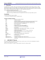
1. Overview
The USB PMSC FIT module, when used in combination with the USB-BASIC-F/W FIT module, operates as a USB
peripheral mass storage class driver (PMSC). The USB peripheral mass storage class driver (PMSC) comprises a USB
mass storage class bulk-only transport (BOT) protocol. When combined with a USB peripheral control driver and media
driver, it enables communication with a USB host as a BOT-compatible storage device.
This module supports the following functions.
・ Storage command control using the BOT protocol
・ Response to mass storage device class requests from a USB host
・ Response to storage commands which are encapsulated in the bulk-only transport (BOT) protocol
Limitations
The following limitations apply to PMSC.
1. Structures are composed of members of different types.
Terms and Abbreviations
1.1
API
APL
BOT
:
:
:
cstd
DDI
H/W
MGR
PCD
PCDC
PCI
PMSCD
PMSCF
PMSDD
PP
pstd
RSK
Scheduler
Scheduler Macro
Task
USB
USB-BASIC-FW
USB-BASIC-FW FIT
:
:
:
:
:
:
:
:
:
:
:
:
:
:
:
:
:
:
:
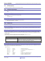
Application Program Interface
Application program
USB mass storage class bulk only transport. See “Universal Serial Bus Mass
Storage Class Bulk-Only Transport” at USB Implementers Forum..
Prefix of Function and File for Host & Peripheral USB-BASIC-FW
Device driver interface, or PMSDD API.
Renesas USB device
Peripheral device state manager of HCD
Peripheral control driver of USB-BASIC-FW
Communications Devices Class for peripheral
PCD interface
Peripheral mass storage USB class driver (PMSCF + PCI + DDI)
Peripheral mass storage class function
Peripheral mass storage device driver (sample ATAPI driver)
Pre-processed definition
Prefix of Function and File for Peripheral USB-Basic-F/W
Renesas Starter Kits
Used to schedule functions, like a simplified OS.
Used to call a scheduler function.
Processing unit
Universal Serial Bus
USB Host and Peripheral Basic Mini Firmware
USB Host and Peripheral Basic Firmware using Firmware Integration
Technology
USB PMSC FIT Module
User needs to integrate this module to the project using r_usb_basic_mini. User can control USB H/W by using this
module API after integrating to the project.
Please refer to the chapter “2.2.8How to add the module” about how to add the module.
R01AN2172EJ0101 Rev.1.01
Jun 1, 2015
Page 3 of 28
Renesas USB MCU
2.
USB Peripheral Mass Storage Class Driver for USB Mini Firmware Using Firmware Integration Technology
Software Configuration
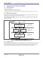
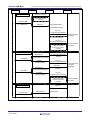
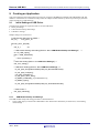
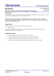
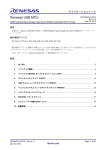
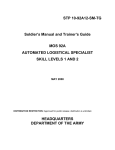
As shown in Figure 2-1, PDCD comprises two layers: PMSCD and PMSDD.
PMSCD comprises three layers: PCD API (PCI), PMSDD API (DDI), and BOT protocol control and data sends and
receives (PMSCF).
PMSCD uses the BOT protocol to communicate with the host via PCD.
PMSDD analyzes and executes storage commands received from PMSCD. PMSDD accesses media data via the media
driver.
Figure 2-1 shows the configuration of the modules.
5 Peripheral Mass Storage Device Driver (PMSDD)
Peripheral
Mass storage
class driver
(PMSCD)
Peripheral
Device class
driver (PDCD)
4 Device Driver Interface (DDI)
3 Peripheral Mass Storage Class Function (PMSCF)
2 PCD Interface (PCI)
6 (Media driver)
1 USB Peripheral Control Driver (PCD)
Media
USB Peripheral H/W
Figure 2-1 Software Configuration Diagram
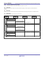
Table 2-1
Module
PMSDD
DDI
Module Function Overview
Description
Mass Storage Device Driver
・ Processes storage commands from the PMSCD
・ Accesses media via the media driver
PMSDD-PMSCD interface function
Peripheral Mass Storage Class Function
PMSCF
PCI
PCD
2.1
・ Controls BOT protocol data and responds to class requests.
・ Analyzes CBWs and transmits/receives data.
・ Generates CSWs together with the PMSDD/PCD.
PMSCD – PCD interface function
USB Peripheral H/W Control driver
Media Driver
This module uses the media driver API of the application note (Block Access Media Driver API: R01AN1443EU). User
needs to use this module with this application note (R01AN1443EU). For details, please refer to this application note
(R01AN1443EU) .
Note: In the USB PMSC FIT module, the media driver is included in the PMSDD.
R01AN2172EJ0101 Rev.1.01
Jun 1, 2015
Page 4 of 28
Renesas USB MCU
2.2
USB Peripheral Mass Storage Class Driver for USB Mini Firmware Using Firmware Integration Technology
API Information
This Driver API follows the Renesas API naming standards.
2.2.1
Hardware Requirements
This driver requires your MCU support the following features:
・ USB
2.2.2
Software Requirements
This driver is dependent upon the following packages:
・ r_bsp
・ r_usb_basic_mini
2.2.3
Supported Toolchains
This driver is tested and working with the following toolchains:
・ Renesas RX Toolchain v.2.02.00
2.2.4
Header Files
All API calls and their supporting interface definitions are located in r_usb_pmsc_mini_if.h.
2.2.5
Integer Types
This project uses ANSI C99 “Exact width integer types” in order to make the code clearer and more portable. These
types are defined in stdint.h.
2.2.6
Compile Setting
In order to use this module, it is necessary to set the USB-BASIC-F/W FIT module as a peripheral. Refer to USBBASIC-F/W FIT module application note (Document No. R01AN2166EJ) for information on USB-BASIC-F/W FIT
module settings.
Please modify r_usb_hcdc_config.h when User sets the module configuration option.
The following table shows the option name and the setting value.
Configuration options in r_usb_atapi_driver_config.h
NOT_USE_MEDIA
ATAPI_MEDIA_DEVICE_DRIVER
USB_ATAPI_BLOCK_UNIT
2.2.7
Disable this macro
Specify the instance name of media_driver_s structure.
Refer to the media driver API application note (Document number:
R01AN1443EU) about media_driver_s structure.
Specify the sector size of using the storage media.
Argument
The structure for the arguments of the API functions is shown below. For details, please refer to USB-BASIC-F/W FIT
module application note (Document No.R01AN2166EJ).
struct usb_utr_t
{
usb_strct_t
usb_strct_t
usb_strct_t
usb_strct_t
usb_cb_t
usb8_t
uint16_t
msginfo;
pipenum ;
status;
flag;
complete;
*tranadr;
*setup;
R01AN2172EJ0101 Rev.1.01
Jun 1, 2015
/* Message information */
/* Sub information(Port No/Pipe No etc) */
/* USB status */
/* Flag */
/* Pointer to the callback function */
/* Pointer to USB transfer buffer */
/* Pointer to Setup packet data */
Page 5 of 28
Renesas USB MCU
uint16_t
usb_leng_t
uint8_t
USB Peripheral Mass Storage Class Driver for USB Mini Firmware Using Firmware Integration Technology
pipectr;
tranlen;
dummy;
/* PIPECTR register */
/* USB data length*/
/* Adjustment of the byte border */
}
2.2.8
How to add the module
This module must be added to an existing e2 studio project. By using the e2 studio plug-in, it is possible to update the
include file path automatically. It is therefore recommended that this plug-in be used to add the project.
For instructions when using e2 studio, refer to RX Family: Adding Firmware Integration Technology Modules to
Projects (document No. R01AN1723EU).
For instructions when using CS+, refer to RX Family: Integration into CS+, Firmware Integration Technology
(document No. R01AN1826EJ).
R01AN2172EJ0101 Rev.1.01
Jun 1, 2015
Page 6 of 28
Renesas USB MCU
3.
USB Peripheral Mass Storage Class Driver for USB Mini Firmware Using Firmware Integration Technology
How to Register Class Driver
The class driver which the user created functions as a class driver by registering with a USB driver.
For details, please refer to "Registration method of a class driver" of USB Basic Host and Peripheral firmware using
Firmware Integration Technology application note (Document No. R01AN2166EJ).
4.
System Resources
The resource which PMSC uses is showed in Table 4-1~Table 4-2.
Table 4-1 Task Information
Function
R_usb_pmsc_task
R_usb_pmsc_atapi_task
Task ID
USB_PMSC_TSK
USB_PFLSH_TSK
Mailbox
USB_PMSC_MBX
USB_PFLSH_MBX
Task ID
USB_PMSC_TSK
USB_PFLSH_TSK
Table 4-2
Priority
USB_PRI_1
USB_PRI_2
Description
PMSCD Task
PMSDD Task
Mailbox Information
Queue
FIFO order
FIFO order
Description
for PMSCD
for PMSDD
5. Task ID and Priority Setting
Define the setting value for User task ID within the following range. The task priority level is the same as the task ID.
The highest priority level becomes 0.
Task ID
: 3 to (USB_IDMAX - 1)
Mailbox ID
: Set the same value as Task ID
[Note]
1. USB_IDMAX is the defined by User in r_usb_basic_mini_config.h file.
2. Task IDs 0 to 2 are already defined. When setting task IDs, use values other than 0 to 2.
R01AN2172EJ0101 Rev.1.01
Jun 1, 2015
Page 7 of 28
Renesas USB MCU
USB Peripheral Mass Storage Class Driver for USB Mini Firmware Using Firmware Integration Technology
6.
Peripheral Device Class Driver (PDCD)
6.1
Basic Functions
The functions of PDCD are to:
1. Storage command control using the BOT protocol.
2. Respond to mass storage class requests from USB host.
3. Respond to USB host storage commands which are encapsulated in the BOT protocol (Bulk Only Transport), see
below)
6.2
BOT Protocol Overview
BOT (USB MSC Bulk-Only Transport) is a transfer protocol that, encapsulates command, data, and status (results of
commands) using only two endpoints (one bulk in and one bulk out).
The ATAPI storage commands and the response status are embedded in a “Command Block Wrapper” (CBW) and a
“Command Status Wrapper” (CSW).
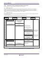
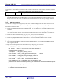
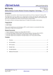
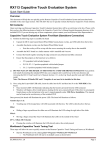
Figure 6-1 shows an overview of how the BOT protocol progresses with command and status data flowing between
USB host and peripheral.
Ready
Command Block Wrapper
Command Transfer
(Host→Device)
Data-Out
(Host→Device)
Data-In
(Device→Host)
Command Status Wrapper
Status transfer
(Device→Host)
CBW transfer stage
(Command packet)
Data transfer stage
(Data packet)
CSW transfer stage
(Status packet)
Figure 6-1 BOT protocol Overview.
Command and status flow between USB host and peripheral.
6.2.1
CBW processing
When PMSCD receives a command block wrapper (CBW) from the host, it first verifies the validity of the CBW. If the
CBW is valid, PMSCD notifies PMSDD of the storage command contained in the CBW and requests analysis of the
command. PMSCD finally performs processing based on the analysis by PMSDD (command validity, data transfer
direction and size) and the information contained in the wrapper (data communication direction and size).
R01AN2172EJ0101 Rev.1.01
Jun 1, 2015
Page 8 of 28
Renesas USB MCU
USB Peripheral Mass Storage Class Driver for USB Mini Firmware Using Firmware Integration Technology
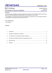
6.2.2
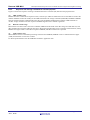
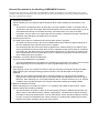
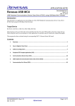
Sequence for storage command with no data transmit/receive
Figure 6-2 shows the sequence of storage commands without data transfer.
(a).
CBW transfer stage
PMSCD issues a CBW receive request to PCD and registers a callback function. When PCD receives the CBW, it
executes a callback function which starts the CBW transfer stage. PMSCD verifies the validity of the CBW and
transfers the storage command (CBWCB) to PMSDD. PMSCD requests PMSDD to execute storage commands.
PMSDD executes the storage command and returns the result to PMSCD.
(b).
CSW transfer stage
Based on the execution result at the time of callback, PMSCD creates a command status wrapper (CSW) and transmits
it to the host via PCD.
For details on PCD operation refer to the USB basic firmware Application note.
Host
PCD
CBW transfer stage
Transmit CBW
Ex.)TEST UNIT READY
PMSCD
PMSDD
CBW receive request
(callback function registration
called when CBW is
received)
(CBW reception preparation)
Call-back
(CBW transfer)
Verify CBW validity
Verify CBW meaning
usb_pmsc_
SmpAtapiAnalyzeCBWCB()
Analyze storage
command
13-case identification
usb_pmsc_
SmpAtapiCommandExecute()
Callback function registration
called when storage
command execution is
completed
CSW transfer stage
Execute storage
command
Call-back
(execution result transfer)
CSW transfer
Create CSW
Transmit CSW
Figure 6-2 Sequence of Storage Command for No Transmit/Receive Data
R01AN2172EJ0101 Rev.1.01
Jun 1, 2015
Page 9 of 28
Renesas USB MCU
USB Peripheral Mass Storage Class Driver for USB Mini Firmware Using Firmware Integration Technology
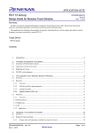
6.2.3
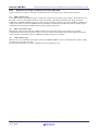
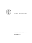
Sequence with storage command for transmit (IN) data
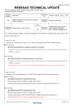
Figure 6-3 shows the sequence of storage command when there is transmit (IN) data from the peripheral side.
(a).
CBW transfer stage
PMSCD executes a CBW receive request to PCD, and sets up a callback. When PCD receives the CBW it executes the
callback. PMSCD verifies the validity of the CBW and transfers the storage command (CBWCB) to PMSDD. PMSDD
analyzes the data transmit command and returns the result to PMSCD. PMSCD then reads the CBW and sends an
ATAPI storage command execution request to PMSDD together with a callback registration.
(b).
Data IN transfer stage
Based on the execution result at the time of callback, PMSCD notifies PCD of the data storage area and data size, and
data communication with the USB host takes place. When the peripheral PCD issues a transmit end notification (status),
PMSCD once again sends a continuation request to PMSDD, and data transmission is repeated.
(c).
CSW transfer stage
When PMSCD receives a command processing end result from PMSDD, PMSCD creates a command status wrapper
(CSW) and transmits it to the host via PCD.
For PCD operation details refer the USB Basic Firmware Application note.
R01AN2172EJ0101 Rev.1.01
Jun 1, 2015
Page 10 of 28
Renesas USB MCU
Host
USB Peripheral Mass Storage Class Driver for USB Mini Firmware Using Firmware Integration Technology
PCD
CBW transfer stage
PMSCD
PMSDD
CBW receive request
(callback function registration
called when CBW is
received)
Transmit CBW
Ex.) READ(10)
Call-back
(CBW transfer)
Verify CBW validity
Verify CBW meaning
usb_pmsc_
SmpAtapiAnalyzeCBWCB()
Analyze storage
command
13-case identification
usb_pmsc_
SmpAtapiCommandExecute()
Callback function registration
called when storage
command execution is
completed
Call-back
Data (IN) transfer stage
Data transfer
IN data
Execute storage
command
(transmit data information)
Call-back
(transmit status)
(transmit data
information transfer)
usb_pmsc_
SmpAtapiCommandExecute()
Execute storage
command
(final data)
Call-back
Data transfer
IN data
(transmit data information)
Call-back
(transmit status)
(transmit data
information transfer)
usb_pmsc_
SmpAtapiCommandExecute()
Callback function registration
called when storage
command execution is
completed
CSW transfer stage
Execute storage
command
Call-back
(execution result transfer)
CSW transfer
Create CSW
Transmit CSW
Figure 6-3 Sequence of Storage Command for Transmit (IN) Data
R01AN2172EJ0101 Rev.1.01
Jun 1, 2015
Page 11 of 28
Renesas USB MCU
USB Peripheral Mass Storage Class Driver for USB Mini Firmware Using Firmware Integration Technology
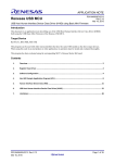
6.2.4
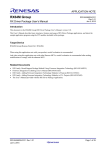
Sequence for storage command with receive (OUT) data
Figure 6-4 shows the sequence of storage command when there is transmit (OUT) data from the peripheral.
(a).
CBW transfer stage
In the CBW transfer stage, PMSCD issues a CBW receive request to PCD and sets up a callback.. When PCD receives
the CBW it executes the callback. PMSCD verifies the validity of the CBW and transfers the storage command
(CBWCB) to PMSDD. PMSDD analyzes the data transmit command, and returns the result to PMSCD. PMSCD then
compares the analysis result from PMSDD with the information contained in the CBW and sends an ATAPI storage
command execution request to PMSDD together with a callback registration.
(b).
Data OUT transfer stage
Based on the callback execution result, PMSCD notifies PCD of the data storage area and data size, and data
communication with the host takes place. When it receives transmit end notification from PCD, PMSCD once again
sends a common continuation request to PMSDD, and data transmission is repeated.
(c).
CSW transfer stage
When it receives a command processing end result from PMSDD, PMSCD creates a command status wrapper (CSW)
and transmits it to the host via PCD.
For PCD operation details refer to the USB Basic Firmware Application note.
R01AN2172EJ0101 Rev.1.01
Jun 1, 2015
Page 12 of 28
Renesas USB MCU
Host
USB Peripheral Mass Storage Class Driver for USB Mini Firmware Using Firmware Integration Technology
PCD
CBW transfer stage
PMSCD
PMSDD
CBW receive request
(callback function registration
called when CBW is
received)
Transmit CBW
Call-back
Ex.) WRITE(10)
(CBW transfer)
Verify CBW validity
Verify CBW meaning
usb_pmsc_
SmpAtapiAnalyzeCBWCB()
Analyze storage
command
13-case identification
usb_pmsc_
SmpAtapiCommandExecute()
Callback function registration
called when storage
command execution is
completed
Data (OUT) transfer stage
Execute storage
command
Call-back
Data transfer
(receive data information)
(receive data information
transfer)
OUT data
Call-back
(receive status)
usb_pmsc_
SmpAtapiCommandExecute()
Call-back
Data transfer
(receive data information)
(receive data information
transfer)
Execute storage
command
(final data)
OUT data
Call-back
(receive status)
usb_pmsc_
SmpAtapiCommandExecute()
Callback function registration
called when storage
command execution is
completed
CSW transfer stage
Execute storage
command
Call-back
(execution result transfer)
CSW transfer
Create CSW
Transmit CSW
Figure 6-4
R01AN2172EJ0101 Rev.1.01
Jun 1, 2015
Sequence of Storage Command for Receive (OUT) Data
Page 13 of 28
Renesas USB MCU
USB Peripheral Mass Storage Class Driver for USB Mini Firmware Using Firmware Integration Technology
6.2.5
Access sequence for class request
Figure 6-5 shows the sequence when a mass storage class request is received.
(a).
Setup Stage
When PCD receives a class request in the control transfer setup stage, it sends a request received notification to
PMSCD.
(b).
Data Stage
PMSCD executes the control transfer data stage and notifies PCD of data stage end by means of a callback function.
(c).
Status Stage
PCD executes the status stage and ends the control transfer.
Host
PCD
PMSCD
PMSDD
Setup stage
Ex.) GetMaxLUN
Request notification
Create MaxLUN
Data stage
Transmit MaxLUN
R_usb_pstd_ControlRead()
Call-back
Status stage
Status
Figure 6-5
R01AN2172EJ0101 Rev.1.01
Jun 1, 2015
Sequence for Class Request
Page 14 of 28
Renesas USB MCU
USB Peripheral Mass Storage Class Driver for USB Mini Firmware Using Firmware Integration Technology
7. USB Peripheral Mass Storage Class Driver (PMSCD)
7.1
Basic Functions
The basic interface functions of PMSCD are to register, open, and close the Peripheral Mass Storage Class Driver.
The rest of the functionality inside PMSCD was already described in the sequence charts in chapter "6 eripheral Device
Class Driver (PDCD)".
7.2
List of API Functions
Table 4.10 List of API Functions
Function Name
R_usb_pmsc_Open
R_usb_pmsc_Close
R_usb_pmsc_task
R_usb_pmsc_driver_start
R01AN2172EJ0101 Rev.1.01
Jun 1, 2015
Description
Open PMSC driver
Close PMSC driver
PMSC task
PMSC driver start
Page 15 of 28
Renesas USB MCU
7.2.1
USB Peripheral Mass Storage Class Driver for USB Mini Firmware Using Firmware Integration Technology
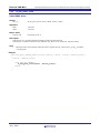
R_usb_pmsc_Open
Open PMSC driver
Format
usb_er_t
R_usb_pmsc_Open(uint16_t data1, uint16_t data2)
Argument
data1
data2
Not used
Not used
Return Value
USB_E_OK
Processing result : 0
Description
This function is to be called when the USB device has been connected, has enumerated and been configured by the
USB host .
The function sets the CBW reception setting.
Note
1. Call this function in the callback function which is registered in the structure(usb_pcdreg_t)
member (statediagram).
Example
void usb_pmsc_change_device_state( uint16_t data1, uint16_t device_state )
{
switch ( device_state )
{
:
case USB_STS_CONFIGURED:
R_usb_pmsc_Open(data1, device_state);
break;
:
}
R01AN2172EJ0101 Rev.1.01
Jun 1, 2015
Page 16 of 28
Renesas USB MCU
7.2.2
USB Peripheral Mass Storage Class Driver for USB Mini Firmware Using Firmware Integration Technology
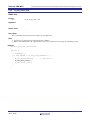
R_usb_pmsc_Close
Close PMSC driver
Format
usb_er_t
R_usb_pmsc_Close( uint16_t data1, uint16_t data2)
Argument
data1
data2
Not used
Not used
Return Value
USB_E_OK
Processing result : 0
Description
This function is to be called when the USB device has been disconnected.
This function is called at transition to the detached state. There are no operations. Add if necessary.
Note
1. Call this function in the callback function which is registered in the structure(usb_pcdreg_t) member
(statediagram).
Example
void usb_pmsc_change_device_state( uint16_t data1, uint16_t device_state )
{
switch ( device_state )
{
case USB_STS_DETACH:
R_usb_pmsc_Close(data1, device_state);
break;
}
}
R01AN2172EJ0101 Rev.1.01
Jun 1, 2015
Page 17 of 28
Renesas USB MCU
7.2.3
USB Peripheral Mass Storage Class Driver for USB Mini Firmware Using Firmware Integration Technology
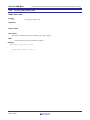
R_usb_pmsc_task
PMSC task
Format
void
R_usb_pmsc_task( void)
Argument
-
-
Return Value
-
-
Description
This is the PMSC task which processes requests by the application.
Note
1. The function is registered to be scheduled by the scheduler.
2. Refer to the USB-BASIC-F/W Application Notes for more information concerning the scheduling process.
Example
void usb_apl_task_switch(void)
{
while( 1 )
{
/* Scheduler */
if( USB_FLGSET == R_usb_cstd_Scheduler() )
{
R_usb_pstd_PcdTask();
/* PCD Task */
R_usb_pmsc_task();
R_usb_atapi_task();
}
}
}
R01AN2172EJ0101 Rev.1.01
Jun 1, 2015
Page 18 of 28
Renesas USB MCU
7.2.4
USB Peripheral Mass Storage Class Driver for USB Mini Firmware Using Firmware Integration Technology
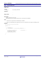
R_usb_pmsc_driver_start
PMSC driver start
Format
void
R_usb_pmsc_task( void)
Argument
-
-
Return Value
-
-
Description
This function initializes the global variable (g_usb_pipe_toggle).
Note
1.
Call this API from the user application program.
Example
void usb_task_start (void)
{
:
R_usb_pmsc_driver_start();
:
}
R01AN2172EJ0101 Rev.1.01
Jun 1, 2015
Page 19 of 28
Renesas USB MCU
USB Peripheral Mass Storage Class Driver for USB Mini Firmware Using Firmware Integration Technology
8.
Peripheral Mass Storage Device Driver (PMSDD)
8.1
Basic Function
The main functions of the PMSDD are as follows.
1. Analyzing storage commands received from the PMSCD
2. Running storage commands received from the PMSCD
3. After running each storage command, transferring to the PMSCD the communication data information and
execution result
8.2
Function
The main function of PMSDD is to analyze and call for execution of storage commands received from the host via
PMSCD. It supports SFF-8070i(ATAPI). This command set is therefore used by the host to control the storage media.
These are the storage commands:
USB_ATAPI_READ10
USB_ATAPI_INQUIRY
USB_ATAPI_REQUEST_SENSE
USB_ATAPI_MODE_SENSE10
USB_ATAPI_READ_FORMAT_CAPACITY
USB_ATAPI_READ_CAPACITY
USB_ATAPI_WRITE10
USB_ATAPI_WRITE_AND_VERIFY
USB_ATAPI_MODE_SELECT10
USB_ATAPI_FORMAT_UNIT
USB_ATAPI_TEST_UNIT_READY
USB_ATAPI_START_STOP_UNIT
USB_ATAPI_SEEK
USB_ATAPI_VERIFY10
USB_ATAPI_PREVENT_ALLOW
PMSDD notifies PMSCD of communication data and execution results related to storage command execution.
PMSDD divides the data transfer intp0 pieces when the transfer data length exceeds the user-specified block count.
A master boot record (FAT12) sample table is provided.
R01AN2172EJ0101 Rev.1.01
Jun 1, 2015
Page 20 of 28
Renesas USB MCU
8.3
USB Peripheral Mass Storage Class Driver for USB Mini Firmware Using Firmware Integration Technology
PMSDD Storage Command Structure
The “storage command structure” is USB_PMSC_CDB_t. The format of a storage command (SFF-8070i) differs
depending on the command category, so a union is used. Four patterns sort out from ten kinds of command type details
as shown in Table 8-1.
Table 8-1
Union Member
s_usb_ptn0
s_usb_ptn12
s_usb_ptn378
s_usb_ptn4569
Type
uint8_t
uint8_t
s_LUN
uint8_t
uint8_t
uint8_t
s_LUN
uint8_t
uint8_t
uint8_t
uint8_t
uint8_t
uint8_t
s_LUN
uint8_t
uint8_t
uint8_t
uint8_t
uint8_t
uint8_t
uint8_t
s_LUN
uint8_t
uint8_t
uint8_t
uint8_t
uint8_t
uint8_t
uint8_t
uint8_t
R01AN2172EJ0101 Rev.1.01
Jun 1, 2015
USB_PMSC_CDB_t Structure
Structure Member
uc_OpCode
b_LUN
b_reserved
uc_data
uc_OpCode
b_LUN
b_reserved4
b_immed
uc_rsv2[2]
uc_Allocation
uc_rsv1[1]
uc_rsv6[6]
uc_OpCode
b_LUN
b_FmtData
b_CmpList
b_Defect
ul_LBA0
ul_LBA1
ul_LBA2
ul_LBA3
uc_rsv6[6]
uc_OpCode
b_LUN
b_1
b_reserved2
b_ByteChk
b_SP
ul_LogicalBlock0
ul_LogicalBlock1
ul_LogicalBlock2
ul_LogicalBlock3
uc_rsv1[1]
us_Length_Hi
us_Length_Lo
uc_rsv3[3]
Bit Count
Command Category
Command determination (common)
3
5
3
4
1
INQUIRY /
REQUEST_SENSE
Not used
3
1
1
3
3
1
2
1
1
READ10 /
WRITE10 /
WRITE_AND_VERIFY /
MODE_SENSE /
READ_FORMAT CAPACITY /
MODE SELECT10
Page 21 of 28
Renesas USB MCU
USB Peripheral Mass Storage Class Driver for USB Mini Firmware Using Firmware Integration Technology
Table 8-2 shows storage commands analysis result .
Table 8-2 The USB_PMSC_CBM_t Structure
- Contains “analysis” result of usb_pmsc_SmpAtapi AnalyzeCbwCb.
Member
uint32_t
ar_rst
PMSDD storage command
analysis RESULT
Data direction.
uint32_t
ul_size
Data size
8.4
Remarks
Direction of data transported in last ATAPI
command.
Size of data in last ATAPI command.
List of PMSDD API
Table 8-3 lists the functions of PMSDD.
Table 8-3
Function Name
R_usb_pmsc_atapi_task
R01AN2172EJ0101 Rev.1.01
Jun 1, 2015
List of PMSDD API
Description
Main task of PMSDD
Page 22 of 28
Renesas USB MCU
8.4.1
USB Peripheral Mass Storage Class Driver for USB Mini Firmware Using Firmware Integration Technology
R_usb_atapi_task
PMSC task
Format
usb_er_t
R_usb_atapi_task(void)
Argument
-
-
Return Value
-
-
Description
ATAPI command processing task.
This API processes to the ATAPI command which is requested from USB HOST.
Note
1. The function is registered to be scheduled by the scheduler.
2. Refer to the USB-BASIC-F/W Application Notes for more information concerning the scheduling process.
Example
void usb_apl_task_switch(void)
{
while( 1 )
{
/* Scheduler */
if( USB_FLGSET == R_usb_cstd_Scheduler() )
{
R_usb_pstd_PcdTask();
/* PCD Task */
R_usb_pmsc_task();
R_usb_atapi_task();
}
}
}
R01AN2172EJ0101 Rev.1.01
Jun 1, 2015
Page 23 of 28
Renesas USB MCU
8.5
USB Peripheral Mass Storage Class Driver for USB Mini Firmware Using Firmware Integration Technology
PMSDD Task Description
PMSDD receives storage commands from PMSCD and executes the storage command. PMSDD also receives host data
transfer results from PMSCD. Table 8-4 lists PMSDD command processing. When the transfer data size exceeds
USB_ATAPI_TRANSFER_UNIT, the data is divided into smaller units and transferred.
For commands that do not involve memory access, the transmitted data is created from the response data tables
g_pmsc_atapi_data_size []
g_pmsc_atapi_rd_dat_idx []
g_pmsc_atapi_req_idx []
g_pmsc_atapi_rd_dat_tbl []. (*1)
(*1)The response data table follows storage command set SFF-8070i, and the index into the table is determined by the
command. Refer to uc_OpCode in Table 8-1USB_PMSC_CDB_t Structure provided in the subclass.
Table 8-4
Corresponding Function for Each Storage Command
Storage command
READ10
INQUIRY
Corresponding Function
pmsc_atapi_get_read_data ()
pmsc_atapi_get_read_data ()
REQUEST_SENSE
pmsc_atapi_get_read_data ()
MODE_SENSE10
pmsc_atapi_get_read_data ()
READ_FORMAT_CAPACITY
pmsc_atapi_get_read_data ()
READ_CAPACITY
pmsc_atapi_get_read_data ()
WRITE10
WRITE_AND_VERIFY
MODE_SELECT10
FORMAT_UNIT
TEST_UNIT_READY
pmsc_atapi_get_write_memory ()
pmsc_atapi_get_write_memory ()
pmsc_atapi_get_write_memory ()
pmsc_atapi_get_write_memory ()
usb_pmsc_SmpAtapiTask()
START_STOP_UNIT
usb_pmsc_SmpAtapiTask()
SEEK
usb_pmsc_SmpAtapiTask()
VERIFY10
usb_pmsc_SmpAtapiTask()
PREVENT_ALLOW
usb_pmsc_SmpAtapiTask()
others
usb_pmsc_SmpAtapiTask()
R01AN2172EJ0101 Rev.1.01
Jun 1, 2015
Description
Gets start address and size.
Selects response data from array
g_pmsc_atapi_rd_dat_tbl.
Selects response data from array
g_pmsc_atapi_rd_dat_tbl.
Selects response data from array
g_pmsc_atapi_rd_dat_tbl.
Selects response data from array
g_pmsc_atapi_rd_dat_tbl.
Selects response data from array
g_pmsc_atapi_rd_dat_tbll.
Gets start address and size.
Gets start address and size.
Gets start address and size.
Gets start address and size.
Status =
USB_PMSC_CMD_COMPLETE
Status =
USB_PMSC_CMD_COMPLETE
Status =
USB_PMSC_CMD_COMPLETE
Status =
USB_PMSC_CMD_COMPLETE
Status =
USB_PMSC_CMD_FAILED
Status =
USB_PMSC_CMD_ERROR
Page 24 of 28
Renesas USB MCU
USB Peripheral Mass Storage Class Driver for USB Mini Firmware Using Firmware Integration Technology
9. Creating an Application
This section describes the initial settings necessary for using the USB PMSC FIT module and USB-BASIC-F/W FIT
module in combination as a USB driver and presents an example of data transfer by means of processing by the main
routine and the use of API functions.
9.1
Initial Settings of USB Driver
The following settings are required in order to use the USB driver.
MCU pin settings
USB controller startup and settings
USB driver settings
Sample settings are shown below.
/* USB Transfer Structure for PMSC */
usb_utr_t
usb_gpmsc_utr
void usb_pmsc_apl(void)
{
usb_er_t
err;
/* USB module starting and setting (Refer to “9.1.1 USB Module Startup and Settings”) */
err = R_USB_Open();
if(err != USB_SUCCESS)
{
/* Error processing */
}
/* MCU Pin Setting (Refer to “9.1.2 MCU Pin Settings”) */
usb_mcu_setting();
/* USB Driver Setting (Refer to “9.1.3 USB Driver Settings”) */
R_usb_pstd_ChangeDeviceState(USB_DO_INITHWFUNCTION);
R_usb_pstd_PcdOpen();
usb_papl_registration();
R_usb_pmsc_driver_start();
R_MEDIA_Initialize(&g_EepromMediaDriver);
R_MEDIA_Open();
R_usb_pstd_ChangeDeviceState(USB_DO_SETHWFUNCTION);
/* Main routine */
usb_papl_mainloop();
}
9.1.1
USB Module Startup and Settings
The USB module startup and setting procedure is described below.
1. Call R_USB_Open() to launch the USB module. This API function should only be called once, when making
initial settings.
R01AN2172EJ0101 Rev.1.01
Jun 1, 2015
Page 25 of 28
Renesas USB MCU
USB Peripheral Mass Storage Class Driver for USB Mini Firmware Using Firmware Integration Technology
9.1.2
MCU Pin Settings
It is necessary to make USB I/O pin settings in order to use the USB controller. Sample USB I/O pin settings are shown
below.
Table9-1 USB I/O Pin Settings for Peripheral Operation
Pin Name
I/O
Description
USB_VBUS
Input
USB VBUS pin
[Note]
The USB PMSC FIT module and USB-BASIC-F/W FIT module do not make microcontroller pin settings. If pin
settings are necessary, refer to the user’s manual of the specific microcontroller and make pin settings to match the
specifications of the evaluation board to be used.
9.1.3
USB Driver Settings
The USB driver settings consist of registering a task with the scheduler and registering class driver information for the
USB-BASIC-F/W FIT module. The procedure for registering the class driver information and registering the task with
the scheduler is described below.
1. Call the USB-BASIC-FW FIT module’s API function (R_usb_pstd_ChangeDeviceState()) to reset the USB-IP.*1
2. Call the USB-BASIC-F/W FIT module’s API functions (R_usb_pstd_PcdOpen()) to register the PCD task with the
scheduler.
3. After setting the information for the members of the class driver registration structure (usb_pcdreg_t) with the
usb_papl_registration() function, call R_usb_pstd_DriverRegistration() to register the class driver information for
the USB-BASIC-FW FIT module.
4. Call the class driver’s API function (R_usb_pmsc_driver_start()) to perform initialization.
5. Call the media driver’s API functions (R_MEDIA_Initialize() and R_MEDIA_Open()) to initialize the media driver.
6. Call the USB-BASIC-FW FIT module’s API function (R_usb_pstd_ChangeDeviceState) to set the USB-IP
functionality to peripheral.*1
[Note]
1. Run USB_DO_INITHWFUNCTION before starting USB-BASIC-F/W, and run USB_DO_SETHWFUNCTION
after registering the UPL.
A sample of information specified in the structure declared by usb_pcdreg_t is shown below.
void usb_papl_registration()
{
usb_pcdreg_t
driver; /* Structure for the class driver registration */
/* Pipe information table setting */
driver.pipetbl
= usb_gpmsc_EpPtr[0]; // Note 1
/* Set the Device Descriptor table */
driver.devicetbl = (uint8_t*)&usb_gpmsc_DeviceDescriptor;
// Note 2
/* Set the Configuration Descriptor table */
driver.configtbl = &usb_gpmsc_ConfigrationF1[0]; // Note 2, 3
/* Set the String Descriptor */
driver.stringtbl
= (uint8_t**)&usb_gpmsc_StrPtr[0]; // Note 2, 4
/* Set the function which is called when a USB state transition occurs */
driver.statediagram = (usb_cbinfo_t)&usb_psmpl_change_device_state;
/* Set the function which is called when processing the control transfer other than the standard request
*/
driver.ctrltrans = &usb_pmsc_UsrCtrlTransFunction;
/* Register the class driver information to PCD */
R_usb_pstd_DriverRegistration(&driver);
}
R01AN2172EJ0101 Rev.1.01
Jun 1, 2015
Page 26 of 28
Renesas USB MCU
1.
USB Peripheral Mass Storage Class Driver for USB Mini Firmware Using Firmware Integration Technology
[Note]
The pipe information table need to be defined in the application program. Refer to USB Basic Firmware
application note (Document No.R01AN2166EJ) about the pipe information table.
= Example of Pipe Information Table =
uint16_t usb_gpmsc_EpTbl[] =
{
USB_PIPE4,
USB_BULK | USB_BFREOFF | USB_DBLBON | USB_SHTNAKON |
USB_DIR_P_IN | USB_EP1,
USB_MAX_PACKET(64),
USB_NULL,
USB_PIPE5,
USB_BULK | USB_BFREOFF | USB_DBLBON | USB_SHTNAKON |
USB_DIR_P_OUT | USB_EP2,
USB_MAX_PACKET(64),
USB_NULL,
/* Pipe end */
USB_PDTBLEND
2.
};
Create each descriptor based on USB specification.
3.
Set the start address of array which is set the configuration descriptor start address in this member.
4.
Set the start address of array (Refer to the following) which is set the string descriptor start address in this member.
uint8_t *usb_gpmsc_StrPtr[] =
{
usb_gpmsc_StringDescriptor0,
usb_gpmsc_StringDescriptor1,
usb_gpmsc_StringDescriptor2,
}
9.2
Processing by Main Routine
After the USB driver initial settings, call the scheduler (R_usb_cstd_Scheduler()) from the main routine of the
application. Calling R_usb_cstd_Scheduler() from the main routine causes a check for events. If there is an event, a flag
is set to inform the scheduler that an event has occurred. Also, it is necessary to run processing at regular intervals to get
events and perform the appropriate processing. (Note1)
void usb_papl_mainloop(void)
{
while(1) // Main routine
{
if(USB_FLGSET == R_usb_cstd_Scheduler()) // Judgment whether the event is or not(Note1)
{
R_usb_pstd_PcdTask();
// HCD task
R_usb_pmsc_task();
// MSC task
R_usb_atapi_task();
// ATAPI task
}
pmsc_application();
// User application program
}
}
(Note2)
[Note]
1.
If, after getting an event with R_usb_cstd_Scheduler() and before running the corresponding processing,
R_usb_cstd_Scheduler() is called again and gets another event, the first event is discarded. After getting an event,
always call the corresponding task to perform the appropriate processing.
2.
Be sure to describe these processes in the main loop for the application program.
9.3
Vendor ID
Please be sure to use your vendor ID.
R01AN2172EJ0101 Rev.1.01
Jun 1, 2015
Page 27 of 28
Renesas USB MCU
USB Peripheral Mass Storage Class Driver for USB Mini Firmware Using Firmware Integration Technology
Website and Support
Renesas Electronics Website
http://www.renesas.com/
Inquiries
http://www.renesas.com/inquiry
All trademarks and registered trademarks are the property of their respective owners.
R01AN2172EJ0101 Rev.1.01
Jun 1, 2015
Page 28 of 28
Revision Record
Rev.
1.00
1.01
Date
Dec 1, 2014
Jun 1, 2015
Description
Page
Summary
—
First edition issued
—
RX231 is added in the target device.
A-1
General Precautions in the Handling of MPU/MCU Products
The following usage notes are applicable to all MPU/MCU products from Renesas. For detailed usage notes on the
products covered by this document, refer to the relevant sections of the document as well as any technical updates that
have been issued for the products.
1. Handling of Unused Pins
Handle unused pins in accordance with the directions given under Handling of Unused Pins in the
manual.
The input pins of CMOS products are generally in the high-impedance state. In operation with an
unused pin in the open-circuit state, extra electromagnetic noise is induced in the vicinity of LSI, an
associated shoot-through current flows internally, and malfunctions occur due to the false
recognition of the pin state as an input signal become possible. Unused pins should be handled as
described under Handling of Unused Pins in the manual.
2. Processing at Power-on
The state of the product is undefined at the moment when power is supplied.
The states of internal circuits in the LSI are indeterminate and the states of register settings and
pins are undefined at the moment when power is supplied.
In a finished product where the reset signal is applied to the external reset pin, the states of pins
are not guaranteed from the moment when power is supplied until the reset process is completed.
In a similar way, the states of pins in a product that is reset by an on-chip power-on reset function
are not guaranteed from the moment when power is supplied until the power reaches the level at
which resetting has been specified.
3. Prohibition of Access to Reserved Addresses
Access to reserved addresses is prohibited.
The reserved addresses are provided for the possible future expansion of functions. Do not access
these addresses; the correct operation of LSI is not guaranteed if they are accessed.
4. Clock Signals
After applying a reset, only release the reset line after the operating clock signal has become stable.
When switching the clock signal during program execution, wait until the target clock signal has
stabilized.
When the clock signal is generated with an external resonator (or from an external oscillator)
during a reset, ensure that the reset line is only released after full stabilization of the clock signal.
Moreover, when switching to a clock signal produced with an external resonator (or by an external
oscillator) while program execution is in progress, wait until the target clock signal is stable.
5. Differences between Products
Before changing from one product to another, i.e. to a product with a different part number, confirm
that the change will not lead to problems.
The characteristics of an MPU or MCU in the same group but having a different part number may
differ in terms of the internal memory capacity, layout pattern, and other factors, which can affect
the ranges of electrical characteristics, such as characteristic values, operating margins, immunity
to noise, and amount of radiated noise. When changing to a product with a different part number,
implement a system-evaluation test for the given product.
Notice
1.
Descriptions of circuits, software and other related information in this document are provided only to illustrate the operation of semiconductor products and application examples. You are fully responsible for
the incorporation of these circuits, software, and information in the design of your equipment. Renesas Electronics assumes no responsibility for any losses incurred by you or third parties arising from the
use of these circuits, software, or information.
2.
Renesas Electronics has used reasonable care in preparing the information included in this document, but Renesas Electronics does not warrant that such information is error free. Renesas Electronics
3.
Renesas Electronics does not assume any liability for infringement of patents, copyrights, or other intellectual property rights of third parties by or arising from the use of Renesas Electronics products or
assumes no liability whatsoever for any damages incurred by you resulting from errors in or omissions from the information included herein.
technical information described in this document. No license, express, implied or otherwise, is granted hereby under any patents, copyrights or other intellectual property rights of Renesas Electronics or
others.
4.
You should not alter, modify, copy, or otherwise misappropriate any Renesas Electronics product, whether in whole or in part. Renesas Electronics assumes no responsibility for any losses incurred by you or
5.
Renesas Electronics products are classified according to the following two quality grades: "Standard" and "High Quality". The recommended applications for each Renesas Electronics product depends on
third parties arising from such alteration, modification, copy or otherwise misappropriation of Renesas Electronics product.
the product's quality grade, as indicated below.
"Standard": Computers; office equipment; communications equipment; test and measurement equipment; audio and visual equipment; home electronic appliances; machine tools; personal electronic
equipment; and industrial robots etc.
"High Quality": Transportation equipment (automobiles, trains, ships, etc.); traffic control systems; anti-disaster systems; anti-crime systems; and safety equipment etc.
Renesas Electronics products are neither intended nor authorized for use in products or systems that may pose a direct threat to human life or bodily injury (artificial life support devices or systems, surgical
implantations etc.), or may cause serious property damages (nuclear reactor control systems, military equipment etc.). You must check the quality grade of each Renesas Electronics product before using it
in a particular application. You may not use any Renesas Electronics product for any application for which it is not intended. Renesas Electronics shall not be in any way liable for any damages or losses
incurred by you or third parties arising from the use of any Renesas Electronics product for which the product is not intended by Renesas Electronics.
6.
You should use the Renesas Electronics products described in this document within the range specified by Renesas Electronics, especially with respect to the maximum rating, operating supply voltage
range, movement power voltage range, heat radiation characteristics, installation and other product characteristics. Renesas Electronics shall have no liability for malfunctions or damages arising out of the
use of Renesas Electronics products beyond such specified ranges.
7.
Although Renesas Electronics endeavors to improve the quality and reliability of its products, semiconductor products have specific characteristics such as the occurrence of failure at a certain rate and
malfunctions under certain use conditions. Further, Renesas Electronics products are not subject to radiation resistance design. Please be sure to implement safety measures to guard them against the
possibility of physical injury, and injury or damage caused by fire in the event of the failure of a Renesas Electronics product, such as safety design for hardware and software including but not limited to
redundancy, fire control and malfunction prevention, appropriate treatment for aging degradation or any other appropriate measures. Because the evaluation of microcomputer software alone is very difficult,
please evaluate the safety of the final products or systems manufactured by you.
8.
Please contact a Renesas Electronics sales office for details as to environmental matters such as the environmental compatibility of each Renesas Electronics product. Please use Renesas Electronics
products in compliance with all applicable laws and regulations that regulate the inclusion or use of controlled substances, including without limitation, the EU RoHS Directive. Renesas Electronics assumes
no liability for damages or losses occurring as a result of your noncompliance with applicable laws and regulations.
9.
Renesas Electronics products and technology may not be used for or incorporated into any products or systems whose manufacture, use, or sale is prohibited under any applicable domestic or foreign laws or
regulations. You should not use Renesas Electronics products or technology described in this document for any purpose relating to military applications or use by the military, including but not limited to the
development of weapons of mass destruction. When exporting the Renesas Electronics products or technology described in this document, you should comply with the applicable export control laws and
regulations and follow the procedures required by such laws and regulations.
10. It is the responsibility of the buyer or distributor of Renesas Electronics products, who distributes, disposes of, or otherwise places the product with a third party, to notify such third party in advance of the
contents and conditions set forth in this document, Renesas Electronics assumes no responsibility for any losses incurred by you or third parties as a result of unauthorized use of Renesas Electronics
products.
11. This document may not be reproduced or duplicated in any form, in whole or in part, without prior written consent of Renesas Electronics.
12. Please contact a Renesas Electronics sales office if you have any questions regarding the information contained in this document or Renesas Electronics products, or if you have any other inquiries.
(Note 1)
"Renesas Electronics" as used in this document means Renesas Electronics Corporation and also includes its majority-owned subsidiaries.
(Note 2)
"Renesas Electronics product(s)" means any product developed or manufactured by or for Renesas Electronics.
http://www.renesas.com
SALES OFFICES
Refer to "http://www.renesas.com/" for the latest and detailed information.
Renesas Electronics America Inc.
2801 Scott Boulevard Santa Clara, CA 95050-2549, U.S.A.
Tel: +1-408-588-6000, Fax: +1-408-588-6130
Renesas Electronics Canada Limited
9251 Yonge Street, Suite 8309 Richmond Hill, Ontario Canada L4C 9T3
Tel: +1-905-237-2004
Renesas Electronics Europe Limited
Dukes Meadow, Millboard Road, Bourne End, Buckinghamshire, SL8 5FH, U.K
Tel: +44-1628-585-100, Fax: +44-1628-585-900
Renesas Electronics Europe GmbH
Arcadiastrasse 10, 40472 Düsseldorf, Germany
Tel: +49-211-6503-0, Fax: +49-211-6503-1327
Renesas Electronics (China) Co., Ltd.
Room 1709, Quantum Plaza, No.27 ZhiChunLu Haidian District, Beijing 100191, P.R.China
Tel: +86-10-8235-1155, Fax: +86-10-8235-7679
Renesas Electronics (Shanghai) Co., Ltd.
Unit 301, Tower A, Central Towers, 555 Langao Road, Putuo District, Shanghai, P. R. China 200333
Tel: +86-21-2226-0888, Fax: +86-21-2226-0999
Renesas Electronics Hong Kong Limited
Unit 1601-1611, 16/F., Tower 2, Grand Century Place, 193 Prince Edward Road West, Mongkok, Kowloon, Hong Kong
Tel: +852-2265-6688, Fax: +852 2886-9022
Renesas Electronics Taiwan Co., Ltd.
13F, No. 363, Fu Shing North Road, Taipei 10543, Taiwan
Tel: +886-2-8175-9600, Fax: +886 2-8175-9670
Renesas Electronics Singapore Pte. Ltd.
80 Bendemeer Road, Unit #06-02 Hyflux Innovation Centre, Singapore 339949
Tel: +65-6213-0200, Fax: +65-6213-0300
Renesas Electronics Malaysia Sdn.Bhd.
Unit 1207, Block B, Menara Amcorp, Amcorp Trade Centre, No. 18, Jln Persiaran Barat, 46050 Petaling Jaya, Selangor Darul Ehsan, Malaysia
Tel: +60-3-7955-9390, Fax: +60-3-7955-9510
Renesas Electronics India Pvt. Ltd.
No.777C, 100 Feet Road, HALII Stage, Indiranagar, Bangalore, India
Tel: +91-80-67208700, Fax: +91-80-67208777
Renesas Electronics Korea Co., Ltd.
12F., 234 Teheran-ro, Gangnam-Gu, Seoul, 135-080, Korea
Tel: +82-2-558-3737, Fax: +82-2-558-5141
© 2015 Renesas Electronics Corporation. All rights reserved.
Colophon 5.0