1
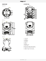
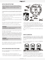
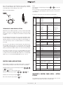
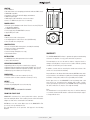
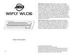
USER MANUAL V.1
ENGLISH VERSION
09 16 2015
Summary
4
4
4
5
6
6
7
7
7
8
8
12
13
14
14
14
15
Introduction
Safety instructions
Conditions of use
Presentation and features
Dimensions
Description
Installation instructions
Installation method using truss hooks
DMX512 connection
Control Panel
MagicBlade R control panel menu - Option details
Master/Slave Mode settings
DMX Chart
Error Messages
Care and maintenance
Technical Specifications
Warranty
USER MANUAL _ 3
Introduction
have not been damaged due to cuts and splices or crushed in any way.
Handle these cables with extreme caution while they are connected to a
power source.
Thank you for selecting the AYRTON MAGICDOT-R luminaire.
Your MAGICDOT-R conforms to Class 1 safety standards. The unit must be
grounded electrically. Make sure that the power source connected to your
MAGICDOT-R is switched off before attempting any work on it.
WARNING !
This product is not suitable for household use.
You now own a professional lighting unit that offers endless possibilities.
Before installing, make sure that no damage was done to your luminaire
during transport. If this is the case, do not use the product and immediately
contact your authorized AYRTON dealer.
For your own safety and that of others, please read this instruction manual
carefully before installing the unit.
Anyone involved in installing, operating or servicing the MAGICDOT-R
must:
•• Be a qualified, authorized professional
•• Strictly follow the instructions in this user manual.
Please take the time to read this manual carefully and thoroughly before
installing and operating the luminaire. You should have a good knowledge
of its operating conditions and all pertinent product information.
After you have become familiar with this manual, we recommend that
you keep a copy for future use. All the information found in this manual
is subject to change without notice. AYRTON reserves the right to modify
and upgrade its range of products, with no obligation to integrate these
changes into products already sold.
Installation and connection to an electrical source must be performed
by an authorized installer. AYRTON declines all responsibility should this
luminaire be installed by an unqualified person.
Never disconnect your MAGICDOT-R by pulling on the power cable!
First unlock the connector lock ring on the power cable until it is fully
disengaged, and then gently pull on the connector to disconnect the cable.
Do not connect or disconnect the power cable of your MAGICDOT-R with
wet hands.
At first use, your MAGICDOT-R may give off an odor. This is a normal
occurrence that should dissipate after a few minutes of operation.
WARNING!
Do not connect or disconnect the power cable at your MAGICDOT-R
if the cable is energized! This could cause arcing and damage your
MAGICDOT-R, requiring repair.
Be careful to power off your MAGICDOT-R by removing the power plug
from the source, before connecting or disconnecting the luminaire.
WARNING!
This unit contains Class 2 LED emitters (EN60625-1): 1994)
SAFETY INSTRUCTIONS
Please read the safety instructions and warnings in this manual carefully
before installing and operating the MAGICDOT-R.
WARNING!
Risk of electric shock.
Use caution when handling. This luminaire requires high voltage,
which can result in electric shock.
The MAGICDOT-R left our factory in perfect working condition. However, if
you notice a defect, immediately contact your authorized AYRTON dealer
before use. The manufacturer cannot be held responsible for damages
caused by a failure to follow the safety, installation or assembly instructions
contained herein, or by any modification made to the luminaire.
Failure to observe the safety, installation or assembly instructions
contained herein, or any modification made to the MAGICDOT-R luminaire
will render the warranty null and void.
Check that the supply voltage does not exceed the maximum authorized
limit. Check that your electrical installation complies with current
standards.
In all cases, make sure that the power cables attached to your MAGICDOT-R
This luminaire uses single high-power (Class 2) LED-type (Light Emitting
Diode) lamps. Never look directly into the lamps if lit or stand directly in
line with the luminaire if close by.
Installation, removal or replacement of the unit must be performed with
power off to prevent any risk of glare and eye injury.
WARNING!
The fixture quickly becomes very hot during operation.
To avoid risk of burn, never handle or adjust the luminaire while it is
energized and after it has been lit for more than 10 consecutive minutes.
Some parts of the luminaire can reach a high temperature, particularly the
body/radiator. Turn off the luminaire and wait for it to cool before handling.
Conditions of use
Your MAGICDOT-R is a moving-head luminaire equipped with single LED
intended for professional use (e.g., architectural, stage, television, theater,
or museum lighting).
The MAGICDOT-R luminaire has an IP20 protection rating. It is intended
USER MANUAL _ 4
strictly for indoor use. It must never be partially or fully submerged, even
temporarily.
Condensation may form on your MAGICDOT-R in the following cases:
•• Immediately after turning on the heating
•• In places with fog or a high level of humidity
•• When the luminaire is suddenly moved from a cold to a warm
environment, or vice versa.
In such cases, you must wait until the luminaire readjusts to the ambient
temperature of the room where it will be installed for operation.
compatible with this information.
Check that the bracket on which you hang or attach your MAGICDOT-R
can sustain the weight of the luminaire (5.3 kg), taking into consideration
all necessary safety factors.
Do not use your MAGICDOT-R before being familiar with these
recommendations and do not allow unqualified personnel to handle the
product.
To transport your MAGICDOT-R, we strongly recommend that you use the
complete original packaging, including the dense protective foam inserts.
Do not shake the MAGICDOT-R while installing or handling.
Do not pull the MAGICDOT-R by one of its cables to move it. Lift the
luminaire by its handles.
Choosing the appropriate place to install the MAGICDOT-R is essential.
The following points should be observed:
•• Do not expose it to a heat source.
•• Do not install it near flammable materials.
•• Be sure that dust or miscellaneous debris cannot clump around the
body of the luminaire as this may interfere with its optimal cooling and
proper operation.
•• The MAGICDOT-R must be installed out of reach of the public and all
persons not authorized to operate the luminaire.
We recommend a minimum distance of 20 cm between the outside
surface of the light and the illuminated object. The color mixture of the
MAGICDOT-R can be improved if the illuminated surface is very close to
the luminaire (up to about 50 cm).
Due to the nature of its cooling principle, you should never prevent air from
circulating around the body of the luminaire. You must provide a minimum
clearance of 20 cm around your MAGICDOT-R to allow for cooling.
The MAGICDOT-R can be installed in a ground pit or any other confined
enclosure only under certain conditions. With this kind of installation, a
system of forced ventilation should be used up to allow air to circulate
freely around the luminaire(s). The air must be constantly renewed
because the luminaire cannot be operated in closed system. Failure to
comply with these requirements may destroy or prematurely wear the
MAGICDOT-R, and AYRTON cannot be held responsible. Please consult
your AYRTON dealer for more information on this type of installation.
If your MAGICDOT-R is not being used for a long period, you should
disconnect the luminaire from the power source.
Never dispose of the MAGICDOT-R in a rubbish bin. Ensure that it is
recycled. Please consult the current legislation in your country on recycling
electronic equipment.
WARNING!
The number of daisy chain, or tandem, connections to the
MAGICDOT-R (power input and output sockets on the luminaires)
is limited for safety reasons. The maximum authorized number of
connections is as follows, with the power line protected by a 10A
circuit breaker:
16 MAGICDOT-R units on the same source at 230 VAC or
6 MAGICDOT-R units on the same source at 110 VAC.
PRESENTATION AND FEATURES
MAGICDOT-R is a non-waterproof moving head wash light (IP20 protection
rating) using the latest generation of high-performance of LED-type lamps.
This luminaire can be controlled remotely by an external DMX512 signal.
The MAGICDOT-R incorporates multi-chip LED using 4 colors: Red, green,
blue and white.
This color-light luminaire operates on the CMY additive color principle and
along with white light can potentially render a palette of 4.2 billion colors.
No load should be placed on the MAGICDOT-R. The fixture must not be
installed in such a way as to allow a person, vehicle or any object to run
over or park on it.
The MAGICDOT-R has a total of 1 LED. The luminaire requires from 15 to
17 DMX channels to be controlled via an external command system that
sends a DMX512 signal (see below for details).
Never lay or drop any hard, heavy, or blunt, objects on the MAGICDOT-R.
This includes items made of glass or porcelain (e.g., bottles, dishware,
or glass beads). The luminaire is made of materials such as plastic and
extruded aluminum, making it resistant but not unbreakable. Objects
made of hard materials such as steel or glass that fall on the unit may
cause breakage of the plastic parts or the body. AYRTON cannot be held
responsible for the luminaire’s broken plastic parts or body, which are not
covered under warranty.
To adjust the settings on the MAGICDOT-R (i.e., DMX address, DMX
operating mode and other options), a Remote Device Management
(RDM)-type DMX controller may be required. The DMX RDM protocol is a
universal, widely used standard.
The temperature of the room where the MAGICDOT-R is installed must
never exceed 45°C (Ta = 45°C).
The MAGICDOT-R luminaire requires a 110-240 VAC supply voltage.
Check that your luminaires have been installed for an application that is
There are a multitude of RDM DMX controllers on the market from different
manufacturers (excluding AYRTON). It is worth noting that an RDM DMX
controller is not required to change the settings on the MAGICDOT-R. A
light console or any standard DMX-type controller is sufficient.
The MAGICDOT-R consists of a metal frame and plastic covers. The power
connectors and DMX512 signal connectors are on the back of the fixture’s
base.
USER MANUAL _ 5
Dimensions
Description
Bottom view
210
9
8
2
113
7
1
5
3
113
4
6
Front view
210
289
303.6
10
11 12 13
Side view
168.5
1. LCD Display
2. Left button
3. Down button
4. Enter button
5. Right button
6. Handle
7. Up button
8. Mode/Esc button
9. LED Collimater
10. Power source input connector (5-pin)
11. Power source output connector (5-pin)
12. DMX512 input connector (5-pin)
13. DMX512 output connector (5-pin)
USER MANUAL _ 6
INSTALLATION INSTRUCTIONS
During installation please observe the instructions according to
GB7000.15 / EN60598-2-17 standards and other national standards
applicable. This luminaire should be installed by a qualified
technician.
The fixture should be used in an environment with a temperature between
-5°C and +45°C. Do not operate the luminaire outside this temperature
range.
The luminaire must be hung so that the weight of this unit multiplied by
10 can be sustained for 1 hour without causing the suspension system or
the supporting structure to be deformed.
The installation must always be secured at a second attach point, e.g., by
a safety cable of the appropriate size.
Do not stand under the luminaire while it is being installed, dismantled
or serviced.
The operator must ensure that a qualified technician has approved the
installation of the luminaire for safety before it is first operated.
Installation should be inspected once a year by a qualified technician.
WARNING!
The installation of this luminaire must be validated by a qualified
technician before it is used for the first time.
The luminaire should be installed in a location where the public cannot,
touch, walk or sit on the luminaire.
Suspending the luminaire and/or installing it high up requires considerable
experience, e.g., calculating load, selecting and adapting quality fastening
materials, and periodically inspecting the entire installation. Without this
skill and knowledge, do not attempt to install this unit by yourself. Improper
installation may cause an accident resulting in personal injury or death.
WARNING!
The luminaire should be connected to an electrical source by a
qualified electrician.
Before installing the luminaire make sure that the selected installation
spot can support at least 10 times the weight of the unit. Connect the
luminaire to the power source by the power cord.
•• Attach the clamp to the omega bracket using an M12 screw.
•• Insert the quick-lock fasteners of the omega bracket into the respective
holes on the base of the unit. Turn the quick fasteners fully clockwise.
•• Insert the safety cable through the holes at the bottom of the base and
the truss or a stable attachment point. Insert the end into the hole and
tighten the safety screw.
Note: The last step is very important to ensure that the luminaire does
not fall.
DMX512 connection
Connect the DMX input (XLR connector) cable of the luminaire to the DMX
output (female XLR connector) of your controller. You can connect multiple
luminaires to this same DMX line in a daisy chain. The DMX cable must
be a shielded twisted pair that is equipped with male and female XLR
connectors.
Refer to the following diagram when connecting the MAGICDOT-R
luminaires in a daisy chain:
INSTALLATION METHOD USING TRUSS HOOKS
Refer to the following diagram when installing the MAGICDOT-R with truss
hoos using omega bracket:
•• Attach the clamp to the omega bracket using an M12 screw.
•• Insert the quick-lock fasteners of the omega bracket into the respective
holes on the base of the unit. Turn the quick fasteners fully clockwise.
DMX512 CONNECTION WITH TERMINATION PLUG
For installations where the DMX cable must extend over long distances,
or if it is located near areas with major electrical disturbance, it is
recommended to use a DMX termination plug. This helps prevent
luminaires from malfunctioning due to interference. The DMX termination
USER MANUAL _ 7
plug, composed simply of a male XLR input connector with a 120-Ohm
resistor, is soldered between pins 2 and 3. This plug must be connected
to the DMX output of the last luminaire in the chain.
Refer to the following diagram:
Notes:
or
keys from the
You can return to the display by pressing the
basic display.
If the screen fails to respond, hold the “Mode Esc” key down for at least
3 seconds to free up the display. key down for at least 3 seconds to free
up the display.
The fixture’s menu functions are described in the following table:
Address Set DMX Addr
DMX address setting
Stand Mode
Basic Mode
Extend Mode
User Mode A
User Mode B
User Mode C
User’s mode to change
channel numbers
Edit User
Max channel
PAN :
Preset User modes
Status
No DMX Mode
Pan Reverse
Tilt Reverse
Pan Degree
Tilt Degree
Feedback
Pan/Tilt Spd
Hibernation
Close/Hold/Auto/Music
ON/OFF
ON/OFF
630/540
270/540
ON/OFF
Speed 1~ 4
OFF, 01min > 99min
Auto run if no DMX
Pan Reverse movement
Tilt Reverse movement
Pan Degree Select
Tilt Degrtee Select
Movement Feedback
Reset Pan/Tilt
Stand by Mode
Service PIN
Service PIN
RDM PID
Password=XXX
xxxxxx
Service Password“=050”
RDM PID Code
Fans Control
Head Control
Auto
Stage
Studio
Head Fans Speed Mode
Select
02~60m 05m
ON/OFF
ON/OFF
ON/OFF
Display shutoff time
Reverse 180 degree
Key Lock
No Signal Flash
Users Mode
A001~AXXX
User Mode
All luminaires have a DMX start address correctly set when using a DMX
signal to control them. The DMX start address is the channel from which
the luminaire “listens” to the digital control information sent by the DMX
controller.
Options
The MAgicdot-r DMX address setting
Shutoff Time
Flip Display
Key Lock
DispFlash
Temp. C/F
Celsius
Fahrenheit
Initial Pos.
PAN =XXX
Trigger
If you do set the same address for all the luminaires, they will all “listen”
from the DMX channel you have set. The instructions sent by the DMX
controller will affect all luminaires at the same time. If you set a different
address per luminaire, the DMX controller can control each independently.
DMX Value Disp.
Set To Slave
Auto Program
ResetDefault
ON/OFF
Restore factory sett.
Time Info.
Current Time
Ttl Life Hrs
Last Run Hrs
Timer PIN
Clr Last Run
XXXX(Hours)
XXXX(Hours)
XXXX(Hours)
Password=XXX
ON/OFF
Temp. Info
Head Temp.
XXX °C/°F
Software Ver
V1.0...
Software version
Home
All
Pan&Tilt
Reset all motors
Reset Pan&Tilt
Test Channel
PAN ……
Test function
Manual Ctrl.
PAN =XXX
:
Fine adjustment of
parameters
Calibration
--Password-PAN
:
Password “050”
Calbrate and adjust the
effects to standard/right
position
Select Prog.
Prog. Part 1 = Program 1 ~ 10 Program 1
Prog. Part 2 = Program 1 ~ 10 Program 2
Prog. Part 3 = Program 1 ~ 10 Program 3
Select programs to be run
Edit Prog.
Program 1
:
Program 10
Program Test
Step 01=SCxxx
Step 64=SCxxx
Testing program
Program in loop
Save and exit
Edit Scenes
Edit Scene 001
~ Edit Scene 250
Pan,Tilt,……
--Fade Time---Secne Time-Input By Outside
Save and automatically
return
manual scenes edit
Scenes Input
XX~XX
Info
Disp.Setting
The start address must conform to the one recorded on the DMX controller
to run the luminaire. This address is the DMX value that appears on the
luminaire’s display. You can set the same address for all the luminaires, or
some of them, but you can also set a different address for each luminaire,
as needed.
Test
If, for instance, the fixtures are preset in 17-channel DMX mode (required
for full control), you will need to adjust the DMX address for the luminaires
as follows: The first unit with DMX address 001, the second with DMX
address 18 (17 + 1), the third with DMX address 35 (17 + 18), etc.
A large number of settings are accessible from the fixture’s control panel.
A good working knowledge of it will enhance the fixture’s possibilities.
Cycling through the menus is performed by pressing the
,
or
keys, as required:
Press the
key to select the desired menu.
Change the selection by pressing the
,
or
,
Confirm your selection by pressing the
Exit a menu at any time by pressing the
key.
key.
Preset
CONTROL PANEL (MENU OPTIONS)
,
Temperature switch
between °C/°F
Initial effect position
PAN, TILT etc.
Slave1,Slave2,Slave3
Master / Alone
DMX value display
Slave setting
Auto program
Automat. scenes rec
keys.
MAGICDOT-R CONTROL PANEL MENU – OPTION
DETAILS
The following section provides details on the options that can be selected
through the control panel menu. Refer to the table above.
USER MANUAL _ 8
You can exit this menu at any time by pressing
return to the home screen.
repeatedly until you
MAGICdot-R CONTROL PANEL MENU – OPTION
DETAILS
The following section provides details on the options that can be selected
through the control panel menu. Refer to the table above.
Note: You can exit this menu at any time by pressing “Mode Esc” repeatedly
until you return to the home screen.
ADDRESS
Allows you to change a DMX address from the fixture’s control panel.
ww Access the menu by pressing the “Mode Esc” key.
ww Go to the “ADDRESS” menu and press “Enter”, then find “Set DMX
Address.”
ww Use the up/down arrows to scroll through until you locate the desired
address and press “Enter” to confirm.
MODE
USERS MODE
Allows you to select the DMX mode from the following: “Basic Mode” (15
DMX channels ), “Standard Mode” (17 DMX channels), “User Mode A”,
“User Mode B”, “User Mode C.”
ww Access the menu by pressing the “Mode Esc” key.
ww Use the up/down arrow keys to reach the “MODE” menu and press
“Enter.” Then from “User Mode” choose one of the 6 modes above.
Consult the “CHART DMX” table for more information on Basic, Standard
and Extended Mode. “User Modes A”, “B”, or “C” are user-definable.
EDIT USER A, B, C
To customize the mode, go to “MODE” and select “Edit UserMode A, B or
C” and press “Enter.” Scroll through each setting and press “Enter” to set
the desired address.
OPTIONS
STATUS
No DMX Mode
Defines the fixture’s state when there is no command signal from the DMX
controller. The fixture can either launch a program automatically, close the
shutter, or even remain in the state when the last DMX values (Hold) were
received. The default setting is “Hold.”
ww Access the menu by pressing the “Mode Esc” key.
ww Use the up/down arrow keys to reach the “OPTION” menu and press
“Enter.” Then use the left/right arrow keys to select “Status.” Finally, use
the left/right arrow keys to select “No DMX Mode.”
ww Scroll through the different options using the left/right arrows and press
“Enter” to confirm.
Pan Reverse
Reverses the PAN movement.
ww Access the menu by pressing the “Mode Esc” key.
ww Use the up/down arrow keys to reach the “OPTION” menu and press
“Enter.” Then use the left/right arrow keys to select “Status.” Finally, use
the left/right arrow keys to select “Pan Reverse.”
ww Scroll through the different options using the left/right arrows and press
“Enter” to confirm.
Tilt Reverse
Reverses the direction of the TILT movement.
ww Access the menu by pressing the “Mode Esc” key.
ww Use the up/down arrow keys to reach the “OPTION” menu and press
“Enter.” Then use the left/right arrow keys to select “Status.” Finally, use
the left/right arrow keys to select “Tilt Reverse.”
ww Scroll through the different options using the left/right arrows and press
“Enter” to confirm.
Pan Degree
Adjusts the amplitude of the PAN movement at 630° or 540°.
ww Access the menu by pressing the “Mode Esc” key.
ww Use the up/down arrow keys to reach the “OPTION” menu and press
“Enter.” Then use the left/right arrow keys to select “Status.” Finally, use
the left/right arrow keys to select “Pan Degree.”
ww Scroll through the different options using the left/right arrows and press
“Enter” to confirm.
Tilt Degree
Adjusts the amplitude of the TILT movement at 540° or 270°. Access the menu by pressing the “Mode Esc” key.
ww Use the up/down arrow keys to reach the “OPTION” menu and press
“Enter.” Then use the left/right arrow keys to select “Status.” Finally, use
the left/right arrow keys to select “Tilt Degree.”
ww Scroll through the different options using the left/right arrows and press
“Enter” to confirm.
Feedback
Readjusts the PAN and TILT positions automatically in the event of
accidental shifting due to a physical shock.
ww Access the menu by pressing the “Mode Esc” key.
ww Use the up/down arrow keys to reach the “OPTION” menu and press
“Enter.” Then use the left/right arrow keys to select “Status.” Finally, use
the left/right arrow keys to select “Feedback.”
ww Scroll through the different options using the left/right arrows and press
“Enter” to confirm.
Pan/Tilt Spd
You can choose between four movement speeds, from “Speed 1” to
“Speed 4.” The “Speed 1” setting is the fastest.
ww Access the menu by pressing the “Mode Esc” key.
ww Use the up/down arrow keys to reach the “OPTION” menu and press
“Enter.” Then use the left/right arrow keys to select “Status.” Finally, use
the left/right arrow keys to select “Pan/Tilt Spd.”
ww Scroll through the different options using the left/right arrows and press
“Enter” to confirm.
Hibernation — Standby mode
The LEDs and the pan/tilt motors will be powered down if the luminaire
receives no DMX signal for 15 minutes (default setting). If the DMX signal
is restored after this time limit, the luminaire will perform a RESET before
resuming normal operation.
ww Access the menu by pressing the “Mode Esc” key.
ww Use the up/down arrow keys to reach the “OPTION” menu and press
“Enter.” Then use the left/right arrow keys to select “Status.” Finally, use
the left/right arrow keys to select “Hibernation.”
ww Scroll through the different options using the left/right arrows and press
“Enter” to confirm.
SERVICE PIN
WARNING! For normal operation the “Service pin” menu information
should not be changed. Contact your dealer for more information.
USER MANUAL _ 9
Service PIN
Allows you to enter a password to access the advanced options such as
RDM PID, Set IP, Set Device IP, Set LED BIN and Change to bin (pwd: 50).
ww Access the menu by pressing the “Mode Esc” key.
ww Use the up/down arrow keys to reach the “OPTION” menu and press
“Enter.” Finally, use the left/right arrow keys to select “Service Pin.”
ww Scroll up to “50” using the left/right arrows and press “Enter” to confirm.
RDM PID
Allows you to set the fixture’s RDM PID code.
ww Access the menu by pressing the “Mode Esc” key.
ww Use the up/down arrow keys to access the “OPTION” menu and press
“Enter.” Then use the left/right arrow keys to select “Service Pin.”
Finally, use the left/right arrow keys to select “RDM PID.”
ww Use the up/down arrow keys to change the value and left/right to move
from one number to the next. Press “Enter” to confirm.
FAN CONTROL
Head Control
Allows you to choose the fan speed on the fixture head. The options are
AUTO, STAGE or STUDIO.
ww Access the menu by pressing the “Mode Esc” key.
ww Use the up/down arrow keys to reach the “OPTION” menu and press
“Enter.” Then use the left/right arrow keys to select “Fan Control.”
ww Use the left/right arrow keys to select the fan option. Press “Enter” to
confirm.
DISP.SETTING
Shut off Time
Allows the fixture’s LCD display to be turned off after a period of 2 to 59
minutes.
ww Access the menu by pressing the “Mode Esc” key.
ww Use the up/down arrow keys to reach the “OPTION” menu and press
“Enter.” Then use the left/right arrow keys to select “Disp.Setting.”
Finally, use the left/right arrow keys to select “Shut off Time.”
ww Use the left/right arrow keys to change the value displayed. Press
“Enter” to confirm.
Flip Display
Allows you to rotate the display by 180°. This can be highly useful when
the fixture is installed with the head facing down.
ww Access the menu by pressing the “Mode Esc” key.
ww Use the up/down arrow keys to reach the “OPTION” menu and press
“Enter.” Then use the left/right arrow keys to select “Disp. Setting.”
Finally, use the left/right arrow keys to select “Flip Display.”
ww Use the left/right arrow keys to select ON or OFF. Press “Enter” to
confirm.
Key Lock
Activates the automatic keypad lock. If this function is enabled, the keys
will be automatically locked 15 seconds after exiting edit mode. Hold the
MENU key down for 3 seconds to deactivate this function.
ww Access the menu by pressing the “Mode Esc” key.
ww Use the up/down arrow keys to reach the “OPTION” menu and press
“Enter.” Then use the left/right arrow keys to select “Disp. Setting.”
Finally, use the left/right arrow keys to select “Key Lock.”
ww Use the left/right arrow keys to select ON or OFF. Press “Enter” to confirm.
DispFlash
Causes the display to flash as a warning that there is no DMX signal.
ww Access the menu by pressing the “Mode Esc” key.
ww Use the up/down arrow keys to reach the “OPTION” menu and press
“Enter.” Then use the left/right arrow keys to access the “Disp. Setting”
submenu. Finally, use the left/right arrow keys to select “DispFlash.”
ww Use the left/right arrow keys to select ON or OFF. Press “Enter” to
confirm.
Temp. C/F
Allows you to select the unit of measurement for the temperature values,
in either Celsius or Fahrenheit.
ww Access the menu by pressing the “Mode Esc” key.
ww Use the up/down arrow keys to reach the “OPTION” menu and press
“Enter.” Then use the left/right arrow keys to access the “Temp. C/F”
submenu.
ww Use the left/right arrow keys to select the unit of measurement. Press
“Enter” to confirm.
Initial Pos.
Controls the initial position of the fixture’s effects.
ww Access the menu by pressing the “Mode Esc” key.
ww Use the up/down arrow keys to reach the “OPTION” menu and press
“Enter.” Then use the left/right arrow keys to access the “Initial Pos”
submenu.
ww Use the left/right arrow keys to select the desired setting, press “Enter”,
and use the left/right arrow keys to change the value. Press “Enter” to
confirm.
TRIGGER
DMX Value Disp.
Allows you to view the DMX value received for each setting. The “ALL”
option will display only the setting being edited.
ww Access the menu by pressing the “Mode Esc” key.
ww Use the up/down arrow keys to reach the “OPTION” menu and press
“Enter.” Then use the left/right arrow keys to access the “Trigger”
submenu. Use the right/left arrow keys to select “DMX value Disp.”
ww Use the left/right arrow keys to select which setting to display. Press
“Enter” to confirm.
Set To Slave
Sets the fixture to SLAVE Mode for receiving instructions from a master
luminaire see Master/Save mode settings, below
ww Access the menu by pressing the “Mode Esc” key.
ww Use the up/down arrow keys to reach the “OPTION” menu and press
“Enter.” Then use the left/right arrow keys to access the “Trigger”
submenu. Use the right/left arrow keys to select “Set To Slave.”
ww Use the right/left arrow keys to define whether the fixture is Slave 1,
Slave 2 or Slave 3, accordingly. Press “Enter” to confirm.
Auto Program
Allows you to run an internal program (a sequence of scenes) by selecting
whether the fixture is operating alone or as a master.
ww Access the menu by pressing the “Mode Esc” key.
ww Use the up/down arrow keys to reach the “OPTION” menu and press
“Enter.” Then use the left/right arrow keys to access the “Trigger”
submenu. Use the right/left arrow keys to select “Auto Program.”
ww Use the right/left arrow keys to select whether the fixture is “Alone” or
“Master.” Press “Enter” to confirm.
Note: See “AUTO” menu to create internal programs.
ResetDefault
Restores the factory default settings on the fixture.
ww Access the menu by pressing the “Mode Esc” key.
ww Use the up/down arrow keys to reach the “OPTION” menu and press
“Enter.” Then use the left/right arrow keys to access the “ResetDefault”
USER MANUAL _ 10
submenu.
ww Use the right/left arrow keys to select ON to perform a reset to defaults.
Press “Enter” to confirm.
INFO
TIME INFO.
Current Time
Shows the number of hours the fixture has been operating since it was
powered on.
ww Access the menu by pressing the “Mode Esc” key.
ww Use the up/down arrow keys to reach the “INFO” menu and press
“Enter.” Then use the left/right arrow keys to access the “Time Info”
submenu.
ww Use the left/right arrow keys to select “Current Time”, and press “Enter”
to display the value.
Ttl Life Hrs
Shows the fixture’s length of operation since the last time this counter
was reset.
ww Access the menu by pressing the “Mode Esc” key.
ww Use the up/down arrow keys to reach the “INFO” menu and press
“Enter.” Then use the left/right arrow keys to access the access the
“Time Info” submenu.
ww Use the left/right arrow keys to select “Tlt Life Hrs”, and press “Enter”
to display the value.
Timer PIN
The “Timer PIN” is the password required to reset the counter for “Last
Run Hrs.” The PWD is 038.
ww Access the menu by pressing the “Mode Esc” key.
ww Use the up/down arrow keys to reach the “INFO” menu and press
“Enter.” Then use the left/right arrow keys to select “Time Info.” Finally,
use the left/right arrow keys to select “Timer PIN.”
ww Scroll through using the left/right arrows until 038 appears and press
“Enter” to confirm.
Clr Last Run
After entering the “Timer PIN”, you can reset the value for “Last Run Hrs”
through this menu.
ww Access the menu by pressing the “Mode Esc” key.
ww Use the up/down arrow keys to reach the “INFO” menu and press
“Enter.” Then use the left/right arrow keys to access “Clr Last Run”
submenu.
ww Use the left/right arrow keys to select “ON” to validate the reset.
TEMP. INFO
Head Temp.
Shows the current temperature of the fixture head.
ww Access the menu by pressing the “Mode Esc” key.
ww Use the up/down arrow keys to reach the “INFO” menu and press
“Enter.” Then use the left/right arrow keys to access the “Temp.Info”
submenu.
ww Press “Enter” once again to display the temperature of the head.
Software ver
Displays the software version of the fixture.
ww Access the menu by pressing the “Mode Esc” key.
ww Use the up/down arrow keys to reach the “INFO” menu and press
“Enter.” Then use the left/right arrow keys to access the “Software ver”
submenu.
ww Press “Enter” once again to display the software version.
TEST
Home
Allows you to reset the functions from a DMX controller. You can select
these functions by adjusting the channel.
ww Access the menu by pressing the “Mode Esc” key.
ww Use the up/down arrow keys to reach the “TEST” menu and press
“Enter.” Then use the left/right arrow keys to access the “Home”
submenu.
ww Press “Enter” once again to select “All” or “Pan&Tilt.”
Test Channel
Tests each of the fixture’s settings (e.g., PAN, TILT).
ww Access the menu by pressing the “Mode Esc” key.
ww Use the up/down arrow keys to reach the “TEST” menu and press
“Enter.” Then use the left/right arrow keys to access the “Test Channel”
submenu.
ww The fixture then runs in test position. Use the left/right arrow keys to
scroll through and test each setting.
Manual Ctrl.
Allows you to access all the fixture’s settings manually (e.g., PAN, TILT).
The shutter and the electronic dimmer are by default 100% open.
ww Access the menu by pressing the “Mode Esc” key.
ww Use the up/down arrow keys to reach the “TEST” menu and press
“Enter.” Then use the left/right arrow keys to access the “Manual Ctrl”
submenu.
ww Use the left/right arrow keys to scroll through and check each setting.
Calibration
Calibrates certain settings such as Pan, Tilt and Zoom. The password
required to access the calibration function is 050.
ww Access the menu by pressing the “Mode Esc” key.
ww Use the up/down arrow keys to reach the “TEST” menu and press
“Enter.” Then use the left/right arrow keys to access the “Calibration”
submenu.
ww Press “Enter” once again to access the password (050), and press
“Enter” to confirm.
ww Use the left/right arrow keys to move from one setting to another and
press “Enter” to access the calibration function of the setting. Finally,
press “Enter” to confirm the change.
PRESET
Select Prog.
Allows to choose the program for “Program Run.”
Edit Prog.
Allows you to edit internal programs.
Edit Scenes
Allows you to edit scenes within the internal programs.
Scenes Input
The luminaire features a DMX recorder, which can receive the scenes
programmed on your DMX controller. Set the desired number of scenes
from the control panel. Then run the scenes from your controller. They will
be automatically transmitted to the MAGICDOT-R.
USER MANUAL _ 11
MASTER/SLAVE MODE SETTINGS
Press ENTER to confirm.
Press MODE/ESC to return to the main menu.
A MASTER fixture can send up to 3 different sets of data to a SLAVE
fixture (e.g., a MASTER fixture can control 3 different SLAVE fixtures which
will each perform 3 different programs). The MASTER fixture sends the 3
programs in a continuous loop.
The SLAVE fixture receives data from the MASTER fixture according to the
group to which the SLAVE fixture is assigned. For example, if the SLAVE
fixture has been assigned to “Slave 1” in the menu “Set to Slave”, the
MASTER fixture sends “Auto Program Part 1” to this SLAVE fixture. If it
was assigned to “Slave 2”, the SLAVE fixture would receive the program
“Auto Program Part 2” from the MASTER fixture.
Example:
”Program 2” includes scenes: 10, 11, 12, 13.
”Program 4” includes scenes: 8, 9, 10.
”Program 6” includes scenes: 12, 13, 14, 15.
”Auto Program Part 1” is “Program 2.”
”Auto Program Part 2” is “Program 3.”
”Auto Program Part 3” is “Program 6.”
The 3 groups of SLAVE fixtures run the “Auto Program” function in the
following sequence:
Part 1:
To launch a program, follow this procedure:
1. Slave Settings - SLAVE fixture adjustment
Use the buttons to select “Function Mode.”
Press ENTER to confirm.
Use the buttons to select “Set slave to.”
Press ENTER to confirm.
Use the buttons to select “Slave 1”, “Slave 2” or “Slave 3.”
Press ENTER to confirm.
Press MODE/ESC to return to the main menu.
Scene 10
Scene 11
Scene 12
Scene
Scene10
8S
Scene
Scene119S
Scene
cene 12
10
Scene 12
Scene 13
Scene 14
Scene 13
Part 2:
Scene
Scene13
8
Part 3:
2. Automatic Program Run
Use the buttons to select “Function Mode.”
Press ENTER to confirm.
Use the buttons to select “Auto Program.”
Press ENTER to confirm.
Use the buttons to select “Master” or “Alone.” “Master” sets the fixture
as the master.
Press ENTER to confirm.
Press MODE/ESC to return to the main menu.
3. Program selection for Auto Pro Part
Use the buttons to select “Edit program.”
Press ENTER to confirm.
Use the buttons to select “Select programs.”
Press ENTER to confirm.
Select “Auto Program Part 1”, “Auto Program Part 2” or “Auto Program
Part 3”, for the Slave program to be sent. Selecting “Part 1” will cause the
SLAVE to run the same program as the MASTER fixture.
Press ENTER to confirm.
Press MODE/ESC to return to the main menu.
4. Program selection for Edit Program
Use the buttons to select “Edit program.”
Press ENTER to confirm.
Use the buttons to select “Edit program.”
Press ENTER to confirm.
Use the buttons to select the desired program.
You can edit specific scenes in a given program.
Press ENTER to confirm.
Press MODE/ESC to return to the main menu.
5. Automatic Scene Recording
Use the buttons to select “Edit program.”
Press ENTER to confirm.
Use the buttons to select “Edit scenes.”
Use the buttons to select the number of desired scenes. (maximum
amount: 250 scenes)
USER MANUAL _ 12
Scene 15
DMX Chart
DMX channel´s functions and their values (44 DMX channels)
THE following chart shows the functions and corresponding values for
each DMX channel according to mode whether Standard (St), Basic (Ba):
Mode/Channel
St
Value
Function
Ex
Color Presets:
MAGICDOT R (15 – 17 DMX channels)
Mode/Channel
St
1
Function
1
0-255
0-255
2
4
0-255
0-255
5--9
White2700k
White3200k
PAN Movement 8bit
15-19
White4300k
Pan Movement
20-24
White5600k
Pan Fine 16bit
25-29
White6500k
Fine control of Pan movement
30-34
White8000k
TILT Movement 8bit
35-39
Yellow
Tilt Movement
40-44
Magenta
Tilt Fine 16bit
45-49
Cyan
Fine control of Tilt movement
50-54
Salmon
Speed Pan/Tilt movement
5
3
4
8
9
10
11
5
6
7
8
9
Turquoise
60-64
Light Green
226-235
blackout by movement
65-69
Steel Blue
226-235
no function
70-74
Orange
Pan Motor continuous rotation
75-79
Straw
no function
80-84
Pale Lavander
128-189
Forwards Pan rotation from fast to slow
85-89
Pink
190-193
No rotation
90-94
Red
194-255
Backwards Pan rotation from slow to fast
95-99
Green
Tilt Motor continuous rotation
100-104
Blue
no function
105-109
White
128-189
Forwards Tilt rotation from fast to slow
200-255
Reserved
190-193
No rotation
194-255
Backwards Tilt rotation from slow to fast
13
10
11
16
14
Colo Preset Dimmer
0-255
Red LED :
0-255
0-255
0-255
0-255
Dimmer 100 to 0%
Reset, internal programs
Red ( 0-Black , 255-100% Red )
0-79
Normal
Green LED :
80-84
All motor reset
Green ( 0-Black , 255-100% Green )
85-87
Scan motor reset
Blue LED :
88-90
no function
Blue ( 0-Black , 255-100% Blue )
91-93
no function
White LED :
94-96
no function
97-99
no function
White ( 0-Black , 255-100% White )
Shutter, strobe:
12
13
55-59
0-127
7
15
max to min speed
0-225
0-127
6
No function
10--14
Ba
2
3
Value
0-4
17
15
100-119
Internal program 1 (scene 1~8 of EEPROM)
0-31
Led turn off
120-139
Internal program 2 (scene 9~16 of EEPROM)
32-63
Led turn on
140-159
Internal program 3 (scene 17~24 of EEPROM)
64-95
Strobe effect slow to fast
160-179
Internal program 4 (scene 25~32 of EEPROM)
96-127
Led turn on
180-199
Internal program 5 (scene 33~40 of EEPROM)
128-159
Pulse-effect in sequences
200-219
Internal program 6 (scene 41~48 of EEPROM)
160-191
Led turn on
220-239
Internal program 7 (scene 49~56 of EEPROM)
192-223
Random strobe effect slow to fast
240-255
Internal program 8 (scene 57~64 of EEPROM)
224-255
Led turn on
Dimmer intensity:
0-255
Intensity 0 to 100%
Color Macro:
14
12
0-7
No function
8-39
from RED to YELLOW
40-71
from YELLOW to GREEN
72-103
from GREEN to CYAN
104-135
from CYAN to BLUE
136-167
from BLUE to MAGENTA
168-199
from MAGENTA to RED
200-231
from RED to WHITE
232-255
Crossfading colours from slow to fast
ERROR MESSAGES
When you turn on the MAGICDOT-R, it will first perform an automatic
reset. The display may show “Err channel is XX” indicating there is a
problem with one or more of the channels. “XX” represents channel 1, 2,
3, 4, 5 or 6, which contain the testing sensor for positioning. For example,
the message, “Err channel is Red LED”, indicates an error in channel 1.
USER MANUAL _ 13
If there is an error on channel 1 and channel 3 at the same time, the
following error message may appear: “Err channel is Pan movement”, “Err
channel is Tilt movement”. The system will flash twice, and the fixture will
generate a second reset. If the error message persists after more than
two resets, the channels showing errors will not work properly but the
other channels.
Please contact your authorized dealer or manufacturer for service and do
not attempt to repair the luminaire yourself.
PAN- movement Er
(PAN-yoke movement error): This message will appear after the reset
if the yoke’s magnetic-indexing circuit malfunctions (failed sensor or
magnet missing) or the stepping-motor is defective (also caused by its
driving IC on the main PCB). The PAN- movement does not return to the
default position after the reset
TILT- movement Er
(TILT-head movement error): This message will appear after the reset
if the head’s magnetic-indexing circuit malfunctions (sensor failed or
magnet missing) or the stepping-motor is defective (also caused by its
driving IC on the main PCB). The TILT- movement does not return to the
default position after the reset.
Before cleaning, disconnect the power cable from source.
Use compressed air to blow away dust particles accumulated on and
between the cooling fins at the rear of the luminaire’s optical system.
Clean the glass of the fixture with a slightly damp soft cloth. When
necessary, use a non-alcohol-based glass cleaner. Never use harsh
solvents!
WARNING!
Never use alcohol or any chemical agent to clean the optical system
of an Ayrton product.
Compliance check
Your installation should be checked regularly by certified service center.
In addition, the following should be checked once a year by a qualified
technician:
•• The fixture’s attachment system must be correctly installed and show
no sign of corrosion.
•• The fixture’s mounting bracket should not be distorted in any way or
show any trace of corrosion.
•• The safety cable should be attached at the appropriate spot.
•• Mechanical parts should show no sign of wear.
•• The electrical cables should show no sign of wear, cuts or splices.
Care and maintenance
The care and maintenance of your MAGICDOT-R should be ensured
by a qualified technician. Your MAGICDOT-R requires regular servicing.
The frequency depends essentially on its operating conditions and
environment. Intensive use in a dusty environment, or a lack of ventilation
around the fixture, may disrupt operation, result in overheating and cause
damage that is not covered by the warranty.
Technical specifications
Optical
•• Optical efficiency: 85% maximum
•• Opening angle of the beam: 4.5°
Source
WARNING!
•• 1 high-power multicolor 60-Watt LED emitters
•• Brightness: up to 1800 lumen
•• Estimated lifespan of LED emitters: 50,000 hours
•• Guaranteed “no-flicker” effect perfectly suited for television applications
and all video recorded events
Disconnect from mains before servicing.
UPDATING THE LUMINAIRE
Ayrton is continually upgrading this product line. It is therefore possible
that a new software version is available that will increase the unit’s
capabilities.
Updates are performed using Ayrton’s update box. Contact your dealer for
more information.
To display the version of your device, go into the “Info” menu and select
“Software version” (see options details under the “INFO” menu). It is
advisable to use the same software version for multiple fixtures.
Cleaning
Your MAGICDOT-R requires cleaning at regular intervals. Be aware that
accumulated dust and residue on the air vents, body and glass of the
fixture may reduce efficiency and impair proper operation.
Colors
•• System of 4-color mixing (red, green, blue and white) ensuring a high
color-rendering index (CRI)
•• Uniformly produced light, without shadows, and offering rich saturated
shades and pastel hues in 4.29 billion colors (8-bit resolution).
•• Virtual color wheel including white light presets
•• Fixed colors and reprogrammable dynamic color change
Dimmer, Strobe
•• Electronic dimmer for light adjustment from 0 to 100% without color
change (16-bit)
•• High-speed strobe effect in white or color at 1 to 25 flashes/second
•• Pre-programmed variable strobe effects
Software features
•• Full menus for setting DMX address and advanced functions
•• Compatible with the DMX/RDM (Remote Device Management) protocol
•• Pre-programmed macro modes
•• Information menu including: timer, temperature, software version, etc.
USER MANUAL _ 14
Control
251
330
•• USITT DMX512
•• Automatic features for managing your luminaire without a DMX console
•• DMX RDM-compatible
•• Integrated control panel with LCD display and 6 buttons
•• DMX512 input/output
•• DMX adapter cables with XLR5 connectors included
•• Choice of 2 DMX modes (from 15 to 17 channels)
A
Power supply
A
R2
5
•• Electronic power distribution with Power Factor Correction (PFC) from
110-240 VAC, 50/60 Hz
•• 130 Watt maximum power
•• Power supply via powerCON TRUE1 connector
•• Supplied AC power cable
Cooling
251
•• Advanced forced-air cooling system
•• Self-adjusting fan for reduced noise level (in AUTO mode)
•• User-selectable air-cooling modes
Construction
•• Covers: molded PC-ABS thermoplastic, class V0 (fire retardant)
•• Chassis: steel plates and aluminum
•• 2 handles for transport
•• Protection rating: IP20 (indoor use only)
•• Finish: Carbon black
Warranty
Installation
The AYRTON MAGICDOT-R fixture is guaranteed against manufacturing
defects for the duration of one (1) year from the date of purchase.
Operating parameters
This warranty does not cover the unit for evidence of physical shock or
damage caused by abuse or any use not in accordance with the operating
conditions set forth in the present user manual.
•• 1 OMEGA brackets with quarter-turn locks included
•• Safety cable attachment
•• Operating positions: all (on floor or attached to a support)
•• Maximum authorized ambient temperature (Ta Max): 45°C (113°F)
•• Minimum authorized ambient temperature (Ta Min): -10°C (14°F)
•• Minimum projection distance: 0.2 m (8 inches)
In addition, cosmetic defects caused by the normal wear and tear of the
unit are not covered under the warranty.
Dimensions
Any modification to the fixture will void the warranty. AYRTON cannot under
any circumstances be held liable for quality and conformity regarding the
installation of this product, which is the responsibility of the installer.
Weight
Broken glass lenses on the MAGICDOT-R, and any damage that could
arise thereof, are excluded from the warranty. Any possible cosmetic
defects, provided you report them to your AYRTON dealer upon unpacking
the device and before use, may be covered by the warranty.
•• Product: 210 mm x 318 mm x 210 mm (L x H x D)
•• Protective foam: 251 mm x 330 mm x 251 mm (L x H x D)
•• Product: 5,3 kg
•• Product in packaging with accessories: 10,5 kg
Product code
Note:
The manufacturer is not responsible for any errors or omissions that may
occur in this document. All information contained in this manual is subject
to change without notice.
•• 015150: MAGICDOT-R AUTOMATED LUMINAIRE
Foam for flight case
MAGICDOT-R is delivered in a carton packed with a dense, protective
foam surrounding the fixture. This reusable protective shell is intended for
a flight case that can be custom built for the luminaire.
AYRTON does not offer custom flight cases for the MAGICDOT-R. This
accessory is to be provided by the user.
The main dimensions of the protective shell appear in the following
diagram:
USER MANUAL _ 15
www.ayrton.eu