1
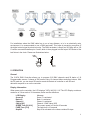
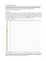
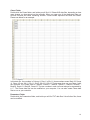
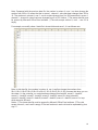
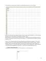
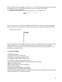
1
1. INTRODUCTION AND UNPACKING
Thank you for purchasing the MICROH DMX DICTATOR 512 controller. For your own safety and
knowledge, please read this manual before installing or operating the device. This manual covers
the important information on installation and applications. Please install and operate the fixture
according to instructions. Meanwhile, please keep this manual for future reference.
The MICROH DICTATOR 512 DMX controller is manufactured following CSA standards,
complying with international standard DMX512 protocol. This controller is applicable but not limited
to large-scale live performances, theater, studio, nightclubs and discos.
The MICROH DMX DICTATOR 512 controller features a two colour laser, strobe and a
moonflower effect. Please carefully unpack it when you receive the fixture and check if it was
damaged during the transportation. Please check whether the following items are included inside
the box:
Controller – One
Power Adapter – One
SD card - One
User Manual – One
2. SAFTEY INSTRUCTIONS
This device has been delivered in safe working condition. In order to maintain this condition and to
ensure safe operation, it is absolutely necessary for the user to follow the safety instructions and
warning notes written in this user manual.
If the device has been exposed to temperature changes, do not switch it on immediately. The
arising condensation could damage the device. Leave the device switched off until it has reached
room temperature, and is dry.
This device falls under protection-class I, therefore it is essential that the device be grounded. The
electrical connection must be carried out by a qualified technician.
The device should only be used with rated voltage and frequency. Make sure that the available
voltage is not higher than 120V as stated at the end of this manual.
Make sure the power cord is never crimped or damaged in any way, as this could cause shock and
damage. If your power cord is damaged in any way, please purchase a new cable from your local
MICROH dealer. Always disconnect power, when the device is not in use or before cleaning it.
Never pull out the plug by tugging the power cord.
2
Fixtures cannot be installed on or near combustible substances. Keep more than 50cm distance
from wall for proper ventilation and air flow. If your fixture is or has become damaged in any way, it
shall be exclusively replaced or repaired by the manufacturer to avoid any hazard.
3. CONTROLS AND FUNCTIONS
1. Scene Buttons (1-16) - Press the scene buttons to load or stored your scenes, there are
maximum of 480 programmable scenes.
2. Faders - These faders are used to control the intensity of channel 1-16 or channel 17-32
depending upon the selected page.
3
3. Fixtures Buttons (1-16) - Press the fixtures buttons to turn on/off fader control of
corresponding channels.
Example: Press fixture 1 button, the corresponding LED on to turn on fader control of
channels 1-32; press fixture 1 button second time, the corresponding LED off to turn off fader
control of channels 1-32.Press fixture 2 button, the corresponding LED on to turn on fader
control of channels 33-64; press fixture 2 button second time, the corresponding LED off to
turn off fader control of channels 33-64.
4. Add button - Used to store scene or chase.
5. MIDI button -Page Select Button - Used to select page between page A(1-16) and page B
(17-32).
6. Pan Joystick - This joystick is used to control the Pan of the fixture or for programming
7. Speed Slider - Used to adjust the scene or chase speed within the range of 0.1 second to 10
minutes.
8. Fade Time Slider - Used to adjust the scene or chase fade time within the range of 0 second
to 30 seconds. 0 second is off fade function.
9. Tilt Joystick - This joystick is used to control the tilt of the fixture or for programming.
10. SD card slot - This SD card slot is used to insert SD card record whole data of controller.
11. Prog Button - Activates program mode.
12. Chase Button (1-6) - These buttons are used for activating the chase of programmed scenes.
13. Blackout Button - Press this button to pause whole output.
14. LCD Display - Shows the current activity or programming state.
15. Del button - Used to delete scene or chase.
16. Bank Up/Down - Press the Up/Down button to select from 30 banks.
17. Auto button - Used to activate auto mode to run scene or chase.
18. Tap sync button - Repeatedly tapping this button to establish the chase speed or check the
step in chase.
19. Sound button - Used to activate sound mode to run scene or chase.
20. Mode button - Used to set the pan and tilt address of the fixture.
1. DC Input - DC12V 500mA min.
2. Power Switch
3. DMX OUT
4. DMX-512 CONTROL CONNECTIONS
This fixture complies with international USITT DMX standards and can be used with either a 3 pin
or 5 pin DMX connector. Plug in the provided 3 pin XLR cable to the female 3-pin XLR output of
your controller and the other side to the male 3-pin XLR input of the DICTATOR512. To connect
the units to DMX, you must daisy chain the fixtures together as referred in the diagram below.
Always end your DMX-512 connection with a DMX terminator.
4
For installations where the DMX cable has to run a long distance, or is in an electrically noisy
environment, it is recommended to use a DMX terminator. This helps in preventing corruption of
the digital control signal by electrical noise. The DMX terminator is simply an XLR plug with a 120
ȍUHVLVWRUFRQQHFWHGEHWZHHQSLQVDQGZKLFKLVWKHQSOXJJHGLQWRWKHRXWSXW;/5VRFNHWRIWKH
last fixture in the chain. Please see illustrations below.
120¡
2
3
1
PIN 3
PIN 2
5. OPERATION
General
The 512CH DMX Controller allows you to program 512 DMX channels each.30 banks of 16
Programmable scenes, 6 chases of 480 scenes using 16 channel sliders and other buttons. With
the SD card slot, you can insert SD-card to record whole data of controller or edit SD-card
data with computer to run on the controller.
Display Information
When power on the controller, the LCD displays "WiFly WLC16 V1.0".The LCD Display contains a
maximum of 2 lines each of 16 characters, below are the definitions
LCD Display
Scene=01
Bank=01
Chase=01
CH01=[255]
SPEED Time:[05:30.0]
FADE Time:[15.0]
Step020
Message
Scene 1 is activated
Bank 1 is activated
Chase 1 is activated
Channel 1 DMX Value (255)
The current speed is 5 minute 30 seconds
The fade time is 15 seconds
Step 20 is activated or the chase contains 20 steps
5
6. SET UP
Unit Setup
The unit is preset to allocate 32 channels per fixture, in order to assign your fixtures to the fixture
buttons located on the left side of the unit you will need to space your fixtures 32 DMX channels
apart.
Enabling the program mode
1) Press and hold down the PROG button until the LCD displays "Password:"
2) Tap the Scene buttons 8,8,8 and 8.
3) Tap the ADD button, the PROG LED lights up, now you can begin to program.
NOTE:
The first time you turn on your unit, the default setting of the PROG Code
is Scene buttons 8, 8, 8 and 8.You may change the PROG Code to protect your programs.
Security for Your Programs
To protect your programs from editing by others. You may change the PROG Code.
1) Turn off the controller. Press and hold down the PROG button.
2) Turn the controller back on until the LCD displays "Old Password:", tap the Scene buttons 8,8,8
and 8(if you have changed the PROG Code, please tap the modified PROG Cord)
3) Tap the ADD button, the LCD displays "Set Password". Tap the desired Scene button to enter a
new PROG Code. The PROG Code consists of 4 Scene buttons (the same button or different
buttons), be sure your new PROG Code consists of 4 Scene buttons.
4) Tap the ADD button. If the LCD displays "Saved" means the new PROG Code has been
successfully stored, if the LCD displays "Saved fail" means the new PROG Cord store failed.
5) Exit PROG mode. Press and hold down the PROG button until the PROG LED lights off, the
PROG mode is engaged.
!!!IMPORTANT!!!
If you don't remember your new PROG Code, Scene buttons 9,9,9 and 9 is the universal code.
You can tap in these PROG cord to enable the program anytime even if you don't remember the
new PROG Code.
Set-up Joystick
3. Enter program mode (See Enabling Program Mode)
4. Press the MODE button, the MODE LED lights up, the controller enter joystick set up mode.
5. Tap the bank Up/Down button to select the axis you wish to assign (Pan or Tilt)
6. Tap the desired Scene buttons to assign a channel address to the desired axis you have
selected. The address consists of 3 Scene buttons from 000-512(the same button or different
buttons).The Scene button 10 indicates 0.
7. Press the ADD button. If the LCD displays "Saved" means the axis address has been
successfully stored, if the LCD displays "Saved fail" means the axis address store failed.
8. Press MODE to exit joystick set up mode.
6
7. SCENES
Programming a Scene
1) Enter program mode (See Enabling Program Mode)
2) Check the blackout key and verify that the LED is not lit, if it is press it once to exit blackout
mode.
3) Press the fixtures button corresponding to the unit wish to control. You may control more than
one fixture at time by pressing the button corresponding to the fixture(s) you wish to program.
4) Move the faders to the desired position. If necessary, you may select page B to control channels
17-32.
5) Tap the bank Up/Down button to choose the bank you want to store this scene into. There are a
total of 30 banks that you can select, you may store up to 16 scenes in each bank. In each bank,
the scenes buttons that contain data will light ON solid green. This lets the user know that there is
a scene already programmed there.
6) Tap the ADD button.
7) Tap the scene button you wish to store you scene into. The LCD readout will show the bank and
scene. If the LCD displays "Saved" means the scene have been successfully stored, if the LCD
displays "Saved fail" means the scene store failed If a scene button, that already includes scene
data, is selected, the LCD displays "Overwrite". If the user wants to overwrite the previous data,
press ADD button and then the LCD displays "Saved" means the scene have been successfully
stored; if the user doesn't want to overwrite, press DEL button and the LCD display will return to
the previous screen.
Example Scene Program
1) Enter program mode (See Enabling Program Mode)
2) Tap the Fixtures button to turn on its fader control.
3) Verify that the page select is set on page A, if not press the page select button to select page A
4) Move the first and second faders all the way up to their maximum position.
5) Select bank 1 using the bank Up/Down buttons. In bank 1,the scenes buttons that contain data
will light ON solid green. This lets the user know that there is a scene already programmed there.
6) Press the ADD button.
7) Tap scene 1 to store the first scene. The LCD displays "Saved" means the scene have been
successfully stored. If scene 1 already includes scene data, the LCD displays "Overwrite", press
ADD button and then the LCD displays "Saved" means the scene have been successfully stored
Deleting A Scene of a bank
1) Enter program mode (See Enabling Program Mode).
2) Tap the bank Up/Down button to choose the bank you want to delete this scene. In each
bank, the scenes buttons that contain data will light ON solid green. This lets the user know that
there is a scene already programmed there.
3) Press the desired Scene button to select the scene you wish to delete.
4) Press DEL button. If the LCD displays "Deleted Success" means the scene have been
successfully deleted, if the LCD displays "Deleted fail" means the scene delete failed.
Deleting all Scenes of a bank
1) Enter program mode (See Enabling Program Mode).
2)Tap the bank Up/Down button to choose the bank you want to delete all the scenes.
3) Press DEL button. If the LCD displays "Deleted success" means all scenes of the bank have
been successfully deleted, if the LCD displays "Deleted fail" means all scenes of the bank delete
failed.
7
Deleting All Scenes
1) Enter program mode (See Enabling Program Mode).
2) Use the Bank Up/Down button to choose any one of the bank
3) Tap any one of scene button to set to scene 0.
4) Press and hold the DEL button for about 15 seconds. If the LCD
Displays "Deleted success" means all the chases have been successfully deleted, if the LCD
displays "Deleted fail" means all the scenes delete failed.
8. CHASES
Note: You must have already programmed scenes in order to program a chase, this function
allows you to cycle through up to 480 scenes in a preselected order. It is recommended before
programming chases for the first time you delete all chases in the controller. See Delete All
Chases for instructions on how to do so.
Copy a Scene of a Bank to a Chase
1) Enter program mode (See Enabling Program Mode).
2) Tap the Chase button to select the chase wish to program. The LCD will display how many
steps have already stored in the chase if the chase already has been programmed.
3) Tap the bank Up/Down button to choose the desired bank that has scenes stored inside it. In
each bank, the scenes buttons that contain data will light ON solid green. This lets the user know
that there is a scene already programmed there.
4) Press the desired Scene button to select the scene you wish to copy it to the desired chase.
5) Tap the ADD button. If the LCD displays "Saved" means the chase have been successfully
stored, if the LCD displays "Saved fail" means the chase store failed.
6) Repeat steps 3-5 until all desired scenes have been entered.
Copy All Scenes of a Bank to a Chase
1) Enter program mode (See Enabling Program Mode).
2) Tap the Chase button to select the chase wish to program.
3) Tap the bank Up/Down button to choose the desired bank that has scenes stored inside it. In
each bank, the scenes buttons that contain data will light ON solid green. This lets the user know
that there is a scene already programmed there.
4) Tap the ADD button. If the LCD displays "Saved" means the chase have been successfully
stored, if the LCD displays "Saved fail" means the chase store failed.
5) Repeat steps 3-4 until all desired scenes have been entered.
Add a Step
1) Enter program mode (See Enabling Program Mode).
2) Tap the Chase button to select the desired chase you wish to add a step to. The LCD will
display how many steps have already stored in the chase.
3) Tap the Tap sync button.
4) Tap the bank Up/Down button to scroll to the step which you wish to insert the step after. You
can read the step from the LCD Display.
5) Tap the ADD button.
6) Tap the bank Up / Down button to choose the desired bank that has the desired scene stored
which you wish to add. In each bank, the scenes buttons that contain data will light ON solid green.
This lets the user know that there is a scene already programmed there.
7) Press the desired Scene button to select the scene you wish to add.
8
8) Tap the ADD button. If the LCD displays "Saved" means the step have been successfully
added, if the LCD displays "Saved fail" means the step add failed.
EXAMPLE: Add scene 2 of bank 3 between step 4 and 5 of chase 5.
1) Enter program mode (See Enabling Program Mode).
2) Tap Chase 5 button. The LCD will display how many steps have already stored in chase 5.
3) Tap the Tap sync button.
4) Tap the bank Up/Down button to select step 4.You can read the step from the LCD Display.
5) Tap the ADD button.
6) Tap the bank Up/Down button to choose bank 3.The scenes buttons that contain data will light
ON solid green in bank 3.This lets the user know that there is a scene already programmed there.
7) Press Scene 2 button to select the scene 2.
8) Tap the ADD button. The LCD displays "Saved" means the step have been successfully added.
Now the scene 2 of bank 3 is the new step 5,the previous step 5 turns to the new step 6,the
previous step 6 turns to the new step 7 and so on.
Delete a Step
1) Enter program mode (See Enabling Program Mode).
2) Tap the Chase button to select the desired chase you wish to delete a step. The LCD will
display how many steps have already stored in the chase.
3) Tap the Tap sync button.
4) Tap the bank Up/Down button to scroll to the step which you wish to delete. You can read the
step from the LCD Display.
5) Tap the DEL button. If the LCD displays "Deleted success" means the step have been
successfully deleted, if the LCD displays "Deleted fail" means the step deleted failed.
EXAMPLE: Delete step 3 of chase 4.
1) Enter program mode (See Enabling Program Mode).
2) Tap Chase 4 button. The LCD will display how many steps have already stored in the chase.
3) Tap the Tap sync button.
4) Tap the bank Up/Down button to select step 3. You can read the step from the LCD Display.
5) Tap the DEL button. The LCD displays "Deleted success" means step 3 has been successfully
deleted. Now the previous step 4 turns to the new step 3,the previous step 5 turns to the new step
4 and so on.
Delete a Chase
1) Enter program mode (See Enabling Program Mode).
2) Press the button corresponding to the chase you wish to delete.
3) Press the DEL button. If the LCD displays "Deleted success" means the chase have been
successfully deleted, if the LCD displays "Deleted fail" means the chase delete failed.
Delete all Chase
1) Enter program mode (See Enabling Program Mode).
2) Press the any one of chase button.
3)Tap any one of scene button to set to scene 0.
4) Press and hold the DEL button for about 15 seconds. If the LCD displays "Deleted success"
means all the chases have been successfully deleted, if the LCD displays "Deleted fail" means all
the scenes delete failed.
9
9. TAP SYNC
This button has 2 functions, to set the speed time in auto mode and to check the step in chases.
Set Speed in Auto Mode
1) The Tap Sync button is used to set and synchronize the speed time by tapping the button
several times. The speed time will synchronize to the time of the last two taps. The speed time
may be set anytime whether or not a program is running
2) Tap Sync will override any previous setting of the speed slier control until the slider is moved
again.
3) Use of Tap Sync in setting a standard beat is the same with speed control slider.
Check Step in Chases
1) Enter program mode (See Enabling Program Mode).
2) Tap the Chase button to select the desired chase you wish to check. The LCD will display how
many steps have already stored in the chase.
3) Tap the Tap sync button.
4) Tap the bank Up/Down button to scroll to the step you wish to check. You can read the step
from the LCD Display.
10. PLAYBACK
Running Scenes
There are three modes in which you can run scenes. They are Manual mode, Auto mode, and
music mode.
Manual Mode
1) When the power is turned on, the unit enters manual mode automatically.
2) Check and verify that both the Auto and Music LEDs are off.
3) Use the Bank Up / Down button to select the bank with the scenes you wish to run.
4) Press the scene button corresponding to the scene you wish to display.
Auto Mode
This function allows you to run a bank of programmed scenes in sequence.
1) Press the AUTO button to enter into Auto mode The Auto LED will light indicating the Auto
mode is active.
2) Use the bank Up / Down button to select a bank of scenes to run. If the bank of scene has no
data, the LCD displays "Empty".
3) After selecting the bank of scenes to run, you can use the speed slider or tap the Tap Sync
button twice to adjust the speed, use Fade Time slider to adjust fade time of the scene
progression.
4) Tap the AUTO button to exit Auto mode.
10
Music Mode
1) Press the SOUND button to activate Music mode.
2) Use the bank Up/Down button to select a bank of scenes you will to run the scenes selected will
run through sequentially the beat of the music identified by the built-in microphone
3) Use the Fade time slider to adjust the fade time of the scene progression.
4) Tap the SOUND button to exit music mode.
Running Chases
There are three modes in which you can run chases. They are Manual mode, Auto mode and
music mode.
Manual mode
1) When the power is turned on, the unit enters manual mode automatically.
2) Check and verify that both the Auto and Music LEDs are off.
3) Select the desired chase by pressing one of six Chase buttons with the bank you wish to run.
4) Use the Bank Up/Down button to select the bank with the scenes you wish to run.
5) Press the scene button corresponding to the scene you wish to display.(If more than one scene
button have been pressed, he controller will play the scene with bigger number)
Auto Mode
1) Press the AUTO button to activate Auto mode
2) Select the desired by pressing one of six Chase buttons. Pressing this button a second time will
negate this selection. If the chase has no data, the LCD displays "Empty".
3) Use the speed slider or tap the Tap Sync button twice to adjust the speed, use Fade Time slider
to adjust fade time of the scene progression.
4) Tap the AUTO button to exit Auto mode.
Music Mode
1) Press the SOUND button to activate Music mode.
2) Select the desired chase by pressing one of six Chase buttons this will activate the chase and
cause it to respond to the rhythms of music.
3) Use the Fade time slider to adjust the fade time of the chase progression.
4) Tap the SOUND button to exit music mode
11. SD card
General:
With the SD-card slot, you can insert SD-card to record whole data of controller .You can also edit
the data of SD-card with computer then insert the SD-card into the SD-card slot of the controller to
run the data which contains scenes and chases.
SD-card request
The SD-card capacity is 4G max and the format of the SD-card must be FAT or FATS. When SDcard is the first time be used, you must format it.
11
Record data of controller
Insert the SD card into the controller SD card slot, it will automatically create a corresponding data
file with the wifly radio channel, speed time, password, scene, Bank, and chase that have been
successfully saved on controller. With the data file created, open the SD card data with computer,
you will find three folders; a Bank folder, Chases folder and Parameters folder.
NOTE: All of these folders can be edited
Bank Folder
If you double click the Bank folder you will see 1-30 Bank subfolder, depending how many Banks
you have successfully saved on the controller. Double click one of the subfolders and you will see
XLS data file ranging from Scenes01.xls to Scenes16.xls, depending how many scenes you have
successfully saved to on the controller into that corresponding Bank. Double click the Scene data
file and you will find 512 cells in Column A, rows 1-512. Depending on the how many Scenes you
have saved, the rows will Channel value of the Scene saved to the controller.
See below for an example.
In this data file, the number in Column A, Row 1 is 255, and Rows 2-512 are 0. This means that in
Scene 1, Channel 1 value is set at 255, and Channels 2-512 values are 0. The Scene data files
can be modified on your computer. You can also create Scene data files to run on your controller.
All data files must be opened Microsoft Office Excel software.
12
Chase Folder
Double click the Chase folder, and inside you will find 1-6 Chase XLS data files, depending on how
many chases you have stored on the controller. When you open one of the chase data files you
will find Columns and Rows containing number. These number represent the Bank and Scene.
Please see below for an example.
In this data file, the numbers in Column A, Row 1 is 29+11, those numbers mean Bank 29, Scene
11. Rows 1-5 are, 29+11; 26+11; 29+07; 26+13; & 26+15. That means when you run Chase 1 with
the controller, the Chase order is, Bank29, Scene11 - Bank26, Scene11 - Bank29, Scene07 Bank26, Scene13 - Bank26, Scene15. The two numbers in each cell must always be separated by
a “+”. The Chase data files can be modified on your computer. You can also create Chase data
files to run on your controller.
Parameters Folder
Double click the Parameters folder, and inside you will find TXT data files. Like all other files, these
can be modified.
13
Password.TXT
Double click the Password.TXT data file, and you will find numbers ranging from 0000-9999,
depending on the password you have successfully saved to the controller. For example, the below
screenshot shows 1111, that means the password that was successfully saved to the controller is
1111.
Speed Time.TXT
Double click the Speed Time.TXT data file, and you will find numbers ranging from 0001-6000,
depending on the speed time you have successfully saved to the controller. For example, the
below screenshot shows 0523, that means that you have set the speed time to 52.3 seconds.
14
ROTARY
Double-click the Rotary.TXT data file, you can find two numbers separated by plus sign "+" from
001-512 depending on the Pan and Tilt axis channel addresses you have successfully saved on
controller.
For example, we open Rotary.TXT data file, it is as follows:
Note: In this data file, the number 003 means you have set the Pan axis channel address to 3;the
number 009 means you have set the Tilt axis channel address to 9.
Edit data file with computer to run on controller
You can also modify or create the scene and chase XLS date file with computer to run on the
controller for convenient use.
(1) Modify scene and chase data file
For example, we modify scene 1data file in bank 1 subfolder and save it, it is as follows now:
15
Note: Compared with the previous data file, the number in column A, row 1, we have change the
number from 255 to 12 means that the in scene 1, channel 1 value has been changed from 255 to
12. The numbers in column A, row 2 - row 4 we have change from 0 to 255 means that in scene 1,
channel 2 - channel 4 values has been changed from 0 to 255. Notice: ķThe scene data file must
be opened by Microsoft Office Excel software. ĸThe cells except column A, row1 – row 512 is
empty.
For example, we modify chase 1 data file in chase folder and save it, it is as follows now:
Note: In this data file, the numbers in column A, row 1-row5,we change the numbers from
29+11;26+11;29+07;26+13;26+15 to 26+15; 26+13;29+07;26+11;29+11means that when you run
the chase 1 in the controller, run order has been changed from bank29, scene11ĺEDQN26,
scene11 ĺEDQN29, scene07ĺEDQN26, scene13ĺEDQk26, scene15 in loop to bank26,
scene15ĺEDQN26, scene13ĺEDQN29, scene07ĺEDQN26, scene11ĺEDQN29, scene11 in loop
which stored in SD-card.
Notice: ķThe chase data file must be opened by Microsoft Office Excel software. ĸThe cells
except column A, row1-row5 is empty.eThe two numbers in each cell must be separated by plus
sign "+".
16
(2) Create scene and chase data file. For example, we create scene 2 XLS data file in bank 15
subfolder and save it, it is as follows:
Note: In this data file, in column A, row1-row512 must all fill in numbers separately. The numbers
must be in the range of 0-255.Each number in the cell represent the corresponding channel value.
Cell of column A, row 1 number is 4 means channel 1 value is 4.Cell of column A, row 2 number is
56 means channel 2 value is 56 and so on.
Notice: ķThe chase data file must be opened by Microsoft Office Excel software. ĸThe cells
except column A, row1-row6 is empty.eWe must name scene 2 data file to "Scenes02" and so on.
We can create scene 1 to scene 16, total 16 scenes max in one bank.
17
For example, we create chase 2 data file in chase folder and save it, it is as follows:
Note: In this data file, the numbers in column A, row 1-row4 is 29+05;30+05;01+11;05+15 means
that when you run the chase 2 on controller, run order is from
bank29,scene05ĺbank30,scene05ĺbank01,scene11ĺbank05,scene15 in loop which stored in
SD-card. The first two numbers must be in the range of 1-30, the second two numbers must be in
the range 1-16.
Notice: ķThe chase data file must be opened by Microsoft Office Excel software. ĸThe cells
except column A, row1-row6 is empty.ebank29, scene05; bank30, scene05; bank01, scene11;
bank05, scene15 must have been stored in the SD-card. We must name chase 2 data file to
"Chases02" and so on. We can create chase 1 to chase 6, total 6 chases max. The two numbers
in each cell must be separated by plus sign "+". Each chase contains 480 steps max.
(3) Modify password data file
For example, we modify Password.TXT file and save it, it is as follows now:
18
Note: In this data file, we change the number from 1111 to 2356 means that when we have change
the password from 1111 to 2356.The number must be in the range of 0000-9999.
(4) Modify speed time data file
For example, we modify Speed Time.TXT file and save it, it is as follows now:
Note: In this data file, we change the number from 0523 to 0931 means that we have change the
speed time from 52.3 seconds to 93.1 seconds. The number must be in the range of 0001-6000.
(5) Modify rotary data file
Note: In this data file, we change the number from 003 to 136 means that we have change the Pan
channel address from 3 to 126,we change the number from 009 to 498 means that we have
change the Tilt channel address from 9 to 498.The number must be in the range of 001-512. The
two numbers must be different.
12. KEY FEATURES
Ɣ 512DMX channels
Ɣ 16 Fixtures of 32 channels each
Ɣ 30 Banks of 16 programmable scenes
Ɣ 6 Programmable chases of 480 scenes
Ɣ 16 Sliders for manual control of channels
Ɣ Auto mode program controlled by speed and fade time sliders
Ɣ Blackout master button
Ɣ Built-in microphone for music triggering
Ɣ Power failure memory
Ɣ Assignable joystick for ease of channels
Ɣ 16x2 character LCD display with backlight.
Ɣ6'-card slot provided. Each SD-card can record whole data of controller or edit SD-card
data with computer to run on the controller.
19
13. TECHNICAL SPECIFICATIONS
Power Input
DMX Out
Dimensions
Weight
DC12V 500mA min
3 pin female XLR socket
482x200x74mm
3.1kgs
14. MAINTENANCE AND CLEANING
The following points have to be considered during the inspection:
1) All screws for installing the device or parts of the device must be tightly connected, and must
not be corroded.
2) There must not be any deformations on the housing, colour lenses, fixations or installation
spots (ceiling, suspension, trussing).
3Mechanically moved parts must not show any traces of wearing and must not rotate with
unbalances.
4㸧The electric power supply cables must not show any damage, material fatigue or sediments.
Further instructions depending on the installation spot and usage must be handled by a skilled
installer or technician. Any safety issues must be resolved.
In order to keep the fixture in good condition and extend the life, we suggest regular cleaning to
the fixture.
1) Clean the inside and outside lens each week to avoid the light output from darkening due to
accumulation of dust, dirt, etc.
2) Clean the fan each week.
3) A detailed electrical check by approved technician every three months is advised. Ensure the
circuit contacts are in good condition.
We recommend a frequent cleaning of the device. Please use a moist, lint- free cloth. Never use
alcohol or solvents.
There are no serviceable parts inside the device. Please refer to the instructions under “Installation
instructions”.
Should you need any spare parts, please order genuine MICROH parts from your local dealer.
20
IF YOU SHOULD EXPERIENCE ANY PROBLEMS OR ISSUES PLEASE CONTACT MICROH
PROFESSIONAL PRODUCTS BY EMAIL AT [email protected]
In the event that your unit is defective in any way, please contact your local dealer to obtain
an RA number for service repair.
DISCLAIMER – MICROH believes that the information contained within this user manual is
accurate. However, Microh is not responsible for any error or addendums to this manual. If
you have any comments or general suggestions on how this manual can be improved
please contact [email protected]. Thank you.
21
NOTES:
22