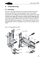
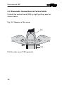
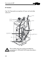
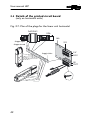
1
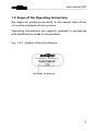
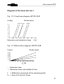
USER MANUAL Handling Components Linear Unit LEP BA-100015 ENGLISH Edition:12/2005 ® User manual LEP Revision index Published expenditures: Edition: Notice Ref.No. 05/1995 first edition 504576 10/1995 505388 02/1996 505399 03/1998 505971 08/1998 506065 04/1999 506168 04/2004 508463 12/2005 2 Various adjustments BA-100015 ® User manual LEP Directory 1 1.1 1.2 1.3 1.4 1.5 1.6 1.7 1.8 1.9 Important information .................................................. 5 Manufacturer’s declaration ................................................5 Scope of the Operating Instructions .................................7 Technical Data of Horizontal Units size 1 ..........................8 Dimensional drawing linear unit size 1 ............................14 Technical Data of Horizontal Units size 2 ........................16 Dimensional drawing linear unit size 2 ............................21 Technical data of the linear unit vertically .......................24 Dimensional drawing linear unit vertically .......................30 Points of Action of Forces and Torques ..........................32 2 2.1 2.2 2.3 2.4 2.7 2.8 2.9 Commissioning ........................................................... 33 Assembly ..........................................................................33 Pneumatic Connection to Horizontal Units .....................34 Pneumatic Connection to Vertical Units ..........................38 Details of the printed circuit board (only on horizontal units) .................................................................................42 Setting the mechanical end-stops....................................43 Setting the Shock-Absorbers (see Fig. 5.1–1 / 5.1–2 / 5.3– 1 / 5.3–2)...........................................................................46 Connecting the Inductive Proximity Switches .................48 Setting the inductive proximity switches.........................50 Mounting the Protective Covers......................................51 3 3.1 3.2 3.3 Maintenance ............................................................... 52 Oiling the Felt Pads and Felt Wicks.................................52 Lubrification......................................................................53 Inspecting the shock-absorbers.......................................54 2.5 2.6 4 Repairs ....................................................................... 54 4.1 Replacing the Main Cylinder ............................................54 3 ® User manual LEP 4.2 Replacement of a proximity switches ..............................56 4.3 Replacing Shafts and Rollers............................................58 4.4 Setting the slide play........................................................61 5 5.1 5.2 5.3 5.4 Exploded drawings / Spare parts lists ....................... 62 Exploded drawing linear unit horizontal..........................62 Partial list linear unit horizontal, version A and B ............66 Exploded drawing linear unit vertically ...........................76 Partial list linear unit horizontal, version A and B ............80 6 Environmental Compatibility...................................... 84 7 List of figures ............................................................. 86 4 ® User manual LEP 1 Important information EC Declaration of Conformity (see MRL Appendix II A) 1.1 Manufacturer’s declaration Rules and standards complied with: Machinery guidelines 89/392 EWG, 91/368/EWG Manufacturer MONTECH AG Gewerbestrasse 12 CH-4552 Derendingen Tel. +41 (0) 32 681 55 00 Fax. +41 (0) 32 682 19 77 Purpose Linear units LEP are used where regular, linear movements in either the forward or reverse direction are required, primarily in a horizontal or vertical plane, e.g. as in automatic material handling. Under all circumstances attention must be paid to the performance limits, as given in the technical data. Correct setting of a device to the factors influencing a particular application guarantees optimal performance, operation free from faults and a long useful life. Hazards The use of linear units LEP in an installation is only permissible when they are guarded by MOVING, ISOLATING PROTECTIVE DEVICES as per EN 292-2, para.4.2.2.3. Failure to comply with this protective measure can result in injury due to squeezing or impact, especially when automatically starting machines are involved. 5 ® User manual LEP Never allow a unit to run without its side cover in position! Additional information The aim of the present operating instructions is to enable users to employ linear units LEP correctly and safely.Should further information be required relating to the particular application, do not hesitate to contact the manufacturer. When ordering user manual it is essential to quote the type and serial number. Fig. 1-1: Nameplate Bar code 42425 Order number Serial number Montech AG Management U. D. Wagner 6 C. Wullschleger ® User manual LEP 1.2 Scope of the Operating Instructions We adapt our products constantly to the newest state of the art and the realizations from practice. Operating instrsuctions are regularly updated in accordance with modifications made to the products. Fig. 1.2–1: Validity of the User Manual Number of edition 7 ® User manual LEP 1.3 Technical Data of Horizontal Units size 1 Stroke (min. / max.) Stroke, step range Dia. of piston- Ø / dia. of piston rod - Ø Outward / inward force at 5 bar Max, permissible additional mass m adm. 1) [mm] [mm] [mm] [N] [kg] Fz adm. 2) [N] FY adm. 2) [N] (Fz · LY) adm. 2) [Ncm] Weight Operating pressure Operating medium Damping in end positions Repeatability Check of end positions Plug-in pneumatic connection Speed regulation Noise level Degree of protection Lead between control system and LEP Connection capacity of printed circuit board Ambient: Temperature Rel. humidity Air purity Guaranty period Maintenance Material 8 [kg] [bar] 3) 4) 5) 6) [mm] [dBA] [°C] ® User manual LEP LEP90-1A LEP 90-1B LEP 160-1A LEP 160-1B LEP 225-1A LEP 225-1B 15/90 – 16/6 88/76 8 130 70 1200 2.5 15/90 0–80 16/6 88/76 8 190 100 1200 3.1 15/160 – 16/6 88/76 8 95 50 1200 3.2 15/160 0–100 16/6 88/76 8 155 85 1200 3.8 15/225 – 16/6 88/76 8 160 85 1200 4.5 15/225 0–100 16/6 88/76 8 160 85 1200 4.6 3-6 air, oiled or unoiled, filtered to 5µm, dew point <6°C hydraulic shock-absorbers with fine adjustment < 0.005 inductive proximity switches main cylinder: hose-Ø 4 mm variable stop: hose-Ø 4 mm adyustable exhaust throttles M5 < 64 IP 42 max.17-core incl. 0 V and 24 V, 0.14-0.5 mm2 for 15 proximity switches 10-50 < 95% (without condensation) normal workshop atmosphere 2 years from the date of delivery oiling the felt pads and rods aluminium, steel, bronze, plastic 9 ® User manual LEP 1) Difference between the two extended strokes 2) The values quoted for Fz, Fy and Fz LY apply to the entire stroke range 3) Scatter of the end setting during 100 successive strokes, conditions as 6) 4) With LED visible from outside The pneumatically actuated variable stop has fixed throt5) tles 6) Measured at 5 bar, maximum stroke, with attached mass m = 6.5 kg and fully open throttles 10 ® User manual LEP Diagrams of the linear unit size 1 Fig. 1-2: Travel time diagram LEP-90-1A/B m [kg] Stroke [mm] 30 30 60 60 8 90 90 7 6 5 4 3 2 1 0 0 0.05 0.1 0.15 0.2 0.25 0.3 Extension and retraction times 0.35 t [s] Fig. 1-3: Deformation diagram LEP-90-1A/B f [mm] 0.10 0.08 0.06 0.04 0.02 0 Stroke [mm] 90 60 30 0 20 40 60 80 100 120 140 160 180 Fz [N] - - Extension time --- Retraction time unthrottled at 5 bar f = Deflection (measured at the clamping plate) Fz = Sum of all vertical forces 11 ® User manual LEP Fig. 1-4: Travel time diagram LEP-160-1A/B m [kg] Stroke [mm] 40 8 80 80 40 120 160 160 7 6 5 4 3 2 1 0 0.05 0.1 0.15 0.2 0.25 0.3 0.35 Extension and retraction times 0.4 0.45 t [s] Fig. 1-5: Deformation diagram LEP-160-1A/B f [mm] 0.18 0.16 0.14 0.12 0.10 0.08 0.06 0.04 0.02 0 Stroke [mm] 160 120 80 40 0 20 40 60 80 100 120 140 160 Fz [N] - - Extension time --- Retraction time unthrottled at 5 bar f = Deflection (measured at the clamping plate) Fz = Sum of all vertical forces 12 ® User manual LEP Fig. 1-6: Travel time diagram LEP-225-1A/B m [kg] Stroke [mm] 75 75 175 225 125 225 8 7 6 5 4 3 2 1 0 0.1 0.15 0.2 0.25 0.3 0.35 0.4 0.45 0.5 0.55 Extension and retraction times t [s] Fig. 1-7: Deformation diagram LEP-225-1A/B f [mm] 0.22 0.20 0.18 0.16 0.14 0.12 0.10 0.08 0.06 0.04 0.02 0 Stroke [mm] 225 175 125 75 0 20 40 60 80 100 120 140 160 Fz [N] - - Extension time --- Retraction time unthrottled at 5 bar f = Deflection (measured at the clamping plate) Fz = Sum of all vertical forces 13 ® User manual LEP 1.4 Dimensional drawing linear unit size 1 Fig. 1-8: Dimensional drawing linear unit size 1 33 Fz 115 66 90°±0.05 24.5 90°±0.05 Beff Aeff 10 D 125 700 C PG 29 Ly 62 31 31 20 20 5 Fz Operating side to adjust the stroke Fy E N M V V H H L Option with power supply chain 14 Standard with protective hose ® User manual LEP horizontal Amax Bmax C D E L M N LEP-90-1A 90 – 30-120 208 175 150 770 450 LEP-90-1B 90 80 30-120 265 175 150 820 460 LEP-160-1A 160 – 30-190 277 175 150 850 490 LEP-160-1B 160 100 30-190 345 175 150 900 500 LEP-225-1A 225 – 30-255 475 175 150 1170 590 LEP-225-1B 225 100 30-255 475 175 150 1170 590 Aeff Setting range of the first position (Amax ≥ Aeff ≥ 15) Beff Set difference in stroke between 1st and 2nd positions (Beff ≤ Bmax and Beff ≤ Aeff –10)*) Distance from body to end face of clamping plate (doveC tail) D Mounting range (dovetail) Maximum height of the power supply chain above the E body L Maximum projection of the power supply chain M Necessary extended length of protective hose from a vertical axis to the horizontal axis N Maximum height of protective hose above the body *) Both conditions must be fulfilled 15 ® User manual LEP 1.5 Technical Data of Horizontal Units size 2 Stroke (min. / max.) Stroke, step range Dia. of piston- Ø / dia. of piston rod - Ø Outward / inward force at 5 bar Max, permissible additional mass m adm. 1) [mm] [mm] [mm] [N] [kg] Fz adm. 2) [N] FY adm. 2) [N] (Fz · LY) adm. 2) [Ncm] Weight Operating pressure Operating medium Damping in end positions Repeatability Check of end positions Plug-in pneumatic connection Speed regulation Noise level Degree of protection Lead between control system and LEP Connection capacity of printed circuit board Ambient: Temperatur Rel. humidity Air purity Guaranty period Maintenance Material 16 [kg] [bar] 3) 4) 5) 6) [mm] [dBA] [°C] ® User manual LEP LEP320-2A LEP 320-2B LEP 450-2A LEP 450-2B 50/320 – 20/8 136/114 8 120 100 3850 8 50/320 0–150 20/8 136/114 8 190 160 3850 9.6 50/450 – 25/10 211/177 8 145 120 3850 10.5 50/450 0–150 25/10 211/177 8 145 120 3850 11 3-6 air, oiled or unoiled, filtered to 5µm, dew point <6°C hydraulic shock-absorbers with fine adjustment < 0.005 inductive proximity switches main cylinder: hose-Ø 4 mm variable stop: hose-Ø 4 mm adyustable exhaust throttles G⅛" < 64 IP 42 max.17-core incl. 0 V and 24 V, 0.14-0.5 mm2 for 15 proximity switches 10-50 < 95% (without condensation) normal workshop atmosphere 2 years from the date of delivery oiling the felt pads and rods aluminium, steel, bronze, plastic 17 ® User manual LEP 1) Difference between the two extended strokes 2) The values quoted for Fz, Fy and Fz LY apply to the entire stroke range 3) Scatter of the end setting during 100 successive strokes, conditions as 6) 4) With LED visible from outside The pneumatically actuated variable stop has fixed throt5) tles 6) Measured at 5 bar, maximum stroke, with attached mass m = 6 kg LEP-320-2 / 7.25 kg LEP-450-2 and fully open throttles 18 ® User manual LEP Diagrams of the linear unit size 2 Fig. 1-9: Travel time diagram LEP-320-2A/B m [kg] 8 7 6 5 4 3 2 1 0 Stroke [mm] 80 0 0.1 0.2 160 0.3 240 320 320 0.4 0.5 Extension and retraction times 0.6 t [s] Fig. 1-10: Deformation diagram LEP-320-2A/B f [mm] 0.28 0.24 0.20 0.16 0.12 0.08 0.04 0 Stroke [mm] 320 240 160 80 0 20 40 60 80 100 120 140 160 180 Fz [N] - - Extension time --- Retraction time unthrottled at 5 bar f = Deflection (measured at the clamping plate) Fz = Sum of all vertical forces 19 ® User manual LEP Fig. 1-11: Travel time diagram LEP-450-2A/B m [kg] Stroke [mm] 90 90 180 180 270 360 360 450 8 450 7 6 5 4 3 2 1 0 0 0.1 0.2 0.3 0.4 0.5 0.6 0.7 0.8 Extension and retraction times t [s] Fig. 1-12: Deformation diagram LEP-450-2A/B f [mm] Stroke [mm] 450 0.28 0.24 0.20 360 0.16 0.12 270 0.08 0.04 0 180 90 0 20 40 60 80 100 120 140 160 Fz [N] - - Extension time --- Retraction time unthrottled at 5 bar f = Deflection (measured at the clamping plate) Fz = Sum of all vertical forces 20 ® User manual LEP 1.6 Dimensional drawing linear unit size 2 Fig. 1-13:Dimensional drawing linear unit size 2 Fz 162 101 90°±0.05 Beff Aeff C 10 D 180 700 30.5 90°±0.05 PG 29 Ly 85 42.5 42.5 2020 15 Fz Operating side to adjust the stroke E Fy V H L Standard with power supply chain 21 ® User manual LEP horizontal Amax Bmax C D E L LEP-320-2A 320 – 32-352 500 175 150 LEP-320-2B 320 150 32-352 600 175 150 LEP-450-2A 450 – 32-482 725 175 150 LEP-450-2B 450 150 32-482 725 175 150 Aeff Setting range of the first position (Amax ≥ Aeff ≥ 50) Beff Set difference in stroke between 1st and 2nd positions (Beff ≤ Bmax and Beff ≤ Aeff –15)*) Distance from body to end face of clamping plate (doveC tail) D Mounting range (dovetail) Maximum height of the power supply chain above the E body L Maximum projection of the power supply chain *) Both conditions must be fulfilled 22 ® User manual LEP Notes: 23 ® User manual LEP 1.7 Technical data of the linear unit vertically Stroke (min./max.) Stroke, step range Dia. of piston-Ø/Dia. of piston-rod-Ø Outward / inward force at 5 bar Max. permissible additional mass madm. 1) [mm] [mm] [mm] [N] [kg] Fx adm. 2) [N] FY adml. 2) [N] (Fx · LY) adm. 2) [Ncm] Weight Operating pressure Operating medium Damping in end positions Repeatability Check of end positions Plug-in pneumatic connection Speed regulation Noise level Degree of protection Ambient: Temperatur Rel. humidity Air purity Guaranty period Maintenance Material 24 [kg] [bar] 3) 4) 5) 6) [mm] [dBA] [°C] ® User manual LEP LEP60-1A LEP 60-1B 15/60 – 16/6 15/60 0–50 16/6 5 150 80 1200 2.15 LEP 90-1A LEP 90-1B LEP 160-1A LEP 160-1B 15/90 15/90 15/160 15/160 – 0–80 – 0–100 16/6 16/6 16/6 16/6 see force diagram 5 5 5 5 5 190 130 190 95 155 100 70 100 50 85 1200 1200 1200 1200 1200 2.5 2.35 3.0 3.1 3.7 3-6 air, oiled or unoiled, filtered to 5 µm, dew point < 6°C hydraulic shock-absorbers with fine adjustment < 0.005 induktive proximity switches main cylinder: hose-Ø 4 mm variable stop: hose-Ø 4 mm adyustable exhaust throttles M5 < 64 IP 42 10-50 < 95% (without condensation) normal workshop atmosphere 2 years from the date of delivery oiling the felt pads and rods aluminium, steel, bronze, plastic 25 ® User manual LEP 1) Difference between the two extended strokes 2) The values quoted for Fz, Fy and Fz LY apply to the entire stroke range 3) Scatter of the end setting during 100 successive strokes, conditions as 6) 4) With LED visible from outside The pneumatically actuated variable stop has fixed throt5) tles 6) Measured at 5 bar, maximum stroke, with attached mass m = 3 kg and fully open throttles Diagrams of the linear unit vertically size 1 Fig. 1-14: Travel time diagram LEP-60-1A/B m [kg] Stroke [mm] 40 5 60 40 60 0.15 0.2 4 3 2 1 0 0 0.05 0.1 0.25 Extension and retraction times t [s] - - Extension time --- Retraction time unthrottled at 5 bar 26 ® User manual LEP Fig. 1-15: Force diagram LEP-60-1A/B 3 bar 4 bar 5 bar 6 bar 90 80 70 60 50 40 30 20 10 0 0 20 40 60 6 bar 5 bar 4 bar 20 30 40 50 60 70 80 90 100 110 120 130 140 150 3 bar 0 bar Retraction pressure [bar] Extension force [N] Stroke [mm] Retraction force [N] Extension pressure [bar] SF = Range of adjustment of the spring force [mm] Fig. 1-16: Travel time diagram LEP-90-1A/B m [kg] Stroke [mm] 30 30 5 60 60 90 90 4 3 2 1 0 0 0.05 0.1 0.15 0.2 0.25 0.3 0.35 Extension and retraction times t [s] - - Extension time --- Retraction time unthrottled at 5 bar 27 ® User manual LEP Fig. 1-17: Force diagram LEP-90-1A/B Stroke [mm] 90 80 70 60 50 40 30 20 10 0 0 20 40 60 80 3 bar 4 bar 5 bar 6 bar 0 bar Retraction pressure [bar] Extension force [N] 3 bar 4 bar 5 bar 6 bar 20 30 40 50 60 70 80 90 100 110 120 130 140 150 18 35 52 SF Retraction force [N] Extension pressure [bar] SF = Range of adjustment of the spring force [mm] Fig. 1-18: Travel time diagram LEP-160-1A/B m [kg] Stroke [mm] Extension and retraction times t [s] - - Extension time --- Retraction time unthrottled at 5 bar 28 ® User manual LEP Fig. 1-19: Force diagram LEP-160-1A/B 160 120 80 40 0 0 20 40 60 80 100 0 3 bar 4 bar 5 bar 6 bar Retraction pressure [bar] Extension force [N] Stroke [mm] 6 bar 5 bar 4 bar 3 bar 140 120 100 80 60 40 20 0 18 35 52 SF Retraction force [N] Extension pressure [bar] SF = Range of adjustment of the spring force [mm] 29 ® User manual LEP 1.8 Dimensional drawing linear unit vertically Fig. 1-20: Dimensional drawing linear unit vertically 6 SF 82 Protective hose, 10 D Operating side to adjust the stroke Fx C Fx 66 24.5 5 115 Fz vertikal Amax Bmax Ly C D LEP-60-1A 60 – 30-90 177 LEP-60-1B 60 50 30-90 208 LEP-90-1A 90 – 30-120 208 LEP-90-1B 90 80 30-120 365 LEP-160-1B 160 – 30-190 277 LEP-160-1B 160 100 30-190 345 30 31 62 Beff + 20 20 31 Aeff _ Fy ® User manual LEP Aeff Setting range of the first position (Amax ≥ Aeff ≥ 15) Beff Set difference in stroke between 1st and 2nd positions (Beff ≤ Bmax und Beff ≤ Aeff –10)*) Distance from body to end face of clamping plate (doveC tail) D Mounting range (dovetail) *) Both conditions must be fulfilled 31 ® User manual LEP 1.9 Points of Action of Forces and Torques Fig. 1-21: Points of Action of Forces and Torques Vertical units: Horizontal units: (FX · LY)adm. = (FY · LX)adm. (FZ · LY)zul. = (FY · LZ)adm. The effective static sum of the forces occurring (+ Fz or – Fz) can be determined with due allowance for the attached mass, the operating pressure, the set stroke and the setting of the return spring from the force diagrams in the linear unit brochure. 32 ® User manual LEP 2 Commissioning 2.1 Assembly All linear units type LEP have an external dovetail along the bottom and the top of the housing (A). The units may be mounted on this dovetail with the Quick-Set system The range of linear units type LEP contains includes both horizontal and vertical units. Vertical units have a return spring. If the desired mounting position differs from horizontal or vertical consult a Montech applications engineer. The values given by the travel time diagram and force diagram have to be corrected accordingly. Fig. 2-1: Assembly the LEP SLL-55 SLL-55/22 (A ) 190 230 (A 190 ) 230 560 A SLR-15 A SLL-55 SLR-15 SLL-55 33 ® User manual LEP SLL-55 for connections suitable for linear adjustment. SLR-15 for connections suitable for rotation. The bolts of these "Quick-Set" mounting elements may be tightened with a torque not exceeding 6 Nm. 2.2 Pneumatic Connection to Horizontal Units Open the horizontal hood (230) by unscrewing the screw (560) in (Fig. 2.1–1) with a Philips screwdriver 4 mm dia.. Pull off the side cover (190) with a screw-driver towards the rear. Fig.2-2: Pneumatics connection of linear unit, version A 20 A1 (80) B1 (80) B (440) A (440) 34 ® User manual LEP To move the slide out (extended) Via the pneumatic union (A; 440) the slide (20) moves forwards. The movement is limited by the stop (A1; 80). To move the slide in (retracted) Via the pneumatic union (A; 440) the slide (20) moves to the rear. The movement is limited by the stop (B1; 80) LEP…-1B = Use pneumatic hose Ø 2.7/4 mm LEP…-2B = Use pneumatic hose 4/6 mm 35 ® User manual LEP Abb. 2-3: Pneumatics connection of linear unit, version B 20 380 vo rn e A1 (80, Pos. 1) B1 (80) D (470) B (440) hin te n A (440) A2 (80, Pos. 2) C (470) The variable stop (via connections C; 470 and D; 470) may only be actuated when the slide (20) is retracted. 36 ® User manual LEP To move the slide out to pos. 1 Via the pneumatic connection (C; 470) the variable stop moves upwards. Via the pneumatic connection (A; 440) the slide (20) moves forwards, limited by stop (A1; 80). To move the slide out to pos. 2 Via the pneumatic connection (D; 470) the variable stop moves down. Via the pneumatic connection (A; 440) the slide (20) moves forwards,limited by stop (A2 80). To move the slide in Via the pneumatic connection (B; 440) the slide (20) moves to the rear, limited by the variable stop (B1 80). LEP…-1B = Use pneumatic hose -Ø 2.7/4 mm LEP…-2B = Use pneumatic hose -Ø 4/6 mm 37 ® User manual LEP 2.3 Pneumatic Connection to Vertical Units Unlatch the vertical hood (230) by lightly pulling apart as shown below. Fig. 2-4: Remove of the cover 230 190 Pull the side cover (190) upwards. 38 ® User manual LEP A-Versions Fig. 2-5: Pneumatics connection of linear unit vertically, version A A (440) B (440) B1 (80) 20 A1 (80) To move the slide out (extend) Via the pneumatic connection (A; 440) the slide (20) moves down, limited by the stop (A1; 80) To move the slide in (retract) Via the pneumatic connection (B; 440) the slide (20) moves up, limited by the stop (B1; 80). 39 ® User manual LEP B Versions Fig. 2-6: Pneumatics connection of linear unit vertically, version B C (470) A (440) B (440) D (470) B 1 (80) A1 (80; Pos. 1) A2 (80; Pos. 2) 20 380 The variable stop may only be actuated (via connections C; 470 and D; 470) when the slide is retracted. 40 ® User manual LEP To move the slide out to pos.1 Via the pneumatic connection (C; 470) the variable stop moves to the left. Via the pneumatic connection (A; 440) the slide (20) moves down, limited by the stop (A1; 80). To move the slide out to pos.2 Via the pneumatic connection (D; 470) the variable stop moves to the right. Via the pneumatic connection (A; 440) the slide (20) moves down, limited by the stop (A2; 80). To move the slide in Via the pneumatic connection (B; 80) the slide (20) moves upwards, limited bythe stop (B1; 80). For all connections to the vertical units pneumatic hoses 2.7/4 mm dia. are used. 41 ® User manual LEP 2.4 Details of the printed circuit board (only on horizontal units) Fig. 2-7: Plan of the plugs for the linear unit horizontal DAP/DAPI DZA 260 Gripper open 570 1 2 3 4 5 6 7 8 9 10 11 12 13 14 15 16 Gripper closed Supply 0.24 V 42 0V 24 V IN OUT ® User manual LEP 2.5 Setting the mechanical end-stops Fig. 2-8: Adjust the mechanical final stops for all sizes 230 80 190 410 80 170 20 Y Y 90 X1 X2 6 860 5 3 410 Remove the hood (230) and side cover (190) as shown in Fig. 2.1-1 . The end positions«in» or «out» are reached when the distance«X1» or «X2» = 0. A rough setting (> ± 2 mm) is obtained by slackening screw (6) and shifting the whole stop in the Tslot of the slide. Torque for tightening screw (6): LEP…-1 = 5 Nm / LEP…-2 = 9.5 Nm 43 ® User manual LEP The end positions can only be set when the side cover (190) has been dismantled. When shifting the slide pneumatically there is a grave risk of squeezing and cutting. KEEP HANDS AND TOOLS CLEAR WHEN MOVING THE SLIDE! The rear stop is fixed and may not be adjusted (secured by screw 860; Fig.2.5–1)! To set the horizontal unit roughly (> ± 2 mm) to the “in” position, the device has to be actuated pneumatically to the “in” position. Then the whole device is shifted on the dovetail mounting until the proper rough position is reached.With vertical units it is advisable to obtain the rough setting of the desired stroke by inserting a preset spacer. 44 ® User manual LEP Fig. 2-9: Stop on the back side 230 190 Distanzstück Fine adjustment is generally carried out when the slide has been moved pneumatically to the end position. Release securing screw (5; Fig. 2.5–1). Fix the exact end position of the slide by turning the stop screw (3). Lightly tighten the securing screw (5). On linear units version B (with variable stop), this stop may only be adjusted in an unloaded state. Finally restore the covers as per the chapter “Mounting the protective covers”. 45 ® User manual LEP 2.6 Setting the Shock-Absorbers (see Fig. 5.1–1 / 5.1–2 / 5.3–1 / 5.3–2) Remove the hood (230) and the side cover (190) as shown in Fig. 2.1–1 The shock-absorbers (Fig. 2.5–1) (410) should be installed so that the damping cap projects beyond the stop sleeve (90 or 170) by the distance “Y”. LEP-...-1, Ymax. = 7 mm* / Ymin. = 5 mm LEP-...-2, Ymax. = 12 mm* / Ymin. = 8 mm Ymax represents maximum damping, Ymin minimum damping. * Factory setting Setting the rear shock-absorber (slide “in” (retracted)) Fig. 2.5–1 Release the lock-nut of the shock-absorber (410). Turn the shock-absorber into or out of the stop sleeve (170). Retighten the lock-nut. Setting the front shock-absorber (slide “out” (extended)) Reducing “Y” as perFig. 2.5-1: Hold the lock-nut (410) of the shock-absorber and release the stop sleeve (90). Turn out the stop sleeve to the desired distance. Release the lock-nut, turn out as far as the stop sleeve and retighten. Turn in the shock-absorber with lock-nut and stop sleeve again and retighten. 46 ® User manual LEP Increasing “Y” as per Fig. 2.5–1: With the spanner release the lock-nut (410) of the shockabsorber with the stop sleeve (90) and turn out slightly with the shock-absorber (410). Release the lock-nut of the stop sleeve and turn back slightly. Screw in the stop sleeve to the desired distance. Turn out the lock-nut as far as the stop sleeve and tighten. Turn the shock-absorber in again with lock-nut and stop sleeve and tighten. The optimal setting of “Y” is reached when under service conditions (operating pressure, mass, speed) the slide operates and runs into the end position at apparently constant speed, without causing an impact.. If an impact is experienced, increase “Y”. If approach to the end positions is obviously slowed down in the last 2-3 mm, “Y” must be reduced. Refit the covers as per “Mounting the protective covers”. Note: When the shock-absorbers are optimally set a considerable amount of cycle time is saved. 47 ® User manual LEP 2.7 Connecting the Inductive Proximity Switches As standard the linear units are supplied with built-in proximity switches PNP. The horizontal and vertical units of version "A" each contain two inductive proximity switches to check the two end positions. The horizontal and vertical units of version "B" each contain 5 switches: one to check the “in” position of the slide, two to check the “out” end positions of the slide and two to check the end positions of the variable stop. The length of cable of of the proximity switches for vertical units is 2 m. If a vertical unit is combined with a horizontal unit, the proximity switches of the vertical unit are wired to the printed circuit board of the horizontal unit (see Abb 2.4–1). The proximity switches of the horizontal unit are pre-wired to the printed circuit board. All proximity switches employed in the Montech range of handling devices (including those of grippers, rotary units and slides) possess the same characteristicand are thus interchangeable, provided the cable is sufficiently long. 48 ® User manual LEP Fig. 2-10: Connection plan for proximity switches 49 ® User manual LEP 2.8 Setting the inductive proximity switches Fig. 2-11: Setting the inductive proximity switches (Fig. 5.1–1 / 5.1–2 / 5.3–1 / 5.3–2) Remove the hood (230) and the side cover (190) (Fig. 2.1–1 und 2.3–1). With a Philips screwdriver (4 mm dia.) slacken screw (670) by about 1/4 of a turn. Displace the sensor holder (150) with the screwdriver until the damping edge of the stop (80) causes the LED of the electrically connected proximity switch to light up. Retighten screw (670). 50 ® User manual LEP By adjusting the proximity switch the electrical switching point and the mechanical end of movement can be very accurately matched. Fit the covers as per “Mounting the protective covers”. Note: The proximity switch can only be set when the side cover (190) is removed. When the slide is moved pneumatically there is a grave risk of squeezing and cutting. KEEP HANDS AND TOOLS CLEAR WHEN MOVING THE SLIDE! 2.9 Mounting the Protective Covers When all setting has been completed, the protective covers of the LEP must be mounted again. Horizontal units (Fig. 2.1–1 / 5.1–1 / 5.1–2) Push in the side cover (190) along the groove in the casing (10). Engage the protective hose (500) in the hose holder (200). Insert the rear part of the hood (230) with the lug through the opening in the printed circuit board (260). Put on the front part of the hood (230) from the opposite side and secure with screw (560). 51 ® User manual LEP Vertical units (Fig. 2.1–1 / 2.3–1 / 5.3–1 / 5.3–2) Push in the side cover (190) along the groove in the casing (10). Push the hood (230) of the vertical unit over the rear endplate (50) and latch into it. 3 Maintenance 3.1 Oiling the Felt Pads and Felt Wicks Fig. 3-1: Oiling the Felt Pads and Felt Wicks 540 180 160 670 «X» 670 180 540 52 ® User manual LEP 3.2 Lubrification The felt pads (160) and felt wicks (180) should be oiled at intervals of 800 hours. The felt wicks (180) are oiled through the two nipples (540). The felt pads (160) are mounted in holders. For subsequent lubrication the side cover (190) has to be dismantled as per Fig. 2.1-1. Slacken the pad holder (160) by turning screw (670) about 1 turn. Swing out the pad holder (160) by the angle χ • in the “X” direction. Oil the felt pad. The only lubricant permitted for the feld wicks (180) and felt pads (160) is Paraliq P 460 from Klüber. Reinsert the pad holder (160) in the reverse order. Fit the side cover as per “Mounting the protective covers”. The felt pads can only be lubricated when the side cover (190) has been dismantled and the unit is stationary. When the slide is pneumatically moved, there is an acute risk of squeezing and cutting. KEEP HANDS AND TOOLS CLEAR WHEN MOVING THE SLIDE! 53 ® User manual LEP 3.3 Inspecting the shock-absorbers All linear units contains shock-absorbers of first-class quality. Nevertheless the failure of a shock-absorber cannot be entirely ruled out. We therefore recommend that during operation attention should be paid to the slides; to ensure that they do not move into their end position with a sharp impact. Where this does happen, the affected shock-absorber must be immediately readjusted in accordance with “Setting the shock-absorbers”. If a satisfactory result is not obtained, the shock-absorber will have to be replaced. 4 Repairs 4.1 Replacing the Main Cylinder Horizontal units (see Fig. 5.1–1 / 5.1–2) Switch off the installation. Remove the hood (230) and side cover (190) (Fig. 2.1–1). Remove the printed circuit board (260) by unscrewing the screws (660). Unscrew the two screws (610, cylinder plate/slide). To do this pull the slide (20) by hand out of the casing (10) until the two screws are easily accessible. Release the four screws (630) with the two hose-holders (200) from the rear end-plate (50). Pull the rear end-plate (50) with the cylinder (400) to the rear out of the casing (10). Dismantle the cylinder plate (60) and cylinder sleeve (220) by unscrewing the hex. nut (710). Remove the angle connection (420) and pin (310). Replace the cylinder (400). The cylinder is mounted in the reverse order. 54 ® User manual LEP Vertical units (see Fig. 5.3–1 / 5.3–2) Remove the hood (230) and side cover (190) (Fig. 2.1–1 und 2.3–1). Unscrew the two screws (660) and remove the hose-holder (200). Remove the four screws (630 or 640) of the rear end-plate (50). Move the slide (20) pneumatically into its end position. When the cylinder (400) is moved out, the rear end-plate rises slightly off the end-face of the casing (10). For this reason cables, hoses, etc. have to pushed to one side. Since the side cover (190) was removed, there is a grave risk of squeezing and cutting when the slide is moved pneumatically. KEEP HANDS AND TOOLS CLEAR WHEN MOVING THE SLIDE! Unscrew the two screws (610; cylinder plate and slide). Switch off the installation. Pull the rear end-plate (50) with the cylinder to the rear out of the casing (10). Mark the setting of the threaded sleeve (210) for later mounting. Release and remove the tensile spring (290). Dismantle the cylinder plate (60) and cylinder sleeve (220) by unscrewing the hex. nut (710). Remove the angle connection (420) and pins (310) and replace the cylinder (400). The linear unit is reassembled in the reverse order. Mount the covers as per “Mounting the protective covers”. 55 ® User manual LEP 4.2 Replacement of a proximity switches (see Fig. 2.4–1 / 2.8–1 und 5.1–1 / 5.1–2 / 5.3–1 / 5.3–2) Switch off the installation. Remove the hood (230) and side cover (190) (see Fig. 2.1–1 / 2.3–1). Disconnect the stranded cables from the terminals on the printed circuit board, releasing the clamping spring by pressing on the cradle with a screwdriver (Fig. 2.4–1). Mark the position of the sensor holder (150) and unscrew the screw (670) (Fig. 2.8–1). Pull in the cable by one of the following methods. Note: The two methods described below have been found to be very simple and rational in practice. Proximity switches may differ in position and method of mounting, every application cannot be described in detail here. In order to recognize the state of the built-in LED from outside, make sure the LED points towards screw (670). 56 ® User manual LEP Method 1 Release the holder with proximity switch (150; Fig. 2.8–1) Cut the wire lead from the defective switch using snips. Now strip the insulation from the strands, solder the latter to the strands of the new switch and pull the new switch wires through the unit by pulling on the old wire. Method 2 Release the holder with proximity switch (150; Fig. 2.8–1) and pull out complete with lead (possibly in two stages). Insert a pneumatic hose (2.7/4 mm dia.) through the same path a the proximity switch lead. Push the wire of the new switch into the hose and tape to the cable sheath with adhesive tape. Pull through the cable by pulling back the hose. Screw the sensor holder to the previously marked point with screw (670). Cut the cable to the correct length and strip the insulation from the strands. Insert the cable strands into the appropriate terminal on the printed circuit board (260). Relieve the clamping spring before pushing in the cable strands by depressing the cradle with a screwdriver (Fig.2.4–1). Mount the cover as per “Mounting the protective covers”. 57 ® User manual LEP 4.3 Replacing Shafts and Rollers Fig. 4-1: Replacing Shafts and Rollers 30 460 180 20 450 140 120 110 540 110 450 140 120 10 740 610 130 450 460 130 450 100 140 100/140 For the following description consult Fig. 5.1–1 / 5.1–2 / 5.3–1 / 5.3–2 The shafts (460) must always be replaced together with the corresponding rollers (450) 58 ® User manual LEP Switch off the installation. Remove the hood (230) and side cover (190) (see Fig. 2.1–1 / 2.3–1). Mark the position of the stops (80; consult Fig. 2.5–1) Release and remove the stops. At the rear stop the plastic securing screw (860) must first be removed from the hex. socket of the screw (6, Fig. 2.5–1) with a small screwdriver. Screw out the lubrication nipple (540). Undo screws (670; Fig. 2.8–1 / 3.1–1) and remove the two felt holders. Unscrew the two screws (610) holding the cylinder plate to the slide and remove them. Move the slide forwards out of the casing (10). Replacing shafts (460) Withdraw the shaft (460) from the underside of the slide and replace it. (The shaft is not mechanically secured to the clamping plate and is easyto remove.) Remove clamping screw (740) and pull out the upper shaft to the rear. Place the new upper shaft in the slot, push it forwards into the centering hole of the clamping plate (30) and secure it with the clamping screw (740). 59 ® User manual LEP Replacing the rollers (450) Remove the tapped journal Screw the eccentric shaft (110) or concentric shaft (100) out of the clamping nut (120 or 130), holding against the nut with a screwdriver. Note: The clamping nuts are used for fixing the hoses and cables, and on the B version for fixing the cover of the variable stop (380; Fig. 2.2–2 / 2.3–3). For this reason these nuts should not be removed from the casing. Replace the rollers (450) through the opening in the side of the casing. Mount new rollers (450) in the reverse order. Final Assembly Place the new upper shaft (460) in the slot in the slide (20), hold it fast andpush it into the casing (10) together with the slide.. Fix the cylinder plate (60) by means of screws (610). Readjust the play of the rollers (450) relative to the shafts (460) as per “Setting the slide play”. Screw the lubricating nipple (540) in tight. Insert the felt holder (160) as per “Oiling the felt pads and felt wicks” and fix with screws (670). Insert the stops (80) in the marked position and fix with screws (6, Fig. 2.5–1) When doing this the tightening torques specified in “Setting the mechanical end-stops” must be complied with. Mount the covers as per “Mounting the protective covers”. 60 ® User manual LEP 4.4 Setting the slide play see Fig. 4.3–1 Loosen the two lower threaded journals (140) until the concentric shafts (100) can be easily turned with a screwdriver. By turning the lock nut (120) clockwise, adjust the rollers (450) so that they are free from play (no pretension). Tighten the upper and lower threaded journals (140) with the torque shown below. It is essential to ensure that the position of the two upper lock nuts (120) does not change. Torques of the threaded journals (140) LEP- -1 LEP- -2 3.5Nm 4.5Nm 61 ® User manual LEP 5 Exploded drawings / Spare parts lists 5.1 Exploded drawing linear unit horizontal Fig. 5-1: Exploded drawing linear unit horizontal 150 62 ® User manual LEP 63 ® User manual LEP Fig. 5-2: Exploded drawing linear unit horizontal slide 90 880 540 40 Version A 530 180 410 680 620 680 620 250/255 460 740 20 810 250/255 690 650 610 460 30 64 ® User manual LEP 470 A 480 430 40 Version B 590 530 540 180 380 700 size 2 A 590 370 size 1 360 size 2 90 410 350 360 590 580 size 1 580 size 2 700 80 80/30 80/30 80 860 65 ® User manual LEP 5.2 Partial list linear unit horizontal, version A and B No. Part Ref.No. LEP-90-1 LEP-160-1 10 Profile casing Version A 45762 45764 10 Profile casing Version B 45763 45765 20 Profile slide Version A 42129 42131 20 Profile slide Version B 42130 42132 30 Clamping plate 45859 45859 40 Front end-plate com- Version A 45357 45357 40 Front end-plate com- Version B 47453 47453 50 Rear end-plate 45769 45769 60 Cylinder plate 41934 41934 70* Joint 42942 42942 80 Stop complete 47469 47469 80/30* Stop screw 45946 45946 90* Stop nut Version A 45430 45430 90* Stop nut Version B 42910 42910 100 Concentric shaft 40281 40281 110 Eccentric shaft 40282 40282 120 Clamping nut 40283 40283 130 Clamping nut 40612 40612 140 Threaded journal 40936 40936 150* Holder with sensor 56595 56595 160* Felt holder complete 42261 42261 170* Stop sleeve 45347 45347 180* Felt wick 40921 40921 190* Side cover Version A 40423 40933 190* Side cover Version B 40935 40417 200 Hose holder 42334 42334 220 Cylinder sleeve 41935 41935 230 Hood, horiz. 40208 40208 * The marked articles are available wearing parts and from stock. 66 LEP-225-1 45766 45767 42593 42593 45859 45357 47453 45769 41934 42942 47469 45946 45430 42910 40281 40282 40283 40612 40936 56595 42261 45347 40921 42596 42596 42334 41935 40208 ® User manual LEP Material LEP-320-2 LEP-450-2 45807 45808 41962 41963 45860 45359 47454 42958 41936 42963 48253 45950 45432 42911 40867 40868 40871 40872 40869 56595 42262 45353 40921 40878 40879 42334 41937 40912 45809 45810 42442 42442 45860 45359 47454 42958 42448 42963 48253 45950 45432 42911 40867 40868 40871 40872 40869 56595 42262 45353 40921 42443 42443 42334 42449 40912 Aluminium Aluminium Aluminium Aluminium Aluminium Aluminium Aluminium Cast Aluminium Steel Aluminium Steel Steel Steel Steel Steel Steel Steel Steel Steel ABS / Steel ABS Steel Wool felt Polystyrol (PS) Polystyrol (PS) Steel Steel ABS 67 ® User manual LEP Partial list linear unit horizontal, version A and B No. Part Ref.No. LEP-90-1 LEP-160-1 LEP-225-1 250 Nameplate 41620 41620 255 Type plate 48508 48508 260 Printed circuit board 42094 42094 310* Pin 43882 43882 320* Pin 44144 44144 330 Layout plan 47054 47054 340 Montech Logo 50658 50658 400* Pneumatic cylinder 503687 503688 410* Shock-absorber 503680 503680 420 Angle connection 506319 506319 430 Screw-in connection 504928 504928 440 Non-return throttle valvel 505023 505023 450* Roller 503678 503678 460* Shaft Version A 503667 503668 460* Shaft Version B 503669 503670 480 Hose – – 480 Hose 504983 504983 500 Protective hose 503693 503693 510 Cable binder 504075 504075 530 Compression spring 504119 504119 540 Lubricating nipple 504554 504554 550 Circlip 502444 502444 560 Cap nut 46185 46185 570 Marking strip 504663 504663 610 Chhd screw M 4x12 Version A 501620 501620 * The marked articles are available wearing parts and from stock. 68 41620 48508 42094 43882 44144 47054 50658 504125 503680 506319 504928 505023 503678 504126 504126 – 504983 503693 504075 504119 504554 502444 46185 504663 501620 ® User manual LEP Material LEP-320-2 LEP-450-2 41620 48508 42138 44145 — 47054 50658 503598 503599 503659 506323 505016 503663 503664 503665 502745 – 503693 504075 504553 504554 502446 46186 504663 501620 41620 48508 42138 44145 — 47054 50658 504123 503599 503659 506323 505016 503663 504122 504122 502745 – 503693 504075 504553 504554 502446 46186 504663 501620 Polyester metall. Clear PU Polyester Steel Steel PVC PVC Cd free Alu/stainless steel Steel Brass Brass Brass Steel Steel Steel PUR PUR Polyamid PA 12 PUR Steel Brass Steel Steel PVC Steel 69 ® User manual LEP Partial list linear unit horizontal, version A and B No. 610 620 630 650 660 670 680 690 710 730 740 750 810 830 850 850 860 880 900 910 930 70 Part Chhd screw Version B Chhd screw Chhd screw Chhd screw Panhead screw with cross slot PT screw Ribbed washer Ribbed washer Hex.nut Washer Flathead screw User manual Label “Oiling interval” O-ring Hex.nut Hex.nut Securing screw Counter nut A in front Cable guide-chain (link) Fixing-set cable-chain Set-screw Ref.No. LEP-90-1 LEP-160-1 LEP-225-1 501620 501622 501624 501640 504563 503674 502364 502365 500039 502417 503675 508463 42943 503583 505194 – 45164 – – – – 501620 501622 501624 501640 504563 503674 502364 502365 500039 502417 503675 508463 42943 503583 505194 – 45164 – – – – 501620 501622 501624 501640 504563 503674 502364 502365 500039 502417 503675 508463 42943 503583 505194 – 45164 – – – – ® User manual LEP Material LEP-320-2 LEP-450-2 501620 501622 501624 501640 504563 503674 502364 502365 504044 502418 503675 508463 42943 503583 – 45181 45165 45431 505074 45543 502647 501620 501622 501624 501640 504563 503674 502364 502365 502767 502419 503675 508463 42943 503583 – 45181 45165 45431 505074 45543 502647 Steel Steel Steel Steel Steel Steel Steel Steel Steel Steel Steel Paper PVC NBR Steel Steel POM Steel Polyamid Steel 71 ® User manual LEP Partial list linear unit horizontal, additional item version B No. Part Ref.No. LEP-90-1 LEP-160-1 LEP-225-1 350* Switching lug 47452 47451 47451 360* Piston 44271 44271 44271 370* Piston 44272 44272 44272 380 Cover, variable stop 45348 45348 45348 430 Screw-in connection 504928 504928 504928 470 Plug joint, straight 505193 505193 505193 480 Hose ø 4/6mm – – – 480 Hose ø 4/2.7mm 504983 504983 504983 580 Csk screw – – – 580 Damping foil 504809 504809 504809 590 O-ring – – – 590 O-ring 505001 505001 505001 700 Chhd screw 501627 501627 501627 * The marked articles are available wearing parts and from stock. 72 ® User manual LEP Material LEP-320-2 LEP-450-2 47030 45356 – 45355 506323 505197 502745 – 502546 – 503104 – 505192 47030 45356 – 45355 506323 505197 502745 – 502546 – 503104 – 505192 Aluminium Bronze Bronze POM Brass PBT PUR PUR Steel Steel NBR NBR Steel 73 ® User manual LEP Partial list linear unit horizontal, cable drag chain No. Part Ref.No. Material LEP-320-2 LEP-450-2 910/10 910/20 910/30 910/40 910/70 910/80 910/90 910/100 910/140 74 Fixation linear unit, horizonChhd screw Washer Clamping element SLLFixation linear unit, vertical Chhd screw Connection set Cap cover Clamping element SLL-55 45788 501639 503646 45942 45540 501639 505065 504780 40201 45788 501639 503646 45942 45540 501639 505065 504780 40201 Alu Staeel Steel Alu / Steel Alu Steel Polyamide Polyamide Alu / Steel 910/40 910/100 910/80 910/30 910/70 910/90 910/10 900 910/30 910/20 910/90 910/140 ® User manual LEP Fig. 5-3: Cable drag chain 75 ® User manual LEP 5.3 Exploded drawing linear unit vertically Fig. 5-4: Exploded drawing linear unit vertically 76 ® User manual LEP 77 590 380 430 480 470 40 (Version A) 350 580 590 78 470 90 A 700 540 530 180 380 590 620 680 40 (Version A) 540 530 180 410 480 430 90 470 A User manual LEP ® Fig. 5-5: Exploded drawing linear unit vertically, slide 360 590 370 250/255 620 680 180 530 540 650 690 30 460 20 810 620 680 680 540 530 180 620 610 80/30 860 80/30 460 740 250 ® User manual LEP 79 ® User manual LEP 5.4 Partial list linear unit horizontal, version A and B No. Part Ref.No.LEP60-1 90-1 Material 160-1 10 Profile casing Vers. A 45760 45762 45764 Aluminium 10 Profile casing Vers. B 45761 45763 45765 Aluminium 20 Profile slide Vers. A 42127 42129 42131 Aluminium 20 Profile slide Vers. B 42128 42130 42132 Aluminium 30 Clamping plate 45859 45859 45859 Aluminium 40 Front end-plate Vers. A 45357 45357 45357 Aluminium 40 Front end-plate Vers. B 47453 47453 47453 Aluminium 50 Rear end-plate 45769 45769 45769 Cast Alu 60 Cylinder plate 41934 41934 41934 Steel 70* Joint 42942 42942 42942 Aluminium 80 Stop complete 47469 47469 47469 Steel 80/30* Stop screw 45946 45946 45946 Steel 90* Stop nut Vers. A 45430 45430 45430 Steel 90* Stop nut Vers. B 42910 42910 42910 Steel 100 Concentric shaft 40281 40281 40281 Steel 110 Eccentric shaft 40282 40282 40282 Steel 120 Clamping nut M4 40283 40283 40283 Steel 130 Clamping nut M5 40612 40612 40612 Steel 140 Threaded journal 40936 40936 40936 Steel 150* Holder and sensor 56595 56595 56595 ABS/Steel 160* Felt holder com42261 42261 42261 ABS 170* Stop sleeve 45347 45347 45347 Steel 180* Felt wick 40921 40921 40921 Woll felt 190* Side cover Vers. A 40934 40423 40933 PS 190* Side cover Vers. B 40423 40935 40417 PS 200 Hose holder 44288 44288 44288 Steel 210 Threaded sleeve 42364 42364 42364 Steel * The marked articles are available wearing parts and from stock. 80 ® User manual LEP No. Part Ref.No.LEP60-1 90-1 Material 160-1 220 Cylinder sleeve 41935 41935 41935 Stahl 230 Hood, vertical 40258 40258 40258 PS 240 Guide bracket 44063 44063 44063 Cast Alu 250 Nameplate 41620 41620 41620 Poly255 Nmeplate 48508 48508 48508 PU 270 Phillips screw 42366 42366 42366 Steel 280 Tensile spring loop, 42365 42365 42365 Steel 290* Tensile spring 42454 42455 42383 Steel 310* Pin 43882 43882 43882 Steel 320* Pin 44144 44144 44144 Steel 330* Layout plan 47072 47072 47072 PVC-Folie 400* Cylinder 503686 503687 503688 Alu/Steel 410* Shock-absorber 503680 503680 503680 Steel 420 Angle connection 506319 506319 506319 Brass 430 Screw-in connection 504928 504928 504928 Brass 440 Non-return throttle 505014 505014 505014 PBT/Steel 450* Rollerrolle 503678 503678 503678 Steel 460* Shaft Vers. A 503666 503667 503668 Steel 460* Shaft Vers. B 503667 503669 503670 Steel 480 Hose 504983 504983 504983 PUR 500 Protective hose 503693 503693 503693 Polyamid 530 Compression spring 504119 504119 504119 Steel 540* Lubricating nipple 504554 504554 504554 Brass 550* Circlip 502444 502444 502444 Steel 610 Chhd screw 501620 501620 501620 Steel 620 Chhd screw 501622 501622 501622 Steel * The marked articles are available wearing parts and from stock. 81 ® User manual LEP No. Part 630 650 660 670 680 690 710 720 730 740 750 810 850 860 82 Chhd screw Chhd screw Pan-head screw PT-screw Ribbed washer Ribbed washer Hex.nut Hex.nut Washer Flathead screw User manual Label “Oiling interval” Hex.nut Securing screw Ref.No.LEP- Material 60-1 90-1 160-1 501624 501640 504563 503674 502364 502365 500039 501999 502417 503675 508463 42943 505194 45164 501624 501640 504563 503674 502364 502365 500039 501999 502417 503675 508463 42943 505194 45164 501624 501640 504563 503674 502364 502365 500039 501999 502417 503675 508463 42943 505194 45164 Steel Steel Steel Steel Steel Steel Steel Steel Steel Steel Paper PVC Steel POM ® User manual LEP Partial list linear unit horizontal, additional item version B No. Part Ref.No. LEP-60-1 Material LEP-90-1 LEP-160-1 350* Switching lug 47062 47452 47451 Aluminium 360* Piston 44271 44271 44271 Bronze 370* Piston 44272 44272 44272 Bronze 380 Cover, variable stop 45348 45348 45348 POM 430 Screw-in connection 504928 504928 504928 Brass 470 Plug joint, straight 505193 505193 505193 PBT 480 Hose 504983 504983 504983 PUR 580 Damping foil 504809 504809 504809 Steel 590* O-ring 505001 505001 505001 NBR 700 Chhd screw 501627 501627 501627 Steel * The marked articles are available wearing parts and from stock. 83 ® User manual LEP 6 Environmental Compatibility Materials used: Aluminium Brass Bronze Steel Acrylnitrile-butadiene-styrene (ABS) Polystyrene (PS) Polyester Polyurethane (PUR) Polyamide PA 12 Polyoxymethylene (polyacetal) (POM) Polybutylene nephthalate (PBT) Acrylnitrile butdiene rubber (NBR) Paraffinic mineral oil, synthetic hydrocarbnon oil Surface treatment Anodizing of aluminium Blackening of steel Shaping processes 84 Profilpressen von Aluminium Machining of Al, steel, POM, PS, bronze, brass Moulding of NBR seals Extrusion of PUR Injection moulding of ABS, PBT Foam coating with PS ® User manual LEP Emissions during operation None When the equipment is used with oiled air, it is advisable to return the exhaust air to atmosphere through an oil filter or separator. Disposal Linear units which cannot be used any more should be recycled, not as complete units, but dismantled to components and disposed of according to the type of material. The kind of material used for each part is shown in the spare parts list. Material which cannot be recycled should be appropriately disposed of. 85 ® User manual LEP 7 List of figures Fig. 1-1: Nameplate ...................................................................6 Fig. 1.2–1: Validity of the User Manual .....................................7 Fig. 1-2: Travel time diagram LEP-90-1A/B .............................11 Fig. 1-3: Deformation diagram LEP-90-1A/B...........................11 Fig. 1-4: Travel time diagram LEP-160-1A/B ...........................12 Fig. 1-5: Deformation diagram LEP-160-1A/B ........................12 Fig. 1-6: Travel time diagram LEP-225-1A/B ...........................13 Fig. 1-7: Deformation diagram LEP-225-1A/B ........................13 Fig. 1-8: Dimensional drawing linear unit size 1......................14 Fig. 1-9: Travel time diagram LEP-320-2A/B ...........................19 Fig. 1-10: Deformation diagram LEP-320-2A/B.......................19 Fig. 1-11: Travel time diagram LEP-450-2A/B .........................20 Fig. 1-12: Deformation diagram LEP-450-2A/B.......................20 Fig. 1-13:Dimensional drawing linear unit size 2.....................21 Fig. 1-14: Travel time diagram LEP-60-1A/B ...........................26 Fig. 1-15: Force diagram LEP-60-1A/B....................................27 Fig. 1-16: Travel time diagram LEP-90-1A/B ...........................27 Fig. 1-17: Force diagram LEP-90-1A/B....................................28 Fig. 1-18: Travel time diagram LEP-160-1A/B .........................28 Fig. 1-19: Force diagram LEP-160-1A/B..................................29 Fig. 1-20: Dimensional drawing linear unit vertically ..............30 86 ® User manual LEP Fig. 1-21: Points of Action of Forces and Torques..................32 Fig. 2-1: Assembly the LEP ......................................................33 Fig.2-2: Pneumatics connection of linear unit, version A ........34 Abb. 2-3: Pneumatics connection of linear unit, version B .....36 Fig. 2-4: Remove of the cover .................................................38 Fig. 2-5: Pneumatics connection of linear unit vertically,........39 Fig. 2-6: Pneumatics connection of linear unit vertically,........40 Fig. 2-7: Plan of the plugs for the linear unit horizontal .........42 Fig. 2-8: Adjust the mechanical final stops for all sizes...........43 Fig. 2-9: Stop on the back side................................................45 Fig. 2-10: Connection plan for proximity switches .................49 Fig. 2-11: Setting the inductive proximity switches (Fig. 5.1–1 / 5.1–2 / 5.3–1 / 5.3–2) .........................................................50 Fig. 3-1: Oiling the Felt Pads and Felt Wicks ..........................52 Fig. 4-1: Replacing Shafts and Rollers .....................................58 Fig. 5-1: Exploded drawing linear unit horizontal ...................62 Fig. 5-2: Exploded drawing linear unit horizontal slide ..........64 Fig. 5-3: Cable drag chain........................................................75 Fig. 5-4: Exploded drawing linear unit vertically.....................76 Fig. 5-5: Exploded drawing linear unit vertically, slide ...........78 87