1
F&eIT Series
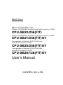
Micro Controller Unit
Windows XP Embedded Preinstall, model built in memory 256MB
CPU-SB22/256(FIT)
Windows XP Embedded Preinstall, model built in memory 256MB
CPU-SB21/256(FIT)GY
Corresponding to Windows XP/PC-DOS/Linux,
model built in memory 256MB
CPU-SB20/256(FIT)GY
Corresponding to Windows XP/PC-DOS/Linux,
model built in memory 128MB
CPU-SB20/128(FIT)GY
User’s Manual
CONTEC CO.,LTD.
Check Your Package
Thank you for purchasing the CONTEC product.
The product consists of the items listed below.
Check, with the following list, that your package is complete.
items, contact your retailer.
If you discover damaged or missing
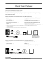
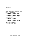
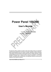
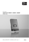
Product Configuration List [CPU-SB22/256(FIT), CPU-SB21/256(FIT)GY]
- Module …1
- CompactFlash with Windows XP Embedded
installed *1 … 1
- First step guide …1
- Power connector ...1
- CD-ROM [F&eIT Series Setup Disk]*2 …1
- Keyboard/mouse branch cable ...1
- END USER LICENSE AGREEMENT FOR
MICROSOFT SOFTWARE
(Windows XP Embedded License Agreement) …1
- Magnet ...2
*1 :With the 1GB CompactFlash In case of the CPU-SB22/256(FIT).
With the 512MB CompactFlash In case of the
CPU-SB21/256(FIT)GY
*2 : The CD-ROM contains various software and User’s Manual (this manual)
END USER
Power connector
LICENSE
AGREEMENT
FOR
MICROSOFT
SOFTWAR
Magnet x 2
CD-ROM
[F&eIT Series Setup Disk] CompactFlash First step guide END USER LICENSE
AGREEMENT FOR
MICROSOFT SOFTWAR
(Windows XP Embedded
Keyboard/mouse branch cable
License Agreement)
CPU-SB20
Module
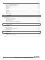
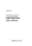
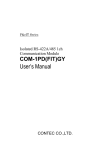
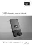
Product Configuration List [CPU-SB20/256(FIT)GY, CPU-SB20/128(FIT)GY]
- Module …1
- Keyboard/mouse branch cable ...1
- First step guide …1
- Magnet ...2
- Power connector ...1
- CD-ROM [F&eIT Series Setup Disk]*2 …1
*2 : The CD-ROM contains various software and User’s User’s Manual (this manual)
Power connector
Magnet x 2
CPU-SB20
Module
Keyboard/mouse branch cable
CD-ROM
[F&eIT Series Setup Disk] First step guide
CPU-SB22/256(FIT), CPU-SB21/256(FIT)GY, CPU-SB20/xxx(FIT)GY
i
Copyright
Copyright 2003 CONTEC CO., LTD.
ALL RIGHTS RESERVED
No part of this document may be copied or reproduced in any form by any means without prior written
consent of CONTEC CO., LTD.
CONTEC CO., LTD. makes no commitment to update or keep current the information contained in this
document. The information in this document is subject to change without notice.
All relevant issues have been considered in the preparation of this document. Should you notice an
omission or any questionable item in this document, please feel free to notify CONTEC CO., LTD.
Regardless of the foregoing statement, CONTEC assumes no responsibility for any errors that may
appear in this document or for results obtained by the user as a result of using this product.
Trademarks
F&eIT is a registered trademark of CONTEC CO., LTD. MS, Microsoft, MS-DOS and Windows are
trademarks of Microsoft Corporation. Other company and product names mentioned herein are
generally trademarks or registered trademarks of their respective owners.
ii
CPU-SB22/256(FIT), CPU-SB21/256(FIT)GY, CPU-SB20/xxx(FIT)GY
Table of Contents
Check Your Package ................................................................................................................................ i
Copyright .................................................................................................................................................ii
Trademarks ..............................................................................................................................................ii
Table of Contents ...................................................................................................................................iii
1.
Before Using the Product
1
About the Module.................................................................................................................................... 1
Features............................................................................................................................................. 1
Verified Operating Systems............................................................................................................. 1
Support Software.............................................................................................................................. 2
Customer Support.................................................................................................................................... 3
Web Site ........................................................................................................................................... 3
Limited Three-Years Warranty............................................................................................................... 3
How to Obtain Service............................................................................................................................ 3
Liability ................................................................................................................................................... 3
Safety Precautions............................................................................................................................ 4
Safety Information ........................................................................................................................... 4
Handling Precautions ....................................................................................................................... 4
Environment ..................................................................................................................................... 6
Inspection ......................................................................................................................................... 6
Storage.............................................................................................................................................. 6
Disposal ............................................................................................................................................ 6
2.
Hardware Setup
7
Getting Started......................................................................................................................................... 7
Mounting the Module.............................................................................................................................. 8
Mounting on a DIN rail.................................................................................................................. 11
Connection Method ............................................................................................................................... 15
Supplying the Power to the Controller Module ............................................................................ 15
Installation Conditions ................................................................................................................... 16
3.
Functions of the Various Components
19
Nomenclature ................................................................................................................................. 19
Keyboard/Mouse Interface ............................................................................................................ 20
Serial Port Interface ....................................................................................................................... 21
CRT Interface................................................................................................................................. 28
CompactFlash Slot ......................................................................................................................... 29
CF LED: Red.................................................................................................................................. 29
POWER LED: Green ..................................................................................................................... 29
L1: User Programable LED1 Red ................................................................................................. 29
CPU-SB22/256(FIT), CPU-SB21/256(FIT)GY, CPU-SB20/xxx(FIT)GY
iii
L2: User Programable LED2 Green ..............................................................................................29
uSW: User Programable Switch ....................................................................................................29
RESET SW .....................................................................................................................................30
USB ports........................................................................................................................................30
Ethernet ...........................................................................................................................................31
POWER...........................................................................................................................................32
LINE OUT ......................................................................................................................................32
MIC .................................................................................................................................................32
Expansion Bus ................................................................................................................................32
4.
BIOS Setup
37
BIOS Setup ............................................................................................................................................37
Launching the Setup Screen...........................................................................................................37
Keys and their functions.................................................................................................................37
Setting Item Tree ............................................................................................................................39
When Using IRQ5 on the Expansion Bus .....................................................................................40
5.
Specifications
41
Specifications.........................................................................................................................................41
System Configuration ............................................................................................................................43
Example System Configurations....................................................................................................43
External Dimensions..............................................................................................................................44
6.
Appendix
45
Watchdog Timer ....................................................................................................................................45
Setting table of a watch dog ...........................................................................................................46
Q&A .......................................................................................................................................................53
iv
CPU-SB22/256(FIT), CPU-SB21/256(FIT)GY, CPU-SB20/xxx(FIT)GY
1. Before Using the Product
1. Before Using the Product
This section explains information you need to know about this product before you use it.
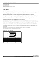
About the Module
This product is an ultra-small embedded controller that combines all the functions you need in a
compact package. The module includes an expansion bus which you can use to add functions such as
digital and analog I/O to your embedded controller by connecting other F&eIT series modules.
Alternatively, the module can be used on its own as a standard PC.
The module is ideal if you require a system with low power consumption that can fit into a small space.
*1 The "x" in a model code represents a single digit (or no digit) indicating different products. (The
same convention applies below).
Model:
CPU-SB22/256(FIT): Model with Windows XP Embedded pre-installed OS (CF:1GB)
CPU-SB21/256(FIT)GY: Model with Windows XP Embedded pre-installed OS (CF:512MB)
CPU-SB20/xxx(FIT)GY: Model which has no OS
Features
-
Fits a PC with expansion capability into a very small size (52.4mm x 64.7mm x 94mm).
The low-power 266MHz Geode SC2200 CPU can operate without a fan.
Compact flash memory can be used for diskless operation.
Equipped with AC97 compliant audio features
Incorporates an expansion bus (connectable to F&eIT series modules).
Like other F&eIT series products, the module has a 35mm DIN rail mounting mechanism as
standard. The system features a unique configuration for its connection to a module on the side in
a stacking manner, which allows you to configure the system simply and elegantly without using
backplanes and other connecting devices.
Verified Operating Systems
Operating system for which the CPU-SB20/xxx (FIT)GY (Model which has no OS) operation has been
confirmed is as follows.
- Microsoft Windows XP Professional, Embedded
- Microsoft Windows 2000 Professional
- Microsoft Windows Me
- Microsoft Windows 98 SE
- IBM PC-DOS 2000 Ver.7.0
- Linux 2.4.17Kernel
*
Verified Operating Systems: Basic OS operation and VGA and LAN driver operation has been
confirmed.
*
CONTEC does not guarantee that all OS functions will
operate correctly.
You can build a Windows XP or Windows XP 2000 SP3/SP4 environment on
the CPU-SB20/xxx(FIT)GY by installing the OS using a retail USB-based CD-ROM drive or FDD
without using the DTK-SB20(FIT). You can also install another OS such as DOS if you prepare a
retail USB CD-ROM drive supported by a startup disk for the OS.
CPU-SB22/256(FIT), CPU-SB21/256(FIT)GY, CPU-SB20/xxx(FIT)GY
1
1. Before Using the Product
Support Software
You should use CONTEC support software according to your purpose and development environment.
Driver library API-SBP(W32) (Available for downloading (free of charge) from the CONTEC web
site.)
API-SBP(W32) is the library software that provides the commands for CONTEC hardware products in
the form of Windows standard Win32 API functions (DLL).
It makes it easy to create high-speed application software taking advantage of the F&eIT module using
various programming languages that support Win32 API functions, such as Visual Basic and Visual
C++.
It can also be used by the installed diagnosis program to check hardware operations.
CONTEC provides download services (at http://www.contec.com/fit/page5.htm) to supply the updated
drivers.
For details, refer to the driver’s bundled help file or visit the CONTEC’s Web site.
< Operating environment >
OS
Windows XP, 2000, Me, 98, etc..
Adaptation language Visual C++, Visual Basic, etc..
2
CPU-SB22/256(FIT), CPU-SB21/256(FIT)GY, CPU-SB20/xxx(FIT)GY
1. Before Using the Product
Customer Support
CONTEC provides the following support services for you to use CONTEC products more efficiently
and comfortably. No driver software is provided with this module. Please download the latest
drivers from the CONTEC web site (http://www.contec.co.jp/). Documents including important notes
on the use of the module are also posted on the web site. Please visit the CONTEC web site before
using the module.
Web Site
Japanese
English
Chinese
http://www.contec.co.jp/
http://www.contec.com/
http://www.contec.com.cn/
Latest product information
CONTEC provides up-to-date information on products.
CONTEC also provides product manuals and various technical documents in the PDF.
Free download
You can download updated driver software and differential files as well as sample programs available in
several languages.
Note! For product information
Contact your retailer if you have any technical question about a CONTEC product or need its price,
delivery time, or estimate information.
Limited Three-Years Warranty
CONTEC Interface modules are warranted by CONTEC CO., LTD. to be free from defects in material
and workmanship for up to three years from the date of purchase by the original purchaser.
Repair will be free of charge only when this device is returned freight prepaid with a copy of the
original invoice and a Return Merchandise Authorization to the distributor or the CONTEC group office,
from which it was purchased.
This warranty is not applicable for scratches or normal wear, but only for the electronic circuitry and
original modules. The warranty is not applicable if the device has been tampered with or damaged
through abuse, mistreatment, neglect, or unreasonable use, or if the original invoice is not included, in
which case repairs will be considered beyond the warranty policy.
How to Obtain Service
For replacement or repair, return the device freight prepaid, with a copy of the original invoice. Please
obtain a Return Merchandise Authorization number (RMA) from the CONTEC group office where you
purchased before returning any product.
*
No product will be accepted by CONTEC group without the RMA number.
Liability
The obligation of the warrantor is solely to repair or replace the product. In no event will the warrantor
be liable for any incidental or consequential damages due to such defect or consequences that arise from
inexperienced usage, misuse, or malfunction of this device.
CPU-SB22/256(FIT), CPU-SB21/256(FIT)GY, CPU-SB20/xxx(FIT)GY
3
1. Before Using the Product
Safety Precautions
Understand the following definitions and precautions to use the product safely.
Safety Information
This document provides safety information using the following symbols to prevent accidents resulting in
injury or death and the destruction of equipment and resources. Understand the meanings of these
labels to operate the equipment safely.
DANGER
DANGER indicates an imminently hazardous situation which, if not avoided, will
result in death or serious injury.
WARNING
WARNING indicates a potentially hazardous situation which, if not avoided, could
result in death or serious injury.
CAUTION
CAUTION indicates a potentially hazardous situation which, if not avoided, may
result in minor or moderate injury or in property damage.
Handling Precautions
DANGER
Please do not use the product in environments subject to flammable and corrosive gas.
it can bring on exploding, fire, electric shock and trouble.
Otherwise,
CAUTION
-
Do not use or store the equipment in a hot or cold place, or a place that is subject to severe
temperature changes.
Examples:
- Under direct sunlight
- Near a heat source
-
Do not use or store the equipment in a place that is subject to extreme humidity or dust. It will be
extremely dangerous to use the equipment when its interior is contaminated with water or liquid, or
conducting debris. When using the equipment in an environment that is subject to water or
conducting debris, consideration should be given to the installation of a control panel with a
structure that keeps dust out.
-
Do not use or store the equipment in a place that is subject to shock or vibrations.
-
Do not use or store the product near equipment generating a strong magnetic field or radio waves.
-
Do not use or store the equipment in air with diffused chemicals or in an environment in which the
equipment can come into contact with chemicals.
-
When attaching or detaching a module or a connector, please be sure that the power cable for the
system is unplugged from the outlet.
-
Do not modify the unit. CONTEC will bear no responsibility for any problems, etc., resulting from
modifying this unit.
4
CPU-SB22/256(FIT), CPU-SB21/256(FIT)GY, CPU-SB20/xxx(FIT)GY
1. Before Using the Product
-
If you notice any malfunction or abnormal conditions (such or a strange odor or overheating),
please unplug the power cord and consult either CONTEC's Information Center or the dealer from
whom the system was purchased.
-
To connect with peripherals, use a grounded, shielded cable.
-
To clean the CPU-SBxx(FIT)GY, gently wipe it with a soft cloth soaked with water or a neutral
detergent. Do not use benzene, a thinner, or other volatile solvents as they can cause the coating to
discolor or peel off.
-
Life of the components
Battery ... A primary lithium battery is used to back up the internal clock/calendar and the CMOS
RAM. When the power is not drawn and the battery is stored at 25°C, it will last over
6 years.
* The supply items can be replaced in the same manner as the repair of the system (chargeable).
FCC PART 15 Class A Notice
NOTE
This equipment has been tested and found to comply with the limits for a Class A digital
device, pursuant to part 15 of the FCC Rules. These limits are designed to provide reasonable
protection against harmful interference when the equipment is operated in commercial
environment.
This equipment generates, uses, and can radiate radio frequency energy and, if not installed
and used in accordance with the instruction manual, may cause harmful interference to radio
communications. Operation of this equipment in a residential area is likely to cause harmful
interference at his own expense.
WARNING TO USER
Change or modifications not expressly approved the manufacturer can void the user's
authority to operate this equipment.
CPU-SB22/256(FIT), CPU-SB21/256(FIT)GY, CPU-SB20/xxx(FIT)GY
5
1. Before Using the Product
Environment
Use this product in the following environment.
may overheat, malfunction, or cause a failure.
If used in an unauthorized environment, the module
Operating temperature
0 - 50ºC
Operating humidity
10 - 90%RH (No condensation)
Corrosive gases
None
Floating dust particles
Not to be excessive
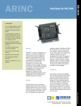
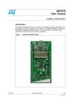
Inspection
Inspect the product periodically as follows to use it safely.
*The ventilation slits are not covered,
and neither dust nor alien substance is attached to the ventilation slits
CPU-SB20
*Make sure that the connectors
on the module side are correctly
connected with the cables
Storage
When storing this product, keep it in its original packing form.
(1) Put the module in the storage bag.
(2) Wrap it in the packing material, then put it in the box.
(3) Store the package at room temperature at a place free from direct sunlight, moisture, shock,
vibration, magnetism, and static electricity.
Disposal
When disposing of the product, follow the disposal procedures stipulated under the relevant laws and
municipal ordinances.
6
CPU-SB22/256(FIT), CPU-SB21/256(FIT)GY, CPU-SB20/xxx(FIT)GY
2. Hardware Setup
2. Hardware Setup
Getting Started
Follow the following procedures to set up the CPU-SB2x/xxx(FIT)xx:
STEP1
Connecting the F&eIT series module
By referring to this chapter connects the F&eIT series module to the
CPU-SB2x/xxx(FIT)xx. When using the CPU-SB2x/xxx(FIT)xx on a standalone basis, go
to STEP2.
STEP2
Connecting the cables
Connect the cables for the CRT and other external devices to the CPU-SB2x/xxx(FIT)xx.
STEP3
Turning on the power
After re-checking that STEPS 1 to 2 have been correctly performed, turn on the power. If
something goes wrong after the power is turned on, immediately turn off the power and
make sure that the system is correctly set up.
CPU-SB22/256(FIT), CPU-SB21/256(FIT)GY, CPU-SB20/xxx(FIT)GY
7
2. Hardware Setup
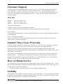
Mounting the Module
Stack Connection Locking Devices
The module contains connecting locking devices (
mark, two units at the top and bottom).
Locking device
8
CPU-SB22/256(FIT), CPU-SB21/256(FIT)GY, CPU-SB20/xxx(FIT)GY
2. Hardware Setup
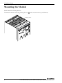
How the stack connection locking device works
-
Locking
Push the pawl of the locking device with a tool that has a slender tip downward from above to open
the spring for the locking device
(the groove moves toward you).
Locking device
-
Unlocking
Push the groove of the locking device with a tool that has a slender tip in the direction of the arrow
until the device is locked.
Locking device
CPU-SB22/256(FIT), CPU-SB21/256(FIT)GY, CPU-SB20/xxx(FIT)GY
9
2. Hardware Setup
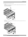
Connecting the module
Inserting the stack hook by aligning it with the hook insertion inlet for the other device automatically
locks the module. (If a stack connector protective cover is attached, the connection operation should
be performed after the cover is removed.)
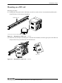
Removing the module
Unlock the locking device at the top and the bottom.
10
Remove the connected module from the hook.
CPU-SB22/256(FIT), CPU-SB21/256(FIT)GY, CPU-SB20/xxx(FIT)GY
2. Hardware Setup
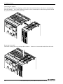
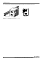
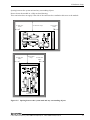
Mounting on a DIN rail
Mounting procedure
(1) Pushing the fixing hook with a flat-blade screwdriver renders it into a lock-enabled condition (this
should be done on all connected modules).
35mm DIN rail
Press here to life the fixing hook.
Figure 2.1. Mounting on a DIN rail
<1/3>
(2) Hook the unit (an object consisting of a controller and a module) from the upper part of the DIN rail,
and press the lower part of the unit onto the DIN rail.
Side view
Figure 2.1. Mounting on a DIN rail
<2/3>
CPU-SB22/256(FIT), CPU-SB21/256(FIT)GY, CPU-SB20/xxx(FIT)GY
11
2. Hardware Setup
(3) The fixing hook is automatically locked, and the module can be mounted in one-touch.
Side view
Fixing hook
Figure 2.1. Mounting on a DIN rail
12
<3/3>
CPU-SB22/256(FIT), CPU-SB21/256(FIT)GY, CPU-SB20/xxx(FIT)GY
2. Hardware Setup
Removal procedure
(1) Lower the fixing hook for the unit to unlock it.
connected modules.)
(This operation should be performed on all
35mm DIN rail
Figure 2.2. Removing the module from the DIN rail
<1/3>
(2) With the fixing hook unlocked, pull the lower part of the unit toward you.
Side view
Figure 2.2. Removing the module from the DIN rail
<2/3>
CPU-SB22/256(FIT), CPU-SB21/256(FIT)GY, CPU-SB20/xxx(FIT)GY
13
2. Hardware Setup
(3) By lifting the unit, you can easily remove it from the DIN rail.
Side view
Figure 2.2. Removing the module from the DIN rail
<3/3>
CAUTION
Any operation involving the disconnection of modules in a unit
(in which multiple modules are connected) that is attached to a DIN rail should be performed after
the unit is removed from the DIN rail.
14
CPU-SB22/256(FIT), CPU-SB21/256(FIT)GY, CPU-SB20/xxx(FIT)GY
2. Hardware Setup
Connection Method
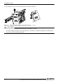
Supplying the Power to the Controller Module
(1) The DC-DC power supply unit and the controller module can be cable-connected using the
detachable connector that is provided on either the unit face or module face . Use a cable no longer
than 40cm (AWG24 to 16). (No longer than 15cm for AWG28 and no longer than 30cm for
AWG26). (compatible cables: AWG 28 to 16). When connecting, remove approximately 7mm of
insulation from the end of the cable
Apply a conductor tightening torque of 0.22 to 0.25 Nm.
CAUTION
The power supply for the device modules connected to the expansion bus is supplied via the
stack connector.
Cable connection
POWER
Vo+
5VDC VoFG
10*30VDC
Vo+
VoFG
POW-DD10
CPU-SB20
Figure 2.3. Connecting the controller module to the DC-DC power supply unit
CPU-SB22/256(FIT), CPU-SB21/256(FIT)GY, CPU-SB20/xxx(FIT)GY
15
2. Hardware Setup
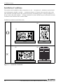
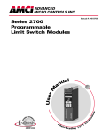
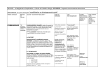
Installation Conditions
The system can be installed in either orientation (1) or (2). Orientation (3), which does not lend itself
to heat dissipation, should be avoided. A minimum clearance of 50 mm at the top and 10 mm on the
sides should be provided between the system unit and any surrounding objects. If using orientation (1),
do not connect any other modules. If using orientation (2), other modules may be connected but ensure
a clearance on the bottom side of at least 20mm.
Installation orientation (stand-alone unit)
(2)
(1)
CPU-SB20
O
CPU-SB20
Wall
Wall
(4)
(3)
CPU-SB20
×
Wall
Wall
Figure 2.4. Installation orientation
16
CPU-SB22/256(FIT), CPU-SB21/256(FIT)GY, CPU-SB20/xxx(FIT)GY
2. Hardware Setup
Spacing between the system unit and any surrounding objects
Do not locate the module in a fully enclosed housing.
This restriction does not apply if the side of the enclosure has ventilation slits next to the module.
10 mm min.
(side)
50 mm min.(top)
10 mm min.
(side)
CPU-SB20
10 mm min.
(side)
50 mm min.
(top)
10 mm min.
(side)
CPU-SB20
Figure 2.5. Spacing between the system unit and any surrounding objects
CPU-SB22/256(FIT), CPU-SB21/256(FIT)GY, CPU-SB20/xxx(FIT)GY
17
2. Hardware Setup
18
CPU-SB22/256(FIT), CPU-SB21/256(FIT)GY, CPU-SB20/xxx(FIT)GY
3. Functions of the Various Components
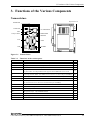
3. Functions of the Various Components
Nomenclature
Expansion bus
RESET SW
LINE OUT
10/100BASE-TX
MIC
KEYBOARD
/MOUSE
CompactFlash
VGA
COM
USB
POWER
CPU-SB20
Figure 3.1. Nomenclature
Table 3.1.
Functions of the various parts
Name
Function
Keyboard/MOUSE Keyboard/mouse connector
Page
(MINI-DIN 6-pin)
COM
Serial port connector
VGA
CRT connector
CompactFlash
Compact FLASH insertion connector
20
(D-SUB 9-pin)
21
(HD-SUB 15-pin)
28
(TYPE 1 True IDE)
Any microdrive or CompactFlash that supports True IDE mode can be used.
29
L1
User Programable LED1 : The LED can be turned on or off via IO port 8800H[0].
29
L2
User Programable LED2 : The LED can be turned on or off via IO port 8801H[0].
29
CF
Compact FLASH access verification LED
29
uSW
User Programable Switch
The switch state (on or off) can be read from IO port 8802H[0].
29
RESET SW
Resets the CPU.
30
USB
USB connector (Type A)
30
LINE OUT
Line out
32
MIC
Microphone input
10/100BASE-TX
RJ-45 connector
Power
Power supply connector
(MC1,5/3-G-3,5 PHOENIX CONTACT)
32
Expansion bus
F&eIT series connector
(0.6mm pitch, 80-pin (FX-8C series,
32
(φ3.5 PHONE JACK)
(φ3.5 PHONE JACK)
32
31
CPU-SB22/256(FIT), CPU-SB21/256(FIT)GY, CPU-SB20/xxx(FIT)GY
HIROSE))
19
3. Functions of the Various Components
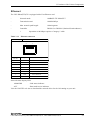
Keyboard/Mouse Interface
The system is equipped with a keyboard/mouse connector.
KEY/MOUSE (MINI-DIN 6P).
The name of the connector is
The keyboard and the mouse should be connected using a supplied branch cable. When the connector
is inserted in the orientation indicated in the table below, the right cable is for the keyboard, and the left
cable for the mouse.
If not using the branch cable, the interface can be used as a dedicated keyboard connector.
interface is disabled if a USB keyboard or mouse is used.
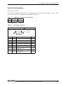
Table 3.2.
Keyboard/mouse connector
Connector type
TCS7910-16-201 (Hoshiden) or equivalent
6
5
4
3
2
20
This
1
Pin No.
Signal
Pin No.
Signal
1
+KBD DATA
5
+KBD CLK
2
+MOUSE DATA
6
+MOUSE CLK
3
GND
SHIELD
GND
4
+5.0V DC
---
CPU-SB22/256(FIT), CPU-SB21/256(FIT)GY, CPU-SB20/xxx(FIT)GY
3. Functions of the Various Components
Serial Port Interface
RS-232C port (COM)
The system is equipped with one RS-232C-compliant serial port connector (serial port A: COM).
port can be set by means of BIOS setup procedures (Chapter 4).
Table 3.3.
SERIAL1 I/O address and interrupt
COM
I/O address
Interrupt
1
3F8h-3FFh
IRQ 4
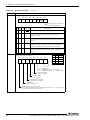
Table 3.4.
This
Serial port connector
Connector used on the system unit
1
D-SUB 9 core (male)
5
No.4-40UNC
inch screw
6
9
Pin No.
Signal
1
CD
Carrier detect
2
RD
Received data
3
TD
Transmitted data
Output
Output
Meaning
Direction
Input
Input
4
DTR
Data terminal ready
5
GND
Signal ground
-----
6
DSR
Dataset ready
Input
7
RTS
Request to send
8
CTS
Clear to send
Input
9
RI
Ring indicator
Input
Output
CPU-SB22/256(FIT), CPU-SB21/256(FIT)GY, CPU-SB20/xxx(FIT)GY
21
3. Functions of the Various Components
I/O addresses and commands
The following table shows COM1 addresses and commands:
Table 3.5.
I/O addresses
I/O address
DLAB
Read/Write
03F8h
0
W
Transmitter holding register
Register
THR
R
Receive buffer register
RBR
1
W
Divisor latch register (LSB)
DLL
03F9h
1
W
Divisor latch register (MSB)
DLM
0
W
Interrupt enable register
IER
03FAh
X
R
Interrupt ID register
IIR
03FBh
X
W
Line control register
LCR
MCR
03FCh
X
W
Modem control register
03FDh
X
R
Line status register
LSR
03FEh
X
R
Modem status register
MSR
03FFh
X
R/W
Scratch register
SCR
DLAB (Divisor Latch Access Bit) : value of bit 7 of line control register
22
CPU-SB22/256(FIT), CPU-SB21/256(FIT)GY, CPU-SB20/xxx(FIT)GY
3. Functions of the Various Components
Table 3.6.
Register functions
<1/4>
I/O address
03F8h
Description
THR: Transmitter Holding Register [DLAB=0]
D7 D6 D5 D4 D3
D2
D1
D0
bit0
LSB
bit7
MSB
Transmission data write-only register
03F8h
RBR: Reciever Buffer Register [DLAB=O]
D7 D6 D5 D4 D3
D2
D1
D0
bit0
LSB
bit7
MSB
Received data read-only register
03F8h
DLL: Divisor Latch (LSB) [DLAB=1]
D7 D6 D5 D4 D3
D2
D1
D0
bit0
LSB
bit7
MSB
Baud rate-setting register (LSB)
03F9h
DLH: Divisor Latch (MSB) [DLAB=1]
D7 D6 D5 D4 D3
D2
D1
D0
bit0
LSB
bit7
MSB
Baud rate-setting register (MSB)
03F9h
IER: Interrupt Enable Register [DLAB=0]
D7 D6 D5 D4 D3
D2
D1
0
0
0
0
EMS
D0
ELSI ETHREI ERDAI
Received data
Interrupt enabled
Received data register empty
Interrupt enabled
Receiver line status
Interrupt enabled
Modem status interrupt enabled
[Always used at 0.]
1: Interrupt enabled
0: Interrupt disabled
CPU-SB22/256(FIT), CPU-SB21/256(FIT)GY, CPU-SB20/xxx(FIT)GY
23
3. Functions of the Various Components
Table 3.6.
Register functions
<2/4>
I/O address
03FAh
Description
IIR : Interrupt Identification Register
D7
D6
D5
D4
D3
D2
0
0
0
0
D1
D0
0
Interrupt contents
bit2 bit1 bit0 Priority
03FBh
1: Interrupt not generated
0: Interrupt generated
Description
No interrupts generated
0
0
1
1
1
0
1
0
0
2
Interrupt generated when the receive buffer register
is ready. Interrupt cleared when the receive buffer is
read.
0
1
0
3
Interrupt generated when the transmitter holding
register is empty. Interrupt cleared when the IIR is
read or transmission data is written to the THR.
0
0
0
4 (low)
1 (high) Interrupt generated on overrun, parity, framing error,
or break. Interrupt cleared when the line status
register is read.
Modem status interrupts generated.(CTS, DSR, RI, CD)
Interrupt cleared when the modem status register is
read.
LCR : Line Control Register
D7
D6
D5
D4
D1 D0 Bit table
D3
D2
D1
D0
0
0
5
0
1
6
1
0
7
1
1
8
0 : 1 STOP bit
1 : 1.5 STOP bits for 5-bit length;
2 STOP bits for 6-, 7-, or 8-bit length
0 : Parity disabled
1 : Parity enabled
0 : Odd parity
1 : Even parity
0 : Stick parity disabled
1 : Stick parity enabled
0 : Break off
1 : Break signal sent
DLAB (divisor latch access bit)
For accessing the divisor latch register, set this bit to 1. For accessing
any other registers, set this bit to 0.
24
CPU-SB22/256(FIT), CPU-SB21/256(FIT)GY, CPU-SB20/xxx(FIT)GY
3. Functions of the Various Components
Table 3.6.
Register functions
<3/4>
I/O address
03FCh
Description
MCR: Modem Control Register
D7
D6
D5
D4
D3
0
0
0
Loop IRQ
D2
X
D1
D0
RTS DTR
DTR 0 : Inactive
**[HIGH]
1 : Active
** [LOW]
RTS 0 : Inactive
* [HIGH]
1 : Active
** [LOW]
Interrupt control bit
0 : Disabled
1 : Enabled
Diagnostic local loop-back test
0 : Disabled
1 : Enabled
03FDh
LSR: Line Status Register
D7
0
D6
D5
TEMT THRE
D4
D3
D2
D1
D0
BI
FE
PE
OE
DR
Data ready
('1' means data received)
Overrun error
('1' means an error detected)
Parity error ('1' means an error detected)
Framing error ('1' means an error detected)
Break interrupt ('1' means break detected)
Transmitter holding register empty
('1' means transmitter buffer empty)
Transmitter empty
('1' is set when both the transmitter holding register and the
transmitter shift register are empty)
CPU-SB22/256(FIT), CPU-SB21/256(FIT)GY, CPU-SB20/xxx(FIT)GY
25
3. Functions of the Various Components
Table 3.6.
Register functions
<4/4>
I/O address
03FEh
Description
MSR : Modem Status Register
D7 D6 D5
D4 D3
DCD
RI
D2
D1
D0
DSR CTS DDCD TERI DDSR DCTS
Delta CTS
Delta DSR
Trailing edge RI
Delta data carrier detect
CTS
DSR
Because these
status bits are
not used in the
RS-485, the
data has no
meaning.
RI
DCD
03FFh
26
SCR : Scratchpad Register
This is an 8-bit data-saving register that is user-accessible for read and
write operations.
CPU-SB22/256(FIT), CPU-SB21/256(FIT)GY, CPU-SB20/xxx(FIT)GY
3. Functions of the Various Components
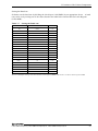
Setting the Baud rate
Software sets the baud rate by dividing the clock input (1.8432MHz) by an appropriate factor. A baud
rate can be set by writing one of the values listed in the table below into the Divisor Latch Register
(LSB, MSB):
Table 3.7.
Setting the Baud rate
Baud rate to be set
et in divisor register
Error (%)
50
2304
0.16
75
1536
0.16
110
1047
0.19
134 .5
857
0.10
150
768
0.16
300
384
0.16
600
192
0.16
1200
96
0.16
1800
64
0.16
2000
58
0.53
2400
48
0.16
3600
32
0.16
4800
24
0.16
7200
16
0.16
9600
12
0.16
19200
6
0.16
28800
4
0.16
38400
3
0.16
57600
2
0.16
115200
1
0.16
Ex.: For a 9600bps setting, write 00 to divisor latch register (MSB), and 12 (dec.) to divisor latch register (LSB).
CPU-SB22/256(FIT), CPU-SB21/256(FIT)GY, CPU-SB20/xxx(FIT)GY
27
3. Functions of the Various Components
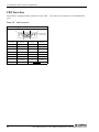
CRT Interface
The system is equipped with a connector for the CRT.
15P).
Table 3.8.
The name of the connector is VGA(HD-SUB
CRT connector
Connector type
15pin HD-SUB (MALE)
5
1
10
6
No.4-40UNC
inch screw
15
28
11
Pin No.
Signal
Pin No.
1
RED
9
Signal
N.C.
2
GREEN
10
GND
3
BLUE
11
N.C.
4
N.C.
12
N.C.
5
GND
13
HSYNC
6
GND
14
VSYNC
7
GND
15
N.C.
8
GND
CPU-SB22/256(FIT), CPU-SB21/256(FIT)GY, CPU-SB20/xxx(FIT)GY
3. Functions of the Various Components
CompactFlash Slot
A CompactFlash compliant card slot is provided. You can use TYPE I or TYPE II memory cards or
microdrives that support True IDE mode. Also, you can boot the system from the CompactFlash
(hereafter referred to as "CF") by inserting a card containing an operating system (MS-DOS, Windows,
Linux, or similar). CONTEC recommends that you use the CONTEC DTK-SB20(FIT)GY to create
the boot CF. The DTK-SB20(FIT) contains a CPU-SB20/128(FIT)GY together with a CD-ROM drive,
hard disk, and FD drive.
Remember to format the CompactFlash card in the DTK-SB20(FIT)GY before installing the OS.
For formatting the CompactFlash card, use a USB-based FDD or the DTK-SB20(FIT)GY.
The CPU-SB21/256(FIT)GY has a 512-MB CF card plugged in the slot, in which Windows XP
Embedded is already installed.
The CPU-SB22/256(FIT) has a 1-GB CF card plugged in the slot, in which Windows XP Embedded is
already installed.
Power supply for the card
Available card voltages and current values for each slot are listed below:
Table 3.9.
Power supply for the card
Voltage
Current (Max)
+5V
Not supplied
+3.3V
500mA
+12V
Not supplied
CF LED: Red
Illuminates when the CompactFlash is accessed.
Note that there is some variation between the specifications of CompactFlash cards. If you use a card
with different specifications, the LED may not illuminate or may remain permanently illuminated.
POWER LED: Green
Illuminates when the power is turned on.
L1: User Programable LED1 Red
Writing "1" to bit 0 of IO port 8800H illuminates the L1 LED (red).
permitted.
Reading the IO port state is also
L2: User Programable LED2 Green
Writing "1" to bit 0 of IO port 8801H illuminates the L2 LED (green).
permitted.
Reading the IO port state is also
uSW: User Programable Switch
Reading bit 0 of IO port 8802H indicates the switch state. A value of "1" indicates the switch is
pressed and "0" indicates no pressed. This IO port bit is read-only.
CPU-SB22/256(FIT), CPU-SB21/256(FIT)GY, CPU-SB20/xxx(FIT)GY
29
3. Functions of the Various Components
RESET SW
Pressing this button triggers a reset.
USB ports
Two OHCI Ver.1.0 compliant USB interface channels are provided.
When using USB devices, please check the current consumption of the devices to ensure the capacity of
the power supply unit provided with the module is not exceeded.
The PS/2 keyboard or mouse is disabled with a keyboard or mouse connected to the USB port.
Although the module supports the use of a USB floppy disk drive (hereafter referred to as "FDD"), this
cannot be used to boot from an MS-DOS, PC-DOS, or Windows Me boot disk. Booting from a
Windows 95 or 98 boot disk or from a Windows 2000 or XP setup disk is supported.
Similarly, booting from a USB CD-ROM drive is not supported.
To install an OS from the USB CD-ROM drive, boot from the USB FDD and install the driver for the
USB CD-ROM drive first. At this time, prepare a startup disk for Windows XP or Windows 2000 SP3
or later as it contains the USB CD-ROM driver, so that you can use the USB CD-ROM drive after
booting from the startup disk. For any other OS, prepare a USB CD-ROM drive with a DOS driver
provided and copy the DOS driver to a Windows 95/98 startup disk, so that the USB CD-ROM drive
can be used.
For details on how to install the OS, visit to the CONTEC web site to download
the “CPU-SBxx(FIT)GY OS installation procedure”.
Table 3.10.
Pin No.
30
USB connector
B1
B4
A1
A4
Signal
Pin No.
Signal
A1
USB0 Vcc
B1
USB1 Vcc
A2
USB0 -Data
B2
USB1 -Data
A3
USB0 +Data
B3
USB1 +Data
A4
USB0 GND
B4
USB1 GND
CPU-SB22/256(FIT), CPU-SB21/256(FIT)GY, CPU-SB20/xxx(FIT)GY
3. Functions of the Various Components
Ethernet
The CPU-SBxx(FIT)GY is equipped with a Fast-Ethernet card.
-
Network mode:
100BASE-TX/10BASE-T
-
Transmission rate*
100M/10M bps
-
Max. network path length:
100m/segment
-
Controller
DP83815 or DP83816 (National Semiconductor)
*
Table 3.11.
Operation at 100 Mbps requires a Category 5 cable.
Ethernet connector
Connector type
RJ-45
8
1
Pin No.
Signal
Meamimg
1
TD+
Transmitted data (+)
2
TD-
Transmitted data (-)
3
RD+
Received data (+)
4
N.C.
Not connected
5
N.C.
Not connected
6
RD-
Received data (+)
7
N.C.
Not connected
8
N.C.
Not connected
Network status display LED:
100MLINK
: Link status indicator
ACT
: Data send/receive indicator
Visit the CONTEC web site to download the network driver for the OS running on your unit.
CPU-SB22/256(FIT), CPU-SB21/256(FIT)GY, CPU-SB20/xxx(FIT)GY
31
3. Functions of the Various Components
POWER
This is a power supply connector
- Power supply:
5.0V±5%
Table 3.12.
Power supply connector
Connector type
MC1,5/3-G-3,5(PHOENIX CONTACT)
FG
Vi-
5VDC
Vi+
Pin No.
Signal name
Meaning
1
FG
Frame ground
2
Vi-
Power supply (GND)
3
Vi+
Power supply (5V)
Applicable plug (provided with module): MC1,5/3-ST-3,5(Made by PHOENIX CONTACT) (For
AWG28 - 16 cable)
The length of cable from the external power supply to the above connector must be no more than 40cm
for AWG24 - 16 cable, no more than 15cm for AWG28, and no more than 30cm for AWG26.
When connecting, remove approximately 7mm of insulation from the end of the cable. Apply a
conductor tightening torque of 0.22 - 0.25 Nm.
LINE OUT
The audio line OUT output. Plug type: φ3.5 pin jack
Stereo. Output level 8Ω 200mW. Signal to Noise ratio 90dB.
MIC
The audio MIC Input.
Plug type: φ3.5 pin jack
Expansion Bus
This is a F&eIT series connector.
Table 3.13.
Expansion bus connector
Connector type
FX8C-80S-SV(HIROSE)
FX8C-80S-SV
1
A1
Available connector:
32
B1
FX8C-80P-SV (HIROSE)
CPU-SB22/256(FIT), CPU-SB21/256(FIT)GY, CPU-SB20/xxx(FIT)GY
3. Functions of the Various Components
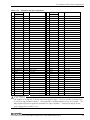
Table 3.14.
No.
Expansion bus pin assignments
Signal
Dir
Description
No.
Signal
x86
Dir
Description
x86
A01 FG
Frame ground
B01 FG
Frame ground
A02 N.C.
Not connected
B02 N.C.
Not connected
A03 SA15
OUT
Address bus 15
B03 SA14
OUT
Address bus 14
A04 SA13
OUT
Address bus 13
B04 SA12
OUT
Address bus 12
A05 SA11
OUT
Address bus 11
B05 SA10
OUT
Address bus 10
A06 SA09
OUT
Address bus 09
B06 SA08
OUT
Address bus 08
A07 SA07
OUT
Address bus 07
B07 SA06
OUT
Address bus 06
A08 SA05
OUT
Address bus 05
B08 SA04
OUT
Address bus 04
A09 SA03
OUT
Address bus 03
B09 SA02
OUT
Address bus 02
A10 SA01
OUT
Address bus 01
B10 SA00
OUT
Reserved
B11 RESERVED
A11 RESERVED
A12 RESERVED
Address bus 00
Reserved
Reserved
B12 RST_x86#
IN
CPU reset signal
A13 SD00
IN/OUT
Data bus 00
B13 SD01
IN/OUT
Data bus 01
A14 SD02
IN/OUT
Data bus 02
B14 SD03
IN/OUT
Data bus 03
A15 SD04
IN/OUT
Data bus 04
B15 SD05
IN/OUT
Data bus 05
A16 SD06
IN/OUT
Data bus 06
B16 SD07
IN/OUT
Data bus 07
A17 SD08
IN/OUT
Data bus 08
B17 SD09
IN/OUT
Data bus 09
A18 SD10
IN/OUT
Data bus 10
B18 SD11
IN/OUT
Data bus 11
A19 SD12
IN/OUT
Data bus 12
B19 SD13
IN/OUT
Data bus 13
A20 SD14
IN/OUT
Data bus 14
B20 SD15
IN/OUT
Data bus 15
Ground
B21 GND
A21 GND
Ground
A22 AEN
OUT
Address enable signal
B22 IOCHCK#
IN
NMI signal
A23 IOR#
OUT
Read signal
B23 IRQ7
IN
Interrupt signal
A24 IOW#
OUT
Write signal
B24 IRQ5
IN
Interrupt signal
B26 IO_RST#
OUT
Reset signal
B27 CPUSEN
OUT
CPU ID
A25 GND
A26 CLK8MHz
Ground
OUT
Bus clock
IN/OUT
Wait signal
A27 GND
A28 IOCHRDY#
Ground
A29 GND
Ground
A30 RESETDRV
A31 IRQ9
IN
B25 GND
Ground
B28 GND
Ground
B29 GND
Ground
ISA RESETDRV signal
B30 RESERVED
Reserved
Reserved
Interrupt signal
B31 RESERVED
Reserved
B32 RESERVED
ISA SBHE signal
B33 IOCS16#
A34 RESERVED
Reserved
B34 RESERVED
Reserved
A35 RESERVED
Reserved
B35 RESERVED
Reserved
A36 RESERVED
Reserved
B36 RESERVED
Reserved
A37 VCC
+5.0V power supply
B37 VCC
+5.0V power supply
A38 VCC
+5.0V power supply
B38 VCC
+5.0V power supply
A39 VCC
+5.0V power supply
B39 VCC
+5.0V power supply
A40 VCC
+5.0V power supply
B40 VCC
+5.0V power supply
A32 RESERVED
A33 SBHE
IN/OUT
Reserved
IN
ISA IOCS16 signal
CAUTION
The symbol "#" at the end of an item represents negative logic. In an I/O module, normally a pin
is reset by using pin B26 IO_RST#. The signal B27 CPUSEN indicates a Low level output. The
IRQx signal represents a signal for which the rise edge is enabled. Total power ratings for the
power supply pins: 5.0VDC, 3.0A.
CPU-SB22/256(FIT), CPU-SB21/256(FIT)GY, CPU-SB20/xxx(FIT)GY
33
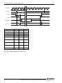
3. Functions of the Various Components
CLK8MHz
SA15-SA0
tSA2
AEN
tIOW2
tAEN1
IOW#
tIOW1
tIOW
IOCHRDY#
tRDY1
tRDY
SD7-SD0
tWSD2
tWSD1
[ns]
Item
Address delay time
Code
Min.
Max.
-
tSA2
0
AEN delay time 1
tAEN2
30
-
IOW# delay time 2
tIOW2
100
-
IOW# delay time 1
tIOW1
100
-
IOW# pulse width
tIOW
16bit-225
8bit-520
-
IOCHRDY# delay
time
tRDY1
-
16bit-75
8bit-360
IOCHRDY# pulse
width
tRDY
125
15600
Data delay time
tWSD1
16bit-123
8bit-140
-
Data hold time
tWSD2
45
-
Figure 3.2. Expansion bus I/O write cycle
34
CPU-SB22/256(FIT), CPU-SB21/256(FIT)GY, CPU-SB20/xxx(FIT)GY
3. Functions of the Various Components
CLK8MHz
SA15-SA0
tSA2
AEN
tIOR2
IOR#
tAEN1
tIOR1
tIOR
IOCHRDY#
tRDY1
tRDY
SD7-SD0
tRSD1
tRSD2
[ns]
Item
Address delay time
Code
Min.
Max.
-
tSA2
0
AEN delay time 1
tAEN1
30
-
IOW# delay time 2
tIOR2
100
-
IOW# delay time 1
tIOR1
100
-
IOW# pulse width
tIOR
16bit-160
8bit-520
-
tRDY1
-
16bit-75
8bit-360
IOCHRDY# pulse width
tRDY
125
15600
Data setup time
tRSD1
24
-
Data hold time
tRSD2
45
-
IOCHRDY# delay time
Figure 3.3. Expansion bus I/O read cycle
IRQ
tIRQ1
Item
tIRQ2
Code
Min.
Recovery time
tIRQ2
125
Max.
-
Data hold time
tIRQ2
*1
*1
*1 Hi level until the interrupt is complete
Figure 3.4. Expansion bus interrupt cycle
CPU-SB22/256(FIT), CPU-SB21/256(FIT)GY, CPU-SB20/xxx(FIT)GY
35
3. Functions of the Various Components
36
CPU-SB22/256(FIT), CPU-SB21/256(FIT)GY, CPU-SB20/xxx(FIT)GY
4. BIOS Setup
4. BIOS Setup
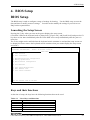
BIOS Setup
The BIOS setup is used to configure a range of settings for booting. Use the BIOS setup to reset the
date and time or modify resource settings. You also need to modify the settings if you wish to use
IRQ5 on the expansion bus.
Launching the Setup Screen
Pressing the F1 key when you turn on the power displays the setup screen.
(Check the LEDs on the keyboard such as [Num-Lock], [Caps Lock], and [Scroll Lock] and press the F1
key three or four times immediately after the LEDs blink twice except immediately after the power is
turned on.
The F1 key might not be notified when the keyboard switch container is used and the setup screen not
be displayed. Please remove the keyboard switch container when you cannot display the setup screen
and work.)
Platform: CPU-SB20(FIT)
National Semiconductor XpressROM Setup
Built: 11/20/2002 16:20:46
Main Menu
A. Time 20:28:30
B. Date 11/21/2002
C. Motherboard Device Configuration
D. Memory Optimization
H. Miscellaneous Configuration
L. Load Defaults
S. Save Values Without Exit
Q. Exit Without Save
X. Save values and Exit
Set the current time in the RTC
Keys and their functions
At the time of setup, the keys have the following functions that can be used:
Table 4.1.
List of keys and functions
Key
↑, ↓
Function
Moves settings.
+,-
Changes the setting value.
<Enter>
Opens a sub-menu.
<Esc>
Goes back to parent screen.
CPU-SB22/256(FIT), CPU-SB21/256(FIT)GY, CPU-SB20/xxx(FIT)GY
37
4. BIOS Setup
38
CPU-SB22/256(FIT), CPU-SB21/256(FIT)GY, CPU-SB20/xxx(FIT)GY
4. BIOS Setup
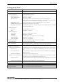
Setting Item Tree
Time
Sets the time
Date
Sets the date
Motherboard Device Configration
Drive Configration
Specifies IDE drive settings.
IDE BIOS Support
Always set to "Enable".
Chipset IDE Channel
Always set to "Both".
PIO mode setup
Sets the data transfer speed in PIO mode for the CompactFlash slot.
Modes 0 to 4 specify increasingly faster speeds. Check the specifications of the
CompactFlash you are using and set an appropriate value.
DMA/UDMA support
As this module does not support IDE DMA, always set to "Disable".
CD-ROM Boot Configration This setting is not used on this module.
Boot Order Configration
Sets the priority order for booting.
to the CompactFlash slot.
On this system, "Hard Drive #1" corresponds
LPC Card Devices
Serial Port
Sets the COM port resources.
FDC
Always set to "Disable".
Audio Configration
Audio Enable
Enables or disables audio support.
Audio Base
Always set to "0x220".
Audio IRQ
If audio support is enabled, always set this to IRQ5.
Audio 8bit DMA
Always set to "Channel 1".
Audio 16bit DMA
Always set to "Channel 5".
Video Configration
Sets the video RAM settings.
PCI Configration
Sets the PCI interrupt routing.
Memory Optimization
Always set to "4MB".
Sets the memory timing. As setting an incorrect value may prevent the system
from booting, ensure this is always left at the factory default setting.
Miscellaneous Configration
Splash Screen Configration
The Splash Screen is the CONTEC logo displayed when the power is turned on.
Splash Screen
Specifies whether or not to display the CONTEC logo when the power is turned
on.
Clear Splash Screen
If set to "Enable", pressing a keyboard key while the CONTEC logo is displayed
clears the screen.
Splash Screen Timeout
Summary Screen Configration
Specifies how long to display the logo.
The Summary Screen is displayed after the Splash Screen and displays system
information (memory size, IDE device information, etc.)
Summary Screen
Specifies whether or not to display system information when the power is turned
on.
Summary Screen Timeout
Specifies how long to display the system information.
Load Defaults
Restores all settings except the date and time to their factory default settings.
Save Values Without Exit
Saves the settings.
Exit Without Save
Reboots the system without saving the settings.
Save values and Exit
Saves the settings and then reboots the system.
CPU-SB22/256(FIT), CPU-SB21/256(FIT)GY, CPU-SB20/xxx(FIT)GY
39
4. BIOS Setup
When Using IRQ5 on the Expansion Bus
The audio function on the module is only able to use IRQ5. Accordingly, the default factory settings
assign IRQ5 to the audio function and using IRQ5 on the expansion bus results in a conflict.
If you want to use IRQ5 on the expansion bus, please change the following settings.
-
In the PCI Configuration, set INTC to "Disable".
-
In the Audio Configuration, set Audio IRQ to "Disable".
When COM-2(FIT)GY is used with Windows, I will recommend an enhanced mode attached CD-ROM
driver to use IRQ7 or IRQ9.
40
CPU-SB22/256(FIT), CPU-SB21/256(FIT)GY, CPU-SB20/xxx(FIT)GY
5. Specifications
5. Specifications
Specifications
Table 5.1.
Functional Specifications
Model
CPU-SB22/256(FIT)
CPU-SB21/256(FIT)GY
CPU-SB20/256(FIT)GY
CPU
Geode SC2200 266MHz
Chip Set
Built-in CPU
Memory
Video
Main Memory
CPU-SB20/128(FIT)GY
Micro-DIMM Socket x 1
Micro-DIMM Socket x 1
Standard provides 256Mbyte Micro-DIMM Standard provides 128Mbyte Micro-DIMM
BIOS ROM
128KByte E0000h to FFFFFh
Controller
Built-in CPU
Video RAM
4MByte equivalent
CRT I/F
15pin HD-SUB connector
640 x 480/800 x 600 (65,536 colors), 1024 x768 (65,536 colors),
1280 x1024 (256 colors)
Serial I/F
RS-232C (generic): 1ch, 9pin D-SUB connector
LAN I/F
Ethernet 100BASE-TX/10BASE-T RJ-45 connector
DP83815 or DP83816 (National Semiconductor)
Audio I/F
Output: Line OUT x 1(Stereo. Output level 8Ω 200mW. Signal to Noise ratio 90dB.),
USB I/F
2ch(OHCI Ver.1.0 compliant)
Input: MIC x 1(Monaural), Plug type: φ3.5 pin JACK
Keyboard I/F
PS/2 type keyboard (6 pins, MINI DIN connector)
Mouse I/F
PS/2 type mouse (6 pins, MINI DIN connector)
F&eIT I/F
F&eIT series module connectivity
(When using POW-DD10 power supply unit, the total power for externally connected
units. Should not exceed 1.5 A)
Watchdog timer function
Programmable (16666sec(Max.))
(Output to either RESET or IRQ, depending on time-up)
Compact Flash Slot
TYPE I or TYPE II x 1
The CPU-SB22/256(FIT) comes standard with a 1-GB CF card with Windows XP
Embedded installed.
The CPU-SB21/256(FIT)GY comes standard with a 512-MB CF card with Windows XP
Embedded installed.
RTC/CMOS
Life of lithium backup battery: 6 yr. minimum (25°C)
Accuracy of realtime clock: less than 3 min./month
LED display
Power, Compact Flash access, User programmable LED x 2
Manual switch input
Reset switch x 1, User programmable switch x 1
Power
supply
Input power
voltage
5VDC ±5%
Max. power
consumption
7.5W
External dimensions (mm) 52.4(W) x 64.7(D) x 94.0(H)
Weight
300g
CPU-SB22/256(FIT), CPU-SB21/256(FIT)GY, CPU-SB20/xxx(FIT)GY
41
5. Specifications
Table 5.2.
Installation environment
Parameter
Operating temperature *1
Requirement description
0 - 50°C
Storage temperature
-10 - 60°C
Operating Humidity
10 - 90%RH (No condensation)
Floating dust particles
Not to be excessive
Corrosive gases
None
Line-Noise Line-noise *2
resistance Static
electricity
resistance
Vibration
resistance
Sweep
resistance
AC line/2kV, Signal line/1kV (IEC1000-4-4Level 3, EN61000-4-4Level 3)
Contact discharge/4kV (IEC1000-4-2Level 2, EN61000-4-2Level 2)
Atmospheric discharge/8kV (IEC1000-4-2Level 3, EN61000-4-2Level 3)
10 - 57Hz/semi-amplitude 0.15mm, 57 - 150Hz/2.0G
80minutes each in X, Y, and Z directions
(JIS C0040-compliant, IEC68-2-6-compliant)
Impact resistance
15G, half-sine shock for 11ms in X, Y, and Z directions
(JIS C004-compliant, IEC68-2-27-compliant)
Grounding
Class D grounding (previous class 3 grounding)
*1
The operating temperature range changes to 5 - 60ºC if a FAN unit (FAN-FIT) is used.
*2
In POW-AD22GY use.
42
CPU-SB22/256(FIT), CPU-SB21/256(FIT)GY, CPU-SB20/xxx(FIT)GY
5. Specifications
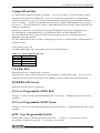
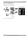
System Configuration
Example System Configurations
COM-2(FIT)GY
Network
DIO-8/8(FIT)GY
ADI12-8(FIT)GY
Mouse
Keyboard
Display
CPU-SB20
RS-232C
CF Card
Figure 5.1. System configuration diagram
CPU-SB22/256(FIT), CPU-SB21/256(FIT)GY, CPU-SB20/xxx(FIT)GY
43
5. Specifications
External Dimensions
45.0
94.0
35.0
31.5
14.0
(8.0)
(1.2)
CPU-SB20
6.0
52.4
64.7
4.0
[mm]
Figure 5.2. External Dimensions
44
CPU-SB22/256(FIT), CPU-SB21/256(FIT)GY, CPU-SB20/xxx(FIT)GY
6. Appendix
6. Appendix
Watchdog Timer
A watchdog function is provided as a failsafe mechanism for the case when the system hangs up.
When the watchdog function is triggered, it notifies the system via an interrupt or system reset.
The base IO address for the watchdog function is 9000h.
Table 6.1.
Registers
Abbreviation
Contents
Bit position
WDTO
Timeout register
Offset 00-01h
WDOVF
Overflow
Offset 04h[0]
WDPRES
32KHz clock prescaler
Offset 02h[3:0]
WD32KPD
32KHz clock enable/disable bit
Offset 02h[8]
WDTYPE1
Specifies the operation when the watchdog timer counts down to Offset 02h[5:4]
zero (for the first time).
WDTYPE2
Specifies the operation when the watchdog timer counts down to zero
(for the second time).
Notation:
Offset 02h[7:6]
Offset XXh[YY] indicates bit YY at 90XXh.
Writing a non-zero value to WDTO (timeout register (offset 00h)) enables the watchdog.
Table 6.2.
Watch dog timeout value
offset 00-01h
Bit
Contents
15:0
Watch dog timeout value
The watchdog timer is a 16-bit down counter.
The watchdog timer counts down until the count reaches zero.
The watchdog timer restarts in the following cases.
-
A non-zero value is written to WDTO.
The watchdog timer reaches zero and WDOVF is "0".
The watchdog function does not operate in the following cases.
-
When a system reset occurs
When zero is set to the WDTO register.
When the timer reaches zero and the WDOVF bit is already "1".
CPU-SB22/256(FIT), CPU-SB21/256(FIT)GY, CPU-SB20/xxx(FIT)GY
45
6. Appendix
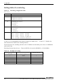
Setting table of a watch dog
Table 6.3.
Watch dog configuration table
Offset 02-03h
Bit
Contents
15:9
Reserved Read and then write back.
8
32KHz Clock enable flag
0:32KHz Clock enable flag
1:32KHz Clock disable flag
7:6
WATCHDOG Event Type 2
00:No operation
01:Interrupt
11: System reset
5:4
WATCHDOG Event Type 1
00: No operation
01: Interrupt
11: System reset
WATCHDOG Timer Prescaler
3:0
0000:1
0100:16
1000:256
1100:4096
0001:2
0101:32
1001:512
1101:8192
0010:4
0110:64
1010:1024
1110:Reserved
0011:8
0111:128
1011:2048 1111:Reserved
A value of "0" in WD32KPD (offset 02h [8]) enables the 32KHz clock.
clock and therefore disables the watchdog function.
A value of "1" disables the
The clock input to the watchdog function is the 32.768KHz clock divided by the value set in WDPRES
(offset 02h [3:0]).
Watchdog interrupt interval (sec) = Timeout (WDTO) x Prescaler (WDPRES) ÷ 32768(32KHz)
Table 6.4.
Example of a setting
WDPRES
46
Prescaler
WDTO
Timeout register
1
32768
1
1
16384
0.5
1
8192
0.25
2
32768
2
2
16384
1
2
8192
0.5
Timeout time (sec)
CPU-SB22/256(FIT), CPU-SB21/256(FIT)GY, CPU-SB20/xxx(FIT)GY
6. Appendix
When the watchdog timer reaches zero:
- If the WDOVF (offset 04h [0]) bit is "0", the interrupt or reset specified by WDTYPE1 (offset 02h
[5:4]) is generated.
-
If the WDOVF (offset 04h [0]) bit is "1", the interrupt or reset specified by WDTYPE2 (offset 02h
[7:6]) is generated and the timer is disabled.
Writing a non-zero value to the WDTO register re-enables the watchdog timer.
When watchdog event type is set to generate an interrupt, you can select the interrupt number.
Table 6.5.
Interrupt Number Selection
Offset 38h
Bit
Contents
7:4
Reserved Writing after reading
3:0
Interrupt setting table
0101:IRQ5
0111:IRQ7
1001:IRQ9
To use an interrupt, you must enable the interrupt at base address 6600h. To use IRQ5, you also need
to use the BIOS Setup to set INTC to "Disable" in the PCI Configuration. As the audio function uses
INTC-IRQ5, the IRQ5 output from the audio function and watchdog will conflict.
Setup as shown in the table below.
Table 6.6.
Interrupt Enable Settings
IRQ
Output data
IRQ5
12d2h
IRQ7
1272h
IRQ9
10f2h
You can retrieve the current watchdog status.
Table 6.7.
Watch dog status
Offset 04h
Bit
7:4
3
2
1
0
Contents
Reserved
WATCHDOG reset occurred (read-only)
Set to "1" when a reset interrupt is generated.
Cleared by a power-on reset or by writing "0" to the WDOVF bit.
WATCHDOG SMI(read-only)
Not supported
WATCHDOG Interrup (read-only)
Set to "1" when an interrupt is generated.
Cleared by a power-on reset or by writing "0" to the WDOVF bit.
WDOVF flag (read, write)
Set to "1" when an the watchdog timer counts down to zero.
Cleared by a power-on reset or by writing "1" to this bit.
CPU-SB22/256(FIT), CPU-SB21/256(FIT)GY, CPU-SB20/xxx(FIT)GY
47
6. Appendix
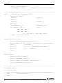
Sample program
/***************************************************************************
Sample program
***************************************************************************/
#include <stdio.h>
#include <conio.h>
#include <dos.h>
#include <bios.h>
#include <time.h>
/* ----- Constant ---------------------------------------------------------- */
#define NUM (5)
#define WDBASE 0x9000
#define
IRQ5
0
/* IRQ5 */
#define
IRQ7
1
/* IRQ7 */
#define
IRQ9
2
/* IRQ9 */
int paraIrq;
unsigned int paraPrescaler;
unsigned int paraPrescalerBit;
unsigned int paraCount;
volatile int
intcnt = 0;
/* interrupt counter */
volatile int
IrqLevel = IRQ7;
/* interrupt level */
int
OrgMasterImr, OrgSlaveImr;
/* original IMR */
unsigned char
IntVector[3] = { 0x0d, 0x0f, 0x71 };
unsigned char
PicMask[3] = { 0xdf, 0x7f, 0xfd };
/* interrupt vector */
/* mask bit */
unsigned char
IsrClear[3] = { 0x65, 0x67, 0x61 };
/* ISR clear */
/* ----- Prototype --------------------------------------------------------- */
void
main( int, char *[] );
void
ChgVect( void );
void
ResVect( void );
void
_interrupt _far inthandler( void );
void
( _interrupt _far *OrgVect)();
/* change vector */
/* restore vector */
/* interrupt handler */
/* original interrupt vector */
/* ----- change vector ------------------------------------------------------- */
void
ChgVect( void ){
OrgVect = _dos_getvect( IntVector[IrqLevel] );
_disable();
_dos_setvect( IntVector[IrqLevel], inthandler );
48
CPU-SB22/256(FIT), CPU-SB21/256(FIT)GY, CPU-SB20/xxx(FIT)GY
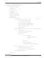
6. Appendix
if ( IrqLevel > IRQ7 ) {
/* IMR and mask clear */
outp( 0x21, ( OrgMasterImr = inp( 0x21 ) ) & 0xfb );
outp( 0xa1, ( OrgSlaveImr = inp( 0xa1 ) ) & PicMask[IrqLevel] );
outp( 0x20, 0x62 );
/* ISR clear (master) */
outp( 0xa0, IsrClear[IrqLevel] );
/* ISR clear (slave) */
} else {
/* IMR and mask clear */
outp( 0x21, ( OrgMasterImr = inp( 0x21 ) ) & PicMask[IrqLevel] );
outp( 0x20, IsrClear[IrqLevel] );
/* ISR clear */
}
_enable();
/* enable */
}
/* ----- restore vector ------------------------------------------------------ */
void
ResVect( void ){
_disable();
/* disable */
if ( IrqLevel > IRQ7 ) {
/* restore IMR */
outp( 0x21, OrgMasterImr );
outp( 0xa1, OrgSlaveImr );
} else
outp( 0x21, OrgMasterImr );
_dos_setvect( IntVector[IrqLevel], OrgVect );
/* restore orgvect */
_enable();
/* enable */
}
void wdt_init(){
unsigned int setVal;
unsigned char setValc;
setValc=inp(WDBASE+0x4);
setValc|=0x1;
/* WDOVF set 1 */
outp(WDBASE+0x4, setValc);
setValc=inp(WDBASE+0x38);
/* General Configuration Block */
setValc&=0xf0;
setValc|=(paraIrq & 0xf );
/* IRQ set */
outp(WDBASE+0x38, setValc);
setVal=inp(WDBASE+2);
/* WATCHDOG Configuration Register */
setVal&=0xfe00;
setVal|=0xc0; /* WTYPE2 0xc0:System reset 0x40:Interrupt 0x00:No action */
setVal|=0x10; /* WTYPE1 0x30:System reset 0x10:Interrupt 0x00:No action */
CPU-SB22/256(FIT), CPU-SB21/256(FIT)GY, CPU-SB20/xxx(FIT)GY
49
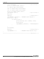
6. Appendix
setVal|=paraPrescalerBit;
outpw(WDBASE+2, setVal );
/* WATCHDOG Configuration Register */
}
/* ----- interrupt handler --------------------------------------------------- */
void
_interrupt _far inthandler( void ){
unsigned int setVal;
_enable();
/* enable */
intcnt++;
_disable();
/* disable */
wdt_init();
outpw(WDBASE+0, 0 );
/* WATCHDOG stop */
if( IrqLevel > IRQ7 ){
/* EOI */
outp( 0xa0, 0x20 );
outp( 0xa0, 0x0b );
if ( !inp( 0xa0 ) ) outp( 0x20, 0x20 );
} else
outp( 0x20, 0x20 );
}
void paraError(char *para){
printf( "Unknown parameta[%s]¥n¥n", para );
printf( "usage: itr-test [-I:irq] [-S:32kPrescaler] [-C:counter]¥n" );
printf( "
-I:5,7,9¥n" );
printf( "
-S:1,2,4,....,1024,2048,4096,8192¥n" );
printf( "
-C:1,...,65535¥n" );
exit(1);
}
void showPara(){
printf( "Program start¥n" );
printf( "IRQ=%d¥n", paraIrq );
printf( "32KHz prescale=%d¥n", paraPrescaler );
printf( "Count=%u¥n", paraCount );
}
/* ----- main --------------------------------------------------------------- */
/* parameta check */
/* -I:irq <5,7,9> */
/* -S:99 <32k Prescaler><1,2,4,8,16,32,64,128,256,512,1024,2048,4096,8192> */
/* -C:99
<counter><1-65535> */
/* default */
50
CPU-SB22/256(FIT), CPU-SB21/256(FIT)GY, CPU-SB20/xxx(FIT)GY
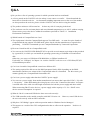
6. Appendix
/* IRQ=7, 32k Prescaler=4096, Count=16 */
void main( int argc, char *argv[] ){
unsigned int setVal;
unsigned int
i, j;
unsigned char c;
int wintcnt = 0;
paraIrq=7;
paraPrescaler=4096;
paraPrescalerBit=0xc;
paraCount=16;
for(i=1;i<argc;i++){
if( memcmp( argv[i], "-I:", 3 )==0 ){
/* set irq */
int wirq=atoi(&argv[i][3]);
if( wirq==5 )IrqLevel=IRQ5;
else if( wirq==7 )IrqLevel=IRQ7;
else if( wirq==9 )IrqLevel=IRQ9;
else paraError(argv[i]);
paraIrq=wirq;
}else if( memcmp( argv[i], "-S:", 3 )==0 ){/* set Prescaler */
int wcnt=1;
int wscale=atoi(&argv[i][3]);
paraPrescalerBit=0;
while(1){
if( wcnt==wscale ){
paraPrescaler=wcnt;
break;
}
wcnt *=2;
paraPrescalerBit++;
if( wcnt>8192 )paraError(argv[i]);
}
}else if( memcmp( argv[i], "-C:", 3 )==0 ){
paraCount=atoi(&argv[i][3]);
if( paraCount<1 )paraError(argv[i]);
}else paraError(argv[i]);
}
showPara();
CPU-SB22/256(FIT), CPU-SB21/256(FIT)GY, CPU-SB20/xxx(FIT)GY
51
6. Appendix
setVal=inpw(0x6600);
/* lpc to isa set */
printf( "in 0x6600=[%x]¥n", setVal );
if( IrqLevel==IRQ5 )setVal&=0xffdf;
else if( IrqLevel==IRQ7 )setVal&=0xff7f;
else if( IrqLevel==IRQ9 )setVal&=0xfdff;
printf( "out 0x6600=[%x]¥n", setVal );
outpw(0x6600, setVal );
/* lpc to isa set */
wdt_init();
ChgVect();
/* change vector */
outpw(WDBASE+0, paraCount ); /* WATCHDOG Timeout Register */
while( intcnt <= NUM ){
if( wintcnt!=intcnt ){
printf("interrupt count = %02d>¥n", intcnt);
wintcnt=intcnt;
outpw(WDBASE+0, paraCount ); /* Timeout Register */
}
}
printf("¥n¥n");
ResVect();
/* restore vector */
outpw(WDBASE+0, 0 );
/* WATCHDOG Timeout Register stop */
}
/* ----------------------------------------------------------- End of file --- */
52
CPU-SB22/256(FIT), CPU-SB21/256(FIT)GY, CPU-SB20/xxx(FIT)GY
6. Appendix
Q&A
Q.Do you have a list of operating systems for which operation has been confirmed?
A.A list is posted on the CONTEC web site at http://www.contec.co.com/fit/. Please download the
latest drivers from the web site. As documents including important notes on the use of the module
are also posted on the web site, please visit the CONTEC web site before using the module.
Q.The product enclosure will become hot.
Is there any risk of it warping in the heat?
A.The enclosure uses fire-resistant plastic and can withstand temperatures up to 108°C without warping.
Please ensure you use the device within the conditions specified in "Table 5.2 Installation
Environment Conditions".
Q.Which brands of CompactFlash can I use?
A.The requirement is that the CompactFlash supports True IDE mode. As some low price brands of
CompactFlash do not support True IDE mode, please check with the manufacturer or agent before
purchasing. CONTEC recommends you use CompactFlash made by Transcend Corporation.
Q.How can I install an OS in a CompactFlash card?
A.You can use the CONTEC DTK-SB20(FIT)GY to provide an environment equivalent to that provided
by a general PC, in which you can install an operating system using a CD-ROM or FD and a hard
disk.
Otherwise, you can use a USB-based CD-ROM drive or FDD to install an OS.
For details, see “USB port” in Chapter 3 or visit the CONTEC web site to see “CPU-SBxx(FIT)GY
OS installation procedure”.
Q.Can I use a bootable CompactFlash created on a different PC?
A.The setting required for disk access (the BIOS parameter block) differ depending on the BIOS
manufacturer and these are written to the CompactFlash when it is formatted. For this reason, you
cannot typically use a CompactFlash from another PC.
Q.Can I use a power supply other than the CONTEC power supply?
A.You can use a power supply from another manufacturer but ensure that it provides 5VDC+/-5% with
1.5A capacity. When determining the wiring layout, refer to the "Connection Procedure" in Chapter
2 and take note of the cable size and length restrictions for both the power supply and other cables.
When connecting F&eIT series devices, a power supply with a capacity of "1.5A + F&eIT series
device current consumption" is required.
Q.What do I do if a connected USB device does not work correctly?
A.The USB controller on the module complies with OHCI Version 1.0.
do not work correctly with an OHCI controller.
However, some USB devices
Q.Why does "PCI Bridge" appear with two question marks in Windows Device Manager?
A.This appears as a result of the CPU configuration but has no effect on the operation.
required.
CPU-SB22/256(FIT), CPU-SB21/256(FIT)GY, CPU-SB20/xxx(FIT)GY
No driver is
53
6. Appendix
Q.I have lost my PS/2 divided cable.
Can I use a standard cable purchased from a local retailer?
A.No. Most cables sold in retail stores are intended for use with notebook PCs and have different
wiring connections. Instead, please contact CONTEC. If you wish to use a keyboard only, you do
not need to use the divided cable and you can use the connector as a dedicated keyboard connector.
Q.It returns to default being cleared the content set by CMOS.
A.When power supply OFF is continuously repeated three times or more while displaying the splash
screen of the start, the setting of CMOS is cleared. This is a function (specification) that has it as an
evasion plan when the setting of CMOS is set by mistake and it falls into the state that cannot be started.
Q.The clock/calendar date was January 17, 2003 after the module was restarted?
I found the clock/calendar losing time badly. What's wrong?
A.Did you turn the power on soon after turning it off? Set the clock/calendar again, turn the power off,
wait for at least five seconds, then turn the power back on.
If the clock/calendar returns to January 17, 2003 even after you set it correctly, the on-board battery
seems to have run out. Please contact your retailer.
54
CPU-SB22/256(FIT), CPU-SB21/256(FIT)GY, CPU-SB20/xxx(FIT)GY
CPU-SB22/256(FIT)
CPU-SB21/256(FIT)GY
CPU-SB20/256(FIT)GY
CPU-SB20/128(FIT)GY
User’s Manual
CONTEC CO.,LTD.
December 2005 Edition
3-9-31, Himesato, Nishiyodogawa-ku, Osaka 555-0025, Japan
Japanese http://www.contec.co.jp/
English http://www.contec.com/
Chinese http://www.contec.com.cn/
No part of this document may be copied or reproduced in any form by any means without prior written
consent of CONTEC CO., LTD.
[12162005]
[04012003]
[12162005_rev6]
Management No. A-46-694
Parts No.
LYCC151A