1
F&eIT Series
F&eIT Series Micro Controller Unit
(2GB CF, XP Embedded Model)
CPU-SB303-FIT-3F
CPU-SB304-FIT-45F
(OS Uninstalled Model)
CPU-SB303-FIT
CPU-SB304-FIT-400
User’s Manual
CONTEC CO.,LTD.
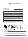
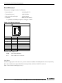
Check Your Package
Thank you for purchasing the CONTEC product.
The product consists of the items listed below.
Check, with the following list, that your package is complete.
items, contact your retailer.
If you discover damaged or missing
CPU-SB303-FIT-3F
CPU-SB304-FIT-45F
(2GB CF, XP
Embedded Model)
Pcs.
CPU-SB303-FIT
CPU-SB304-FIT-400
(OS Uninstalled
Model)
Pcs.
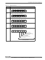
Module
1
1
First step guide
1
1
Power connector
1
1
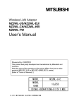
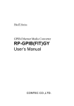
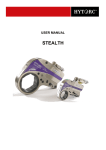
Product Configuration List
Name
F&eIT module fixing parts
2
2
1 set
1 set
CD-ROM [F&eIT Series Setup Disk] *1
1
1
Rubber feet
4
4
CF Card Retaining Bracket
1
1
IDE connector protective label
1
1
CompactFlash with Windows XP Embedded
installed *1
1
None
END USER LICENSE AGREEMENT FOR
MICROSOFT SOFTWARE(Windows XP Embedded
License Agreement)
1
None
Recovery media
1
None
Notes on Windows XP Embedded
1
None
DIN rail installation metal fittings
*1 : The CD-ROM contains various software and User’s Manual (this manual).
*2 : It is attached to CPU-SB304-FIT-45F/CPU-SB304-FIT-400.
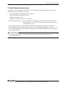
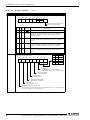
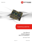
- Configuration images
x7
x4
Rubber feet
Power connector
IDE connector
protection label
x2
Module
F&eIT
module
fixing parts
DIN rail installation
metal fittings
CF card
retaining
bracket
END USER
LICENSE
AGREEMENT
FOR
MICROSOFT
SOFTWAR
CD-ROM
First step guide [F&eIT Series
Setup Disk]
Recovery CompactFlash
media
Notes on
END USER LICENSE
Windows XP
AGREEMENT FOR
Embedded
MICROSOFT SOFTWAR
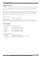
CAUTION
For operating this product, power supply (12 - 24VDC) is required separately.
For more details on the power supply, refer to “Chapter5 Specifications - About power supply”.
CPU-SB303-FIT, CPU-SB303-FIT-3F, CPU-SB304-FIT-400, CPU-SB304-FIT-45F
i
Copyright
Copyright 2007 CONTEC CO., LTD.
ALL RIGHTS RESERVED
No part of this document may be copied or reproduced in any form by any means without prior written
consent of CONTEC CO., LTD.
CONTEC CO., LTD. makes no commitment to update or keep current the information contained in this
document. The information in this document is subject to change without notice.
All relevant issues have been considered in the preparation of this document. Should you notice an
omission or any questionable item in this document, please feel free to notify CONTEC CO., LTD.
Regardless of the foregoing statement, CONTEC assumes no responsibility for any errors that may
appear in this document or for results obtained by the user as a result of using this product.
Trademarks
F&eIT is a registered trademark of CONTEC CO., LTD. MS, Microsoft and Windows are trademarks
of Microsoft Corporation. Other company and product names mentioned herein are generally
trademarks or registered trademarks of their respective owners.
ii
CPU-SB303-FIT, CPU-SB303-FIT-3F, CPU-SB304-FIT-400, CPU-SB304-FIT-45F
Table of Contents
Check Your Package ................................................................................................................................ i
Copyright.................................................................................................................................................ii
Trademarks ..............................................................................................................................................ii
Table of Contents ...................................................................................................................................iii
1.
Before Using the Product
1
About the Module ................................................................................................................................... 1
Features ............................................................................................................................................ 1
Verified Operating Systems............................................................................................................. 3
Support Software.............................................................................................................................. 4
List of Options.................................................................................................................................. 4
Customer Support.................................................................................................................................... 5
Web Site ........................................................................................................................................... 5
Limited One-Year Warranty................................................................................................................... 5
How to Obtain Service............................................................................................................................ 5
Liability ................................................................................................................................................... 5
Safety Precautions................................................................................................................................... 6
Safety Information ........................................................................................................................... 6
Handling Precautions ....................................................................................................................... 6
Environment ................................................................................................................................... 10
Inspection ....................................................................................................................................... 10
Storage............................................................................................................................................ 10
Disposal .......................................................................................................................................... 10
2.
Hardware Setup
11
Getting Started....................................................................................................................................... 11
Attaching the CF Card Retaining Bracket............................................................................................ 11
Mounting / Removing the Device Module........................................................................................... 12
Stack Connection Locking Devices .............................................................................................. 12
Mounting the Device Module........................................................................................................ 12
Removing the Module ................................................................................................................... 13
Mounting on / Removing a DIN Rail ................................................................................................... 14
Mounting on a DIN Rail Installation Metal Fittings .................................................................... 14
Mounting on a DIN rail installation metal fittings ....................................................................... 15
Removing from a DIN Rail ........................................................................................................... 16
Connection Method............................................................................................................................... 18
Supplying the Power to the Controller.......................................................................................... 18
Installation Conditions................................................................................................................... 19
CPU-SB303-FIT, CPU-SB303-FIT-3F, CPU-SB304-FIT-400, CPU-SB304-FIT-45F
iii
3.
Functions of the Various Components
23
Nomenclature.........................................................................................................................................23
Serial Port Interface........................................................................................................................25
Display Interface ............................................................................................................................31
CompactFlash Slot .........................................................................................................................32
Secondary IDE Connector..............................................................................................................33
CF LED: Red ..................................................................................................................................34
POWER LED: Green .....................................................................................................................34
L1: User Programmable LED1 Red...............................................................................................34
L2: User Programmable LED2 Green ...........................................................................................34
uSW: User Programmable Switch .................................................................................................34
RESET SW .....................................................................................................................................34
USB ports........................................................................................................................................35
Fast-Ethernet...................................................................................................................................36
Gigabit-Ethernet ....................................................................................................................................37
POWER...........................................................................................................................................39
LINE OUT ......................................................................................................................................39
MIC .................................................................................................................................................39
F&eIT I/F........................................................................................................................................40
4.
BIOS Setup
45
BIOS Setup ............................................................................................................................................45
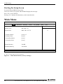
Starting the Setup Screen ...............................................................................................................46
Main Menu.............................................................................................................................................46
Keystrokes .............................................................................................................................................47
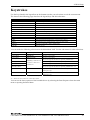
Primary/Secondary Master, Slave..................................................................................................48
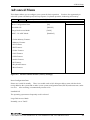
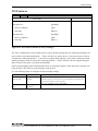
Advanced Menu.....................................................................................................................................49
Cache Memory Features.................................................................................................................50
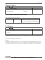
Memory Features............................................................................................................................51
PCI Features ...................................................................................................................................51
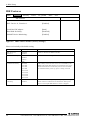
IDE Features ...................................................................................................................................52
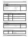
Video Features................................................................................................................................53
LAN Features .................................................................................................................................53
USB Features ..................................................................................................................................54
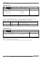
Audio Features................................................................................................................................54
I/O Features ....................................................................................................................................55
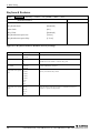
Keyboard Features..........................................................................................................................56
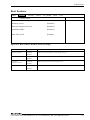
Boot Features ..................................................................................................................................57
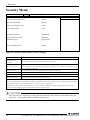
Security Menu........................................................................................................................................58
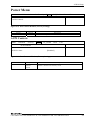
Power Menu ...........................................................................................................................................59
ACPI Controls ................................................................................................................................59
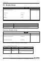
PC Health Menu ....................................................................................................................................60
Hardware Monitor Setup................................................................................................................60
iv
CPU-SB303-FIT, CPU-SB303-FIT-3F, CPU-SB304-FIT-400, CPU-SB304-FIT-45F
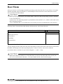
Boot Menu ............................................................................................................................................. 61
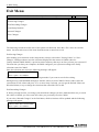
Exit Menu .............................................................................................................................................. 62
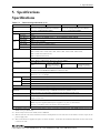
5.
Specifications
65
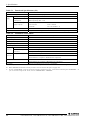
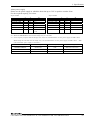
Specifications ........................................................................................................................................ 65
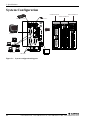
System Configuration ........................................................................................................................... 68
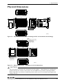
Physical Dimensions ............................................................................................................................. 69
6.
Appendix
71
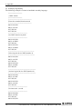
Watchdog Timer (WDT) Setting .......................................................................................................... 71
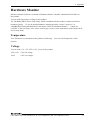
Hardware Monitor ................................................................................................................................. 75
Temperature ................................................................................................................................... 75
Voltage ........................................................................................................................................... 75
Q&A ...................................................................................................................................................... 76
Common to CPU-SB30 Series ...................................................................................................... 76
For CPU-SB303-FIT, CPU-SB304-FIT-400 only........................................................................ 77
For CPU-SB303-FIT-3F, CPU-SB304-FIT-45F only .................................................................. 78
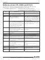
Difference from CPU-SB20/xxx(FIT)GY............................................................................................ 80
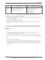
Precautions when Replacing CPU-SB20/xxx(FIT)GY with This Product.................................. 81
Difference from CPU-SB303-FIT Series ............................................................................................. 82
CPU-SB303-FIT, CPU-SB303-FIT-3F, CPU-SB304-FIT-400, CPU-SB304-FIT-45F
v
vi
CPU-SB303-FIT, CPU-SB303-FIT-3F, CPU-SB304-FIT-400, CPU-SB304-FIT-45F
1. Before Using the Product
1. Before Using the Product
This section explains information you need to know about this product before you use it.
About the Module
Operated by an OS such as Windows XP, this microcontroller unit can be used as a general-purpose PC
or a controller for a measurement/control/communication device from CONTEC F&eIT Series.
CPU-SB303 Series contains a power-saving high-performance Celeron (R) M processor 800MHz,
852GM chip set, 512MB of DDR SDRAM memory and communication interfaces such as USB2.0 and
1000BASE-T.
CPU-SB304 Series contains a power-saving high-performance Celeron (R) M processor 1GHz, 852GM
chip set, 512MB of DDR SDRAM memory and communication interfaces such as USB2.0 and
1000BASE-T.
The adoption of a heat sink provides a completely naturally air-conditioned (fanless) environment.
These products enable functional expansion when an F&eIT Series device is stack-connected to the
F&eIT I/F.
This product is faster (processing speed: approx. 6 times faster (CPU-SB304 : approx. eight times
faster)) and functionally more advanced (USB2.0, RS-232C and LAN: doubled) than the previous
CPU-SB20 Series products.
For more details on the differences from the conventional products, refer to “Chapter6 Differences from
CPU-SB20/xxx(FIT)GY”.
-
Base model
CPU-SB303-FIT, CPU-SB304-FIT-400
: (Memory 512MB, model without OS, CF)
OS pre-installed model
CPU-SB303-FIT-3F, CPU-SB304-FIT-45F
: (Memory 512MB, model with Windows XP
Embedded, CF 2GB)
Features
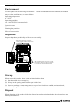
- Fits a PC with expansion capability into a small size (94.0(W) x 120.0(D) x 74.7(H)).
Encased in a compact cabinet (94.0(W) x 120.0(D) x 74.7(H)), this product has a range of interfaces
such as VGA, USB2.0 x 4, RS-232C x 2, LAN x 2 (1000BASE-T, 100BASE-TX), audio and F&eIT I/F
(for F&eIT Series device modules). This product also has the Secondary IDE Connector that can be
connected to an external CD-ROM/DVD-ROM drive.
- Ultra-low voltage Celeron M 800MHz, 852GM chip set, and 512MB of memory
(CPU-SB303-FIT, CPU-SB303-FIT-3F)
The product has a power-saving, high-performance, ultra-low voltage Intel (R) Celeron (R) M processor
with 800MHz (FSB: 400MHz), Intel (R) 852GM chip set, and 512MB of memory.
It is a faster and functionally more advanced model than the previous CPU-SB20 Series products, with
approximately 6-time faster processing speed.
CPU-SB303-FIT, CPU-SB303-FIT-3F, CPU-SB304-FIT-400, CPU-SB304-FIT-45F
1
1. Before Using the Product
- Ultra-low voltage Celeron M 1GHz, 852GM chip set, and 512MB of memory
(CPU-SB304-FIT-400, CPU-SB304-FIT-45F)
The product has a power-saving, high-performance, ultra-low voltage Intel (R) Celeron (R) M processor
with 1GHz (FSB: 400MHz), Intel (R) 852GM chip set, and 512MB of memory.
It is a faster and functionally more advanced model than the previous CPU-SB20 Series products, with
approximately 8-time faster processing speed.
- The adoption of a fan-less, CF card configuration providing high levels of reliability and quietness
The adoption of a heat sink provides a fanless environment, while the use of a CF card as a storage
device ensures high levels of reliability and quietness. In addition, from a full consideration of safety,
the CF card slot comes with a metal bracket to prevent the card from being accidentally disconnected.
- A wide range of power supplies (12 - 24VDC) supported
Supporting a wide range of power supplies (12 - 24VDC), the product can be used under various power
conditions.
- It is possible to operate by OS such as Windows XP. (CPU-SB303-FIT, CPU-SB304-FIT-400)
This product supports a variety of applications as a compact embedded controller based on Microsoft
Windows XP Professional, Embedded, Windows 2000, Linux and PC-DOS.
- Possibly used as a controller for a measurement/control/communication device from the F&eIT Series
This product can be used as a controller for a measurement/control/communication device from the
F&eIT Series.
The measurement/control/communication devices which can be used include digital I/O, analog I/O and
serial communication modules.
- Up to eight F&eIT Series device modules can be connected to the F&eIT I/F
The F&eIT I/F can accommodate up to eight F&eIT Series device modules (maximum total current of
each module is 3A or less).
- Possibly installed in 35mmDIN rail
A detachable metal installation part for attaching the main unit to a 35mm DIN rail is bundled by
default, which can be used according to the installation conditions. The system features a unique
configuration for its connection to a module on the side in a stacking manner, which allows you to
configure the system simply and elegantly without using backplanes and other connecting devices.
2
CPU-SB303-FIT, CPU-SB303-FIT-3F, CPU-SB304-FIT-400, CPU-SB304-FIT-45F
1. Before Using the Product
Verified Operating Systems
Operating system for which the CPU-SB303-FIT, CPU-SB304-FIT-400 (Model which has no OS)
operation has been confirmed is as follows.
-
Microsoft Windows XP Professional, Embedded
Microsoft Windows 2000 Professional
IBM PC-DOS 2000 Ver.7.0
TurboLinux 10 Server (Linux 2.6.8-1 kernel)
* Verified Operating Systems : Basic OS operation and VGA, LAN and sound driver operation has
been confirmed. CONTEC does not guarantee that all OS functions
will operate correctly.
* You can build a Windows XP or Windows 2000 SP3/SP4 environment on the CPU-SB303-FIT,
CPU-SB304-FIT-400 by installing the OS using a retail USB-based CD-ROM drive or FDD. You
can also install another OS such as DOS if you prepare a retail USB CD-ROM drive supported by a
startup disk for the OS.
CAUTION
It is not possible to operate by Microsoft Windows 2000 Professional in enhancement
odule SMC-2DL-FIT.
CPU-SB303-FIT, CPU-SB303-FIT-3F, CPU-SB304-FIT-400, CPU-SB304-FIT-45F
3
1. Before Using the Product
Support Software
You should use CONTEC support software according to your purpose and development environment.
Driver library API-SBP(W32) (Available for downloading (free of charge) from the CONTEC web
site.)
The CPU-SB30Series is the Windows version driver library software that provides products in the form of Win32 API
functions (DLL).
Various programming languages such as Visual Basic and Visual C++ can be used to create
high-speed application software which maximizes the features of the F&eIT module.
In addition, a diagnostic
program, which is useful for operation verification, is also provided.
< Operating environment >
OS
Windows XP, 2000, Me, 98, etc..
Adaptation language
Visual C++, Visual Basic, etc..
You can download the updated version from the CONTEC’s Web site (http://www.contec.com/fit/page5.htm).
For
more details on the supported OS, applicable language and new information, please visit the CONTEC’s Web site.
List of Options
CF Card (CPU-SB303-FIT, CPU-SB304-FIT-400)
- CF-1GB-A
1GB CompactFlash for Fix Disk
- CF-2GB-A
2GB CompactFlash for Fix Disk
- CF-4GB-A
4GB CompactFlash for Fix Disk
- CF-8GB-A
8GB CompactFlash for Fix Disk
CD-ROM/DVD-ROM drive
- IPC-CDD-03
CD-ROM/DVD-ROM drive *1
- IPC-CDC-03
Connection cable for CD-ROM/DVD drive (400mm)
*1
4
Please purchase the optional connection cable [IPC-CDC-03].
CPU-SB303-FIT, CPU-SB303-FIT-3F, CPU-SB304-FIT-400, CPU-SB304-FIT-45F
1. Before Using the Product
Customer Support
CONTEC provides the following support services for you to use CONTEC products more efficiently
and comfortably. No driver software is provided with this module. Please download the latest
drivers from the CONTEC web site (http://www.contec.com/). Documents including important notes
on the use of the module are also posted on the web site. Please visit the CONTEC web site before
using the module.
Web Site
Japanese
English
Chinese
http://www.contec.co.jp/
http://www.contec.com/
http://www.contec.com.cn/
Latest product information
CONTEC provides up-to-date information on products.
CONTEC also provides product manuals and various technical documents in the PDF.
Free download
You can download updated driver software and differential files as well as sample programs available in
several languages.
Note!
For product information
Contact your retailer if you have any technical question about a CONTEC product or need its price,
delivery time, or estimate information.
Limited One-Year Warranty
CONTEC products are warranted by CONTEC CO., LTD. to be free from defects in material and
workmanship for up to one year from the date of purchase by the original purchaser.
Repair will be free of charge only when this device is returned freight prepaid with a copy of the
original invoice and a Return Merchandise Authorization to the distributor or the CONTEC group office,
from which it was purchased.
This warranty is not applicable for scratches or normal wear, but only for the electronic circuitry and
original modules. The warranty is not applicable if the device has been tampered with or damaged
through abuse, mistreatment, neglect, or unreasonable use, or if the original invoice is not included, in
which case repairs will be considered beyond the warranty policy.
How to Obtain Service
For replacement or repair, return the device freight prepaid, with a copy of the original invoice. Please
obtain a Return Merchandise Authorization number (RMA) from the CONTEC group office where you
purchased before returning any product.
* No product will be accepted by CONTEC group without the RMA number.
Liability
The obligation of the warrantor is solely to repair or replace the product. In no event will the
warrantor be liable for any incidental or consequential damages due to such defect or consequences that
arise from inexperienced usage, misuse, or malfunction of this device.
CPU-SB303-FIT, CPU-SB303-FIT-3F, CPU-SB304-FIT-400, CPU-SB304-FIT-45F
5
1. Before Using the Product
Safety Precautions
Understand the following definitions and precautions to use the product safely.
Safety Information
This document provides safety information using the following symbols to prevent accidents resulting
in injury or death and the destruction of equipment and resources. Understand the meanings of these
labels to operate the equipment safely.
DANGER
DANGER indicates an imminently hazardous situation which, if not avoided, will
result in death or serious injury.
WARNING
WARNING indicates a potentially hazardous situation which, if not avoided, could
result in death or serious injury.
CAUTION
CAUTION indicates a potentially hazardous situation which, if not avoided, may
result in minor or moderate injury or in property damage.
Handling Precautions
DANGER
Please do not use the product in environments subject to flammable and corrosive gas.
it can bring on exploding, fire, electric shock and trouble.
Otherwise,
CAUTION
-
Do not use or store the equipment in a hot or cold place, or a place that is subject to severe
temperature changes.
Examples:
- Under direct sunlight
- Near a heat source
-
Do not use or store the equipment in a place that is subject to extreme humidity or dust. It will be
extremely dangerous to use the equipment when its interior is contaminated with water or liquid, or
conducting debris. When using the equipment in an environment that is subject to water or
conducting debris, consideration should be given to the installation of a control panel with a
structure that keeps dust out.
-
Do not use or store the equipment in a place that is subject to shock or vibrations.
-
Do not use or store the product near equipment generating a strong magnetic field or radio waves.
It may cause malfunction.
-
Do not use or store the equipment in air with diffused chemicals or in an environment in which the
equipment can come into contact with chemicals.
-
When attaching or detaching a module or a connector, please be sure that the power cable for the
system is unplugged from the outlet.
-
Do not modify this product. CONTEC will bear no responsibility for any problems, etc., resulting
from modifying this product.
6
CPU-SB303-FIT, CPU-SB303-FIT-3F, CPU-SB304-FIT-400, CPU-SB304-FIT-45F
1. Before Using the Product
-
-
-
If you notice any malfunction or abnormal conditions (such or a strange odor or overheating),
please unplug the power cord and contact your retailer.
To connect with peripherals, use a grounded, shielded cable.
To clean this product, gently wipe it with a soft cloth soaked with water or a neutral detergent. Do
not use benzene, a thinner, or other volatile solvents as they can cause the coating to discolor or
peel off.
Life of the components
Battery ... A primary lithium battery is used to back up the internal clock/calendar and the CMOS
RAM. When the power is not drawn and the battery is stored at 25°C, it will last over
10 years. For changing a battery, contact your retailer.
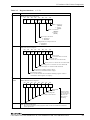
Regarding “FCC PART 15 Class A Notice”
The ferrite core must be installed in the following each cable so that this product may suit the
above-mentioned standard. Leave "Secondary IDE" pins unconnected.
CPU-SB303-FIT,CPU-SB303-FIT-3F
Port
Name
Maker
Turn
LAN 100M
LAN 1000M
E04SR301334
E04SR301334
SEIWA
SEIWA
2
2
LINE OUT
E04SR200935A
SEIWA
2
MIC
E04SR200935A
SEIWA
2
POWER
E04SR200935A
SEIWA
1
USB
E04SR301334
SEIWA
3
CPU-SB304-FIT- 400,CPU-SB304-FIT- 45F
Port
-
Name
Maker
Turn
LINE OUT
MIC
E04SR170730A
E04SR170730A
SEIWA
SEIWA
4
4
POWER
E04SR401938
SEIWA
4
Regarding “EMC Instruction Class A Notice”
The ferrite core must be installed in the following each cable so that CPU-SB304-FIT Series may
suit the above-mentioned standard. (CPU-SB303-FIT Series does not support the CE standard.)
Paste the attached IDE connector protective label to the secondary IDE.
CPU-SB304-FIT- 400, CPU-SB304-FIT- 45F
Port
MONITOR
MIC
Name
E04SR170730A
E04SR170730A
Maker
SEIWA
SEIWA
Turn
1
4
LINE OUT
E04SR170730A
SEIWA
4
POWER
E04SR401938
SEIWA
4
CPU-SB303-FIT, CPU-SB303-FIT-3F, CPU-SB304-FIT-400, CPU-SB304-FIT-45F
7
1. Before Using the Product
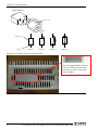
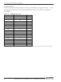
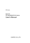
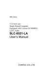
- Image diagram
Ferrite core
Ferrite core
Cable
TURN : 1
TURN : 2
TURN : 3
TURN : 4
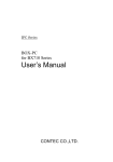
Pasting figure of IDE connector protective label
Paste the attached IDE connector
protective label so that the IDE
connector on side of main body
may be hidden.
8
CPU-SB303-FIT, CPU-SB303-FIT-3F, CPU-SB304-FIT-400, CPU-SB304-FIT-45F
1. Before Using the Product
FCC PART 15 Class A Notice
NOTE
This equipment has been tested and found to comply with the limits for a Class A digital device,
pursuant to part 15 of the FCC Rules. These limits are designed to provide reasonable protection
against harmful interference when the equipment is operated in commercial environment.
This equipment generates, uses, and can radiate radio frequency energy and, if not installed and
used in accordance with the instruction manual, may cause harmful interference to radio
communications. Operation of this equipment in a residential area is likely to cause harmful
interference at his own expense.
WARNING TO USER
Change or modifications not expressly approved the manufacturer can void the user's authority to
operate this equipment.
CPU-SB303-FIT, CPU-SB303-FIT-3F, CPU-SB304-FIT-400, CPU-SB304-FIT-45F
9
1. Before Using the Product
Environment
Use this product in the following environment.
may overheat, malfunction, or cause a failure.
Operating temperature
If used in an unauthorized environment, the module
0 - 50ºC
Operating humidity
10 - 90%RH (No condensation)
Corrosive gases
None
Floating dust particles
Not to be excessive
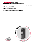
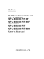
Inspection
Inspect the product periodically as follows to use it safely.
LINE OUT
- Check that the bus connector
of the module and its cable have
been plugged correctly.
L2
L1
Co mpa ct Flash
uSW
FG Vi - Vi+ POWER
COM1
COM2
12-24VDC
RESET
VGA
LINK 1000M ACT LINK 10/100M ACT
CF
MIC
CPU-SB30
CONTEC CO.,LTD.
MADE IN xxxxxx
- The ventilation slits are not covered,
and neither dust nor alien substance
is attached to the ventilation slits
Storage
When storing this product, keep it in its original packing form.
(1) Put the module in the storage bag.
(2) Wrap it in the packing material, then put it in the box.
(3) Store the package at room temperature at a place free from direct sunlight, moisture, shock,
vibration, magnetism, and static electricity.
Disposal
When disposing of the product, follow the disposal procedures stipulated under the relevant laws and
municipal ordinances.
10
CPU-SB303-FIT, CPU-SB303-FIT-3F, CPU-SB304-FIT-400, CPU-SB304-FIT-45F
2. Hardware Setup
2. Hardware Setup
Getting Started
Follow the following procedures to set up the CPU-SB30 series :
STEP1
Connecting the F&eIT series module
By referring to this chapter connects the F&eIT series module to the
CPU-SB30 series. When using the CPU-SB30 series on a standalone basis, go to STEP2.
STEP2
Connecting the cables
Connect the cables for the CRT and other external devices to the CPU-SB30 series.
STEP3
Turning on the power
After re-checking that STEPS 1 to 2 have been correctly performed, turn on the power. If
something goes wrong after the power is turned on, immediately turn off the power and
make sure that the system is correctly set up.
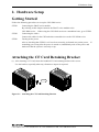
Attaching the CF Card Retaining Bracket
(1) After inserting a CF Card, fasten the bundled CF Card retaining bracket with a screw.
Use the bracket, especially when any vibration or impact is expected.
Figure 2.1. Attaching the CF Card Retaining Bracket
CPU-SB303-FIT, CPU-SB303-FIT-3F, CPU-SB304-FIT-400, CPU-SB304-FIT-45F
11
2. Hardware Setup
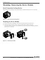
Mounting / Removing the Device Module
Stack Connection Locking Devices
This product has two openings (at the top and bottom) to which the locking devices are connected.
Figure 2.2. Stack connection locking device
Mounting the Device Module
(1) Insert the stack hook by aligning it with the hook insertion inlet for the other device.
(2) Mount the module onto this product, using the bundled F&eIT module fixing parts.
(If a stack connector protective cover is attached, the connection operation should be performed
after the cover is removed.)
Figure 2.3. Mounting the module
12
CPU-SB303-FIT, CPU-SB303-FIT-3F, CPU-SB304-FIT-400, CPU-SB304-FIT-45F
2. Hardware Setup
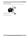
Removing the Module
Remove the F&eIT module fixing parts from the top and bottom to detach the joined modules.
Remove the module by inserting
a flat-head screw driver from
these products side. Too much force could break
the plastic clip. Please be careful.
Figure 2.4. Removing the Module
CPU-SB303-FIT, CPU-SB303-FIT-3F, CPU-SB304-FIT-400, CPU-SB304-FIT-45F
13
2. Hardware Setup
Mounting on / Removing a DIN Rail
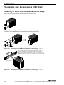
Mounting on a DIN Rail Installation Metal Fittings
Mount the DIN rail installation metal fittings onto the main unit.
(1) Remove the three screws found at the back of the main unit.
Figure 2.5. Mounting on a DIN Rail Installation Metal Fittings
<1/3>
(2) Mount the bundled DIN rail installation metal fittings with screws.
Figure 2.5. Mounting on a DIN Rail Installation Metal Fittings
<2/3>
It is recommended to use the following methods in order to
reinforce the DIN rail to which this product is connected.
- Keep the distance between screw positions short. (About 100mm)
- Place square washers (22-24mm) under the rail fixing screws.
(Make sure that the heads of the screws do not touch the back
of this product.)
Square washer
Figure 2.5. Mounting on a DIN Rail Installation Metal Fittings
14
<3/3>
CPU-SB303-FIT, CPU-SB303-FIT-3F, CPU-SB304-FIT-400, CPU-SB304-FIT-45F
2. Hardware Setup
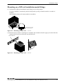
Mounting on a DIN rail installation metal fittings
(1) Pull down the DIN rail installation metal fitting lever on this product.
If a device module is connected, push the fixing hook up using a slotted screwdriver to make it
lockable.
(this should be done on all connected device modules.)
Press here to life
the fixing hook.
Figure 2.6. Mounting on a DIN rail
<1/3>
(2) Hook the unit (an object consisting of a controller and a module) from the upper part of the DIN rail,
and press the lower part of the unit onto the DIN rail.
35mm DIN rail
Figure 2.6. Mounting on a DIN rail
<2/3>
CPU-SB303-FIT, CPU-SB303-FIT-3F, CPU-SB304-FIT-400, CPU-SB304-FIT-45F
15
2. Hardware Setup
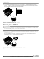
(3) Lift up the DIN rail installation fitting lever on this product. Attach the bundled lever fixing
screws. If a device module is connected, the fixing hook will be locked automatically; therefore,
the device module can be attached with a single motion.
COM1
FG Vi - Vi+ POWER
12-24VDC
COM2
RESET
Fixing hook
Figure 2.6. Mounting on a DIN rail
<3/3>
Removing from a DIN Rail
CAUTION
To disconnect any connected device from the other modules, remove all the device modules which
are connected to this product, from the DIN rail beforehand.
FG Vi - Vi+ POWER
COM1
12-24VDC
COM2
RESET
(1) Remove the lever fixing screws from the DIN rail installation fitting, then pull down the DIN rail
installation fitting lever.
If a device module is connected, pull down the fixing hook of the device module to unlock it.
(this should be done on all connected device modules.)
Figure 2.7. Removing the module from the DIN rail
16
<1/3>
CPU-SB303-FIT, CPU-SB303-FIT-3F, CPU-SB304-FIT-400, CPU-SB304-FIT-45F
2. Hardware Setup
(2) With the fixing hook unlocked, pull the lower part of this product toward you.
Figure 2.7. Removing the module from the DIN rail
<2/3>
(3) By lifting this product, you can easily remove it from the DIN rail.
Figure 2.7. Removing the module from the DIN rail
<3/3>
CPU-SB303-FIT, CPU-SB303-FIT-3F, CPU-SB304-FIT-400, CPU-SB304-FIT-45F
17
2. Hardware Setup
Connection Method
Supplying the Power to the Controller
(1) This product and a power supply unit (about 50W commercial power unit) are connected by using
the detachable connector either on the unit or module face.
Use a cable no longer than 40cm (AWG24 - 16). (No longer than 15cm for AWG28 and no longer
than 30cm for AWG26).
Compatible cables are AWG28 - 16. Strip the cable jacket off about 7mm. The fastening torque
for the cable core should be 0.22 - 0.25Nm.
CAUTION
The power supply for the device modules connected to the F&eIT I/F is supplied via the stack
connector.
For operating this product, power supply (12 - 24VDC) is required separately.
For more details on the power supply, refer to “Chapter5 Specifications - About power supply”.
18
CPU-SB303-FIT, CPU-SB303-FIT-3F, CPU-SB304-FIT-400, CPU-SB304-FIT-45F
2. Hardware Setup
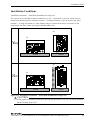
Installation Conditions
Installation orientation
(Floor/desk installation for single use)
The system can be installed in either orientation (1) or (2). Orientation (3) and (4), which does not
lend itself to heat dissipation, should be avoided. If using orientation (1), do not connect any other
modules. If using orientation (2), other modules may be connected but ensure a clearance on the
bottom side of at least 5.8mm by using the bundled rubber feet.
LINE OUT
(2)
CPU-SB30
FG Vi - Vi+ POWER
RESET
uSW
L1
MIC
L2
L2
L1
uSW
Compact Flash
RESET
Compact Flash
COM1
CF
LINK 1000M ACT LINK 10/100M ACT
COM1
12-24VDC
12-24VDC
COM2
COM2
FG Vi - Vi+ POWER
VGA
VGA
CPU-SB30
Yes
LINK 1000M ACT LINK 10/100M ACT
CF
MIC
(1)
LINE OUT
Floor
Floor
(4)
(3)
FG Vi - Vi+ POWER
RESET
uSW
L1
L2
MIC
LINE OUT
Compact Flash
12-24VDC
COM1
LINK 1000M ACT LINK 10/100M ACT
No
CF
VGA
CPU-SB30
COM2
Floor
Figure 2.8. Installation orientation
Floor
(Floor/desk installation for single use)
CAUTION
If this product is installed with the heat sink side up (direction of (1)), use it in the environment
that has cooling air (0.5m/s).
CPU-SB303-FIT, CPU-SB303-FIT-3F, CPU-SB304-FIT-400, CPU-SB304-FIT-45F
19
2. Hardware Setup
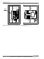
Installation orientation
(Wall/ceiling installation for single use)
The system can be installed in either orientation (5). Orientation (6), which does not lend itself to heat
dissipation, should be avoided. In orientation (5), the system can be connected to other modules. In
that case, however, install it on a DIN rail, leaving 45mm or more underneath.
Wall
(5)
Yes
CONTEC CO.,LTD.
MADE IN xxxxxx
(6)
No
CONTEC CO.,LTD.
MADE IN xxxxxx
Ceiling
Figure 2.9. Installation orientation
20
(Wall/ceiling installation for single use)
CPU-SB303-FIT, CPU-SB303-FIT-3F, CPU-SB304-FIT-400, CPU-SB304-FIT-45F
2. Hardware Setup
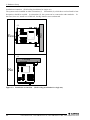
Spacing between the system unit and any surrounding objects
Secure a distance of at least 50mm between the top of the main unit (single use) and any surrounding
objects and also a distance of at least 10mm between each side of the unit and any surrounding objects.
To place the unit upright, use the bundled rubber feet to secure a distance of at least 5.8mm underneath.
If a device module is connected, secure a distance of at least 5.8mm at each side of the device module.
Do not locate the module in a fully enclosed housing.
This restriction does not apply if the side of the enclosure has ventilation slits next to the module.
50mm
or more
(Top)
10mm
or more
(Side)
10mm
or more
(Side)
50mm
or more
(Top)
10mm
or more
(Side)
CPU-SB30
VGA
COM2
CF
LINK 1000M ACT LINK 10/100M ACT
COM1
12-24VDC
Compact Flash
FG Vi - Vi+ POWER
RESET
uSW
L1
LINE OUT
50mm
or more
(Top)
5.8mm
or more
(Side)
LINE OUT
50mm
or more
(Top)
20mm
or more
(Side)
MIC
L2
5.8mm or more
(Bottom)
L2
L1
FG Vi - Vi+ POWER
COM1
12-24VDC
RESET
uSW
Compact Flash
LINK 1000M ACT LINK 10/100M ACT
VGA
COM2
5.8mm or more
(Bottom)
CF
MIC
CPU-SB30
Figure 2.10. Spacing between the module and any surrounding objects
<1/2>
CPU-SB303-FIT, CPU-SB303-FIT-3F, CPU-SB304-FIT-400, CPU-SB304-FIT-45F
21
2. Hardware Setup
50mm
or more
(Top)
5.8mm
or more
(Side)
LINE OUT
50mm
or more
(Top)
20mm
or more
(Side)
COM1
12-24VDC
L2
L1
FG Vi - Vi+ POWER
45mm
or more
(Bottom)
45mm
or more
(Bottom)
COM2
RESET
uSW
Compact Flash
VGA
LINK 1000M ACT LINK 10/100M ACT
CF
MIC
CPU-SB30
Figure 2.10. Spacing between the module and any surrounding objects
22
<2/2>
CPU-SB303-FIT, CPU-SB303-FIT-3F, CPU-SB304-FIT-400, CPU-SB304-FIT-45F
3. Functions of the Various Components
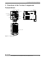
3. Functions of the Various Components
Nomenclature
LINE OUT
MIC
F&eIT I/F
L2
L1
Compact Flash
VGA
uSW
FG Vi - Vi+ POWER RESET
COM1
12-24VDC
COM
COM2
10/100BASE-TX
VGA
1000BASE-T
LINK 1000M ACT LINK 10/100M ACT
CF
LINE OUT
MIC
USB Compact Flash
CPU-SB30
L2
L1
uSW
RESET
CONTEC CO.,LTD.
MADE IN xxxxxx
POWER
Secondary IDE
Figure 3.1. Nomenclature
CPU-SB303-FIT, CPU-SB303-FIT-3F, CPU-SB304-FIT-400, CPU-SB304-FIT-45F
23
3. Functions of the Various Components
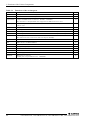
Table 3.1.
Functions of the various parts
Name
Function
COM
Serial port connector
(D-SUB 9-pin)
VGA
CRT connector
CompactFlash
Compact FLASH insertion connector
Page
25
(HD-SUB 15-pin)
31
(TYPE 1 or TYPE 2)
32
Any microdrive or CompactFlash that supports True IDE mode can be used.
Secondary IDE
Allows the optional CD-ROM/DVD-ROM drive to be connected, if the optional dedicated
cable is used.
33
CF LED
Compact FLASH access verification LED
34
POWR LED
Power-up verification LED
34
L1
User Programmable LED1 : The LED can be turned on or off via IO port 8800H[0].
34
L2
User Programmable LED2 : The LED can be turned on or off via IO port 8801H[0].
34
uSW
User Programmable Switch
The switch state (on or off) can be read from IO port 8802H[0].
34
RESET SW
Resets the CPU.
34
USB
USB connector (A TYPE USB2.0)
35
LINE OUT
Line out (φ3.5 PHONE JACK)
39
MIC
Microphone input (φ3.5 PHONE JACK)
39
10/100BASE-TX RJ-45 connector
36
1000BASE-T
RJ-45 connector
POWER
Power supply connector
F&eIT I/F
F&eIT series connector
(0.6mm pitch, 80-pin (FX-8C series,
24
37
(MC1,5/3-G-3,5 PHOENIX CONTACT)
39
40
HIROSE))
CPU-SB303-FIT, CPU-SB303-FIT-3F, CPU-SB304-FIT-400, CPU-SB304-FIT-45F
3. Functions of the Various Components
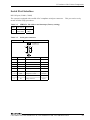
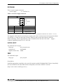
Serial Port Interface
RS-232Cport (COM1, COM2)
The system is equipped with two RS-232C-compliant serial port connector.
means of BIOS setup procedures.
Table 3.2.
SERIAL1 I/O address and interrupt (Factory setting)
COM
I/O address
Interrupt
1
3F8h-3FFh
IRQ 4
2
2F8h-2FFh
IRQ 3
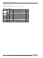
Table 3.3.
This port can be set by
Serial port connector
Connector used
D-SUB 9-pin (MALE)
UNC#4-40
inch screw
5
1
Pin No. Signal name
9
6
Meaning
Direction
1
CD
Carrier detect
2
RD
Received data
3
TD
Transmitted data
Output
Output
Input
Input
4
DTR
Data terminal ready
5
GND
Signal ground
-----
6
DSR
Dataset ready
Input
7
RTS
Request to send
8
CTS
Clear to send
Input
9
RI
Ring indicator
Input
Output
CPU-SB303-FIT, CPU-SB303-FIT-3F, CPU-SB304-FIT-400, CPU-SB304-FIT-45F
25
3. Functions of the Various Components
I/O addresses and commands
The following table shows COM1 addresses and commands :
Table 3.4.
I/O addresses
I/O address
DLAB
Read/Write
03F8h
0
W
Transmitter holding register
Register
THR
R
Receive buffer register
RBR
1
W
Divisor latch register (LSB)
DLL
03F9h
1
W
Divisor latch register (MSB)
DLM
0
W
Interrupt enable register
IER
03FAh
X
R
Interrupt ID register
IIR
03FBh
X
W
Line control register
LCR
MCR
03FCh
X
W
Modem control register
03FDh
X
R
Line status register
LSR
03FEh
X
R
Modem status register
MSR
03FFh
X
R/W
Scratch register
SCR
DLAB (Divisor Latch Access Bit) : value of bit 7 of line control register
26
CPU-SB303-FIT, CPU-SB303-FIT-3F, CPU-SB304-FIT-400, CPU-SB304-FIT-45F
3. Functions of the Various Components
Table 3.5.
Register functions
<1/3>
I/O address
03F8h
Description
THR: Transmitter Holding Register [DLAB=0]
D7 D6 D5 D4 D3
D2
D1
D0
bit0
LSB
bit7
MSB
Transmission data write-only register
03F8h
RBR: Reciever Buffer Register [DLAB=O]
D7 D6 D5 D4 D3
D2
D1
D0
bit0
LSB
bit7
MSB
Received data read-only register
03F8h
DLL: Divisor Latch (LSB) [DLAB=1]
D7 D6 D5 D4 D3
D2
D1
D0
bit0
LSB
bit7
MSB
Baud rate-setting register (LSB)
03F9h
DLH: Divisor Latch (MSB) [DLAB=1]
D7 D6 D5 D4 D3
D2
D1
D0
bit0
LSB
bit7
MSB
Baud rate-setting register (MSB)
03F9h
IER: Interrupt Enable Register [DLAB=0]
D7 D6 D5 D4 D3
D2
D1
0
0
0
0
EMS ELSI
D0
ETHREI ERDAI
Received data
Interrupt enabled
Received data register empty
Interrupt enabled
Receiver line status
Interrupt enabled
Modem status interrupt enabled
[Always used at 0.]
1: Interrupt enabled
0: Interrupt disabled
CPU-SB303-FIT, CPU-SB303-FIT-3F, CPU-SB304-FIT-400, CPU-SB304-FIT-45F
27
3. Functions of the Various Components
Table 3.5.
Register functions
<2/3>
I/O address
03FAh
Description
IIR : Interrupt Identification Register
D7
D6
D5
D4
D3
D2
0
0
0
0
D1
D0
0
Interrupt contents
bit2 bit1 bit0 Priority
03FBh
1: Interrupt not generated
0: Interrupt generated
Description
No interrupts generated
0
0
1
1
1
0
1
0
0
2
Interrupt generated when the receive buffer register
is ready. Interrupt cleared when the receive buffer is
read.
0
1
0
3
Interrupt generated when the transmitter holding
register is empty. Interrupt cleared when the IIR is
read or transmission data is written to the THR.
0
0
0
4 (low)
1 (high) Interrupt generated on overrun, parity, framing error,
or break. Interrupt cleared when the line status
register is read.
Modem status interrupts generated.(CTS, DSR, RI, CD)
Interrupt cleared when the modem status register is
read.
LCR : Line Control Register
D7
D6
D5
D4
D1 D0 Bit table
D3
D2
D1
D0
0
0
5
0
1
6
1
0
7
1
1
8
0 : 1 STOP bit
1 : 1.5 STOP bits for 5-bit length;
2 STOP bits for 6-, 7-, or 8-bit length
0 : Parity disabled
1 : Parity enabled
0 : Odd parity
1 : Even parity
0 : Stick parity disabled
1 : Stick parity enabled
0 : Break off
1 : Break signal sent
DLAB (divisor latch access bit)
For accessing the divisor latch register, set this bit to 1. For accessing
any other registers, set this bit to 0.
28
CPU-SB303-FIT, CPU-SB303-FIT-3F, CPU-SB304-FIT-400, CPU-SB304-FIT-45F
3. Functions of the Various Components
Table 3.5.
Register functions
<3/3>
I/O address
03FCh
Description
MCR: Modem Control Register
D7
D6
D5
D4
D3
0
0
0
Loop IRQ
D2
X
D1
D0
RTS DTR
DTR 0 : Inactive
[HIGH]
1 : Active
[LOW]
RTS 0 : Inactive
[HIGH]
1 : Active
[LOW]
Interrupt control bit
0 : Disabled
1 : Enabled
Diagnostic local loop-back test
0 : Disabled
1 : Enabled
03FDh
LSR: Line Status Register
D7
0
D6
D5
TEMT THRE
D4
D3
D2
D1
D0
BI
FE
PE
OE
DR
Data ready
('1' means data received)
Overrun error
('1' means an error detected)
Parity error ('1' means an error detected)
Framing error ('1' means an error detected)
Break interrupt ('1' means break detected)
Transmitter holding register empty
('1' means transmitter buffer empty)
Transmitter empty
('1' is set when both the transmitter holding register and the
transmitter shift register are empty)
03FEh
MSR : Modem Status Register
D7
D6 D5
D4 D3
DCD
RI
D2
D1
D0
DSR CTS DDCD TERI DDSR DCTS
Delta CTS
Delta DSR
Trailing edge RI
Delta data carrier detect
CTS
DSR
Because these
status bits are
not used in the
RS-485, the
data has no
meaning.
RI
DCD
03FFh
SCR : Scratchpad Register
This is an 8-bit data-saving register that is user-accessible for read and
write operations.
CPU-SB303-FIT, CPU-SB303-FIT-3F, CPU-SB304-FIT-400, CPU-SB304-FIT-45F
29
3. Functions of the Various Components
Setting the Baud rate
Software sets the baud rate by dividing the clock input (1.8432MHz) by an appropriate factor. A baud
rate can be set by writing one of the values listed in the table below into the Divisor Latch Register
(LSB, MSB):
Table 3.6.
Setting the Baud rate
Baud rate to be set
et in divisor register
Error (%)
50
2304
0.16
75
1536
0.16
110
1047
0.19
134 .5
857
0.10
150
768
0.16
300
384
0.16
600
192
0.16
1200
96
0.16
1800
64
0.16
2000
58
0.53
2400
48
0.16
3600
32
0.16
4800
24
0.16
7200
16
0.16
9600
12
0.16
19200
6
0.16
28800
4
0.16
38400
3
0.16
57600
2
0.16
115200
1
0.16
Ex.: For a 9600bps setting, write 00 (dec.) to divisor latch register (MSB), and 12 (dec.) to divisor latch register (LSB).
30
CPU-SB303-FIT, CPU-SB303-FIT-3F, CPU-SB304-FIT-400, CPU-SB304-FIT-45F
3. Functions of the Various Components
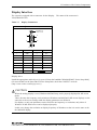
Display Interface
The system is equipped with a connector for the Display.
VGA(HD-SUB 15P).
Table 3.7.
The name of the connector is
Display Connnector
Connector used
HD-SUB 15-pin (MALE)
6
UNC#4-40
inch screw
1
11
5
15
10
Pin No.
Signal name
Pin No.
1
RED
9
N.C.
2
GREEN
10
GND
3
BLUE
11
N.C.
4
N.C.
12
N.C.
5
GND
13
HSYNC
6
GND
14
VSYNC
7
GND
15
N.C.
8
GND
Signal name
Display driver
Install the appropriate audio driver for your OS from the bundled CD-ROM [F&eIT Series Setup Disk].
(For more details on the latest F&eIT Series Setup Disk, check the CONTEC's web site
(http://www.contec.com/fit/page7.htm).)
CAUTION
When the analog display is used, Windows MS-DOS may not be properly displayed in full-screen
mode.
This is because the frequency and resolution of Windows and MS-DOS (full-screen display) are the
same due to the screen settings while the display parameters are different.
For display, as only one parameter can be stored for one frequency or resolution, only either of
Windows or MS-DOS screen can be displayed properly.
In this case, change the resolution or display frequency of Windows so that it is not the same as for
the MS-DOS display.
CPU-SB303-FIT, CPU-SB303-FIT-3F, CPU-SB304-FIT-400, CPU-SB304-FIT-45F
31
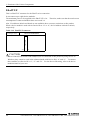
3. Functions of the Various Components
CompactFlash Slot
A CompactFlash compliant card slot is provided. You can use TYPE I or TYPE II memory cards or
microdrives that support True IDE mode. Also, you can boot the system from the CompactFlash
(hereafter referred to as "CF") by inserting a card containing an operating system (MS-DOS, Windows
and Linux, etc). Remember to format the CF before installing the OS. For formatting the
CompactFlash card, use a USB-based FDD.
The CPU-SB303-FIT-3F, CPU-SB304-FIT- 45F has a 2-GB CF card plugged in the slot, in which
Windows XP Embedded is already installed.
Power supply for the card
Available card voltages and current values for each slot are listed below :
Table 3.8.
Power supply for the card
Voltage
Current (Max)
+5V
Not supplied
+3.3V
500mA
+12V
Not supplied
Orientation of the CF card insertion
When inserting the CF card, direct the backside of the CF card (the side with edge of the card) to
[Ethernet connecter] side, and a side with narrow groove to the eject button of the CF slot, then insert.
Back
side
Groove: wide
Groove: narrow
Edge
Pin area
CAUTION
-
32
If you feel resistance when inserting the CF card, it could be a wrong insertion. If you further
insert forcefully, the CF connector and CF card could be broken.
When inserting in wrong orientation, the CF connector and CF card could be broken.
CPU-SB303-FIT, CPU-SB303-FIT-3F, CPU-SB304-FIT-400, CPU-SB304-FIT-45F
3. Functions of the Various Components
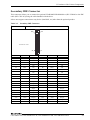
Secondary IDE Connector
This connector allows you to connect the optional CD-ROM/DVD-ROM drive (IPC-CDD-03 to the IDE
cable (IPC-CDC-03)) using the cable bundled with the drive.
It does not support connection to any device (hard disk, etc) other than the optional product.
Table 3.9.
Secondary IDE Connector
40-pin half pitch type (1.27mm pitch)
Connector used
B20
A20
B1
A1
Connector used
Pin No.
Signal name
Direction
Pin No.
Signal name
Direction
A1
RESET-
Output
B1
GND
-----
A2
DD7
I/O
B2
DD8
I/O
A3
DD6
I/O
B3
DD9
I/O
A4
DD5
I/O
B4
DD10
I/O
A5
DD4
I/O
B5
DD11
I/O
A6
DD3
I/O
B6
DD12
I/O
A7
DD2
I/O
B7
DD13
I/O
A8
DD1
I/O
B8
DD14
I/O
A9
DD0
I/O
B9
DD15
I/O
A10
GND
-----
B10
N.C.
-----
A11
DDRQ
Input
B11
GND
-----
A12
DIOW-
Output
B12
GND
-----
A13
DIOR-
Output
B13
GND
-----
A14
IOCHRDY
Input
B14
DALE
Output
A15
DDACK-
Output
B15
GND
-----
A16
INTRQ
Input
B16
N.C.
-----
A17
DA1
Output
B17
N.C.
-----
A18
DA0
Output
B18
DA2
Output
A19
CS1-
Output
B19
CS3-
Output
A20
DACT-
Output
B20
GND
-----
CPU-SB303-FIT, CPU-SB303-FIT-3F, CPU-SB304-FIT-400, CPU-SB304-FIT-45F
33
3. Functions of the Various Components
CF LED: Red
Illuminates when the CompactFlash is accessed.
Note that there is some variation between the specifications of CompactFlash cards. If you use a card
with different specifications, the LED may not illuminate or may remain permanently illuminated.
POWER LED: Green
Illuminates when the power is turned on.
L1: User Programmable LED1 Red
Writing "1" to bit 0 of IO port 8800H illuminates the L1 LED (red).
permitted.
Reading the IO port state is also
L2: User Programmable LED2 Green
Writing "1" to bit 0 of IO port 8801H illuminates the L2 LED (green).
also permitted.
Reading the IO port state is
uSW: User Programmable Switch
Reading bit 0 of IO port 8802H indicates the switch state. A value of "1" indicates the switch is
pressed and "0" indicates no pressed. This IO port bit is read-only.
RESET SW
Pressing this button triggers a reset.
34
CPU-SB303-FIT, CPU-SB303-FIT-3F, CPU-SB304-FIT-400, CPU-SB304-FIT-45F
3. Functions of the Various Components
USB ports
The system is provided with four USB interfaces compliant with the USB 2.0 standard (High/Full/Low
Speed).
The power supply capacity for each port is 500mA.
Before connecting a USB device that requires high current consumption to this product, make sure that
the current consumption does not exceed the power capacity of the power supply unit to be used.
This product supports the use of a USB-based floppy disk drive (“FDD”), allowing booting of various
OS (PC-DOS boot disk, Windows XP/2000 setup boot disk).
Booting from a USB CD-ROM drive is supported.
For details on how to install the OS, refer to the “CPU-SB303-FIT OS installation procedure” in the
bundled CD-ROM [F&eIT Series Setup Disk].
For details on the latest “CPU-SB303-FIT OS installation procedure”, visit to the CONTEC web site to
download.
Table 3.10.
Pin No.
USB connector
B1
B4
A1
A4
Signal name
Pin No.
Signal name
A1
USB0 Vcc
B1
USB1 Vcc
A2
USB0 -Data
B2
USB1 -Data
A3
USB0 +Data
B3
USB1 +Data
A4
USB0 GND
B4
USB1 GND
CAUTION
Although the USB controller of this product is compliant with the USB 2.0 standard
(High/Full/Low Speed), it may not function properly for some USB devices (bus-powered USB
hard disk unit, USB card reader, etc.).
CPU-SB303-FIT, CPU-SB303-FIT-3F, CPU-SB304-FIT-400, CPU-SB304-FIT-45F
35
3. Functions of the Various Components
Fast-Ethernet
The system is equipped with a Fast-Ethernet.
- Network mode
: 10/100BASE-TX
- Transmission rate*
: 10M/100Mbps
- Max. network path length
: 100m/segment
- Controller
: Built-in ICH4 (Intel)
* Operation at 100 Mbps requires a Category 5 cable.
Table 3.11. Ethernet connector
Connector used
RJ-45
8
1
Pin No.
Signal
Meamimg
1
TD+
Transmitted data (+)
2
TD-
Transmitted data (-)
3
RD+
Received data (+)
4
N.C.
Not connected
5
N.C.
Not connected
6
RD-
Received data (-)
7
N.C.
Not connected
8
N.C.
Not connected
Network status display LED
LINK : Link status indicator
ACT
: Data send/receive indicator
LAN driver
Install the appropriate LAN driver for your OS from the bundled CD-ROM [F&eIT Series Setup Disk].
(For more details on the latest F&eIT Series Setup Disk, check the CONTEC's web site
(http://www.contec.com/fit/page7.htm).)
36
CPU-SB303-FIT, CPU-SB303-FIT-3F, CPU-SB304-FIT-400, CPU-SB304-FIT-45F
3. Functions of the Various Components
Gigabit-Ethernet
The system is equipped with a Gigabit-Ethernet.
- Network mode
: 1000BASE-T
- Transmission rate*
: 10M/100M/1000M bps
- Max. network path length
: 100m/segment
- Controller
: 82541PI(Intel)
* Operation at 100 Mbps requires a Category 5 or more cable.
* Operation at 1000 Mbps requires a Category 5e or more cable.
Table 3.12. Gigabit-Ethernet connector
Connector used
RJ-45
8
1
Pin No.
Signal name
Meamimg
1
TRD+(0)
Transmit / receive data 0 (+)
2
TRD-(0)
Transmit / receive data 0 (-)
3
TRD+(1)
Transmit / receive data 1 (+)
4
TRD+(2)
Transmit / receive data 2 (+)
5
TRD-(2)
Transmit / receive data 2 (-)
6
TRD-(1)
Transmit / receive data 1 (-)
7
TRD+(3)
Transmit / receive data 3 (+)
8
TRD-(3)
Transmit / receive data 3 (-)
Network status display LED
LINK : Link status indicator
ACT
: Data send/receive indicator
LAN driver
Install the appropriate LAN driver for your OS from the bundled CD-ROM [F&eIT Series Setup Disk].
(For more details on the latest F&eIT Series Setup Disk, check the CONTEC's web site
(http://www.contec.com/fit/page7.htm).)
CAUTION
In case of CPU-SB304, range of operating guarantee temperature is 0 - 35°C when connecting the
1000BASE-T. If you use it in the range of 35 - 50°C, set it to 100BASE-TX or 10BASE-T.
CPU-SB303-FIT, CPU-SB303-FIT-3F, CPU-SB304-FIT-400, CPU-SB304-FIT-45F
37
3. Functions of the Various Components
How to set CPU-SB304 as 100BASE-TX or 10BASE-T
Windows XP
(1) Click [Start] button.
(2) Click [Control Panel].
(3) Click [Performance and Maintenance].
(4) Click [System] then [System Properties] window is displayed.
(5) Click [Hardware] then click [Device Manager].
(6) Click ‘+’ in [Network adapters] then double-click ‘Intel(R) PRO/1000 MT Network Connection’.
(7) Click [detailed setting] tab then select [Link speed and duplex].
(8) Click [Link Speed] tab and then select one setting from ‘100Mbps/Full Duplex’, ‘100Mbps/Half Duplex’,
‘10Mbps/Full Duplex’, or ‘10Mbps/Half Duplex’ in [Speed and Duplex] which suits the environment for
LAN connection.
38
CPU-SB303-FIT, CPU-SB303-FIT-3F, CPU-SB304-FIT-400, CPU-SB304-FIT-45F
3. Functions of the Various Components
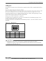
POWER
This is a power supply connector
- Power supply
: 12 - 24VDC±5%
Table 3.13. Power supply connector
Connector used
MC1,5/3-G-3,5(PHOENIX CONTACT)
Vi+
12 - 24VDC
ViFG
Pin No.
Signal name
1
Meaning
Vi+
Power supply (12 - 24VDC)
2
Vi-
Power supply (GND)
3
FG
Frame ground
Applicable plug (provided with module) :
MC1,5/3-ST-3,5 (Made by PHOENIX CONTACT) (For AWG28 - 16 cable)
The length of cable from the external power supply to the above connector must be no more than 40cm
for AWG24 - 16 cable, no more than 15cm for AWG28, and no more than 30cm for AWG26.
When connecting, remove approximately 7mm of insulation from the end of the cable. Apply a
conductor tightening torque of 0.22 - 0.25 Nm.
LINE OUT
The audio line OUT output.
Plug type
: φ3.5 pin jack stereo
Output level
: 8Ω 200mW.
Signal to Noise ratio : 90dB.
MIC
The audio MIC Input.
Plug type
: φ3.5 pin jack
Sound driver
Install the appropriate sound driver for your OS from the bundled CD-ROM [F&eIT Series Setup Disk].
(For more details on the latest F&eIT Series Setup Disk, check the CONTEC's web site
(http://www.contec.com/fit/page7.htm).)
CPU-SB303-FIT, CPU-SB303-FIT-3F, CPU-SB304-FIT-400, CPU-SB304-FIT-45F
39
3. Functions of the Various Components
F&eIT I/F
This is a F&eIT I/F connector for the F&eIT series connection.
It can connect up to eight device modules.
The maximum power to be supplied to the F&eIT I/F is 3A. Therefore, make sure that the total current
consumption of connected modules does not exceed 3A.
Also, I/O addresses 08xxh and 48xxh are not available due to resource restrictions to this product.
When a device module is used with its Device ID as “0” or “4”, the I/O address is 09xxh or 49xxh,
respectively.
Table 3.14. F&eIT I/F connector
Connector used
FX8C-80S-SV(HIROSE)
FX8C-80S-SV
1
A1
Available connector :
B1
FX8C-80P-SV (HIROSE)
CAUTION
When COM-2(FIT)GY and COM-1PD(FIT)GY are connected to this product by using the CF on
Windows, they cannot be used in the enhanced mode with Device ID’s “4” and “5”. To connect
three modules, use Device ID’s “6”, “C” and “D”. For the Device ID setting, refer to the device
module manual of your own.
40
CPU-SB303-FIT, CPU-SB303-FIT-3F, CPU-SB304-FIT-400, CPU-SB304-FIT-45F
3. Functions of the Various Components
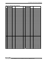
Table 3.15. F&eIT I/F pin assignments
No.
Signal
Dir
Description
No.
Signal
x86
Dir
Description
x86
A01 FG
Frame ground
B01
FG
A02 N.C.
Not connected
B02
N.C.
Frame ground
Not connected
A03 SA15
OUT
Address bus 15
B03
SA14
OUT
Address bus 14
A04 SA13
OUT
Address bus 13
B04
SA12
OUT
Address bus 12
A05 SA11
OUT
Address bus 11
B05
SA10
OUT
Address bus 10
A06 SA09
OUT
Address bus 09
B06
SA08
OUT
Address bus 08
A07 SA07
OUT
Address bus 07
B07
SA06
OUT
Address bus 06
A08 SA05
OUT
Address bus 05
B08
SA04
OUT
Address bus 04
A09 SA03
OUT
Address bus 03
B09
SA02
OUT
Address bus 02
A10 SA01
OUT
Address bus 01
B10
SA00
OUT
Reserved
B11
RESERVED
A11 RESERVED
A12 RESERVED
Address bus 00
Reserved
Reserved
B12
RST_x86#
IN
CPU reset signal
A13 SD00
IN/OUT
Data bus 00
B13
SD01
IN/OUT
Data bus 01
A14 SD02
IN/OUT
Data bus 02
B14
SD03
IN/OUT
Data bus 03
A15 SD04
IN/OUT
Data bus 04
B15
SD05
IN/OUT
Data bus 05
A16 SD06
IN/OUT
Data bus 06
B16
SD07
IN/OUT
Data bus 07
A17 SD08
IN/OUT
Data bus 08
B17
SD09
IN/OUT
Data bus 09
A18 SD10
IN/OUT
Data bus 10
B18
SD11
IN/OUT
Data bus 11
A19 SD12
IN/OUT
Data bus 12
B19
SD13
IN/OUT
Data bus 13
A20 SD14
IN/OUT
Data bus 14
B20
SD15
IN/OUT
Data bus 15
Ground
B21
GND
A21 GND
Ground
A22 AEN
OUT
Address enable signal
B22
IOCHCK#
IN
NMI signal
A23 IOR#
OUT
Read signal
B23
IRQ7
IN
Interrupt signal
A24 IOW#
OUT
Write signal
B24
IRQ5
IN
Interrupt signal
Ground
B25
GND
OUT
Bus clock
B26
IO_RST#
OUT
Reset signal
Ground
B27
CPUSEN
OUT
CPU ID
IN/OUT
Wait signal
B28
GND
Ground
B29
GND
Ground
A25 GND
A26 CLK8MHz
A27 GND
A28 IOCHRDY#
A29 GND
Ground
A30 RESETDRV
A31 IRQ9
IN
A32 RESERVED
Ground
ISA RESETDRV signal
B30
RESERVED
Reserved
Interrupt signal
B31
RESERVED
Reserved
Reserved
B32
RESERVED
ISA SBHE signal
B33
IOCS16#
A34 RESERVED
Reserved
B34
RESERVED
Reserved
A35 RESERVED
Reserved
B35
RESERVED
Reserved
A36 RESERVED
Reserved
B36
RESERVED
Reserved
A37 VCC
+5.0V power supply
B37
VCC
+5.0V power supply
A38 VCC
+5.0V power supply
B38
VCC
+5.0V power supply
A39 VCC
+5.0V power supply
B39
VCC
+5.0V power supply
A40 VCC
+5.0V power supply
B40
VCC
+5.0V power supply
A33 SBHE
IN/OUT
Reserved
IN
ISA IOCS16 signal
CPU-SB303-FIT, CPU-SB303-FIT-3F, CPU-SB304-FIT-400, CPU-SB304-FIT-45F
41
3. Functions of the Various Components
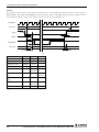
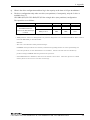
Remarks)
The symbol "#" at the end of an item represents negative logic.
B26 IO_RST#.
In an I/O module, normally a pin is reset by using pin
The signal B27 CPUSEN indicates a Low level output.
the rise edge is enabled.
The IRQx signal represents a signal for which
Total power ratings for the power supply pins: 5.0VDC, 3.0A.
CLK8MHz
SA15-SA0
tSA2
AEN
tIOW2
tAEN1
IOW#
tIOW1
tIOW
IOCHRDY#
tRDY1
tRDY
SD7-SD0
tWSD2
tWSD1
[ns]
Item
Address delay time
Code
Min.
Max.
-
tSA2
0
AEN delay time 1
tAEN2
30
-
IOW# delay time 2
tIOW2
100
-
IOW# delay time 1
tIOW1
100
-
IOW# pulse width
tIOW
16bit-225
8bit-520
-
IOCHRDY# delay
time
tRDY1
-
16bit-75
8bit-360
IOCHRDY# pulse
width
tRDY
125
15600
Data delay time
tWSD1
16bit-123
8bit-140
-
Data hold time
tWSD2
45
-
Figure 3.2. F&eIT I/F I/O write cycle
42
CPU-SB303-FIT, CPU-SB303-FIT-3F, CPU-SB304-FIT-400, CPU-SB304-FIT-45F
3. Functions of the Various Components
CLK8MHz
SA15-SA0
tSA2
AEN
tIOR2
IOR#
tAEN1
tIOR1
tIOR
IOCHRDY#
tRDY1
tRDY
SD7-SD0
tRSD1
tRSD2
[ns]
Item
Address delay time
Code
Min.
Max.
tSA2
0
-
AEN delay time 1
tAEN1
30
-
IOW# delay time 2
tIOR2
100
-
IOW# delay time 1
tIOR1
100
-
IOW# pulse width
tIOR
16bit-160
8bit-520
-
tRDY1
-
16bit-75
8bit-360
IOCHRDY# pulse width
tRDY
125
15600
Data setup time
tRSD1
24
-
Data hold time
tRSD2
45
-
IOCHRDY# delay time
Figure 3.3. F&eIT I/F I/O read cycle
IRQ
tIRQ1
Item
tIRQ2
Code
Min.
Recovery time
tIRQ2
125
Max.
-
Data hold time
tIRQ2
*1
*1
*1 : High level must be maintained until the completion of interrupt processing.
Figure 3.4. F&eIT I/F interrupt cycle
CPU-SB303-FIT, CPU-SB303-FIT-3F, CPU-SB304-FIT-400, CPU-SB304-FIT-45F
43
3. Functions of the Various Components
44
CPU-SB303-FIT, CPU-SB303-FIT-3F, CPU-SB304-FIT-400, CPU-SB304-FIT-45F
4. BIOS Setup
4. BIOS Setup
BIOS Setup
BIOS setup sets various settings during startup. When using the system for the first time, be sure to
run BIOS setup. Once set up, the specified details will be backed up.
This chapter describes the setup utility built into BIOS.
The BIOS setup screen allows you to set the time, specify the boot device and make hardware settings
such as settings for COM and other embedded devices.
CAUTION
-
To restore the default settings, press <F9> on the setup screen.
-
Please note that set data might not be maintained in the state that the board is not built into the
system case while transporting it though set data in CMOS is backed up with the battery.
CPU-SB303-FIT, CPU-SB303-FIT-3F, CPU-SB304-FIT-400, CPU-SB304-FIT-45F
45
4. BIOS Setup
Starting the Setup Screen
To start the PhoenixBIOS Setup utility:
Turn on or reboot your system. PhoenixBIOS displays this message:
Press <F2> to enter SETUP
Pressing <F2> displays the Main Menu, which looks like this:
Main Menu
Main
Advanced
Security
Power
System Time:
HH: MM : SS
System Date:
MM / DD / YYYY
> Primary Master
[Auto] *2
> Primary Slave
[Auto]
> Secondary Master
[Auto]
> Secondary Slave
[Auto]
System Memory
XxxKB
Extended Memory
XxxxxKB
PC_Health
Boot
Exit
*1
(General key operation help)
*1
It shows Item Specific Help, if the item has a help information.
*2
The “>” mark indicates it has a submenu.
Figure 4.1. Main Manu Window (Factory Settings)
46
CPU-SB303-FIT, CPU-SB303-FIT-3F, CPU-SB304-FIT-400, CPU-SB304-FIT-45F
4. BIOS Setup
Keystrokes
Use the keys listed in the legend bar on the bottom to make your selections or exit the current menu.
The chart on the following page describes the legend keys and their alternates:
Key
Function
<F1> or <Alt-H>
General Help window (See below).
<Esc>
Exit this menu.
← or → arrow keys
Select a different menu.
↑ or ↓ arrow keys
Move cursor up and down.
<Tab> or <Shift-Tab>
Cycle cursor up and down.
<Home> or <End>
Move cursor to top or bottom of window.
<PgUp> or <PgDn>
Move cursor to next or previous page.
<F5> or <->
Select the Previous Value for the field.
<F6> or <+> or <Space>
Select the Next Value for the field.
<F9>
Load the Default Configuration values for this menu.
<F10>
Load the Previous Configuration values for this menu.
<Enter>
Execute Command or Select P Submenu.
<Alt-R>
Refresh screen.
You can make the following selections on the Main Menu itself. Use the sub menus for other selections.
Feature
Options
Description
System Time
HH:MM:SS
System Date
MM/DD/YYYY
Set the system date.
Primary Master
This field is set to
[AUTO] by default. You
can leave it intact for
normal use.
Set to the type of the drive on primary IDE master.
Primary Slave
Secondary Master
Secondary Slave
Set the system time.
Set to the type of the drive on primary IDE master. *1
Set to the type of the drive on primary IDE master.
Set to the type of the drive on primary IDE master. *2
System Memory
N/A
Displays amount of conventional memory detected
during boot up.
Extended Memory
N/A
Displays the amount of extended memory detected
during boot up.
*1
No drive can be connected to the Primary Slave.
*2
Please do not connect it of the slave alone.
You can set the boot sequence of the bootable drives by selecting the Boot Sequence from the main
menu or opening the Boot Menu.
CPU-SB303-FIT, CPU-SB303-FIT-3F, CPU-SB304-FIT-400, CPU-SB304-FIT-45F
47
4. BIOS Setup
Primary/Secondary Master, Slave
The Primary/Secondary Master and Slave sub-menus accessed from the Main Menu control these types
of devices:
Hard-disk drives
- CF, Microdrive
- CD-ROM drives
This product supports IDE port for both primary and secondary.
As the CF slot is assigned to the Primary Master, no drive can be connected to the Primary Slave.
Each IDE port supports Master drives and optional Slave drives in one of the following combinations :
- 1 Master
- 2 Master
- 2 Master, 1 Slave
CAUTION
Change this setting, only when an IDE drive which cannot be successfully set by the AUTO setting
(e.g. an old model that does not support automatic setting) is installed.
48
CPU-SB303-FIT, CPU-SB303-FIT-3F, CPU-SB304-FIT-400, CPU-SB304-FIT-45F
4. BIOS Setup
Advanced Menu
This chapter allows you to configure your system for basic operation. You have the opportunity to
select the system’s default speed, boot-up sequence, keyboard operation, shadowing and security.
Main
Advanced
Security
Power
PC_Health
Boot
Reset Configuration Data:
[No]
Installed O/S:
[WinXP]
Large Disk Access Mode:
[DOS]
APIC - IO APIC Mode:
[Disabled]
Exit
>Cache Memory Features
>Memory Features
>PCI Features
>IDE Features
>Video Features
>LAN Features
>USB Features
>Audio Features
>IO Features
>Keyboard Features
>Boot Features
Figure 4.2. Advanced Menu Window (Factory Settings)
Reset Configuration Data
Please use it with No usually. There is a trouble such as OS's being not able to start with the device
newly added to the system and to make it reset system configuration data (ESCD) and restructure, make
it to Yes. After resetting, it automatically returns to No.
Installed O/S
The operating system most frequently used is selected.
Large Disk Access Mode
Normally, set to "DOS".
CPU-SB303-FIT, CPU-SB303-FIT-3F, CPU-SB304-FIT-400, CPU-SB304-FIT-45F
49
4. BIOS Setup
APIC - IO APIC Mode
Enable or disable the APIC operation.
If you change the setting, note that you have to reinstall the OS.
Be sure to use it in “Disabled” in case of the XP Embedded CPU-SB303-FIT-36 and
CPU-SB304-FIT-456.
APIC - IO APIC Mode setting is corresponding to the BIOS Ver.1.21 or later.
Cache Memory Features
Main
Advanced
Security
Power
PC_Health
Boot
Exit
Cache Memory Features
Memory Cache:
[Enabled]
Cache System BIOS area:
[Write Protect]
Cache Video BIOS area:
[Write Protect]
Cache BASE 0-512k:
[Write Back]
Cache BASE 512k-640k:
[Write Back]
Cache Extended Memory area:
[Write Back]
Cache A000 - AFFF:
[Disabled]
Cache B000 - BFFF:
[Disabled]
Cache C800 - CBFF:
[Write Protect]
Cache CC00 - CFFF:
[Write Protect]
Cache D000 - D3FF:
[Disabled]
Cache D400 - D7FF:
[Disabled]
Cache D800 - DBFF:
[Disabled]
Cache DC00 - DFFF:
[Disabled]
Cache E000 - E3FF:
[Disabled]
Cache E400 - E7FF:
[Write Protect]
Cache E800 - EBFF:
[Write Protect]
Cache EC00 - EFFF:
[Write Protect]
Figure 4.3. Cache Memory Features Window (Factory Settings)
Please use it basically by the default setting.
Cache System BIOS:
System BIOS is cached and the performance is improved.
Cache Video BIOS:
Video BIOS is cached and the performance is improved.
50
CPU-SB303-FIT, CPU-SB303-FIT-3F, CPU-SB304-FIT-400, CPU-SB304-FIT-45F
4. BIOS Setup
Memory Features
Main
Advanced
Security
Power
PC_Health
Boot
Exit
Memory Features
Enable memory gap:
[Disabled]
Figure 4.4. Memory Features Window (Factory Settings)
Please use basically with default setting.
Feature
Enable memory gap
Options
Disabled
Enabled
Description
If enabled, turn system RAM off to free address space for
use with an option board. Either a 128K conventional
memory gap starting at 512KB, or a 1MB extended memory
gap, starting at 15MB, will be created in system RAM.
PCI Features
Main
Advanced
Security
Power
PC_Health
Boot
Exit
PCI Features
> PCI IRQ
Figure 4.5. PCI Features Window (Factory Settings)
Please use it basically by the default setting.
PCI IRQ
Displays the PCI IRQ setup submenu. You can assign IRQs to individual PCI IRQ lines. All PCI slots
are connected to IRQ10 by default. However, this setting is set to “Disabled” and IRQ is allocated
against the PCI device when you set the APIC - IO APIC Mode to “Enabled” in the “Advanced Menu”.
CPU-SB303-FIT, CPU-SB303-FIT-3F, CPU-SB304-FIT-400, CPU-SB304-FIT-45F
51
4. BIOS Setup
IDE Features
Main
Advanced
Security
Power
PC_Health
Boot
Exit
IDE Features
IDE - Device 31, Function 1:
[Enabled]
Local Bus IDE adapter:
[Both]
Hard Disk Pre-Delay:
[Disabled]
SMART Device Monitoring:
[Enabled]
Figure 4.6. IDE Features Window (Factory Settings)
Please use basically with default setting.
Feature
Options
Description
IDE - Device 31,
Function 1
Disabled
Enabled
Enable or Disable the IDE Controller.
Local Bus IDE adapter
Disabled
Enabled
Primary
Both
The IDE channels setting.
Hard Disk Pre-Delay
Disabled
3 seconds
6 seconds
9 seconds
12 seconds
15 seconds
18 seconds
21 seconds
30 seconds
Adds a delay before the first access of a hard disk by the
BIOS. Some hard disks hang if accessed before they have
initialized themselves. This delay ensures the hard disk
has initialized after power up, prior to being accessed.
SMART device
monitoring
Disabled
Enabled
Turn on Self-Monitoring Analysis-Reporting Technology,
which monitors condition of the hard drive and reports
when a catastrophic IDE failure is about to happen
52
CPU-SB303-FIT, CPU-SB303-FIT-3F, CPU-SB304-FIT-400, CPU-SB304-FIT-45F
4. BIOS Setup
Video Features
Main
Advanced
Security
Power
PC_Health
Boot
Exit
Video Features
IGD - Memory Size:
[UMA = 8MB]
Internal DDC ROM
[Enabled]
Splash Screen Size
[1024x768]
Figure 4.7. Video Features Window (Factory Settings)
Please use basically with default setting.
Feature
Options
Description
IGD - Memory Size
UMA = 1M
UMA = 8M
UMA = 16M
UMA = 32M
When Enabled, a fixed VGA frame buffer from A000h - BFFFh and
a CPU-to-PCI write buffer are implemented.
Internal DDC ROM
Disabled
Enabled
Enables or disables the internal DDC ROM for the CRT interface.
When “Enabled”, it reads DDC data from the internal DDC ROM.
In normal cases, use it while “Enabled”.
Splash Screen Size
640 x 480
Select the panel device resolution.
800 x 600
1024 x 768
1280 x 1024
LAN Features
Main
Advanced
Security
Power
PC_Health
Boot
Exit
LAN Features
Internal LAN - Device 8:
[Enabled]
Figure 4.8. LAN Features Window (Factory Settings)
Please use it basically by the default setting.
Feature
Options
Internal LAN - Device 8 Disabled
Enabled
Description
Setting item to “Enabled” will allow the LAN to operate correctly.
Setting item to “Disabled” will remove the LAN from PCI
configuration space.
LAN : 10/100BASE-TX
CPU-SB303-FIT, CPU-SB303-FIT-3F, CPU-SB304-FIT-400, CPU-SB304-FIT-45F
53
4. BIOS Setup
USB Features
Main
Advanced
Security
Power
PC_Health
Boot
Exit
USB Features
USB - Device 29, F7:
[Enabled]
Legacy USB Support
[Enabled]
Figure 4.9. USB Features Window (Factory Settings)
Please use basically with default setting. Use the Legacy USB Support during installation, when
necessary. Legacy USB Support setting is supported from BIOS Ver.1.11 and later.
Feature
Options
Description
USB - Device 29, F7
Disabled
Enabled
Enabled or disables the USB2.0
Legacy USB Support
Disabled
Enabled
Enabled or disables the Legacy USB
Audio Features
Main
Advanced
Security
Power
PC_Health
Boot
Exit
Audio Features
AC97A - Device 31, Function 5:
[Enabled]
Figure 4.10. Audio Features Window (Factory Settings)
Please use it basically by the default setting.
AC97A - Device 31, Function 5: Enables or disables the chipset Audio device setting.
54
CPU-SB303-FIT, CPU-SB303-FIT-3F, CPU-SB304-FIT-400, CPU-SB304-FIT-45F
4. BIOS Setup
I/O Features
Main
Advanced
Security
Power
PC_Health
Boot
Exit
IO Features
Serial port A:
[Enabled]
Base I/O address:
[3F8]
Interrupt:
[IRQ 4]
Serial port B:
[Enabled]
Base I/O address:
[2F8]
Interrupt:
[IRQ 3]
Figure 4.11. IO Features Window (Factory Settings)
The CPU communicates with external devices such as printer through devices called Input/Output (I/O)
ports such as serial and parallel ports. Theses I/O devices require the use of system resources such as
I/O addresses and interrupt lines. If the devices support Plug and Play, ports can be assigned to them
during posting by BIOS as well as the Operating System. If the I/O devices do not support Plug and
Play, it may be necessary to set them up manually.
Some systems manage their communication devices using their chipset, while others have separate I/O
chips on their CPU board to set and manage such devices.
Use the following chart to configure the Input/Output settings:
Feature
Options
Description
Serial port A:
Serial port B:
Disabled
Enabled
Disabled turns off the port.
Enabled requires you to enter the base Input/Output address and
the Interrupt number on the next line.
Serial port A:COM1, Serial portB:COM2
Base I/O Address /
IRQ
3F8, IRQ4
2F8, IRQ3
When “Enabled” is selected, one of these combinations is selected.
CPU-SB303-FIT, CPU-SB303-FIT-3F, CPU-SB304-FIT-400, CPU-SB304-FIT-45F
55
4. BIOS Setup
Keyboard Features
Main
Advanced
Security
Power
PC_Health
Boot
Exit
Keyboard Features
Keyboard check:
[Disabled]
Num Lock:
[On]
Key Click:
[Disabled]
Keyboard auto-repeat rate:
[30/sec]
Keyboard auto-repeat delay
[1/2 sec]
Figure 4.12. Keyboard Features Window (Factory Settings)
Feature
Options
Description
Keyboard check
Disabled
Enabled
Booting check the keyboard connection
Num Lock
Auto
On
Off
On or Off turns NumLock on or off at boot up. Auto turns
NumLock on if it finds a numeric key pad.
Key Click
Disabled
Enabled
Turns audible key click on.
Keyboard auto repeat 30/sec
26.7/sec
rate
21.8/sec
18,5/sec
13.3/sec
10/sec
6/sec
Sets the number of times a second to repeat a keystroke
when you hold the key down.
2/sec
Keyboard auto repeat 1/4 sec
delay
1/2 sec
Sets the delay time after the key is held down before it
begins to repeat the keystroke.
3/4 sec
1 sec
56
CPU-SB303-FIT, CPU-SB303-FIT-3F, CPU-SB304-FIT-400, CPU-SB304-FIT-45F
4. BIOS Setup
Boot Features
Main
Advanced
Security
Power
PC_Health
Boot
Exit
Boot Features
Summary screen:
[Disabled]
Boot-time Diagnostic Screen:
[Disabled]
QuickBoot Mode:
[Disabled]
Date/Time check:
[Enabled]
Figure 4.13. Boot Features Window (Factory Settings)
Feature
Summary Screen
Options
Disabled
Description
Displays system summary screen during boot up.
Enabled
QuickBoot Mode
Disabled
Enabled skips some POST tests, speeding boot time
Enabled
Boot Time
diagnostic Screen
Disabled
Date / Time check
Disabled
Displays Diagnostic Screen during boot up.
Enabled
Select to check the RTC Date/Time setting during boot up.
Enabled
CPU-SB303-FIT, CPU-SB303-FIT-3F, CPU-SB304-FIT-400, CPU-SB304-FIT-45F
57
4. BIOS Setup
Security Menu
Main
Advanced
Security
Power
PC_Health
Boot
Set Supervisor Password
[Enter]
Set User Password
[Enter]
Supervisor Password Is:
Clear
User Password Is:
Clear
Password on boot:
[Disabled]
Fixed disk boot sector:
[Normal]
Diskette access:
[Supervisor]
Clear All Password:
[Enter]
Exit
Figure 4.14. Security Menu Window (Factory Settings)
Feature
Set supervisor
password
Set user password
Description
You can enter and change the options of the setup menus.
Just can only enter but do not have the right to change the options of the setup menus. When
you select this unction, the following message will appear at the center of the screen to assist
you in creating a password.
Password on boot
The setting whether or not it needs password input in system boot.
Fixed disk boot sector
The write protection setting for the boot sector for hard disk protection from virus.
Diskette access
Protection of password setting of the access for the floppy disk.
Clear all password
It can eliminate all password by the supervisor.
Note:
When a password has been enabled, you will be prompted to enter it every time you try to enter Setup. This prevents
an unauthorized person from changing any part of your system configuration.
Additionally, when a password is enabled, you can also require the BIOS to request a password every time your
system is rebooted. This would prevent unauthorized use of this board.
CAUTION
Once a password is registered, even the password function itself cannot be cancelled without the
password. Passwords should be handled with great care.
58
CPU-SB303-FIT, CPU-SB303-FIT-3F, CPU-SB304-FIT-400, CPU-SB304-FIT-45F
4. BIOS Setup
Power Menu
Main
Advanced
Security
Power
PC_Health
Boot
Exit
>ACPI Controls
Figure 4.15. Power Menu Window (Factory Settings)
Feature
Options
ACPI Controls
Description
ACPI detail setting’s submenu.
ACPI Controls
Main
Advanced
Security
Power
PC_Health
Boot
Exit
ACPI Controls
ACPI S1 State:
[Disabled]
Figure 4.16. Boot Features Window (Factory Settings)
Feature
ACPI S1 State
Options
Disabled
Description
Enabled or Disabled the stand-by mode.
Enabled
CPU-SB303-FIT, CPU-SB303-FIT-3F, CPU-SB304-FIT-400, CPU-SB304-FIT-45F
59
4. BIOS Setup
PC Health Menu
Main
Advanced
Security
Power
PC_Health
Boot
Exit
>Hardware Monitor Setup
Thermal_0:
35°C/95°F
+5V:
+5.00 V
+3.3V:
+3.30 V
VBattery:
+3.00V
Figure 4.17. PC-Health Window
Feature
Description
Hardware Monitor Setup
Warning Temperature settings.
Thermal_0
This field displays the current temperature
+5V / +3.3V / VBattery
These fields display the current voltage of input lines
Hardware Monitor Setup
Main
Advanced
Security
Power
C_Health
Boot
Exit t
Hardware Monitor Setup
Warning Temp.(Termal_0):
[Disabled]
Clock Moduration Duty:
[Disabled]
Figure 4.18. Hardware Monitor Setup Window (Factory Settings)
Please use basically with default setting.
Feature
Options
Description
Warning Temp.
(Thermal_0)
Disabled
Alarm when the temperature increasing.
45°C/113°F - 75°C/167°F
Clock Moduration Duty
Disabled
12.5% - 87.5%
Lowering the CPU clock decreases the CPU
performance to control the heat generated by
the CPU.
60
CPU-SB303-FIT, CPU-SB303-FIT-3F, CPU-SB304-FIT-400, CPU-SB304-FIT-45F
4. BIOS Setup
Boot Menu
After you turn on, it will attempt to load the operating system from the drive of your choice. If it cannot
find the operating system on that drive, it will attempt to load it from one or more other drives in the
order specified in the Boot Menu.
CAUTION
When specifying a boot device in the Boot Menu, make sure that the Operating System is installed
to the selected device.
In most cases, the Operating System is preinstalled on the hard drive (C:), which is often used as the
OS for booting purposes.
To use a different drive as a bootable drive, the OS may need to be installed on the relevant drive.
Selecting "Boot" from the Menu Bar displays the Boot menu, which looks like this :
Main
Advanced
Security
Power
PC_Health
Boot
Exit
Removable Devices
+Hard Drive
CD-ROM
Network Boot
Figure 4.19. Boot Menu Window
You can arrange the boot order list at the top of this menu to specify the order of the devices from which
the BIOS will attempt to boot the Operating System. To move a device, first select it with the
up-or-down arrows, and move it up or down using the <+> and <-> keys.
CAUTION
When more than one hard drive or removable drive is used, use the boot order list to specify the
drive to be used from the sub menu. For more details on this, refer to the next page.
CPU-SB303-FIT, CPU-SB303-FIT-3F, CPU-SB304-FIT-400, CPU-SB304-FIT-45F
61
4. BIOS Setup
Exit Menu
Main
Advanced
Security
Power
PC_Health
Boot
Exit
Exit Saving Changes
Exit Discarding Changes
Load Setup Defaults
Discard Changes
Save Changes
Figure 4.20. Exit Menu Window
The following sections describe each of the options on this menu. Note that <Esc> does not exit this
menu. You must select one of the items from the menu or menu bar to exit.
Exit Saving Changes
After making your selections on the Setup menus, always select either "Saving Values" or "Save
Changes." Both procedures store the selections displayed in the menus in CMOS (short for
"battery-backed CMOS RAM") a special section of memory that stays on after you turn your system off.
The next time you boot your computer, the BIOS configures your system according to the Setup
selections stored in CMOS.
Once the selections are saved, the following message will appear :
Values have been saved to CMOS!
Press <space> to continue
If you attempt to exit without saving, the program asks if you want to save before exiting.
During boot up, PhoenixBIOS attempts to load the values saved in CMOS. If those values cause the
system boot to fail, reboot and press <F2> to enter Setup. In Setup, you can get the Default Values (as
described below) or try to change the selections that caused the boot to fail.
Exit Discarding Changes
If, during a Setup Session, you change your mind about changes you have made and have not yet saved
the values to CMOS, you can restore the values you previously saved to CMOS.
If you select “Discard Changes” in the Exit Menu, all the selections will be updated and the following
message will appear :
CMOS values have been loaded!
Press <space> to continue.
62
CPU-SB303-FIT, CPU-SB303-FIT-3F, CPU-SB304-FIT-400, CPU-SB304-FIT-45F
4. BIOS Setup
Load Setup Defaults
To display the default values for all the Setup menus, select "Load Setup Defaults" from the Main Menu.
It displays these messages:
ROM Default values have been loaded!
Press <space> to continue
If, during boot up, the BIOS program detects a problem in the integrity of values stored in CMOS, it
displays these messages:
System CMOS checksum bad - run SETUP
Press <F1> to resume, <F2> to Setup
The CMOS values have been corrupted or modified incorrectly, perhaps by an application program that
changes data stored in CMOS.
Press <F1> to resume the boot or <F2> to run Setup with the ROM default values already loaded into
the menus. You can make other changes before saving the values to CMOS.
Discard Changes
Restore the contents saved previously to CMOS.
Save Changes
Selecting “Save Changes” saves all the selections without exiting Setup. You can return to the other
menus if you want to review and change your selections.
CPU-SB303-FIT, CPU-SB303-FIT-3F, CPU-SB304-FIT-400, CPU-SB304-FIT-45F
63
4. BIOS Setup
64
CPU-SB303-FIT, CPU-SB303-FIT-3F, CPU-SB304-FIT-400, CPU-SB304-FIT-45F
5. Specifications
5. Specifications
Specifications
Table 5.1.
Functional Specifications (1/2)
Item
CPU
CPU-SB303-FIT
CPU-SB303-FIT-3F
Ultra Low Voltage Intel(R) Celeron(R) M
Processor 800MHz(FSB400MHz)
Chip Set
Memory
Video
CPU-SB304-FIT-400
CPU-SB304-FIT-45F
Ultra Low Voltage Intel(R) Celeron(R) M
Processor 1GHz(FSB400MHz)
Intel(R) 852GM + ICH4
L2 Cache
None
Main Memory
512MB, 200-pin SO-DIMM socket x 1, PC2100(DDR266) DDR SDRAM
BIOS ROM
4MB
Controller
Built-in Intel 852GM
Video RAM
Using main memory (64Mbyte Max.)
Video BIOS
48KB(C0000H - CBFFFF)
Display I/F
Analog RGB I/F x 1 (15-pin HD-SUB connector x 1)
System resolution *1
640 x 480, 800 x 600, 1024 x 768, 1152 x 864, 1280 x 600, 1280 x 720, 1280 x 960,
1280 x 1024, 1400 x 1050, 1600 x 900, 1600 x 1200, 1856 x 1392, 1920 x 1080,
1920 x 1200 (16,770,000 colors),
1920 x 1440 (65,536 colors)
Audio
Output : Line OUT x 1 (Stereo output level 8Ω 200mW Signal to Noise ratio 90dB),
Input : MIC x 1 (Monaural), Plug type : φ3.5 pin JACK
CF card slot
CF CARD Type I, II x 1 (Primary IDE Master)
None
Finished mounting
None
CF (2GB, 1 partition)
Secondary IDE
Equipped with the dedicated 40-pin half pitch connector
(Connects the CD-ROM/DVD-ROM drive) (Bottom side)
Serial I/F
RS-232C (General purpose) : 2 channels, 9-pin D-SUB connector
Baud rate : 50 - 115,200bps
LAN1
LAN2 *7
I/F
Ethernet 100BASE-TX/10BASE-T
Controller
Built-in Intel ICH4
Finished mounting
CF (2GB, 1 partition)
RJ-45 connector
I/F
Ethernet 1000BASE-T/100BASE-TX/10BASE-T
Controller
Intel 82541PI
RJ-45 connector
USB I/F
4 channels (USB 2.0 compliant [High/Full/Low Speed] compliant)
Keyboard / Mouse I/F
None *2
F&eIT I/F
It can be accommodated up to 8 F&eIT series device modules. *3 *4
(The total power for externally connected units should not exceed 3.0 A)
Watch dog timer
1 - 255sec, 255 level, When timing up : reset
Hardware monitoring
Monitoring of the CPU and board for the temperature and power supply voltage at a
single location each
RTC/CMOS
Life of lithium backup battery :
When no power supplied, When power supplied : 10 years or more (25°C)
Accuracy of realtime clock : less than 3 min./month (25°C)
LED Display
Power, CompactFlash access, user programmable LED x 2
*1 : To display in the resolution more than [1400 x 1050], you need to change[Internal DDC ROM] of[Video Features]in
BIOS setting to [Disabled].
*2 : For the keyboard / mouse / FDD, use the USB I/F.
*3 : Ensure that the sum of the maximum current consumptions for each unit does not exceed the current output of the
power supply unit.
*4 : The stack connector supplies the power to device modules.
connector is 3.0A.
Note that the maximum allowable current of the stack
CPU-SB303-FIT, CPU-SB303-FIT-3F, CPU-SB304-FIT-400, CPU-SB304-FIT-45F
65
5. Specifications
Table 5.1.
Functional Specifications (2/2)
Item
Description
Manual switch input
Reset switch x 1, user programmable switch x 1
Power
supply
Input power voltage
12 - 24VDC±5%
Max. power
consumption
When inputting 12V : 2.4A,
When inputting 24V : 1.3A
External device power
supply capacity
- Secondary IDE connector
+5V : 500mA
- CF card slot
- USB I/F
+3.3V : 500mA
+5V : 2A (500mA x 4)
Physical dimension (mm)
94.0(W) x 120.0(D) x 74.7(H) (No protrusions)
Weight
800g (When mounting the DIN rail installation metal fittings 900g)
Table 5.2.
Installation environment
Item
Description
Operating temperature *5 *7
0 - 50°C
Storage temperature
-10 - 60°C
Operating Humidity
10 - 90%RH (No condensation)
Floating dust particles
Not to be excessive
Corrosive gases
None
Line-Noise Line-noise *6
resistance Static electricity
resistance
Contact discharge / 4kV (IEC1000-4-2Level 2, EN61000-4-2Level 2)
Vibration
resistance
Sweep resistance
AC line / 2kV, Signal line / 1kV (IEC1000-4-4Level 3, EN61000-4-4Level 3)
Atmospheric discharge / 8kV (IEC1000-4-2Level 3, EN61000-4-2Level 3)
10 - 57Hz/semi-amplitude 0.15mm, 57 - 150Hz / 2.0G
40minutes each in X, Y, and Z directions
(JIS C60068-2-6-compliant, IEC60068-2-6-compliant)
Impact resistance
15G, half-sine shock for 11ms in X, Y, and Z directions
(JIS C60068-2-27-compliant, IEC60068-2-27-compliant)
Grounding
Class D grounding (previous class 3 grounding)
*5 : If this product is installed with the heat sink side up, use it in the environment that has cooling air (0.5m/s).
*6 : When PBA75F-24 (manufactured by Cosel) is used for the AC-DC power supply unit.
*7 : In case of CPU-SB304, range of operating guarantee temperature is 0 - 35°C when connecting the 1000BASE-T.
you use it in the range of 35 - 50°C, set it to 100BASE-TX or 10BASE-T.
66
If
CPU-SB303-FIT, CPU-SB303-FIT-3F, CPU-SB304-FIT-400, CPU-SB304-FIT-45F
5. Specifications
About power supply
Please use the power supply in which the boot time up to 7.2V is equal to or under 25ms.
For the required capacity, see below.
Input 12VDC
Input 24VDC
V
A
W
28.8
V
Main unit
24
A
W
Main unit
12
2.4
1.3
31.2
Secondary IDE
5
0.5
2.5
Secondary IDE
5
0.5
2.5
CF Slot
3.3
0.5
1.65
CF Slot
3.3
0.5
1.65
USB
5
2
10
USB
5
2
10
F&eIT BUS
5
3
15
F&eIT BUS
5
3
15
Total 57.95
*1*3
Total 60.35 *2*3
*1 : When the F&eIT BUS is not used (for single use), it is 42.95W.
*2 : When the F&eIT BUS is not used (for single use), it is 45.35W.
*3 : Power capacity tempers with the margin 10%, and it is recommended to use the power supply of 70W or more.
When using the controller unit for single use, it is recommended to use the power supply of 50W or more.
DIN
rail-connectable power supply is as follows :
Maker
Model type
Power capacity
Power type
DENSEI-LAMBDA
DLP75-24-1
75W
DIN rail-connectable
IDEC
PS5R-SD24
60W
DIN rail-connectable
OMRON
S8VS-06024
60W
DIN rail-connectable
CPU-SB303-FIT, CPU-SB303-FIT-3F, CPU-SB304-FIT-400, CPU-SB304-FIT-45F
67
5. Specifications
System Configuration
DIO-8/8(FIT)GY
COM-2(FIT)GY
ADI12-8(FIT)GY
USB keyboard
8 A
6
0
1
2
3
4
5
6
7
COM0
Y
0
1
2
3
4
5
6
7
COM1
+
AG
+
CH5
AG
+
CH1
CH6
AG
+
AG
ADI12-8
4 5
L2
L1
Compact Flash
uSW
RESET
4
FG Vi - Vi+ POWER
AG
CH4
3
4 5
3
MIC
LINK 1000M ACT LINK 10/100M ACT
CF
Device
ID
X
AG
+
CH3
2
COM1
6
CH2
C
CH7
RS-232C
4 5 6 7
Device
ID
0 1
AG
+
0
12-24VDC
AG
+
CH1
0 1 2 3
2
CH0
CH0
0 1 2 3
7
VGA
Y
+
COM-2
Network
X
4 5 6 7
0 1
Device
ID
E
COM2
STATUS
6
RX TX
CH1
7
Display
RUN
CH0
2
LINE OUT
USB mouse
CPU-SB30
DIO-8/8
CF card
Figure 5.1. System configuration diagram
68
CPU-SB303-FIT, CPU-SB303-FIT-3F, CPU-SB304-FIT-400, CPU-SB304-FIT-45F
5. Specifications
Physical Dimensions
120
7.5
74.7
L1
L2
Compact Flash
uSW
FG Vi - Vi+ POWER
12-24VDC
COM1
CONTEC CO.,LTD.
MADE IN xxx xxx
19
37.4
COM2
RESET
VGA
LINK 1000M ACT LINK 10/100M ACT
94
CF
MIC
CPU-SB30
31.5
LINE OUT
(7)
[mm]
Figure 5.2. Physical Dimensions (When mounting the DIN rail installation metal fittings)
8.3 42.4
4-M3
(Including bottom side)
(Maximum
penetration
depth 5mm)
120
74.7
LIN E OU T
87
11.4
16.5
L2
L1
Compact Flash
uSW
VGA
LINK 1000M ACT LINK 10/100M ACT
12-24VDC
FG Vi - Vi+ POWER
COM1
COM2
RESET
8 29.2
94
48.8
CF
MIC
CPU-SB30
6-M3
(Maximum
penetration
depth 4mm)
[mm]
Figure 5.3. Physical Dimensions
(including screw hole dimensions)
CAUTION
The screw holes are located at the top and back of this product. Metal fittings for installing this
product directly onto a wall or other surface are not bundled nor provided as optional products.
When using these screw holes to install the product, make your own assessment and supply such
fittings yourself.
CPU-SB303-FIT, CPU-SB303-FIT-3F, CPU-SB304-FIT-400, CPU-SB304-FIT-45F
69
5. Specifications
70
CPU-SB303-FIT, CPU-SB303-FIT-3F, CPU-SB304-FIT-400, CPU-SB304-FIT-45F
6. Appendix
6. Appendix
Watchdog Timer (WDT) Setting
The watchdog timer serves as a safeguard against possible system lock-up in your industrial computer
system. In most industrial environments, there is heavy equipment, generators, high-voltage power
lines, or power drops that have adverse effects on your computer system. For instance, when a power
drop occurs, it could cause the CPU to come to a halt state or enter into an infinite loop, resulting in a
system lock-up.
The application software created by user with the watchdog timer enabled, a RESET automatically
generated unless the software periodically triggers the timer within the setting time-out interval. That
is, while the system gets hung up, the running program can’t trigger the timer periodically. The timer
will generate a reset signal to reboot the system. This feature allows a running program to restart in an
orderly way when a power glitch or any abnormal condition occurs.
The watchdog timer comes with 255-level time-out interval, 1 - 255 seconds per interval, which can be
adjusted by software setting. There is a tolerance of 2 second for this time-out interval. To maintain
the normal system operation, trigger the timer periodically by the user-created program in consideration
of the tolerance.
The CD-ROM [F&eIT Series Setup Disk], which is bundled with this product, contains a sample
program for the watchdog timer.
To see the sample program for the watchdog timer, decompress “HWMandRTCut.zip” in
\APISBP\SB30\Utility\Samples\Module.
Ex.) If the time-out interval is set to 30 seconds, the user-created program must retrigger the watchdog
timer before 28 seconds will have elapsed in consideration of the tolerance. If the program failed
to retrigger the timer (if 28 - 32 seconds have elapsed), the system will automatically reboot.
The I/O port is defined at address 2e/2fH. You can trigger/enable disable the timer by writing address
2e/2fH.
Here is an example for flow chart and programming how to use the watch-dog-timer.
(1) Example flow chart
START
WDT Initial
WDT Start
WDT Stop
Yes
WDT
Restart?
}
If [WDT Stop] is not performed within the limit time set up
by [WDT Start], system reset occurs.
When performing the re-start of WDT, it repeats [WDT Start] and [WDT Stop].
No
END
*
It is also possible not to perform [WDT Stop] instead of performing [WDT Stop] to [WDT Start], but to perform
[WDT Start] continuously at the time of a re-start.
CPU-SB303-FIT, CPU-SB303-FIT-3F, CPU-SB304-FIT-400, CPU-SB304-FIT-45F
71
6. Appendix
(2) Example programming
The following example is written in Intel8086 assembly language.
;===============
;<WDT Initial>
;===============
;------------------------------------------;Enter the extended function mode
;------------------------------------------MOV DX,2EH
MOV AL,87H
OUT DX,AL
OUT DX,AL
;----------------------------------;Set WDT function at pin89
;----------------------------------MOV DX,2EH
MOV AL,2BH
OUT DX,AL
MOV DX,2FH
MOV AL,0DH
OUT DX,AL
;-----------------------------------------------;Select logical device WDT(number 8)
;------------------------------------------------MOV DX,2EH
MOV AL,07H
OUT DX,AL
MOV DX,2FH
MOV AL,08H
OUT DX,AL
;--------------------------------------------------;Activate logical device WDT(number 8)
;--------------------------------------------------MOV DX,2EH
MOV AL,30H
OUT DX,AL
MOV DX,2FH
MOV AL,01H
OUT DX,AL
;----------------------------------;Set timer unit : second
;----------------------------------MOV DX,2EH
MOV AL,F5H
OUT DX,AL
MOV DX,2FH
72
CPU-SB303-FIT, CPU-SB303-FIT-3F, CPU-SB304-FIT-400, CPU-SB304-FIT-45F
6. Appendix
MOV AL,00H
OUT DX,AL
;-----------------------------------------;Exit the extended function mode
;-----------------------------------------MOV DX,2EH
MOV AL,AAH
OUT DX,AL
;================================
;<WDT START : counter set and a start >
;================================
;--------------------------------------------;Enter the extended function mode
;--------------------------------------------MOV DX,2EH
MOV AL,87H
OUT DX,AL
OUT DX,AL
;-----------------------------------------------;Select logical device WDT(number 8)
;-----------------------------------------------MOV DX,2EH
MOV AL,07H
OUT DX,AL
MOV DX,2FH
MOV AL,08H
OUT DX,AL
;-----------------------------------------------------;Set time of WDT and start to count down
;-----------------------------------------------------MOV DX,2EH
MOV AL,F6H
OUT DX,AL
MOV DX,2FH
;---------------------------------------------------------------------------------;The data of an example is 15 seconds.(01H=1sec.- FFH=255sec.)
MOV AL,0FH
; 0FH = 15Sec.
;----------------------------------------------------------------------------------OUT DX,AL
;----------------------------------;Exit the extended function mode
;----------------------------------MOV DX,2EH
MOV AL,AAH
OUT DX,AL
CPU-SB303-FIT, CPU-SB303-FIT-3F, CPU-SB304-FIT-400, CPU-SB304-FIT-45F
73
6. Appendix
;==============
;<WDT STOP>
;==============
;----------------------------------;Enter the extended function mode
;----------------------------------MOV DX,2EH
MOV AL,87H
OUT DX,AL
OUT DX,AL
;----------------------------------;Select logical device WDT(number 8)
;----------------------------------MOV DX,2EH
MOV AL,07H
OUT DX,AL
MOV DX,2FH
MOV AL,08H
OUT DX,AL
;----------------------------------;Stop count down of WDT
;----------------------------------MOV DX,2EH
MOV AL,F6H
OUT DX,AL
MOV DX,2FH
;----------------------------------;The data of 00H is stop WDT
MOV AL,00H
;----------------------------------OUT DX,AL
;----------------------------------;Exit the extended function mode
;----------------------------------MOV DX,2EH
MOV AL,AAH
OUT DX,AL
CAUTION
The timer’s intervals have a tolerance of ±2 seconds.
74
CPU-SB303-FIT, CPU-SB303-FIT-3F, CPU-SB304-FIT-400, CPU-SB304-FIT-45F
6. Appendix
Hardware Monitor
Hardware Monitor function is included in Hardware Monitor controller (Winbond W83627HG) on
this product.
You can read Temperature, Voltage of this product.
The CD-ROM [F&eIT Series Setup Disk], which is bundled with this product, contains a hardware
monitoring utility. To use the bundled hardware monitoring utility, execute “setup.exe” in
\APISBP\SB30\Utility\MTRAS\Disk1, and install “CONTEC Hardware Monitor”. (Check the
CONTEC’s Web site (http://www.contec.com/fit/page15.htm) for more information on the latest F&eIT
Series Setup Disk.)
Temperature
Two Thermistors are mounted on this product as following.
position.
You can read Temperature of this
Voltage
You can read 3.3V, +5V, VTT (1.5V), Vcore of this product.
VTT(1.5V) : CPU I/O voltage
Vcore
: CPU core voltage
CPU-SB303-FIT, CPU-SB303-FIT-3F, CPU-SB304-FIT-400, CPU-SB304-FIT-45F
75
6. Appendix
Q&A
Common to CPU-SB30 Series
Q. Can I use a bootable CF created on a different PC and CF used by CPU-SB10 series, CPU-SB20
series?
A. The setting BPB required for disk access (the BIOS parameter block) differ depending on the BIOS
manufacturer and these are written to the CF when it is formatted. For this reason, you cannot
typically use a CF from another PC.
In addition, to use a CF on CPU-SB30 series, you must format it on CPU-SB30 series and also
install an OS.
Q.
What should I use for the power supply?
A.
You can also use any competitor’s product (output : 12V - 24VDC) sold on the market.
When determining the wiring layout, refer to the "Connection Procedure" in Chapter 2 and take
note of the cable size and length restrictions for both the power supply and other cables.
For more details on the power supply, refer to “Chapter5 Specifications - About power supply”.
Q.
Battery replacement
A. For clock and CMOS backup battery replacement, contact your retailer
Q. OS’s (operating systems) for which operation has been confirmed and an example of their
installation procedures
A. The operation of the following OS’s has been confirmed :
- IBM PC DOS 2000 Version 7.0E
- Microsoft Windows XP Professional / 2000 Professional
- TurboLinux 10 Server (Linux 2.6.8-1 kernel)
* An example of the installation procedures is included in the SB30 folder for API-SBP(W32) Jun.2007
or later version.
Q.
Can I add more memory?
A. No. You cannot add extra memory.
Q. Is there an auto power-off function that allows the device to switch off automatically after an OS
such as Windows shuts down?
A. No. The power cannot be turned off automatically due to the specifications of the AT power
supply.
However, if you use a UPS with an auto power-off function, you can let the device turn off
automatically.
Please note that we do not provide any UPS operational information.
76
CPU-SB303-FIT, CPU-SB303-FIT-3F, CPU-SB304-FIT-400, CPU-SB304-FIT-45F
6. Appendix
Q.
Can I use any commercial CD-ROM drive?
A
As the IDE connector has a special shape, please use our optional CD-ROM/DVD-ROM drive
(connect the optional CD-ROM/DVD-ROM drive (IPC-CDD-03) to the IDE cable (IPC-CDC-03)),
which is designed specifically for this.
Q.
Should I note it with ON/OFF of the power supply?
A. After turning off the power, wait for at least five seconds before turning it back on.
If the power is turned on immediately after being turned off, the product may malfunction.
Q.Is it possible to display in the maximum resolution?
A. To display in the resolution more than [1400 x 1050], you need to change[Internal DDC ROM]
of[Video Features]in BIOS setting to [Disabled].
Q.Nothing is displayed on the screen?
A. When you boot this product in the situation that [Internal DDC ROM] of [Video Features] in BIOS
setting is [Disabled] and the monitor cable is disconnected, the screen is not displayed. To display
the screen, press [Ctrl], [Alt], and [F1] keys.
Q.
On rare occasions, Windows does not boot when USB device is connected?
A. When USB device is connected and Legacy USB Support in BIOS setting is Enable (default),
Windows might not be able to boot on rare occasions. When Legacy USB function is Disable,
this event does not happen since this is caused by Legacy USB function. If this event happens,
make Legacy USB support in BIOS setting Disable. Setting of Legacy USB Support is supported
from BIOS Ver.1.11 and later. If the version is equal to or under BIOS Ver.1.10, you need to
upgrade BIOS.
Please contact your retailer for the BIOS upgrade.
For CPU-SB303-FIT, CPU-SB304-FIT-400 only
Q.
Do you have a list of operating systems for which operation has been confirmed?
A. A list is posted on the CONTEC web site at http://www.contec.com/fit/. Please download the
latest drivers from the web site. As documents including important notes on the use of the module
are also posted on the web site, please visit the CONTEC web site before using the module.
Q.
Which brands of CF can I use?
A. The requirement is that the CF supports True IDE mode. As some low price brands of
CompactFlash do not support True IDE mode, please check with the manufacturer or agent before
purchasing. CONTEC recommends you use CF made by Transcend Corporation.
The operation of the following CF’s has been tested on CPU-SB30 series :
Transcend
Transcend
Transcend
Transcend
1GB(TS1GCF45I-D, TS1GCF100I)
2GB(TS2GCF45I-D, TS2GCF100I)
4GB(TS4GCF45I-D, TS4GCF100I)
8GB(TS8GCF45I-D, TS8GCF100I)
CPU-SB303-FIT, CPU-SB303-FIT-3F, CPU-SB304-FIT-400, CPU-SB304-FIT-45F
77
6. Appendix
Q.
How can I install an OS in a CF card?
A.
You can install using a USB CD-ROM drive or USB connected FDD.
For more details on this, refer to “USB ports” in “Chapter3 Functions of the Various Components”
- “Nomenclature” or “CPU-SB303-FIT OS installation procedure” in the bundled CD-ROM
[F&eIT Series Setup Disk].
(Check the CONTEC’s Web site (http://www.contec.com/fit/page15.htm) for more information on
the latest F&eIT Series Setup Disk.)
For CPU-SB303-FIT-3F, CPU-SB304-FIT-45F only
Q. Can I install to CPU-SB303-FIT-3F, CPU-SB304-FIT-45F and use an application which was used
by
CPU-SB21/256(FIT)GY or CPU-SB22/256(FIT)GY?
A. Yes. You can use a development application that uses API-SBP(W32) supported by
CPU-SB30 series. It should however be noted that the application processing speed may change
due to differences in the hardware specifications such as CPU. If the speed change impacts the
operation, make some adjustments such as for the application processing method.
In addition, please run the actual program to check its operation in order to find out how big the
change actually is. If you are going to use an application that was developed with API-SBP(W32),
which is not supported by CPU-SB30 series, please use the May-2007 or later version after
rebuilding it.
Q. How long does it take for CPU-SB303-FIT-3F, CPU-SB304-FIT-45F to boot up after the power is
turned on?
A. It takes approximately 50-60 seconds, when no application is installed.
the time needed for icons to appear.
The boot time includes
Q. Is there any way to recover Windows XP Embedded on CPU-SB303-FIT-3F,
CPU-SB304-FIT-45F?
A.
It can be recovered by using the bundled recovery CD either in a USB-based CD/DVD-ROM drive
or Secondary-IDE-based CD-ROM/DVD-ROM drive (connect the optional CD-ROM/DVD-ROM
drive (IPC-CDD-03) to the IDE cable (IPC-CDC-03)). Please provide necessary equipment
yourself according to the CD-ROM/DVD-ROM to be used.
For details of the recovery operation, please read the bundled “Pre-installed OS Recovery
Procedures”.
78
CPU-SB303-FIT, CPU-SB303-FIT-3F, CPU-SB304-FIT-400, CPU-SB304-FIT-45F
6. Appendix
Q. What is the drive configuration and how big is the capacity at the time of OS pre-installation?
A. The drive configuration only takes one drive (one partition). Consequently, only the C drive is
available for a CF.
CPU-SB21(FIT)GY/CPU-SB22(FIT)GY has a single-drive (two partitions) configuration.
The capacities are as follows :
CPU-SB303-FIT-3F,
Partition
capacity
Used area
Free space
C drive (NTFS)
1.89GB
683MB
1.22GB
EWF partition
6MB
6MB
None
CPU-SB304-FIT-45F
Windows XP Embedded(sp2)
CF 2GB
* The capacities are current as of July 2007.
They may be changed in the future.
* “EWF partition” refers to a management area partition designed for use of the Embedded Write Filter function
in the XP Embedded pre-installed model.
Remarks :
- The user is not allowed to make partition changes.
(CONTEC cannot provide the user with any information regarding whether or not his partitioning tool
can create partitions, as such information is not available.
Please note that if the user makes any
partition change, CONTEC shall not guarantee the operation.
-
If the EWF function is “Enabled”, data cannot be written to the C drive.
Therefore, please use a USB
memory device or file server to save data such as logs.
CPU-SB303-FIT, CPU-SB303-FIT-3F, CPU-SB304-FIT-400, CPU-SB304-FIT-45F
79
6. Appendix
Difference from CPU-SB20/xxx(FIT)GY
CPU-SB30 series is more advanced than the CPU-SB20/xxx(FIT)GY Series and comes with a
high-speed CPU. This product is different in specifications, it is as follows :
CPU-SB20/xxx(FIT)GY Series :
CPU-SB22/256(FIT), CPU-SB21/256(FIT)GY,
CPU-SB20/256(FIT)GY, CPU-SB20/128(FIT)GY
Item
CPU
CPU-SB30 series
Ultra Low Voltage Intel(R) Celeron(R) M
CPU-SB22/256(FIT)/CPU-SB21/256(FIT)GY/
CPU-SB20/256(FIT)GY/CPU-SB20/128(FIT)GY
Geode SC2200 266MHz
Processor 800MHz, 1GHz (FSB400MHz)
Chipset
Intel(R) 852GM+ICH4
Built-in CPU
Memory
512MB, 200-pin SO-DIMM socket x 1,
Micro-DIMM socket x 1, CPU-SB22/256(FIT) /
PC2100(DDR266) DDR SDRAM
CPU-SB21/256(FIT)GY / CPU-SB20/256(FIT)GY :
Coming standard with 256Mbyte Micro-DIMM
CPU-SB20/128(FIT)GY : Coming standard with
128Mbyte Micro-DIMM
Video
Built-in Intel 852GM, 15-pin HD-SUB connector, Built-in CPU, 15-pin HD-SUB connector, 640 x
640 x 480, 800 x 600, 1152 x 864, 1280 x 600,
480 / 800 x 600 (65,536 colors), 1024 x 768 (65,536
1280 x 720, 1280 x 960, 1024 x 768, 1280 x 1024,
colors), 1280 x 1024 (256 colors)
1400 x 1050, 1600 x 900, 1600 x 1200, 1856 x
1392, 1920 x 1080, 1920 x 1200 (16,770,000
colors), 1920 x 1440 (65,536 colors)
LAN I/F
Ethernet 100BASE-TX/10BASE-T
Ethernet 100BASE-TX/10BASE-T
RJ-45 connector (Built-in Intel ICH4),
RJ-45 connector DP83815 or DP83816 (National
Ethernet 1000BASE-T/100BASE-TX/10BASE-T
Semiconductor)
RJ-45 connector (Intel 82541PI)
USB I/F
4 channels (USB 2.0 compliant [High/Full/Low
2 channels (OHCI Ver.1.0 compliant)
Speed] compliant)
Keyboard I/F
None
Mouse I/F
None
PS/2 type keyboard (6-pin MINI DIN connector)
PS/2 type mouse (6-pin MINI DIN connector)
Watch dog timer
1 - 255sec, 255 level, When timing up : reset
Programmable (16666sec(Max.)) (Reset or output
function
Secondary IDE
to IRQ when time is reached)
Equipped with the dedicated 40-pin half pitch
connector
drive)
RTC/CMOS
None
(Connects the CD-ROM/DVD-ROM
(Bottom side)
Life of lithium backup battery :
Life of lithium backup battery : 6 years or more
When no power supplied, When power supplied :
(25°C)
10 years or more (25°C)
Accuracy of realtime clock : less than 3
Accuracy of realtime clock : less than 3
min./month
min./month (25°C)
Power supply
12 - 24VDC±5%
Physical
74.7(W) x 120.0(D) x 94.0(H)
31.2W
5VDC±5%
7.5W
52.4(W) x 64.7(D) x 94.0(H)
dimensions (mm) (installed vertically)
Weight
800g (When mounting the DIN rail installation
300g
metal fittings 900g)
80
CPU-SB303-FIT, CPU-SB303-FIT-3F, CPU-SB304-FIT-400, CPU-SB304-FIT-45F
6. Appendix
Item
CPU-SB30 series
CPU-SB22/256(FIT)/CPU-SB21/256(FIT)GY/
CPU-SB20/256(FIT)GY/CPU-SB20/128(FIT)GY
Verified
Microsoft Windows XP Professional, Embedded
Microsoft Windows XP Professional, Embedded
Operating
Microsoft Windows 2000 Professional
Microsoft Windows 2000 Professional
Systems *1
IBM PC-DOS 2000 Ver.7.0
Microsoft Windows Me
TurboLinux 10Server (2.6.8-1 kernel)
Microsoft Windows 98 SE
IBM PC-DOS 2000 Ver.7.0
Linux 2.4.17 kernel
*1
Verified Operating Systems :
Basic OS operation, VGA, LAN and sound driver operation has been confirmed.
CONTEC does not guarantee that all OS functions will operate correctly.
Differences other than the specification are as follows :
- Restoring OS (embedded system) and installing OS are easy by equipping with the secondary IDE.
- CF eject button is provided.
- CF card retaining mechanism is available.
- The DIN rail installation part can be removed.
- The screw holes on the cabinet allow this product to be mounted on a wall using a jig without a
DIN rail.
Precautions when Replacing CPU-SB20/xxx(FIT)GY with This
Product
Hardware
-
The physical dimensions (shape), weight, input power supply voltage and device module
connection method differ between the two products.
Also, the PS/2 keyboard and mouse cannot be used. Use both the keyboard and mouse for USB.
-
The CF card used for CPU-SB2x cannot be used for this product, if the card is simply inserted to it.
Software
-
The watchdog setting method differs.
-
For the CPU-SB30 series, the Windows XP Embedded pre-installed model has a single-partition
configuration. Therefore, if the EWF function is enabled, data cannot be saved to a CF. For that
reason, save any data which you need to save using storage such as a USB memory device and
network server.
CPU-SB303-FIT, CPU-SB303-FIT-3F, CPU-SB304-FIT-400, CPU-SB304-FIT-45F
81
6. Appendix
Difference from CPU-SB303-FIT Series
CPU ability is raised more higher than the existing product CPU-SB303-FIT (clock is changed 800MHz
to 1GHz). There is a difference between CPU-SB303and CPU-SB 304 in specifications.
Item
CPU
82
CPU-SB303
CPU-SB304
Ultra Low Voltage Intel(R) Celeron(R) M
Ultra Low Voltage Intel(R) Celeron(R) M
Processor 800MHz(FSB400MHz)
Processor 1GHz(FSB400MHz)
CPU-SB303-FIT, CPU-SB303-FIT-3F, CPU-SB304-FIT-400, CPU-SB304-FIT-45F
CPU-SB30x-FIT Series
User’s Manual
CONTEC CO.,LTD.
July 2010 Edition
3-9-31, Himesato, Nishiyodogawa-ku, Osaka 555-0025, Japan
Japanese http://www.contec.co.jp/
English http://www.contec.com/
Chinese http://www.contec.com.cn/
No part of this document may be copied or reproduced in any form by any means without prior written
consent of CONTEC CO., LTD.
[07232010]
[05292007]
[07232010_rev5]
Management No.
Parts No.
A-40-681
LYHL265