1
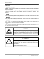
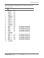
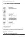
SIMADYN D
Digital Control System
User Manual
Processor module PM16
Edition 05.95
DK-Nr. 221441
User Manual, Processor module PM16
Edition
Edition status
1
Processor module PM16
03.91
2
Processor module PM16
05.95
Copying of this document and giving it to others and the use or
communication of the contents thereof is forbidden without express
authority. Offenders are liable to the payment of damages. All rights
are reserved in the event of the grant of a patent or the registration of
a utility model or design.
We have checked the contents of this Manual to ensure that they
coincide with the described hardware and software. However,
deviations cannot be completely ruled-out, so we cannot guarantee
complete conformance. However, the information in this document is
regularly checked and the necessary corrections included in
subsequent editions. We are thankful for any recommendations or
suggestions.
Contents
Contents
Warning information................................ ................................ ................................ .................... 1
1. Order Designation:................................ ................................ ................................ ..................3
2. Functional Description................................ ................................ ................................ .............3
3. Board Design ................................ ................................ ................................ .......................... 4
4. Application Notes ................................ ................................ ................................ .................... 5
5. Technical Specifications................................ ................................ ................................ ..........8
5.1. General Data ................................ ................................ ................................ ...........8
5.2. Electrical data ................................ ................................ ................................ ..........8
5.2.1. Power supply................................ ................................ ............................. 8
5.2.2. Binary inputs................................ ................................ .............................. 9
5.2.3. Binary outputs................................ ................................ ............................ 9
5.2.4. Serial Interfaces ................................ ................................ ........................ 9
6. Pin allocation of the PM16 ................................ ................................ ................................ ......10
6.1. Allocation of the serial interfaces X01, X02................................ .............................. 10
6.2. Pin allocation of the binary inputs and outputs, Connector X5................................ ..11
7. STRUC L-Mask for the PM16 board Master program................................ .............................. 12
8. Appendix................................ ................................ ................................ ................................ .13
8.1. Block diagram................................ ................................ ................................ ..........13
8.2. Scale drawing and connector table................................ ................................ ...........13
8.3. Arrangement drawing................................ ................................ ............................... 13
9. Miscellaneous ................................ ................................ ................................ ......................... 13
10. ECB instructions................................ ................................ ................................ .................... 14
Siemens AG Dk-Nr. 221441
SIMADYN D Hardware User Manual
Edition 05.95
Warning information
Edition 05.95
Siemens AG Dk-Nr. 221441
SIMADYN D Hardware User Manual
Warning information
NOTE!
The information in this Manual does not purport to cover all details or variations in equipment, nor to provide
for every possible contingency to be met in connection with installation, operation or maintenance.
Should further information be desired or should particular problems arise which are not covered sufficiently for
the purchaser’s purposes, please contact your local Siemens office.
Further, the contents of this Manual shall not become a part of or modify any prior or existing agreement,
committment or relationship. The sales contract contains the entire obligation of Siemens. The warranty
contained in the contract between the parties is the sole warranty of Siemens. Any statements contained
herein do not create new warranties nor modify the existing warranty.
Warning information
WARNING!
Electrical equipment has components which are at dangerous voltage levels.
If these instructions are not strictly adhered to, severe bodily injury and material
damage can result.
Only appropriately qualified personnel may work on this equipment or in its
vicinity.
This personnel must be completely knowledgeable about all the warnings and
service measures according to this User Manual.
The successful and safe operation of this equipment is dependent on proper
handling, installation, operation and maintenance.
Siemens AG Dk-Nr. 221441
SIMADYN D Hardware User Manual
Edition 05.95
1
Warning information
Definitions
*
QUALIFIED PERSONNEL
*
DANGER
*
WARNING
*
CAUTION
*
NOTE
For the purpose of this User Manual and product labels, a „Qualified person“ is someone who is familiar with the
installation, mounting, start-up and operation of the equipment and the hazards involved. He or she must have
the following qualifications:
1. Trained and authorized to energize, de-energize, clear, ground and tag circuits and equipment in accordance
with established safety procedures.
2. Trained in the proper care and use of protective equipment in accordance with established safety
procedures.
3. Trained in rendering first aid.
For the purpose of this User Manual and product labels, „Danger“ indicates death, severe personal injury and/or
substantial property damage will result if proper precautions are not taken.
For the purpose of this User Manual and product labels, „Warning“ indicates death, severe personal injury or
property damage can result if proper precautions are not taken.
For the purpose of this User Manual and product labels, „Caution“ indicates that minor personal injury or
material damage can result if proper precautions are not taken.
For the purpose of this User Manual, „Note“ indicates information about the product or the respective part of the
User Manual which is essential to highlight.
CAUTION!
This board contains components which can be destroyed by electrostatic
discharge. Prior to touching any electronics board, your body must be electrically
discharged. This can be simply done by touching a conductive, grounded object
immediately beforehand (e.g. bare metal cabinet components, socket protective
conductor contact).
WARNING!
Hazardous voltages are present in this electrical equipment during operation.
Non-observance of the safety instructions can result in severe personal injury or
property damage.
It is especially important that the warning information in all of the relevant
Operating Instructions are strictly observed.
2
Edition 05.95
Siemens AG Dk-Nr. 221441
SIMADYN D Hardware User Manual
Order Designation:
1. Order Designation:
6DD 1600 - 0AF0
Processor module PM16 with 128K RAM for software versions from 3.0 .
2. Functional Description
The processor module PM16 processes general technological control, calculation and regulation tasks
in the SIMADYN D system. These tasks lie above the drive level control and regulation functions
(torque shell). The board contains the -CMOS- 16 bit microprocessor 80C186 - 16MHz with
corresponding peripherals.
Plug-in program memory modules (MS31, MS3) are used in the mounting location X50 for the board
user programs as well as for the system firmware (operating system, supervisor program, function
module code, .... ). The user programs run on the processor under the SIMADYN D real time
operating system. This guarantees interrupt controlled fixed cycle times of ≥ 1ms, dependent upon
the configuration.
There are 16 binary input and 16 binary output channels available for the fast exchange of data with
the process IO (connector X5).The binary inputs can be declared, via software, as interrupt inputs. At
the occurrence of a signal edge at an interrupt input, the processor interrupts the current cyclic
processing and runs the function packet process interrupt job PIJ . Connection cables carrying binary
signals are connected to interface modules and not directly to the processor module.
The interface modules implement both the mechanical connection terminal and the electrical signal
adaptation. The plant signals can be directly connected to these terminals.
Two serial interfaces (connectors X01, X02) are available for communication :
- to a higher level computer
- for data transfers between SIMADYN D systems
- listing outputs to printers
- to the SIMADYN D system peripheral IO
(operator panel OP1, service unit US1 and programming unit PG 675, 685 or 750)
The seven segment display on the board front panel, indicates a "-" character during the start-up
phase and the configured processor number during normal operation. The display flashes with an
error code when a fault occurs.
The error codes are described in the processor module handling instructions /1/.
When an error message is displayed, the HEX supervisor can be activated by pressing the S1 key.
A forced board reset (Restart) can be initiated using the twin jack connectors X10 and X11 . The jack
connectors must therefore be jumpered by a switch or a shorting plug.
The 50 pin diagnostic connector X4 is available on the board for hardware diagnostics using a logic
analyzer or a recorder.
Three watchdogs are installed on each processor board to monitor the hardware and software system
states.
Siemens AG Dk-Nr. 221441
SIMADYN D Hardware User Manual
Edition 05.95
3
Board Design
The hardware monitor checks:
- Ready signal time-outs during system bus accessing
- Double address decoding errors
- Accessing unused or non-existent addresses
- Collision detection of a DMA access with a system bus access (Detection can be disabled by
software)
- System bus fault messages
The software monitor checks:
- Whether the processor is still running a cyclic task.
- Whether the interrupt controller for the serial interface, timer and inputs are fully operational.
A "Non-Maskable Interrupt" (NMI) is generated when the supervisor detects a fault. The processor
attempts to resolve the problem and resume cyclic operation. If the fault is caused by the processor
itself, then the processor switches to 'inactive', the red dot on the seven segment display is switched
on and the bus signal "system error" is activated.
3. Board Design
- Connectors for local and communication busses.
- CPU 80C186 - 16 MHz
- RAM
128 K Byte
Battery buffered by the power supply (PS)
- Connector terminal for the program memory sub-modules MS3/31/4/45
- 2 serial interfaces
selection of V24(RS232), 20mA(TTY), RS485
- 16 binary inputs
no galvanic isolation, used as interrupt controlled inputs
- 16 binary outputs
no galvanic isolation
maximum of 30V / 50mA
- Real time clock
resolution 10 ms; battery buffered by the PS
- 7 segment display for the configured processor number
or error display
- Board identification
4
Edition 05.95
Siemens AG Dk-Nr. 221441
SIMADYN D Hardware User Manual
Application Notes
- Hardware and software monitoring by watchdogs
- Test connector for a logic analyzer or recorder
4. Application Notes
The processor module PM16 can be installed in both the large racks such as SR1 and SR5 with local
and communication busses and the small racks such as SR2 and SR4 with local bus. It occupies two
standard slots in the racks.
The rack must either be installed with the bus terminator or a memory coupling board.
The board can be installed on any rack slot with "slot number coding", that contains the SIMADYN D
system bus interface. Whereby, it should be noted that the left-aligned slot must be installed with a
local bus master (processor module). If this is not adhered to, then the local peripheral boards will not
be supplied with the 8MHz clock. Daisy chain jumpers must be installed on empty slots for multiprocessor configurations.
The board must be fixed to the rack by screws (even during commissioning) to ensure correct
functioning.
If the board is connected to an adapter, then the frame must be shorted to the rack housing by a short
conductor.
The board may not be pulled or installed under power.
When the serial interfaces X01 and X02 are used, then thick film interface modules (hybrid modules)
must be installed. The following hybrid modules are currently available:
SS1 : 20 mA (TTY)
SS2 : V.24 (RS 232)
SS3 :
(RS 485)
The hybrid module for the serial interface X01 is to be installed on connector X51 (U1) and on
connector X52 (U2, see printed diagram) for the interface X02 .
ATTENTION: CHECK INSTALLATION LOCATION CAREFULLY!
The binary inputs and outputs are connected via interface modules, which are fixed to a terminal rail.
The connection from the board connector X5 to the interface modules is implemented with ribbon
cable.
Siemens AG Dk-Nr. 221441
SIMADYN D Hardware User Manual
Edition 05.95
5
Application Notes
The following connection configurations are possible:
a) All 16 binary inputs and outputs are brought from the PM16 connector X5 to the interface module
SE3.1 (24V no galvanic isolation) via a 40 pin ribbon cable.The external connection to the plant
are implemented there (screw terminals).
PM16
X5
16 Binär
in/outputs 24V
ribbon cable
40-way
40-way
Interface module
SE3.1
b) The 16 binary inputs and outputs are distributed to 4 different interface modules. A ribbon cable is
therefore connected to the PM16 board connector X5 with split connectors at the other end (4x10
pin) which are then brought out to the interface modules. It is then possible to connect e.g. 8 inputs
or outputs with galvanic isolation and 8 without galvanic isolation. The reference voltage of
M24/screen may be selected via the DIP-FIX switch S2 for the binary input signals. The default
setting is the reference voltage for M24 (s. 2GE 465 600 9005.01 AO).
PM16
X5
16 binary
in/outputs 24V
6
binary signals
40-way
10-way
10-way
10-way
10-way
10-way
10-way
10-way
10-way
Interface
module
Interface
module
Interface
module
Interface
module
Edition 05.95
Siemens AG Dk-Nr. 221441
SIMADYN D Hardware User Manual
Application Notes
Additional PM16 components:
a) Serial Interfaces
- Hybrid interface
SS1 (20 mA)
- Hybrid interface
SS2 ( V24 )
- Cable PM-SE12.1 : SC30.1 20 mA/ 2 m
6DD 1688-1AA0
6DD 1688-1AB0
6DD 1684-0DA1
- Cable PM-AS 512 : SC22.1 20 mA/ 10 m
- Cable PM-PG 675 : SC32 20 mA/ 10 m
- Cable PM-printer : SC34 20 mA/ 10 m
- Set of parts 25pin Cannon connector: SM3.1
- Hybrid interface
SS3 (RS485)
- Cable
: SC27 RS485/ 2,1 m
- SE 47.1 Bus connector module
6DD 1684-0CC1
6DD 1684-0DC0
6DD 1684-0DE0
6DD 1680-0AD0
6DD 1688-1AC0
6DD 1684-0CH0
6DD 1681-0EH0
b) Binary input cable
- 40pin
2,0 m SC18
6DD 1684-0BJ0
- 40pin --> 4+10pin
2,0 m SC13
6DD 1684-0BD0
c) Interface module
- SE3.1
6DD 1681-0AD0
16 Binary inputs and outputs, no galvanic isolation
- SE4.1
6DD 1681-0AE1
8 Binary inputs and outputs, no galvanic isolation
- SE5.3
6DD 1681-0AF3
8 Binary inputs maximum 220V galvanic isolation
- SE6.1
6DD 1681-0AG1
8 Binary outputs maximum 220V galvanic isolation
- SE37
8 Binary outputs 24V galvanic isolation
6DD 1681-0DH0
- SE41.1
8 Binary inputs 48V galvanic isolation
6DD 1681-0EB1
6DD 1681-0EB2
8 Binary inputs 24V galvanic isolation
Siemens AG Dk-Nr. 221441
SIMADYN D Hardware User Manual
Edition 05.95
7
Technical Specifications
5. Technical Specifications
5.1. General Data
INSULATION GROUP
AMBIENT TEMPERATURE
STORAGE TEMPERATURE
HUMIDITY CLASS
ALTITUDE RATING
MECHANICAL STRESS
PACKAGING SYSTEM
DIMENSIONS
BOARD WIDTH
WEIGHT
A FROM VDE 011 PARAGRAPH 13 GROUP 2 AT 24V-,15V,5V0 TO 55 DEG. C WITH FORCED VENTILATION
-40 TO +70 DEG. C
F ACCORDING TO DIN 40050
S ACCORDING TO DIN 40040
INSTALL IN FIXED EQUIPMENT, SENSITIVE TO VIBRATIONS
ES 902 C
233,4 * 220 MM
2 2/3 SEP = 2EB = 40.28 MM
0,7 KG
5.2. Electrical data
5.2.1. Power supply
VOLTAGE
VOLTAGE
VOLTAGE
VOLTAGE
VOLTAGE
+ 5V
+ 15 V
- 15 V
VCC
+ 3,4 V EXT
cross-connection
protection
no
no
no
no
yes
Fuse protection
no
no
no
no
no
DES
+ 5V
+ 15 V
- 15 V
VCC
+ 3,4 V EXT
MIN
TYPICAL MAX
UNIT
+ 4,75
+ 5,25 V
+ 14,40
+ 15,60 V
- 14,40
- 15,60 V
+ 2,20
+ 5,25 V
+ 2,20
+ 5,90 V
VOLTAGE
VOLTAGE
VOLTAGE
VOLTAGE
VOLTAGE
(+ 5 V)
(+ 15 V)
(- 15 V)
VCC
(+ 3,4 V EXT)
HARMONICS
HARMONICS
HARMONICS
HARMONICS
HARMONICS
(+ 5 V)
(+ 15 V)
(- 15 V)
VCC
(+ 3,4 V)
0,10
0,15
0,15
-----
Vpp
Vpp
Vpp
Vpp
Vpp
CURRENT
CURRENT
CURRENT
CURRENT
CURRENT
CURRENT
(+ 5 V) without modules
(+ 5 V) without module
(+ 15 V)
(- 15 V)
VCC (buffered)
(+ 3,4 V) (buffered)
1,30
1,40
0,05
0,05
0,80
1,15
A
A
A
A
mA
mA
POWER LOSS (+ 5 V) without modules
POWER LOSS (+ 15 V)
POWER LOSS (- 15 V)
VCC
(+ 3,4 V)
7,00
0,78
0,78
4,00
3,90
VA
VA
VA
mVA
mVA
8
Edition 05.95
Siemens AG Dk-Nr. 221441
SIMADYN D Hardware User Manual
Technical Specifications
5.2.2. Binary inputs
NUMBER
INPUT VOLTAGE
INPUT VOLTAGE
FOR 0 SIGNAL
FOR 1 SIGNAL
INPUT CURRENT
FOR 1 SIGNAL
RESPONSE TIME
RESPONSE TIME
16 NO GALVANIC ISOLATION
+ 24 V RATED VALUE
-1 V TO + 6 V ;OR BINARY INPUT OPEN
+ 13 V TO + 33V
TYP. 3 MA
220 uS with hybrid capacitor
20 uS without hybrid capacitor / Standard design
5.2.3. Binary outputs
NUMBER
16 NO GALVANIC ISOLATION!
POWER SUPPLY
P24 EXTERNAL SUPPLY
-RATED VALUE
24 V -HARMONICS
3.6 V -PERM. RANGE
+ 20 TO +30 V INCL. HARMONICS
-TEMPORARILY
+ 35 V SMALLER 0,5 SEC.
CURRENT COMSUMP.
P24 MAX. 900mA
OUTPUT CURRENT FOR 1 SIGNAL
-RATED VALUE
50 MA
-PERM. RANGE
0.2 MA TO 50 MA
SHORT CIRCUIT PROTECT ELECTRONIC
INDUCTIVE LIMITATION
TRIP VOLTAGE
AT V CC + 1 V
TOTAL LOADING
80 % FOR 50 DEG C ALL OUTPUTS 50 MA
RESIDUAL CURRENT
20 uA FOR O SIGNAL
SIGNAL LEVEL
-FOR 0 SIGNAL
MAX. 3 V
-FOR 1 SIGNAL
MIN. SUPPLY - 2.5 V
SWITCHING DELAY
15 uS
5.2.4. Serial Interfaces
NUMBER
DATA RATE
2
MAX. 19.2 KBd / SS1 (20 mA) / SS2 (V24)
MAX. 1.0 MBD / SS3 (RS485)
Siemens AG Dk-Nr. 221441
SIMADYN D Hardware User Manual
Edition 05.95
9
Pin allocation of the PM16
6. Pin allocation of the PM16
6.1. Allocation of the serial interfaces X01, X02
PIN
1
2
3
4
5
6
7
8
9
10
11
12
13
14
15
16
17
18
19
20
21
22
23
24
25
PIN
1
2
3
4
5
6
7
8
9
10
11
12
13
14
15
16
17
18
19
20
21
22
23
24
25
10
V24
FRAME GROUND
TRANSMIT DATA OUT
RECEIVE DATA IN
REQUEST TO SEND OUT
CLEAR TO SEND
DATA SET READY IN
GROUND
DATA CARRIER DETECT IN
GROUND
--+ 15 V
------RECEIVE/TRANSMIT CLOCK
--RECEIVE/TRANSMIT CLOCK
GROUND
--DATA TERMINAL READY OUT
--+5V
+5V
TRANSMIT RECEIVE CLOCK
- 15 V
T*D
R*D
*RTS
*CTS
*DCD
*RT*C
*TR*C
RS485
FRAME GROUND
REQUEST TO SEND
TRANSMIT/RECEIVE CLOCK
--TRANSMIT DATA OUT
RECEIVE/TRANSMIT CLOCK
DATA CARRIER DETECT
RECEIVE DATA IN
GROUND
--+ 15 V
----REQUEST TO SEND
TRANSMIT/RECEIVE CLOCK
--TRANSMIT DATA OUT
GROUND
RECEIVE/TRANSMIT CLOCK
DATA CARRIER DETECT
RECEIVE DATA IN
+5V
+5V
--- 15 V
20 MA (TTY)
FRAME GROUND
--------------GROUND
CURRENT LOOP + TRANSMIT
+ 15 V
20 MA SOURCE 1
CURRENT LOOP + RECEIVE
CURRENT LOOP - RECEIVE
--20 MA SOURCE 2
--GROUND
CURRENT LOOP - TRANSMIT
--20 MA DRAIN 1
+5V
+5V
20 MA DRAIN 2
- 15 V
+T*D
+R*D
-R*D
-T*D
+OUT 1,D
+IN 2,R
+OUT 2,D
+IN 3,R
+IN 4,R
+IN 1,R
-OUT 1,D
-IN 2,R
-OUT 2,D
-IN 3,R
-IN 4,R
-IN 1,R
Edition 05.95
Siemens AG Dk-Nr. 221441
SIMADYN D Hardware User Manual
Pin allocation of the PM16
6.2. Pin allocation of the binary inputs and outputs, Connector X5
Ribbon cable connector
PIN
DES.
1
2
3
4
5
6
7
8
9
10
11
12
13
14
15
16
17
18
19
20
21
22
23
24
25
26
27
28
29
30
31
32
33
34
35
36
37
38
39
40
OUTPUT 1
OUTPUT 2
OUTPUT 3
OUTPUT 4
OUTPUT 5
OUTPUT 6
OUTPUT 7
OUTPUT 8
P EXTERNAL
M EXTERNAL
OUTPUT 9
OUTPUT 10
OUTPUT 11
OUTPUT 12
OUTPUT 13
OUTPUT 14
OUTPUT 15
OUTPUT 16
P EXTERNAL
M EXTERNAL
INPUT 1
INPUT 2
INPUT 3
INPUT 4
INPUT 5
INPUT 6
INPUT 7
INPUT 8
P EXTERNAL
M EXTERNAL
INPUT 9
INPUT 10
INPUT 11
INPUT 12
INPUT 13
INPUT 14
INPUT 15
INPUT 16
P EXTERNAL
M EXTERNAL
CONNECTO
R
X5 A
X5 A
X5 A
X5 A
X5 A
X5 A
X5 A
X5 A
X5 A
X5 A
X5 B
X5 B
X5 B
X5 B
X5 B
X5 B
X5 B
X5 B
X5 B
X5 B
X5 C
X5 C
X5 C
X5 C
X5 C
X5 C
X5 C
X5 C
pos. INTERRUPT CONTROLLED
pos. INTERRUPT CONTROLLED
pos. INTERRUPT CONTROLLED
pos. INTERRUPT CONTROLLED
pos. INTERRUPT CONTROLLED
pos. INTERRUPT CONTROLLED
pos. INTERRUPT CONTROLLED
pos. INTERRUPT CONTROLLED
X5 D
X5 D
X5 D
X5 D
X5 D
X5 D
X5 D
X5 D
pos. INTERRUPT CONTROLLED
pos. INTERRUPT CONTROLLED
pos. INTERRUPT CONTROLLED
pos. INTERRUPT CONTROLLED
pos. INTERRUPT CONTROLLED
pos. INTERRUPT CONTROLLED
pos. INTERRUPT CONTROLLED
pos. INTERRUPT CONTROLLED
Siemens AG Dk-Nr. 221441
SIMADYN D Hardware User Manual
Edition 05.95
11
STRUC L-Mask for the PM16 board Master program
7. STRUC L-Mask for the PM16 board Master program
(see Master program description)
STRUC-L MASK
: PM16
PIJ 1N = 0
SFJ 1N = 0
PRX 1N = 0
PJ1 1N = ?
PJ2 1N = 0
PJ3 1N = 0
PJ4 1N = 0
PJ5 1N = 0
PJ6 1N = 0
PJ7 1N = 0
PJ8 1N = 0
PTX 1N = 0
ILS IK = 0
ICS IK = 0
TO TG = ?
T1 TS = ?
T2 TS = ?
T3 TS = ?
T4 TS = ?
T5 TS = ?
TY TX = T?
SSM 2C = 0
ISE 1C = N
CCT 8R = 0
CCR 8R = 0
COP 8R = 0
CMS 8N = 0
CTS 8N = 0
MS 2M = 0
X01 1M = 0
X02 1M = 0
X5C 8K <
X5D 8K <
X5A 8K >
X5B 8K >
^"processor module 1 standard, L+C-bus^"
^"alarm processing FP^"
^"system error FP^"
^"special communication FP receive^"
^"1. permanent processing FP^"
^"special communication FP transmit^"
^"L-Bus-Interrupt transmit^"
^"C-Bus-Interrupt transmit^"
^"basic sampling time^"
^"1. s.t.*T0,produced LB- and CB-conn.^"
^"2. s.t.
^"
^"
^"3. s.t.
^"
^"
^"4. s.t.
^"
^"
^"5. s.t.
^"
^"
^"sampling time of system FP^"
^"Length SAVE-area, (n*1+2) kByte^"
^"Ignore syst. except. (RDYINT) (Y/N) ?^"
^"transmitter communication names.Tx^"
^"receiver communication names.Tx^"
^"service communication names.Tx^"
^"message system names^"
^"comm. transport system names^"
^"message systems^"
^"1. serial interface^"
^"2. serial interface^"
^"binary inp. 1, interrupt ctr.^"
^"binary inp. 2, interrupt ctr.^"
^"binary outputs 1^"
^"binary outputs 2^"
The PM16 requires 3 Sub-modules :
- 1 * PROGRAM MEMORY
- 2 * SERIAL INTERFACES
The X5 connector, binary input and output, can be accessed by the following function modules:
CONN. SECTION
X5C -|--|- BII8
X5D -| |- BID8
12
FUNCTION MODULE
Binary input (8 Binary valu&es)
Binary input (8 Binary valu&es, normal mode)
Edition 05.95
Siemens AG Dk-Nr. 221441
SIMADYN D Hardware User Manual
Appendix
|- SBI
Numerical input, Byte
X5A -|--|- BIQ8
Binary output (8 Binary valu&es)
X5B -| |- BQD8
Binary output (8 Binary valu&es, normal mode)
|- SBQ
Numerical output, Byte
8. Appendix
8.1. Block diagram
Block diagram
3GE.465 600.9005.01 SU
8.2. Scale drawing and connector table
Scale drawing with front panel view and table of
the utilized connectors
3GE.465 600.9005.00 MB
8.3. Arrangement drawing
Arrangement drawing
3GE.465 600.9005.02 AO
9. Miscellaneous
Siemens AG Dk-Nr. 221441
SIMADYN D Hardware User Manual
Edition 05.95
13
ECB instructions
10. ECB instructions
Components which can be destroyed by electrostatic discharge (ECB)
Generally, electronic boards should only be touched when absolutely necessary.
The human body must be electrically discharged before touching an electronic board. This can be
simply done by touching a conductive, grounded object directly beforehand (e.g. bare metal cubicle
components, socket outlet protective conductor contact.
Boards must not come into contact with highly-insulating materials - e.g. plastic foils, insulated
desktops, articles of clothing manufactured from man-made fibers.
Boards must only be placed on conductive surfaces.
When soldering, the soldering iron tip must be grounded.
Boards and components should only be stored and transported in conductive packaging (e.g.
metalized plastic boxes, metal containers).
If the packing material is not conductive, the boards must be wrapped with a conductive packing
material, e.g. conductive foam rubber or household aluminum foil.
The necessary ECB protective measures are clearly shown in the following diagram.
a = Conductive floor surface
b = ECB table
c = ECB shoes
Seated
14
d = ECB overall
e = ECB chain
f = Cubicle ground connection
Standing
Edition 05.95
Standing/sitting
Siemens AG Dk-Nr. 221441
SIMADYN D Hardware User Manual
ECB instructions
Siemens AG Dk-Nr. 221441
SIMADYN D Hardware User Manual
Edition 05.95
15
ECB instructions
Drives and Standard Products
Motors and Drives Systems Group
Postfach 3269, D-91050 Erlangen
16
System-Based
Technology
Edition 05.95
Siemens AG Dk-Nr. 221441
SIMADYN D Hardware User Manual