1
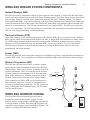
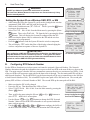
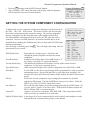
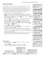
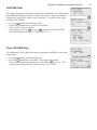
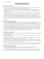
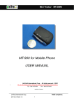
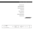
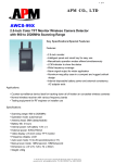
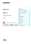
R
INSTALLATION AND OPERATION INSTRUCTIONS
Wireless Programmer
for Wireless Sensor System
FOR PLATINUM CONTROLS WITH COMMUNICATION
Wireless
Programmer
>Config devices
Get device data
WP.Setup Mode
Auto Mode
For Heat-Timer-Wireless Sensor System Only
Connect to other
Wireless units
LED
Green = in operation
Red = charging
Mode Button
Power
Switch
0
1
2
3
4
5
6
7
8
9
A
B
C
D
E
F
Mode
Accept/Enter Button
� ▲ ▼
This equipment has been tested and found to comply with
the limits for a class B digital device, pursuant to part 15
of the FCC Rules. These limits are designed to provide
reasonable protection against harmful interference in a
residential installation. This equipment generates, uses
and can radiate radio frequency energy and if not installed
and used in accordance with the instructions, may cause
harmful interference to radio communications. However,
there is no guarantee that interference will not occur in
a particular installation. If this equipment does cause
harmful interference to radio or television reception, which
can be determined by turning the equipment off and on, the
user is encouraged to try to correct the interference by one
or more of the following measures:
• Reorient or relocate the receiving antenna.
• Increase separation between the equipment and wireless
Components.
• Connect the equipment into an outlet on a circuit
different from that to which the wireless components are
connected.
• Consult the dealer or an experienced radio/TV
technician for help.
WARNING
Charger connection
Load Button
This equipment has been certified to comply with
the limits for a class B computing device, pursuant
to FCC Rules. In order to maintain compliance
with FCC regulation, the antenna(s) used for this
transmitter must be installed to provide a separation
of at least 8" from all persons and must not be
collocated or operating in conjunction with any other
antenna or transmitter. The user is cautioned that
changes or modifications made to the equipment
without the approval of the manufacturer could void
the user’s authority to operate this equipment.
2
Heat-Timer Corp.
Table of Contents
PRODUCT CONCEPT . . . . . . . . . . . . . . . . . 2
Wireless Sensor System Components . . . . . . . .
Network Manager (NM) . . . . . . . . . . . . . . .
Transceiver/Router (RTR) . . . . . . . . . . . . . .
Sensor (SNR) . . . . . . . . . . . . . . . . . . . .
Wireless Programmer (WP) . . . . . . . . . . . . .
Wireless Address Coding . . . . . . . . . . . . . . .
RF Mapping (Survey) . . . . . . . . . . . . . . . . .
Wireless Programmer (WP) Emulation and Antennas .
Setting the System ID . . . . . . . . . . . . . . . .
Emulating a Network Manager (NM) . . . . . . . .
Emulating a Transceiver/Router (RTR) . . . . . . .
Emulating a Sensor (SNR) . . . . . . . . . . . . .
.
.
.
.
.
.
.
.
.
.
.
.
.
.
.
.
.
.
.
.
.
.
.
.
.3
.3
.3
.3
.3
.3
.4
.5
.5
.5
.6
.6
Configuring the System Components . . . . . . . . . . .
A.Configure System ID . . . . . . . . . . . . . . . . .
Entering the System ID in the WP. . . . . . . . . . . .
Entering the System ID in the WP. . . . . . . . . . . .
Setting the System ID on a Wireless SNR, RTR, or NM
B.Configuring RTR Network Number . . . . . . . . . .
Getting the System Component Configuration . . . . . .
DETECT RSSI Mode . . . . . . . . . . . . . . . . . .
SNIFF Mode . . . . . . . . . . . . . . . . . . . . . . .
CAPTURE Data . . . . . . . . . . . . . . . . . . . . .
Clear CAPTURE Data . . . . . . . . . . . . . . . . . .
.7
.7
.7
.8
.8
.8
.9
11
12
13
13
TROUBLESHOOT . . . . . . . . . . . . . . . . . . . 14
PRODUCT CONCEPT
The Heat-Timer Wireless Network Sensor System is designed to be utilized in a variety of large buildings,
garden apartments, and in retrofit applications, giving both the accuracy and flexibility required to heat those
buildings. The Heat-Timer Wireless Network Sensor System is designed to ease the installation of space
sensors in buildings were it would be difficult or cost prohibitive utilizing other means. Thus, allowing HeatTimer Platinum controls with communication the access to the wireless sensor data. The values read from the
wireless system is used by the Platinum controls to fine-tune its operation. Furthermore, the Platinum controls
can be configured to log this information using the proper communication package.
The primary integral components of the system are: the Network Manager (NM), the Transceivers/Routers (RTR),
the Wireless Sensors (SNR), and finally, the Wireless Programmer (WP). The SNRs communicate their information
to a nearby RTR or NM. The RTRs trickle down the information down either to another RTR or to the NM. The WP
is a tool that is used to map, configure, diagnose, and troubleshoot the Heat-Timer Wireless Network System.
The NM is connected to the Heat-Timer Platinum control using a cabled RS485 connection. The SNRs communicate
their information to the RTRs and the NM. The RTRs will pass down the information to other RTRs until finally
all the information is passed down to the NM. The NM will transmit the data using RS485 connection to the
Platinum control. The control will process the data and pass it to the Internet to Heat-Timer servers or thru Visual
Gold Plus to a computer. An Internet Control Management System (ICMS) client can access this information by
logging to their web account.
Security
Each Wireless Sensor Network System will have a unique ID that prevents it from getting access to other wireless
systems as well as prevent other systems from accessing it. That means, a NM, RTR, or SNR can only listen to
and transmit to another component on the same unique network. Each of the wireless system components must
be configured to the specific network for it to communicate.
Improved Penetration and Extended Range.
The HT-Wireless Network Sensor System utilizes the 900MHz frequency range for better penetration. The
Frequency Hopping Spread Spectrum has been used to improve performance and range. This allows the system
to be installed not just in high-rise buildings, but also in garden apartments, campus type environment, etc. For
applications where long ranges between components is required, the utilization of RTRs with External High
Gain Antennas will help reduce the number of intermediate RTRs
Wireless Programmer Operation Manual
3
WIRELESS SENSOR SYSTEM COMPONENTS
Network Manager (NM)
The NM is the primary component in the Heat-Timer Wireless Sensor System. It collects the data from all the
sensors and routers and passes it on to the Heat-Timer Platinum control. Each Heat-Timer wireless network has
only one NM. However, one NM can be connected to multiple Heat-Timer Platinum controls. The NM can
listen to RTRs and SNRs. It is connected directly to the Heat-Timer Platinum control using a RS485 connection
to the RI board on the back of the control. The NM has an External High Gain Antenna with an extended cable
that can be mounted remotely. The NM can communicate to two upstream RTRs. The NM is powered using
a 5 to 8 VAC transformer. The WP can provide power to the NM when connected to it using the RS485 phone
cable for surveying programming, and troubleshooting.
Transceiver/Router (RTR)
When SNR locations are not within reception range of the NM, the RTR can act as a range extender. Multiple
RTRs can pass on the information from the SNRs to the NM. A Single RTR can communicate to many sensors.
Two RTRs with an External High Gain Antennas can be used to extended the transmission range over large
distances. A RTR can communicate to two upstream RTRs. It is powered using a 5 to 8 VAC transformer.
The WP can provide power to the RTR when connected to it using the RS485 phone cable for surveying
programming, and troubleshooting.
Sensor (SNR)
The SNR measures the space temperature and passes it in addition to its battery status and other information to
a nearby RTR or NM. It is powered by two AA batteries (different SNRs require different AA battery voltage).
Wireless Programmer (WP)
WIRELESS ADDRESS CODING
The Heat-Timer Wireless Network Sensor System is
designed for extension and growth. A single wireless
network can have a large number of RTRs that communicate
to a larger number of SNRs. Each NM or RTR (Parent) can
communicate directly to two upstream RTRs (Children). The
diagram is a sample RTR addressing structure.
R9
R10
R7
R8
R7B
R7A
R5
R3B
R3A
Rtr Even Path
Sub- Path
Rtr Odd Path
The WP is the tool used to map/survey, configure, emulate,
power, diagnose, and troubleshoot the Heat-Timer Wireless
Sensor System. In the survey process, it emulates each of the
wireless components. Later, it is needed to set the Wireless
Network parameters and configure each of the components
based on the initial survey. It can be connected to each of
the Heat-Timer Wireless Network System using a RS485.
When connected to a NM or RTR, it will provide power to
that component. Moreover, it is used as a diagnostic tool,
by listening and analyzing system data. The WP is powered
using a rechargeable Ni-Cd internal battery. The WP comes
with an external charger.
R6
R4B
R3
R4
R1
R2
R4A
Key
RTR
00
Network Manager
NM
4
Heat-Timer Corp.
INSTALLATION
Building Cutaway
Prior to purchasing the wireless components, an RF Mapping survey must
be done. After the survey, the NM, RTRs, and SNRs can be programmed
and installed at the locations assigned using the survey followed by
connecting the NM to the Platinum control. Finally, configure each of the
wireless components (SNRs) using the communication interface (Visual
Gold Plus or the Internet) for the Platinum control. Remember that NM
and RTRs can only be configured on the Internet. That is after the physical
installation of the wireless components, log on to the Internet or Visual
Gold Plus to the Heat-Timer Platinum control to configure the individual
wireless components to work with the Heat-Timer control.
P4=SNR
Low Gain Antenna
P3=RTR3
The goal is to assign the wireless components to the locations which
best meets building, user, power source, and best transmission criteria.
The survey involves the use of two WPs. Each of the WPs will be set
to emulate a different component of the Heat-Timer Wireless Network
System. Then, test communication between the different components.
You must set both WPs to the same System ID#.
C
WP1
=
NM
WP2
=
RTR
B
P2=RTR1
RF MAPPING (SURVEY)
WP2
=
SNR
WP1
=
NM
WP2
=
RTR
A
P1=NM
High Gain Antenna
Plat Control
WP1
=
NM
(A Survey) Assign the NM & First RTR locations:
• Initially, setup the first WP1 to emulate a NM and the second to emulate a RTR. Since the NM will have a
high gain antenna, connect a high gain antenna (Long Antenna) to the WP1 (emulating the NM). Place the
first WP1 (emulating the NM) where it can be connected to the Heat-Timer Platinum control, normally within
the boiler room. Make sure that a power source is available to power the NM.
• Place the second WP2 (emulating the first RTR) in one of the floors above where it can communicate with the
WP1. Again, make sure that the locations selected have a power source where the RTR transformer can be
connected to.
• Test the signal strength between the two WPs. The signal strength reading (RSSI) should be above 650 for a
reliable connection. Upon having good communication MARK the two locations of the WPs. Mark the WP1
(emulating the NM) with P1 (Position 1)=NM and WP2 (emulating RTR) with P2 (Position 2)=RTR1. If a
good signal strength cannot be achieved try replacing the WP2 Low-Gain antenna (Short Antenna) with a
High-Gain antenna (Long Antenna). If that was successful, you'll need to assign an External RTR with the
High-gain antenna to that location.
(B Survey) Assign the Second RTR location:
• Now, move the WP1 (NM) from the boiler to the location of the WP2 (RTR)=P2. If in the (A Survey) WP2
had a low gain antenna, make sure that in the (B Survey) WP1 has a low gain antenna as well.
• Then move the second WP2 (RTR) to emulate the second upstream router and repeat the process. Mark the
WP2 (emulating the second RTR) with P3=RTR3. For the wireless network to function, it requires the presence
of a NM with the same System ID as the wireless network. Thus, keeping one of the WPs set as a NM will
maintain the accessibility of the wireless network.
IMPORTANT
• When the WP is emulating a NM or an External RTR , the High Gain Antenna (Long Antenna) must be used
for accurate reception strength.
Wireless Programmer Operation Manual
5
IMPORTANT
• A NM or a RTR (Parent) can communicate to ONLY TWO upstream RTRs (Children). It is important for the
installer to map the location based on this concept.
• When placing multiple wireless components, make sure there is at least six feet of spacing between any
two antennas or an antenna and a high voltage power line to reduce frequency noise.
(C Survey) Assign the SNR location:
• Now, move the WP1 (NM) from the P2 location to the WP2 (RTR)=P3. If in the (B Survey) WP2 had a low
gain antenna, make sure that in the (C Survey) WP1 has a low gain antenna as well.
• Then, program the second WP2 to emulate a SNR. Make sure that WP2 (SNR) has a low gain antenna. Place
the WP2 on an inside wall five to six feet off the floor in the room that represents the actual space temperature
away from windows, heaters, vents, and shelves or objects that may impeded the air flow. It should not be
mounted in bathrooms, kitchens, or closets.
WIRELESS PROGRAMMER (WP) EMULATION AND ANTENNAS
To perform a building mapping/survey, the WP must be set to emulate the different Heat-Timer Wireless
Network components. The WP comes with two different antennas a short (low gain) and a long (high gain).
The short antenna (low gain) should be connected to the WP when it is emulating a SNR or a standard RTR
with an internal antenna. The long antenna (high gain) should be used when the WP is emulating a NM or a
RTR with an External High Gain Antenna (long range applications). That will give the surveyor the capability
of testing transmission and reception signal strength as well as assign locations to the different wireless
components. To set the WP to emulate each component, follow the component emulation process. Before
starting the process, The System ID must be set.
Setting the System ID
•
•
•
•
•
Make sure that the WP is fully charged.
Power the WP on. That should turn the LED to Green.
Select WP.Setup Mode from the Main menu by pressing the (Enter /
◄┘ ) button. Then, type a System ID or press the (Down / ▼ ) button to
select a random Id. To accept the new System ID press the (Enter / ◄┘ )
button. Then, press the F button to load it into the WP.
This will be followed by the Emulation Mode.
Remember to record the System ID to help you in setting up the next WP to
the same System ID.
WARNING
DO NOT use 0000 as a System ID to avoid errors in operation.
The Heat-Timer Wireless Network components can communicate only if they
have the same System ID.
-WP.SETUP mode
SYSTEM ID# C9E5
[UP] delete
[DWN] pick
◄┘
*CONFIG. MODE[9]
WP.Sys Id# C9E5
[F] to load
F
-WP.Setup mode
> Emulate RTR
Emulate SNR
Emulate NM
Emulating a Network Manager (NM)
•
•
•
After setting the System ID on the WP, the Emulation menu will display.
Select EMULATE NM and Press the ◄┘ followed by the F to proceed
with the NM Emulation. An ACK (Acknowledge) will appear on the third
line of the display acknowledging the acceptance by the WP.
Press the Mode to enter the SURVEY MODE, which appears on the top of
the display. The second display line will read NET MANAGER.
◄┘
-WP.Setup mode
EMULATE NM
[F] to load
F
-WP.Setup mode
Setup complete
[Mode] to exit
6
Heat-Timer Corp.
Exit NM Emulation:
• To exit this mode, press the
Mode
-WP.SETUP mode
SYSTEM ID# C9E5
[UP] delete
[DWN] pick
Mode
Mode
to go back to the System ID# Setup.
SURVEY MODE
NET MANAGER
IMPORTANT
To exit the NM Survey Mode the user MUST
Select to Emulate a RTR or a SNR first.
Emulating a Transceiver/Router (RTR)
•
•
•
•
•
•
•
•
•
After setting the System ID on the WP, the Emulation menu will display.
Select EMULATE RTR and Press the ◄┘ . The option for the
transmission power will follow.
A RTR will default to 100mw transmission power. Do not change this value.
Press the F to accept transmission power and proceed to the Sniff/Detect
RSSI menu.
Select DETECT RSSI using the ◄┘ button followed by the F to
accept.
Press the Mode to go to the main menu.
Select Auto Mode using the ▼ or ▲ buttons. Then press the ◄┘
button to accept. Within a few seconds, data should start to show on the
display.
The Numbers below the MASTER and WPROG represents the signal
strength received by each of the components from the other component. That
is, the number below MASTER represents how well the MASTER was
received by the WPROG.
The fourth line data contains R01 which represents the master's ID. A 00
represents the NM. Any ID that starts with the R represents a RTR.
The NEW 01A represents the next RTR ID upstream available.
Mode
*AUTO MODE
Clr capture
Yes
data
>No
Mode
•
•
-WP.Setup mode
SNIFF
> DETECT RSSI
Accept Detect RSSI
◄┘
-WP.Setup mode
DETECT RSSI
[F] to load
Enter the Detect RSSI F
Config devices
Get device data
WP.Setup Mode
> Auto Mode
Enter Auto Mode
◄┘
[1]
Mode
◄┘
Config devices
Get device data
WP.Setup Mode
> Auto Mode
Emulating a Sensor (SNR)
•
•
•
Accept 100mw F
AUTO MODE
MASTER
WPROG
65
62
R01
NEW 01A
Exit RTR Emulation:
• To exit this mode, press the Mode . The Clear capture data
option will show.
• Pressing the Mode again will direct you to the AUTO MENU.
AUTO MENU
Auto Mode
Capture
RTR TABLE
SNR TABLE
> Exit Auto
-WP.Setup mode
EMULATE RTR
>100mw
200mw
[F] to load
After setting the System ID on the WP, the Emulation menu will display.
Select EMULATE SNR and Press the ◄┘ .
Select from the Detect RSSI/Sniff menu DETECT RSSI using the
button followed by the F to accept.
Press the Mode to go to the main menu.
Select Auto Mode using the ▼ or ▲ buttons. Then, press the
button to accept. Within a few seconds, data should start to display.
◄┘
◄┘
-WP.Setup mode
EMULATE SNR
[F] to load
Accept Emulate SNR F
-WP.Setup mode
SNIFF
> DETECT RSSI
•
•
Wireless Programmer Operation Manual
7
The Numbers below the MASTER and WPROG represents the signal
Accept Detect RSSI ◄┘
strength received of each of the components from the other component. That
-WP.Setup mode
is, the number below MASTER represents how strong the MASTER was
DETECT RSSI
heard by the WPROG.
[F] to load
The fourth line data contains 00 which represents the master's ID. A 00
Enter the Detect RSSI F
represents the NM. Any ID that starts with the R represents a RTR.
Exit SNR Emulation:
• To exit this mode, press the Mode . The Clear capture data
option will show.
• Pressing the Mode again will direct you to the AUTO MENU.
• Select Exit Auto Mode to go back to the main menu.
Mode
*AUTO MODE
Clr capture
Yes
data
>No
Mode
AUTO MENU
Auto Mode
Capture
RTR TABLE
SNR TABLE
> Exit Auto
Config devices
Get device data
WP.Setup Mode
> Auto Mode
To enter Auto Mode
AUTO MODE
MASTER
63
00
◄┘
WPROG
51
[1]
Mode
◄┘
Config devices
Get device data
WP.Setup Mode
> Auto Mode
CONFIGURING THE SYSTEM COMPONENTS
For the Heat-Timer Wireless Network Sensor System to function, a NM with a System ID must be activated.
The WP is the only way any of the wireless components can be configured. For a new installation, start by
configuring the NM. Then, configure the RTRs followed by the SNRs.
A.
Configure System ID
Each wireless network should have a unique System ID. The System ID enables all wireless components
with that ID to communicate to each other. The WP is the only tool used to configure all system components
and their parameters. Connect the WP using the phone cable to the wireless component to be configured with
the System ID. The WP will power the NM or RTR if no power source was connected to them. However, a
SNR must have its batteries connected and operational and the SNR in Install mode (by pressing and holding
the SNR Install button). Then, configure the WP with the System ID to be used on the Heat-Timer Wireless
Network Sensor System.
Entering the System ID in the WP
•
•
•
•
Make sure that the WP is fully charged.
Power the WP on. That should turn the LED to Green.
Select WP.Setup Mode from the Main menu by pressing the (Enter
/ ◄┘ ) button. Then, type a System ID or press the (Down / ▼ ) button to
select a random Id. To accept the new System ID press the (Enter / ◄┘ )
button. Then, press the F button to load it into the WP.
This will be followed by the Emulation Mode menu.
-WP.SETUP mode
SYSTEM ID# C9E5
[UP] delete
[DWN] pick
Accept the System ID
◄┘
*CONFIG. MODE[9]
WP.Sys Id# C9E5
[F] to load
8
Heat-Timer Corp.
WARNING
DO NOT use 0000 as a System ID to avoid errors in operation.
The Heat-Timer Wireless Network components can communicate only if they
have the same System ID.
Setting the System ID on a Wireless SNR, RTR, or NM
•
Load the System ID F
-WP.Setup mode
> Emulate RTR
Emulate SNR
Emulate NM
Exit to Main Menu
Mode
After setting the WP to the System ID, you'll need to configure the wireless
> Config devices
components; SNR, RTR, and NM, with the System ID.
Get device data
When in the Emulation menu ( WP.Setup Mode ) press the Mode button
WP.Setup Mode
Auto Mode
to return to the main menu.
Select Config devices from the Main menu by pressing the (Enter /
Accept Config Devices ◄┘
◄┘ ) button. Then, select System
Id from the list by pressing the (Enter
*CONFIG. MODE[9]
/ ◄┘ ) button. This will display the System ID configured into the WP.
> System Id
Make sure that the phone cable is connected to the WP and the wireless
Reset Sensor
component to be programmed.
PWER dwn SNR
Press the F button to load the System ID into the wireless component.
Select System ID ◄┘
This will display ACK on the third line of the display acknowledging the
wireless component acceptance of the new System ID.
*CONFIG. MODE[9]
•
•
•
•
•
IMPORTANT
After configuring a SNR with the System ID for the first time, the SNR will go to
Sleep/Normal Mode until the next wake up interval. To bring back the SNR to
the Install mode, the user must press and hold down the SNR button for three
seconds or until the SNR PCB LED light starts blinking.
B.
WP.Sys Id# C9E5
[F] to load
To load the System ID F
Configuring RTR Network Number
For the RTRs to function in a wireless system, each must be assigned a Network Number. The Network
Number determines the path the information uses to pass on from one RTR to the next all the way down to the
NM. The main concept is that the NM can communicate upstream directly to a maximum of two RTRs. Each
of the two RTRs will represent a main path for the data to travel through. The first main path RTRs will have
odd Network Numbers. The first RTR (R01) on the first main path will be set to communicate to the NM (has
a fixed Network Number of 00). The second RTR up the same path will be R03 and so on. The second path
primary RTR will have a Network Number of R02. The second RTR up the same path will be R04.
•
•
•
Make sure that the WP is fully charged.
Power the WP on. That should turn the LED to Green.
Select Configure devices from the Main menu by pressing the
(Enter / ◄┘ ) button.
•
Then, scroll in the menu using the (Down / ▼ ) or (Up / ▲ ) buttons to
select RTR address menu option.
Use the (Down / ▼ ) or (Up / ▲ ) buttons to change the RTR Network
Number. Make sure the RTR Network number is not repeated within the
same wireless network.
Use the 0 , A , B , C , D , or E buttons configure the Suffix of
the RTR Network Number. The Suffix will determine the RTR sub-path.
•
•
> Config devices
Get device data
WP.Setup Mode
Auto Mode
Accept Config Devices
Scroll to RTR Address
◄┘
▲
or
▼
*CONFIG. MODE[4]
Wake up Period
RF out
> RTR address
Wireless Programmer Operation Manual
•
•
Press the F button to load the RTR Network Number.
This will display ACK on the third line of the display acknowledging the
RTR acceptance of the new Network Number.
To select RTR address
9
◄┘
*CONFIG. MODE[4]
RTR NET#01 0
USE up & dwn
FOR SUFFIX[0AB]
GETTING THE SYSTEM COMPONENT CONFIGURATION
To find out the wireless component configuration parameters, the WP must be in
the Get device data menu. This menu will allow the WP to display
the wireless component specific parameter settings. The wireless component
must be connected to the WP using the phone cable supplied with the WP.
The NM and RTRs can temporarily be powered by the WP when the cable is
connected. However, the SNR must have its batteries installed and be in the
Install Mode (by holding the SNR button for three seconds until PCB LED starts
blinking continuously).
After selecting each setting, press the F . This will display the setting value for
approximately two seconds.
RSSI (Read Only):
Config devices
> Get device data
WP.Setup Mode
Auto Mode
◄┘
*GET MODE [11]
> Get RSSI
Get Volt
Get Version
Get Type
Get H.Beat
Get RF out
Get NET ADD#
Get System Id
Get Module Id
Represents the reception power. It indicates the
strength the parent component can hear the current
component.
Volt (Read Only):
It indicates the Voltage status of the SNR batteries. If
the Voltage is less than 3.0, replace the batteries.
Version (Read Only):
Will indicate the Hardware and Software versions of the current wireless
component. Useful when contacting factory.
Type (Read Only):
When selected will display if the wireless component was a NM, RTR, or SNR.
Heart Beat:
For the SNR, it is the interval at which the SNR is programmed to wake up and start
transmitting its data. For the NM and RTRs, it is the interval at which they will
transmit their status (RTR Network Number, RSSI, Module ID, and RF Out) to their
parent.
RF Out:
Each of the wireless components is pre-configured to transmit at a specified
appropriate RF strength. The NM and RTRs are factory set to 100mw. While the
SNR is set to 25mw. DO NOT change these values.
Net Address #:
This is the Network Number of wireless component displayed in HEX format. See
Network Address Number Translation Table. SNR Network Numbers indicate the
RTR or NM the SNR is communicating to.
System ID:
Applies to all wireless components; NM, RTR, SNR. Only components with the
same System ID can communicate to each other.
Module ID (Read Only): Is the unique ID of each component that is used to identify and configure it on the
Platinum Remote communication package, or the Internet.
10
Heat-Timer Corp.
NETWORK ADDRESS NUMBER TRANSLATION
MAIN PATH
NETWORK
RTR
ADD#
NM
0180-0000
RTR ODD PATH
Router 1
0280-0000
Router 3
0380-0000
Router 5
0480-0000
Router 7
0580-0000
Router 9
0680-0000
0780-0000
Router 11
Router 13
0880-0000
Router 15
0980-0000
Router 17
0A80-0000
Router 19
0B80-0000
RTR EVEN PATH
Router 2
02C0-0000
Router 4
03C0-0000
Router 6
04C0-0000
Router 8
05C0-0000
Router 10
06C0-0000
Router 12
07C0-0000
Router 14
08C0-0000
Router 16
09C0-0000
Router 18
0AC0-0000
Router 20
0BC0-0000
SUB-PATH
RTR
NETWORK
ADD#
SUB-PATH A
SUB-PATH
RTR
NETWORK
ADD#
SUB-PATH B
Router 1A
Router 3A
Router 5A
Router 7A
Router 9A
Router 11A
Router 13A
Router 15A
Router 17A
Router 19A
03A0-0000
0490-0000
0588-0000
0684-0000
0782-0000
0881-0000
0980-8000
0A80-4000
0B80-2000
0C80-1000
Router 1B
Router 3B
Router 5B
Router 7B
Router 9B
Router 11B
Router 13B
Router 15B
Router 17B
Router 19B
04A0-0000
0590-0000
0688-0000
0784-0000
0882-0000
0981-0000
0A80-8000
0B80-4000
0C80-2000
0D80-1000
Router 2A
Router 4A
Router 6A
Router 8A
Router 10A
Router 12A
Router 14A
Router 16A
Router 18A
Router 20A
03E4-0000
04D0-0000
05C8-0000
06C4-0000
07C2-0000
08C3-0000
09C0-8000
0AC0-4000
0BC0-2000
0CC0-1000
Router 2B
Router 4B
Router 6B
Router 8B
Router 10B
Router 12B
Router 14B
Router 16B
Router 18B
Router 20B
04E4-0000
05D0-0000
06C8-0000
07C4-0000
08C2-0000
09C3-0000
0AC0-8000
0BC0-4000
0CC0-2000
0DC0-1000
Wireless Programmer Operation Manual
DETECT RSSI Mode
Detecting RSSI is available only when the WP is emulating a RTR or a SNR.
It allows the WP to show the loudest wireless transmitters within a specific
Network (have the same System ID) within an area at any point in time. Thus,
it will not show all wireless transmitters. It is primarily used in mapping a
new wireless network, adding wireless components to an existing one, or in
troubleshooting a wireless component transmission or reception.
• Power the WP on. That should turn the LED to Green.
• Select WP.Setup Mode from the Main menu by pressing the (Enter /
◄┘ ) button. Then, type the System ID of the existing wireless network. To
accept the new System ID press the (Enter / ◄┘ ) button. Then, press the F
button to load it into the WP.
• Select EMULATE RTR or EMULATE SNR from the Emulation menu
and Press the ◄┘ . The option for the transmission power will follow.
• If emulating a RTR, the transmission power screen will display. Select
100mw transmission power. Press the F to accept transmission power.
• Select DETECT RSSI from the Sniff/Detect RSSI menu using the ◄┘
button followed by the F to accept.
• Press the Mode to go back to the main menu.
• Select Auto Mode then press the ◄┘ button to accept. Within a few
seconds, data should start to display.
• The Numbers below the MASTER and WPROG represents the signal
strength received of each of the components from the other component. That
is, the number below MASTER represents the strength the MASTER signal
was received by the WPROG.
• The fourth line data contains R01 which represents the master's ID. A 00
represents the NM. Any ID that starts with the R represents a RTR.
11
-WP.SETUP mode
SYSTEM ID# C9E5
[UP] delete
[DWN] pick
Accept the System ID ◄┘
*CONFIG. MODE[9]
WP.Sys Id# C9E5
[F] to load
Load the System ID F
-WP.Setup mode
> Emulate RTR
Emulate SNR
Emulate NM
Accept Emulation
◄┘
-WP.Setup mode
EMULATE RTR
>100mw
200mw
[F] to load
Accept 100mw F
-WP.Setup mode
SNIFF
> DETECT RSSI
Accept Detect RSSI
◄┘
-WP.Setup mode
DETECT RSSI
[F] to load
Enter the Detect RSSI F
Config devices
Get device data
WP.Setup Mode
> Auto Mode
Exit Emulation:
• To exit this mode, press the Mode . The Clear capture data
option will show.
• Pressing the Mode again will direct you to the AUTO MENU.
• Select Exit Auto Mode to go back to the main menu.
Mode
*AUTO MODE
Clr capture
Yes
data
>No
Mode
AUTO MENU
Auto Mode
Capture
RTR TABLE
SNR TABLE
> Exit Auto
Enter Auto Mode
AUTO MODE
MASTER
WPROG
65
62
R01
NEW 01A
[1]
Mode
◄┘
◄┘
Config devices
Get device data
WP.Setup Mode
> Auto Mode
12
Heat-Timer Corp.
SNIFF Mode
The Sniff Mode allows the WP to listen to all surrounding wireless components
with the same System ID regardless of their reception level (RSSI). The user
will need to program the WP to Emulate a RTR or a SNR. It is used to detect if a
wireless component is functioning within a specified area.
• Make sure to Clear Captured Data prior to starting the Sniff Mode to start
with cleared tables. See Clear Capture Data.
• Select WP.Setup Mode from the Main menu by pressing the (Enter /
◄┘ ) button. Then, type a System ID or press the (Down / ▼ ) button to
select a random Id. To accept the new System ID press the (Enter / ◄┘ )
button. Then, press the F button to load it into the WP.
• This will be followed by the Emulation Mode.
• After setting the System ID on the WP, the Emulation menu will display.
• Select EMULATE RTR or EMULATE SNR and Press the ◄┘ .
• If emulating a RTR, the transmission power screen will display. Select
100mw transmission power. Press the F to accept transmission power.
• Then, select SNIFF using the ◄┘ button followed by the F to accept.
• Press the Mode to go to the main menu.
• Select Auto Mode then press the ◄┘ button to accept. Within a few
seconds, data should start to show on the display.
SNIFF Data Views
AUTO MODE
B 04800000
•
Accept the System ID ◄┘
*CONFIG. MODE[9]
WP.Sys Id# C9E5
[F] to load
Load the System ID F
-WP.Setup mode
> Emulate RTR
Emulate SNR
Emulate NM
Accept Emulation
05
The B represents a RTR beacon. The rest of the number indicates the HEX
Network Address Number. The Last 05 translates the HEX into the RTR
Network Number.
The BR represents a beacon request which is normally initiated by a SNR.
The rest of the data 0000046E represents the SNR Module ID.
Accept 100mw F
-WP.Setup mode
> SNIFF
DETECT RSSI
◄┘
-WP.Setup mode
SNIFF
[F] to load
Enter the SNIFF Mode F
Exit to Main Menu Mode
Config devices
Get device data
WP.Setup Mode
> Auto Mode
Enter Auto Mode
AUTO MODE
S 0000046E
15M
25mw
•
◄┘
-WP.Setup mode
EMULATE RTR
>100mw
200mw
[F] to load
Accept SNIFF Mode
AUTO MODE
BR
#0000046E
•
-WP.SETUP mode
SYSTEM ID# C9E5
[UP] delete
[DWN] pick
The S represents the data was received from a SNR. An R instead of the S represents that the SNR
data was received through a RTR. The following 0000046E represents the SNR Module ID. The
15M represents the Wake up period of the SNR which is programmed to 15 minutes. The 25mw is the
transmission power setting which is programmed to the default 25 milliwatts.
◄┘
Wireless Programmer Operation Manual
CAPTURE Data
The Capture displays the data collected during the Sniff Mode. It is helpful since
the Sniff Mode displays the data for a short period of time. This data can then
be taken back to the office where it can be analyzed. To read the Capture data
collected in Sniff Mode.
• Go to the Auto Mode from the Main menu.
• Press the Mode button twice to reach the Auto Menu.
• Select Capture from the menu.
• Scroll using the (Down / ▼ ) or (Up / ▲ ) buttons to view all the SNR,
RTR, and NM data collected. See Sniff Data Views.
Clear CAPTURE Data
It is important to Clear Capture Data prior to going into Sniff Mode to start with
empty tables.
• Go to the Auto Mode from the Main menu.
• Press the Mode button once to reach the Clear Capture Data menu.
• Select Yes from the menu and then press the (Enter / ◄┘ ) to accept. This
will clear the old data and take you back to the Auto Mode.
13
AUTO MODE
R 0000046E
15M
25mw
Mode
*AUTO MODE
Clr capture
Yes
data
>No
Mode
AUTO MENU
Auto Mode
> Capture
RTR TABLE
SNR TABLE
Exit Auto
[1]
Mode
AUTO MODE
R 0000046E
15M
25mw
To enter Clr Capture
*AUTO MODE
Clr capture
>Yes
Mode
data
No
Press Enter to Accept
◄┘
14
Heat-Timer Corp.
TROUBLESHOOT
SNR Does Not Communicate
• If a specific SNR is not communicating, it could be due to low battery power or dead batteries, the SNR
have the wrong System ID, or that the RTR or NM cannot hear the SNR.
• To Test for low or dead batteries, you can view the Internet status on the SNR. For Visual Gold Plus
communication packages users, that information is not available remotely. Thus, connecting the WP to the
SNR must be done.
• Otherwise, if you have no access to the SNR, place the WP within the SNR transmission range. Configure
the WP to emulate a RTR in the Sniff Mode for 20 minutes. See Sniff mode instructions. Then review the
Captured Data and try to locate the SNR using the SNR Module ID. See Capture Data instructions.
• If you have access to the SNR, connect the WP to the SNR and use the Get device data menu
and select Get Volt. Remember that the SNR must be in the Install Mode (by holding down the SNR
button for a few seconds or until the PCB LED blinks continuously). If the Voltage is less than 3.0, replace
the batteries.
SNR Communicates Intermittently
• If a specific SNR occasionally looses its communication, it could be due to the location of the SNR relation
to the RTR or NM location. Otherwise, it could be due to a problem with the RTR communication.
• To find out if the SNR location is appropriate, configure the WP to Emulate RTR and select Detect
RSSI Mode. Disconnect the power to the RTR the SNR was designed to communicate to and place the
WP in its location. By default SNRs are deigned to communicate every 15 minutes. Watch for the SNR ID
to show and both RSSI values. If values fluctuate around or below 50, you'll need to relocate the SNR to a
better reception area. Otherwise, if the RSSI values were good, then the problem is not with the SNR but
with the RTR communicating downstream. See RTR Communicates Intermittently.
RTR Does Not Communicate
• If a group of nearby SNRs does not communicate, most likely, it is due to a RTR that has no communication
downstream (to parent).
• Make sure that the RTR is powered and some of its LEDs are blinking every few seconds. That indicates
that the RTR is powered.
• Put the WP in Get System Id and connect it to the RTR and press the F to make sure that the
RTR has the same System ID as the rest of the wireless network.
• Put the WP in Get NET ADD# to make sure that the RTR is programmed with the correct Network
Address. Each RTR must have a Network Address that is unique and sequential as per the Wireless Address
Coding Chart. Also, see Configuring RTR Network Number.
• To see if the RTR reception is sufficient, connect the WP to it and put the WP in Get RSSI. The RSSI
must be above 60. However for constant reliable connection, a much higher value should be achieved.
RTR Communicates Intermittently
• If a RTR communicates intermittently, it is either due to its location, thus, having a low RSSI value
(transmission/reception). Otherwise, it is due to its parent RTR having a low RSSI value.
• To see if the RTR reception is sufficient, connect the WP to it and put the WP in Get RSSI. The RSSI
must be above 60. However, for constant reliable connection, a much higher value should be achieved.
Wireless Programmer Operation Manual
BUILDING WIRELESS SURVEY SHEET
Address
Sys ID
Device
Floor
Apt
RSSI
Location
RTR Net Power Source
Notes
15
16
Heat-Timer Corp.
Wireless Programmer Specifications:
Power Input: . .
Frequency: . . .
Signal Strength:
Antennas: . . . .
.
.
.
.
.
.
.
.
.
.
.
.
.
.
.
.
.
.
.
.
.
.
.
.
Buttons: . . . . . . . . . .
Switch: . . . . . . . . . . .
LED: . . . . . . . . . . . .
Display: . . . . . . . . . .
Programming Interface:
Dimensions: . . . . . . . .
.
.
.
.
R
C O R P O R A T I O N
.
.
.
.
.
.
.
.
.
.
.
.
.
.
.
.
.
.
.
.
.
.
.
.
.
.
.
.
.
.
.
.
.
.
.
.
.
.
.
.
.
.
.
.
.
.
.
.
.
.
.
.
.
.
.
.
.
. .
.
.
.
.
.
.
.
.
.
.
.
.
.
.
.
.
.
.
.
.
.
.
.
.
.
.
.
.
.
.
.
.
.
.
.
.
.
.
.
.
.
.
.
.
.
.
.
.
.
.
.
.
.
.
.
.
.
.
.
.
.
.
.
.
.
.
.
.
.
.
.
.
. . . . . . . . . . . . . . . . . . . 9.6 VDC (rechargeable Ni-Cd battery)
. . . . . . . . . . . . . . . . . . . . . . . . . . . . . RF 900mHz FHSS
. . . . . . . . . . . . . . . . . . . . . . . . . . . . . . 25mw to 250mw
. External High Gain Antenna / Long (to emulate External RTRs and NM)
Internal Low Gain Antenna / Short (to emulate Internal RTRs and SNRs)
. . . . . . . . . . . . . . . . . . . . . . . . . . . . . . 20 button keypad
. . . . . . . . . . . . . . . . . . . . . . . . . . . . . . . 1 Power Switch
. . . . . . . . . . . . . One dual-color LED (Green=ON, Red=Charging)
. . . . . . . . . . . . . . . . . . . . . . . . 4 Lines 16 character per line.
. . . . . . . . . . . . . . . . . . . . . . . . . . . . . . . . . . . . RS485
. . . . . . . . . . . . . . . . . . . . . . . . . . . . . . . . 5" x 9" x 1-⅝"
20 New Dutch Lane, Fairfield, NJ 07004 973-575-4004 • Fax 973-575-4052 • http://www.heat-timer.com
059043-00 Rev.B