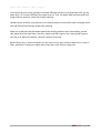
1
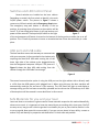
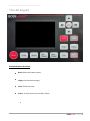
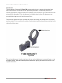
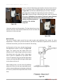
Operator’s Manual for LS series for RDWorks/LaserWORKS v8 251 Gordon Street Sanford, FL 32771 Phone 888-652-1555 • Fax 407-878-0880 www.BOSSLASER.com Table of Contents Your New Boss Laser ........................................ 1 CO2 Laser Safety/Policies ................................. 2 Unpacking and Setting Up ................................. 3 Setting up the Laser for first time ....................... 3 Switches and LED Control Panel ....................... 6 USB port and USB cable ................................... 6 Safe Materials for you and your laser ................ 6 The LED Keypad ............................................... 8 How to Focus the Lens .................................... 22 Using the Auto-Focus Option ........................... 22 Introduction to LaserWORKS .......................... 24 Tuning the Optics ............................................. 30 Lens Replacement ........................................... 33 Maintenance Schedule .................................... 35 Troubleshooting ............................................... 39 O P E R A T O R’ S M A N U A L F O R L S S E R I E S Your New Boss Laser To save time in the future, print a copy of this document. Click Print on the File menu, and press ENTER to receive the complete manual of examples and instructions. With the printed document in hand, position yourself in close proximity between the computer which you plan on using to draw and the laser’s LED panel. This will allow for complete access to all hardware and software controls and guide you through the basic operations of your new laser. The entire process from creating a design to pulling your finished work out of the laser is actually quite simple. There is a learning curve as with any new technology, but with some effort you will be running your new laser with confidence and speed in little time. BOSSLASER - Page | 1 O P E R A T O R’ S M A N U A L F O R L S S E R I E S CO2 Laser Safety/Policies Be careful. Laser machines are powerful tools, designed to cut or engrave with Warnings highly focused heat energy. Never leave your laser unattended while Fixture Reference running and never let anyone unfamiliar with your machine operate it Operations Always keep access covers on and top lid closed. Avoid any direct exposure and never stare at the laser light while operating. Notice and understand all of the warning labels attached to your machine. The following safety measures must be strictly enforced and abided by. Boss Laser shall not be held responsible for damages or injury resulting from improper use or dismantling of the laser machine. READLABELS • NEVER operate laser machinery unless you have been properly trained. • ALWAYS use protective eyewear, preferably wraparound goggles. • ALWAYS turn the Exhaust Fan on while running the laser. • NEVER set anything on top of the laser. • NEVER leave the laser unattended. Remain with the machine when it is running at all times so that you can hear and observe abnormalities and potential hazards. • Always maintain the machine’s environment free of heavy pollution such as strong magnetic electrical interference. • NEVER use unapproved or unsafe materials, such as Polyvinyl Chloride (PVC) or materials that emit noxious gases that can cause harm to your central nervous system. (See pages 6 & 7– Safe materials for you and your laser) • NEVER operate the laser near flammable and explosive substances. The UV light beam that is emitted is not visible and poses a great fire hazard. • NEVER open the upper cover of the laser machine while it is running & NEVER engrave a shiny metal or mirror. The laser beam can reflect and deviate (bounce around) which can cause Blindness or Serious Injury requiring medical attention. • NEVER push or pull the laser head and its gantry while the laser is running. • NEVER dismantle the laser machine. There are laser and high voltage/pressure parts that could cause harm or injury. In Case of Fire: 1. Press the EMERGENCY STOP button located above the LED Panel 2. Lift the lid 3. Quickly blow out the flame (or use a CO2 fire extinguisher for serious flames) BOSSLASER - Page | 2 O P E R A T O R’ S M A N U A L F O R L S S E R I E S Unpacking and Setting Up Once the delivery truck leaves, your new laser will be inside the large wooden box like the one in Figure 1. Make sure you are ready with necessary tools and plenty of room for laying out the parts and accessories of your new laser. Our crates are usually banded to a wooden pallet for safe shipping. Take a few minutes and check for any damage to the bands and crate. If you see any damage such as pierced or broken plywood take a picture before removing bands. If it looks smashed or opened take more pictures. The machine is insured for its value and may be damaged if the crate is badly damaged. Trucking companies are usually excellent at covering damage if any damage occurred during shipping. So document any issues. Figure 1 Now chances are no damage exist and you are ready to open that crate. Cut any bands. Then carefully remove the top lid. All of our crates will be secured by 2” staples. Carefully, pry out the staples around the crate. Be careful not to use any part of the plywood interior for a focal point on pry bar. Stay on the outside framing to ensure not piercing plywood and damaging machine. Once the top lid is off, look inside and find any loose boxes containing accessories. Remove any box that may fall when sides are removed. Remove front panel and then two side panels, then the back panel. Save the crate panels in the event you ever need to move the machine again. Setting up the Laser for first time Make sure to remove any foam material from inside of cabinet. Remove any plastic ties used for securing laser head from moving on x or y axis during shipping. Check for any loose nuts or bolts that may have come off during shipping in the bottom of cabinet. Depending on what options purchased with your laser, the crate will have several boxes outside of the laser cabinet. Additionally, some units will have accessories taped to the working table inside the cabinet. Locate and identify each of these. You should see the common items listed below and possibly some additional accessories: • • • • • External Fan with 4 inch duct flanges Water Pump for tube cooling (Only for LS-1416s w/o chiller. DO NOT use with water chiller) Air pump with tubing Tool box containing many necessary software and hardware components. Additional accessories such as rotary attachment, cutting table, custom jig etc. BOSSLASER - Page | 3 O P E R A T O R’ S M A N U A L F O R L S S E R I E S The LS & HP series of lasers from BOSSLASER come in two distinct styles. The smaller units are desktop machines with no lower cabinet designed to sit on top of some type of table or cabinet about 18 inches tall. The larger units have built in cabinets with lockable wheels requiring no lower stand. Note: Make sure to have purchased or built a stand (for LS-1416s) if needed before setting up your laser machine. The exhaust requires the most effort and its importance can’t be overstated. The laser vaporizes material as it moves along its axis, generating large amounts of smoke. Some materials like leather or wood generate much more. The exhaust is necessary to remove this by product. Duct exhaust to the outside, away from any area where coworkers may congregate. Correctly ducted, a laser can easily be placed in an office or spare room. Larger in-line exhaust fans are available through grainger.com or other industrial supply houses if your application requires constant cutting of material that gives off heavy smoke. Additionally, be certain to have the on/off switch within reach of the laser panel for easy access. This will have to be turned on each time laser is used. Figure 2 Larger machines with two exhaust ports. The LS-1630 (pictured in Figure 2) shows the typical exhaust outlets on all of the larger Boss Lasers. The top port with flange is designed to remove air from above the material, during engraving/etching for example. This is the most common of exhaust outlets to use. The lower port is designed to draw air from below the material, during cutting for example. This serves a double function. First, this port also removes air and all associated debris from the working area as soon as possible. Second, this lower unit will act as a vacuum to hold down light material such as cloth or paper. Notice there is no flange on the lower port. The tubing at the bottom of collector will come out of this port and connect directly to your exhaust duct work. BOSSLASER - Page | 4 O P E R A T O R’ S M A N U A L F O R L S S E R I E S The water pump (pictured in Figure 3) requires two lines; one to the water inlet and one to the water out barbed fixture. All BossLaser tubes are water cooled and the laser machine will not fire if water is not going through tube. The larger LS machines come with a water chiller (3000 or 5000). Our smallest comes with a water pump designed to rest on the bottom of some kind of water container, big enough to hold at least 4 gallons of distilled water. A simple solution is to use a 5 gallon bucket with three holes in the lid for two 3/8 inch flexible hose lines and the power cord. Make sure to not get lines reversed. Figure 3 The air pump (pictured in Figure 4) needs to be attached to the air inlet fixture. Figure 4 The purpose of the air pump is to blow air through the laser head therefore blowing debris and smoke away from the beam, while allowing for cleaner cuts and protecting the lens. The air pump on/off switch should also be close by and preferably on the same circuit as the water pump and exhaust fan to ensure its operation when running the laser machine. Notice the ground connector located on the back of the machine. This is an external ground designed to help eliminate static electricity. Just run the included ground wire from the connection to any grounded outlet or direct to earth. This step is not always necessary, but if you live in an area with low humidity it’s a good idea. Figure 5 The photo in Figure 6 shows a loop for those who did not receive a chiller with their laser machine. This would apply to most LS1415’s or LS-1416’s since the chiller is an option. Plug this into the Chiller Signal outlet as shown in Figure 5. Without this plugged in the laser will not fire. Once the above is attached and ready to operate your new laser machine is ready to go. Figure 6 BOSSLASER - Page | 5 O P E R A T O R’ S M A N U A L F O R L S S E R I E S Switches and LED Control Panel Several switches are installed on the laser cabinet. Depending on model, the first switch to identify is the main On/Off power switch. The picture in Figure 7 shows a common on/off main switch and the Emergency Stop button. The emergency stop push button is normally in the up position, by pressing down all power to the machine will be cut off. To re-set simply twist button, it will pop back up and Figure 7 power will be restored. The keyed on/off switch to the right of the red emergency off button is turned so the bottom of the key points to either the on or off position. This is a security measure to insure no unauthorized use. Store the second key in a safe place. USB port and USB cable The laser machine comes with two ways to communicate with your computer. A direct method is the simplest only requiring the data BLUE USB cable coming out of the lower right side of the cabinet to be plugged directly into the designated computer USB port. The picture in Figure 8 shows the blue USB cable exiting from the cabinet through the USB Cable Pass-through. Figure 8 The second communication option is using the USB port on the right cabinet side to directly read a .rd file from the USB memory stick plugged into it. When using this port the laser machine will automatically read the file and store it into memory. The LED panel will light up and display a message telling you file has been successfully uploaded and to remove the USB memory stick. Both of these options will be covered in more detail later in this manual. Safe Materials for you and your laser Lasers use heat to cut and etch a given material. Some materials respond to this method beautifully, others not so much. It is important to know the material you are working with, since some, like PVC are easy to cut, but give off a chlorine gas that’s not healthy for you or your machine. Below is a list to use as a guide. New materials come out daily, if you are not sure about its laser ability, contact us and we’ll try and identify its properties and determine if it’s both safe and possible. BOSSLASER - Page | 6 O P E R A T O R’ S M A N U A L F O R L S S E R I E S Plastics: o ABS (acrylonitrile butadiene styrene) o Acrylic (also known as Plexiglas, Lucite, PMMA) o Delrin (POM, acetal) o o o o o High density polyethylene (HDPE) – melts badly Kapton tape (Polyimide) Mylar (polyester) Nylon – melts badly PETG (polyethylene terephthalate glycol) Polyethylene (PE) – melts badly Polypropylene (PP) – melts somewhat Styrene Two-tone acrylic – top color different than core material, usually for custom instrumentation panels, signs, and plaques. o o o o Foam: o o o Depron foam – often used for RC planes. EPM Gator foam – foam core gets burned and eaten away compared to the top and bottom hard shell. Other: o o o o Cloths (leather, suede, felt, hemp, cotton) Papers Rubbers (only if they do not contain chlorine Teflon (PTFE, Polytetrafluoroethylene) Woods (MDF, balsa, birch, poplar, red oak, cherry, holly, etc.) Materials that can’t or should not be cut • Metals (Exceptions of Etching = Using TherMark. Cutting = HP models “Oxygen/Air assist”) • Polycarbonate (PC, Lexan) due to the fumes. • Any material containing chlorine o PVC (Cintra) – contains chlorine o Vinyl – contains chlorine HP (High Pressure) materials include all the above guidelines and as listed: • • • • Stainless steel up to 18 gauge Mild steel up to 18 gauge Thicker and denser woods Engrave steels by removing material to common depths BOSSLASER - Page | 7 O P E R A T O R’ S M A N U A L F O R L S S E R I E S The LED Keypad Introduction to the Keys Reset: Reset the whole system; Origin: Set the relative origin; Pulse: Pulses the laser Frame: To track by the current file’s frame; e BOSSLASER - Page | 8 O P E R A T O R’ S M A N U A L F O R L S S E R I E S File: The management of the memory and U disc files; Speed: Set the speed of the current running layer, or set the direction keys’ move speed; Max. Power: Set the max laser power of the current running layer, or set the power of “Pulse” Key; Min. Power: Set the min laser power of the current running layer, Start/Pause: To start or pause the work; Left & Right Arrow: To move the X axes or the left/right cursor; Up & Down Arrow:To move the Y axes or the up/down cursor; Z/U Button: The Z/U key can be pressed when the system is idle or the work is finished. On pressing this key, it will show some entries in the interface, each entry includes some functions, Z axes move, U axes move, each axes to go home etc.; Esc: To stop work, or to exit to some menu; Enter: Validate the change; BOSSLASER - Page | 9 O P E R A T O R’ S M A N U A L F O R L S S E R I E S Introduction to the Main Interface When the system is powered on, the screen will show as illustrated in Figure 9 Running parameters Graph display area File: Idle 00.00. 00 Count: Running Status 300mm/s MaxPow : 30.0%/30.0% X: 150.2 mm Y: 153.5 mm Z: 3000 mm 01 02 03 Running progress bar 99 X : 180. 5 mm Y : 235. 6 Working Number 01 Speed: 400 200 251 29 31 mm .0 .1 .5 Coordinate Graph layer parameters connect File dimension Net Status Figure 9 Graph Display Area: To display the whole file’s track, and display the running track. Running parameters: To display the running file’s file number, speed, max power etc.; Coordinate: To display the current coordinate of X,Y and Z axes Graph layer parameters: To display the layers’ information of the current file, such as max or min power, speed etc.. When system is idle, double click the layer, then users can change the layer’s parameters and the changing would be saved. Running Status: To display the current status of the machine, such as Idle, Run, Pause, Finish, etc.; Running Progress Bar: To display the progress bar of the current running file; Working Number: To accumulate the work number of the current file. File Dimension: To display the dimension of the current file; Net status: To display the connecting status of the Ethernet. BOSSLASER - Page | 10 O P E R A T O R’ S M A N U A L F O R L S S E R I E S When work is Idle or finished, all keys can be pushed, users can select a file to run, set some parameters, preview to a select file etc. But, when work is running or paused, some keys don’t respond when they are pushed. Speed key Push the “Speed” key when the screen is on the main interface, as shown in Figure 10 300 Speed: mm/s Modified press Enter Figure 10 Push the “X+/-“ Keys to move the cursor in the numeral area, and push the “Y +/-” keys to change the value, then push the “Enter” key to save the change, push the “Esc” key to invalidate the change. Max/Min power keys Push the “Max Power” or the “Min Power” keys when the screen is on the main interface, shown in Figure 11a-b MaxPower1: MaxPower2: 30.0 30.0 % % Press Z/U move item Modified press Enter Figure 11a BOSSLASER - Page | 11 O P E R A T O R’ S M A N U A L F O R L S S E R I E S MinPower1: MinPower2: 30.0 30.0 % % Press Z/U move item Modified press Enter Figure 11b When “Z/U” key is pushed, the green block can move up and down to denote the changing item, then “Y+/-” keys and “X+/-” keys can be used to change the value. Set the layer parameters After selecting a file to preview on the main interface, user can push “Enter” key to let the cursor move to the first layer, then “Y+/-” Keys can be pushed to select the intent layer, on that time, user can push “Enter” key to check the selected layer’s parameters, illustrated in Figure 12 01 02 03 Layer0: Speed: MinPower1: MinPower2: MaxPower1: MaxPower2: 400 mm/s 22.0 % 30.0 % 30.0 % 30.0 % Press Z/U move item Modified press Enter Figure 12 BOSSLASER - Page | 12 O P E R A T O R’ S M A N U A L F O R L S S E R I E S User can push “Z/U” Keys to move the green block on the intent parameter, then you could change the parameter if needed. “OK” to validate the change, and “Esc” to invalidate the change. Z/U Key The Z/U key can be pressed when the system is idle or the work is finished. On pressing this key, it will show some entries in the following interface (shown in Figure 13): Z move Language+ U move IP setup+ Axis reset+ Diagnoses+ Manual Set+ Screen Origin+ Laser Set+ Origin set+ Set Fact Para Def Fact Para Auto Focus Figure 14 Push “Y+/-” keys to move the green block to the anticipant item, and then push the “Enter” key to display the sub menu. Z move: When it is highligted on “Z Move” item, “X+/-” keys can be used to move the z axes. U move: When the green block is on “U Move” item, “X+/-” keys can be used to move the u axes. BOSSLASER - Page | 13 O P E R A T O R’ S M A N U A L F O R L S S E R I E S Axis reset+ When the green block is on this item, push the “Enter” key to show as below in Figure 14: XY axis reset X axis reset Y axis reset Z axis reset U axis reset Figure 14 Push the “Y+/-“ Keys to move the cursor to one of the entry, then push “Enter” key to restart the selected axis, the screen will show some information when resetting. Manual set+ When the green block is on this item, push the “Enter” key to show as below in Figure 15: Mode: manual: continue 300 mm Press Z/U move item Modified press Enter Figure 15 Push “Z/U” key to move the green block, and when the green block is on the “Mode” item, push “X+-“ keys to select the anticipant value, “Continue” or “Manual”. When “Continue” item is selected, then the “Manual” item is not valid, on that time, push the direction keys to move the corresponding axes, and when the pushed key is loosed, then the corresponding axes will finish moving. When the Mode item is “manual”, then pushing the direction key one time, the corresponding axes will move a fixed length, unless the scope is overstepped. BOSSLASER - Page | 14 O P E R A T O R’ S M A N U A L F O R L S S E R I E S Laser set+ When the green block is on this item, push the “Enter” key to show as below in Figure 16: Mode: continue 50 Laser Set: ms Press Z/U move item Modified press Enter Figure 16 Push “Z/U” key to move the green block, and when the green block is on the “Mode” item, push “X+-“ keys to select the anticipant value, “Continue” or “Manual”. When “Continue” item is selected, then the “Laser Set” item is not valid, on that time, push the Laser key to splash the enabled lasers, and when Laser key is loosed, then the lasers will finish splashing. When the Mode item is “manual”, then pushing the Laser key one time, the enabled lasers will splash a fixed time. Origin set+ When the green block is on this item, push the “Enter” key to show as below in Figure 17: Muti origin enable Origin enable1 Origin enable3 Origin enable2 Origin enable4 Set origin: 1 Next origin: 0 Press Z/U move item Modified press Enter Figure 17 BOSSLASER - Page | 15 O P E R A T O R’ S M A N U A L F O R L S S E R I E S Push “Z/U” key to move the green block to the anticipant item, and when the green block is on “enable” items, push “Enter” key to enable or disable the item, when enabled, the small diamonds is green, and when disabled, the small diamonds is grey. When the green block is on the “Set origin” item or the “Next origin” item, push the “X+-“ keys to select the value. Pay attention to if when the green block is on the “Set origin” item, push the “X +-“ keys to select a value, then, “Enter” key must be pushed to valid the change, or, the change is invalid. Each item introduced as below: Multiple Origins Enable: “Yes” or “No” can be selected. If you select “No”, the system will use the single-origin logic. You can press the “Origin” key and set the origin, and only this origin can become valid. If you select “Yes”, the system will use the multiple- origin logic and the “Origin” key on the keyboard become invalid. In such a case, the parameter of each origin must be set in the menu as follows. Origin Enable1/2/3/4: after the multiple-origin logic is enabled, the four origins can independently be prohibited and enabled. Set Origin 1/2/3/4: after the multiple- origin logic is enabled, you can stop the cursor at “Set as Origin 1/2/3/4”. Press the “Enter” key on the keyboard and the system will take the coordinate figures of current X/Y axles as the corresponding ones to the origin 1/2/3/4. Next Origin: there are such five digits as 0~4 for option, which are the origins to be used for the next figure. Origin 0 means the origin set by the “Origin” key on the panel in the single- origin logic. 1~4 means the serial number of the origins in the multiple- origin logic. Next origin can be modified to any one of origin 1~4, so as to control the start location of next work (the premise is that the origin is enabled), but it can’t be modified to origin 0. BOSSLASER - Page | 16 O P E R A T O R’ S M A N U A L F O R L S S E R I E S Auto Focus When the cursor stops at “Auto Focus”, press the Enter key to search for the focus (When there is z axes, and the z axes reset function is enabled, the auto focusing is valid); press the Esc key to return the prior menu. Language The item “Language” helps you to select a appropriate langue which is displayed on the pane (illustrated in Figure 18): Simplify Tradition English Figure 18 IP Setup When the green block is on this item, push the “Enter” key to show as below in Figure 19: IP address: 192 . 168 . 1 . 100 Gateway: 202 . 96 . 134 . 133 Press Z/U move item Modified press Enter Figure 19 Push “Z/U” key to move the changing item, then push “X+/-” keys and “Y+/-” keys to change the value, when all the IP value and the Gateway value are changed, push “Enter” key to validate the change, or “Esc” key to invalidate the change. BOSSLASER - Page | 17 O P E R A T O R’ S M A N U A L F O R L S S E R I E S Diagnoses If the “Diagnoses” item is pressed, the system will show as below in Figure 20: X Limit+ X Limit - Y Limit+ Y Limit- Z Limit+ Z Limit- U Limit+ U Limit- Water prot1 Water prot2 Open prot Read para Figure 20 This interface shows some system input information, such as limiter status, the status of the water protecting, and the status of the foot switch etc.. When the input is validated, the color frame will be green, otherwise it’s gray. Screen Origin If the “Screen Origin” item is pressed, the system will show as below in Figure 21: Origin locat: Top left To modify pressß /à Modified press Enter Figure 21 There are four entries to be selected: Top Left, Top Right, Bottom Left and Bottom Right. When one is selected, the previewed graph on the screen would be enantiomorphous based on X or Y direction. Note: Make sure the Origin location is set to TOP RIGHT BOSSLASER - Page | 18 O P E R A T O R’ S M A N U A L F O R L S S E R I E S File Key Memory File On the main interface, if “File” key is pressed, it will show as below in Figure 22: File: Count: 01 02 03 Read mem file Udisk+ Other+ Run Track File: 01 Speed: 300mm/s MaxPow: 30.0%/30.0% X: 150.2 mm Y: 153.5 mm Z: 3000 mm Work time Clear count Delete Copy to udisk Idle 00.00.00 Count: 99 X: 180.5 mm Y: 235.6 mm connect Figure 22 When showing this menu, the system would read the memory file firstly, the file name and the work times would be listed in the area, and the selected file is previewed in the bottom right area. “Y+/-” keys could be used to move the cursor on the file name list. When the cursor is on a target file name, presses the “Enter” key, the selected file will be previewed on the main interface, and then if “Esc” key is pushed, the preview will disappear. “X+/-” keys could be used to move the cursor left and right. All the item show as below: Read mem file: read the memory file list; Udisk: read the U disk file list; Other: the other operation of the memory files; Run: To run the selected file; Track: To track the selected file, and the track mode is optional; Work time: To forecast the running time of the selected file, and the time is accurate to 1ms; Clear count: To clear the running times of the selected file; BOSSLASER - Page | 19 O P E R A T O R’ S M A N U A L F O R L S S E R I E S Delete: To delete the selected file in the memory; Copy to Udisk: To copy the selected file to Udisk; If the “Other” entry is pressed, the system will show as below in Figure 23: Current work time Clear all count delete all file Format speedly Format drastically Total: 10 Clear Figure 23 Current work time: To forecast the running time of the current file(the current file No. is showed on the main interface), and the time is accurate to 1ms. Clear all count: To clear the running times of every file in the memory Delete all file: To delete all memory files Format speedily: To format memory speedily, and then all the files in memory will be deleted. Format drastically: To format memory drastically, and then all the files in memory will be deleted. Total: The total running times of all the files. U Disk File If the “Udisk” entry in Figure 22 is pressed, the system will show as Figure 24, and the operation method is all the same as Figure 22. BOSSLASER - Page | 20 O P E R A T O R’ S M A N U A L F O R L S S E R I E S File: 01 02 03 Read udisk Copy to memery Delete Figure 24 Read Udisk: Read the file list in the Udisk; Copy to memory: Copy the target Udisk file to the memory; Delete: Delete the selected Udisk file; BOSSLASER - Page | 21 O P E R A T O R’ S M A N U A L F O R L S S E R I E S How to Focus the Lens Focusing the lens must be re-done every time a new material thickness is placed on the working platform. The laser used highly focused energy to do its job, focusing becomes very important, and fortunately, very easy. In Figure 25, you can see the three components associated with correctly focusing the laser head. The focal guide, supplied with every laser, is placed upon the material used for the current job. The Z axis is moved by pressing the up or down arrow until the top of the focal guide lines up with the joint where the lens housing and bottom nozzle meet. That’s it. Your laser is now focused. That’s the science of focusing, now the art of focusing is simply adjusting in small increments up or down for different effects. As you get comfortable in the use of your laser these variables can be experimented with for all kinds of interesting results. Important! Always be careful when focusing thick material not to allow material to collide with the lens housing. This can cause serious damage to the laser machine. Figure 25 Using the Auto-Focus Option The auto-focus pen, an option on earlier machines, but standard on all our current models* that offer a Z-axis is a fast and easy way to get the material in perfect focus. *Note: Auto-Focus is not available on machines equipped with a 1.5” lens. Place material on the working area and press the Z/U button on the LED pad as shown on Page 8 (LED Control Panel). Make sure the probe, the thin pen like device to the left of the laser head, is positioned above the material you wish to cut/engrave. In this position, press the Z/U button, cycle down the menus until you see Auto Focus, select it and the Z-axis will automatically travel up until your material touches the probe, then back down to the perfect focal point. That’s it. Simple and fast. You are now focused and ready to etch/cut. BOSSLASER - Page | 22 O P E R A T O R’ S M A N U A L F O R L S S E R I E S The probe can be easily adjusted through the software to work with 2” lens or above. Figure 26 Under the User Parameters Tab (located in the Control Panel of LaserWORKS v8.), as illustrated in Figure 26, locate the Focus depth (mm) and change this value until focus is perfect and using your focal guide for accuracy. The setting above is 5.00 mm. Each lens is different. We set here at the factory to match your lens. Should the probe placement move or your change lenses this offset bounce back number will need to be adjusted. BOSSLASER - Page | 23 O P E R A T O R’ S M A N U A L F O R L S S E R I E S Introduction to LaserWORKS Main Interface of LaserWORKS Menu bar System bar Align bar Graphics bar Control panel Edit bar Layer bar The functions of the various components of the interface are as follows. Menu Bar: The main functions of the software are implemented through the Menu Bar. Commands executed through the Menu Bar include some of the most basic functions, including Document, Edit, Draw, Setting, Processing, View, and Help. System Bar: Some of the most commonly used command buttons chosen from the menu are placed on the System bar. Graphics Bar: Basic graphic attributes as graphic location, size, scale, and number processing as accessed through the graphics bar. Edit Bar: The default location of the edit bar is on the left of the work area. Tools that the user uses frequently can be placed in the edit bar to increase ease and flexibility of operation. Align Bar: Used to align selected objects. Layer Bar: Used to change the layering of selected objects. Control Panel: Used to complete laser processing of multiple tasks, including the setting of layer parameters, axis control, processing, and so on. BOSSLASER - Page | 24 O P E R A T O R’ S M A N U A L F O R L S S E R I E S Setting Laser Scan Parameters The input panel for setting laser scanning parameters (in Figure 27) is brought up by double clicking on the colored layer in the Work tab in the layer settings. Figure 27 Layer: The software can distinguish between different layers of processing and their parameters Is Output: This parameter has two settings, yes and no. If set to Yes, the corresponding layer will be output, whereas a No setting will result in the layer not being processed Speed: The corresponding processing method of processing speed. Note that when a smooth cut is paramount, slower processing should be used; faster processing causes the trajectory of the cut to be more erratic. If Default box is checked, the speed set on the Control Panel on your machine will be the speed at which the file is ran. Recommended Maximum "Scan" (Engraving) Speed: LS/HP-1416s = 375 mm/s LS/HP-2436s = 500 mm/s LS/HP-1630s = 400 mm/s LS/HP-3650s = 600 mm/s LS/HP-5298s & SS-3650s = Speeds will vary. Please contact manufacturer for details. "Cut" Speeds will vary depending on whether the material is going to be cut all the way through or lightly marked on. If Blowing: This setting takes note of whether the external fan is operating. If it is enabled, by clicking it, then this layer will open the fan if the user has created a “can” for the fan (if no can has been created, clicking this function has no effect). This should be always set to YES at all times. Processing Mode: This setting controls how the corresponding layer is processed. If the current layer is a vector layer (i.e., isa color layer), it includes three choices: Scan = Engraving, Cut = Cutting, and Dot = Dotting. If the current layer is a BMP layer (bitmap image), the Scan mode is only available. BOSSLASER - Page | 25 O P E R A T O R’ S M A N U A L F O R L S S E R I E S Laser 1, Laser 2: These settings corresponding to the motherboard laser signals 1 and 2. Note that laser 2 is meaningless if your machine only has one laser tube. Minimum power and maximum power: The power of the values range from 0 to 100, with 100 being maximum laser power and 0 being minimum. The minimum and maximum power should be set to the same values for a synchronous adjustment (consistent). If Default box is checked, the Min. & Max. power set on the Control Panel on your machine will be the power at which the file is ran. Seal: Closed cutting graphics do not require the use of sealing compensation, but unclosed graphics can be closed by means of it. If, however, the sealing is misplaced, there is no compensation. Either clearance optimization or backlash compensation can be used, depending on user preferences Open Delay: The delay at which the laser is turned on. This is a button for a time / medallion latency Close Delay: The delay at which the laser is turned off. Light off through wear / light off delay time Laser through mode: If checked, follows the % at which the Through power is set in respect to the power set in the layer parameters or control panel. Through power: Percentage at which the power is set to. Refers to crush objects in unit time of the work done fast. BOSSLASER - Page | 26 O P E R A T O R’ S M A N U A L F O R L S S E R I E S [Enable sew compensation]: Caused by laser cutting seam size of the graphics and graphic deviation of actual cutting out. Seam width compensation only applies to closed graphics. [Sew Direction]: According to the actual need to set up, such as cutting a circle. If you want to keep the circle from being cut off, you should set the direction of compensation outward, if want to keep the hole, should set the direction of compensation inward. [Sew width]: This sets the laser cutting seam width Laser Scanning Parameters Setting Figure 28a Figure 28b In Figure 28a are vector scanning parameters, while Figure 28b contains settings for scanned bitmap parameters. Vector data do not support scanning the color carving, optimization scanning, or direct output. Optimal scanning. Choose optimal scanning to automatically adjust the scan to the scanning interval for best effect. Otherwise, the user settings of the scanning interval scan pattern are applied. It is generally advisable to choose "optimal scanning." Output direct. As referred to the image (Grayscale Bitmap), higher power will be assoicated with deep/dark colors, on the other hand, for shallow/light colors will have lower power outputs. BOSSLASER - Page | 27 O P E R A T O R’ S M A N U A L F O R L S S E R I E S Scan mode: There was four different scanning modes: X_unilateralism, X_swing, Y_unilateralism and Y_swing X_unilateralism: The scanning pattern of a back and forth motion in a horizontal direction, in which the laser is pulsing/shooting from left to right OR right to left (uni-directional). X_swing: Refers to the optical horizontal direction in the back and forth scanning of graphics, in which the laser is pulsing/shooting from left to right AND right to left (bi-directional). Y_unilateralism: The scanning pattern of a back and forth motion in a vertical direction, in which the laser is pulsing/shooting from up and down OR down and up (uni-directional). Y_swing: Refers to the optical vertical direction in the back and forth scanning of graphics, in which the laser is pulsing/shooting from up and down AND down and up (bi-directional). Interval (mm): Refers to the optical scan and its distance under a line. The smaller the interval, the more deeply the graphics are scanned, and vice versa. Suggestions: For vector layers (i.e. color layers), the scanning interval should be set to 0.1 mm or less. For a tutu layer (i.e., a BMP layer), the scanning interval should be set to 0.1 mm or above. Then change the maximum power to make the minimum power after scanning the graphics depth to achieve the ideal effect. Laser Dot Parameters Setting The time for emitting laser on one dot during the process. The higher the value is, the darker The interval between the dots Dot length, for cutting dash line Only dot at center BOSSLASER - Page | 28 O P E R A T O R’ S M A N U A L F O R L S S E R I E S Sending files to the laser using LaserWORKS Layer settings Processing control Save To UFile: Clicking this button saves the current file as an RD file which can be used for offline processing. The file can be copied to another memory board for full offline operation. Use this option to export your file(s) to a USB flash drive, then to import into your machine. Download: Clicking this button downloads the file to the memory of the controller, where the user can start it through the machine panel. Use this option to send your file(s) directly to your machine. Output select graphics If Output select graphics is checked, only the selected graphics will be outputted to the machine. If Selected graphics position is checked, the selected graphics will be outputted, in position of your machine's worktable, in respect to the position set in the software. Now that you have the file sent to your machine. Go on the LED control panel, press File and locate your file that you sent to the machine. While it is highlighted, you should see the preview of your image that reflects that file. Once you have that, press Enter on the file and you are ready to go! See the FULL software manual of LaserWORKS for more in-depth features! BOSSLASER - Page | 29 O P E R A T O R’ S M A N U A L F O R L S S E R I E S Tuning the Optics NOTE: Upon receiving your machine, all machines go through a QA (quality assurance) process AND are already aligned, ready for use. So there’s no need for any adjustments with the mirrors/ tube/bracket. This section is only for providing prior knowledge on how to adjust/tune the laser. The laser tube and optics are the heart of the laser machine. It is important to understand the basics, allowing you to get the most out of your machine. Once tuned the laser machine should stay aligned for months of work. Check it once every month to insure no bumping or mechanical failure has occurred. By studying the diagram in Figure 29a, you can see the simplicity of the system: One long glass tube, two small mirrors and a laser head, that’s it. The light/laser travels in a straight line, adjusting the laser tube in the rear to hit first mirror (A) dead center first, then adjust mirror (A) to hit mirror (B) dead center. And finally adjust mirror (B) to hit laser head dead center. Be careful with this procedure. Never have the machine on while working around the laser tube. Make an adjustment, then turn on the laser and fire a test shot by pressing the LASER button on the LED panel. Figure 29a BOSSLASER - Page | 30 O P E R A T O R’ S M A N U A L F O R L S S E R I E S Tube Bracket The tube bracket, illustrated in Figure 29b, does just what it says, it secures the long glass laser tube to the cabinet. The bracket has two adjustment parameters. You basically can move it vertically up and down, and horizontally front and back. The two bolts on top of the bracket are not to be used for adjustment. Their sole purpose is to hold the tube in place. All adjustments are accomplished using the vertical and horizontal bolts. The horizontal adjustment bolts are under the bracket and through the cabinet metal. Once loose, you have about .5 inch travel from front back. Both brackets have the slotted holes machined in the cabinet for this purpose. Figure 29b The vertical adjustment is simple, just loosen the two vertical adjustment screws and lower or raise the upper bracket. With these two adjustment parameters aligning the tube to hit the first mirror requires little effort. BOSSLASER - Page | 31 O P E R A T O R’ S M A N U A L F O R L S S E R I E S Figure 30a An easy method of identifying exactly where the laser beam hits the mirror is to place a piece of masking tape over the mirror as shown in Figure 30a. Use the least adhesive tape you can find. The laser will quickly burn through the tape leaving its mark as shown in Figure 30b. Using to strong an adhesive just lease a mess to clean up afterwards. Remember to use caution, if the laser is way off target, it could literally shoot into the room, missing the mirror, the cabinet and hitting someone or something. This could be dangerous. Use extra caution on this procedure. The laser beam has no color and can’t be seen. Once finished make sure mirrors are clean and continue on to the next step. Figure 30b Mirror Bracket The mirror bracket works much like the tube bracket with additional fine screws for micro adjustments. Chances are you will not have to use either of the Macro adjustments for vertical or horizontal corrections, just the micro screws for fine tuning. An illustration of the mirror bracket showing the fine-adjustment screws is shown on Figure 30c. Again, use caution and only adjust when the machine is off. If after firing a test shot no burn hole shows up on the tape, make a large target with a piece of cardboard to see where laser mirror A is pointed. Using just the fine adjustment screws, you should be able to bring the beam right to the center of mirror B. After tuning mirror A to hit mirror B perfectly, adjust mirror B to hit the laser head dead center. Use the same masking tape technique to adjust all the mirrors, and the tune-up will be done in little time. Figure 30c BOSSLASER - Page | 32 O P E R A T O R’ S M A N U A L F O R L S S E R I E S Lens Replacement Lenses are one of the few parts of a laser machine that need regular maintenance, primarily regular cleaning. Lens cleaning is simple if done often, difficult or not possible if rarely done. The lens is small, about 20 mm across, with 2 distinct sides, one flat and one convex or curved out. When reinstalling, the curved side always faces the laser path, away from the working platform. As illustrated in Figure 31, the lens assembly consist of 2 main parts, the lens tube (also known as the lens housing) and nozzle, then 3 parts inside the lens tube. The lens, washer and slotted ring nut. To remove lens for replacement or cleaning, loosen the friction set screw on the main lens housing holding the lens tube in place. After loosening set screw the lens tube should slide out of the housing. Separate the lens tube from the nozzle like the illustration shown in Figure 31. Your laser tool box came with a tool for removing the slotted ring nut. The tool looks more like a scraper than a screw driver. Its width is designed to fit inside the lens tube and fill the slots. Be careful not to let the blade tip slip and scratch the lens. Once the slotted ring is out, the rubber washer will keep the lens pressed against Figure 31 the laser tube. Using a pencil with eraser, insert the eraser end into the laser tube and push out the lens. Both lens and washer will fall out the large end. BOSSLASER - Page | 33 O P E R A T O R’ S M A N U A L F O R L S S E R I E S At this point the lens can be replaced or cleaned. Different size lens can be inserted as well, just be aware that a 4” lens has a different focus point than a 2” lens. The beam width increases with focal length and may require a nozzle with a larger opening. Handle the lens carefully, using acetone or lens cleaner/wipes to clean the flat side. Lens paper works well and should show a brown residue after cleaning. Make sure to place the flat side down towards the working platform when reassembling, curved side always faces the laser beam. Lens first, washer and then ring nut. Don’t over tighten ring nut, just snug it up against the washer, and then a quarter turn more. Burned lenses are a common problem for new users of any laser machine. Make sure to clean it often, especially if cutting on a regular basis. Kept clean a lens will last a long time. BOSSLASER - Page | 34 O P E R A T O R’ S M A N U A L F O R L S S E R I E S Maintenance Schedule Focal lens: This is the lens that is used to focus the laser beam. This lens should be cleaned at least once per week. It is not possible to clean the lens while it is mounted in the focal tube. The laser beam alignment should be checked after cleaning is completed. If there is any incident of fire or large issue of smoke/fumes, then it is advised to check the lens and clean it. Use denatured alcohol and/or acetone as the cleaning solvent. Use a lens tissue or cotton tipped swabs (Q-Tips) to apply the solvent. Len wipes with alcohol-free solution will also do the trick. Do not scrape the lens. Use the solvent to dissolve the dirt from the lens surface. Only use a soft swirling motion when applying the solvent. Use a dry swab in soft swirling motion while evaporating the solvent. Use as many swabs as needed to result in a clean lens surface. The lens surface should be somewhat difficult to see. Look at a reflection in the lens to help see dirt on the surface. Make sure to clean the lens and not leave water marks or dirt smears. The focal lens should be replaced if it is cracked, the coating is scratched/pitted, the core material is darkened, the coating is delaminating, or any other significant damage is found. Some minor blemishes are acceptable, but these problems waste power and will result in reduced laser power at the target material. Any dirt, contaminate, or damage to the lens will cause the lens to become damaged faster. Mirror #3 (in the laser head): This mirror is located directly above the focal lens. This mirror should be cleaned at least every one month. If there is any incident of fire or large issue of smoke/fumes, then it is advised to check the mirror and clean it. It is possible to clean the mirror in its mounting bracket, but highly advised to remove the mirror from position and thoroughly clean it. The laser beam alignment should be checked after cleaning is completed. Use denatured alcohol and/or acetone as the cleaning solvent. Use a lens tissue or cotton tipped swabs (Q-Tips) to apply the solvent. Len wipes with alcohol-free solution will also do the trick. Do not scrape the lens. Use the solvent to dissolve the dirt from the lens surface. Only use a soft swirling motion when applying the solvent. Use a dry swab in soft swirling motion while evaporating the solvent. Use as many swabs as needed to result in a clean surface. The mirror surface should be difficult to see. Look at a reflection in the mirror to help see dirt on the surface. Make sure to clean the lens and not leave water marks or dirt smears. The mirror should be replaced if it is pitted/scratched, rusted, discolored from heat damage, or any other significant damage is found. Some minor blemishes are acceptable, but these problems waste laser power and will result in reduced laser power at the target material. Any dirt, contaminate, or damage on the mirror will cause the mirror to become damaged faster. Mirror #2: This mirror is located directly at the end of the gantry rail. This mirror should be cleaned at least every two months. Use the same directions as found for Mirror #3 BOSSLASER - Page | 35 O P E R A T O R’ S M A N U A L F O R L S S E R I E S Mirror #1: This mirror is located directly in front of the laser tube. This mirror should be cleaned at least every three months. Use the same directions as found for Mirror #3 Laser tube output coupler lens: This lens is located inside the output end of the laser tube. This lens should be cleaned at least every three months. You must be very careful when cleaning this lens. This lens cannot be removed from the laser tube. You can use a Q-tip for applying the acetone. Len wipes with alcohol-free solution will also do the trick. Be gentle. The ideal situation is that you are only removing dust, film contaminate from humidity, or smoke fumes. Do not scratch this lens. It is not replaceable. Linear rails: The linear rails are the guiding rails along the left and right sides, and across the gantry. These rails should be clean, without rust, and have a slight glaze coating of some oil. The linear rails should be given some attention about every month. The surfaces of the metal should always have oil on it such that it is wet to the touch. The best way to see that you need to do some cleaning is to check the end of the rail near where the home switch is located. If you see a dirt line, then clean the rails off and apply fresh oil. Linear bearings: The linear bearings are found under the gantry (to mount the gantry to the side rails) and under the focal head (to mount the focal head to the gantry). These bearings have grease fittings for pushing lubricant into the ball bearing areas. You might not have a special grease pump to lubricate the bearings. Try the cheap and easy approach. 1) Remove the grease fitting, 2) Apply the grease to your finger, 3) Push the grease into the little hole, 4) push more grease into the little hole, 5) go to step #2 ..... 6) Put the grease fitting back on. Rubber belts: The rubber belts should be checked for appropriate tension at least every six months. You should expect the two side belts to be the same tension and should be tensioned at the same maintenance schedule. These side belts work together to move the gantry from front to rear. If one belt is tensioned more often than another, then that belt could become stretched more than the other. It is difficult to describe how tight the belts should be, but there should not be a slack, sagging, or flapping. If the belt appears to be worn on one side, check the bearing alignment or damage to the matching bearings. There are many laser machine designs, but the method of changing the belt tension should not be too complex. It is normally a method of tightening a screw and then applying a lock nut to keep the screw in place. Air filters: Please consult your user appropriate user manual(s) for cleaning or replacing the air filters. Air filters work best when air is able to move through them and catch the specs of dust, fumes, and other crap in the air. If a filter is too dirty, then the air pressure will be adversely reduced. It can be very important to get the bad smells out of the room. Some off-gasses from the laser cutting process can be caustic, nauseating, volatile, corrosive, or even deadly. It is best to use multiple stages of filters to catch the different sizes of particles. BOSSLASER - Page | 36 O P E R A T O R’ S M A N U A L F O R L S S E R I E S Nuts/Bolts: If concerned about these items rusting, then you should apply a thin coating of silicone base grease. One application per year should be enough. Coolant: Firstly, automotive antifreeze should not be used as a laser coolant. The best coolant is deionized water. In the absence of deionized water, distilled water can be used. Tap water should be a much later resort. The coolant should always be clean and clear. It is a common problem for the coolant to become infested with mold. This often looks like a murky green water with algae build up on the inner walls of the hoses. The solution is a multi-step process. 1. Flush out the bad water 2. Add fresh water with 20 percent bleach. Cycle the bleach-water for 30 minutes. Flush this water out also. 3. Switch the inlet and outlet hoses and flush with more water. This should dislodge mold from inside the laser tube. 4. The flow safety sensor could also be full of mold. The best solution is to take it apart and clean with a soft brush or pipe cleaners. Make sure to re-assemble the sensor correctly and without leaks. It is possible that harsh cleaners could creep into the sensor electronics and cause permanent damage. Storage of the laser: Clean, dry, warm location with No vibration. Use a dehumidifier: Humidity can cause the metal parts of the laser machine to rust. All metal is expected to rust. One unexpected metal surface is the laser mirrors. It is best to try to control the humidity level in the laser work area. Clean the mirrors and check for this oxidation as a possible problem. Replace mirrors that do not meet your expectation of performance. Make a maintenance schedule: The easiest way to follow a cleaning schedule is to buy a calendar and write on the dates that you want to do the maintenance. Some maintenance is needed on a regular basis while other cleaning could be an immediate requirement after a disaster. Just know that avoiding the maintenance of your laser could result such that the laser doesn't work right ...or doesn't work at all. BOSSLASER - Page | 37 O P E R A T O R’ S M A N U A L F O R L S S E R I E S Use a heater: If your laser is expected to be exposed to temperatures below 50 degrees Fahrenheit, then use a heater. The laser machine is a significant investment and should be kept warm. It is easy to put a ceramic space heater inside the laser machine with the temperature set to something moderate. The heat will move throughout the inside of the laser and keep the glass laser tube warm enough to not freeze or crack. A sudden shock of icy cold water rushing into the warm glass can break the glass laser tube. What to do about the water pump, bucket, or chiller? You have a few options: 1) Use an aquarium heater to warm the water. Set the temperature to a moderate level. The water in the hoses could still freeze. Use a simple timer switch to turn the water pump on/off every fifteen minutes. 2) If you are worried about wasting the life of your water pump, then drain the laser coolant from the entire system. Disconnect the hoses from the laser machine. Use an air compressor to blow out as much water as you can (Blow air into the hose that water comes out of the laser machine. This should clear out the most water). Take the chiller to somewhere that will not freeze. Put a heater inside the laser machine. 3) Move the laser machine system to somewhere warm. BOSSLASER - Page | 38 O P E R A T O R’ S M A N U A L F O R L S S E R I E S Troubleshooting Laser not coming on First make sure power receptacle the laser is plugged into has working power. Plug in some other device, like a lamp or power drill and check for power. Check the simple stuff first. • Is the emergency kill button pressed? • Is the key turned to the on position? • Check the 120v 5amp fuse located in the receptacle used to power up the laser. The fuse is a pull out type at the bottom of the receptacle. • Check the re-settable fuse box (breaker), make sure the lever is in the on position. Not all units will have this fuse. Machine coming on but not firing The laser has several protection modes built in to prevent possible injury or machine damage. Problems with any of these systems will prevent the laser from actually firing, although the head will still move around like the machine is working fine. • Check the water supply. If the laser does not detect water flowing through the tube the laser will not fire, so make sure either your water pump (for LS-1416’s) or CW-3000/5000 water chiller is on. • Make sure all doors are closed. All our machines come with interlocks to prevent operation in the advent lid or doors are open X or Y Slop Over Error / Frame Over Error When running the Frame and/or START-PAUSE button, the Slop/Frame error message will appear only if the object(s)/image(s) being executed on the worktable is overextending (too big and/ or not enough space on the worktable to be done) The file/job keeps starting at the same spot every time In most cases, this happens when the “ORIGIN” was accidentally selected. To cancel the origin, press the Z/U button and cycle through the options until you see Axis Reset+. Select it and then highlight over the XY axis reset. Once that is selected, the laser head will go to it's home position and now the origin has been cancelled. To change the origin position, just move the laser head to your desired location, then press the ORIGIN button again to set the origin. BOSSLASER - Page | 39 O P E R A T O R’ S M A N U A L F O R L S S E R I E S HARDWARE: Water Pump – Mainly for the LS-1416s, only use if you do not have a water chiller (CW- 3000/5000). If you have a CW-3000/5000 water chiller, the water pump is not needed. Please do NOT put the water pump in series with the chiller! Water Chiller (for CW-3000/5000 Models) – Mainly for the 1416s with 60W tubes and higher LS models. If the water chiller’s alarm is going off (beeping noise), it’s either (1) the water hoses are pinched so the water flow is being stopped. (2) The water chiller is low in water and (3) The temperature is either below or above the alarm levels (refer to the CW-3000/5000 manual for default temp. levels) Air Pump – Produces around 20 lbs. of pressure and NEEDS to be on at all times when running a file/job on your machine. Not doing so, will damage your lens and/or the machine itself. BOSSLASER - Page | 40