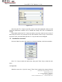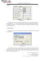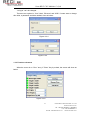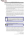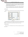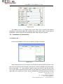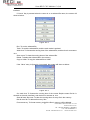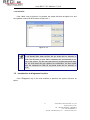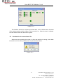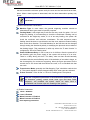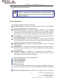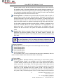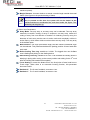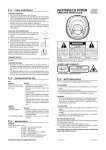
1
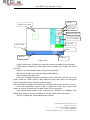
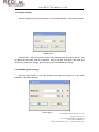
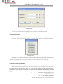
Jinan RECI CNC Machine Co.,Ltd User’s Manual of Control System Jinan RECI CNC Machine Co.,Ltd www.recicnc.com Tel: +86-531-88785511 58053876 Fax: +86-531-88785511 E-mail: [email protected] [email protected] Jinan RECI CNC Machine Co.,Ltd Copyright Declaration Jinan RECI CNC Machine Co.,Ltd. reserves all rights. Jinan RECI CNC Machine Co.,Ltd. (hereinafter referred to as “RECI.”) holds the patent right, copyright and other intellectual property rights for this product and its related software. Without authorization, no one is allowed to copy, manufacture, process and use this product and its relative parts directly or indirectly. RECI is entitled to increase or reduce and modify the shape and functions of this product stated herein as well as amend any documents attached to this product, without prior notification. The users should peruse this Manual prior to using the product stated herein.RECI. shall not be responsible for the direct, indirect, special, incidental or corresponding losses or damages arising out of improper use hereof or of this product. The machine in operation is dangerous, so the users are obliged to design and institute the effective mechanism for error handling and safety protection.RECI. shall not undertake any duties or responsibilities for the incidental or corresponding losses arising therefrom. II Jinan RECI CNC Machine Co.,Ltd www.recicnc.com Tel: +86-531-88785511 58053876 Fax: +86-531-88785511 E-mail: [email protected] [email protected] Jinan RECI CNC Machine Co.,Ltd CONTENTS 1 OPERATING INSTRUCTION OF PANEL.....................................................................................23 1.1 INTRODUCTION TO THE KEYS.................................................................................................. 23 1.1.1 Introduction to the whole panel.........................................................................................23 1.1.2 Introduction to the keys......................................................................................................23 1.2 INTRODUCTION TO THE INTERFACE FUNCTIONS....................................................................... 25 1.2.1 The screen of power on..................................................................................................... 25 1.2.2 The main interface.............................................................................................................. 25 1.2.3 Speed settings.....................................................................................................................26 1.2.4 Max/Min power settings..................................................................................................... 27 1.2.5 Reset the axes.................................................................................................................... 28 1.2.6 Set the layer parameters................................................................................................... 28 1.3 INTRODUCTION TO MENUS....................................................................................................... 29 1.3.1 Sys info.................................................................................................................................29 1.3.2 Sys config.............................................................................................................................30 1.3.3 Function sub menu............................................................................................................. 31 1.3.4 User para............................................................................................................................. 33 1.3.5 Machine para.......................................................................................................................33 1.4 INTRODUCTION TO FILE FUNCTION.............................................................................................. 34 1.4.1 Memory file.......................................................................................................................... 34 1.4.2 Udisk file...............................................................................................................................35 1.5 INTRODUCTION TO DIAGNOSES FUNCTION................................................................................... 36 1.6 INTRODUCTION TO SOME ALARM INFO........................................................................................ 36 2 MANUFACTURER/USER PARAMETERS EXPLANATION......................................................37 2.1 MANUFACTURER PARAMETERS......................................................................................................37 2.2 USER PARAMETERS........................................................................................................................ 40 III Jinan RECI CNC Machine Co.,Ltd www.recicnc.com Tel: +86-531-88785511 58053876 Fax: +86-531-88785511 E-mail: [email protected] [email protected] Jinan RECI CNC Machine Co.,Ltd 1 Operating Instruction of Panel 1. Introduction to the Keys 1.1.1 Introduction to the whole panel 1.1.2 Introduction to the keys “Reset” Key :Reset the whole system; “Origin” Key :Set the relative origin; “Laser” Key :Let the Laser to splash; “Frame” Key :To track by the current file’s frame; 4 Jinan RECI CNC Machine Co.,Ltd www.recicnc.com Tel: +86-531-88785511 58053876 Fax: +86-531-88785511 E-mail: [email protected] [email protected] Jinan RECI CNC Machine Co.,Ltd “File” Key “Speed” Key :The management of the memory and U disc files; :Set the speed of the current running layer, or set the direction keys’ move speed; “Max Power” Key :Set the max laser power of the current running layer, or set the power of “Laser” Key; “Min Power” Key :Set the min laser power of the current running layer, “Stop” Key “Start/Pause” Key “X+/-” Keys :To move the X axes or the left/right cursor; “Y+/-” Keys :To move the Y axes or the up/down cursor; “Z+/-” Keys :To move the Z axes or change the parameter pages; “HOME” Key “Menu” Key “Diagnose” Key :To stop the work; :To start or pause the work; :Let the selected axes go back to absolute origin; :Set the system parameter; :Diagnose the system, such as the limiter status, water protect etc.; “Esc” Key :To stop work, or to exit to some munu.; 5 Jinan RECI CNC Machine Co.,Ltd www.recicnc.com Tel: +86-531-88785511 58053876 Fax: +86-531-88785511 E-mail: [email protected] [email protected] Jinan RECI CNC Machine Co.,Ltd 1.2. “Enter” Key : Validate the change; “Numeral” Keys “Dot” Key :To set the parameters; “CL” Key :To cancel the last settings; ~ :To set the parameters; Introduction to the interface functions 1.2.1 The screen of power on When the system is powered on, the screen will show as below: Figure: 8.2-1 This power on screen can be changed by user. If the user-defined graph is downloaded by the PC software, when restart the system, it will show the new graph. 1.2.2 The main interface When the system finished searching the machine origin, the screen will show as below: 6 Jinan RECI CNC Machine Co.,Ltd www.recicnc.com Tel: +86-531-88785511 58053876 Fax: +86-531-88785511 E-mail: [email protected] [email protected] Jinan RECI CNC Machine Co.,Ltd File No. Graph Preview Area Work speed Laser max power X,Y,Z’s coordinate Layer Info. System status Data Work No. Net status Figure: 8.2-2 Graph Preview Area: To display the whole file’s track, and display the running track. System status: To display the current status of the machine, such as Idle, Run, Pause, Finsh, etc.. Work No.:To accumulate the work number of the current file. Net status:To display the connecting status of the ethernet. Data:To display the system time. Layer Info.:To display the layers’ information of the current file, such as max or min power, speed etc.. When system is idle, dblclick the layer, then users can change the layer’s parameters and the changing would be saved. XYZ’s coordinate:To display the coordinate of XYZ axes, and the size accurate to 0.1mm. Laser max power:When system is idle, to display the “Laser” key’s power, when system is running, to display the max laser power of the running layer. Work speed: When system is idle, to display the “Up/Down” or “Left/Right” key’s speed, when system is running, to display the running speed of the current layer. File No.:To display the current selected file’s number. 7 Jinan RECI CNC Machine Co.,Ltd www.recicnc.com Tel: +86-531-88785511 58053876 Fax: +86-531-88785511 E-mail: [email protected] [email protected] Jinan RECI CNC Machine Co.,Ltd 1.2.3 Speed settings Push the “Speed” key when the screen is on the main interface, it will show as below: Figure: 8.2-3 Push the “X+/-“ Keys to move the cursor in the numeral area, then push the “CL” key to delete the old value, push the “Numeral” Keys to set the new value, then push the “Enter” key to save the change, push the “Esc” key to invalidate the change. 1.2.4 Max/Min power settings Push the “Max Power” or the “Min Power” keys when the screen is on the main interface, it will show as below: Figure: 8.2-4 8 Jinan RECI CNC Machine Co.,Ltd www.recicnc.com Tel: +86-531-88785511 58053876 Fax: +86-531-88785511 E-mail: [email protected] [email protected] Jinan RECI CNC Machine Co.,Ltd Figure: 8.2-5 The way of changing the parameters is all the same as changing speed. 1.2.5 Reset the axes Push the “Home” key when the screen is on the main interface, it will show as below: Figure: 8.2-6 Push the “X+/-“ Keys to move the cursor to one of the entry, then push “Enter” key to restart the selected axes, the screen will show some information when reseting. 1.2.6 Set the layer parameters After selecting a file to preview on the main interface, user can push “Enter” key to let the cursor move to the first layer, then “Z+/-” Keys can be pushed to select the intent layer, on that time, user can push “Enter” key to check the selected layer’s parameters, show as below: 9 Jinan RECI CNC Machine Co.,Ltd www.recicnc.com Tel: +86-531-88785511 58053876 Fax: +86-531-88785511 E-mail: [email protected] [email protected] Jinan RECI CNC Machine Co.,Ltd Figure: 8.2-7 User can push “Z+/-” Keys to move the cursor on the intent parameter, then he could change the parameter if needed. “OK” to validate the change, and “Exit” to invalidate the change. Here please notice that “Z+/-” Keys are used to move the cursor but not to move Z axes when the cursor is on the layer on the main interface, that’s to say, if user want to move the Z axes, he would firstly push the “CL” key to let the cursor disappear. 1.3 Introduction to menus Push the “Menu” key when the screen is on the main interface, it will show as below: Figure: 8.3-1 Push “Y+/-“ keys to select the intent entry, then push “Enter” Key to check the sub menu. 1.3.1 Sys info When the cursor is on “Sys info” entry, if “Enter” Key is pushed, the screen will show 10 Jinan RECI CNC Machine Co.,Ltd www.recicnc.com Tel: +86-531-88785511 58053876 Fax: +86-531-88785511 E-mail: [email protected] [email protected] Jinan RECI CNC Machine Co.,Ltd as below: Figure: 8.3-2 The default cursor is on “Read” button, push “Enter” key to read all the system info. and the limit info.. “Z+/-“ keys could be used to move the cursor, and when the cursor is on “System info” label, “Y+/-“ keys could be used to change the label between “System info” and “Limit info” 1.3.2 Sys config When the cursor is on “Sys config” entry, if “Enter” Key is pushed, the screen will show as below: Figure: 8.3-3 The default cursor is on “Read” button, push “Enter” key to read the config information. “Z+/-“ keys could be used to move the cursor to select the intent label. If some value is changed, move the cursor to “Write” button and push “Enter” key, then the changed value could be saved. 11 Jinan RECI CNC Machine Co.,Ltd www.recicnc.com Tel: +86-531-88785511 58053876 Fax: +86-531-88785511 E-mail: [email protected] [email protected] Jinan RECI CNC Machine Co.,Ltd “Lcd type” can’t be changed. There are two options in “Com” label, “Ethernet” and “USB”. If users want to change this value, a password would be needed, show as below: Figure: 8.3-4 Figure: 8.3-5 1.3.3 Function sub menu When the cursor is on “Func” entry, if “Enter” Key is pushed, the screen will show as below: Figure: 8.3-6 12 Jinan RECI CNC Machine Co.,Ltd www.recicnc.com Tel: +86-531-88785511 58053876 Fax: +86-531-88785511 E-mail: [email protected] [email protected] Jinan RECI CNC Machine Co.,Ltd If the cursor is on “Origin X enable”, push “Enter” key to enable or disable the selected origin, if it’s enabled, the color frame would be red, otherwise it’s green. Multiple Origin Enable: “Yes” or “No” can be selected. If you select “No”, the system will use the single-origin logic. You can press the “Origin” key and set the origin, and only this origin can become valid. If you select “Yes”, the system will use the multiple- origin logic and the “Origin” key on the keyboard become invalid. In such a case, the parameter of each origin must be set in the menu as follows. Origin X Enable: After the multiple-origin logic is enabled, the four origins can independently be prohibited and enabled. Set Origin 1/2/3/4: after the multiple- origin logic is enabled, you can stop the cursor at “Set as Origin 1/2/3/4”. Press the “Enter” key on the keyboard and the system will take the coordinate figures of current X/Y axles as the corresponding ones to the origin 1/2/3/4. Next Origin: there are such five digits as 0~4 for option, which are the origins to be used for the next figure. Origin 0 means the origin set by the “Origin” key on the panel in the single- origin logic. 1~4 means the serial number of the origins in the multiple- origin logic. Next origin can be modified to any one of origin 1~4, so as to control the start location of next work (the premise is that the origin is enabled), but it can’t be modified to origin 0. Prompt Once the multiple- origin logic is selected and if the serial number of the next origin is 1 and four origins are enabled, when the memory file function is started or the processing file is uploaded into the PC and this file selects “Take the Original Origin as current Origin”, the work started for each time will use different origins. The rotation order of origin is 1->2->3->4->1->2……. Origin location: There are four entries to be selected: Top Left, Top Right, Bottom Left and Bottom Right. When one is selected, the previewed graph on the screen would be enantiomorphous based on X or Y direction. This item is only used to preview the file on the screen, and it is invalid to the machine’s movement. Caution Set Para: After the “Set Para” is selected and the Enter key pressed, the interface will show the specific password to be entered when set as default parameter. After the manufacturer regulates all parameters of the machine well (including all manufacturer parameters and user parameters), this function can be used to store the well-regulated parameters to help users to recover the original parameters (including all manufacturer parameters and user parameters) through selecting “Recover Para” when they regulate parameters improperly. 13 Jinan RECI CNC Machine Co.,Ltd www.recicnc.com Tel: +86-531-88785511 58053876 Fax: +86-531-88785511 E-mail: [email protected] [email protected] Jinan RECI CNC Machine Co.,Ltd Recover Para: After the “Recover Para” is selected and the Enter key pressed, the “Successful Recovery” dialog box will pop up to prompt that all manufacturer parameters and user parameters are recovered successfully. You can return to the previous menu by press the Enter key. Auto Focus: When the cursor stops at “Auto Focus”, press the Enter key to search for the focus(When there is z axes, and the z axes reset function is enabled, the auto focusing is valid); press the Esc key to return the prior menu. 1.3.4 User para When the cursor is on “User para” entry, if “Enter” Key is pushed, the screen will show as below: Figure: 8.3-7 The default cursor is on “Read” button, push “Enter” key to read all the user parameters. If some parameters are changed, then press “Write” button to save the new parameters. “Write” button can be pressed only after “Read” button is pressed. 1.3.5 Machine para When the cursor is on “Machine para” entry, if “Enter” Key is pushed, the screen will show as below: 14 Jinan RECI CNC Machine Co.,Ltd www.recicnc.com Tel: +86-531-88785511 58053876 Fax: +86-531-88785511 E-mail: [email protected] [email protected] Jinan RECI CNC Machine Co.,Ltd Figure: 8.3-8 The default cursor is on “Read” button, push “Enter” key to read all the machine parameters. If some parameters are changed, then press “Write” button to save the new parameters. “Write” button can be pressed only after “Read” button is pressed. 1.4 Introduction to file function 1.4.1 Memory file On the main interface, if “File” key is pressed, it will show as below: Figure: 8.4-1 When showing this menu, the system would read the memory file firstly, the file name and the running times would be listed in the left area, and the selected file is previewed in the top right area. “Y+/-“ keys could be used to move the cursor on the file name list. “Z+/-“ keys could be used to move the cursor on the button entry. When the cursor is on a target file name, presses the “Enter” key, the selceted file will be previewed on the main 15 Jinan RECI CNC Machine Co.,Ltd www.recicnc.com Tel: +86-531-88785511 58053876 Fax: +86-531-88785511 E-mail: [email protected] [email protected] Jinan RECI CNC Machine Co.,Ltd interface. If “Home” Key is pressed when the cursor is on a selected file name, the screen will show as below: Figure: 8.4-2 Run: To run the selected file. Track: To track the selected file, and the track mode is optional. Work time: To forecast the running time of the selected file, and the time is accurate to 1ms. Clear count: To clear the running times of the selected file. Delete: To delete the selected file in the memory. Copy to Udisk: To copy the selected file to Udisk. If the “Other” entry in figure8.4-1 is pressed, the system will show as below: Figure: 8.4-3 Cur work time: To forecast the running time of the current file(the current file No. is showed on the main interface), and the time is accurate to 1ms. Clear all mem file count: To clear the running times of every file in the memory. Del all mem file: To delete all memory files. Format memory: To format memory, and all the files in memory will be deleted. 16 Jinan RECI CNC Machine Co.,Ltd www.recicnc.com Tel: +86-531-88785511 58053876 Fax: +86-531-88785511 E-mail: [email protected] [email protected] Jinan RECI CNC Machine Co.,Ltd 1.4.2 Udisk file If the “Udisk” entry in figure8.4-1 is pressed, the system will show as figure 8.4-4, and the operation method is all the same as figure 8.4-1 Figure: 8.4-4 Prompt 1.5 This system supports such file formats of USB as FAT32 and FAT16, but it can identify them when the files are put under the root directory of USB. The file name of more than 8 characters will automatically be cut out by the system. The file name that has only English letters and digits will not show when they are copied to the mainboard. The files copied from the mainboard to USB will be placed under the root directory of USB. Introduction to diagnoses function If the “Diagnose” Key in the main interface is pressed, the system will show as below: 17 Jinan RECI CNC Machine Co.,Ltd www.recicnc.com Tel: +86-531-88785511 58053876 Fax: +86-531-88785511 E-mail: [email protected] [email protected] Jinan RECI CNC Machine Co.,Ltd Figure: 8.5-1 This interface shows some system input information, such as limiter status, the status of the water protecting, and the status of the foot switch etc.. When the input is validated, the color frame will be red, otherwise it’s green. 1.6 Introduction to some alarm info When users are operating the system, or when the machine is running, some alarm information such as water protecting error maybe shows as below: Figure: 8.6-1 18 Jinan RECI CNC Machine Co.,Ltd www.recicnc.com Tel: +86-531-88785511 58053876 Fax: +86-531-88785511 E-mail: [email protected] [email protected] Jinan RECI CNC Machine Co.,Ltd 9 Manufacturer/User Parameters Explanation 2.1 Manufacturer Parameters (1) axes’ parameters Direction Polarity: Modification of direction polarity can move the motor to the opposite direction. The modification purpose can move this axle to the origin on resetting. If this axle moves far from the origin on resetting, it means the direction polarity of this axle is wrong in setting and should be modified. Spacing Polarity: it is used to set the high and low level mode of spacing signal. When the motion axle arrives at the spacing position and input a low-level signal to the mainboard, the spacing polarity at this time should be set to be minus. Key Polarity: it is used to control the movement direction of the axle that is moved through manual operation of the keys. After the direction polarity is correctly set, if you press the directional keys on the operating panel, this axle will move to the opposite direction. In such a case the polarity of keys should be modified. Control Mode: Double pulse or direction+single pulse are optional, in general, direction+single pulse is selected. Hard-spacing Protection: it is used for whether the hard-spacing protection of this axle is enabled. Reset Enable: if the machine is provided with this axle, its “Reset Enable” should be opened; if no, its “Reset Enable” should be prohibited. Motor Stepping: it means the impulse equivalent, the absolute distance gone by the corresponding motion axle when a pulse is delivered to the motor. Prior to the correct setting of this value, a large rectangle can be cut with the machine (the larger the figure is, the smaller the difference is). The motor stepping can automatically be calculated according to the figure length and measuring length. Takeoff Speed: it means the speed of the motion axle in direct start from the idle condition. If this value is excessively large, it will make the motor lose steps, jar and even squeak; if small, it will reduce the running speed of the whole figure. If the inertia of the motion axle is larger (the axle is heavier), you can set a smaller takeoff speed; if smaller (the axle is lighter), you can increase the takeoff speed. For example, the typical value is 5~30mm/s. Maximum Speed: it means the maximum limit of motion speed that this axle can bear. This parameter has something to do with the driving force of motor, the inertia of motion axle and its drive ratio. For example, the typical value is 200~500mm/s. 19 Jinan RECI CNC Machine Co.,Ltd www.recicnc.com Tel: +86-531-88785511 58053876 Fax: +86-531-88785511 E-mail: [email protected] [email protected] Jinan RECI CNC Machine Co.,Ltd Acceleration: it means the maximum acceleration of the motion axle in accelerated or decelerated motion. If the acceleration is set too large, it will make the motor lose steps, jar and even squeak; if too small, it will cause the reduction of acceleration so as to reduce the running speed of the whole figure. For the axles with larger inertia, such as Y axle corresponding to the beam, its typical setting range is 800~3000mm/s2; for the axles with smaller inertia, such as X axle corresponding to the car, its typical setting range is 8000~20000mm/s2. scope: it means the farthest distance that the motion axle can move, which is determined in accordance with the actual condition of the machine. Key Move Takeoff Speed: it means the starting speed to move this axle by way of the keys on the keyboard, which can’t be higher than the takeoff speed. Key Move Acceleration: it means the acceleration to move this axle by way of the keys on the keyboard, which can’t be higher than the maximum acceleration of this axle. Scram Acceleration: if this axle enables the hard-spacing protection, when this axle moves to the spacing position, it will scram operation at the scram acceleration. This value can be 2~3 times of the maximum acceleration for this axle. Distance from Origin to Hard Spacing: if this axle enables hard-spacing protection, generally this value should be set to be 2~5mm; if it is set to be 0, when this motion axle moves to the smallest coordinate, i.e. 0, this spacing may be validate, which may wrongly triggers the hard-spacing protection and scram the machine. If the hard-spacing protection is not enabled, this value can be set to be 0~5mm. (2) Laser parameters Laser Configuration: single laser and double lasers are available for option and set in accordance with the laser-tube quantity provided by the manufacturer. Laser Type: glass tube, RF laser (not need pre-ignition pulse) and RF laser (needing pre-ignition pulse) available for option. Maximum Power 1 Minimum Power 1 Laser PWM Frequence 1 Maximum Power 2 Minimum Power 2 Laser PWM Frequence 2 Laser Attenuation Quotiety Laser PWM Frequence is used to set the pulse frequency of control signal used by this laser, in general, glass tube is about 20KHZ, RF laser is about 5KHZ ; the maximum/minimum power (%) is used to set the limit power of this laser, that is to say, during the operation, the maximum power set by the user can’t be higher than 20 Jinan RECI CNC Machine Co.,Ltd www.recicnc.com Tel: +86-531-88785511 58053876 Fax: +86-531-88785511 E-mail: [email protected] [email protected] Jinan RECI CNC Machine Co.,Ltd that set here and the minimum power set by the user can’t be less than that set here, either. When a laser’s power is attenuated, then the laser attenuation quotiety may be set. If it is only provided with the single laser, it can show the one-path parameter. Prompt (3) Other Manufacturer Parameters Machine Type: In most cases, the general engraving machine should be selected and other types used for specific purposes. Feeding Mode: it has single-way mode and two-way mode for option. If it is of single-way feeding, it is unnecessary to check the coordinates. Feeding can be conducted in the single-way mode; if it is of two-way feeding, the system will check the maximum and minimum coordinates. The odd sequence means feeding should be done to one direction and the even sequence means feeding done to the other direction. The initial direction for the first time can be changed through setting the directional polarity or modifying the plus and minus values of the feeding length. This parameter is valid only when the “Z axes function” is configured to “Drive for Feeding axes”. Power-Off-Restart Delay: it can be set to be 0~3000ms. After the power-off of the electricity grid, the power supply of the system will not drop to 0 at once. There is a delay during this time. The delay value set here should basically consistent with the actual off-delay value. If the deviation of set value is larger, on the de-energizing for continuous engraving, either the figure processed for the second time is not closed with that before the cutoff, or it is coincided with that too much. Transmission Mode: generally the “Belt Stepping Type” should be made choice of. The control algorithm will be changed a little when other types are selected. Z Axes Function: “Drive for flat” or “Drive for Feeding axes” are optional. Prompt After the configuration parameters in the manufacturer parameters, such as directional polarity, control mode, laser type and laser PWM frequence, are modified, the system should be reset. Such a modification can function upon the resetting of the system. (4) Enable Parameters Laser 1 Enabled Laser 2 Enabled Water Protector 1 Enabled Water Protector 2 Enabled Door Opening Protection 21 Jinan RECI CNC Machine Co.,Ltd www.recicnc.com Tel: +86-531-88785511 58053876 Fax: +86-531-88785511 E-mail: [email protected] [email protected] Jinan RECI CNC Machine Co.,Ltd Whether to Enable the blower Prompt The Enable Parameters are to enable or disable above functions. If the machine is provided with the parameter for the single laser in the manufacturer parameters, the display entry of enabling parameter will change accordingly. 2.2 User Parameters (1) Cutting Parameters (Only affect cutting arts) Idle Move Speed: this parameter decides the highest speed of all non-lighting lines for the machine in the movement process. Idle Move Acceleration: it means the highest acceleration of all non-lighting lines. Idle stroke speed and idle stroke acceleration can be set higher to reduce the working time of the whole figure, but if they are set too high, it may cause the jarring of track, so comprehensive consideration should be given to the setting. Turning Speed: it means the speed of turning at the acute-angle corner, which is also the highest speed in the whole cutting process. Turning Acceleration: it means the acceleration of turning at the acute-angle corner when cutting. If the two speeds are set too high, jarring will happen to the turning; if set too low, it will influence the cutting speed. Cutting Acceleration: it means the highest acceleration value in the whole cutting process. Cutting Mode: it is divided into high-speed cutting and precision cutting. In high-speed cutting, priority is given to the cutting speed, but in precision cutting, the cutting effect. Acceleration Mode: it is divided into T acceleration and S acceleration. T accelerate will quicken the whole cutting process, but it will result in that its cutting effect is inferior to that of S acceleration. (2) Scanning Parameters (Only affect scanning arts) X-axle Starting Speed Y-axle Starting Speed X-axle Acceleration Y-axle Acceleration The above four parameters are used to set the starting speed and acceleration of two axles on the scanning. The higher the two speeds are, the quicker the scanning is. Scanning Line-feed Speed: this parameter is specially used to control the 22 Jinan RECI CNC Machine Co.,Ltd www.recicnc.com Tel: +86-531-88785511 58053876 Fax: +86-531-88785511 E-mail: [email protected] [email protected] Jinan RECI CNC Machine Co.,Ltd highest speed at which that the previous line vertically moves to the next line in the scanning mode. If the space between lines is larger during the scanning or if the distance of each block is larger during the scanning and deblocking of figure, it is necessary to position each line or block accurately. In such a case the speed of scanning line-feed can be set as a lower value. Scanning Mode: it is divided into general mode and special mode for option. If special mode is used, the laser power should be increased. The smaller the speckle percentage is, the more the laser power reduces. The laser power to set should be larger in order to reach the same scanning depth. The purpose to select the special mode is to make the laser light at high power and short time. On the depth scanning the effect that the bottom is flatter is obtained, but it should be noticeable that if the speckle adjustment is not appropriate, it can achieve this goal. If the high power remains short, the lighting mode will influence the life of the laser. The system will default the selection of general mode. Speckle Size: When the general mode is selected as the scanning mode, this parameter will become ineffective; when the special mode is selected, this parameter will become effective. The controller will control this parameter among 50%~99%. Prompt The cutting and scanning parameters can’t exceed the limited ones in the axle parameters. If so, the setting will become ineffective and the system will automatically cover the parameters with the axle parameters. (3) Reset Parameters Reset Speed: it means the speed of X/Y-axle linkage reset to the origin. X-axle Startup Reset Y-axle Startup Reset Z-axle Startup Reset U-axle Startup Reset You can select “Yes” or “No” in the field of the above four parameters, which is used to confirm whether each axle can be reset on the startup. (4) Frame Setting Bordering Mode: “Blanked Bordering” means idling to start border preview; “Outputted Border Cutting” can manually cut off the well-processed figure; “4-corner Dotting” means to emit the light at four corner points of the frame to make a point and turn off light. The size and position of this figure can be checked intuitively through the four points. The bordering speed is the speed value set on the keyboard when the system is idle. For light output, its minimum/maximum power is the corresponding value set on the keyboard when the system is idle (The lasering power on the 4-corner dotting means the well-set 23 Jinan RECI CNC Machine Co.,Ltd www.recicnc.com Tel: +86-531-88785511 58053876 Fax: +86-531-88785511 E-mail: [email protected] [email protected] Jinan RECI CNC Machine Co.,Ltd maximum power). Margin Distance: It means whether to extend a certain length outside the actual frame of the figure on the preview/cutting of frame. Prompt If the frame crosses the border, the interface will prompt it. If the Enter key is pressed at this time, the system will cut the border at the maximum/minimum coordinates first, and then border the figure. This bordering can be given up. (5) Other User Parameters Array Mode: Two-way array or one-way array can be selected. Two-way array means the to-and-fro cutting of array in sequence; one-way array means the cutting of array from one direction to another. On selecting one-way array, the elements of each array are the same in action mode and completely uniform in action fluency, which takes a little more time than two-way array. Two-way array is the default option. Back Position: The origin (the relative origin) and the machine’s absolute origin can be selected. This parameter decides the parking position of laser head after each work. Before-feeding Time Lag: settable at 0~300s. The lagged time can facilitate user’s feeding and picking on the feeding device. After-feeding Time Lag: settable at 0~9.9s. It can facilitate the feeding device’s delaying in jarring after moving to the correct position and waiting for the 2nd work after the feeding axle stands still completely. Focus Setting: it means the distance from the focal point of laser head lens to Z-axle origin. When there is no automatic focusing function, this parameter becomes invalid. Backlash X:The X axes’ backlash, accurate to 1um. Backlash Y:The Y axes’ backlash, accurate to 1um. 24 Jinan RECI CNC Machine Co.,Ltd www.recicnc.com Tel: +86-531-88785511 58053876 Fax: +86-531-88785511 E-mail: [email protected] [email protected]