1
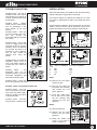
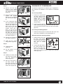
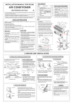
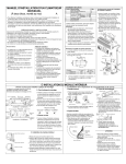
OFF
ROOM AIR
CONDITIONERS
This USER MANUAL is applicable for the
following ALASKA models :
Y9USC05-5A-F
Y9USC07-5A-F
Y9USC09-5A-F
Y9USE09-5A-F
Y9USC12-5A-F
Y9USE12-5A-F
Y9USC18-5A-F
Y9USE18-5A-F
Y9USC21-5A-F
USER MANUAL # 036 - 3007 TP (0206)
Y9USC24-5A-F
Y9USE24-5A-F
Y9UOC18-5A-F
Y9UOC24-5A-F
Y9UOC28-5A-F
Y9ROC18-5A-F
Y9ROC24-5A-F
Y9ROC28-5A-F
Y9ROH28-5A-F
ROOM AIR CONDITIONERS
CONTENTS
Electrical safety and rules ...............................................2
Power connections .......................................................... 2
Exploded view ................................................................. 2
Accessories ..................................................................... 2
Points to remember ......................................................... 3
Operating Instructions ..................................................... 3
Maintenance .................................................................... 5
Cleaning the air filter .......................................................5
Cleaning the front panel .................................................. 5
End of the season maintenance ...................................... 5
Trouble shooting..............................................................5
Installation .......................................................................6
Drainage condensed water ............................................. 7
ELECTRICAL SAFETY AND RULES
!
CAUTION
Â
ALL WIRING MUST COMPLY WITH LOCAL AND
NATIONAL ELECTRICAL CODES.
Â
WIRING SHOULD BE INSTALLED BY A QUALIFIED
ELECTRICIAN. IF YOU HAVE ANY QUESTIONS
REGARDING THE FOLLOWING INSTRUCTIONS,
CONTACT A QUALIFIED ELECTRICIAN.
Â
Â
NEVER INSERT YOUR FINGERS OR ANY FOREIGN
OBJECTS INTO THE AIR OUTLET. TAKE SPECIAL
CARE TO WARN CHILDREN OF THESE DANGERS.
TO AVOID THE POSSIBILITY OF PERSONAL INJURY,
BE SURE TO DISCONNECT POWER TO THE UNIT
BEFORE INSTALLING AND/OR SERVICING AND/OR
CLEANING.
Â
IF THE SUPPLY CORD IS DAMAGED, IT MUST BE
REPLACED BY THE MANUFACTURER OR ITS
SERVICE AGENT OR A PERSON NOMINATED BY ITS
AUTHORIZED DISTRIBUTOR IN ORDER TO AVOID A
HAZARD.
1.
The power cord is distinguished by the cord color as
shown in figure 1.
Figure 1
2.
3.
For your safety and protection, this unit is grounded
through the power cord plug when plugged into a
matching wall outlet (figure 2). Please contact the
manufacturer, its authorized distributor or service agent
if you want to replace it.
Figure 2
4.
Be sure that the unit being correctly grounded. The wall
outlet (air break switch) should be provided with reliable
earthing wire and should be accessible after installation.
5.
The unit should be provided with an individual branch
circuit and the fuse size should be same as that of the
power cord plug and wall outlet.
EXPLODED VIEW & ACCESSORIES
1. Front panel.
2. Air filter.
3. Frame.
4. Cabinet.
5. Air inlet for cooling condenser
coil.
6. Supply air grill.
7. Cover for controls (some
models only).
8. Power supply cord.
ACCESSORIES
Seal
Screws
(Wood)
1
8
Drain Plug
(Option)
Drain Pan
(Option)
Screws
(Front Panel)
For electrical power supply, see the specification on the
unit name plate.
IOM # 036 - 3007 TP (0206)
1
1
2
2
ROOM AIR CONDITIONERS
POINTS TO REMEMBER
1.
3 Minute Time Delay
If during the course of
operation, the unit is
turned off or, if the
operation
mode
is
changed from COOLING
to FAN ensure that the
unit remains in FAN
or
remain
MODE
switched off for at least three minutes before changing
the mode to COOLING once again.
2.
Remove Obstructions
Before switching the unit
on, make sure that the air
inlet grill and air outlet grill
are unobstructed.
4.
Operating Conditions
This units has been
designed
to
operate
efficiently in the following conditions :
Outdoor Temperature : 18°C to 45°C (’S’ Models) and
18°C to 56°C (’O’ Models)
Indoor Temperature : 18°C to 32°C
Heating Operation : Indoor Temperature -5°C to 30°C
Note : If the indoor relative humidity is more than 80%,
condensation may appear on the cabinet, the grills or at
other places on the body of the air conditioner.
Operation of the unit in ambient conditions higher than
the design conditions may cause the unit to trip or the
compressor may burn out.
5.
The operation panel will look like one of the following :
If you need to change the location of the unit, please
contact the York agent or distributor from whom you
have purchased the unit. The York agent or distributor
has trained personnel who can help you.
THERMOSTAT
AUTO LOUVER
SELECTOR
0
COOLER
ON
OFF
LOW
FAN
6
3
9
1
!
OFF
ON
OFF
HIGH
COOL
SELECTOR
AUTO SWING
THERMOSTAT
HIGH
FAN
LOW
COOL
TEST RUN
Attach The Air Filter
Before switching on the
air conditioner, make sure
that the air filter is
attached properly. If the
unit has not been used for
a long time, it is
recommended to clean
the air filter before your
using the unit. During continuous use, clean the air filter
at least once every two weeks.
3.
OPERATION PANEL - COOL ONLY
MODELS
HIGH
COOL
POWER
COOLER
MED
COOL
HIGH
FAN
LOW
FAN
LOW
COOL
CAUTION
WAIT AT LEAST 3 MINUTES BEFORE RESTARTING
OPERATING INSTRUCTIONS
OPERATING PANEL COVER
Depending on the model
purchased by you, your air
conditioner may not have a
cover on the operating panel.
Note : Do not swing or
press the open operating
panel cover.
X
OPERATION SELECTOR
To
set
desired
cooling
SELECTOR
temperature, simply rotate the
0
knob to the appropriate
setting. SELECTOR at HIGH
HIGH
LOW
FAN
FAN
FAN will circulate the air at a
maximum speed without a
cooling effect. At LOW FAN
LOW
HIGH
the unit will circulate the air at
COOL
COOL
a minimum speed without a
cooling effect. HIGH COOL
provides cooling, automatically with maximum air circulation.
LOW COOL provides cooling, automatically with minimum air
circulation. If the SELECTOR is positioned at ‘0’ the unit will
shut down.
Note : When turning the SELECTOR knob from LOW
COOL to HIGH COOL, keep the speed slow as far as
possible. Do not change the operation mode between
LOW COOL and HIGH COOL too often as the
compressor protection may trip the unit.
IOM # 036 - 3007 TP (0206)
3
ROOM AIR CONDITIONERS
THERMOSTAT
The thermostat automatically
starts and stops the running of
the compressor in the air
conditioner in order to control
and maintain a comfortable
room temperature. When the
room temperature reaches the
desired setting, cooling will
automatically stop. When the
temperature
rises
room
above, cooling resumes. This
results in efficient use of power and economical cooling.
model that you have purchased. While some differences
may be there in the appearance, the functions of the various
components are the same.
1
The operation is as follows : As the knob is turned towards
the right, the thermostat is set for a ‘COOLER’ temperature.
If the temperature becomes too cold, turn the knob towards
the left to set thermostat for warmer temperatures.
Note : TEST RUN is used to test the compressor and
make sure unit is working properly. When the knob is
rotated to this position, the unit is kept in cooling mode
and automatic temperature control is cut off. Do not use
this position for regular operation.
During the cooling operation of the unit, when the cooler
temperatures are required, wait at least three minutes,
otherwise the fuse may blow due to an overload of the
unit.
AUTO LOUVRE / AUTO SWING
Automatic horizontal air flow
adjustment : When the AUTO
LOUVER / AUTO SWING
switch is turned to ON
position, the vertical louvers
automatically oscillate left and
right sweeping the cold air
across the room to obtain
comfortable cooling.
CAUTION
When the switch is set to HIGH FAN or LOW FAN, the
air conditioner only blows air, without cooling or heating.
Knob should be turned slowly from LOW COOL or LOW
HEAT to HIGH COOL or HIGH HEAT.
When room temperature drops below 21°C and the unit
is in cooling operation, frost may form on the evaporator.
If this occurs, operate the air conditioner on the FAN
setting to defrost.
&
ELECTRIC
The operating panel will like on of the figures given below.
The design of the operation panel is based on the particular
IOM # 036 - 3007 TP (0206)
The function selection knob
controls fan speed and the
cooling speed. When it is set
to HIGH FAN a large volume of
air is discharged. When it is
set to LOW FAN, the volume if
air being discharged is
reduced. When it is set at
HIGH COOL fast cooling is
achieved. At LOW COOL the
cooling is relatively low.
!
Manual Vertical Air Flow
Adjustment : To adjust vertical
air flow direction, adjust any
one of the horizontal louver
blades. When turning the
blades
upwards
or
downwards, always keep the
top
or
bottom
blades
horizontal. This can effectively
prevent condensation of water
on the front panel of the unit.
(COOLING
Power indicator (selected models only) : This indicator
light remains on when the unit is on and goes off when the
SELECTOR is on OFF position.
At HIGH HEAT, rapid heating
takes place. At low heat, the
rate of heating is relatively
lower. At OFF, the air
conditioner remains switched
off. On FAN, only the fan runs
with no cooling or heating.
The vertical louvers may be
stopped at any position
(during oscillation) when the
AUTO LOUVER / AUTO
SWING switch is turned OFF .
OPERATION DETAILS
HEATING MODELS)
OFF
During cooling operation, if the thermostat knob has
been turned in the direction from ‘12’ to ‘1’, be sure to
wait at least three minutes before turning the knob back
toward ‘12’. Immediate turning of the knob may result in
a blown fuse
4
ROOM AIR CONDITIONERS
FRESH AIR VENTILATION
This is usually kept in the
closed position and is used
only when smoke and / or
odors are required to be
cleared from the room. When
the ventilation lever is pushed
to ‘CLOSE’, the fresh air
ventilation is closed, when the
ventilation is pushed to
‘OPEN’,
the
fresh
air
ventilation takes place.
Note: There is some difference
in the operation method
between different models. For
some models, when the
ventilation lever is pushed
forward,
the
fresh
air
ventilation is closed, when it is
pulled outward, the fresh air
ventilation is opened.
CLOSE
VENT
!
Â
AND
2.
Cleaning the Air Filter
Remove the dust clogged
in the filter by tapping it or
vacuum clean it. Wash
the filter well with lukewarm water or a neutral cleaning
agent.
3.
Cleaning the Air Freshener
The air freshener is fixed
on the reverse side of the
air filter, and should be
cleaned together with the
air filter.
Rinse the filter and
fresher well using clean
water. Allow time to dry
completely.
OPERATIONAL
CAUTION
TO AVOID THE POSSIBILITY OF INJURY, BE SURE
TO DISCONNECT POWER SUPPLY TO THE UNIT
BEFORE SERVICING AND / OR CLEANING.
Do
Not
use
gasoline,
benzene, thinner or any other
chemicals, or insecticide to
clean the air conditioner, as
these substances may cause
flaking off of the paint, and
cracking or deformation of
plastic parts.
Never attempt to clean the
unit by pouring water directly
over any of the surface areas,
as this will cause deterioration
of electrical components and
wiring insulation and it may
cause a short circuit or
electrocution.
CLEANING THE AIR FILTER
If the air filter becomes clogged with dust, air flow is
obstructed which reduces the cooling efficiency. The air filter
should be cleaned every two weeks.
IOM # 036 - 3007 TP (0206)
Remove Air Filter (See
Installation Instructions,
Step 1, on Page 7).
OPEN
Note : The VENTILATION LEVER should normally be
kept in the CLOSED position during cooling for
maximum cooling effect.
MAINTENAINCE
CARE
1.
4. Attaching the Air Filter
See Installation Instructions, Step 5, on Page 7.
Note : Never use hot water over 40°C (104°F) to clean
the air filter and air fresher. Never attempt to operate the
unit without the air filter.
CLEANING THE FRONT PANEL
During operation, dust may accumulate on the front panel,
use soft wet cloth with a neutral cleaning agent to wipe it.
Never use water over 50°C, alcohol, gasoline, acid, solvent
or brush to clean the front panel as this will damage the
surface.
END OF SEASON CARE
1.
2.
Operate the fan alone for half a day to dry out any
moisture from inside the
unit.
Turn off power and
remove plug from wall
outlet.
TROUBLE
SHOOTING
Problem : Unit is working, but cooling is not sufficient.
Possible Cause : It is quite
possible that the supply or
exhaust grill is blocked. This
prevents the unit from efficient
cooling.
Remove
any
obstructions.
Possible Cause : The outdoor
temperature
may
be
abnormally high due to the
unit being exposed to an
external source of heat.
5
ROOM AIR CONDITIONERS
TROUBLE SHOOTING
INSTALLATION
Possible Cause : The door or
windows of the room may be
open allowing hot outdoor air
to enter. Close all open doors
and windows.
Select the best location and install the unit at a place having
sufficient strength to support the unit securely.
For maximum efficiency, install the air conditioner on a side
of a house or building which offers more shade than direct
sunlight.
Possible Cause : Electric
heater, stove or water heater
may be operational in the
room. Switch off all such
devices.
Possible Cause : There are
too many people in the room.
You
can
change
the
thermostat setting to increase
the cooling.
Possible Cause : The air filter
could be clogged with dust
reducing air flow and cooling
efficiency of the unit. Remove
the air filter and clean it as
explained in this catalogue.
The air filter should be
cleaned once every two
weeks.
Provide sufficient clearance space around the air inlet and
outlet so that air flow will not be obstructed. Refer to the
figures given below for minimum clearance requirements :
D
Possible Cause : The fresh air
ventilation switch could be
open. This allows outside air
to enter the room. Close the
switch.
Possible
Cause
: The
thermostat may not be
adjusted properly. Check the
thermostat adjustment and
reset it at the proper value.
Size
(mm)
A
B
C
D
Less than 9000Btu/h More than 10000Btu/h
400
500
170
50
400
500
210
60
Step 1
Possible Cause : There may
be too many people in the rooms.
(a). Remove the front panel
and the air filter.
Problem : There is no air flow from the unit.
(b). Hold the slot under the
front panel, lift it onwards,
and remove the front
panel. (Figure 1)
Possible Cause : The unit
may not be working as there
may not be any power supply.
Check for proper connections
of the power cable.
Possible Cause : The fuse
may be blown. Check the fuse
Figure 1
(c). Pinch the handle under
the air filter. The air filter
will arch allowing easy
removal from the slot.
(Figure 2)
Step 2
Figure 2
(a). Remove the frame.
(b). Remove the two fixed
screws from the frame.
(Figure 3)
(c). Grasp the bottom left
corner of the frame to
loosen it. (Figure 4).
IOM # 036 - 3007 TP (0206)
Figure 3
6
ROOM AIR CONDITIONERS
Step 3
DRAINAGE OF CONDENSATE
(a). Remove the two fixed
screws on the chassis
fixing board, then remove
the chassis fixing board.
(Figure 5)
To meet the requirements of different type of applications,
two methods are available for the removal of condensate
water :
(b). Grasp the handle on the
chassis and carefully
slide the air conditioner
out of the cabinet. (Figure
6)
(c). If the condensed water
has to be drained, install
the drain tray behind the
cabinet and attach the
drain joint to the drain
hole at the back of the
chassis. Once this is
done, cut off the end
blockage. Make sure the
discharge mouth points to
the drain tray after the
chassis being pushed into
the cabinet. (Figure 7)
For cool only models
Figure 4
Figure 5
1.
If there is no need to drain
off water, seal the drain
hole at the bottom of the
cabinet with a rubber
stopper. This will increase
efficiency, but the noise
may be louder.
2.
If there is need to drain off
water, install the drain plug and connect the drain hose.
You may procure the drain hose from the local market.
(figure A)
Figure A
For Cooling and Heating Models
1.
Figure 6
(d). Push the unit chassis into
the cabinet. (Figure 8)
Install the drain plug and connect with drain hose. The
drain hose is available in local market (figure A)
Alternate method for draining off water
1.
Install the drain pan over
the area of the cabinet
from where the drain plug
was removed and secure
with
the
2
screws
provided.
2.
Connect the drain hose to
the outlet located at the
bottom of the drain pan.
You can purchase the
drain hose or tubing locally to satisfy your particular
needs (figure B) .
(e). Install the two chassis
fixing boards. (Figure 5)
Figure B
Step 4
(a). Install the frame.
(Figure 9)
Figure 7
(b). Fix the screws on the
frame. (Figure 3)
Step 5
(a). Install the air filter inside
the frame's slot moving it
from top towards the
bottom (Figure 2)
Figure 8
(b). Hang the front panel on
the frame buckle, then
press the front panel into
the frame slot until you
hear a click. (Figure 10)
Figure 9
Figure 10
IOM # 036 - 3007 TP (0206)
7
ROOM AIR CONDITIONERS
IOM # 036 - 3007 TP (0206)
8
Y9USC05-5A-F
Y9USC07-5A-F
Y9USC09-5A-F
Y9USE09-5A-F
Y9USC12-5A-F
Y9USE12-5A-F
Y9USC18-5A-F
Y9USE18-5A-F
Y9USC21-5A-F
Y9USC24-5A-F
Y9USE24-5A-F
Y9UOC18-5A-F
Y9UOC24-5A-F
Y9UOC28-5A-F
Y9ROC18-5A-F
Y9ROC24-5A-F
Y9ROC28-5A-F
Y9ROH28-5A-F