1
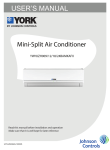
Split Air Conditioner
Thank you for choosing our product.
For proper operation, please read and keep this manual carefully.
T221S-H224-E
Operation Notices
Content
Precautions............................................................................................................1
Parts Name............................................................................................................6
Screen Operation Guide
Buttons on remote controller..................................................................................7
Introduction for icons on display screen.................................................................7
Introduction for buttons on remote controller.........................................................8
Introduction for special function............................................................................13
Operation guide................................................................................................... 15
Replacement of batteries in remote controller...................................................... 15
Emergency operation .......................................................................................... 16
Maintenance
Clean and Maintenance........................................................................................16
Malfunction
Malfunction analysis ............................................................................................19
Installation Notice
Installation dimension diagram ............................................................................23
Tools for installation .............................................................................................24
Selection of installation location .......................................................................... 24
Requirements for electric connection ..................................................................25
Installation
Installation of indoor unit......................................................................................26
Check after installation ........................................................................................31
Test and operation
Test operation ......................................................................................................31
Attachment
Configuration of connection pipe.........................................................................32
This appliance is not intended for use by persons (including children) with reduced physical, sensory
or mental capabilities, or lack of experience and knowledge, unless they have been given supervision
or instruction concerning use of the appliance by a person responsible for their safety.
Children should be supervised to ensure that they do not play with the appliance.
R410A(R32/125: 50/50): 1975
Precautions
WARNING
Operation and Maintenance
This appliance can be used by children aged from 8
years and above and persons with reduced physical,
sensory ormental capabilities or lack of experience and
knowledge if they have been given supervision or
instruction concerning use of the appliance in a safe
way and understand the hazards involved.
Children shall not play with the appliance.
Cleaning and user maintenance shall not be made by
children without supervision.
Do not connect air conditioner to multi-purpose socket.
Otherwise, it may cause fire hazard.
Do disconnect power supply when cleaning air
conditioner. Otherwise, it may cause electric shock.
.
If the supply cord is damaged, it must be replaced by
the manufacturer, its service agent or similarly qualified
persons in order to avoid a hazard.
Do not wash the air conditioner with water to avoid
electric shock.
Do not spray water on indoor unit. It may cause electric
shock or malfunction.
After removing the filter, do not touch fins to avoid injury.
Do not use fire or hair dryer to dry the filter to avoid
deformation or fire hazard.
1
Precautions
WARNING
Maintenance must be performed by qualified
professionals. Otherwise, it may cause personal injury
or damage.
Do not repair air conditioner by yourself. It may cause
electric shock or damage. Please contact dealer when
you need to repair air conditioner.
Do not extend fingers or objects into air inlet or air
outlet. It may cause personal injury or damage.
Do not block air outlet or air inlet. It may cause
malfunction.
Do not spill water on the remote controller, otherwise the
remote controller may be broken.
When below phenomenon occurs, please turn off air
conditioner and disconnect power immediately, and then
contact the dealer or qualified professionals for service.
● Power cord is overheating or damaged.
● There’s abnormal sound during operation.
● Circuit break trips off frequently.
● Air conditioner gives off burning smell.
● Indoor unit is leaking.
If the air conditioner operates under abnormal conditions,
it may cause malfunction, electric shock or fire hazard.
When turning on or turning off the unit by emergency
operation switch, please press this switch with an insulating
object other than metal.
Do not step on top panel of outdoor unit, or put heavy
objects. It may cause damage or personal injury.
2
Precautions
WARNING
Attachment
Installation must be performed by qualified professionals.
Otherwise, it may cause personal injury or damage.
Must follow the electric safety regulations when installing
the unit.
According to the local safety regulations, use qualified
power supply circuit and circuit break.
Do install the circuit break. If not, it may cause malfunction.
An all-pole disconnection switch having a contact separation
of at least 3mm in all poles should be connected in fixed
wiring.
Including an circuit break with suitable capacity, please
note the following table.Air switch should be included
magnet buckle and heating buckle function, it can protect
the circuit-short and overload.
Air Conditioner should be properly grounded. Incorrect
grounding may cause electric shock.
Don't use unqualified power cord.
Make sure the power supply matches with the
requirement of air conditioner.Unstable power supply or
incorrect wiring or malfunction. Please install proper power
supply cables before using the air conditioner.
Properly connect the live wire, neutral wire and
grounding wire of power socket.
Be sure to cut off the power supply before proceeding
any work related to electricity and safety.
3
Precautions
WARNING
Do not put through the power before finishing installation.
If the supply cord is damaged, it must be replaced by
the manufacturer, its service agent or similarly qualified
persons in order to avoid a hazard.
The temperature of refrigerant circuit will be high, please
keep the interconnection cable away from the copper
tube.
The appliance shall be installed in accordance with
national wiring regulations.
Installation must be performed in accordance with the
requirement of NEC and CEC by authorized personnel
only.
The air conditioner is the first class electric appliance. It
must be properly grounding with specialized grounding
device by a professional. Please make sure it is always
grounded effectively, otherwise it may cause electric shock.
The yellow-green wire in air conditioner is grounding
wire, which can't be used for other purposes.
The grounding resistance should comply with national
electric safety regulations.
The appliance must be positioned so that the plug is
accessible.
All wires of indoor unit and outdoor unit should be
connected by a professional.
If the length of power connection wire is insufficient, please
contact the supplier for a new one. Avoid extending the
wire by yourself.
4
Precautions
WARNING
For the air conditioner with plug, the plug should be
reachable after finishing installation.
For the air conditioner without plug, an circuit break
must be installed in the line.
If you need to relocate the air conditioner to another
place, only the qualified person can perform the work.
Otherwise, it may cause personal injury or damage.
Select a location which is out of reach for children and
far away from animals or plants.If it is unavoidable,
please add the fence for safety purpose.
The indoor unit should be installed close to the wall.
Working temperature range
Maximum cooling
Maximum heating
Indoor side DB/WB(℃/°F) Outdoor side DB/WB(℃/°F)
26.7/19.4(80/66.9)
46.1/23.9(115/75)
26.7/-(80/-)
23.9/18.3(75/64.9)
NOTICE:
● The operating temperature range (outdoor temperature) for cooling only unit is
-18℃(-0.4°F) ~ 46.1℃(115°F); for heat pump unit is -20℃(-4°F) ~ 46.1℃(115°F)
5
Parts Name
Indoor Unit
air inlet
panel
filter
aux.button
horizontal louver
cooling
indicator
power
indicator
air outlet
receiver
window
display
heating
indicator
temp.
indicator
drying
indicator
(Display content or position may be different from above
graphics, please refer to actual products)
NOTICE:
remote controller
Actual product may be different from above graphics, please refer to actual
products.
6
Buttons on remote controller
1 ON/OFF button
2 FAN button
3 MODE button
4 +/- button
5 TURBO button
6
button
2
2
5
4
11
3
9
1
13
6
4
3
8
10
12
14
16
7
7
8 CLOCK button
1
15
9 TIMER ON/
TIMER OFF button
10 TEMP button
11
(before opening cover
(after opening cover
button
/
button
12 I FEEL button
1 ON/OFF button
13 LIGHT button
2 FAN button
14 X-FAN button
3 MODE button
15 QUIET button
4 +/- button
16 SLEEP button
Introduction for icons on display screen
I feel
Quiet
Set fan speed
Turbo mode
Send signal
Healthy mode
Scavenging functions
8℃(46℉) heating function
Operation mode
Auto mode
Cool mode
Set temperature
X-FAN function
Dry mode
Fan mode
Heat mode
Set time
TIMER ON /TIMER OFF
Clock
Sleep mode
Child lock
Up & down swing
Left & right swing
Light
Temp. display type
: Indoor ambient temp.
: Outdoor ambient temp.
: Set temp.
7
Introduction for buttons on remote controller
Note:
● After putting through the power, the air conditioner will give out a sound.
Operation indictor " " is ON (red indicator). After that, you can operate the air
conditioner by using remote controller.
● Under on status, pressing the button on the remote controller, the signal icon " "
on the display of remote controller will blink once and the air conditioner will give
out a “de” sound, which means the signal has been sent to the air conditioner.
● Under off status, set temperature and clock icon will be displayed on the display
of remote controller (If timer on, timer off and light functions are set, the corresponding icons will be displayed on the display of remote controller at the same
time); Under on status, the display will show the corresponding set function icons.
1
ON/OFF button
2
FAN button
Press this button, the unit will be turned on, press it once more, the unit will be turned off. Sleep function will be canceled, while unit off.
Press this button, Auto, Low, Medium-low, Medium, Medium-high, High speed can
be circularly selected. After powered on, Auto fan speed is default. Under DRY
mode, Low fan speed only can be set up.
Note: It’s Low fan speed
under Dry mode.
ATUO
Low fan
3
Medium-low fan
Medium fan
Medium-high fan
High fan
MODE button
Press this button, Auto, Cool, Dry, Fan, Heat mode can be selected circularly. Auto
mode is default while power on. Under Auto mode, the temperature will not be displayed; Under Heat mode, the initial value is 28℃(82℉); Under other modes, the
initial value is 25℃(77 ℉).
AUTO
COOL
DRY
FAN
HEAT
(only for cooling and heating unit. As for cooling only unit, it won’t have any action
when it receives the signal of heating operation.)
4
+/- button
Presetting temperature can be increased. Press this button, the temperature can be
set up, continuously press this button and hold for two seconds, the relative contents
can quickly change, until unhold this button and send the order that the ℃(℉) signal
will be displayed all the time. The temperature adjustment is unavailable under the
Auto mode, but the order can be sent if pressing this button. Temperature of Celsius
degree setting: 16-30; for Fahrenheit degree setting: 61-86.
8
Introduction for buttons on remote controller
Presetting temperature can be decreased. Press this button, the temperature can
be set up, continuously press this button and hold for two seconds, the relative contents can quickly change, until unhold this button and send the order that the ℃
(℉) signal will be displayed all the time. The temperature adjustment is unavailable
under the Auto mode, but the order can be sent by if pressing this button.
5
TURBO button
Under Cool or Heat mode, press this button can turn on or turn off the Turbo function.
After the Turbo function turned on, the signal of Turbo will display. The signal will
be automatically cancelled if changing the mode or fan speed.
6
button
Press this button to set left & right swing angle cycling as below:
OFF
7
button
Press this button to set swing angle, which circularly changes as below:
OFF
This remote controller is universal. If it receives threes kinds of following status, the
swing angle will remain original.
If guide louver is stopped when it is swinging up and down, it will remian its present
position.
indicates guide louver swings back and forth in the five places, as shown in the figure.
8
CLOCK button
9
TIMER ON/TIMER OFF button
Press this button, the clock can be set up, signal blink and display. Within 5 seconds,
the value can be adjusted by pressing + or - button, if continuously press this button for 2
seconds above, in every 0.5 seconds, the value on ten place ofMinutewill be increased 1.
During blinking, repress the Clock button or Confirm button, signal will be constantly
displayed and it denotes the setting succeeded. After powered on, 12:00 is defaulted to
display and signal will be displayed. If there is signal be displayed that denotes
the current time value is Clock value, otherwise is Timer value.
Timer On setting: Sign al “ON” will blink and display, signal will conceal, the numerical section will become the timer on setting status. During 5 seconds blink, by
pressing + or - button to adjust the time value of numerical section, every press of
that button, the value will be increased or decreased 1 minute. Hold pressing + or -
9
Introduction for buttons on remote controller
button, 2 seconds later, it quickly change, the way of change is: During the initial
2.5 seconds, ten numbers change in the one place of minute, then the one place
is constant, ten numbers change in the tens place of minu te at 2.5 seconds speed
and carry. During 5s blink, press the Timer button, the timer setting succeeds. The
Timer On has been set up, repress the timer button, the Timer On will be canceled.
Before sett ing the Timer, please adjust the Clock to the current actual time.
One press this key to enter into TIMER OFF setup, in which case the TIMER OFF
icon will blink. The method of setting is the sameas for TIMER ON.
10
TEMP button
Press this button, you can see indoor set temperature, indoor ambient temperature
or outdoor ambient temperature on indoor unit’s display. The setting on remote controller is selected circularly as below:
no display
When selecting " " with remote controller or no display, temperature indicator on
indoor unit displays set temperature; When selecting " " with remote controller,
temperature indicator on indoor unit displays indoor ambient temperature; When
selecting " " with remote controller, temperature indicator on indoor unit displays
outdoor ambient temperature. 3s later it will return to the setting temprature or it
depends on the other received signal within 3s.
Attention: When displaying the outdoor ambient, the displaying range is 32-99℉
and 0-60 ℃.When it goes beyond the range, it keeps the threshold data (the smallest
—0℃ or 32℉ and the largest 99℉ or 60℃).
Warm tips: When operating buttons on the cover please make sure the cover is
closed completely.
11
/
button
Press this button to achieve the on and off of healthy and scavenging functions in
operation status. Press this button for the first time to start scavenging function;
LCD displays " ". Press the button for the second time to start healthy and scavenging functions simultaneously; LCD displays " " and " ". Press this button
for the third time to quit healthy and scavenging functions simultaneously. Press the
button for the fourth time to start healthy function; LCD display " ". Press this button again to repeat the operation above.
NOTE: This function is applicable to partial of models.
12
I FEEL button
Press this button once, to turn on the I FEEL function, then the figure of "I FEEL"
will be displayed, after every press of other function button, every 200ms to send
I FEEL once, after this function started, the remote controller will send temperature
to the main un it in every 10 minutes. When repress this button, this function will be
turned off.
10
Introduction for buttons on remote controller
13
LIGHT button
14
X-FAN button
15
QUIET button
16
SLEEP button
Press this button at unit On or Off status, Light On and Light Off can be set up.
After powered on, Light On is defaulted.
Pressing X-FAN button in COOL or DRY mode, the icon
is displayed and the
indoor fan will continue operation for 2 minutes in order to dry the indoor unit even
though you have turned off the unit. After energization, X-FAN OFF is defaulted.
X-FAN is not available in AUTO, FAN or HEAT mode.
Press this button, the Quiet status is under the Auto Quiet mode (display " "
and "Auto" signal) and Quiet mode (display " " singal) and Quiet OFF (there
is no signal of " " displayed), after powered on, the Quiet OFF is defaulted.
Under the Quiet mode (Display "
" signal).
Press this button, can select Sleep 1 (
), Sleep 2 (
), Sleep 3 (
) and
cancel the Sleep, circulate between these, after electrified, Sleep Cancel is defaulted.
Sleep 1 is Sleep mode 1, in Cool, Dehumidify modes: sleep status after run for
one hour, the main unit setting temperature will increase 1℃(1℉or 2℉) , 2 hours,
setting temperature increased 2℃(3℉or 4℉), the unit will run at this setting temperature;
In Heat mode: sleep status after run for one hour, the setting temperature will
decrease 1℃(1℉or 2℉) , 2 hours, setting temperature will decrease 2℃, then the unit
will run at this setting temperature.
Sleep 2 is sleep mode 2, that is air conditioner will run according to the presetting
a group of sleep temperature curve.
In Cool mode:
(1) When setting the initial temperature 16℃-23℃(61℉-74℉) , after turned on Sleep
function, the temperature will be increased 1 ℃ (1℉or 2℉) in every hour, after 3℃
(5℉or 6℉) the temperaturewill be maintained, after 7 hours, the temperature will
be decreased 1℃(1℉or 2℉), after that the unit will keep on running under this temperature;
(2) When setting the initial temperature 24℃-27℃(75℉-81℉), after turned on Sleep
function,the temperature will be increased 1℃(1℉or 2℉) in every hour, after 2℃
(5℉or 6℉) the temperature will be maintained, after 7hours, the temperature will
be decreased 1℃(1℉or 2℉) , after that the unit will keep on running under this temperature;
(3) When setting the initial temperature 28℃-29℃(82℉-85℉), after turned on Sleep
function,the temperature will be increased 1℃(1℉or 2℉) in every hour, after 1℃
(1℉or 2℉) the temperature will be maintained, after 7hours, the temperature will
be decreased 1℃(1℉or 2℉) , after that the unit will keep on running under this temperature;
11
Introduction for buttons on remote controller
(4) When setting the initial temperature 30℃(86℉), under this temperature setting,
after 7hours, the temperature will be decreased 1℃(1℉or 2℉) , after that the unit
will keep on running under this temperature;
In Heat mode:
(1) Under the initial presetting temperature 16℃(61℉) , it will run under this setting
temperature all along.
(2) Under the initial presetting temperature17℃-20℃(62℉-68℉) , after Sleep function
started up, the temperature will decrease 1℃(1℉or 2℉) in every hour, after
1℃(1℉or 2℉) decreased, this temperature will be maintained.
(3) Under the initial presetting temperature 21℃-27℃(69℉-81℉), after Sleep function
started up, the temperature will decrease 1℃(1℉or 2℉) in every hour, after 2℃
(3℉or 4℉) decreased, this temperature will be maintained.
(4) Under the initial presetting temperature 28℃-30℃(82℉-86℉), after Sleep function
started up, the temperature will decrease 1℃(1℉or 2℉) in every hour, after 3℃
(5℉or 6℉) decreased, this temperature will be maintained.
Sleep 3 - the sleep curve setting under Sleep mode by DIY:
(1) Under Sleep 3 mode, press "Turbo" button for a long time, remote controller enters into user individuation sleep setting status, at this time, the time of remote
controller will display "1hour", the setting temperature "88" will display the corresponding temperature of last setting sleep curve and blink (The first entering
will display according to the initial curve setting value of original factory);
(2) Adjust "+" and "-" button, could change the corresponding setting temperature,
after adjusted, press "Trubo" button for confirmation;
(3) At this time, 1hour will be automatically increased at the timer postion on the
remote controller, (that are "2hours" or "3hours" or "8hours"), the place of setting temperature "88" will display the corresponding temperature of last setting
sleep curve and blink;
(4) Repeat the above step (2)~(3) operation, until 8hours temperature setting finished,
sleep curve setting finished, at this time, the remote controller will resume the
original timer display; temperature display will resume to original setting temperature.
Sleep3 - the sleep curve setting under Sleep mode by DIY could be inquired:
The user could accord to sleep curve setting method to inquire the presetting sleep
curve, enter into user individuation sleep setting status, but do not change the temperature, press "Turbo" button directly for confirmation.
Note: In the above presetting or enquiry procedure, if continuously within10s, there
is no button pressed, the sleep curve setting status will be automatically quit
and resume to display the original displaying. In the presetting or enquiry procedure, press "ON/OFF" button, "Mode" button, "Timer" button or "Sleep"
button, the sleep curve setting or enquiry status will quit similarly.
12
Introduction for special function
About X-FAN function
This function indicates that moisture on evaporator of indoor unit will be blowed after
the unit is stopped to avoid mould.
1. Having set X-FAN function on: After turning off the unit by pressing ON/OFF button
indoor fan will continue running for about 2 min. at low speed. In this period, press
X-FAN button to stop indoor fan directly.
2. Having set X-FAN function off: After turning off the unit by pressing ON/OFF button,
the complete unit will be off directly.
About AUTO RUN
When AUTO RUN mode is selected, the setting temperature will not be displayed on
the LCD, the unit will be in accordance with the room temp. automatically to select the
suitable running method and to make ambient comfortable.
About turbo function
If start this function, the unit will run at super-high fan speed to cool or heat quickly so
that the ambient temp. approachs the preset temp. as soon as possible.
About lock
Press + and - buttons simultaneously to lock or unlock the keyboard. If the remote controller is locked, the icon
will be displayed on it, in which case, press any button,
the mark will flicker for three times. If the keyboard is unlocked, the mark will disappear.
About swing up and down
1. Press swing up and down button continuously more than 2s, the m ain unit will swing
backand forth from up to down , and then loosen the button, the unit will stop swing
and present position of guide louver will be kept immediately.
2. Under swing up and down mode, when the status is switched from off to
, if press
this button again 2s later,
status will switch to off status directly; If press this button
again within 2s, the change of swing status will also depend on the circulation sequence stated above.
About swing left and right
1. Press swing left and right button continuously more than 2s, the main unit will swing
back and forth from left to right, and then loosen the button, the unit will stop swing
and present position of guide louver will be kept immediately.
2. Under swing left and right mode, when the status is switched from off to
, if press
this button again 2s later,
status will switch to off status directly; if press this button
again within 2s, the change of swing status will also depend on the circulation sequence stated above.
13
Introduction for special function
About switch between Fahrenheit and Centigrade
Under status of unit off, press MODE and - buttons simultaneously to switch ℃ and ℉.
Combination of "TEMP" and "CLOCK" buttons:
About Energy - saving Function
Press “TEMP” and “CLOCK” simultaneously in COOL mode to start energy-saving function. Nixie tube on the remote controller displays “SE”. Repeat the operation to quit
the function.
Combination of "TEMP" and "CLOCK" buttons:
About 8℃(46℉) Heating Function
Press “TEMP” and “CLOCK” simultaneously in HEAT mode to start 8℃ 46℉ Heating Function Nixie tube on the remote controller displays “ ” and a selected temperature of “8℃”.
(46℉ if Fahrenheit is adopted). Repeat the operation to quit the function.
About auto Quiet function
When quiet function is selected:
1. Under cooling mode: indoor fan operates at notch 4 speed. 10 minutes later or when
indoor ambient temperature≤28℃(82℉) , indoor fan will operate at notch 2 speed or
quiet mode according to the comparison between indoor ambinet temperature and set
temperature.
2. Under heating mode: indoor fan operates at notch 3 speed or quiet mode according
to the comparison between indoor ambient temperature and set temperature.
3. Under dry, fan mode: indoor fan operates at quiet mode.
4. Under auto mode: the indoor fan operates at the auto quiet mode according to actual
cooling, heating or fan mode.
About Sleep function
Under the Fan and Auto mode, the Sleep function cannot be set up, under Dehumidify
mode, only Sleep 1 can be selected. Select and enter into any kind of Sleep mode, the
Quiet function will be attached and stared, different Quiet status could be optional and
turned off.
14
Operation guide
General operation
4
1. After powered on, press ON/OFF button, the unit will start
to run. (Note: When it is powered on, the guide louver of
main unit will close automatically.)
2. Press MODE button, select desired running mode.
3. Pressing + or - button, to set the desired temperature (It is
unnecessary to set the temp. at AUTO mode.)
4. Pressing FAN button, set fan speed, can select AUTO FAN,
LOW, MEDIUM-LOW, MEDIUM, MEDIUM-HIGH and HIGH.
5. Pressing and button, to select the swing.
Optional operation
1. Press SLEEP button, to set sleep.
2. Press TIMER ON and TIMER OFF button, can set the
scheduled timer on or timer off.
3. Press LIGHT button, to control the on and off of the
displaying part of the unit (This function may be not
available for some units).
4. Press TURBO button, can realize the ON and OFF of
TURBO function.
3
5
2
1
4
2
1
3
Replacement of batteries in remote controller
1. Press the back side of remote controller marked
the cover of battery box along the arrow direction.
2. Replace two 7# (AAA 1.5V) dry batteries, and
make sure the position of "+" polar and "-" polar
are correct.
3. Reinstall the cover of battery box.
battery
reinstall
remove
Cover of battery box
Note:
● During operation, point the remote control signal sender at the receiving
window on indoor unit.
● The distance between signal sender and receiving window should be no
more than 8m, and there should be no obstacles between them.
● Signal may be interfered easily in the room where there is fluorescent lamp
or wireless telephone; remote controller should be close to indoor unit during
operation.
● Replace new batteries of the same model when replacement is required.
● When you don’t use remote controller for a long time, please take out the
batteries.
● If the display on remote controller is fuzzy or there’s no display, please
replace batteries.
15
Emergency operation
If remote controller is lost or damaged, please use auxiliary button to turn
on or turn off the air conditioner. The operation in details are as below:
air conditioner. When the air conditioner is turned on, it will operate under
auto mode.
panel
aux. button
WARNING:Use insulated object
to press the auto button
Clean and Maintenance
WARNING
■ Turn off the air conditioner and disconnect the power before cleaning the air
conditioner to avoid electric shock.
■ Do not wash the air conditioner with water to avoid electric shock.
■ Do not use volatile liquid to clean the air conditioner.
Clean surface of indoor unit
When the surface of indoor unit is dirty, it is recommended to use a soft dry cloth
or wet cloth to wipe it.
NOTICE:
● Do not remove the panel when cleaning it.
16
Clean and Maintenance
1
Open panel
3
Pull out the panel to a certain
● Use dust catcher or water to
the water (below 45℃(113℉))
to clean it, and then put it in
a shady and cool place
. to dry
2
4
panel cover tightly.
WARNING
operation environment, clean frequency can be increased.
17
Clean and Maintenance
NOTICE: Checking before use-season
1. Check whether air inlets and air outlets are blocked.
2. Check whether air switch, plug and socket are in good condition.
3. Check whether filter is clean.
4. Check whether mounting bracket for outdoor unit is damaged or corroded.
If yes, please contact dealer.
5. Check whether drainage pipe is damaged.
NOTICE: Checking after use-season
1. Disconnect power supply.
2. Clean filter and indoor unit’s panel.
3. Check whether mounting bracket for outdoor unit is damaged or corroded.
If yes, please contact dealer.
Notice for recovery
1. Many packing materials are recyclable materials.
Please dispose them in appropriate recycling unit.
2. If you want to dispose the air conditioner, please contact local dealer or
consultant service center for the correct disposal method.
18
Malfunction analysis
General phenomenon analysis
Please check below items before asking for maintenance. If the malfunction still
can’t be eliminated, please contact local dealer or qualified professionals.
Phenomenon
Check items
Solution
● Whether it's interfered severely ● Pull out the plug. Reinsert
(such as static electricity, stable the plug after about 3min, and
voltage)?
then turn on the unit again.
Indoor unit
can’t receive
remote
controller’s
signal or
remote
controller
has no
action.
● Whether remote controller is
within the signal receiving
range?
● Signal receiving range is 8m.
● Whether there are obstacles?
● Remove obstacles.
● Whether remote controller is
● Select proper angle and point
pointing at the receiving
the remote controller at the rewindow?
ceiving window on indoor unit.
● Is sensitivity of remote contro- ● Check the batteries. If the
ller low; fuzzy display and no
power of batteries is too low,
display?
please replace them.
● Check whether remote cont● No display when operating
roller appears to be damaged.
remote controller?
If yes, replace it.
● Fluorescent lamp in room?
No air
emitted
from
indoor
unit
● Take the remote controller
close to indoor unit.
● Turn off the fluoresent lamp
and then try it again.
● Air inlet or air outlet of indoor
unit is blocked?
● Eliminate obstacles.
● Under heating mode, indoor
temperature is reached to set
temperature?
● After reaching to set temperature, indoor unit will stop blowing out air.
● Heating mode is turned on just ● In order to prevent blowing
now?
out cold air, indoor unit will be
started after delaying for several minutes, which is a normal phenomenon.
19
Malfunction analysis
Phenomenon
Air conditioner can’t
operate
Mist is emitted from
indoor unit’s
air outlet
Set temperature can’t
be adjusted
Cooling
(heating)
effect is
not good.
Check items
Solution
● Power failure?
● Wait until power recovery.
● Is plug loose?
● Reinsert the plug.
● Air switch trips off or fuse is
burnt out?
● Ask professional to replace
air switch or fuse.
● Wiring has malfunction?
● Ask professional to replace it.
● Unit has restarted immediately
● Wait for 3min, and then turn
after stopping operation?
on the unit again.
● Whether the function setting
for remote controller is
correct?
● Reset the function.
● Indoor temperature and humidity is high?
● Because indoor air is cooled
rapidly. After a while, indoor
temperature and humidity will
be decrease and mist will
disappear.
● Unit is operating under auto
mode?
● Temperature can’t be adjusted under auto mode.
Please switch the operation
mode if you need to adjust
temperature.
● Your required temperature
exceeds the set temperature
range?
● Set temperature range:
16℃ ~30℃(61℉-86℉) .
● Voltage is too low?
● Wait until the voltage
resumes normal.
● Filter is dirty?
● Clean the filter.
● Set temperature is in proper
range?
● Adjust temperature to proper
range.
● Door and window are open?
● Close door and window.
20
Malfunction analysis
Phenomenon
Odours are
emitted
Check items
Solution
● Whether there’s odour source, ● Eliminate the odour source.
such as furniture and cigarette,
etc.
Air conditioner ● Whether there’s interference,
such as thunder, wireless
operates
devices, etc.
abnormally
Outdoor
unit has
vapor
“Water
noise
Cracking
noise
● Heating mode is turned on?
● Air conditioner is turned on or
turned off just now?
● Air conditioner is turned on or
turned off just now?
21
● Disconnect power, put back
power, and then turn on the
unit again.
● During defrosting under heating mode, it may generate
vapor, which is a normal
phenomenon.
● The noise is the sound of
the unit, which is a normal
phenomenon.
● This is the sound of friction
caused by expansion and/or
contraction of panel or other
parts due to the change of
temperature.
Malfunction analysis
Error Code
● When air conditioner status is abnormal, temperature indicator on indoor unit will
ation of error code.
Indoor
display
Error code
Above indicator diagram is only
for reference. Please refer to
actual product for the actual
indicator and position.
Error code
Troubleshooting
Heating indicator
ON 10s OFF 0.5s
Means defrosting status. It’s the normal phenomenon.
F1
Please contact qualified professionals for service.
F2
Please contact qualified professionals for service.
C5
Please contact qualified professionals for service.
H6
It can be eliminated after restarting the unit. If not, please
contact qualified professionals for service.
It can be eliminated after restarting the unit. If not, please
E5
Note: If there're other error codes, please contact qualified professionals for
service.
WARNING
■ When below phenomenon occurs, please turn off air conditioner and disconfor service.
● Power cord is overheating or damaged.
● There’s abnormal sound during operation.
● Air switch trips off frequently.
● Air conditioner gives off burning smell.
● Indoor unit is leaking.
■ If the air conditioner operates under abnormal conditions, it may cause
22
At least 15cm
Space to the ceiling
Installation dimension diagram
Space to the wall
At least 15cm
At least 15cm
Space to the wall
S
he
ot
et
c
pa
le
m
0c
30
n
ctio
tru
s
ob
At least 250cm
At
t
as
23
Tools for installation
1 Level meter
2 Screw driver
3 Impact drill
4 Drill head
5 Pipe expander
6 Torque wrench
7 Open-end wrench
8 Pipe cutter
9 Leakage detector
10 Vacuum pump
11 Pressure meter
12 Universal meter
13 Inner hexagon spanner
Note:
14 Measuring tape
● Please contact the local agent for installation.
● Don't use unqualified power cord.
Selection of installation location
Basic requirement
Installing the unit in the following places maycause malfunction. If it is unavoidable, please consult the local
dealer:
1.The place with strong heat sources,
,
or volatile objects spread in the air.
2.The place with high-frequency
devices (such as welding machine,
medical equipment).
3.The place near coast area.
4.The place with oil or fumes in the air.
5.The place with sulfureted gas.
6.Other places with special circumstances.
7.The appliance shall not be installed in the laundry.
Outdoor unit
Indoor unit
1. There should be no obstruction near air
inlet and air outlet.
2. Select a location where the condensation water can be dispersed easily and
won't affect other people.
3. Select a location which is convenient to
connect the outdoor unit and near the
power socket.
4. Select a location which is out of reach
for children.
5. The location should be able to withstand
the weight of indoor unit and won't increase noise and vibration.
6. The appliance must be installed 2.5m
7. Don't install the indoor unit right above
the electric appliance.
8. Please try your best to keep way from
fluorescent lamp.
will not affect neighborhood.
2. The location should be well ventilated and dry, in which the outdoor unit
won't be exposed directly to sunlight or strong wind.
3. The location should be able to withstand the weight of outdoor unit.
4. Make sure that the installation follows the requirement of installation
dimension diagram.
5. Select a location which is out of reach for children and far away from animals
or plants.If it is unavoidable, please add the fence for safety purpose.
24
Requirements for electric connection
Safety precaution
1. Must follow the electric safety regulations when installing the unit.
air switch.
3. Make sure the power supply matches with the requirement of air conditioner.
Unstable power supply or incorrect wiring or malfunction. Please install proper
power supply cables before using the air conditioner.
4. Properly connect the live wire, neutral wire and grounding wire of power socket.
5. Be sure to cut off the power supply before proceeding any work related to
electricity and safety.
7. If the supply cord is damaged, it must be replaced by the manufacturer, its
8. The temperature of refrigerant circuit will be high, please keep the interconnection cable away from the copper tube.
9. The appliance shall be installed in accordance with national wiring regulations.
Grounding requirement
grounding with specialized grounding device by a professional. Please make
sure it is always grounded effectively, otherwise it may cause electric shock.
2. The yellow-green wire in air conditioner is grounding wire, which can't be used
for other purposes.
3. The grounding resistance should comply with national electric safety regulations.
4. The appliance must be positioned so that the plug is accessible.
5. An all-pole disconnection switch having a contact separation of at least 3mm in
25
Installation of indoor unit
Step one: choosing installation location
rm it with the client.
Step two: install wall-mounting frame
1. Hang the wall-mounting frame on the wall; adjust it in horizontal position with the
plastic expansion particles in the holes.
3. Fix the wall-mounting frame on the wall with tapping screws (ST4.2X25TA) and
.
Step three: open piping hole
1. Choose the position of piping hole according to the direction of outlet pipe. The
position of piping hole should be a little lower than the wall-mounted frame,
shown as below.
09、12K:
Wall
Space
to the
wall
above
150mm
Mark in the middle of it
Level meter
Right
Φ55mm
Rear piping hole
Left
Φ55mm
Rear piping hole
18K:
Wall
Space
to the
wall
above
150mm
Wall
Space
to the
wall
above
150mm
24K:
Mark in the middle of it
Left
Φ70mm
Rear piping hole
Level meter
Wall
Wall
Space
to the
wall
above
150mm
Space
to the
wall
above
150mm
Right
Φ70mm
Rear piping hole
Mark in the middle of it
Left
Φ70mm
Rear piping hole
Level meter
Wall
Space
to the
wall
above
150mm
Right
Φ70mm
Rear piping hole
2. Open a piping hole with the diameter of Φ55/Φ70 on the selected outlet pipe
position. In order to drain smoothly, slant the piping hole on the wall slightly
downward to the outdoor side with the gradient of 5-10°.
26
Installation of indoor unit
Indoor
outdoor
Note:
● Pay attention to dust prevention and
take relevant safety measures when
opening the hole.
● The plastic expansion particles are
not provided and should be bought
locally.
Φ55/
Φ70
5-10
Step four: outlet pipe
2. When select leading out the pipe
from left or right, please cut off the
corresponding hole on the bottom
case.
1. The pipe can be led out in the
direction of right, rear right, left or
rear left.
right
left
right
left
rear right
rear left
cut off
the hole
1. Aim the pipe joint at the corresponding
bellmouth.
pipe joint
union nut
pipe
2. Pretightening the union nut with hand.
3. Adjust the torque force by referring to the following sheet. Place the open-end
wrench on the pipe joint and place the torque wrench on the union nut. Tighten
the union nut with torque wrench.
27
Installation of indoor unit
open-end
wrench
union nut
torque wrench
pipe
Hex nut diameter Tightening torque (N.m)
Φ6
15~20
Φ 9.52
30~40
Φ 12
45~55
Φ 16
60~65
Φ 19
70~75
indoor pipe
4. Wrap the indoor pipe and joint of connection pipe with insulating pipe, and
then wrap it with tape.
insulating pipe
Step six: install drain hose
1. Connect the drain hose to the outlet pipe of
indoor unit.
2. Bind the joint with tape.
outlet pipe
drain hose
drain hose
outlet
pipe
tape
drain hose
Note:
● Add insulating pipe in the indoor
drain hose in order to prevent
condensation.
● The plastic expansion particles are
not provided.
insulating pipe
Step seven: connect wire of indoor unit
panel
screw
1. Open the panel, remove the screw
on the wiring cover and then take
down the cover.
28
wiring cover
Installation of indoor unit
2. Make the power connection wire go
through the cable-cross hole at the back
of indoor unit and then pull it out from
the front side.
cable-cross
hole
power connection
wire
3. Remove the wire clip; connect the power
connection wire to the wiring terminal
according to the color; tighten the screw
with wire clip.
N(1)
2
3
N(1)
2
3
outdoor unit connection
4. Put wiring cover back and then tighten the screw.
5. Close the panel.
Notice before installation
1. How to install the over line pipe(According to the direction as show.)
Screw
wire pipe
Fixed nut
Note:
● All wires of indoor unit and outdoor unit should be connected by a professional.
for a new one. Avoid extending the wire by yourself.
installation.
● For the air conditioner without plug, an air switch must be installed in the line.
The air switch should be all-pole parting and the contact parting distance should
be more than 3mm.
29
Installation of indoor unit
Step eight: bind up pipe
1. Bind up the connection pipe, power
cord and drain hose with the band.
indoor unit
gas
pipe
connection pipe
drain hose
band
indoor and
outdoor power cord
indoor power cord
band
3. Bind them evenly.
4. The liquid pipe and gas pipe should
be bound separately at the end.
liquid pipe
drain hose
2. Reserve a certain length of drain
hose and power cord for installation
when binding them. When binding to
a certain degree, separate the indoor
power and then separate the drain
hose.
Note:
● The power cord and control wire
can't be crossed or winding.
● The drain hose should be bound
at the bottom.
Step nine: hang the indoor unit
1. Put the bound pipes in the wall pipe and then make them pass through the wall
hole.
2. Hang the indoor unit on the wall-mounting frame.
3. Stuff the gap between pipes and wall hole with sealing gum.
4. Fix the wall pipe.
5. Check if the indoor unit is installed firmly and closed to the wall.
indoor
wall pipe
upper hook
outdoor
sealing gum
lower hook of
wall-mounting frame
Note:
● Do not bend the drain hose too excessively in order to prevent blocking.
30
Check after installation
● Check according to the following requirement after finishing installation.
Items to be checked
Possible malfunction
Has the unit been installed firmly?
The unit may drop, shake or emit noise.
Have you done the refrigerant leakage
test?
It may cause insufficient cooling
(heating) capacity.
Is heat insulation of pipeline sufficient?
It may cause condensation and water
dripping.
Is water drained well?
It may cause condensation and water
dripping.
Is the voltage of power supply according to the voltage marked on the
nameplate?
It may cause malfunction or damaging
the parts.
Is electric wiring and pipeline installed
correctly?
It may cause malfunction or damaging
the parts.
Is the unit grounded securely?
It may cause electric leakage.
Does the power cord follow the specification?
It may cause malfunction or damaging
the parts.
Is there any obstruction in the air inlet
and outlet?
It may cause insufficient cooling
(heating) capacity.
The dust and sundries caused during
installation are removed?
It may cause malfunction or damaging
the parts.
The gas valve and liquid valve of
connection pipe are open completely?
It may cause insufficient cooling
(heating) capacity.
Test operation
1. Preparation of test operation
● The client approves the air conditioner.
● Specify the important notes for air conditioner to the client.
2. Method of test operation
● Put through the power, press ON/OFF button on the remote controller to start
operation.
● Press MODE button to select AUTO, COOL, DRY, FAN and HEAT to check
whether the operation is normal or not.
● If the ambient temperature is lower than 16℃( )
61℉ , the air conditioner can’t
start cooling.
31
Configuration of connection pipe
1. Standard length of connection pipe
● 5m, 7.5m, 8m.
2.Min. length of connection pipe is 3m.
3.Max. length of connection pipe and max. high difference.
Cooling
capacity
Max length
Max height
of connecdifference
tion pipe
Cooling
capacity
Max length
Max height
of connecdifference
tion pipe
5000Btu/h
(1465W)
15
5
24000Btu/h
(7032W)
25
10
7000Btu/h
(2051W)
15
5
28000Btu/h
(8204W)
30
10
9000Btu/h
(2637W)
15
5
36000Btu/h
(10548W)
30
20
12000Btu/h
(3516W)
20
10
42000Btu/h
(12306W)
30
20
18000Btu/h
(5274W)
25
10
48000Btu/h
(14064W)
30
20
4. The additional refrigerant oil and refrigerant charging required after prolonging
connection pipe
● After the length of connection pipe is prolonged for 10m at the basis of
standard length, you should add 5ml of refrigerant oil for each additional 5m
of connection pipe.
● The calculation method of additional refrigerant charging amount (on the basis
of liquid pipe):
Additional refrigerant charging amount = prolonged length of liquid pipe ×
additional refrigerant charging amount per meter
● Basing on the length of standard pipe, add refrigerant according to the
requirement as shown in the table. The additional refrigerant charging amount
per meter is different according to the diameter of liquid pipe. See the
following sheet.
32
Configuration of connection pipe
Additional refrigerant charging amount for R22, R407C, R410A and R134a
Diameter of connection pipe
Outdoor unit throttle
Liquid pipe(mm)
Gas pipe(mm)
Cooling only(g/m) Cooling and heating(g/m)
Φ6
Φ9.52 or Φ12
15
20
Φ6 or Φ9.52
Φ16 or Φ19
15
50
Φ12
Φ19 or Φ22.2
30
120
Φ16
Φ25.4 or Φ31.8
60
120
Φ19
_
250
250
Φ22.2
_
350
350
33
LIMITED WARRANTY
T-1 SERIES DUCTLESS SYSTEMS
THERMOCORE SYSTEMS (THERMOCORP INC) warrants
that the condensing unit and evaporator conforms to the
manufacturers specifications and will be free of defects in
material and workmanship under normal use and
maintenance as listed and described below:
THERMOCORE SYSTEMS is not responsible for:
1. Damage as a result of flood, fire, lighting, accidents, corrosive
atmosphere or other conditions beyond our control.
2. Damage or repairs performed as a result of faulty installation
or application of product.
- To the original registered owner and his/her spouse all
parts are warranted for a period of one (1) year from the
date of purchase except as provided below:
- To the original registered owner and his/her spouse, the
compressor is warranted for a period of five (5) years from
the date of purchase except as provided below.
The responsibility of THERMOCORE SYSTEMS to this
warranty is to furnish a replacement part (without
charge) that has been confirmed to be defective due to
fault in workmanship or materials and complies with
below stipulations.
3. Normal maintence as described in operational manual such as
cleaning / replacing filters, lubrication, cleaning of coils etc.
4. Use of components and or accessories not compatible or
intended for use with system.
5. System failures due to interruption or inadequate electrical
services or electrical spikes from local utilities.
6. Damage or repairs caused by improper use, maintenance,
operation or servicing.
WARRANTY REGISTRATION
CARD:
Owners Name:
Address of Installation:
1. To obtain warranty service, your dealer or contractor who
City:
installed this product must be a qualified HVAC contractor
Phone#:
and available for consultation to troubleshoot the
Installers Name:
merchandise from the job site to be sure proper diagnostic is
obtained.
2. Warranty service does not continue after the unit is
removed from the location where it was originally installed.
Address:
City:
Phone#:
3. Any defective part to be replaced must be made available
Invoice ID:
to THERMOCORE SYSTEMS in exchange for the
Indoor Model#
replacement part. You must present proof of the original date
Indoor Serial#
went into effect. (such as an installation invoice). Otherwise
the effective date will be deemed to be date of delivery plus
State:
Outdoor Model#
Outdoor Serial#
four-teen (14) days.
Date of Purchase:
4. This warranty does not cover any labor, freight or any
Signature of Owner:
other costs associated with repair, replacement, service or
Signature of Installer:
operation of system.
Please sign and fax back to: 866-775-9620
5. This warranty applies only if the unit is installed and
Thermocorp INC
operated in accordance with THERMOCORE SYSTEMS
Zip:
License#
(Except with mobile homes)
of installation in order to establish when the warranty package
State:
Date of Install:
13000 Capital St. Oak Park, MI 48237
instructions and in compliance with applicable local
www.thermocoresystems.com
installation building codes and good trade practices.
855-382-8110 / 248-918-0619
Zip:
66129917228