1
ACZCI
4H4R18
ACZEM4H4R18
ACZCI
4H4R24
ACZEM4H4R24
Content
Operation Notices
Precautions............................................................................................................1
Parts name ............................................................................................................2
Screen Operation Guide
Buttons on remote controller .................................................................................3
Introduction for icons on display screen ................................................................3
Introduction for buttons on remote controller.........................................................4
Function introduction for combination buttons.......................................................6
Operation guide .....................................................................................................7
Replacement of batteries in remote controller.......................................................7
Emergency operation ............................................................................................8
Maintenance
Clean and maintenance.........................................................................................8
Malfunction
Malfunction analysis ............................................................................................ 11
Installation Notice
Installation dimension diagram ............................................................................15
Tools for installation .............................................................................................16
Selection of installation location ..........................................................................16
Requirements for electric connection ..................................................................17
Installation
Installation of indoor unit......................................................................................18
Installation of outdoor unit ...................................................................................23
Vacuum pumping.................................................................................................26
Leakage detection ...............................................................................................26
Check after installation ........................................................................................27
Test and operation
Test operation ......................................................................................................27
Attachment
&RQ¿JXUDWLRQRIFRQQHFWLRQSLSH .........................................................................28
Pipe expanding method.......................................................................................30
This appliance is not intended for use by persons (including children) with reduced physical, sensory
or mental capabilities or lack of experience and knowledge, unless they have been given supervision
or instruction concerning use of the appliance by a person responsible for their safety.
Children should be supervised to ensure they are away from the appliance.
Do not dispose this product as unsorted municipal waste. Collection of
such waste separately for special treatment is necessary.
Precautions
Warning
Ɣ'RQRWFRQQHFWDLUFRQGLWLRQHUWRPXOWLSXUSRVHVRFNHW 2WKHUZLVHLWPD\
FDXVH¿UHKD]DUG
Ɣ'RGLVFRQQHFWSRZHUVXSSO\ZKHQFOHDQLQJDLUFRQGLWLRQHU2WKHUZLVHLWPD\
cause electric shock.
Ɣ'RQRWVSUD\ZDWHURQLQGRRUXQLW,WPD\FDXVHHOHFWULFVKRFNRUPDOIXQFWLRQ
Ɣ'RQRWVSLOOZDWHURQWKHUHPRWHFRQWUROOHURWKHUZLVHWKHUHPRWHFRQWUROOHU
may be broken.
Ɣ'RQRWUHSDLUDLUFRQGLWLRQHUE\\RXUVHOI,WPD\FDXVHHOHFWULFVKRFNRU
damage. Please contact dealer when you need to repair air conditioner.
Ɣ'RQRWEORFNDLURXWOHWRUDLULQOHW,WPD\FDXVHPDOIXQFWLRQ
Ɣ,I\RXQHHGWRUHORFDWHWKHDLUFRQGLWLRQHUWRDQRWKHUSODFHRQO\WKHTXDOL¿HG
person can perform the work. Otherwise, it may cause personal injury or
damage.
Ɣ'RQRWVWHSRQWRSSDQHORIRXWGRRUXQLWRUSXWKHDY\REMHFWV,WPD\FDXVH
damage or personal injury.
Ɣ'RQRWH[WHQG¿QJHUVRUREMHFWVLQWRDLULQOHWRUDLURXWOHW,WPD\FDXVH
personal injury or damage.
Ɣ$LU&RQGLWLRQHUVKRXOGEHSURSHUO\JURXQGHG,QFRUUHFWJURXQGLQJPD\FDXVH
electric shock.
Ɣ'RLQVWDOOWKHFLUFXLWEUHDN,IQRWLWPD\FDXVHPDOIXQFWLRQ
Ɣ,QVWDOODWLRQDQGPDLQWHQDQFHPXVWEHSHUIRUPHGE\TXDOL¿HGSURIHVVLRQDOV
Otherwise, it may cause personal injury or damage.
Working temperature range
Maximum cooling
Maximum heating
Indoor side DB/WB(ć )
32/23
27/-
Outdoor side DB/WB(ć )
43/26
24/18
Ɣ7KHRSHUDWLQJWHPSHUDWXUHUDQJHRXWGRRUWHPSHUDWXUHIRUFRROLQJRQO\XQLWLV
18ć ~43ć ; for heat pump unit is -7ć ~ 43ć .
1
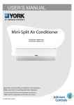
Parts name
Indoor Unit
air inlet
panel
¿OWHU
aux.button
KRUL]RQWDOORXYHU
air outlet
cooling
indicator
power
indicator
receiver
window
display
heating
indicator
temp.
indicator
drying
indicator
remote control
(Display content or position may be different from above
graphics, please refer to actual products)
Outdoor Unit
air inlet
handle
air outlet
Notice:
$FWXDOSURGXFWPD\EHGLIIHUHQWIURPDERYHJUDSKLFVSOHDVHUHIHUWRDFWXDO
products.
2
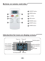
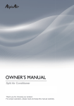
Buttons on remote controller
1 ON/OFF button
1
2
2 MODE button
3 +/- button
3
4
5
4 )$1EXWWRQ
5 SWING button
6
7
6 SLEEP button
7 TIMER button
Introduction for icons on display screen
Timer on
Timer off
Sending signal
auto operation
cool operation
dry operation
fan operation
heat operation
swing operation
sleep operation
lock
set speed
Set temperature
Set time
3
Introduction for buttons on remote controller
Note:
Ɣ When power is connected(stand by condition), you can operate the air conditioner
through the remote controller.
ƔWhen unit is on, each time you press the button on remote controller, the sending
signal icon " " on the display of remote controller will blink once. If the air conditioner gives out a beep sound, it means the signal has been sent.
Ɣ:KHQXQLWLVRff, set temperature will be displayed on the remote controller (If the
light of indoor unit display is turned on, the corresponding icon will be displayed);
When unit is on, it will display the icon of the on-going function.
1
ON/OFF button
Press this button to turn unit on/off.
2
MODE button
Pressing this button once can select your required mode circularly as below (the
corresponding icon " " will be lit up after the mode is selected):
AUTO
COOL
DRY
FAN
HEAT(Only for models with heating function.)
ƔWhen selecting auto mode, air conditioner will operate automatically according to
ambient temperature. Set temperature can't be adjusted and won't be displayed
either. Press FAN button to adjust fan speed.
Ɣ:KHQVHOHFWLQJFRROPRGHDLUFRQGLWLRQHUZLOORSHUDWHXQGHUFRROPRGHThen
press + or - button to adjust set temperature. Press FAN button to adjust fan speed.
Ɣ:KHQVHOHFWLQJGU\PRGHDLUFRQGLWLRQHUZLOORSHUDWHDWORZIDQVSHHGXQGHUGU\
mode. In dry mode, fan speed can't be adjusted.
Ɣ:KHQVHOHFWLQJIDQPRGHDLUFRQGLWLRQHUZLOORSHUDWHLQIDQPRGHRQO\. Then
press FAN button to adjust fan speed.
Ɣ:KHQVHOHFWLQJKHDWPRGHDLUFRQGLWLRQHUZLOORSHUDWHXQGHUKHDWPRGHThen
press + or - button to adjust set temperature. Press FAN button to adjust fan speed.
(Cooling only unit can’t receive heating mode signal. If set HEAT mode by remote
controller, press ON/OFF button can’t turn on the air conditioner.)
3
+ / - button
ƔPressing + or - button once will increase or decrease set temperature by 1°F(°C).
Hold + or - button for 2s, set temperature on remote controller will change quickly.
Release the button after your required set temperature is reached.
Ɣ:KHQVHWWLQJ Timer On or Timer Off, press + or - button to adjust the time. (See
TIMER Button for setting details)
4
Introduction for buttons on remote controller
4 )$1EXWWRQ
3UHVVLQJWKLVEXWWRQFDQVHOHFWIDQVSHHGFLUFXODUO\DV$87263(('
SPEED 2 (
), SPEED 3 (
), SPEED 4 (
).
AUTO
Note:
Ɣ8QGHU$XWRVSHHGDLUFRQGLWLRQHUZLOOVHOHFWSURSHUIDQVSHHGDXWRPDWLFDOO\
DFFRUGLQJWRDPELHQWWHPSHUDWXUH
Ɣ)DQVSHHGFDQ
WEHDGMXVWHGXQGHU'U\PRGH
5
SWING button
Press this button to turn on up&down air swing.
6
SLEEP button
Under Cool, Heat mode, press this button to turn on Sleep function. Press this
button to cancel Sleep function. Under Fan, Dry and Auto mode, this function
is unavailable.
7
TIMER button
Ɣ:KHQXQLWLVRQSUHVVWKLVEXWWRQWRVHW7LPHU2II72))DQG+LFRQZLOOEH
blinking. Within 5s, press + or - button to adjust the time for Timer Off. Pressing
+ or - button once will increase or decrease the time by 0.5h or 1h. Hold + or button for 2s, time will change quickly. Release the button after your required
VHWWLPHLVUHDFKHG7KHQSUHVV7,0(5EXWWRQWRFRQ¿UPLW72))DQG+LFRQ
will stop blinking.
Ɣ:KHQXQLWLVRIISUHVVWKLVEXWWRQWRVHW7LPHU2Q721DQG+LFRQZLOOEH
blinking. Within 5s, press + or - button to adjust the time for Timer On. Pressing
+ or - button once will increase or decrease the time by 0.5h or 1h. Hold + or button for 2s, time will change quickly. Release the button after your required
VHWWLPHLVUHDFKHG7KHQSUHVV7,0(5EXWWRQWRFRQ¿UPLW721DQG+LFRQ
will stop blinking.
Ɣ&DQFHO7LPHU2Q2II,I7LPHUIXQFWLRQLVVHWXSSUHVV7,0(5EXWWRQRQFHWR
review the remaining time. Within 5s, press TIMER button again to cancel this
function.
5
Introduction for buttons on remote controller
Note:
Ɣ5DQJHRIWLPHVHWWLQJLVaK
Ɣ,IWLPHFKDQJHVZLWKLQKWKHVHWWLPHZLOOEHLQFUHDVHGRUGHFUHDVHGE\K
If time changes from 10h to 24h, the set time will be increased or decreased
by 1h.
Ɣ7KHLQWHUYDOEHWZHHQWZRPRWLRQVFDQ
WH[FHHGVRWKHUZLVHWKHUHPRWHFRQ
troller will exit setting status.
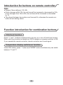
Function introduction for combination buttons
Child lock function
Press “+” and “-” buttons simultaneously can turn on or turn off child lock function.
When child lock function is started up, LOCK indicator on remote controller is ON.
If you operate the remote controller, remote controller won’t send signal.
Temperature display switchover function
8QGHU2))VWDWXVSUHVV³´EXWWRQDQG³02'(´ EXWWRQVLPXOWDQHRXVO\FDQVZLWFK
between °C and °F.
6
Operation guide
1.$IWHUSXWWLQJWKURXJKWKHSRZHUSUHVV212))EXWWRQRQUHPRWHFRQWUROOHUWR
turn on the air conditioner.
2.3UHVV02'(EXWWRQWRVHOHFW\RXUUHTXLUHGPRGH$872&22/'5<)$1
+($7
3. Press "+" or "-" button to set your required temperature. (Temperature can’t be
adjusted under auto mode).
4.3UHVV)$1EXWWRQWRVHW\RXUUHTXLUHGIDQVSHHGDXWRORZPHGLXPDQGKLJK
speed.
5. Press "SWING" button to select fan blowing angle.
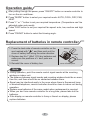
Replacement of batteries in remote controller
1. Press the back side of remote controller on the
spot marked with " ", and then push out the
cover of battery box along the arrow direction.
5HSODFHWZR1R$$$9GU\EDWWHULHVDQG
make sure the positions of + and- polar are
correct.
3. Reinstall the cover of battery box.
battery
reinstall
remove
cover of battery box
Note:
Ɣ'XULQJRSHUDWLRQSRLQWWKHUHPRWHFRQWUROVLJQDOVHQGHUDWWKHUHFHLYLQJ
window on indoor unit.
ƔThe distance between signal sender and receiving window should be no more
than 8m, and there should be no obstacles between them.
Ɣ6LJQDOPD\EHLQWHUIHUHGHDVLO\LQWKHURRPZKHUHWKHUHLVÀXRUHVFHQWODPS
or wireless telephone; remote controller should be close to indoor unit during
operation.
Ɣ5HSODFHQHZEDWWHULHVRIWKHVDPHPRGHOZKHQUHSODFHPHQWLVUHTXLUHG
Ɣ:KHQ\RXGRQ¶WXVHUHPRWHFRQWUROOHUIRUDORQJWLPHSOHDVHWDNHRXWWKH
batteries.
Ɣ,IWKHGLVSOD\RQUHPRWHFRQWUROOHULVIX]]\RUWKHUH¶VQRGLVSOD\SOHDVH
replace batteries.
7
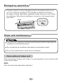
Emergency operation
If remote controller is lost or damaged, please use auxiliary button to turn
on or turn off the air conditioner. The operation in details are as below:
$VVKRZQLQWKH¿J2SHQSDQHOSUHVVDX[EXWWRQWRWXUQRQRUWXUQRIIWKH
air conditioner. When the air conditioner is turned on, it will operate under
auto mode.
panel
aux. button
Clean and maintenance
Note:
Ŷ7XUQRIIWKHDLUFRQGLWLRQHUDQGGLVFRQQHFWWKHSRZHUEHIRUHFOHDQLQJWKHDLU
conditioner to avoid electric shock.
Ŷ'RQRWZDVKWKHDLUFRQGLWLRQHUZLWKZDWHUWRDYRLGHOHFWULFVKRFN
Ŷ'RQRWXVHYRODWLOHOLTXLGWRFOHDQWKHDLUFRQGLWLRQHU
Clean surface of indoor unit
When the surface of indoor unit is dirty, it is recommended to use a soft dry cloth
or wet cloth to wipe it.
Note:
Ɣ'RQRWUHPRYHWKHSDQHOZKHQFOHDQLQJLW
8
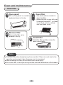
Clean and maintenance
&OHDQ¿OWHU
1
Open panel
2
5HPRYH¿OWHU
&OHDQ¿OWHU
3
Pull out the panel to a certain
DQJOHDVVKRZQLQWKH¿J
5HPRYHWKH¿OWHUDVLQ
GLFDWHGLQWKH¿J
4
Ɣ8VHGXVWFDWFKHURUZDWHUWR
FOHDQWKH¿OWHU
Ɣ:KHQWKH¿OWHULVYHU\GLUW\XVH
the water (below 45ć ) to clean
it, and then put it in a shady
and cool place to dry.
,QVWDOO¿OWHU
,QVWDOOWKH¿OWHUDQGWKHQFORVHWKH
panel cover tightly.
Note:
Ŷ7KH¿OWHUVKRXOGEHFOHDQHGHYHU\WKUHHPRQWKV,IWKHUHLVPXFKGXVWLQWKH
operation environment, clean frequency can be increased.
Ŷ$IWHUUHPRYLQJWKH¿OWHUGRQRWWRXFK¿QVWRDYRLGLQMXU\
Ŷ'RQRWXVH¿UHRUKDLUGU\HUWRGU\WKH¿OWHUWRDYRLGGHIRUPDWLRQRU¿UHKD]DUG
9
Clean and maintenance
Checking before use-season
1. Check whether air inlets and air outlets are blocked.
2. Check whether circuit break, plug and socket are in good condition.
&KHFNZKHWKHU¿OWHULVFOHDQ
4. Check whether mounting bracket for outdoor unit is damaged or corroded.
If yes, please contact dealer.
5. Check whether drainage pipe is damaged.
Checking after use-season
1. Disconnect power supply.
&OHDQ¿OWHUDQGLQGRRUXQLW¶VSDQHO
3. Check whether mounting bracket for outdoor unit is damaged or corroded.
If yes, please contact dealer.
Notice for recovery
1. Many packing materials are recyclable materials.
Please dispose them in appropriate recycling unit.
2. If you want to dispose the air conditioner, please contact local dealer or
consultant service center for the correct disposal method.
10
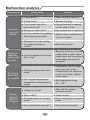
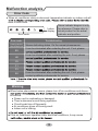
Malfunction analysis
General phenomenon analysis
Please check below items before asking for maintenance. If the malfunction still
FDQ¶WEHHOLPLQDWHGSOHDVHFRQWDFWORFDOGHDOHURUTXDOL¿HGSURIHVVLRQDOV
Phenomenon
Check items
Solution
Ɣ:KHWKHULW
VLQWHUIHUHGVHYHUHO\ Ɣ3XOORXWWKHSOXJ5HLQVHUW
(such as static electricity, stable the plug after about 3min, and
voltage)?
then turn on the unit again.
Indoor unit
can’t receive
remote
controller’s
signal or
remote
controller
has no
action.
Ɣ:KHWKHUUHPRWHFRQWUROOHULV
within the signal receiving
range?
Ɣ6LJQDOUHFHLYLQJUDQJHLVP
Ɣ:KHWKHUWKHUHDUHREVWDFOHV"
Ɣ5HPRYHREVWDFOHV
Ɣ:KHWKHUUHPRWHFRQWUROOHULV
ƔSelect proper angle and point
the remote controller at the repointing at the receiving
ceiving window on indoor unit.
window?
Ɣ,VVHQVLWLYLW\RIUHPRWHFRQWUR Ɣ&KHFNWKHEDWWHULHV,IWKH
power of batteries is too low,
OOHUORZIX]]\GLVSOD\DQGQR
please replace them.
display?
Ɣ&KHFNZKHWKHUUHPRWHFRQW
Ɣ1RGLVSOD\ZKHQRSHUDWLQJ
roller appears to be damaged.
remote controller?
If yes, replace it.
Ɣ)OXRUHVFHQWODPSLQURRP"
No air
emitted
from
indoor
unit
Ɣ7DNHWKHUHPRWHFRQWUROOHU
close to indoor unit.
Ɣ7XUQRIIWKHÀXRUHVHQWODPS
and then try it again.
Ɣ$LULQOHWRUDLURXWOHWRILQGRRU
unit is blocked?
Ɣ(OLPLQDWHREVWDFOHV
Ɣ8QGHUKHDWLQJPRGHLQGRRU
temperature is reached to set
temperature?
Ɣ$IWHUUHDFKLQJWRVHWWHPSHU
ature, indoor unit will stop blowing out air.
Ɣ+HDWLQJPRGHLVWXUQHGRQMXVW Ɣ,QRUGHUWRSUHYHQWEORZLQJ
now?
out cold air, indoor unit will be
started after delaying for several minutes, which is a normal phenomenon.
11
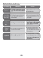
Malfunction analysis
Phenomenon
$LUFRQGLW
ioner can’t
operate
Mist is emitted from
indoor unit’s
air outlet
Set temperature can’t
be adjusted
Cooling
(heating)
effect is
not good.
Check items
Solution
Ɣ3RZHUIDLOXUH"
Ɣ:DLWXQWLOSRZHUUHFRYHU\
Ɣ,VSOXJORRVH"
Ɣ5HLQVHUWWKHSOXJ
Ɣ&LUFXLWEUHDNWULSVRIIRU
fuse is burnt out?
Ɣ$VNSURIHVVLRQDOWRUHSODFH
circuit break or fuse.
Ɣ:LULQJKDVPDOIXQFWLRQ"
Ɣ$VNSURIHVVLRQDOWRUHSODFHLW
Ɣ8QLWKDVUHVWDUWHGLPPHGLDWHO\
Ɣ:DLWIRUPLQDQGWKHQWXUQ
after stopping operation?
on the unit again.
Ɣ:KHWKHUWKHIXQFWLRQVHWWLQJ
for remote controller is
correct?
Ɣ5HVHWWKHIXQFWLRQ
Ɣ,QGRRUWHPSHUDWXUHDQGKXP
idity is high?
Ɣ%HFDXVHLQGRRUDLULVFRROHG
UDSLGO\$IWHUDZKLOHLQGRRU
temperature and humidity will
be decrease and mist will
disappear.
Ɣ8QLWLVRSHUDWLQJXQGHUDXWR
mode?
Ɣ7HPSHUDWXUHFDQ¶WEHDGMX
sted under auto mode.
Please switch the operation
mode if you need to adjust
temperature.
Ɣ<RXUUHTXLUHGWHPSHUDWXUH
exceeds the set temperature
range?
Ɣ6HWWHPSHUDWXUHUDQJH
16ć ~30ć .
Ɣ9ROWDJHLVWRRORZ"
Ɣ:DLWXQWLOWKHYROWDJH
resumes normal.
Ɣ)LOWHULVGLUW\"
Ɣ&OHDQWKH¿OWHU
Ɣ6HWWHPSHUDWXUHLVLQSURSHU
range?
Ɣ$GMXVWWHPSHUDWXUHWRSURSHU
range.
Ɣ'RRUDQGZLQGRZDUHRSHQ"
Ɣ&ORVHGRRUDQGZLQGRZ
12
Malfunction analysis
Phenomenon
Check items
Solution
Odours are
emitted
Ɣ:KHWKHUWKHUH¶VRGRXUVRXUFH Ɣ(OLPLQDWHWKHRGRXUVRXUFH
such as furniture and cigarette,
Ɣ&OHDQWKH¿OWHU
etc.
$LUFRQGLWLR
ner operates
abnormally
Ɣ:KHWKHUWKHUH¶VLQWHUIHUHQFH
such as thunder, wireless
devices, etc.
Ɣ'LVFRQQHFWSRZHUSXWEDFN
power, and then turn on the
unit again.
Ɣ+HDWLQJPRGHLVWXUQHGRQ"
Ɣ'XULQJGHIURVWLQJXQGHUKH
ating mode, it may generate
vapor, which is a normal
phenomenon.
Ɣ$LUFRQGLWLRQHULVWXUQHGRQRU
turned off just now?
Ɣ7KHQRLVHLVWKHVRXQGRI
UHIULJHUDQWÀRZLQJLQVLGH
the unit, which is a normal
phenomenon.
Outdoor
unit has
vapor
“Water
ÀRZLQJ´
noise
Cracking
noise
Ɣ$LUFRQGLWLRQHULVWXUQHGRQRU
turned off just now?
13
Ɣ7KLVLVWKHVRXQGRIIULFWLRQ
caused by expansion and/or
contraction of panel or other
parts due to the change of
temperature.
Malfunction analysis
Error Code
Ɣ When air conditioner status is abnormal, temperature indicator on indoor unit will
ation of error code.
Indoor
display
Error code
Error code
Heating indicator
ON 10s OFF 0.5s
E5
H6
Above indicator diagram is only
for reference. Please refer to
actual product for the actual
indicator and position.
Troubleshooting
Means defrosting status. It’s the normal phenomenon.
It can be eliminated after restarting the unit. If not, please
It can be eliminated after restarting the unit. If not, please
&
F1
F2
E6
It can be eliminated after restarting the unit. If not, please
contact qualified professionals for service.
service.
Warning
Ŷ:KHQEHORZSKHQRPHQRQRFFXUVSOHDVHWXUQRff air conditioner and disconfor service.
Ɣ3RZHUFRUGLVRYHUKHDWLQJRUGDPDJHG
Ɣ There’s abnormal sound during operation.
Ɣ&LUFXLWEUHDNWULSVRff frequently.
Ɣ Air conditioner gives off burning smell.
Ɣ,QGRRUXQLWLVOHDNLQJ
Ŷ,IWKHDLUFRQGLWLRQHURSHUDWHVXQGHUDEQRUPDOFRQGLWLRQVLWPD\FDXVH
14
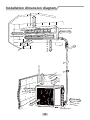
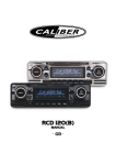
$WOHDVWFP
Space to the ceiling
Installation dimension diagram
Space to the wall
$WOHDVWFP
$WOHDVWFP
P
V
OHD
$W
ce
he
ot
6SDFHWRWKHÀRRU
F
W
n
tio
uc
str
ob
t
he
ot n
t
e
ac uctio
p
S str
W
ob
DV
H
O
$W cm
30
$WOHDVWFP
Space to the obstruction
a
Sp
$WOHDVWFP
Space to the wall
$WOHDVWF
P
Space to th
e wall
n
tio
c
tru
s
Sp
ac
o
et
the
ob
$WOHDVWFP
P
F
W
V
OHD
Space to the
obstruction
$W
Drainage pipe
15
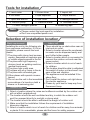
Tools for installation
1 Level meter
2 Screw driver
3 Impact drill
4 Drill head
5 Pipe expander
6 Torque wrench
7 Open-end wrench
8 Pipe cutter
9 Leakage detector
10 Vacuum pump
11 Pressure meter
8QLYHUVDOPHWHU
13 Inner hexagon spanner
Note:
14 Measuring tape
Ɣ3OHDVHFRQWDFWWKHORFDODJHQWIRULQVWDOODWLRQ
Ɣ'RQ
WXVHXQTXDOL¿HGSRZHUFRUG
Selection of installation location
Basic requirement
Installing the unit in the following places maycause malfunction. If it is unavoidable, please consult the local
dealer:
1.The place with strong heat sources,
YDSRUVÀDPPDEOHRUH[SORVLYHJDV,
or volatile objects spread in the air.
2.The place with high-frequency
devices (such as welding machine,
medical equipment).
3.The place near coast area.
4.The place with oil or fumes in the air.
5.The place with sulfureted gas.
6.Other places with special circumstances.
7.Do not use the unit in the immediate
surroundings of a laundry a bath a
shower or a swimming pool.
Outdoor unit
Indoor unit
1. There should be no obstruction near air
inlet and air outlet.
2. Select a location where the condensation water can be dispersed easily and
won't affect other people.
3. Select a location which is convenient to
connect the outdoor unit and near the
power socket.
4. Select a location which is out of reach
for children.
5. The location should be able to withstand
the weight of indoor unit and won't increase noise and vibration.
6. The appliance must be installed 2.5m
DERYHÀRRU
7. Don't install the indoor unit right above
the electric appliance.
8. Please try your best to keep way from
ÀXRUHVFHQWODPS
6HOHFWDORFDWLRQZKHUHWKHQRLVHDQGRXWÀRZDLUHPLWWHGE\WKHRXWGRRUXQLW
will not affect neighborhood.
2. The location should be well ventilated and dry, in which the outdoor unit
won't be exposed directly to sunlight or strong wind.
3. The location should be able to withstand the weight of outdoor unit.
4. Make sure that the installation follows the requirement of installation
dimension diagram.
5. Select a location which is out of reach for children and far away from animals
or plants.If it is unavoidable, please add the fence for safety purpose.
16
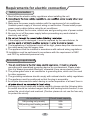
Requirements for electric connection
Safety precaution
1. Must follow the electric safety regulations when installing the unit.
circuit break.
3. Make sure the power supply matches with the requirement of air conditioner.
Unstable power supply or incorrect wiring or malfunction. Please install proper
power supply cables before using the air conditioner.
4. Properly connect the live wire, neutral wire and grounding wire of power socket.
5. Be sure to cut off the power supply before proceeding any work related to
electricity and safety.
7. If the supply cord is damaged, it must be replaced by the manufacturer, its
8. The temperature of refrigerant circuit will be high, please keep the interconnection cable away from the copper tube.
9. The appliance shall be installed in accordance with national wiring regulations.
10.Installation must be performed in accordance with the requirement of NEC
and CEC by authorized personnel only
Grounding requirement
grounding with specialized grounding device by a professional. Please make
sure it is always grounded effectively, otherwise it may cause electric shock.
2. The yellow-green wire in air conditioner is grounding wire, which can't be used
for other purposes.
3. The grounding resistance should comply with national electric safety regulations.
4. The appliance must be positioned so that the plug is accessible.
5. An all-pole disconnection switch having a contact separation of at least 3mm in
6. Including an circuit break with suitable capacity, please note the following table.
Air switch should be included magnet buckle and heating buckle function, it can
protect the circuit-short and overload. (Caution: please do not use the fuse only
for protect the circuit)
Air-conditioner
18K(cooling only model)
Circuit break capacity
20A
18K(cooling and heating model)
24K
25A
25A
17
Installation of indoor unit
Step one: choosing installation location
rm it with the client.
Step two: install wall-mounting frame
1. Hang the wall-mounting frame on the wall; adjust it in horizontal position with the
plastic expansion particles in the holes.
3. Fix the wall-mounting frame on the wall with tapping screws (ST4.2X25TA) and
.
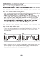
Step three: open piping hole
1. Choose the position of piping hole according to the direction of outlet pipe. The
position of piping hole should be a little lower than the wall-mounted frame,
shown as below.
18K:
Wall
24K:
Mark in the middle of it
Space
to the
wall
above
PP
Left
ĭPP
Rear piping hole
Level meter
Wall
Wall
Space
to the
wall
above
PP
Mark in the middle of it
Space
to the
wall
above
PP
Right
ĭPP
Rear piping hole
Left
ĭPP
Rear piping hole
Level meter
Wall
Space
to the
wall
above
PP
Right
ĭPP
Rear piping hole
2SHQDSLSLQJKROHZLWKWKHGLDPHWHURIĭoUĭRQWKHVHOHFWHGRXWOHWSLSH
position. In order to drain smoothly, slant the piping hole on the wall slightly
GRZQZDUGWRWKHRXWGRRUVLGHZLWKWKHJUDGLHQWRI
18
Installation of indoor unit
Indoor
Note:
Ɣ3D\DWWHQWLRQWRGXVWSUHYHQWLRQDQG
WDNHUHOHYDQWVDIHW\PHDVXUHVZKHQ
opening the hole.
Ɣ The plastic expansion particles are
QRWSURYLGHGDQGVKRXOGEHERXJKW
locally.
outdoor
ĭ
ĭ
5-10
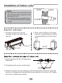
Step four: outlet pipe
2. When select leading out the pipe
from left or right, please cut off the
corresponding hole on the bottom
case.
1. The pipe can be led out in the
direction of right, rear right, left or
rear left.
left
right
left
rear right
rear left
right
cut off
the hole
1. Aim the pipe joint at the corresponding
bellmouth.
pipe joint
union nut
pipe
2. Pretightening the union nut with hand.
3. Adjust the torque force by referring to the following sheet. Place the open-end
wrench on the pipe joint and place the torque wrench on the union nut. Tighten
the union nut with torque wrench.
19
Installation of indoor unit
open-end
wrench
union nut
torque wrench
pipe
Hex nut diameter Tightening torque (N.m)
ĭ
15~20
ĭ
30~40
ĭ
40~55
ĭ
60~65
ĭ
70~75
indoor pipe
4. Wrap the indoor pipe and joint of connection pipe with insulating pipe, and
then wrap it with tape.
insulating pipe
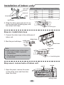
Step six: install drain hose
1. Connect the drain hose to the outlet pipe of
indoor unit.
drain hose
outlet pipe
2. Bind the joint with tape.
outlet
pipe
tape
drain hose
drain hose
Note:
Ɣ$GGLQVXODWLQJSLSHLQWKHLQGRRU
drain hose in order to prevent
condensation.
Ɣ7KHSODVWLFH[SDQVLRQSDUWLFOHVDUH
not provided.
insulating pipe
Step seven: connect wire of indoor unit
panel
screw
1. Open the panel, remove the screw
on the wiring cover and then take
down the cover.
wiring cover
20
Installation of indoor unit
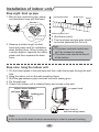
2. Make the power connection wire go
through the cable-cross hole at the back
RILQGRRUXQLWDQGWKHQSXOOLWRXWIURP
the front side.
cable-cross
hole
power connection
wire
5HPRYHWKHZLUHFOLSFRQQHFWWKHSRZHUFRQQHFWLRQZLUHWRWKHZLULQJWHUPLQDO
with wire clip.
N(1)
2
N(1)
2
L1
L2
G
Outdoor unit connection
4. Put wiring cover back and then tighten the screw.
5. Close the panel.
Note:
Ɣ All wires of indoor unit and outdoor unit should be connected by a professional.
for a new one. Avoid extending the wire by yourself.
installation.
Ɣ)RUWKHDLUFRQGLWLRQHUZLWKRXWSOXJDQFLUFXLWEUHDNPXVWEHLQVWDOOHGLQWKHOLQH
The circuit break should be all-pole parting and the contact parting distance
VKRXOGEHPRUHWKDQPP
21
Installation of indoor unit
Step eight: bind up pipe
1. Bind up the connection pipe, power
cord and drain hose with the band.
connection pipe
drain hose
band
indoor and
outdoor power cord
indoor unit
gas
pipe
indoor power cord
liquid pipe
3. Bind them evenly.
4. The liquid pipe and gas pipe should
be bound separately at the end.
band
drain hose
2. Reserve a certain length of drain
hose and power cord for installation
when binding them. When binding to
a certain degree, separate the indoor
power and then separate the drain
hose.
Note:
Ɣ7KHSRZHUFRUGDQGFRQWUROZLUH
can't be crossed or winding.
Ɣ7KHGUDLQKRVHVKRXOGEHERXQG
at the bottom.
Step nine: hang the indoor unit
1. Put the bound pipes in the wall pipe and then make them pass through the wall
hole.
2. Hang the indoor unit on the wall-mounting frame.
3. Stuff the gap between pipes and wall hole with sealing gum.
4. Fix the wall pipe.
&KHFNLIWKHLQGRRUXQLWLVLQVWDOOHG¿UPO\DQGFORVHGWRWKHZDOO
indoor
wall pipe
upper hook
outdoor
sealing gum
lower hook of
wall-mounting frame
Note:
Ɣ'RQRWEHQGWKHGUDLQKRVHWRRH[FHVVLYHO\LQRUGHUWRSUHYHQWEORFNLQJ
22
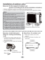
Installation of outdoor unit
6WHSRQH¿[WKHVXSSRUWRIRXWGRRUXQLW
(select it according to the actual installation situation)
1. Select installation location according to the house structure.
2. Fix the support of outdoor unit on the selected location with expansion screws.
Note:
Ɣ7DNHVXI¿FLHQWSURWHFWLYHPHDVXUHVZKHQ
installing the outdoor unit.
ƔMake sure the support can withstand at least
four times of the unit weight.
Ɣ7KHRXWGRRUXQLWVKRXOGEHLQVWDOOHGDWOHDVW
FPDERYHWKHÀRRULQRUGHUWRLQVWDOOGUDLQ
joint.
Ɣ)RUWKHXQLWZLWKFRROLQJFDSDFLW\RI:
~5000W, 6 expansion screws are needed;
for the unit with cooling capacity of 6000W
~8000W, 8 expansion screws are needed;
for the unit with cooling capacity of 10000W at least 3cm above the floor
~16000W, 10 expansion screws are needed.
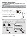
6WHSWKUHH¿[RXWGRRUXQLW
Step two: install drain joint
(Only for cooling and heating
unit)
1. Place the outdoor unit on the
support.
2. Fix the foot holes of outdoor unit
with bolts.
1. Connect the outdoor drain joint into
the hole on the chassis, as shown in
the picture below.
2. Connect the drain hose into the drain
vent.
drain vent
Drain hose
foot holes
foot holes
chassis
outdoor drain joint
23
Installation of outdoor unit
Step four: connect indoor and outdoor pipes
1. Remove the screw on the right handle of outdoor unit and then remove
the handle.
3. Pretightening the union nut with
hand.
pipe joint
screw
union nut
handle
2. Remove the screw cap of valve and
aim the pipe joint at the bellmouth of
pipe.
4. Tighten the union nut with torque
wrench by referring to the sheet
below.
torque
Hex nut diameter Tightening
(N.m)
ĭ
a
ĭ
30~40
ĭ
a
ĭ
a
ĭ
a
liquid pipe
liquid
valve
gas pipe
gas valve
1. Remove the wire clip; connect the power connection wire and signal control
wire (only for Cool and heat type) to the wiring terminal according to the color;
N(1)
2
3
L1
L2
G
L2
L1
POWER
N(1)
2
3
Indoor unit connection
24
Installation of outdoor unit
2. Fix the power connection wire and signal control wire with wire clip (only for
cooling and heating unit).
Note:
Ɣ$IWHUWLJKWHQWKHVFUHZSXOOWKHSRZHUFRUGVOLJKWO\WRFKHFNLILWLV¿UP
Ɣ1HYHUFXWWKHSRZHUFRQQHFWLRQZLUHWRSURORQJRUVKRUWHQWKHGLVWDQFH
Step six: neaten the pipes
1. The pipes should be placed along the wall,
bent reasonably and hidden possibly. Min.
semidiameter of bending the pipe is 10cm.
2. If the outdoor unit is higher than the wall
KROH\RXPXVWVHWD8VKDSHGFXUYHLQWKH
pipe before pipe goes into the room, in
order to prevent rain from getting into the
room.
wall
U-shaped curve
drain hose
Note:
Ɣ7KHWKURXJKZDOKHLJKWRIGUDLQKRVH
shouldn't be higher than the outlet
pipe hole of indoor unit.
Ɣ6ODQWWKHGUDLQKRVHVOLJKWO\GRZ
nwards. The drain hose can't be
FXUYHGUDLVHGDQGÀXFWXDQWHWF
the drain hose
can't raise
upwards.
The drain hose can't be fluctuant
Ɣ7KHZDWHURXWOHWFDQ
WEHSODFHG
in water in order to drain smoothly.
The drain hose
can't be fluctuant
The water outlet
can't be placed
in water
25
The water
outlet can't be
fluctuant
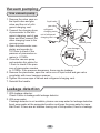
Vacuum pumping
Use vacuum pump
1. Remove the valve caps on
liquid valve
the liquid valve and gas
piezometer
Lo
Hi
valve and the nut of refrigas valve
gerant charging vent.
refrigerant
valve cap
2. Connect the charging hose
charging vent
RISLH]RPHWHUWRWKHUHIUL
gerant charging vent of gas nut of refrigerant
valve and then connect the charging vent
other charging hose to the
vacuum pump
vacuum pump.
2SHQWKHSLH]RPHWHUFRP
inner hexagon
pletely and operate for
spanner
10-15min to check if the
SUHVVXUHRISLH]RPHWHUUH
close
mains in -0.1MPa.
4. Close the vacuum pump
open
and maintain this status for
1-2min to check if the presVXUHRISLH]RPHWHUUHPDLQV
in -0.1MPa. If the pressure decreases, there may be leakage.
5HPRYHWKHSLH]RPHWHURSHQWKHYDOYHFRUHRIOLTXLGYDOYHDQGJDVYDOYH
completely with inner hexagon spanner.
6. Tighten the screw caps of valves and refrigerant charging vent.
7. Reinstall the handle.
Leakage detection
1. With leakage detector:
Check if there is leakage with leakage detector.
2. With soap water:
If leakage detector is not available, please use soap water for leakage detection.
$SSO\VRDSZDWHUDWWKHVXVSHFWHGSRVLWLRQDQGNHHSWKHVRDSZDWHUIRUPRUH
than 3min. If there are air bubbles coming out of this position, there's a leakage.
26
Check after installation
Ɣ&KHFNDFFRUGLQJWRWKHIROORZLQJUHTXLUHPHQWDIWHU¿QLVKLQJLQVWDOODWLRQ
Items to be checked
Possible malfunction
+DVWKHXQLWEHHQLQVWDOOHG¿UPO\"
The unit may drop, shake or emit noise.
Have you done the refrigerant leakage
test?
,WPD\FDXVHLQVXI¿FLHQWFRROLQJ
(heating) capacity.
,VKHDWLQVXODWLRQRISLSHOLQHVXI¿FLHQW"
It may cause condensation and water
dripping.
Is water drained well?
It may cause condensation and water
dripping.
Is the voltage of power supply according to the voltage marked on the
nameplate?
It may cause malfunction or damaging
the parts.
Is electric wiring and pipeline installed
correctly?
It may cause malfunction or damaging
the parts.
Is the unit grounded securely?
It may cause electric leakage.
Does the power cord follow the speci¿FDWLRQ"
It may cause malfunction or damaging
the parts.
Is there any obstruction in the air inlet
and outlet?
,WPD\FDXVHLQVXI¿FLHQWFRROLQJ
(heating) capacity.
The dust and sundries caused during
installation are removed?
It may cause malfunction or damaging
the parts.
The gas valve and liquid valve of
connection pipe are open completely?
,WPD\FDXVHLQVXI¿FLHQWFRROLQJ
(heating) capacity.
Test operation
1. Preparation of test operation
Ɣ7KHFOLHQWDSSURYHVWKHDLUFRQGLWLRQHU
Ɣ6SHFLI\WKHLPSRUWDQWQRWHVIRUDLUFRQGLWLRQHUWRWKHFOLHQW
2. Method of test operation
Ɣ3XWWKURXJKWKHSRZHUSUHVV212))EXWWRQRQWKHUHPRWHFRQWUROOHUWRVWDUW
operation.
Ɣ3UHVV02'(EXWWRQWRVHOHFW$872&22/'5<)$1DQG+($7WRFKHFN
whether the operation is normal or not.
Ɣ,IWKHDPELHQWWHPSHUDWXUHLVORZHUWKDQć , the air conditioner can’t
start cooling.
27
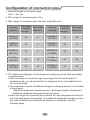
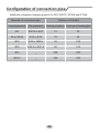
&RQ¿JXUDWLRQRIFRQQHFWLRQSLSH
1. Standard length of connection pipe
ƔPPP
2. Min. length of connection pipe is 3m.
3. Max. length of connection pipe and max. high difference.
Cooling
capacity
Max length
Max height
of connecdifference
tion pipe
Cooling
capacity
Max length
Max height
of connecdifference
tion pipe
5000Btu/h
(1465W)
15
5
24000Btu/h
(7032W)
25
10
7000Btu/h
(2051W)
15
5
28000Btu/h
(8204W)
30
10
9000Btu/h
(2637W)
15
5
36000Btu/h
(10548W)
30
20
12000Btu/h
(3516W)
20
10
42000Btu/h
(12306W)
30
20
18000Btu/h
(5274W)
25
10
48000Btu/h
(14064W)
30
20
4. The additional refrigerant oil and refrigerant charging required after prolonging
connection pipe
Ɣ$IWHUWKHOHQJWKRIFRQQHFWLRQSLSHLVSURORQJHGIRUPDWWKHEDVLVRI
standard length, you should add 5ml of refrigerant oil for each additional 5m
of connection pipe.
Ɣ7KHFDOFXODWLRQPHWKRGRIDGGLWLRQDOUHIULJHUDQWFKDUJLQJDPRXQWRQWKHEDVLV
of liquid pipe):
$GGLWLRQDOUHIULJHUDQWFKDUJLQJDPRXQW SURORQJHGOHQJWKRIOLTXLGSLSHî
additional refrigerant charging amount per meter
Ɣ:KHQWKHOHQJWKRIFRQQHFWLRQSLSHLVDERYHPDGGUHIULJHUDQWDFFRUGLQJWR
the prolonged length of liquid pipe. The additional refrigerant charging amount
per meter is different according to the diameter of liquid pipe. See the
following sheet.
28
&RQ¿JXUDWLRQRIFRQQHFWLRQSLSH
$GGLWLRQDOUHIULJHUDQWFKDUJLQJDPRXQWIRU55&5$DQG5D
Diameter of connection pipe
Outdoor unit throttle
Cooling only(g/m) Cooling and heating(g/m)
Liquid pipe(mm)
Gas pipe(mm)
ĭ
ĭRUĭ
15
20
ĭRUĭ
ĭRUĭ
15
50
ĭ
ĭRUĭ
30
120
ĭ
ĭRUĭ
60
120
ĭ
_
250
250
ĭ
_
350
350
29
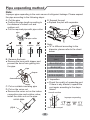
Pipe expanding method
Note:
Improper pipe expanding is the main cause of refrigerant leakage. Please expand
the pipe according to the following steps:
$&XWWKHSLSH
Ɣ&RQ¿UPWKHSLSHOHQJWKDFFRUGLQJWR
the distance of indoor unit and
outdoor unit.
Ɣ&XWWKHUHTXLUHGSLSHZLWKSLSHFXWWHU
E: Expand the port
Ɣ([SDQGWKHSRUWZLWKH[SDQGHU
hard
mold
expander
pipe
pipe
pipe cutter
leaning
uneven
Note:
Ɣ$LVGLIIHUHQWDFFRUGLQJWRWKH
diameter, please refer to the sheet
below:
burr
B: Remove the burrs
Ɣ5HPRYHWKHEXUUVZLWKVKDSHUDQG
prevent the burrs from getting into
the pipe.
pipe
shaper
downwards
$PP
Outer diameter
(mm)
Max
Min
ĭ
1.3
0.7
ĭ
1.6
1.0
ĭ
1.8
1.0
ĭ
2.4
2.2
F: Inspection
Ɣ&KHFNWKHTXDOLW\RIH[SDQGLQJSRUW
If there is any blemish, expand the
port again according to the steps
above.
C: Put on suitable insulating pipe
D: Put on the union nut
Ɣ5HPRYHWKHXQLRQQXWRQWKHLQGRRU
connection pipe and outdoor valve;
install the union nut on the pipe.
smooth surface
improper expanding
union pipe
leaning
pipe
the length is equal
30
damaged
surface
crack
uneven
thickness
5610NW 12Ave
Sui
t
e20921
1
For
tLauder
dal
e,FL33309
Ph:9547711415
Fx:9547711418
ht
t
p:
/
/
www.
ai
r
coni
nt
.
com