1
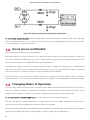
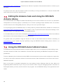
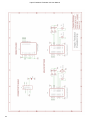
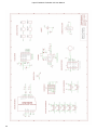
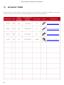
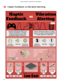
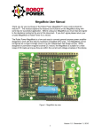
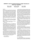
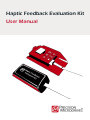
Haptic Feedback Evaluation Kit
User Manual
Contents
1 Introduction ….……...….….….....….…...…..….….….…........….….……..………………..…...….……………………..…...….……..………….
1
2 System Overview .….…...…..….….….…........….….……..………………..…...….…………..……..…………………..…...….…………………
2
2.1 The Haptic Controller .….…...…..….….….…........….….……..………………..…...….……..………………..…...….………………..
3
2.2 The Haptic Grip .….…...…..….….….…........….….……..………………..…...….………….……..….…………..…...….………………..
5
2.3 Firmware (Arduino Code) .….…...…..….….….…........….….……..………………..…...…………………..…...….………………..
6
3 Setup and Installation .….…...…..….….….…........….….……..………………..…...….………………….…………..…...….…………………
7
3.1 Powering via USB .….…...…..….….….…........….….……..………………..…...….………..……….…………..…...….………………..
7
3.2 Warning on DC Power Connector .….…...…..….….….…........….….……..……………….…………..…...….………………..
7
3.3 Installing the Arduino Drivers and Software .….…...…..….….….…........….….…………………..…...….………………..
8
4 Intro Mode Operation .….…...…..….….….…........….….……..………………..…...……….…………..…...….……………….……………..
9
4.1 Navigation .….…...…..….….….…........….….……..………………..…...….…………………………….…………..…...….………………..
9
4.2 Menu Options .….…...…..….….….…........….….……..………………..…...….……………..………..…………..…...….……………....
9
4.2.1 Quick-Start Demo .….…...…..….….….…........….….……..………………..…...….……...…………..…...….………………
9
4.2.2 Haptic Feedback Tutorial .….…...…..….….….…........….….……..…………………….…………..…...….……………… 10
4.2.3 Vibration Alerting Tutorial .….…...…..….….….…........….….……..………………..……………..…...….………….….
10
4.2.4 DRV2605 Overview .….…...…..….….….…........….….……..………………..…...….…..…………..…...….……………..
10
5 Engineering Mode Operation .….…...…..….….….…........….….……..………………..…...….………………..…...….…………………. 11
5.1 Navigation .….…...…..….….….…........….….……..………………..…...….…………………………….…………..…...….……………….. 11
5.2 True Haptics .….…...…..….….….…........….….……..………………..…...….………………………….…………..…...….………….……. 11
5.3 Vibration Alerting .….…...…..….….….…........….….……..………………..…...….……………………………..…...….……………..… 12
5.4 Debugging Feature .….…...…..….….….…........….….……..………………..…...….……………..…………..…...….………….……. 14
6 Development Mode Operation ……..…………………….………….…….….……….…….……….….….………………….….…………….. 16
6 Advanced Options .….…...…..….….….…........….….……..………………..…...….…………………………………..…...….……………….… 17
6.1 Test Points .….…...…..….….….…........….….……..………………..…...….……………………………..…………..…...….……………….. 17
6.2 External Signals / Actuators .….…...…..….….….…........….….……..………………..…...………………..…...….……………….. 17
6.3 Direct Access to DRV2605 .….…...…..….….….…........….….……..………………..…...….….…………..…...….…………….….
18
6.4 Changing Modes of Operation .….…...…..….….….…........….….……..………………..…..…………..…...….…………….….
18
6.5 Editing the Arduino Code and Using the DRV2605 Arduino Library …….……….….….….……………….….. 19
6.6 Using The DRV2605 Auto Calibrate Feature .……….………….….………….………….….….….………….……………….
19
7 Appendices .….…...…..….….….…........….….……..………………..…...….…………………………………..…………..…...….………………...
20
Haptic Feedback Evaluation Kit User Manual
Introduction
The Haptic Feedback Evaluation Kit is an open-source platform for experiencing haptic feedback and vibration
alerting.
It serves a wide range of users. Those unfamiliar with the technology will benefit from the introductory mode and its
tutorials. In addition, the kit will support engineers and product designers throughout the development process by
providing an easy to use platform for hardware and software prototyping.
This document provides technical details on each section of the kit, guides for installation and usage, and advice for
accessing advanced features. There is also a Quick Start Guide provided with the kit to get users up and running
immediately. Additional copies of the guides and more resources, such as tutorials and example code, can be
downloaded from precisionmicrodrives.com/haptic-kit/features.
It is also recommended you request a copy of the full datasheet for the DRV2605 from Texas Instruments, the haptics
driver which the kit uses. A shortened datasheet is available for download online, and you can request the full copy
using the link in the “Special Note” section here: www.ti.com/product/drv2605.
For additional advice about vibration motors and haptic feedback in general can be found online in the Tech Blog
and App Notes sections of www.precisionmicrodrives.com.
If you experience any issues or are looking for further advice, please contact Precision Microdrives at
[email protected].
ATTENTION: DO NOT use the DC power connector
Only use the USB connection to power the kit, see Section 3.2 for more details
1
Haptic Feedback Evaluation Kit User Manual
System Overview
The Haptic Feedback Evaluation Kit is comprised of two main units, the Haptic Controller and the Haptic Grip.
Figure 1. Haptic Feedback Evaluation Kit System View
The Haptic Controller includes an Arduino Uno R3 with a custom
designed ‘shield’ from Precision Microdrives. It acts as the user
interface, allowing the user to navigate through the menu systems
on the OLED screen using the capacitive touch buttons. It also
houses the hardware used to drive the motors, including a
DRV2605 from Texas Instruments for haptic feedback (Section 5.2)
and a MOSFET for simple vibration alerting (Section 5.3).
Figure 2. The Haptic Controller
The Haptic Grip contains the actuators that play the various vibration patterns sent by the Haptic Controller. The two are connected
by a ribbon cable that carries the power, drive, and motor selection
signals. With 3 different eccentric rotating mass vibration motors
and 1 linear resonant actuator, the grip houses actuators from our
high performance Precision Haptic™ range.
Figure 3. The Haptic Grip
2
Haptic Feedback Evaluation Kit User Manual
The Haptic Controller
Arduino is an open source development platform for electronics which has many different boards available, the Uno
R3 board is based on an Atmel ATmega328 microcontroller. Although the term ‘Arduino’ refers to the project as a
whole, it is colloquially used to refer to the specific board you are using – a convention we will use in this
documentation.
The Arduino allows you to easily program the microcontroller through your computer using software that you can
download online, see Section 3 for installation instructions. Due to its simplicity and versatility it is extremely popular
with hobbyists and professionals who use it for prototyping and other projects. As a result there is a very active online
community where you can find advice and details about the boards.
The stackable headers of the Arduino provide access to various pins on the board, PCBs can be designed to fit directly
onto these headers and are known as ‘shields’.
Arduino shields are often created for a specific purpose such as WIFI connectivity or SD card readers, our Haptic Shield
works with the provided firmware (code for the microcontroller) to provide a user interface and drive the vibration
actuators. This is achieved by including several components, the main ones are listed below.
● Capacitive Touch Buttons
There are 6 capacitive touch buttons that are used to provide the
input to the Haptic Controller. There are slight differences in their
function depending on the mode of operation (Sections 4 & 5).
From the top left, working clockwise, the buttons are:
button,
button,
button,
button,
button, and
button. The buttons themselves rely on MPR121 touch driver
Figure 4. Capacitive Touch Buttons
which communicates over the I2C communications bus.
● Screen
An OLED screen provides visual cues to the user about the current
status of the controller. The menu system is displayed on screen
and navigated using the capacitive touch buttons. Depending on
the mode of operation the screen may display information about
the effect being played, output actuator, or walk through tutorials.
There are 8 lines of orange LEDs at the top and 24 lines of blue
LEDs below. It is controlled via SPI.
3
Figure 5. OLED Screen
Haptic Feedback Evaluation Kit User Manual
●
This is the haptic driver, produced by Texas Instruments. It contains
over 123 different haptic effects, with royalty free licensing from
Immersion, and can drive both ERMs and LRAs. It has a range of
advanced features including overdrive and active braking for haptic
effects, and auto-resonance tracking for LRAs. It is controlled by the
Arduino via I2C communications bus.
Figure 6. DRV2605 Haptic Driver
●
A simple MOSFET is used to drive vibration alerting patterns on the
vibration motors. It uses a simple PWM signal from the Arduino,
where varying the duty cycle controls the speed and vibration
strength of the ERM. The change in duty cycle is handled by the
firmware in the Arduino and you can build your own patterns in the
Engineering Mode (Section 5).
.
Figure 7. MOSFET
●
Touchscreens are a common application for haptic feedback,
where the tactile feel of pressing buttons is lost. Naturally we have
included an LRA (C10-100) on the Haptic Shield to provide the user
with haptic confirmation of their presses on the capacitive touch
surface. It too is driven by the DRV2605 and will give different
effects for different confirmations (which can be changed in the
software).
Figure 8. C10-100 Linear Resonant
Actuator
●
The Haptic Controller is finished with a metal base that supports
the Arduino and Haptic Shield. Mounting holes are positioned to fit
the Arduino, which use rubber mounts to improve mechanical
isolation between metal base and the Arduino with shield. This
helps reduce noise from the LRA vibrating. There is also a clip
section to help secure the ribbon cable to provide strain relief and
stop the connector from being damaged through mishandling.
4
Figure 9. Metal Base Section
Haptic Feedback Evaluation Kit User Manual
The Haptic Grip
The Haptic Grip is a small ergonomic unit that houses the vibrating actuators. Using a separate unit has several
benefits:
● Allows us to easily include multiple actuators.
● Has a form factor that is representative of many end applications
● Helps separate the haptic effect being played from the capacitive buttons on the Haptic Controller by the
LRA
● Allows a user to easily share their haptic experience with a colleague by using the Haptic Controller and
handing the Haptic Grip to someone else.
The Haptic Grip contains a small PCB and has two leaded ERMs
mounted directly into the base, all of which can be accessed by
peeling back the black rubber section from the red metal section.
There is a single quad channel multiplexer / demultiplexer IC that
handles the actuator selection signals from the Haptic Controller,
reducing the need for excessive cabling. To aid debugging, there
is an LED for each actuator which is lit when that actuator is
Figure 10. Haptic Grip Peeled Back
selected by the Haptic Controller in addition to topside connection pads for each motor.
There are 3 eccentric rotating mass vibration motors and 1 linear resonant actuator:
Download 305-000 Datasheet
Download 306-109 Datasheet
Download 308-102 Datasheet
Download C10-100 Datasheet
Figure 11. Haptic Grip Actuator Table
5
Haptic Feedback Evaluation Kit User Manual
Firmware (Arduino Code)
An important part of the Haptic Feedback Evaluation Kit is the firmware code that is loaded into the Arduino. There
are 2 modes of operation provided with the kit (Sections 4 & 5), it is possible to change between these modes as
many times as you like. This is achieved by following the steps in Section 7.4.
The firmware handles several important tasks that tie the separate sections of the system together:
● Building the menu system for user guidance
● Displaying text and images on the OLED screen
● Receiving input from the user through capacitive touch buttons
● Making logical decisions based on the menu system and user input
● Sending motor selection code to multiplexer
● Interfacing with the DRV2605 or MOSFET to play haptic effects or vibration alerting patterns
As the firmware is open source and accessible through the Arduino software environment, it is possible to use the
Haptic Feedback Evaluation Kit as a development platform for prototyping units. Arduino uses its own programming
language based on Wiring, which is essentially a set of C/C++ functions called from the code. Therefore anyone
familiar with C/C++ languages, or the Processing or Wiring projects, should find Arduino development an easy
transition. Libraries and tutorials are provided at precisionmicrodrives.com/haptic-kit.
6
Haptic Feedback Evaluation Kit User Manual
Setup and Installation
The Haptic Feedback Evaluation Kit is designed to operate ‘out-the-box’ allowing users to immediately experience
haptic feedback. Arduinos are powered using either the USB socket or DC power socket, both located at the bottom
of the Haptic Controller.
, see Section 3.2 below.
Powering via USB
The Arduino uses a USB type B socket. This can be used to provide power to the kit as well as accessing the firmware
on the Arduino (see Section 3.4 for installation) and debug information. The USB port can be plugged into a port on
a computer or to a USB wall charger.
the Arduino drivers must be installed. The
default current allocation to a USB device is 100 mA, with the drivers installed the Arduino is able to negotiate up to
500 mA. Please note that some PCs use the same USB bus to power several USB ports, therefore you should unplug
any other USB devices unless you are sure enough current is being supplied to the kit.
double check the rating of the USB wall
charger is no less than 500 mA.
Warning on DC Power Connector
ATTENTION: DO NOT use the DC power connector!
The Arduino includes a DC power socket which is designed to offer a choice in power supply. However it is not
possible to use the DC power socket with the Haptic Shield. Using the DC power risks immediately damaging the
analogue switch.
7
Haptic Feedback Evaluation Kit User Manual
Installing the Arduino Drivers and Software
The installation process for the Arduino is simple, however it is updated periodically through the Arduino website. We
recommend following the most recent steps by visiting the Arduino ‘Getting Started’ page:
arduino.cc/en/Guide/HomePage
The link above will allow you to:
● Install the Arduino Uno R3 drivers
● Install the Arduino coding IDE (recommended but only required if you intend to switch firmware modes,
Section 6.4)
8
Haptic Feedback Evaluation Kit User Manual
Intro Mode Operation
There
are
three
firmware
modes
available,
all
of
which
are
available
for
download
from
precisionmicrodrives.com/haptic-kit/codes.
The “
“ is the default mode of operation and is loaded onto the kit prior to shipping. It is aimed at
non-technical users who are unfamiliar with haptic feedback and vibration alerting. It consists of 4 different tutorials
(more information in Section 4.2:
for a fast explanation of haptic feedback and vibration alerting
●
●
●
for a look at the Texas Instruments DRV2605 features
●
It is recommended you print / load a copy of the “Haptic Feedback vs Vibration Alerting” crib sheet (see appendix D)
to accompany the tutorials. It is especially useful for sharing exactly what is required for implementing each technology.
You can switch to the
firmware to test all the available features of the kit by loading it onto
the Arduino, instructions in Section 6.4.
Navigation
There is a single top-level menu that includes the four demonstrations / tutorials. To navigate between these menu
options, use the
and
buttons. To enter a menu option, press
.
Although they have different content, the menu options all work in the same way. Press
through the slides. At specific points you will be prompted to press the
To repeat the effects, press
to navigate forward
button to experience different effects.
again.
You can exit the current demo / tutorial at any point and return to the top menu by pressing the
Intro Mode the
button. In the
button is not used.
Menu Options
The Quick-Start Demo is a short overview that allows the user to experience vibration alerting first, followed by haptic
feedback. The demonstration is very basic and is suitable for introducing the idea of adding vibration technology to
a device, useful for sharing the concept with non-technical colleagues.
9
Haptic Feedback Evaluation Kit User Manual
The Haptic Feedback Tutorial is designed to give the user an overview of haptic effects with example vibration
patterns. It also includes an example application of a car parking sensor, showing how different haptic vibration
patterns can be used to convey the same information.
The tutorial serves as a good introduction to haptic feedback and can be used by non-technical persons looking to
develop their knowledge in the area. It is also useful for engineers and product developers to experience different
haptic effects and get a quick overview of the capabilities of the DRV2605 and Precision Haptic™ actuators.
The Vibration Alerting Tutorial gives several examples of vibration alerting waveforms. It highlights how a vibration
alerting waveform can be used to alert the user to events, and often represent warnings.
When used in conjunction with the Haptic Feedback Tutorial the user should be able to understand the difference
in the two technologies and recognise if their design would benefit from advanced haptic feedback or the simpler
vibration alerting. It is therefore useful for both non-technical and technical users.
All haptic effects are played by a special haptic feedback driver chip from Texas Instruments, the DRV2605. This
demonstration covers some of the advanced features of the chip, and lets users directly experience how they improve
the vibration output.
It is shorter than the other tutorials and serves as a precursor to downloading the ‘Engineering Firmware’. For this
reason it is of most use to engineers who intend to continue development with the kit and experiment with the
DRV2605 itself.
10
Haptic Feedback Evaluation Kit User Manual
Engineering Mode Operation
To test all the available functions of the kit, the Engineering Mode can be loaded onto the kit once downloaded, see
Section 7.4 for instructions.
It is aimed at technical users and engineers who are ready to start experimenting with haptic feedback and vibration
alerting. It is also required to use some of the advanced features, such as external actuator connection, and further
development.
It is recommended you print / load a copy of the “True Haptics Menu Map” and the “Effect Library and Finder” sheet
(see appendices E and F, and online) to accompany this mode. It is especially useful for navigating to specific effects.
Navigation
The menu system is based on a hierarchy where you move left and right through the menu options (presented as
tabs) and press
to enter the selected menu option. The
button moves you up a menu level and holding
it down returns you to the top level.
In the top menu you can select between experiencing the ‘True Haptic’ waveforms or building your own ‘Vibration
Altering’ pattern.
In ‘Engineering Mode’ the
button cycles through the output actuators.
True Haptics
Here you can access all of the haptic waveforms and libraries stored on the DRV2605. The effects are grouped into
different categories and can be played on each of the actuators.
The screen shows the current status including the Menu Options, current Effect Library, the selected Effect, and the
output Motor:
Figure 12. True Haptic Menu Layout
The tabs at the top will show menu options until you navigate deep enough to the effects. Effects are displayed
differently, and are identified by the effect number. For example, in the menu level “True Haptics -> Clicks ->
11
Haptic Feedback Evaluation Kit User Manual
Double” there are 3 further menu options; Strong, Medium, and Sharp. Selecting the menu option “Medium” displays
6 different effects, Medium 1 to Medium 6.
Figure 13. Menu Option Tab vs Effect Option Tab
There is an effect loaded and ready to play at all times, by default this is Effect 1, Library 1, on Motor 305-000. Pressing
play will send the effect to the selected motor in the Haptic Grip.
press the
button at any point. Note if pressing the
button at any menu level will play the
loaded effect, unless your menu is at a new effect. In this case the kit will play the new effect shown on screen instead
of the previous one loaded.
use the
or
,
, and
buttons to navigate to the desired new effect and press the
button.
navigate to the Library Menu Option, the last tab in True Haptics, and press select. Use
and
to select the new library and press
once chosen. It is possible to press
when scrolling through the
libraries, making it easy to compare the difference between each library.
cycle through the ERMs and LRA by pressing the
button.
Vibration Alerting
This section enables you to build different vibration alerting waveforms and play them through any of the ERMs
located in the Haptic Grip. The waveforms are created by varying the PWM duty cycle on the Arduino through the
MOSFET. As a result, the DRV2605 is not used and the C10-100 LRA is not supported for vibration alerting.
Vibration alerting output is made from four simple variables which can all be edited. The output is then repeated until
the user stops it. The screen shows the current status including the menu options, output motor and the four
variables.
12
Haptic Feedback Evaluation Kit User Manual
Figure 14. Vibration Alerting Menu
Waveform
This is the shape of the voltage input to the ERM. There are 4 different waveforms available – square (Sqr.), sine (Sin.),
Triangle (Tri.), and Sawtooth (Saw.). As the drive voltage is DC and the polarity is not switched, the sine waveform is
actually a half sine wave:
2. Power
The power represents the peak strength and is a percentage of the motor’s rated voltage, selectable in 10% increments
3. On Time
The on time determines the length of time the waveform is played across.
4. Off Time
The off time controls the rest period between each wave cycle. Increasing the off time reduces the frequency of alerts,
whereas setting it to zero immediately restarts the vibration waveform.
13
Haptic Feedback Evaluation Kit User Manual
This image shows how the four variables affect the vibration output:
Figure 16. Vibration Alerting Variables
change the desired variable by navigating to its menu option and press
use the
and
buttons to change the value, press
or
to confirm the change.
once the four variables have been set, press the
press the
. Then
button.
button, cycling to the desired ERM.
Debugging Feature
The Engineering Firmware includes an additional debug feature to help you understand the status of the kit. Selected
information can be passed up the USB connection to a computer running the Arduino software. Therefore, this mode
can only be used when the kit is powered through the computer’s USB port rather than a standalone USB power
socket.
To enter the debug mode, you will need to navigate to the
top level menu by holding down the
button, this should
be confirmed with a long vibrate on the Haptic Controller.
Once at the top level hold down the
button to enter the
Debug Mode.
You will also need to open the Serial Monitor in the Arduino
software. This is found in the Tools menu, or you can use the
keyboard shortcut Ctrl + Shift + M. Opening the Serial
Monitor should restart the program, so by default you will
Figure 17. Arduino Serial Monitor
find yourself at the top level and ready to enter the debug mode.
The screen on the Haptic Controller will present you with three options, each of which will print different information
on the serial monitor window.
14
Haptic Feedback Evaluation Kit User Manual
1.
Dump Settings
Prints the values stored in the DRV2605 EEPROM. These values are the motor calibrations and a bitmask for which
motors are calibrated. It appears as a “Mem Dump” followed by a single hexadecimal byte in the serial monitor.
2.
Reset Auto Calibration
Wipes the motor calibration values stored in the EEPROM. This means none of the motors are seen as calibrated and
the kit will re-run the auto calibration when each motor is selected. This is confirmed by printing the status byte,
“AutoCal success” and the new auto cal values on the serial monitor.
3.
Firmware Information
Prints the current version of the firmware on the serial monitor. This can be edited in the debug_defs.h file if creating
your own revisions of the program.
15
Haptic Feedback Evaluation Kit User Manual
The Development Mode is a bare-bones sketch that allows you to build your own working prototype using the
Haptic Feedback Evaluation Kit.
It handles setting up the DRV2605 and Arduino, such as configuring the pins and initialising the I2C bus, but the
main section of code can be edited to behave as you require. There are also multiple functions built in to the
DRV2605 library to handle common functions, such as playing a haptic effect.
The Haptic Shield can be installed into the Arduino, or can be connected to separately to provide access to the
available Arduino pins. There are several example applications that demonstrate using the Development Mode online
at precisionmicrodrives.com/haptic-kit/tutorials.
The DRV2605 Library and Pin Mapping documents (see appendix G) are also good resources, as they describes the
functions available for use in the Development Mode and the pins required by different components on the Haptic
Shield. These can both be downloaded from precisionmicrodrives.com/haptic-kit/documents.
16
Haptic Feedback Evaluation Kit User Manual
Advanced Options
The kit has a number of additional features to aid understanding of key concepts and assist further development and
prototyping.
Test Points
Several SMD test points are available across the Haptic Controller and Haptic Grip to view various signals on an
oscilloscope or connect to other instrumentation. It is also possible to use them as connection points for input signals
or to connect an external actuator. These include:
● EN
Connects to DRV pin A1 “EN” and Arduino pin D4. The EN (enable) pin switches the DRV2605 between ‘active’ and
a low-power ‘standby’ state.
● PWM
Connects to DRV pin B1 “IN/TRIG” and Arduino pin D9. The IN/TRIG pin is one of the most versatile on the DRV2605.
Depending on the register values (accessed via I2C), the signal sent to this pin can put the DRV2605 into a number
of different operation modes. This is best explained in the DRV2605 datasheet, and this test point can either be used
as an input or to monitor the signal sent by Arduino.
● GND
Connects to DRV pin B3 “GND” and the ground throughout the shield and Arduino. It can be used to set a common
ground between the Haptic Controller and instrumentation.
OUT+ and OUTConnects to DRV pins A3 “OUT+” and C3 “OUT-“. These can be used to either measure the signal being sent to the
selected output actuator, drive an external actuator, or both. See the instructions below.
External Signals / Actuators
it is best to use an oscilloscope. The following is taken from the DRV2605
datasheet as is recommended for reading drive signals:
17
Haptic Feedback Evaluation Kit User Manual
Figure 18. External Actuator Oscilloscope Connection
unplug the grey ribbon cable from the haptic controller, either at the haptic grip
end or the haptic controller end. Then attach your new connector to the appropriate OUT+ and OUT- test points,
it is recommended to use spring connectors.
Direct Access to DRV2605
There are two ways to directly access the DRV2605.
The easiest method is to use the Arduino as it is already connected. Simply edit the Arduino sketch or create your
own to interface with the DRV2605 as you wish. To help, Section 6.5 discusses how to edit the Arduino code and
access the Arduino library for the DRV2605 from Precision Microdrives.
Alternatively the Haptic Shield can be removed from the Haptic Controller and plugged into a breadboard or
connected to via the pins on the underside. This method allows you to access the pins on the Arduino for connecting
your own inputs or use a different processor / host to interface with the DRV2605.
Used in conjunction with the external actuator connection it is possible to mount an ERM or LRA in a prototype
mechanical system, e.g. touchscreen or handheld mould, and continue to use the DRV2605 for driving the actuator.
Changing Modes of Operation
You can change between the two modes of operation (Intro Mode and Engineering Mode) as many times as you
wish. This is done by writing a new program to the Arduino. The kit has the Intro Mode loaded by default, a new
program can be transferred (written) to the Arduino through the USB connection by the Arduino IDE.
, you will need to download additional resources.
The first is the Arduino software environment. It is open-source, free, and available on Windows, Mac OS X, and
Linux. See Section 3.4 for installation of the Arduino drivers and software.
The second is the program files for the different modes of operation. We provide all the source code for the IntroMode
and Engineering Mode with further coding examples, including a library for the DRV2605, at
18
Haptic Feedback Evaluation Kit User Manual
precisionmicrodrives.com/haptic-kit. Download the ‘Modes of Operation’ files and extract them to a folder on your
hard drive.
To upload a new code, open the desired .ino file in the folder you have just extracted it to. Once the Arduino IDE
opens with the code, press the upload button.
Editing the Arduino Code and Using the DRV2605
Arduino Library
As an added benefit of the Haptic Feedback Evaluation Kit you now own an Arduino! You can use it as a standalone
development tool for other projects, or preferably use it to create a prototype haptic feedback device. The Arduino
Uno R3 is based on the ATmega328 processor, which you can use in your final design.
To aid prototyping with the DRV2605 these is a library written by Precision Microdrives available for download at
precisionmicrodrives.com/haptic-kit/codes. This includes a series of pre-built functions that take advantage of the
DRV2605 features. See Appendix E for a list of available functions.
It is recommended you use the series of examples precisionmicrodrives.com/haptic-kit/tutorials which show different
basic skeleton codes demonstrating how to use the functions.
For general errors and problems using the Arduino it is best to seek advice from the Arduino community at
www.arduino.cc. If you require any help specifically using the DRV2605 Arduino Library please contact us at
[email protected].
Using the DRV2605 Auto Calibrate Feature
The DRV2605 has many additional features to improve haptic effects, such as overdrive and active braking or auto
resonance detection for LRAs. Auto calibration is another feature provided by the DRV2605 to improve the haptic
performance.
The auto calibration process monitors the back-EMF of the actuator and uses the results to adjust the output from
the driver so the haptic waveform is tailored for that exact actuator. More information on this can be found on the
DRV2605 datasheet.
Each of the modes of operation implements the auto calibrate feature differently. Both the Intro Mode and
Engineering Mode handle this for you, and you can check the values using the debugging feature in the latter. In
Development Mode you must call the function in the program, see the DRV2605 Library in the appendix for more
details.
19
Haptic Feedback Evaluation Kit User Manual
Appendices
A. Glossary .….……….….………………………….…………………………………………………………………….…..…..…………….……………….
21
B. Schematics ….………………………………………….…………………….…………………….…….……………..……………………………………
23
C. Actuator Table ………….…………….….….….….….….….….….…….…….……….……….…….……………………..…..…………………….
26
D. Haptic Feedback vs Vibration Alerting .…………………………….….…….………………….….……………….…………………….
27
E. True Haptics Menu Map ……………….………….……………………………………….…….…………...….….….……...….….……………
28
F. Effect Table …………………………….………….………….……………….…………………………………………………………...….…….……….
29
G. DRV2605 Arduino Library Summary …………………………….……………………….…….….……………………….………….……
30
20
Haptic Feedback Evaluation Kit User Manual
Glossary
Active Braking
The haptic technique of reversing the polarity of the voltage applied to an ERM to stop the
motor quicker. When using an LRA the phase of the drive signal is shifted 180°.
Actuator
Refers to the output component that creates the vibration force, either an ERM or LRA.
Arduino
An open source electronics prototyping platform. Often used to refer to the specific board
in use, e.g. “connect to pin D3 on the Arduino”. The Haptic Feedback Evaluation Kit uses
an Arduino Uno R3 board.
Auto Calibration
A feature of the DRV2605 that calibrates the driver to compensate for the actuators
characteristics, improving haptic performance.
DRV2605
Haptic driver chip from Texas Instruments. Mounted on the Haptic Controller, it stores 123
different haptic effects and sends the drive signal to the actuator after receiving instruction
from the Arduino via I2C.
ERM
“Eccentric Rotating Mass” – a type of vibration motor that rotates an unbalanced load to
create displacement. http://www.precisionmicrodrives.com/vibrating-vibrator-vibrationmotors/pager-motors-erm-motors.
Haptic Controller
The section of the Haptic Feedback Evaluation Kit that acts as the user interface. It contains
the capacitive touch buttons for input, an OLED screen for navigation, the Arduino for
processing, and the DRV2605 and MOSFET to drive the actuators.
Haptic Feedback
Using advanced vibration patterns to communicate information to the user. The patterns
are achieved by using different drive techniques, such as Active Braking and Overdrive,
which are normally created using a dedicated haptic driver.
Haptic Feedback
Evaluation Kit
The combination of the Haptic Controller and Haptic Grip, creating a complete system for
users to learn about haptic feedback and evaluate the performance of different actuators
with the DRV2605. By editing the Arduino code it can be used as a development platform
for haptic devices.
Haptic Grip
The section of the Haptic Feedback Evaluation Kit that houses 4 Precision Haptic actuators
and acts as the output. It is a handheld grip that vibrates when the Haptic Controller sends
a drive signal, used both for haptic feedback and vibration alerting.
21
Haptic Feedback Evaluation Kit User Manual
I2C
“I-squared-C” or “I-two-C” – a serial digital communication bus used to communicate
between the Arduino and the DRV2605. Implemented by the Arduino using the ‘Wire’
library, details on this can be found at Arduino.cc/en/reference/wire.
IDE
“Integrated Development Environment” – a software application that enables users to
create a program. The Arduino IDE allows the programmer to control the Arduino with the
source code editor. See Sections 2.3 and 6.5 for more information on using the Arduino
IDE.
LRA
“Linear Resonant Actuator” – a type of vibration actuator that oscillates a magnetic mass
on a spring to create displacement. http://www.precisionmicrodrives.com/vibratingvibrator-vibration-motors/linear-resonant-actuator-lra-haptic-vibration-motors.
Overdrive
The haptic technique of applying the actuators maximum voltage (above the rated voltage)
to generate more electromagnetic force, causing the actuator to start quicker.
MOSFET
A transistor that can act as a switch to control a component that draws a lot of current (e.g.
an ERM) with a low current source (e.g. an Arduino). Can support a PWM signal for
vibration alerting.
PWM
“Pulse Width Modulation” – a digital signal of a fixed frequency .The “on time” vs “off time”
of a single clock cycle is expressed as a percentage and known as the “duty cycle”. Varying
the duty cycle can control the speed (and vibration strength) of an ERM. Implemented by
the Arduino using the “analogWrite()” function, details on this can be found at
Arduino.cc/en/reference/analogwrite.
Vibration Alerting
Using basic vibration patterns to communicate information to the user. Typically used to
alert the user to an event in a simple “on / off” vibration pattern. Normally created with a
PWM signal and a MOSFET, although dedicated drivers are also commonly used for
additional benefits.
22
Haptic Feedback Evaluation Kit User Manual
Schematics
23
Haptic Feedback Evaluation Kit User Manual
24
Haptic Feedback Evaluation Kit User Manual
25
Haptic Feedback Evaluation Kit User Manual
Actuator Table
Note there are C10-100s located in both the Haptic Grip and the Haptic Controller for feedback on the touch
buttons. The blank cells are for you to record actuators that you want to use with the kit.
Download 305-000 Datasheet
Download 306-109 Datasheet
Download 308-102 Datasheet
Download C10-100 Datasheet
26
Haptic Feedback Evaluation Kit User Manual
Haptic Feedback vs Vibration Alerting
27
Haptic Feedback Evaluation Kit User Manual
True Haptics Menu Map
28
Haptic Feedback Evaluation Kit User Manual
Effect Table
29
Haptic Feedback Evaluation Kit User Manual
DRV2605 Arduino Library Summary
30
Haptic Feedback Evaluation Kit User Manual
31