1
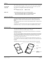
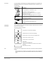
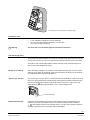
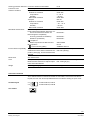
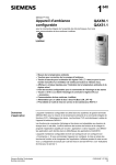
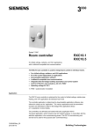
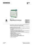
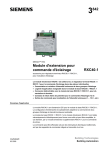
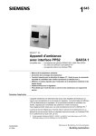
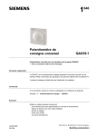
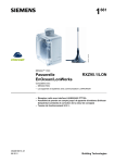
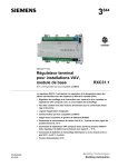
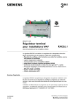
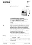
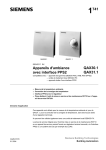
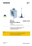
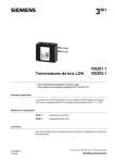
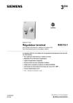
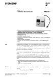
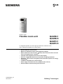
1 648 Desigo™ RXC Flexible room unit QAX50.1 QAX50.5 QAX51.1 QAX51.5 for integrated operation of HVAC, lighting and blinds in individual rooms; with LONMARK®-compatible bus communication • • • • • • • • • CA2N1648en_04 05.03.2012 Room temperature measurement Buttons for adjustment of the room temperature setpoint Rocker switch for mode selection ( / Auto) and for manual control of the fan in fan-coil systems (up to 3 speeds) LCD with room temperature and control mode display Panel for configurable buttons for the operation of lighting and blinds Off-button ( ), to switch room lighting off and set HVAC system to an energysaving mode LONMARK®-compatible bus communications Power supply via the two-wire bus (LONWORKS® bus, LPT-10) Socket for RXT10 commissioning and service tool Building Technologies Use The flexible room unit is used in conjunction with the Desigo RXC room automation system for measurement of the room temperature and for integrated operation of HVAC, lighting and blinds. The HVAC functions are identical to those of the QAX34.1 room unit. The functions for operating lighting and blinds can be configured flexibly to match the requirements in the room. This involves fitting the required rocker switches and downloading the associated application software (referred to further on as the “application”). The various applications are described individually in the Desigo RXC Applications library, CA2A3810 (V1) or CA110300 (V2). The flexible room unit is delivered in its unconfigured state (see “Ordering”). The room units must be fitted with buttons/rocker switches and loaded with the application at the commissioning stage. The latter process is carried out with the RXT10 commissioning and service tool (see “Commissioning notes”). Type summary The flexible room unit is available in two basic versions, which differ only in the number and type of buttons/rocker switches supplied. 80067 A QAX50 2x 4x + 3x 4x 1x 2x 80068 A QAX51 2x 1x + 4x 3x 1x 3x Type QAX50 is used for all applications involving on/off lighting control. Type QAX51 is required for dimmer control. Product No. Stock number Designation QAX50.5/C000 S55623-H114 Flexible room unit (on/off lighting control) QAX51.5/C000 S55623-H115 Flexible room unit (dimmer control) 2/10 Siemens Building Technologies QAX50, QAX51 – Flexible room unit CA2N1648en_04 05.03.2012 Ordering When ordering, please specify the quantity, product name, type code and configuration. Unconfigured room units Unconfigured units are available only in the basic versions shown under “Type summary” above. The configuration code for these units is C000. Example: 7 Flexible room units Button sets QAX51.5 / C000 The two different button sets can also be ordered separately: • • Set A: SAP ordering No. 4268 277 30 (on/off lighting control) Set B: SAP ordering No. 4268 277 40 (dimmer control) Equipment combinations The QAX50 and QAX51 are primarily used in conjunction with the RXC30 / RXC31 / RXC38 room controllers and the associated extension modules, types RXC40 and RXC41. The room units are also used in conjunction with the RXC20, RXC21, or RXC22 for fancoil applications. The flexible room units can also be used for the control of lighting and blinds (and to a limited extent HVAC) in conjunction with LONMARK®-compatible third-party devices. Mechanical design The room unit is designed for mounting on a recessed conduit box. The bus cable is connected to the unit from the rear with a plug-in connection. Essentially, the flexible room units comprise a housing and base unit, connected by releasable snap-fittings. The housing accommodates a printed circuit board, room temperature sensor element, buttons for setpoint adjustment, mode selection and fan-speed control, the LCD panel, a configurable control panel, a plug-in connector for the bus and a socket for the RXT10 commissioning and service tool. The configurable control panel incorporates two rubber membranes and a total of 10 contact points. The contacts are operated by the buttons and rocker switches fitted into the panel. The flexible room unit has a plastic housing and a galvanized steel mounting plate. Mounting plate 80075 Housing Plug-in connector for bus Socket for commissioning and service tool 3/10 Siemens Building Technologies QAX50, QAX51 – Flexible room unit CA2N1648en_04 05.03.2012 Operator controls and display 80069 A Buttons for adjustment of the room temperature setpoint Room temperature and control sequence (heating / cooling) display Display of current control mode or current fan speed Rocker switch for selection of control mode and fan speed Configurable control panel (example of configuration) Note The actual functions of the operator controls and display panel are determined by the downloaded application. The description below covers all the possible options. Rocker switch for mode selection and fan-speed control The control mode of the connected room controller can be selected with the rocker switch. The same switch is used for manual control of the up to three fan speeds. Pressing once in the direction of the left arrow switches one stage to the left, and pressing once in the direction of the right arrow switches one stage to the right. The current control mode or manually-selected fan speed is indicated in the display panel by a horizontal bar below the associated symbol. Position Fan speed control 1) Fan controlled automatically by room controller Fan controlled automatically by room controller Manual, fan speed 1 Control mode 1) Pre-comfort or Economy (according to central control) Comfort Manual, fan speed 2 Manual, fan speed 3 1) For function descriptions of the relevant HVAC applications refer to the Desigo RXC Applications library, CA2A3810 (V1) or CA110300 (V2). Note The operation of this rocker switch has no effect on the control of lighting or blinds. Buttons for room temperature setpoint adjustment Press the button once to switch from a display of the current room temperature to a display of the setpoint. Each further operation of the + or – button raises or lowers the setpoint by 0.5 K or 1.0 °F. The unit of measurement and the maximum allowable adjustment range is determined by parameters in the application software. 4/10 Siemens Building Technologies QAX50, QAX51 – Flexible room unit CA2N1648en_04 05.03.2012 LCD display In normal operation, the following may be displayed (depending on the application parameters) For details refer to the Desigo RXC Applications library, CA2A3810 (V1) or CA110300 (V2).: Display element (examples) Description Room temperature in °C (resolution 0.5 °C) Room temperature in °F (resolution 1.0 °F) Digital display of setpoint adjustment (displayed only while relative adjustment is in progress). Digital display and scale (displayed only while absolute adjustment is in progress) Control sequence: Cooling Control sequence: Heating Room units with mode and fan-speed selection enabled: Fan speed 1: ON In room units allowing mode selection only: Auto: ON Configurable control panel The configurable control panel can be fitted according to requirements with a variety of buttons and rocker switches. The following options are available: Large button for on/off control of lighting Standard button for on/off control of lighting Rocker switch for on/off control of two lighting units Rocker switch for dimmer control Rocker switch for control of blinds OFF button: Switches all room lighting off Switches the connected room controller to Pre-comfort or Economy Blank plate (no function) Note Flexible room units configured with an OFF button incorporate the following additional function: If the connected room controller is in Pre-comfort or Economy mode, it will switch to Comfort as soon as any of the rocker switches or buttons on the room unit are operated. 5/10 Siemens Building Technologies QAX50, QAX51 – Flexible room unit CA2N1648en_04 05.03.2012 80096 A Removing the buttons/rocker switches “Search” LED There are two LEDs under the top button/rocker switch on the configurable control panel. These remain permanently on so that the unit can be located more easily in the dark. “Service” LED The yellow “Service” LED is fitted under the last button/rocker switch on the configurable panel and indicates the status of the room unit by means of different flashing patterns (see the RXT10 user manual, CM110669). Disposal The devices are classified as waste electronic equipment in terms of the European Directive 2002/96/EC (WEEE) and should not be disposed of as unsorted municipal waste. The relevant national legal rules are to be adhered to. Regarding disposal, use the systems setup for collecting electronic waste. Observe all local and applicable laws. Engineering notes The flexible room unit is connected to the LONWORKS® bus by a two-wire twisted cable and receives its power via the bus cable. This cable must be connected to a central bus power supply in accordance with LPT-10 (see the Installation guide, CA110334). For mounting, a standard recessed conduit box or an aperture of the equivalent size is required. Mounting notes • • • • The room unit must be mounted on a recessed conduit box Mount on a flat surface with a maximum offset of 1 mm The base plate should be fixed with screws, max. diameter 3.5 mm Do not mount in recesses, shelves, behind curtains or doors, or above or near heat sources. • Avoid exposure to direct sunlight or draughts. • The electrical wiring conduit must be sealed where it joins the room unit, to prevent the occurrence of draughts in the conduit which could affect the sensor. • The specified ambient conditions must be complied with. Mounting instructions are printed on the room unit packaging. 6/10 Siemens Building Technologies QAX50, QAX51 – Flexible room unit CA2N1648en_04 05.03.2012 80091 A 1 2 Fit to top rail (1) and snap-mount on bottom rail (2) Installation notes • • • STOP Warning Local installation regulations must be observed. Do not route mains voltage cables to the conduit box. Use only the original bus plug. The room unit is not protected against connection to AC 230 V. Commissioning notes The QAX50 and QAX51 flexible room units are commissioned with the RXT10 commissioning and service tool. This is connected to the LONWORKS® bus via the tool socket. The RXT10 user manual (CM110669) contains a step-by-step commissioning procedure for the entire Desigo RXC range. Response on start-up When the supply voltage is connected (via the LONWORKS® bus) the room unit runs a self-test, during which all segments of the LCD are enabled. At the end of the self-test, the LCD panel reverts to the normal display. “Service pin” function The “service pin” function, which is used to transmit the identification number of the unit to the bus can be enabled by simultaneously pressing the two setpoint adjustment buttons and the mode selection/fan-speed rocker switch (to the left or right). The LCD for approximately 1 to 2 s in acknowledgement. panel displays 80112 Press simultaneously Wink function display If the RXT10 commissioning and service tool is used to issue an identification command to in the room unit (wink function), the LCD panel responds with the display . This display persists for a maximum of 64 s or until a rocker switch or button is operated. The room unit then reverts to the normal display. 7/10 Siemens Building Technologies QAX50, QAX51 – Flexible room unit CA2N1648en_04 05.03.2012 Notes on operation During normal operation and commissioning, the LCD panel also serves to display error messages: Display Description Room temperature sensor outside range 0 ... 40 °C Technical data Power supply Function data Interfaces Cable connection Operating voltage SELV / PELV Max. DC 42 V The Room unit receives its power via the LONWORKS® bus in accordance with specification LPT-10 Power consumption Max. 0.3 W Temperature sensor Measuring element NTC resistor Measuring range 0 ... 40 °C Response time ≤ 9 min Measuring accuracy (5 ... 30 °C) ± 0.5 K Measuring accuracy (25 °C) ± 0.25 K Setpoint correction Correction range (defined by application Max. ± 10 K (default ± 3 K) parameters) Display Type LCD − Room temperature Functions displayed − Setpoint adjustment − Operating status − Manually selected fan speed − Control sequence (heating / cooling) Configurable operator panel Number of contact points 10 Max. number of buttons/rocker switches 5 − On/off control of lighting Functions − Lighting dimmer control − Blinds up/down and adjustment of slat angle − OFF button LONWORKS® bus Interface type LONMARK®-compatible LPT-10 Transceiver Baud rate 78 kBit/s Bus topology and bus termination See Installation guide, CA110334 Connection terminals (plug-in screw terminals)Solid or stranded conductors 2 x 1.0 mm2 Single cable lengths See also Installation guide, CA110334 Max. 500 m LONWORKS® bus Cable type See Installation guide, CA110334 Tool connecting cable Max. 3 m (manufactured) 8/10 Siemens Building Technologies QAX50, QAX51 – Flexible room unit CA2N1648en_04 05.03.2012 Housing protection standard Protection standard to EN 60529 Protection class Insulation protection class Ambient conditions Operation Ambient air conditions Temperature Humidity Mechanical conditions Transport Ambient air conditions Temperature Humidity Mechanical conditions Standards and directives Product safety Product standard Automatic electronic controls for household and similar use Electromagnetic compatibility Immunity (industrial & residential) Emissions (residential) compliance Meets requirements of EMC directive UL compliance C-Tick conformity (EMC) IP 30 III IEC 721 Class 3K5 0 ... 50 °C < 85 %rh Class 3M2 IEC 721 Class 2K3 – 25 ... 70 °C < 95 %rh Class 2M2 EN 60730-1 EN 60730-1 EN 60730-1 2004/108/EC UL916 AS/NZS 61000-6-3 Environmental compatibility The product environmental declaration ISO 14001 (Environment) CA2E1648 contains data on materials com- ISO 9001 (Quality) position, packaging, environmental benefit, disposal Dimensions Color See "Dimensions" Front plate and operator control panel Buttons/rocker switches for setpoint adjustment and mode selection Excluding packaging Weight NCS S 0502-G, ≈ RAL 9003 signal white RAL 7035 light grey 0.175 kg Connection terminals The LONWORKS® bus connection terminals are removable, so that if the bus cable is looped, the room unit can be separated from the bus without causing an open circuit. Terminal layout LONWORKS® bus, Data A LONWORKS® bus, Data B CLA CLB Tool socket CLA CLB 9/10 Siemens Building Technologies QAX50, QAX51 – Flexible room unit CA2N1648en_04 05.03.2012 Dimensions All dimensions in mm 10/10 2000 - 2012 Siemens Switzerland Ltd. Siemens Building Technologies QAX50, QAX51 – Flexible room unit Subject to change CA2N1648en_04 05.03.2012