1
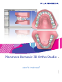
Planmeca Romexis 3D Ortho Studio
®
EN
user's manual
10033024_1
TABLE OF CONTENTS
1
INTRODUCTION ................................................................................................................. 1
2
STARTING A NEW CASE FROM PLANMECA ROMEXIS ................................... 2
3
CONTINUING WITH AN EXISTING CASE IN PLANMECA ROMEXIS 3D
ORTHOSTUDIO ...............................................................................................7
4
USER INTERFACE ............................................................................................................. 8
4.1
4.2
4.3
5
Visualization area ........................................................................................................... 8
Main toolbar ................................................................................................................... 9
View toolbar ................................................................................................................. 10
ADDING AND EDITING DATA ENTRIES .................................................................13
5.1
5.2
5.3
5.4
Adding new entries ...................................................................................................... 13
Assigning doctors with clinics ...................................................................................... 14
Assigning patients with doctors .................................................................................... 14
Editing clinic, doctor and patient data .......................................................................... 15
6
IMPORTING CASES ........................................................................................................16
7
PREPARING AND ADJUSTING DENTAL MODELS ............................................17
7.1
7.2
7.3
7.4
7.5
8
DENTAL MODEL ANALYSIS .......................................................................................24
8.1
8.2
8.3
8.4
8.5
9
Occlusion visualization ................................................................................................. 24
Cross section analysis ................................................................................................. 25
Teeth measurements ................................................................................................... 26
Measuring arch length ................................................................................................. 28
Free measurements ..................................................................................................... 29
TREATMENT PLANNING IN 3D VIRTUAL SETUP ..............................................30
9.1
9.2
9.3
10
Adjusting the orientation of the models ........................................................................ 17
Adjusting teeth articulation ........................................................................................... 18
Smoothing and sculpting the models ........................................................................... 19
Adding virtual base ...................................................................................................... 20
Removing extra surface material from the models using cut and close ....................... 23
Tooth segmentation ..................................................................................................... 30
Virtual setup ................................................................................................................. 33
Creating a series of digital dental models using models builder .................................. 42
GENERAL MENUS ...........................................................................................................45
10.1
10.2
10.3
10.4
File menu ..................................................................................................................... 45
Help menu .................................................................................................................... 45
Snapshot menu ............................................................................................................ 45
Settings menu .............................................................................................................. 46
User’s Manual
Planmeca Romexis 3D Ortho Studio TOC-1
TABLE OF CONTENTS
The manufacturer, assembler, and importer are responsible for the safety,
reliability and performance of the unit only if:
- installation, calibration, modification and repairs are carried out by qualified
authorized personnel
- electrical installations are carried out according to the appropriate
requirements such as IEC 60364
- equipment is used according to the operating instructions.
Planmeca pursues a policy of continual product development. Although
every effort is made to produce up-to-date product documentation this
publication should not be regarded as an infallible guide to current
specifications. We reserve the right to make changes without prior notice.
COPYRIGHT PLANMECA
Publication number 10033024 Revision 1
Released 14 June 2013
TOC - 2 Planmeca Romexis 3D Ortho Studio
User’s Manual
INTRODUCTION
1
INTRODUCTION
The Planmeca Romexis 3D Ortho Studio is a software module designed for orthodontists and
dental laboratories. It can be used for preparation of digital dental models, making dental
model analyses, treatment planning in 3D virtual setup, and export of digital dental models in
STL format.
This manual describes how to use the Planmeca Romexis 3D Ortho Studio software.
NOTE
Read this manual carefully before using the system.
NOTE
This manual is valid for the following software revisions:
Planmeca Romexis 3.2.R.
NOTE
Planmeca Romexis 3D Ortho Studio can be used with Microsoft Windows 8, 7, XP,
Vista Business, Windows 2003 and Windows 2008 Server operating systems.
Planmeca Romexis conforms to Windows user interface standards.
NOTE
User organization must take care of protecting the computer and the network by using
up-to-date virus and malware protection software and fire wall.
NOTE
If necessary save the following for backup of ortho studio data:
C:\Program Files\Planmeca\Romexis\client\orthostudio\
NOTE
In order to use the software Planmeca Romexis 3D Ortho Studio USB license dongle
has to be inserted into the client computer USB port.
NOTE
The software is created by AGE Solutions S.r.l.
User’s Manual
Planmeca Romexis 3D Ortho Studio 1
STARTING A NEW CASE FROM PLANMECA ROMEXIS
2
STARTING A NEW CASE FROM PLANMECA ROMEXIS
The following procedure describes how to align digital dental models captured with Planmeca
Promax 3D model scanning program and transfer the models in occlusion to Planmeca
Romexis 3D Ortho Studio as a new case.
1. Take an exposure of both the mandibular and maxillary models using the Planmeca Promax
3D model scanning scan program selecting Model capture from Planmeca Romexis.
NOTE
For full details on how to use the Planmeca Promax 3D model scanning program refer
to your Planmeca X-ray unit user’s manual.
2. Take an exposure of the bite index using the Planmeca Promax 3D model scanning program
of your Planmeca X-ray unit selecting 3D capture from Planmeca Romexis.
The image of the bite index is in DICOM format and the mandibular and maxillary models are
in STL format.
3. Open the upper model from the Planmeca Romexis Volumes list.
The model opens in Romexis ProFace/Surface module
4. Select the Paint ROI to trim tool.
5. Mark the area to trim on the image.
2
Planmeca Romexis 3D Ortho Studio
User’s Manual
STARTING A NEW CASE FROM PLANMECA ROMEXIS
When the trimming is completed the marked area will be automatically removed from the
image.
6. Repeat the procedure for the lower model from steps 3 to 5.
7. Open the image of the bite index from the Volumes tab.
8. Click IO-Scan import button.
9. Open the digital impressions one by one by clicking the Select button.
User’s Manual
Planmeca Romexis 3D Ortho Studio 3
STARTING A NEW CASE FROM PLANMECA ROMEXIS
10.Select first the UPPER model and click OK.
11.Lower the threshold value as much as possible (down to 100) to better visualize the bite index
surface.
To zoom in / out the image scroll the mouse wheel.
12.Mark the corresponding points on both the model and the index by right-clicking on the
corresponding areas. The points are colour-coded (red, green and blue) so that it is easier to
see which point in the index corresponds to which point in the model.
4
Planmeca Romexis 3D Ortho Studio
User’s Manual
STARTING A NEW CASE FROM PLANMECA ROMEXIS
NOTE
Make sure that you have selected the correct occlusion side from both the model and
the bite index. Note that the model and bite index are each other’s mirror images.
13.Click Done.
14.Repeat the steps from 8 to 13 selecting the lower model in the Import STL dialogue.
15.Launch the models in Planmeca Romexis 3D Ortho Studio by clicking the Ortho Studio icon.
Patient data (patient ID, first and last name, date of birth) is automatically transferred to
Planmeca Romexis 3D OrthoStudio as a new case under default clinic and default doctor.
NOTE
Close the Planmeca 3D Ortho Studio before starting the transfer.
NOTE
The models are always transferred to Planmeca Romexis 3D Ortho Studio as new
models when the quick launch button is pressed. For continuing a previous case see
section “CONTINUING WITH AN EXISTING CASE IN PLANMECA ROMEXIS 3D
ORTHOSTUDIO” on page 7.
16.To adjust the orientation of the models click Yes.
17.Select either mandibular or maxillary model.
User’s Manual
Planmeca Romexis 3D Ortho Studio 5
STARTING A NEW CASE FROM PLANMECA ROMEXIS
18.Mark the three points on the model.
19.Select another model (mandibular or maxillary) and mark the three corresponding points on
the model.
20.Click Next.
If necessary fine-tune the orientation of the models and the occlusal plane by moving the
coloured arrows.
6
Planmeca Romexis 3D Ortho Studio
User’s Manual
CONTINUING WITH AN EXISTING CASE IN PLANMECA ROMEXIS 3D ORTHOSTUDIO
3
CONTINUING WITH AN EXISTING CASE IN PLANMECA
ROMEXIS 3D ORTHOSTUDIO
NOTE
If the models have been already aligned and transferred to Planmeca 3D Ortho Studio
you can start from this section. If you need to align the models and the bite index see
section “STARTING A NEW CASE FROM PLANMECA ROMEXIS” on page 2.
1. Click the OrthoStudio icon on your desktop.
2. In the following window click the Open case icon.
3. Select the existing case from the tree view under default clinic and doctor and the patient in
question.
To view all the cases of the selected patient click the Select patient icon.
If necessary you can modify the clinic, doctor and patient data and add a new clinic, doctor
and patient.
To move a case to another patient click the case in the tree and drag it to the patient folder
where you’d like to move the case to.
4. Click Next.
The case opens in the following window.
User’s Manual
Planmeca Romexis 3D Ortho Studio 7
USER INTERFACE
4
USER INTERFACE
The Planmeca Romexis 3D Ortho Studio user interface consists of the following elements:
•
Visualization area
•
Main tool bar
•
View tool bar (for viewing the object from different directions)
•
Bottom tool bar
•
Info field
Main
toolbar
Visualization
area
View toolbar
Info
field
Bottom toolbar
4.1
Visualization area
The images and models are opened and edited in the visualization area
In the visualization area it is possible to create virtual bases, show the occlusion visualization
between maxillary and mandibular arches, measure distance between teeth and perform
virtual setup.
To view and examine the models displayed in the visualization / editing area you can set
camera parameters (position, scale and rotation) using the instrument trackball tool.
To rotate around the model use the left mouse button.
To Zoom in / out scroll the mouse wheel.
To move (pan) the camera use the right mouse button
The info area of the screen shows the info related to the current Case. In particular the info
about clinic, Doctor and Patient are displayed, also with the Case ID.
8
Planmeca Romexis 3D Ortho Studio
User’s Manual
USER INTERFACE
4.2
Main toolbar
4.2.1
Home tab
New case
See sections 6 “IMPORTING CASES” on page 16 and 5 “ADDING AND EDITING DATA
ENTRIES” on page 13.
Open (existing) case
See section 3 “CONTINUING WITH AN EXISTING CASE IN PLANMECA ROMEXIS 3D
ORTHOSTUDIO” on page 7.
Save case
Click this button to save the case you are currently working on.
Exports
•
Stl exports
Exports the case data and the maxillary and mandibular models in *.Stl file format.
•
Ortho export
Exports the case in *.ortho file format.
Change Local Origo
Use this tool to adjust the orientation of the models, see page 17.
Change Articulation
See section 7.2 “Adjusting teeth articulation” on page 18.
Add Virtual Base
See section 7.4 “Adding virtual base” on page 20.
Sculpting
See section 7.4 “Adding virtual base” on page 20
User’s Manual
Planmeca Romexis 3D Ortho Studio 9
USER INTERFACE
4.3
View toolbar
Multiple Views
Front view
Rear view
Right side view
Left side view
Top view
Bottom view
Open mouth
Close mouth
Show maxillary/mandibular/all
Show mandibular/all
Show all
Change the view from maxillary to mandibular or to all. Changing the view from all to maxillary
or vice versa enables or disables some features of the software.
Exit the software
10
Planmeca Romexis 3D Ortho Studio
User’s Manual
USER INTERFACE
4.3.1
Analyses and measurements tab
Occlusion visualization
Calculates the distances between maxillary and mandibular arches. See section 8.1
“Occlusion visualization” on page 24.
Cross sections
See section 8.2 “Cross section analysis” on page 25
Teeth measurements
See section 8.3 “Teeth measurements” on page 26
Arch measurements
See section 8.4 “Measuring arch length” on page 28
Free measurements
See section 8.5 “Free measurements” on page 29
4.3.2
Virtual setup tab
Tooth segmentation menu
•
Tooth segmentation: draw an outline for each tooth
•
Cutting line: separates the tooth from the gum and combines the outlines of separated
neighbouring teeth. The maximum distance under which the outlines of the adjacent teeth are
automatically combined can be freely defined.
•
Change local origo: adjust local origo, axes and root for each tooth.
Virtual setup
See section 9.2 “Virtual setup” on page 33.
Models builder
See section 9.3 “Creating a series of digital dental models using models builder” on page 42.
Cut and close
See section 7.5 “Removing extra surface material from the models using cut and close” on
page 23.
Menu list of all virtual models
Show/hide attachments, brackets, brackets key, labels
Animation
User’s Manual
Planmeca Romexis 3D Ortho Studio 11
USER INTERFACE
Exports
PDF Exports
Exports the treatment plan report in PDF format.
Xls Exports
Exports the treatment plan report in MS Excel format (.xls).
4.3.3
Bottom toolbar
The bottom toolbar contains tool for adjusting the visual settings of the viewing area.
Zoom in
Zoom out
Show/hide trackball
Reset trackball [Key R]
Parallel projection [Key O]
Perspective projection [Key P]
Smooth shading [Key S]
Flat shading [Key F]
Show/hide triangles [Key E]
Show/hide edges [Key E]
Show/hide vertices [Key V]
12
Planmeca Romexis 3D Ortho Studio
User’s Manual
ADDING AND EDITING DATA ENTRIES
5
ADDING AND EDITING DATA ENTRIES
5.1
Adding new entries
1. Click the New Case icon on the main toolbar.
To add a new clinic click this button.
2. Fill in the necessary data.
3. Save the clinic to the database by clicking this icon at the bottom of the screen.
To clear the form click Clear.
To add a new doctor click the Add new doctor button and fill in the necessary data.
To add a new patient click the Add new patient button and fill in the necessary data.
4. Select the clinic from the drop-down menu.
To delete the clinic currently selected click the Delete icon.
NOTE
User’s Manual
Clicking the Delete icon removes the selected clinic from the Planmeca Romexis
Database.
Planmeca Romexis 3D Ortho Studio 13
ADDING AND EDITING DATA ENTRIES
5.2
Assigning doctors with clinics
To add a new doctor to a clinic select a doctor from the Other doctors drop-down menu and
click the Add icon.
To remove a doctor from the list of Doctors associated with a certain clinic without deleting
the doctor from the database clicking the Delete button next to Doctor drop-down menu.
To delete a doctor from the database select the doctor from the Other Doctors menu and click
Delete.
NOTE
Clicking the Delete icon removes the selected doctor from the Planmeca Romexis 3D
Ortho Studio database.
5.3
Assigning patients with doctors
To assign a new patient to the currently selected doctor select the patient from the Other
patients drop-down menu and click the Add button.
To remove a patient associated with a certain doctor without deleting the patient from the
database select the patient and click the Delete button next to Patient drop-down menu.
To remove the patient from the database click the Delete button next to the Other patients
drop-down menu.
NOTE
14
Clicking the Delete icon removes the selected patient and all its data from the
Planmeca Romexis 3D Ortho Studio database.
Planmeca Romexis 3D Ortho Studio
User’s Manual
ADDING AND EDITING DATA ENTRIES
5.4
Editing clinic, doctor and patient data
To edit clinic, doctor and patient data click the respective drop-down menu and fill in the
necessary data.
When finished click the Next icon to proceed to dental model import for the current patient
see section 6 “IMPORTING CASES” on page 16.
User’s Manual
Planmeca Romexis 3D Ortho Studio 15
IMPORTING CASES
6
IMPORTING CASES
1. Click the New case button.
•
To import a case for an existing patient select the patient from the drop-down menu.
•
To import a case for a new patient first add the necessary data entries see section 5.1
“Adding new entries” on page 13.
2. Click Next.
3. Import the models from an external folder either in:
•
stl file format by clicking the Open files from disk icon
or in
•
ortho file format: click the Import icon.
4. After successful import the following window appears. Click OK.
5. To start preparing models continue to section 7 “PREPARING AND ADJUSTING DENTAL
MODELS” on page 17.
16
Planmeca Romexis 3D Ortho Studio
User’s Manual
PREPARING AND ADJUSTING DENTAL MODELS
7
PREPARING AND ADJUSTING DENTAL MODELS
7.1
Adjusting the orientation of the models
If necessary you can adjust the orientation of the models as follows.
1. Click this icon.
2. Indicate three points on the model by double-clicking with the left mouse button on the points
shown in the help image on the left. Click Next.
3. Select the maxillary model and repeat the same step. Click Next.
4. Translate and rotate the models by dragging the coloured arrows or circle lines, until the
models are correctly orientated.
•
the centre marks the origin of the coordinate system
•
the red arrow marks the X axis
•
the green arrow marks the Y axis
•
blue arrow marks the Z axis
5. To update the local origo click Next.
6. Click Save.
User’s Manual
Planmeca Romexis 3D Ortho Studio 17
PREPARING AND ADJUSTING DENTAL MODELS
7.2
Adjusting teeth articulation
If necessary you can adjust the contact relationship of the occlusal surfaces of the teeth
during jaw movement.
1. Click this icon.
2. In the following window adjust the articulation by moving the arrows.
•
the centre marks the origin of the coordinate system
•
the red arrow marks the X axis
•
the green arrow marks the Y axis
•
blue arrow marks the Z axis
3. To update the articulation click Next.
4. Click Save.
18
Planmeca Romexis 3D Ortho Studio
User’s Manual
PREPARING AND ADJUSTING DENTAL MODELS
7.3
Smoothing and sculpting the models
The sculpting and smoothing tools can be used to remove artifacts and excess material from
the digital dental models and to smooth the surface of the models.
In order to make some modifications on the models, click the Sculpting icon.
Add\remove material
Click this icon to add or remove material from the surface of the models. Adjust the size,
amplitude of the brush and Maximum amount of material to be removed.
Smooth surface
Click this icon to smooth the surface of the models. Adjust Size and Amplitude of the brush.
Size of the smoothing tool
Undo/redo
Use these buttons to undo and redo operations.
User’s Manual
Planmeca Romexis 3D Ortho Studio 19
PREPARING AND ADJUSTING DENTAL MODELS
7.4
Adding virtual base
To add the virtual base for maxillary and mandibular models click the Add virtual base icon.
7.4.1
Defining the cutting line
The cutting line needs to be defined for the models so that they can be later used as base
lines for the virtual bases.
To add control points on the line:
1. Press and hold down the Shift key while clicking/double-clicking or dragging with the left
mouse button.
2. When finished click Next.
3. In the following window adjust the size and distance of the base in relation to the models by
pressing and holding down the Shift key while dragging the base from the arrows with the left
mouse button.
20
Planmeca Romexis 3D Ortho Studio
User’s Manual
PREPARING AND ADJUSTING DENTAL MODELS
4. Select the type of the virtual base (Parallel, ABO, Tweed, Ricketts) from the drop-down menu
on the lower left corner of the screen.
Changing shape of virtual base border
To change the shape of the virtual base border drag the points at the virtual base border.
To add/remove points use hold down the Shift key while double-clicking with the left mouse
button.
To draw the base border hold down the Shift key and click with the left mouse button
dragging near to the base border.
To move the border up and down drag the arrows of the virtual base border.
Changing shape of virtual base
To change the shape (width and length) of the virtual base drag the points and arrows at the
corners of virtual base.
During editing constraints between angles/sides of base are preserved.
Changing virtual base height
To change the height of virtual bases drag the arrow at the bottom of the base. This option is
disabled for ABO bases.
To edit both bases simultaneously check the Symmetrical changes check box.
When finished click the Next icon.
The defined bases will be merged with maxillary and mandibular models.
User’s Manual
Planmeca Romexis 3D Ortho Studio 21
PREPARING AND ADJUSTING DENTAL MODELS
Editing
base height
Editing
base shape
Editing
base border
shape
22
Planmeca Romexis 3D Ortho Studio
User’s Manual
PREPARING AND ADJUSTING DENTAL MODELS
7.5
Removing extra surface material from the models using cut
and close
Using the Cut and close tool any excess material can be removed from the digital models by
indicating a plane under which all the material is cut off. This way the material can be saved
when printing the models with a 3D printer.
1. Select the arch using the Show Maxillary or Show Mandibular icon.
2. Click the Cut and Close icon.
3. Rotate the plane with the green circles and rotate the plane with the red arrows.
4. To cut off all material below the indicated plane from all virtual models click the Next icon.
User’s Manual
Planmeca Romexis 3D Ortho Studio 23
DENTAL MODEL ANALYSIS
8
DENTAL MODEL ANALYSIS
8.1
Occlusion visualization
This tool can be used to view and analyse the occlusion distance (in millimetres) between
maxillary and mandibular arches.
1. Click the Occlusion visualization icon.
The colours on the arch represent the occlusion distance between the teeth on maxillary and
mandibular arch.
2. To view the occlusion distance at the exact point on the arch double-click at the point where
you would like to view the distance.
3. The colour scale is displayed at the right side of the screen.
NOTE
The distance can be shown only on the colored areas.
The occlusion distance is visualized on both models.
To show the occlusion distance on both arches with mouth open click the Open mouth icon.
To show the occlusion distance only on the maxillary arch click the Show Maxillary icon.
To show the occlusion distance only on the mandibular click the Show Mandibular icon.
24
Planmeca Romexis 3D Ortho Studio
User’s Manual
DENTAL MODEL ANALYSIS
8.2
Cross section analysis
In the cross section analysis 2D measurements can be done on cross sectional plane aligned
to one of the main axis. The cross sectional plane can be slid through the model.
1. Click the Cross Sections icon.
2. To change the plane and the transparency of the model use the Move plane and Dental
model icon slides.
To add a point into a 2D grid double-click it with the left mouse button.
To pan the cross sectional grid, right-click and drag it.
To zoom in and out scroll the mouse wheel.
To save a measurement view click the plus icon on the left side of the screen after making the
measurement, and click the Next icon.
User’s Manual
Planmeca Romexis 3D Ortho Studio 25
DENTAL MODEL ANALYSIS
8.3
Teeth measurements
1. Select the arch you want to measure by clicking the Show Maxillary or Show Mandibular
icon.
2. Click this icon.
To start making the measurements tooth by tooth:
3. Starting from the most posterior tooth on the left side of the dental arch double-click on the
distal and mesial points of each tooth with the left mouse button.
4. If necessary correct the tooth number via the drop-down menu next to the tooth
measurement.
For each tooth width measurement the current length is shown. To adjust length drag either of
the two points with the left mouse button.
26
Planmeca Romexis 3D Ortho Studio
User’s Manual
DENTAL MODEL ANALYSIS
The total and average length of the segments are shown in the dental map on the left side of
the screen.
When all tooth measurements of the upper and lower arches are done, Bolton overall and
anterior ratio are shown in the upper part of the screen.
Use these icons to Undo / Redo tasks.
To clear the measurement click the Reset icon.
To save the measurement click the Next icon and then the Save case icon.
User’s Manual
Planmeca Romexis 3D Ortho Studio 27
DENTAL MODEL ANALYSIS
8.4
Measuring arch length
1. Select the arch to measure by clicking the Show Maxillary or Show Mandibular icon.
2. Click the Measure arch icon.
3. Mark three points on the arch by clicking with the left mouse button.
28
NOTE
Mark first point on the side, the second one in front and the third one on the other side.
NOTE
If necessary more than 3 points can be added by double- clicking on the blue line with
the left mouse button.
Planmeca Romexis 3D Ortho Studio
User’s Manual
DENTAL MODEL ANALYSIS
8.5
Free measurements
To freely measure lengths or angles on the models:
1. Click on the Free measurement icon.
2. Select the arch to measure by clicking the Show Maxillary or Show Mandibular icon.
3. Select Distance or Angle measurements and the appropriate measuring unit.
4. Mark a point on the arch by double-clicking with the left mouse button.
User’s Manual
Planmeca Romexis 3D Ortho Studio 29
TREATMENT PLANNING IN 3D VIRTUAL SETUP
9
TREATMENT PLANNING IN 3D VIRTUAL SETUP
The virtual setup can be used for making a staged treatment plan e.g. by displacing, rotating
and extracting teeth. The plan can then be utilized in the models builder for creating a series
of STL models of the treatment plan.
9.1
Tooth segmentation
The tooth segmentation consist of defining outlines for single teeth, combining teeth outlines
and defining local origo for all teeth.
1. Select the arch to use for segmentation by clicking the Show Maxillary or Show Mandibular
icon.
NOTE
Tooth measurements have to be done before the segmentation of the teeth.
2. Click the Tooth Segmentation icon.
3. To mark the outlines of the tooth double-click with the left mouse button on all four directions
(distal, buccal, mesial, lingual).
The software automatically combines the points by drawing a line between them.
30
Planmeca Romexis 3D Ortho Studio
User’s Manual
TREATMENT PLANNING IN 3D VIRTUAL SETUP
To fine-tune tooth margin line:
•
move a point on the outline by dragging it using the left mouse button
•
remove a point from the outline by double-clicking on it with the left mouse button
•
add a point between two points on the outline by double-clicking on the outline
•
add a new point by clicking the Undo button and clicking on another spot in the outline area.
4. To define the outlines for all teeth repeat the procedure from step 3 on page 30.
5. When you have defined the outlines for all teeth verify that the teeth are correctly outlined.
To readjust the outlines you can:
•
add a new point between two consecutive points by double-clicking near the edge of the two
points.
•
remove a point by double-clicking on it
•
move a point by clicking and dragging it using the left mouse button.
•
define the maximum distance between the outlines of adjacent tooth to be combined using
the Join slider.
If you need to re-define the outlines return to step 3 on page 30.
6. To continue to definition of local origo click Next.
User’s Manual
Planmeca Romexis 3D Ortho Studio 31
TREATMENT PLANNING IN 3D VIRTUAL SETUP
NOTE
Before proceeding complete the cutting line procedure.
7. From the Tooth segmentation menu select Change local origo.
8. Double-click on the tooth and use the manipulator to change the origo if necessary.
The tooth axis orientations should be based on the tooth root directions.
NOTE
When changing the local origo, the virtual root of the tooth changes direction.
To change the root dimension select the tooth and use the left toolbox.
32
Planmeca Romexis 3D Ortho Studio
User’s Manual
TREATMENT PLANNING IN 3D VIRTUAL SETUP
9.2
Virtual setup
1. Click the Virtual Setup icon.
2. Select a tooth by clicking it with the left mouse button.
9.2.1
Displacement of teeth
Translating tooth
1. Click the tooth with the left mouse button.
2. Press and hold down the Shift key while dragging the teeth with the left mouse button.
Rotating tooth
Press and hold down the Ctrl key while dragging the tooth with the left mouse button.
If a tooth is selected a Tooth manipulator can be activated to control the movements of the
tooth.
User’s Manual
Planmeca Romexis 3D Ortho Studio 33
TREATMENT PLANNING IN 3D VIRTUAL SETUP
9.2.2
Adding layers
Layers can be created for simulation of different stages of treatment.
For example if the posterior teeth need to be moved first you can build Layer 1. For moving
the rest of the teeth (anterior) Layer 2 can be created.
To add a layer press the + button in the layers group.
To delete a layer press the X button.
The starting point for a new layer is the last existing layer, which is the only layer that can be
edited.
34
Planmeca Romexis 3D Ortho Studio
User’s Manual
TREATMENT PLANNING IN 3D VIRTUAL SETUP
9.2.3
Main toolbox
New virtual setup
The existing virtual setup will be cleared.
Open existing virtual setup
Virtual setup project can be imported to the current patient in .vsProj format.
Export virtual setup
The virtual setup project can be exported in .vsProj format.
Divide the screen
Show/hide tooth manipulator
Animation
Adjust teeth/gum transparency
User’s Manual
Planmeca Romexis 3D Ortho Studio 35
TREATMENT PLANNING IN 3D VIRTUAL SETUP
9.2.4
Fine-adjusting a single tooth
In the Movement overview menu you can select and fine-adjust a single tooth.
TIP, rotation and torque can be adjusted in degrees and the buccal - lingual, extrusion intrusion and mesial - distal translations in millimetres.
Teeth list
Reset tooth position
Reset the position of the selected tooth.
Extract tooth
Extract and restore the selected tooth.
36
Planmeca Romexis 3D Ortho Studio
User’s Manual
TREATMENT PLANNING IN 3D VIRTUAL SETUP
Intersection
Visualize the intersection of the selected tooth in different directions
9.2.5
Inter-proximal reduction - IPR
Inter-proximal reduction is the mechanical removal of some of the outer tooth surface, called
enamel, between adjacent teeth. The space created by inter-dental reduction can then be
used to straighten the teeth.
1. To active the IPR click the tooth with the right mouse button.
2. Select the neighbouring teeth for IPR.
User’s Manual
Planmeca Romexis 3D Ortho Studio 37
TREATMENT PLANNING IN 3D VIRTUAL SETUP
A blade appears in between the selected teeth.
3. Define the thickness for the IPR and click the IPR icon.
You can also undo or cancel the IPR using the X or back arrow buttons.
IPR must be applied at the beginning of each layer before any tooth has been moved.
The IPR cutting plane is automatically calculated. By choosing 1 mm of IPR between two
teeth, e.g. between the teeth 22-23, 0.5 mm is applied to the tooth 22 and 0.5 mm to the tooth
23.
38
Planmeca Romexis 3D Ortho Studio
User’s Manual
TREATMENT PLANNING IN 3D VIRTUAL SETUP
9.2.6
Ideal arch
The ideal arch can be used as a visual guide to move the teeth. The arch can be rotated,
scaled and translated to find the correct position.
An example of an ideal arch is show below.
Show/hide
ideal arch
List of
available
arches
Adding a new arch
Add new images as 32 bit png file with alpha channel (to use transparency) into the following
folder:
C:\Program Files\Planmeca\Romexis\client\orthostudio\idealarch
9.2.7
Adding attachments
Add a new attachment by pressing and holding down the Shift key and double-clicking the
tooth.
List of available attachments
Add new attachment (+)
Remove selected attachment (-)
Attachment thickness
Attachment with manipulator
User’s Manual
Planmeca Romexis 3D Ortho Studio 39
TREATMENT PLANNING IN 3D VIRTUAL SETUP
9.2.8
Adding label
To identify each model, e.g. in case a series of models is created, a numbered text label can
be attached to the model.
To add a new label press and hold down the Shift key and double-click over gum or teeth.
Add new label (+)
Remove label (-)
Prefix of label, i.e. patient’s initials
Label thickness adjustment
The written 123 will be replaced with the correct numbering after building of virtual models.
9.2.9
Visualizing intersection/distance
When making a change to virtual setup recalculate the intersections every time.
To recalculate the intersections for a single tooth right-clicka given tooth and click the
Intersection icon.
Show/hide colour map
over teeth
Measurement scale
Teeth distance
40
Planmeca Romexis 3D Ortho Studio
User’s Manual
TREATMENT PLANNING IN 3D VIRTUAL SETUP
User’s Manual
Planmeca Romexis 3D Ortho Studio 41
TREATMENT PLANNING IN 3D VIRTUAL SETUP
9.3
Creating a series of digital dental models using models
builder
The models builder is intended to be used for creating a series of models which can be
printed e.g. using a 3D printer. The 3D printed models can then be further utilized to create
custom orthodontic appliances. The number of models and the maximum tooth translation
between each model can be freely defined.
1. Select the arch by clicking the Show Maxillary icon or Show Mandibular icon.
2. Click the Models builder icon.
The Layers menu shows the different layers and the transition models between each layer.
Current
situation
Transition
models between
the current
situation and
the first layer
42
Planmeca Romexis 3D Ortho Studio
User’s Manual
TREATMENT PLANNING IN 3D VIRTUAL SETUP
Layer (1)
Transition models
between the first
layer and the
final layer
The last layer
of the treatment,
i.e. the final
positions of the
teeth
User’s Manual
Planmeca Romexis 3D Ortho Studio 43
TREATMENT PLANNING IN 3D VIRTUAL SETUP
3. To choose the maximum movement of the teeth for each of the transition models, select the
transition models and use the slider or controls.
In the following window the models builder information is shown in detail.
Start and end
position from
layer (n) to
layer (n+1), in
this example
from upper jaw
to layer
The number of
virtual models
automatically
generated
The average movement
of all teeth
Maximum movement of a tooth
between first and last model
Desired value of the maximum
movement of the teeth for each
virtual model.
Real value of the maximum
movement of the teeth for each
virtual model
The template model for
attachments/brackets
44
Planmeca Romexis 3D Ortho Studio
User’s Manual
GENERAL MENUS
10
GENERAL MENUS
10.1
File menu
In the File menu you can:
•
Select the view mode: Fullscreen/Windowed
•
Exit the application
10.2
Help menu
In the Help menu you can:
•
10.3
View the software version of the Planmeca Romexis 3D Ortho Studio by selecting About.
Snapshot menu
In the Snapshot menu you can:
•
Take a snapshot of the current screen
•
Take and send a snapshot by e-mail in png, jpg or bmp formats
•
Print snapshot
User’s Manual
Planmeca Romexis 3D Ortho Studio 45
GENERAL MENUS
10.4
Settings menu
To access the user interface settings click the Settings in the Home window.
10.4.1 Colour references
In the Settings window you can select the background colour for the upper and lower viewing
area as well as for the dental model.
Click the square next to the background or the model you would like to modify.
Select the desired colour by clicking in the Basic colours field or in the colour window.
To define a new custom colour with exact shade enter the values for hue, saturation,
luminescence, as well as for red, green an blue shades in the respective fields.
Click the Add to custom colours button.
The colour now shows in Custom colours.
Click OK.
When finished click this button.
46
Planmeca Romexis 3D Ortho Studio
User’s Manual
GENERAL MENUS
For the changes to take effect click OK and restart Planmeca Romexis 3D Ortho studio.
10.4.2 Numeration of teeth
1. Select the teeth numeration system by checking the appropriate checkbox.
2. Click this icon.
10.4.3 Language
1. Select the language of the user interface from the drop-down menu.
2. Click this icon.
User’s Manual
Planmeca Romexis 3D Ortho Studio 47
PLANMECA ROMEXIS 3D ORTHO STUDIO VIEWER
APPENDIX: PLANMECA ROMEXIS 3D ORTHO
STUDIO VIEWER
The Planmeca Romexis 3D Ortho Studio Viewer can be distributed freely with ortho cases
created in Planmeca Romexis 3D Ortho Studio.
The Viewer can be used to open .ortho cases created with the full version of the software for
making dental model analyses and visualization of the virtual setup treatment stages using
the models builder. Storing of measurements or modifications performed in the virtual setup
treatment plan is not possible.
The Viewer is located in the zip archive:
/ProgramFiles/Planmeca/Romexis/viewer/Planmeca_Romexis_3D_Ortho_Studio_Viewer.zip
The Viewer requires a free workstation dedicated license, which is prompted at first start-up.
48 Planmeca Romexis 3D Ortho Studio
User’s Manual
Planmeca Oy | Asentajankatu 6 | 00880 Helsinki | Finland
tel. +358 20 7795 500 | fax +358 20 7795 555 | [email protected] | www.planmeca.com