1
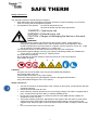
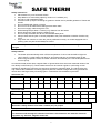
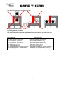
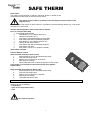
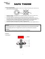
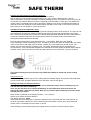
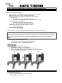
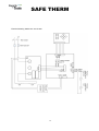
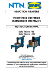
SAFE THERM
Read these operation
instructions attentively
INSTRUCTION MANUAL
Safe therm 700 460V-50A-60Hz
Safe therm 700 400V-60A-50Hz
Safe therm 1200 460V-85A-60Hz
Safe therm 1200 400V-100A-50Hz
NTN-SNR ROULEMENTS
1 rue des Usines – BP 2017
74000 Annecy Cedex - France
www.ntn-snr.com
Control all parts without delay for possible transport
damages. If such damages are determined inform the
carriers immediately
1
SAFE THERM
Table of Contents
1. Safety Instructions
2. Introduction
3. Installation
5. Setting up the Work Piece
6. Positioning the Magnetic Temperature Probe
7. Operation
9. Malfunction / error signals
8. Cleaning and Maintenance
9. Technical Data
10. Electrical drawing
11. Declaration of Conformity
2
SAFE THERM
Safety instructions:
The operation instruction should always be followed
• NTN-SNR shall not be held liable for damages caused by improper handling or by use which
does not comply with the designation purpose.
• Prerequisites of the operator: He must be authorised for use
He must be familiar with the safety precautions
DANGER! = High injury risk
WARNING =Potential injury risk
CAUTION = Danger of damaging the device or the work
piece
WARNING!
Since a magnetic field(4+5)is generated by the induction heater, people wearing a
pacemaker (1)should not work or be in the immediate vicinity of the apparatus. Other
sensitive equipment such as wrist watches, magnetic carriers, electronic circuits, etc. might
also be affected. The safety distance is 1.5 meters (57”)
The equipment should not be used in areas where there is a risk of explosion.
Use protective gloves (danger of burning your hands). Delivered gloved(3) are suitable up to
150°C (302°F). Type Oil Tuff,52-647, made by Ansell.
Hot surface avoid contact(4)
Do not operate an Induction heater in areas where there is a risk of an explosion.
Wear Safety Shoes(8)
1
2
3
4
5
CAUTION
All repair work should be taken care of by an official NTN SNR distributor.
Use original spare parts only.
Protect heater from water or very high humidity.
Protect the yoke support and yokes against corrosion, damage and deformation.
Only preheat ball bearings to max 110°C (230°F).
Safety instructions
•
•
•
•
•
•
The user should have an appreciation of the contents of this manual, and be familiar with safe
workshop practices.
Follow the User Manual at all times.
Ensure that the machine operates at the correct supply voltage. The heater is supplied with a
plug , change should only be made by a suitably qualified person.
Do not use or store the heater in humid environments. NTN-SNR Induction heaters are
designed for indoor use only.
Use proper handling equipment, appropriate for the weight of the work piece or yoke. Never
support arts with a metal cable or have anything metallic hanging in the proximity of the
magnetic field. Extremely high currents can flow through the cable, causing the cable to heat
up.
Do not hold metal objects near the yokes and poles.
3
SAFE THERM
Safety instructions
• Place heater only on a horizontal surface.
• Keep distance to surrounding object by minimum of 1.5 Metre (57”)
• Use only in well ventilated location.
• Prevent to heat up object containing Oil, grease or similar due to possible generator of fumes and
smoke.
• Do not inhale/breath fumes or smoke
• Do not move or lift heater after heating process when warm
• Do not rout supply cable through the core.
• While heating keep at least 1.5 metre (57”)) distance from the heater.
• Never remove the yokes during the heating cycle.
• Do not modify the heater and do not use self-fabricated yokes.
• Always check that the yoke is correctly adjusted to the poles otherwise excessive vibration may
occur.
• Only switch the machine on when the yoke is positioned correctly- on models equipped with a
pivoting yoke, the yoke should always be closed.
Note: Since our products are subject to continuous improvement, we reserve the right to make
changes.
Safety features:
•
•
The heater will automatically switch off if the temperature of coil or heat sink will be higher as
120°C (248°F). Let the heater cool down for 30 minutes and turn on the heater again (E 06).
When using temperature mode, the heater will switch automatically if the rate of temperature rise
is to low (E 03).
An induction heater works due a magnetic field. In figures below there are some measured values of the
flux density in milliTesla (mT). These measurements can be used as a guide in conforming to local
regulations regarding the maximum time exposure of people to magnetic fields. The values below are
only valid for this combination of bearing type and yoke bar. Different configurations may give different
values due to the large variety of bearing types in combination with the different yoke bars.
Safe therm 700
Distance cm
0
10
20
30
40
50
60
70
80
90
X mT
2.4
1.9
0.69
0.4
0.3
0.23
0.16
0.15
0.09
0.08
Y mT
1.77
1.13
0.69
0.4
0.3
0.23
0.16
0.15
0.13
0.09
50
60
70
80
90
100
110
120
130
1.9
0.69
0.4
0.3
0.23
0.16
0.15
0.09
0.08
1.13
0.69
0.4
0.3
0.23
0.16
0.15
0.13
0.09
Safe therm 1200
Distance
0
cm
X mT
4.8
Y mT
3.35
WARNING!
We advise a safety distance of at least 1.5 metre (57”) for people.
CAUTION!
The machine works through an induction field. Bear in mind that this can influence electronic
equipment, e.g. watches, magnetic charts etc.
4
SAFE THERM
Introduction:
The NTN-SNR induction heaters are intended for heating bearings. Other metal components forming a
closed circuit such as bushings, shrink rings, pulleys and gears can also be heated. This will facilitate
mounting where tight fitting is required.
The heaters are designed to heat the work piece up to a maximum temperature of 240ºC (464°F) .
NTN-SNR heaters can be used on continuous bases.
By heating with the time function this has to be checked with an external temperature meter. Place
always the temperature sensor to check within the first heating .
Caution:
Bearings generally should only be heated up to a maximum temperature of 120ºC (248ºF).
Do not use induction heaters for bearings or work pieces, which are outside the minimum or
maximum dimensions as specified in this manual.
Do not switch off the heater with the main switch while heating cycle is running.
Operation condition:
The heater is designed to be used in an industrial environment with an ambient temperature of 0°C to
40°C (32°F to104°F) and an atmospheric humidity of between 5% to 90%. The induction heater is meant
for indoor use only.
Installation:
• Remove packing material and place the induction heater on a non-ferrous, stable, flat
surface. The box will normally contain the heater, a yoke or a set of yokes, the temperature
probe and a pair of heat-resistant gloves.
• Check that the supply voltage and current meet the specifications on the identification plate to
be found on the back of the machine.
• As there are a large number of plug types, every NTN-SNR induction heater is provided with
a plug. When the plug does not fit to your power supply, a suitable plug has to be affixed by a
qualified electrician.
• The wires should be connected as follows:
o Safe therm 700 Brown (Black us): Phase, Blue: Phase (Black us), Green / yellow:
ground.
o Safe therm 1200 Brown (Black us): Phase, Blue: Phase (Black us), Green / yellow:
ground connect the wire (95²) to the fuse box.
• Make sure that the supply cable cannot come into contact with the bearing that is to be
heated. Insert the plug into a shockproof wall socket.
• Connect heater to electric mains,
• Keep distance to surrounding object by 0.5mtr ( 19”)
• Turn main switch from 0 to 1
• . The heater will emit a short beep and in the display 110°C (230 248°F) will appear.
• The induction heater is now ready to be used.
Setting up the work piece
•
•
•
•
•
•
WARNING!
Use appropriate hoisting equipment for heavy components and yokes. The manual lifting
of heavy objects is a common cause of injury.
Wear Safety Shoes while the inductor yokes can slip out of your hands.
The weight of the work-piece should not exceed the maximum weight shown in drawing
below. Exceeding these limits may result in catastrophic equipment failure leading to
personal injury.
Ensure that the mains cable cannot come into contact with the work piece. Damage to the
cable may result in electrocution.
Never support components with a metal cable or have any hanging in the proximity of the
magnetic field. Extremely high currents can flow through the cable causing it to heat up
quickly, resulting in a risk of burning.
5
SAFE THERM
The work piece can be set up only in one way:
Only place part horizontally:
Do not touch the U-core
Lay always part flat on surface
Use always the sliding glassfiber parts between heater and bearing, to protect your part
Safe therm 700
Max dimentions part:
Max inner diameter: 900mm (35”)
Min.inner diameter: 70mm (2.7“)
Max outer diameter: 1000mm (39”)
Min outer diameter 150mm (5.9“)
Max height: 400mm (15.7”)
Min. weight: 30kg (66 lbs)
Max weight part (Bearing): 700KG (1543 lbs)
Max Weight part (solid) : 450KG (992 lbs)
Safe therm 1200
Max dimentions part:
Max inner diameter: 1000mm (39“)
Min.inner diameter: 85mm (3.3“)
Max outer diameter: 1400mm (55“)
Min outer diameter 1500mm (59“)
Max height: 420mm (16.5”)
Min weight: 60kg (132 lbs)
Max weight part (Bearing): 1200KG (2645 lbs)
Max Weight part (solid) : 800KG (1763 lbs)
6
SAFE THERM
Start heater:
The heater can be switched on with the “start/stop” button or remote control.
Standard the heater starts up with the remote control.
The remote control makes it possible to start and stop the heater outside of the
magnetic field.
In case of lost of the remote or other reasons; it is possible to use the start/stop button only. This can be
changed in the user mode:
Activate start/stop button ( direct start without remote!)
Push 10 seconds Start /Stop
¾ In the display appears S08
¾
Push Button C, in the display appears 0,
¾
Change 0 with button A to 1,
¾
Push button C and S08 appears in the display,
¾
Push button B till S05 in the display appears ,
¾
Push Button C, in the display appears 30
¾
Change 30 with button B to 5,
¾
Push button B till S05 in the display appears ,
¾
Push button A till S09
¾
Push button C and 110°C appears in display
Start button activated
Activate Remote control
Start the heater with the remote control:
1.
Set temperature, time or temperature/time ramp,
2.
Push the start /stop button,
3.
Display will count down for 30 seconds,
4.
Step away from heater,
5.
Start heater within this 30 seconds with the remote control.
If the heater is not activated in these 30 seconds: E13 appears
Repeat above.
Start the heater with start/stop button only:
1.
Set temperature, time or temperature/time ramp,
2.
Push the start /stop button,
3.
Display will count down for 5 seconds,
4.
Step away from heater,
5.
The heater will start to heat.
AT ALL TIMES PROCESS CAN BE INTERRUPTED BY PRESSING "STOP"
Heating can be conducted by:
- Temperature
- Time versus temperature ramp
- Time
Use protective gloves!
7
SAFE THERM
Control of the temperature
• Place magnetic probe on work piece, close to the bore. Make sure that the place reserved for the
probe is free of any grease or oil.
•
•
•
•
•
•
Always use magnetic temperature probe (hereafter referred to as the 'probe') for heating in the
Temperature Mode.
The probe is suitable for operation up to a maximum temperature of 240ºC (484°F)
As a safety feature, the connection between magnet and probe will break above the maximum
temperature. If this occurs when operating in the Temperature Mode, the machine will turn itself off
since the probe will fail to register any increase in the temperature over a set period of time.
A probe fixed to a clamp is also available when heating non-magnetic work pieces.
Ensure that the area where the probe is located is completely clean.
Connect the probe by inserting the plug into the socket at the side of the heater, watch out for + -!
CAUTION:
Treat the probe with care. It is a valuable part of the heater and can easily be broken through
careless handling. After use, we suggest that it is placed on the side of the vertical pole.
WARNING!
If in any doubt, isolate the machine and contact your local distributor.
Operation:
Control panel:
8
SAFE THERM
Heating with temperature pre-selection function:
When heater is switched on the display will show: 110°C (230°F)
With A and B you can decrease the temperature to 0°C (32°F) and increase to 240°C. (484°F)
Select temperature and press "start/stop” to start the heating process. The heater will first count down for
30 seconds, this makes it able for the user to step away from the heater 1 meter( 38”), start heater with
remote control. The display will now show progress of heating cycle. Once pre-selected temperature is
reached the acoustic signal will sound and the display will flash. Press “stop on the remote control and
place probe on one of the poles, remove work piece.
Heating time Versus temperature ramp.
This is specially developed for the heating of gears and bearings with a small clearance. The user can set
the temperature and time; the heater will heat the part exactly to the preset temperature in the preset
time. The major advantage this provides is the temperature differential between the internal and external
component material remains low thus reducing the potential for material stress accumulation and
subsequent potential distortional damage.
Press D and set temperature, press E and set time ( > 10 minutes). Both LED’s are lightning.
Press "start/stop” to start the heating process. The heater will first count down for 30 seconds, this makes
it able for the user to step away from the heater 1 meter( 38”), start heater with remote control. The
display will now show progress of heating cycle. The power will automatically be regulated by the
microprocessor. Once pre-selected temperature is reached the acoustic signal will sound and the display
will flash. Press “stop on the remote control and place probe on one of the poles, remove work piece.
This slower heating process will avoid a big differential between A and B: low stress heating
method
Temperature hold:
As soon as the temperature drops 5°C/F, heating will automatically repeat. This process will repeat itself
5 times. Press "stop" and place probe on one of the poles, remove work piece.
Heating with time pre-selection function:
Heating on the time pre-selection is only to use in production areas where constantly only one
and the same part will be heated up!
Heat the part that have to be heated repeatability on the temperature mode and control the
heating time with a separate stop watch. Now you can heat the part constantly on the time mode
without placing a sensor.
When heater is switched on the display will show : 110°C (230°F)
Switch on the heater and press button E
The display will show : 00.00
Select time and press "start/stop” to start the heating process. The heater will first count down for 30
seconds, this makes it able for the user to step away from the heater 1 meter( 38”), start heater with
remote control. The display will count down to 00.00.
When heating cycle has ended the acoustic signal will sound .Press C and remove work piece.
9
SAFE THERM
DO NOT USE THE TIME MODE ON ANY OTHER WAY AS DESCRIPTED ABOVE!
HEATING PROCESS MAY NOT BE STARTED UNLESS THE YOKE IS CORRECT IN PLACE OVER THE POLES.
Malfunctioning / Error Signals:
E 01: The probe is not plugged in or the cable of the probe is broken
E 02: The probe is not correct connected, please check.
E 03: The increase of temperature is lower than 1°C in 1 minute.
Please check:
• The probe, no damage and placed properly.
• The part can be too big for the machine (heating time to long).
E 04: No change in Temperature
• The probe, no damage and placed properly.
• The connection from probe to the circuit board
E 06: Coil or heat sink is too hot ( more than 120°C)
•
Inform your distributor.
E08: No zero crossing Triac.
•
Inform your distributor.
Press “start/stop” and check which of above possibilities is causing the Error signal.
WARNING!
Proper maintenance and handling practices are critical. Failure to follow installation instructions
and to maintain proper lubrication can result in equipment failure, creating a risk of serious
injuries
If a loud vibrating noise is heard, first check:
• Are the contact surfaces clean and greased sufficiently
• Are the yokes 100% in contact with the surface?
Adjustment yokes:
1. Check if the grinded side is smooth.
2. Place yoke or pivoting yoke on the heater.
3. Unscrew the screws in yoke and pivoting point an 1/4 turn.
4. Turn on the heater and the yoke will set itself or use a nylon hammer.
5. Fasten screws and turn off heater.
3
4
5
WARNING! If in any doubt, isolate the machine and contact your local distributor.
Cleaning and maintenance:
y
Store in a dry, frost-proof area, free from humidity.
y
Keep clean with a soft, dry cloth.
10
SAFE THERM
y
y
Keep the contact parts of the poles clean. Grease regularly with an acid free grease for optimal
contact with the yokes and to avoid corrosion (on swing-arm models, also grease the vertical pin
regularly).
Contact your supplier if there is any suspicion of malfunctioning.
Technical data
TYPE
Voltage
Power
Temperature control
Heating speed control
Overall dimensions
Mass. heater
Spare parts list
TYPE:
Induction yoke
Tool ST700-yoke 45
Tool ST700-yoke 60
Tool ST700-yoke 70
Tool ST700-yoke 85
Tool ST700-yoke 100
Tool ST700-yoke 115
Tool ST700-yoke 130
Tool ST700-yoke 145
Magnetic probe
Tool Temp Probe 1000
Crane
Tool ST700-Lifting device
TYPE
Voltage
Power
Temperature control
Heating speed control
Overall dimensions
Mass. heater
Spare parts list
TYPE:
Induction yoke
Tool ST1200-yoke 85
Tool ST1200-yoke 115
Tool ST1200-yoke 145
Tool ST1200-yoke 215
Magnetic probe
Tool Temp Probe 1500
Crane
Tool ST1200-Lifting device
Safe therm 700
460V-50A-60Hz / 400V-60A-50Hz
23KVA
Max. 110°C (230°F)
Microprocessor controlled
1000x1400x1400mm (39”x55”x55”)
Max. weight work piece Solid components: 450 kg (922
lbs) Bearings: 700 kg (1543 lbs)
350 kg (771lbs)
ART. No.
Safe therm 1200
460V-88A-60Hz / 400V-100A-50hz
46KVA
Max. 110°C (230°F)
Microprocessor controlled
1400x2000x1600mm (55”x78”x62”)
Max. weight work piece: Solid components: 800 kg (1763
lbs) Bearings: 1200 kg (2645 lbs)
850 kg (1870lbs)
ART. No.
11
SAFE THERM
Electrical drawing Safe therm 700 & 1200
12
SAFE THERM
Herewith we declare that the supplied version of:
Name product:
Type product:
Induction heater
Safe therm 700 + Safe therm 1200
Complies with the following provisions applying to it:
Electrical safety
: IEC 335-1 classification 1
: IEC 664-1 Category 2
EMC emission
: EN 55011 (1998) + A1 (1999) + A2 (2002)
: EN 61000-3-2
: EN 61000-3-3
EMC immuniteit
: EN 61000-6-2
Other information:
This product complies with technical standards specifications as defined by
low voltage directive 73/23/EEG and EMC directive 89/336/EEC
Induction Heating Systems : Warranty Terms and Conditions
NTN-SNR guarantees this product to be free from defects in material and
workmanship for a period of 3 years from date of purchase. It remains the
customer’s responsibility to provide proof of this date of purchase. During the
warranty period NTN-SNR will either repair or replace any product that proves to
be defective.
This warranty does not apply to defects resulting from product modification or misuse of
any product or part without NTN-SNR’s written consent. Furthermore, this warranty
does not apply to fuses or problems arising from normal wear or failure to follow
instruction.
Neither NTN-SNR nor it’s employees shall be liable for any direct or indirect damages
arising either out of any defects in the products or the use of the products, even if NTNSNR has been informed in advance of the possibility of such damage. Such excluded
damages shall include, but are not limited to: costs of removal and installation, losses
substained as the result of injury to any person, or damage to property.
13
DOC.I_SAFETHERM.CU.GBb
Limitations :